EP1911574A1 - A paper material with an improved embossed pattern and method for the production thereof - Google Patents
A paper material with an improved embossed pattern and method for the production thereof Download PDFInfo
- Publication number
- EP1911574A1 EP1911574A1 EP07425604A EP07425604A EP1911574A1 EP 1911574 A1 EP1911574 A1 EP 1911574A1 EP 07425604 A EP07425604 A EP 07425604A EP 07425604 A EP07425604 A EP 07425604A EP 1911574 A1 EP1911574 A1 EP 1911574A1
- Authority
- EP
- European Patent Office
- Prior art keywords
- ply
- embossed
- protuberances
- sheet material
- embossing
- Prior art date
- Legal status (The legal status is an assumption and is not a legal conclusion. Google has not performed a legal analysis and makes no representation as to the accuracy of the status listed.)
- Granted
Links
- 239000000463 material Substances 0.000 title claims abstract description 101
- 238000000034 method Methods 0.000 title claims description 19
- 238000004519 manufacturing process Methods 0.000 title claims description 7
- 238000004049 embossing Methods 0.000 claims abstract description 132
- 238000004140 cleaning Methods 0.000 claims abstract description 12
- 239000003292 glue Substances 0.000 claims description 27
- 238000004026 adhesive bonding Methods 0.000 claims description 5
- 238000003475 lamination Methods 0.000 description 17
- 238000010030 laminating Methods 0.000 description 15
- 230000006835 compression Effects 0.000 description 5
- 238000007906 compression Methods 0.000 description 5
- 239000012634 fragment Substances 0.000 description 5
- 230000000694 effects Effects 0.000 description 4
- 238000010521 absorption reaction Methods 0.000 description 3
- 238000010586 diagram Methods 0.000 description 3
- 229920002678 cellulose Polymers 0.000 description 2
- 239000001913 cellulose Substances 0.000 description 2
- 230000009977 dual effect Effects 0.000 description 2
- 230000008092 positive effect Effects 0.000 description 2
- 239000000126 substance Substances 0.000 description 2
- 229910000831 Steel Inorganic materials 0.000 description 1
- 239000000853 adhesive Substances 0.000 description 1
- 230000001070 adhesive effect Effects 0.000 description 1
- 230000015572 biosynthetic process Effects 0.000 description 1
- 230000001419 dependent effect Effects 0.000 description 1
- 238000009826 distribution Methods 0.000 description 1
- 239000007788 liquid Substances 0.000 description 1
- 238000003754 machining Methods 0.000 description 1
- 230000013011 mating Effects 0.000 description 1
- 238000003672 processing method Methods 0.000 description 1
- 239000010959 steel Substances 0.000 description 1
- 238000009827 uniform distribution Methods 0.000 description 1
Images


Classifications
-
- B—PERFORMING OPERATIONS; TRANSPORTING
- B31—MAKING ARTICLES OF PAPER, CARDBOARD OR MATERIAL WORKED IN A MANNER ANALOGOUS TO PAPER; WORKING PAPER, CARDBOARD OR MATERIAL WORKED IN A MANNER ANALOGOUS TO PAPER
- B31F—MECHANICAL WORKING OR DEFORMATION OF PAPER, CARDBOARD OR MATERIAL WORKED IN A MANNER ANALOGOUS TO PAPER
- B31F1/00—Mechanical deformation without removing material, e.g. in combination with laminating
- B31F1/07—Embossing, i.e. producing impressions formed by locally deep-drawing, e.g. using rolls provided with complementary profiles
-
- D—TEXTILES; PAPER
- D21—PAPER-MAKING; PRODUCTION OF CELLULOSE
- D21H—PULP COMPOSITIONS; PREPARATION THEREOF NOT COVERED BY SUBCLASSES D21C OR D21D; IMPREGNATING OR COATING OF PAPER; TREATMENT OF FINISHED PAPER NOT COVERED BY CLASS B31 OR SUBCLASS D21G; PAPER NOT OTHERWISE PROVIDED FOR
- D21H27/00—Special paper not otherwise provided for, e.g. made by multi-step processes
- D21H27/30—Multi-ply
-
- B—PERFORMING OPERATIONS; TRANSPORTING
- B31—MAKING ARTICLES OF PAPER, CARDBOARD OR MATERIAL WORKED IN A MANNER ANALOGOUS TO PAPER; WORKING PAPER, CARDBOARD OR MATERIAL WORKED IN A MANNER ANALOGOUS TO PAPER
- B31F—MECHANICAL WORKING OR DEFORMATION OF PAPER, CARDBOARD OR MATERIAL WORKED IN A MANNER ANALOGOUS TO PAPER
- B31F2201/00—Mechanical deformation of paper or cardboard without removing material
- B31F2201/07—Embossing
- B31F2201/0707—Embossing by tools working continuously
- B31F2201/0715—The tools being rollers
- B31F2201/0723—Characteristics of the rollers
- B31F2201/0733—Pattern
-
- B—PERFORMING OPERATIONS; TRANSPORTING
- B31—MAKING ARTICLES OF PAPER, CARDBOARD OR MATERIAL WORKED IN A MANNER ANALOGOUS TO PAPER; WORKING PAPER, CARDBOARD OR MATERIAL WORKED IN A MANNER ANALOGOUS TO PAPER
- B31F—MECHANICAL WORKING OR DEFORMATION OF PAPER, CARDBOARD OR MATERIAL WORKED IN A MANNER ANALOGOUS TO PAPER
- B31F2201/00—Mechanical deformation of paper or cardboard without removing material
- B31F2201/07—Embossing
- B31F2201/0707—Embossing by tools working continuously
- B31F2201/0715—The tools being rollers
- B31F2201/0723—Characteristics of the rollers
- B31F2201/0738—Cross sectional profile of the embossments
-
- B—PERFORMING OPERATIONS; TRANSPORTING
- B31—MAKING ARTICLES OF PAPER, CARDBOARD OR MATERIAL WORKED IN A MANNER ANALOGOUS TO PAPER; WORKING PAPER, CARDBOARD OR MATERIAL WORKED IN A MANNER ANALOGOUS TO PAPER
- B31F—MECHANICAL WORKING OR DEFORMATION OF PAPER, CARDBOARD OR MATERIAL WORKED IN A MANNER ANALOGOUS TO PAPER
- B31F2201/00—Mechanical deformation of paper or cardboard without removing material
- B31F2201/07—Embossing
- B31F2201/0758—Characteristics of the embossed product
- B31F2201/0761—Multi-layered
- B31F2201/0764—Multi-layered the layers being nested
-
- B—PERFORMING OPERATIONS; TRANSPORTING
- B31—MAKING ARTICLES OF PAPER, CARDBOARD OR MATERIAL WORKED IN A MANNER ANALOGOUS TO PAPER; WORKING PAPER, CARDBOARD OR MATERIAL WORKED IN A MANNER ANALOGOUS TO PAPER
- B31F—MECHANICAL WORKING OR DEFORMATION OF PAPER, CARDBOARD OR MATERIAL WORKED IN A MANNER ANALOGOUS TO PAPER
- B31F2201/00—Mechanical deformation of paper or cardboard without removing material
- B31F2201/07—Embossing
- B31F2201/0758—Characteristics of the embossed product
- B31F2201/0761—Multi-layered
- B31F2201/0766—Multi-layered the layers being superposed tip to tip
-
- D—TEXTILES; PAPER
- D21—PAPER-MAKING; PRODUCTION OF CELLULOSE
- D21H—PULP COMPOSITIONS; PREPARATION THEREOF NOT COVERED BY SUBCLASSES D21C OR D21D; IMPREGNATING OR COATING OF PAPER; TREATMENT OF FINISHED PAPER NOT COVERED BY CLASS B31 OR SUBCLASS D21G; PAPER NOT OTHERWISE PROVIDED FOR
- D21H27/00—Special paper not otherwise provided for, e.g. made by multi-step processes
- D21H27/002—Tissue paper; Absorbent paper
Definitions
- the invention relates to improvements to embossed web materials, especially based on tissue paper, of the multi-ply type, i.e. comprising at least two plies bonded together, typically and preferably by gluing.
- the invention also relates to improvements to the processing methods to emboss materials made of tissue paper or the like, to obtain new and improved functional characteristics.
- the invention also relates to a method for the production of a material of this type.
- Embossing is one of the operations that are normally performed on plies or sheets of tissue paper, to produce paper articles for personal and household cleaning and hygiene, and also for professional and industrial use, such as toilet paper, kitchen towels, paper napkins and handkerchiefs and the like.
- Embossing is an operation that is performed for the dual purpose of improving aesthetic properties and increasing functional properties, in particular the softness, smoothness, absorption capacity or thickness of the finished material.
- tissue paper material such as kitchen towel or toilet paper
- a tissue paper material is produced from two or more plies of paper embossed separately and subsequently bonded together by applying a glue and laminating the plies between counter-rotating rollers defining a lamination nip.
- Embossing is, for example, performed by feeding each ply between an embossing roller, provided with protuberances, and a pressure roller with an outer surface coated in yielding material, such as rubber or the like.
- embossing is performed between two rollers made of steel or another hard material, one equipped with protuberances and the other with corresponding recesses.
- the protuberances of the embossing roller produce corresponding protuberances or projections in the paper ply.
- the protuberances formed in the two outermost plies are facing the inside of the finished product.
- the two plies of paper web material are bonded by making at least some of the protuberances of one ply coincide with the protuberances of the other ply, having previously applied glue to the protuberances of one of the two plies, or to at least some of these protuberances.
- two embossing rollers which emboss the two paper plies separately by means of respective pressure rollers, form therebetween a lamination nip, through which the two embossed plies are fed before being detached from the rollers.
- the protuberances of one roller coincide with the protuberances of the other roller and the reciprocal distance between the rollers is such as to cause localized compression of the plies at said protuberances.
- a tip-to-tip embossing unit to obtain a product of this type is described in US-A-3,414,459 . Further tip-to-tip embossing units are described in US-A-5,173,351 ; US-A-6,032,712 ; US-A-6,245,414 ; US-A-6,053,232 and US-A-3, 961,119 .
- the two plies are embossed separately, each between an embossing roller and a counter-roller or pressure roller, and then matched so that the protuberances of one ply are inserted between the protuberances of the other ply.
- Lamination of the two plies to obtain reciprocal bonding is performed between one of the embossing rollers an a laminating roller, while the two embossing rollers do not normally touch. Examples of embossing-laminating devices of this type are described in US-A-3,556,907 ; US-A-3,867,225 ; US-A-5,339,730 .
- US-A-5,686,168 describes a method of nested embossing, wherein the plies are bonded by lamination between two opposed embossing rollers.
- US-A-6,578,617 and US-A-6,470,945 describe embossing units that can perform embossing according to both techniques, i.e. nested or tip-to-tip.
- the reciprocal angular position and/or the reciprocal axial position of the two embossing rollers can be modified.
- US-A-6,261,666 describes an analogous device for alternatively performing tip-to-tip or nested embossing. Another similar device is described in US-A-6,109,326 .
- embossing was performed according to very simple geometric patterns, with uniform distribution of truncated-cone or truncated-pyramid shaped protuberances. These embossings had a prevalently technical function, and were used to produce a product of adequate thickness and with sufficient softness and absorption capacity.
- embossing must increasingly achieve a dual function, both technical-functional and aesthetic. Therefore, embossing patterns and embossing devices have been developed which make it possible to obtain a product that is aesthetically pleasing and at the same time suitable to satisfy the aesthetic requirements and increasing commercial requirements demanded of these products. Examples of complex embossing patterns with a technical and aesthetic function are described in US-A-6,136,413 ; US-A-5,846,636 ; US-A-6,106,928 .
- embossing tissue paper products has always been aimed at increasing the liquid absorption properties and apparent thickness of the product.
- embossing was, and continues to be, utilized prevalently in the field of kitchen towels, more than in the field of toilet paper.
- An object of the invention is to produce an embossing pattern that gives the tissue paper a different function from that of conventional products.
- the invention relates to a method to increase the cleaning capacity of a sheet of multi-ply tissue paper comprising a first surface and a second surface, wherein at least one of said first and second surfaces is embossed to obtain surface portions defining outwardly projecting protuberances projecting of the sheet, delimited at least partly by substantially linear grooves extending inside the sheet, said grooves defining spaces to collect a material removed by passing said sheet over a surface to be cleaned, and said outwardly projecting protuberances defining areas of surface contact with said surface to be cleaned.
- a glue is applied to some or all of the lines defining the bottom of the substantially linear grooves.
- the areas of embossed ply forming the outwardly projecting protuberances are more resistant to compression, as the portion of outwardly projecting ply material of the web material is at least partly surrounded by lines of glue, which bond the material of the ply to the ply below, preventing the intermediate ply material from collapsing.
- This increased resistance to compression is useful both to preserve the form of the product wound in a roll, and to maintain the three-dimensional nature of the embossing pattern during use, e.g. when the product is passed over the surface to be cleaned exerting a certain amount of pressure.
- the invention relates to a tissue paper sheet material with a first surface and a second surface, comprising at least two plies of tissue paper bonded together by gluing, wherein a three-dimensional cleaning surface pattern is produced on at least said first surface of said sheet material, to clean surfaces over which said sheet material is passed with said three-dimensional surface pattern in contact with the surface to be cleaned, and wherein said three-dimensional surface pattern comprises surface portions defining outwardly projecting protuberances of said sheet material, at least partly delimited by grooves with substantially linear extension, extending towards the inside of said sheet material, said grooves defining spaces to collect the material removed by passing said sheet over said surface to be cleaned and said outwardly projecting protuberances defining areas of surface contact with said surface to be cleaned.
- the invention provides a tissue paper multi-ply sheet material and a method for the manufacturing thereof, said sheet material including at least a first outer ply and a second outer ply of tissue paper bonded by gluing, said first outer ply having a first, outwardly facing surface and a second, inwardly facing surface; wherein at least said first outer ply has a three-dimensional surface pattern comprising outwardly projecting, bulging embossed protuberances defined by portions of said first outer ply, at least partly surrounded by substantially linear grooves, extending towards the inside of said sheet material, and wherein said first outer ply is provided with glue applied on the second, inwardly facing surface of said first outer ply in correspondence of said linear grooves.
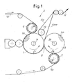
- Figure 1 shows a diagram of an embossing unit, also known as embossing-laminating unit, indicated as a whole with 2.
- the unit comprises a first embossing roller 1 and a second embossing roller 3, rotating about respective rotation axes 1A and 3A. The directions of rotation are indicated with f1 and f3.
- a nip G is defined between the two embossing rollers, through which two plies of tissue paper V1 and V3 are fed, which are separately embossed by the rollers 1 and 3, respectively.
- Embossing takes place by feeding each of the plies between the respective embossing roller 1 or 3 and a corresponding pressure roller 5 or 7, the axes of rotation of which are indicated with 5A and 7A.
- rollers 5 and 7 are coated with a layer of yielding material, such as rubber or the like, in which protuberances, indicated schematically and as a whole with 1 P and 3P in Figure 1, with which the embossing rollers 1 and 3 are equipped penetrate. Possible configurations of these protuberances will be described in detail hereunder.
- the two rollers 1 and 3 can be phased to position the protuberances 1 P and 3P in the tip-to-tip or nested configuration.
- the first condition in the lamination nip G at least some of the protuberances of the roller 1 coincide with the protuberances of the roller 3 and the distance between the rollers 1 and 3 is such that sufficient pressure is exerted between the protuberances to cause lamination and bonding of the plies V1 and V3.
- the protuberances 1 P are intercalated between the protuberances 3P.
- the unit When, on the other hand, the unit is two-purpose and can operate both in tip-to-tip and nested mode, the rollers are reciprocally positionable with angular and/or axial phasing.
- the mechanical members and in particular the supports for the rollers 1 and 3 which allow adjustment are known per se and will not be described in greater detail herein.
- a glue dispensing unit is indicated schematically with 17, and applies a glue to the radially projecting surfaces of the ply V1 embossed by the roller 1, when this ply is still engaged with the surface of said roller 1.
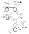
- FIG. 2 schematically shows the conformation of a different possible embossing machine or unit, of the type described, for example, in WO-A-99/44414 .
- the two plies of tissue paper again indicated with V1 and V3, are fed towards an embossing unit or embossing-laminating unit 100 comprising an embossing roller 101 equipped with protuberances 101 P and cooperating with a lamination or marrying roller 103, which can optionally be coated with a material which is softer, or more yielding than the material forming the surface of the embossing roller 105.
- a glue dispenser 107 cooperates with the embossing roller 105 to apply glue to the protuberances produced through embossing by the projections 101 P in the ply V1 through pressure between the embossing roller 101 and a pressure roller 109 coated in rubber or another yielding material.
- the ply V1 before being guided about the pressure roller 109, the ply V1 is fed into a secondary embossing unit 111 with an embossing roller 113 cooperating with a pressure roller 115.
- the surface of the embossing roller 113 is equipped with micro-embossing protuberances 113P.
- the ply V3 is fed through a second secondary embossing unit 114, comprising an embossing roller 117, the surface of which is equipped with projections or protuberances 117P, cooperating with a pressure roller 119 similar to the pressure roller 115.
- the secondary embossing unit 111 can be omitted, as can the secondary embossing unit 114, depending on the type of pattern and machining to be performed on the paper material formed by the two plies V1, V3.
- the glue applied by the dispensing unit 107 to the projections of the paper deformed between the pressure roller 109 and the embossing roller 101 is used to reciprocally bond the two plies, which for this purpose are laminated in the nip formed by the embossing roller 101 and the mating roller 103 to form multi-ply web material N delivered from the embossing unit 100.
- Figures 3 to 8 schematically show, in various views and sections, portions of a multi-ply web material produced with one or other of the embossing units in Figures 1 and 2, or other equivalent embossing units, utilizing the concepts underlying the invention.
- Figure 3 represents a local section and partial perspective view of a portion of a multi-ply web material constituted by two plies V1 and V3 embossed and laminated in tip-to-tip configuration with a glue C to bond the two plies at the level of grooves produced on said plies by the protuberances 1 P and 3P of the embossing rollers 1, 3 of the device in Figure 1 or other equivalent device.
- the grooves, indicated with 201 for the ply V1 and with 203 for the ply V3, have a substantially linear extension and defined therebetween are bulging portions 205, 207 of the web material formed by the outwardly projecting plies V1, V3 of the web material defining projections with an elongated extension delimited by adjacent grooves 201, 203.
- Figure 6 schematically shows in a top view a portion of the web material N, i.e. observed from the side of the ply V1, embossed as described above.
- the projections 205 and the grooves 201 have a slightly undulating linear shape and the width of the portions 205 is much greater than the width of the grooves 201.
- a very efficient cleaning effect is obtained on the surface, due to the fact that the portions 205 of material project outward to form contact and cleaning surfaces, while the grooves 201 define areas to collect the substances or products located on the surface to be cleaned and which must be removed.
- the rounded convex conformation of the outwardly projecting portions 205 of the ply V1 and of the outwardly projecting portions 203 of the ply V3 make the product soft and pleasing to the touch.
- the cleaning effect is provided to the same degree on both faces of the web material.
- the portions 205, 207 project from the base plane of the original ply, i.e. from the surface on which the first ply lies before deformation by embossing.
- the grooves 201, 203 project towards the inside of the web article and the protuberances 205, 207 project outward to form bulges or embossings with positive effect.
- Embossing with positive effect is intended as an effect of deformation through embossing wherein the cellulose ply has been deformed to project from the surface of the original ply in relation to the shape thereof prior to embossing.
- each ply V1, V3 is in actual fact composed of a plurality of cellulose layers, to provide adequate consistency and mechanical resistance to the finished product.
- resistance to compression can be obtained by producing the web material N with an embossing technique of the nested type, as indicated schematically in Figure 4.
- the web material N is again formed by the plies V1 and V3, where the ply V1 is embossed to obtain grooves, again indicated with 201, having a linear extension, defined between which are areas 205 with outwardly projecting convex profiles, i.e. areas of positive embossing.
- the ply V3 is embossed to form thereon projections 209 facing the inside of the web material N and inserted in the empty space defined by the portions 205 of the ply V1.
- the protuberances 209 therefore form supports for the convex areas 205 of the ply V1 preventing or in any case reducing compression thereof.
- the protuberances 209 facing the inside of the web material are approximately in the shape of truncated cones, but it must be understood that they can also have a conformation with linear extension like the grooves 201 produced on the ply V1.
- the two plies V1 and V3 are bonded by a glue 5 applied to the surface of the ply V1 facing the ply V3 at the level of the grooves 201.
- the conformation of the surface of the ply V1 can substantially be identical to the one illustrated in Figure 6, with grooves 201 with an undulated linear extension and corresponding convex projections 205 with a width preferably greater than the width of the grooves 201.
- the article N configured as shown in Figure 4 will have a preferred active surface defined by the ply V1, with a cleaning capacity, i.e. capacity to remove dirt from the surfaces to be cleaned, substantially equivalent to that of the web material N in Figure 3.
- the lower surface of the material, defined by the ply V3 has a lesser cleaning capacity, substantially equivalent to as that of conventional products.
- Figure 5 shows a local section and partial perspective view of a web material N obtained, for example, with an embossing-laminating device of the type illustrated in Figures 2, 2A and 2B.
- the ply V1 is still embossed as described with reference to Figures 3 and 4, with the formation of convex projections 205 with a substantially linear extension delimited by grooves 201.
- the glue C with which the ply V1 is bonded to the ply V3 below is applied at the level of the grooves 201.
- the ply V3 has micro-embossing obtained with the embossing unit 114.
- the ply V1 has no micro-embossing, and therefore the secondary embossing unit 111 substantially remained idle or is not present. It would also be possible for the ply V1 to have micro-embossing over which the embossing forming the projections 205 and the grooves 201 is positioned.
- the surface conformation of the ply V1 can be the same as that shown in Figure 6.
- Figure 7 shows a top view of a different embossing pattern of the ply V1 and/or of the ply V3.
- the same numbers indicate the same or equivalent parts to those shown in Figure 6.
- the pattern is characterized by a more marked undulation of the protuberances and of the grooves on the surface of the ply.
- Figure 8 shows a local section of an embossed web material according to the invention obtained, for example, with an embossing-laminating unit as shown in Figure 1.
- the same numbers indicate the same or equivalent parts to those in Figure 4.
- inside the empty space produced under the projections 205 are several adjacent protuberances or projections 209 produced on the ply V3.
- Figure 9 shows a top view of a fragment of an embossed web material according to the invention, with a different surface structure.
- grooves again indicated with 201, are produced on the surface of the ply V1, arranged to at least partly surround raised areas, i.e. outwardly facing convex areas, indicated with 205.
- These areas 205 form projections embossed according to a positive embossing as defined above.
- Figure 9 shows a fragment of the web material with one of these projecting portions 205, surrounded by grooves 201 divided into four contiguous portions. It must be understood that on the surface of the web material there can be a plurality of grooves 201 defining the same number of projections 205 arranged according to a suitable pattern.
- the grooves can have a different conformation, e.g. they can fully surround the projecting portions 205, and/or they can have a different geometrical shape in relation to the one shown.
- Figure 10 shows a local section of a portion of the web material shown in Figure 9, in which it can be seen that arranged under the convex projection 205 are protuberances, still indicated with 209, produced in the ply V3 and arranged in nested configuration in the empty space inside the web material below the convex projections 205.
- the lower ply V3 can be embossed with micro-embossing as shown in Figure 5, or with a similar pattern to that of the ply V1 in a tip-to-tip embossed configuration as shown in Figure 3 or in any other suitable way.
- the projections 205 are constituted by areas almost closed and surrounded by grooves 201, which no longer extend for a substantially indefinite length like those in Figures 6 and 7.
- the convex projecting portions 205 again define contact and cleaning surfaces, while the grooves 201 define spaces to collect the dirt and debris removed from the surface cleaned with the web material N.
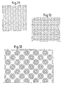
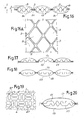
- Figures 11 and 13 schematically show further possible embossing patterns according to the invention.
- the lines represented in the drawings indicate embossing motifs or patterns with linear extension, according to closed lines.
- Figure 11 shows embossing patterns characterized by embossed lines with double lobes, delimiting an inner surface forming an outwardly facing convex projection of the web material.
- Figure 12 shows an embossing pattern characterized by groups of closed, V-shaped embossing lines with a wide aperture, arranged to produce a sort of flower.
- Figure 13 shows closed embossing lines similar to the lines in Figure 12, but arranged according to parallel and intercalated alignments.
- the ply embossed with the embossing lines defining the outwardly projecting areas of the web material can also have conventional embossing, intercalated with these embossing lines forming the grooves, to "embed" the areas embossed with positive embossing in areas embossed according to a conventional embossing motif.
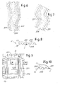
- FIG 14 shows a diagrammatic side view of an embodiment of an embossing unit for manufacturing a multi-ply embossed paper sheet according to the invention in a particularly preferred embodiment.
- the unit designated 301 as a whole, includes a first embossing roller 303 and a second embossing roller 305, defining a lamination nip 307 therebetween. An enlargement of the lamination nip 307 is shown in Fig.15.
- Each embossing roller 303, 305 co-acts with a corresponding pressure roller 309, 311.
- the pressure rollers 309, 311 are provided with an outer pliable cover, made of elastically yielding material, such as rubber or the like, shown at 309A and 311A respectively.
- Each embossing roller forms, along with the corresponding pressure roller, an embossing nip, through which a respective first and second outer ply V1 and V3 are fed.
- a glue applicator 313 applies glue on the top surface of the embossing protrusions generated on ply V1 by the coaction of rollers 303 and 309.
- a similar glue applicator can be arranged around the embossed roller 305.
- a first and a second intermediate plies V5, V7 are fed into the lamination nip 307 between embossing rollers 303, 305.
- Each ply V5, V7 is embossed in a respective auxiliary embossing device 315, 317.
- Each auxiliary embossing device includes an embossing roller 315A, 317A provided with outwardly oriented protrusions (see enlargement of roller 315A), co-acting with a pressure roller 317A, 317B provided with an elastic yielding surface.
- the two embossing rollers 303, 305 are provided with protrusions 303P and 305P.
- the protrusions 303P, 305P are arranged in a tip-to-tip or foot-to-foot arrangement as shown in detail in Fig.15. This means that the protrusions of one roller are substantially in phase with those of the opposing roller.
- the four plies V1, V3, V5, V7 are laminated together at the mutually corresponding top surfaces of the opposing protrusions 303P, 305P, so that they are glued together by means of the adhesive applied by the glue distributor 313 and possibly by the second glue distributor 313A (if present).
- Fig 16 shows an enlarged diagrammatic cross section of a product which can be obtained with the unit of Figs. 14, 15.
- the outer plies V1, V3 are embossed such as to form bubbles or bulging protrusions B and B1 extending towards the outside.
- Inwardly oriented depressions or grooves D and D1 are generated in the two plies by the protrusions 303P, 305P of the rollers 303 and 305.
- the two inner plies V5, V7 are arranged within the outer plies V1, V3 and their protrusions (generated by auxiliary embossing devices 315, 317 protrude towards the outer plies V1, V3, such as to form a supporting structure, which limits the risk of the bulging protrusions B, B1 collapsing towards the interior of the product.
- the height H of the bulging protrusions extending towards the outside of the product can be larger than the height h of the inner protrusions formed in the intermediate plies.
- the height H can range from 1.2 to 1.6 mm and preferably around 1.4 mm, while the height h can range between 1.0 and 1.4 and preferably between 1.1 and 1.3 mm. It shall be understood that these values are given by way of example only and are not to be considered limitative of the invention.
- Fig.16A shows a top plan view of a fragment of a product according to the invention.
- Bulging protrusions are shown again at B, each protrusion being surrounded by a closed inwardly oriented linear groove or depression D.
- the bottom portions of the grooves or depressions D (or at least part thereof) are provided with glue.
- each protrusion B is entirely surrounded by a groove or depression D extending along a closed line.
- This line can be however only substantially closed, i.e. it can partly but not entirely surround the protrusion B.
- a substantially closed line shall be understood as a line, which covers at least 60% and preferably at least 70% and most preferably at least 80% of the linear perimeter of the protrusion B.
- the bulging protrusions B extend towards the outside forming a sort of bubble.
- the bubble is at least partly prevented from collapsing by the linear glue distribution along the partly or entirely closed groove or depression line D surrounding the protrusions B, in combination with the protrusions of the intermediate plies V5, V7.
- Fig.17 shows a modified embodiment of the product according to the invention.
- the second outer ply V3 is substantially smooth, i.e. not embossed.
- This product can be achieved by removing or making the auxiliary embossing device 313 inactive and by replacing the roller 305 with one which is substantially smooth, i.e. not provided with protrusions.
- the roller 305 can be moved away from roller 303, such that the two rollers are not pressed one against the outer in the lamination nip 307 and a further marrying or lamination roller with a smooth surface is arranged e.g. downstream of the nip 307, said marrying or lamination roller being pressed against the protrusions of roller 303.
- Figs. 19, 20 show a further embossing pattern according to the invention. More specifically, Fig.19 shows a top view of a fragment of one of the inner plies V5, V7. In this embodiment the or each one of the inner plies has embossing lines surrounding bulging protrusions BP in the shape of elongated projections.
- Fig. 20 shows the four-ply product resulting from the embossing and lamination of plies V1, V3, V5, V7 with the embossing unit 301 of Fig. 14 using inner plies embossed according to the pattern in Fig.19.
- the inner plies V5, V7 are arranged randomly, as shown in Fig.20, i.e. there is no pre-established correspondence between the protrusions of one ply and those of the other ply.
- Fig.18 shows still a further embodiment of the product according to the invention.
- only one inner ply V5 is provides, said ply being provided with protrusions which project from both surfaces towards both outer plies V1 and V3.
- the product of Fig.18 can be obtained with an embossing and laminating unit shown in Figs, 21 and 22, and again designated 301 as a whole.
- the same reference numbers are used to indicate elements and parts of the unit which are identical or equivalent to those of Fig.14.
- the auxiliary embossing unit 315 is comprised of two embossing rollers each provided with protrusions (see Fig.22, showing an enlargement of the embossing nip between rollers 315X, 315Y).
- the protrusions of the two rollers mesh with each other such as to generate protrusions on both surfaces of the ply V5.
- the inner plies are arranged in a tip-to-tip arrangement, wherein at least part of the protrusions of the two plies are opposing each other such as to increase the overall thickness of the product.
- the two inner plies are embossed in a tip-to-tip embossing and laminating unit 401 combined to the embossing and laminating unit 301.
- the same reference numbers are used in Fig.23 to designate the same or equivalent parts and elements as in Fig.21.
- the two inner plies V5, V7 are fed in respective embossing nips formed by first and second embossing rollers 401, 403 and two pressure rollers 405, 407.
- the two embossed plies V5, V7 are then fed through a lamination nip between embossing rollers 401, 403 where they are bonded together.
- Glue can be applied e.g.
- the unit 401 is quite the same as unit 301, but the protrusions of the embossing rollers 401, 403 are smaller in size and preferably of simpler shape. For example they can have the shape shown in Fig.19.
- the protrusions of the embossing rollers 401, 403 can be distributed with a density higher than 15 protrusions per square centimeter, and preferably between 20 and 300 protrusions per square centimeter, more preferably between 30 and 150 protursions per square centimeter or any range within the values mentioned above.
Abstract
Description
- The invention relates to improvements to embossed web materials, especially based on tissue paper, of the multi-ply type, i.e. comprising at least two plies bonded together, typically and preferably by gluing. The invention also relates to improvements to the processing methods to emboss materials made of tissue paper or the like, to obtain new and improved functional characteristics.
- The invention also relates to a method for the production of a material of this type.
- Embossing is one of the operations that are normally performed on plies or sheets of tissue paper, to produce paper articles for personal and household cleaning and hygiene, and also for professional and industrial use, such as toilet paper, kitchen towels, paper napkins and handkerchiefs and the like.
- Embossing is an operation that is performed for the dual purpose of improving aesthetic properties and increasing functional properties, in particular the softness, smoothness, absorption capacity or thickness of the finished material.
- Normally, a tissue paper material, such as kitchen towel or toilet paper, is produced from two or more plies of paper embossed separately and subsequently bonded together by applying a glue and laminating the plies between counter-rotating rollers defining a lamination nip.
- Embossing is, for example, performed by feeding each ply between an embossing roller, provided with protuberances, and a pressure roller with an outer surface coated in yielding material, such as rubber or the like. In some machines embossing is performed between two rollers made of steel or another hard material, one equipped with protuberances and the other with corresponding recesses. The protuberances of the embossing roller produce corresponding protuberances or projections in the paper ply. The protuberances formed in the two outermost plies are facing the inside of the finished product.
- According to a possible technique (known as "tip-to-tip"), the two plies of paper web material are bonded by making at least some of the protuberances of one ply coincide with the protuberances of the other ply, having previously applied glue to the protuberances of one of the two plies, or to at least some of these protuberances. In practice, in tip-to-tip embossing machines two embossing rollers which emboss the two paper plies separately by means of respective pressure rollers, form therebetween a lamination nip, through which the two embossed plies are fed before being detached from the rollers. In the lamination nip the protuberances of one roller coincide with the protuberances of the other roller and the reciprocal distance between the rollers is such as to cause localized compression of the plies at said protuberances.
- A tip-to-tip embossing unit to obtain a product of this type is described in
US-A-3,414,459 . Further tip-to-tip embossing units are described inUS-A-5,173,351 ;US-A-6,032,712 ;US-A-6,245,414 ;US-A-6,053,232 andUS-A-3, 961,119 . - According to a different technique, known as "nested", the two plies are embossed separately, each between an embossing roller and a counter-roller or pressure roller, and then matched so that the protuberances of one ply are inserted between the protuberances of the other ply. Lamination of the two plies to obtain reciprocal bonding is performed between one of the embossing rollers an a laminating roller, while the two embossing rollers do not normally touch. Examples of embossing-laminating devices of this type are described in
US-A-3,556,907 ;US-A-3,867,225 ;US-A-5,339,730 . -
US-A-5,686,168 describes a method of nested embossing, wherein the plies are bonded by lamination between two opposed embossing rollers. -
US-A-6,578,617 andUS-A-6,470,945 describe embossing units that can perform embossing according to both techniques, i.e. nested or tip-to-tip. To switch from tip-to-tip to nested embossing, the reciprocal angular position and/or the reciprocal axial position of the two embossing rollers can be modified. -
US-A-6,261,666 describes an analogous device for alternatively performing tip-to-tip or nested embossing. Another similar device is described inUS-A-6,109,326 . - Initially, embossing was performed according to very simple geometric patterns, with uniform distribution of truncated-cone or truncated-pyramid shaped protuberances. These embossings had a prevalently technical function, and were used to produce a product of adequate thickness and with sufficient softness and absorption capacity.
- Currently, embossing must increasingly achieve a dual function, both technical-functional and aesthetic. Therefore, embossing patterns and embossing devices have been developed which make it possible to obtain a product that is aesthetically pleasing and at the same time suitable to satisfy the aesthetic requirements and increasing commercial requirements demanded of these products. Examples of complex embossing patterns with a technical and aesthetic function are described in
US-A-6,136,413 ;US-A-5,846,636 ;US-A-6,106,928 . - A new embossing technique that makes it possible to obtain particularly refined and easily interchangeable motifs is described in
US-A-6,755,928 and inUS-A-6,681,826 . - The technical function of embossing tissue paper products has always been aimed at increasing the liquid absorption properties and apparent thickness of the product. In fact, embossing was, and continues to be, utilized prevalently in the field of kitchen towels, more than in the field of toilet paper.
- An object of the invention is to produce an embossing pattern that gives the tissue paper a different function from that of conventional products.
- In substance, according to a first aspect, the invention relates to a method to increase the cleaning capacity of a sheet of multi-ply tissue paper comprising a first surface and a second surface, wherein at least one of said first and second surfaces is embossed to obtain surface portions defining outwardly projecting protuberances projecting of the sheet, delimited at least partly by substantially linear grooves extending inside the sheet, said grooves defining spaces to collect a material removed by passing said sheet over a surface to be cleaned, and said outwardly projecting protuberances defining areas of surface contact with said surface to be cleaned.
- Preferably, a glue is applied to some or all of the lines defining the bottom of the substantially linear grooves. In this way the areas of embossed ply forming the outwardly projecting protuberances are more resistant to compression, as the portion of outwardly projecting ply material of the web material is at least partly surrounded by lines of glue, which bond the material of the ply to the ply below, preventing the intermediate ply material from collapsing. This increased resistance to compression is useful both to preserve the form of the product wound in a roll, and to maintain the three-dimensional nature of the embossing pattern during use, e.g. when the product is passed over the surface to be cleaned exerting a certain amount of pressure.
- According to a different aspect, the invention relates to a tissue paper sheet material with a first surface and a second surface, comprising at least two plies of tissue paper bonded together by gluing, wherein a three-dimensional cleaning surface pattern is produced on at least said first surface of said sheet material, to clean surfaces over which said sheet material is passed with said three-dimensional surface pattern in contact with the surface to be cleaned, and wherein said three-dimensional surface pattern comprises surface portions defining outwardly projecting protuberances of said sheet material, at least partly delimited by grooves with substantially linear extension, extending towards the inside of said sheet material, said grooves defining spaces to collect the material removed by passing said sheet over said surface to be cleaned and said outwardly projecting protuberances defining areas of surface contact with said surface to be cleaned.
- According to a further aspect, the invention provides a tissue paper multi-ply sheet material and a method for the manufacturing thereof, said sheet material including at least a first outer ply and a second outer ply of tissue paper bonded by gluing, said first outer ply having a first, outwardly facing surface and a second, inwardly facing surface; wherein at least said first outer ply has a three-dimensional surface pattern comprising outwardly projecting, bulging embossed protuberances defined by portions of said first outer ply, at least partly surrounded by substantially linear grooves, extending towards the inside of said sheet material, and wherein said first outer ply is provided with glue applied on the second, inwardly facing surface of said first outer ply in correspondence of said linear grooves.
- Further advantageous features and embodiments of the method and of the material according to the invention are set forth in the dependent claims, which are incorporated in the present description, and will be described in more detail hereunder with reference to some non-limiting embodiments of the invention.
- The invention will be better understood by following the description and accompanying drawing, which shows some non-limiting practical embodiments of the invention. More specifically, in the drawing:
- Figure 1 shows a diagram of a first embossing-laminating unit for implementation of the present invention;
- Figure 2 shows a diagram of a second embossing-laminating unit for implementation of the present invention;
- Figures 2A, 2B show enlarged details of Figure 2;
- Figures 3 to 5 show sections and partial axonometric views of a portion of a web material according to the invention;
- Figures 6 and 7 show schematic plan views of possible embodiments of the embossing pattern according to the invention;
- Figure 8 shows a schematic section of a web material according to a further embodiment of the invention;
- Figure 9 shows a plan view of a fragment of a further embodiment of the invention;
- Figure 10 shows a schematic local section according to X-X in Figure 9;
- Figures 11 to 13 show schematic plan views of further embossing patterns;
- Figure 14 shows a schematic side view of an embossing device according to one embodiment of the invention;
- Figure 15 shows an enlargement of the detail shown at XV in Fig.14;
- Figures 16-18 show enlarged and diagrammatic cross sections of multi-ply products according to the invention;
- Figure 16A shows a top plan view of a multi-ply product according to the invention;
- Figure 19 shows a top plan view of an intermediate ply of a multi-ply paper material in one embodiment of the invention;
- Figure 20 shows a diagrammatic cross section of a multi-ply paper sheet including two intermediate sheets shaped as shown in Figure 19;
- Figure 21 shows a diagrammatic side view of a modified embodiment of an embossing unit for the manufacturing of an embossed material according to the invention;
- Figure 22 shows an enlargement of the detail shown at XXII in Figure 21; and
- Figure 23 shows a further embodiment of an embossing arrangement for the production of an article according to the invention.
- Figure 1 shows a diagram of an embossing unit, also known as embossing-laminating unit, indicated as a whole with 2. The unit comprises a first embossing roller 1 and a second embossing roller 3, rotating about
respective rotation axes corresponding pressure roller 5 or 7, the axes of rotation of which are indicated with 5A and 7A. Therollers 5 and 7 are coated with a layer of yielding material, such as rubber or the like, in which protuberances, indicated schematically and as a whole with 1 P and 3P in Figure 1, with which the embossing rollers 1 and 3 are equipped penetrate. Possible configurations of these protuberances will be described in detail hereunder. - According to a possible embodiment, in a way known per se, the two rollers 1 and 3 can be phased to position the
protuberances protuberances 1 P are intercalated between theprotuberances 3P. In this case, reciprocal adhesion between the two plies V1 and V3 is obtained by lamination between the embossing roller 1 and alaminating roller 13. The two alternative paths of the web material N formed by the two plies V1 and V3 are indicated with Nn and Npp, said paths differing according to whether the material is processed with the tip-to-tip technique (path Npp) of with the nested technique (path Nn). It would also be possible for the embossing-laminating unit 2 to be suitable only to produce using the tip-to-tip technique or using the nested technique. In the first case, the laminatingroller 13 can be omitted, while in both cases, the characteristic of being able to variably phase the rollers 1, 3 can be omitted. When, on the other hand, the unit is two-purpose and can operate both in tip-to-tip and nested mode, the rollers are reciprocally positionable with angular and/or axial phasing. The mechanical members and in particular the supports for the rollers 1 and 3 which allow adjustment are known per se and will not be described in greater detail herein. - A glue dispensing unit is indicated schematically with 17, and applies a glue to the radially projecting surfaces of the ply V1 embossed by the roller 1, when this ply is still engaged with the surface of said roller 1.
- Figure 2 schematically shows the conformation of a different possible embossing machine or unit, of the type described, for example, in
WO-A-99/44414 laminating unit 100 comprising anembossing roller 101 equipped with protuberances 101 P and cooperating with a lamination or marryingroller 103, which can optionally be coated with a material which is softer, or more yielding than the material forming the surface of the embossing roller 105. Aglue dispenser 107 cooperates with the embossing roller 105 to apply glue to the protuberances produced through embossing by the projections 101 P in the ply V1 through pressure between the embossingroller 101 and apressure roller 109 coated in rubber or another yielding material. - According to a possible embodiment, before being guided about the
pressure roller 109, the ply V1 is fed into asecondary embossing unit 111 with anembossing roller 113 cooperating with apressure roller 115. The surface of theembossing roller 113 is equipped withmicro-embossing protuberances 113P. - According to an advantageous embodiment, the ply V3 is fed through a second
secondary embossing unit 114, comprising anembossing roller 117, the surface of which is equipped with projections orprotuberances 117P, cooperating with apressure roller 119 similar to thepressure roller 115. - The
secondary embossing unit 111 can be omitted, as can thesecondary embossing unit 114, depending on the type of pattern and machining to be performed on the paper material formed by the two plies V1, V3. - The glue applied by the dispensing
unit 107 to the projections of the paper deformed between thepressure roller 109 and theembossing roller 101 is used to reciprocally bond the two plies, which for this purpose are laminated in the nip formed by theembossing roller 101 and themating roller 103 to form multi-ply web material N delivered from theembossing unit 100. - Figures 3 to 8 schematically show, in various views and sections, portions of a multi-ply web material produced with one or other of the embossing units in Figures 1 and 2, or other equivalent embossing units, utilizing the concepts underlying the invention.
- Figure 3 represents a local section and partial perspective view of a portion of a multi-ply web material constituted by two plies V1 and V3 embossed and laminated in tip-to-tip configuration with a glue C to bond the two plies at the level of grooves produced on said plies by the
protuberances - As can be seen in Figure 3, the grooves, indicated with 201 for the ply V1 and with 203 for the ply V3, have a substantially linear extension and defined therebetween are bulging
portions adjacent grooves projections 205 and thegrooves 201 have a slightly undulating linear shape and the width of theportions 205 is much greater than the width of thegrooves 201. - By passing a web material with this conformation over a surface to be cleaned, e.g. when the web material N forms a sheet of kitchen towel, a very efficient cleaning effect is obtained on the surface, due to the fact that the
portions 205 of material project outward to form contact and cleaning surfaces, while thegrooves 201 define areas to collect the substances or products located on the surface to be cleaned and which must be removed. The rounded convex conformation of the outwardly projectingportions 205 of the ply V1 and of the outwardly projectingportions 203 of the ply V3 make the product soft and pleasing to the touch. In this embodiment, the cleaning effect is provided to the same degree on both faces of the web material. - According to an advantageous embodiment of the invention, on both faces the
portions grooves protuberances - To ensure that the outwardly facing
convex portions - According to a different embodiment, resistance to compression can be obtained by producing the web material N with an embossing technique of the nested type, as indicated schematically in Figure 4. In this case, the web material N is again formed by the plies V1 and V3, where the ply V1 is embossed to obtain grooves, again indicated with 201, having a linear extension, defined between which are
areas 205 with outwardly projecting convex profiles, i.e. areas of positive embossing. - Conversely, the ply V3 is embossed to form thereon
projections 209 facing the inside of the web material N and inserted in the empty space defined by theportions 205 of the ply V1. Theprotuberances 209 therefore form supports for theconvex areas 205 of the ply V1 preventing or in any case reducing compression thereof. In the example shown in Figure 4, theprotuberances 209 facing the inside of the web material are approximately in the shape of truncated cones, but it must be understood that they can also have a conformation with linear extension like thegrooves 201 produced on the ply V1. The two plies V1 and V3 are bonded by aglue 5 applied to the surface of the ply V1 facing the ply V3 at the level of thegrooves 201. - The conformation of the surface of the ply V1 can substantially be identical to the one illustrated in Figure 6, with
grooves 201 with an undulated linear extension and correspondingconvex projections 205 with a width preferably greater than the width of thegrooves 201. The article N configured as shown in Figure 4 will have a preferred active surface defined by the ply V1, with a cleaning capacity, i.e. capacity to remove dirt from the surfaces to be cleaned, substantially equivalent to that of the web material N in Figure 3. Conversely, the lower surface of the material, defined by the ply V3, has a lesser cleaning capacity, substantially equivalent to as that of conventional products. - Figure 5 shows a local section and partial perspective view of a web material N obtained, for example, with an embossing-laminating device of the type illustrated in Figures 2, 2A and 2B. In this case, the ply V1 is still embossed as described with reference to Figures 3 and 4, with the formation of
convex projections 205 with a substantially linear extension delimited bygrooves 201. The glue C with which the ply V1 is bonded to the ply V3 below is applied at the level of thegrooves 201. The ply V3 has micro-embossing obtained with theembossing unit 114. In the example shown in Figure 5, the ply V1 has no micro-embossing, and therefore thesecondary embossing unit 111 substantially remained idle or is not present. It would also be possible for the ply V1 to have micro-embossing over which the embossing forming theprojections 205 and thegrooves 201 is positioned. - The surface conformation of the ply V1 can be the same as that shown in Figure 6.
- Figure 7 shows a top view of a different embossing pattern of the ply V1 and/or of the ply V3. The same numbers indicate the same or equivalent parts to those shown in Figure 6. The pattern is characterized by a more marked undulation of the protuberances and of the grooves on the surface of the ply.
- Figure 8 shows a local section of an embossed web material according to the invention obtained, for example, with an embossing-laminating unit as shown in Figure 1. The same numbers indicate the same or equivalent parts to those in Figure 4. In this case, inside the empty space produced under the
projections 205 are several adjacent protuberances orprojections 209 produced on the ply V3. - Figure 9 shows a top view of a fragment of an embossed web material according to the invention, with a different surface structure. In this case grooves, again indicated with 201, are produced on the surface of the ply V1, arranged to at least partly surround raised areas, i.e. outwardly facing convex areas, indicated with 205. These
areas 205 form projections embossed according to a positive embossing as defined above. - Figure 9 shows a fragment of the web material with one of these projecting
portions 205, surrounded bygrooves 201 divided into four contiguous portions. It must be understood that on the surface of the web material there can be a plurality ofgrooves 201 defining the same number ofprojections 205 arranged according to a suitable pattern. The grooves can have a different conformation, e.g. they can fully surround the projectingportions 205, and/or they can have a different geometrical shape in relation to the one shown. - Figure 10 shows a local section of a portion of the web material shown in Figure 9, in which it can be seen that arranged under the
convex projection 205 are protuberances, still indicated with 209, produced in the ply V3 and arranged in nested configuration in the empty space inside the web material below theconvex projections 205. It must be understood that also in this case the lower ply V3 can be embossed with micro-embossing as shown in Figure 5, or with a similar pattern to that of the ply V1 in a tip-to-tip embossed configuration as shown in Figure 3 or in any other suitable way. - Therefore, in the embossing pattern in Figure 9 the
projections 205 are constituted by areas almost closed and surrounded bygrooves 201, which no longer extend for a substantially indefinite length like those in Figures 6 and 7. In any case, the convex projectingportions 205 again define contact and cleaning surfaces, while thegrooves 201 define spaces to collect the dirt and debris removed from the surface cleaned with the web material N. - Figures 11 and 13 schematically show further possible embossing patterns according to the invention. The lines represented in the drawings indicate embossing motifs or patterns with linear extension, according to closed lines. In particular, Figure 11 shows embossing patterns characterized by embossed lines with double lobes, delimiting an inner surface forming an outwardly facing convex projection of the web material. Figure 12 shows an embossing pattern characterized by groups of closed, V-shaped embossing lines with a wide aperture, arranged to produce a sort of flower. Figure 13 shows closed embossing lines similar to the lines in Figure 12, but arranged according to parallel and intercalated alignments.
- In any case, the ply embossed with the embossing lines defining the outwardly projecting areas of the web material can also have conventional embossing, intercalated with these embossing lines forming the grooves, to "embed" the areas embossed with positive embossing in areas embossed according to a conventional embossing motif.
- Figure 14 shows a diagrammatic side view of an embodiment of an embossing unit for manufacturing a multi-ply embossed paper sheet according to the invention in a particularly preferred embodiment. The unit, designated 301 as a whole, includes a
first embossing roller 303 and asecond embossing roller 305, defining a lamination nip 307 therebetween. An enlargement of the lamination nip 307 is shown in Fig.15. Eachembossing roller corresponding pressure roller pressure rollers glue applicator 313 applies glue on the top surface of the embossing protrusions generated on ply V1 by the coaction ofrollers roller 305. - A first and a second intermediate plies V5, V7 are fed into the lamination nip 307 between
embossing rollers auxiliary embossing device embossing roller roller 315A), co-acting with apressure roller 317A, 317B provided with an elastic yielding surface. - As shown more specifically in Fig. 15, the two
embossing rollers protrusions protrusions protrusions glue distributor 313 and possibly by thesecond glue distributor 313A (if present). - Fig 16 shows an enlarged diagrammatic cross section of a product which can be obtained with the unit of Figs. 14, 15. The outer plies V1, V3 are embossed such as to form bubbles or bulging protrusions B and B1 extending towards the outside. Inwardly oriented depressions or grooves D and D1 are generated in the two plies by the
protrusions rollers auxiliary embossing devices - Fig.16A shows a top plan view of a fragment of a product according to the invention. Bulging protrusions are shown again at B, each protrusion being surrounded by a closed inwardly oriented linear groove or depression D. The bottom portions of the grooves or depressions D (or at least part thereof) are provided with glue. In the example shown each protrusion B is entirely surrounded by a groove or depression D extending along a closed line. This line can be however only substantially closed, i.e. it can partly but not entirely surround the protrusion B. According to some embodiments of the invention, a substantially closed line shall be understood as a line, which covers at least 60% and preferably at least 70% and most preferably at least 80% of the linear perimeter of the protrusion B.
- The bulging protrusions B extend towards the outside forming a sort of bubble. The bubble is at least partly prevented from collapsing by the linear glue distribution along the partly or entirely closed groove or depression line D surrounding the protrusions B, in combination with the protrusions of the intermediate plies V5, V7.
- A similar embossing pattern and a similar effect can be achieved in other embodiments of the product according to the invention as described above.
- Fig.17 shows a modified embodiment of the product according to the invention. In this case only one intermediate ply V5 is provided and the second outer ply V3 is substantially smooth, i.e. not embossed. This product can be achieved by removing or making the
auxiliary embossing device 313 inactive and by replacing theroller 305 with one which is substantially smooth, i.e. not provided with protrusions. As an alternative, theroller 305 can be moved away fromroller 303, such that the two rollers are not pressed one against the outer in the lamination nip 307 and a further marrying or lamination roller with a smooth surface is arranged e.g. downstream of thenip 307, said marrying or lamination roller being pressed against the protrusions ofroller 303. - Figs. 19, 20 show a further embossing pattern according to the invention. More specifically, Fig.19 shows a top view of a fragment of one of the inner plies V5, V7. In this embodiment the or each one of the inner plies has embossing lines surrounding bulging protrusions BP in the shape of elongated projections. Fig. 20 shows the four-ply product resulting from the embossing and lamination of plies V1, V3, V5, V7 with the
embossing unit 301 of Fig. 14 using inner plies embossed according to the pattern in Fig.19. According to some embodiments the inner plies V5, V7 are arranged randomly, as shown in Fig.20, i.e. there is no pre-established correspondence between the protrusions of one ply and those of the other ply. - Fig.18 shows still a further embodiment of the product according to the invention. In this embodiment only one inner ply V5 is provides, said ply being provided with protrusions which project from both surfaces towards both outer plies V1 and V3. The product of Fig.18 can be obtained with an embossing and laminating unit shown in Figs, 21 and 22, and again designated 301 as a whole. The same reference numbers are used to indicate elements and parts of the unit which are identical or equivalent to those of Fig.14. The main difference between the two embodiments is that in Figs 21, 22 the
auxiliary embossing unit 315 is comprised of two embossing rollers each provided with protrusions (see Fig.22, showing an enlargement of the embossing nip between rollers 315X, 315Y). The protrusions of the two rollers mesh with each other such as to generate protrusions on both surfaces of the ply V5. - In all embodiments where inner plies are laminated along with outer plies as shown e.g. in Figs. 16-20 the protrusions generated in the inner ply or plies are flattened in correspondence of the depressions, i.e. the inwardly oriented grooves D of the outer plies V1, V5.
- According to a preferred embodiment of the invention, when the paper web has at two inner plies and two outer plies, the inner plies are arranged in a tip-to-tip arrangement, wherein at least part of the protrusions of the two plies are opposing each other such as to increase the overall thickness of the product.
- In a further embodiment, schematically shown in Fig.23, the two inner plies are embossed in a tip-to-tip embossing and
laminating unit 401 combined to the embossing andlaminating unit 301. The same reference numbers are used in Fig.23 to designate the same or equivalent parts and elements as in Fig.21. The two inner plies V5, V7 are fed in respective embossing nips formed by first andsecond embossing rollers pressure rollers embossing rollers glue applicator 409 arranged around the periphery ofembossing roller 401 or alternatively aroundembossing roller 403. Theunit 401 is quite the same asunit 301, but the protrusions of theembossing rollers embossing rollers - It is understood that the drawing merely shows an example provided by way of a practical arrangement of the invention, which can vary in forms and arrangement without however departing from the scope of the concept underlying the invention.
Claims (31)
- Method to increase the cleaning capacity of a sheet of multi-ply tissue paper comprising a first surface and a second surface, wherein at least one of said first and second surfaces is embossed to obtain surface portions defining outwardly projecting protuberances of the sheet, delimited at least partly by substantially linear grooves extending towards the inside of the sheet, said grooves defining spaces to collect a material removed by passing said sheet over a surface to be cleaned and said outwardly projecting protuberances defining areas of surface contact with said surface to be cleaned.
- Method according to claim 1, wherein a glue is applied at the level of at least some of said grooves to reciprocally bond the plies forming said sheet.
- Method according to claim 1 or 2, wherein said grooves define lines that at least partly surround said outwardly projecting protuberances of the sheet.
- Method according to one or more of the previous claims, wherein a plurality of projections of indefinite length extend parallel to one another, reciprocally separated by said substantially linear grooves.
- Method for producing an embossed multi-ply tissue paper sheet, comprising at least a first ply and a second ply, said first ply having a first, outwardly facing surface and a second, inwardly facing surface, wherein at least said first ply is embossed to obtain surface portions defining outwardly projecting protuberances of the ply formed by bulging portions of sheet material, at least partly surrounded by substantially linear grooves extending towards the inside of the sheet, and wherein glue is applied on the second, inwardly facing surface of said first ply in correspondence of said linear grooves, to join said first ply to said second ply.
- A tissue paper sheet material with a first surface and a second surface, comprising at least two plies of tissue paper bonded together by gluing, wherein a three-dimensional cleaning surface pattern is produced on at least said first surface of said sheet material, to clean surfaces over which said sheet material is passed with said three-dimensional surface pattern in contact with the surface to be cleaned, and wherein said three-dimensional surface pattern comprises surface portions defining outwardly projecting protuberances of said sheet material, at least partly delimited by grooves with substantially linear extension, extending towards the inside of said sheet material, said grooves defining spaces to collect the material removed by passing said sheet over said surface to be cleaned and said outwardly projecting protuberances defining areas of surface contact with said surface to be cleaned.
- Material according to claim 6, wherein a glue is applied at the level of said substantially linear grooves to reciprocally bond the plies forming said sheet.
- Material according to claim 6 or 7, wherein said linear grooves extend according to lines that at least partly surround said outwardly projecting protuberances of said sheet.
- Material according to one or more of claims 6 to 8, comprising a plurality of projections extending parallel to one another, reciprocally separated by said substantially linear grooves.
- Material according to claim 9, wherein said projections and said grooves have an indefinite length.
- Material according to claim 9 or 10, wherein said substantially linear grooves and said protuberances have an undulated shape.
- Material according to one or more of claims 6 to 11, wherein grooves extending towards the inside of the sheet material are produced on said second surface.
- Material according to claim 12, wherein at least some of the grooves on said second surface are arranged to coincide with the protuberances projecting from the first surface and form supports for said projections.
- Material according to one or more of claims 6 to 11, wherein micro-embossing is produced on the second surface of said material.
- A tissue paper multi-ply sheet material comprising at least a first outer ply and a second outer ply of tissue paper bonded by gluing, said first outer ply having a first, outwardly facing surface and a second, inwardly facing surface; wherein at least said first outer ply has a three-dimensional surface pattern comprising outwardly projecting, bulging embossed protuberances defined by portions of said first outer ply, at least partly surrounded by substantially linear grooves, extending towards the inside of said sheet material, and wherein said first outer ply is provided with glue applied on the second, inwardly facing surface of said first outer ply in correspondence of said linear grooves.
- Multi-ply sheet material according to claim 15, wherein said outwardly projecting, bulging embossed protuberances are delimited by said linear grooves forming substantially closed lines surrounding said bulging protuberances.
- Multi-ply sheet material according to claim 15 or 16, wherein said second outer ply has a three-dimensional surface pattern comprising outwardly projecting, bulging embossed protuberances defined by portions of said second outer ply, at least partly surrounded by substantially linear grooves, extending towards the inside of said sheet material; and wherein said second outer ply is provided with glue applied on an inwardly facing surface of said second outer ply in correspondence of said linear grooves.
- Multi-ply sheet material according to claim 17, wherein said outwardly projecting, bulging embossed protuberances on said second outer ply are delimited by said linear grooves forming substantially closed lines surrounding said bulging embossed protuberances.
- Multi-ply sheet material according to one or more of claims 15 to 18, wherein between said first and said second ply at least a first intermediate embossed ply is arranged, embossing protrusions of said first intermediate embossed ply being arranged in correspondence of the bulging embossed protuberances of at least said first outer ply.
- Multi-ply sheet material according to claim 17 or 18, wherein between said first and said second ply at least a first intermediate embossed ply is arranged, embossing protrusions of said first intermediate embossed ply being arranged in correspondence of the bulging embossed protuberances of said first outer ply and said second outer ply.
- Multi-ply sheet material according to claim 17, 18 or 20, wherein the bulging embossed protuberances of said first outer ply are arranged in a face-to-face arrangement with the bulging embossed protuberances of said second outer ply.
- Multi-ply sheet material according to one or more of claims 17, 18, 20 or 21, wherein said inwardly facing linear grooves of said first outer ply and of said second outer ply are phased in a tip-to-tip arrangement.
- Multi-ply sheet material according to claim 20, 21 or 22, wherein: said first intermediate embossed ply has a first surface facing said first outer ply and a second surface facing said second outer ply; and said first intermediate ply has embossment protrusions projecting from both said first and second surface towards said first outer ply and said second outer ply, into cavities formed by said bulging embossed protuberances of said first outer ply and of said second outer ply.
- Multi-ply sheet material according to claim 20, 21 or 22, including a second intermediate embossed ply arranged between said first outer ply and said second outer ply.
- Multi-ply sheet material according to claim 24, wherein said first and second intermediate embossed plies are provided each with embossing projections facing towards the first outer ply and the second outer ply respectively.
- Multi-ply sheet material according to claim 25, wherein said first and second intermediate embossed plies each have embossing projections formed by bulging embossed protuberances facing towards said first and second outer ply respectively, said bulging embossed protuberances being surrounded by linear grooves facing away from said first and second outer plies.
- Multi-ply sheet material according to claim 24, 25 or 26, wherein said first and second intermediate embossed plies are arranged in a tip-to-tip arrangement.
- Multi-ply sheet material according to one or more of claims 19 to 27, wherein at least said first intermediate embossed ply is flattened in correspondence of said substantially linear embossed grooves of said first outer ply.
- Multi-ply sheet material according to one or more of claims 15 to 28, wherein said outwardly projecting, bulging embossed protuberances are each surrounded by glued areas projecting inwardly inside said sheet material.
- Multi-ply sheet material according to one or more of claims 15 to 29, wherein said outwardly projecting, bulging embossed protuberances are bubble-shaped.
- Multi-ply sheet material according to one or more of claims 15 to 30, wherein said three-dimensional surface pattern is formed by deformation through embossing wherein the embossed ply has been deformed to project outwardly from the surface of the original ply.
Priority Applications (6)
| Application Number | Priority Date | Filing Date | Title |
|---|---|---|---|
| EP10006232.2A EP2228208B1 (en) | 2006-10-11 | 2007-10-01 | A paper material with an improved embossed pattern and method for the production thereof |
| PL10006232T PL2228208T3 (en) | 2006-10-11 | 2007-10-01 | A paper material with an improved embossed pattern and method for the production thereof |
| SI200730382T SI1911574T2 (en) | 2006-10-11 | 2007-10-01 | A paper material with an improved embossed pattern and method for the production thereof |
| PL07425604T PL1911574T5 (en) | 2006-10-11 | 2007-10-01 | A paper material with an improved embossed pattern and method for the production thereof |
| DK10006232.2T DK2228208T3 (en) | 2006-10-11 | 2007-10-01 | A paper material having an improved embossed pattern and a method of making it |
| CY20101100953T CY1110849T1 (en) | 2006-10-11 | 2010-10-22 | A PAPER OF MATERIAL WITH AN IMPROVED BASIC MOTION AND METHOD FOR PRODUCING IT |
Applications Claiming Priority (1)
| Application Number | Priority Date | Filing Date | Title |
|---|---|---|---|
| IT000245A ITFI20060245A1 (en) | 2006-10-11 | 2006-10-11 | A MATERIAL IN PAPER WITH HIGH DETERGENT CHARACTERISTICS AND METHOD FOR ITS PRODUCTION |
Related Child Applications (2)
| Application Number | Title | Priority Date | Filing Date |
|---|---|---|---|
| EP10006232.2A Division-Into EP2228208B1 (en) | 2006-10-11 | 2007-10-01 | A paper material with an improved embossed pattern and method for the production thereof |
| EP10006232.2 Division-Into | 2010-06-16 |
Publications (3)
| Publication Number | Publication Date |
|---|---|
| EP1911574A1 true EP1911574A1 (en) | 2008-04-16 |
| EP1911574B1 EP1911574B1 (en) | 2010-07-28 |
| EP1911574B2 EP1911574B2 (en) | 2019-03-20 |
Family
ID=37895871
Family Applications (2)
| Application Number | Title | Priority Date | Filing Date |
|---|---|---|---|
| EP10006232.2A Active EP2228208B1 (en) | 2006-10-11 | 2007-10-01 | A paper material with an improved embossed pattern and method for the production thereof |
| EP07425604.1A Active EP1911574B2 (en) | 2006-10-11 | 2007-10-01 | A paper material with an improved embossed pattern and method for the production thereof |
Family Applications Before (1)
| Application Number | Title | Priority Date | Filing Date |
|---|---|---|---|
| EP10006232.2A Active EP2228208B1 (en) | 2006-10-11 | 2007-10-01 | A paper material with an improved embossed pattern and method for the production thereof |
Country Status (10)
| Country | Link |
|---|---|
| EP (2) | EP2228208B1 (en) |
| AT (1) | ATE475532T2 (en) |
| CY (2) | CY1110849T1 (en) |
| DE (1) | DE602007008025D1 (en) |
| DK (2) | DK2228208T3 (en) |
| ES (2) | ES2348382T5 (en) |
| IT (1) | ITFI20060245A1 (en) |
| PL (2) | PL2228208T3 (en) |
| PT (2) | PT2228208E (en) |
| SI (2) | SI1911574T2 (en) |
Cited By (26)
| Publication number | Priority date | Publication date | Assignee | Title |
|---|---|---|---|---|
| EP2095935A1 (en) * | 2008-02-27 | 2009-09-02 | Delicarta S.p.A. | Embossed paper multi-ply material and machine for the production thereof |
| ITFI20090127A1 (en) * | 2009-06-08 | 2010-12-09 | Delicarta Spa | "EMBOSSED PLURIVEL CELLULOSE MATERIAL" |
| US20140302367A1 (en) * | 2011-10-31 | 2014-10-09 | Sanyo Electric Co., Ltd. | Battery including spiral electrode assembly and method for manufacturing the same |
| DE102014009320A1 (en) * | 2014-06-27 | 2015-12-31 | Metsä Tissue Oyj | Apparatus for the production of surface products |
| EP2998436A1 (en) * | 2014-09-16 | 2016-03-23 | Metsä Tissue Oyj | Method and apparatus for the preparation of at least three-layer flat products, thre-layer flat product |
| US20160160448A1 (en) * | 2014-12-05 | 2016-06-09 | First Quality Tissue, Llc | Towel with quality wet scrubbing properties at relatively low basis weight and an apparatus and method for producing same |
| IT201600074059A1 (en) * | 2016-07-15 | 2018-01-15 | Massimiliano Conte | Device for the production of multi-ply embossed paper napkins. |
| US9988763B2 (en) | 2014-11-12 | 2018-06-05 | First Quality Tissue, Llc | Cannabis fiber, absorbent cellulosic structures containing cannabis fiber and methods of making the same |
| US9995005B2 (en) | 2012-08-03 | 2018-06-12 | First Quality Tissue, Llc | Soft through air dried tissue |
| US10099425B2 (en) | 2014-12-05 | 2018-10-16 | Structured I, Llc | Manufacturing process for papermaking belts using 3D printing technology |
| US10208426B2 (en) | 2016-02-11 | 2019-02-19 | Structured I, Llc | Belt or fabric including polymeric layer for papermaking machine |
| US10273635B2 (en) | 2014-11-24 | 2019-04-30 | First Quality Tissue, Llc | Soft tissue produced using a structured fabric and energy efficient pressing |
| US10301779B2 (en) | 2016-04-27 | 2019-05-28 | First Quality Tissue, Llc | Soft, low lint, through air dried tissue and method of forming the same |
| US10422078B2 (en) | 2016-09-12 | 2019-09-24 | Structured I, Llc | Former of water laid asset that utilizes a structured fabric as the outer wire |
| US10422082B2 (en) | 2016-08-26 | 2019-09-24 | Structured I, Llc | Method of producing absorbent structures with high wet strength, absorbency, and softness |
| US10538882B2 (en) | 2015-10-13 | 2020-01-21 | Structured I, Llc | Disposable towel produced with large volume surface depressions |
| US10544547B2 (en) | 2015-10-13 | 2020-01-28 | First Quality Tissue, Llc | Disposable towel produced with large volume surface depressions |
| US10619309B2 (en) | 2017-08-23 | 2020-04-14 | Structured I, Llc | Tissue product made using laser engraved structuring belt |
| JP2021045552A (en) * | 2013-10-16 | 2021-03-25 | ジーピーシーピー アイピー ホールディングス エルエルシー | Method for reducing bulk and increasing density of tissue product |
| US11220394B2 (en) | 2015-10-14 | 2022-01-11 | First Quality Tissue, Llc | Bundled product and system |
| CN114750463A (en) * | 2022-05-16 | 2022-07-15 | 维达护理用品(广东)有限公司 | Wet-end fiber shaping and embossing papermaking equipment |
| US11391000B2 (en) | 2014-05-16 | 2022-07-19 | First Quality Tissue, Llc | Flushable wipe and method of forming the same |
| US11505898B2 (en) | 2018-06-20 | 2022-11-22 | First Quality Tissue Se, Llc | Laminated paper machine clothing |
| US11583489B2 (en) | 2016-11-18 | 2023-02-21 | First Quality Tissue, Llc | Flushable wipe and method of forming the same |
| US11697538B2 (en) | 2018-06-21 | 2023-07-11 | First Quality Tissue, Llc | Bundled product and system and method for forming the same |
| US11738927B2 (en) | 2018-06-21 | 2023-08-29 | First Quality Tissue, Llc | Bundled product and system and method for forming the same |
Families Citing this family (4)
| Publication number | Priority date | Publication date | Assignee | Title |
|---|---|---|---|---|
| WO2012099554A1 (en) | 2011-01-19 | 2012-07-26 | Noya Kagit Ve Ambalaj Sanayi Ticaret Limited Sirketi | Multilayer paper and lamination method for producing the same |
| JP5814318B2 (en) * | 2013-08-30 | 2015-11-17 | 大王製紙株式会社 | Toilet paper manufacturing method and toilet roll manufacturing method |
| JP6182251B1 (en) * | 2016-09-28 | 2017-08-16 | 大王製紙株式会社 | Kitchen paper |
| JP6182252B1 (en) * | 2016-09-29 | 2017-08-16 | 大王製紙株式会社 | Kitchen paper |
Citations (20)
| Publication number | Priority date | Publication date | Assignee | Title |
|---|---|---|---|---|
| US3414459A (en) | 1965-02-01 | 1968-12-03 | Procter & Gamble | Compressible laminated paper structure |
| US3556907A (en) | 1969-01-23 | 1971-01-19 | Paper Converting Machine Co | Machine for producing laminated embossed webs |
| US3867225A (en) | 1969-01-23 | 1975-02-18 | Paper Converting Machine Co | Method for producing laminated embossed webs |
| US3961119A (en) | 1973-03-15 | 1976-06-01 | Kimberly-Clark Corporation | Embossed paper toweling and method of production |
| US5173351A (en) | 1989-10-30 | 1992-12-22 | Kaysersberg, S.A. | Absorbent combined sheet matierial |
| US5339730A (en) | 1991-06-28 | 1994-08-23 | Kaysersberg | Method for printing-embossing paper sheets |
| US5686168A (en) | 1993-01-15 | 1997-11-11 | James River | Method of embossing a sheet having one or more plies, and embossed paper sheet |
| US5846636A (en) | 1994-06-17 | 1998-12-08 | Fort James France | Multi-layer sheet of absorbent paper and its manufacturing method |
| US6032712A (en) | 1995-12-05 | 2000-03-07 | Fabio Perini, S.P.A. | Embossing and laminating machine and method with cylinders with distributed contact areas |
| US6053232A (en) | 1995-12-05 | 2000-04-25 | Fabio Perini, S.P.A. | Embossing and laminating machine with embossing cylinders having different rotational speed |
| US6106928A (en) | 1994-12-16 | 2000-08-22 | Fort James France | Embossed absorbent paper having combined patterns |
| US6109326A (en) | 1998-08-20 | 2000-08-29 | Paper Converting Machine Company | Embosser for producing two-ply paper products with either nested or foot-to-foot embossments |
| US6136413A (en) | 1996-01-22 | 2000-10-24 | Fort James France | Laminated sheet with multiple embossed patterns |
| WO2000078533A1 (en) * | 1999-06-18 | 2000-12-28 | Fabio Perini S.P.A. | Embossing method and device for the production of multi-ply web material, and production made in this way |
| US6245414B1 (en) | 1995-12-05 | 2001-06-12 | Fabio Perini, S.P.A. | Embossing and laminating machine for gluing embossed layers |
| US6261666B1 (en) | 1998-08-14 | 2001-07-17 | Paper Converting Machine Co. | Two-ply paper products with either nested or foot-to-foot embossments and method of making |
| US6470945B1 (en) | 1998-02-13 | 2002-10-29 | Fabio Perini S.P.A. | Embossing and laminating device for web material |
| US20030102096A1 (en) * | 2001-04-27 | 2003-06-05 | Georgia-Pacific Corporation | Soft bulky multi-ply product and method of making the same |
| US6578617B1 (en) | 1997-05-30 | 2003-06-17 | Fabio Perini, S.P.A. | Device for embossing and laminating web material consisting of two or more plies |
| US6755928B1 (en) | 1998-03-02 | 2004-06-29 | Fabio Perini S.P.A. | Method and device for producing an embossed web material and product made in this way |
Family Cites Families (1)
| Publication number | Priority date | Publication date | Assignee | Title |
|---|---|---|---|---|
| PL197281B1 (en) | 1998-03-03 | 2008-03-31 | Kristoffer Larsen Innovation A | Animal breeding system |
-
2006
- 2006-10-11 IT IT000245A patent/ITFI20060245A1/en unknown
-
2007
- 2007-10-01 SI SI200730382T patent/SI1911574T2/en unknown
- 2007-10-01 DK DK10006232.2T patent/DK2228208T3/en active
- 2007-10-01 ES ES07425604T patent/ES2348382T5/en active Active
- 2007-10-01 EP EP10006232.2A patent/EP2228208B1/en active Active
- 2007-10-01 PL PL10006232T patent/PL2228208T3/en unknown
- 2007-10-01 SI SI200731385T patent/SI2228208T1/en unknown
- 2007-10-01 DE DE602007008025T patent/DE602007008025D1/en active Active
- 2007-10-01 ES ES10006232.2T patent/ES2443142T3/en active Active
- 2007-10-01 PL PL07425604T patent/PL1911574T5/en unknown
- 2007-10-01 PT PT100062322T patent/PT2228208E/en unknown
- 2007-10-01 PT PT07425604T patent/PT1911574E/en unknown
- 2007-10-01 EP EP07425604.1A patent/EP1911574B2/en active Active
- 2007-10-01 DK DK07425604.1T patent/DK1911574T4/en active
- 2007-10-01 AT AT07425604T patent/ATE475532T2/en active
-
2010
- 2010-10-22 CY CY20101100953T patent/CY1110849T1/en unknown
-
2014
- 2014-01-16 CY CY20141100038T patent/CY1114758T1/en unknown
Patent Citations (21)
| Publication number | Priority date | Publication date | Assignee | Title |
|---|---|---|---|---|
| US3414459A (en) | 1965-02-01 | 1968-12-03 | Procter & Gamble | Compressible laminated paper structure |
| US3556907A (en) | 1969-01-23 | 1971-01-19 | Paper Converting Machine Co | Machine for producing laminated embossed webs |
| US3867225A (en) | 1969-01-23 | 1975-02-18 | Paper Converting Machine Co | Method for producing laminated embossed webs |
| US3961119A (en) | 1973-03-15 | 1976-06-01 | Kimberly-Clark Corporation | Embossed paper toweling and method of production |
| US5173351A (en) | 1989-10-30 | 1992-12-22 | Kaysersberg, S.A. | Absorbent combined sheet matierial |
| US5339730A (en) | 1991-06-28 | 1994-08-23 | Kaysersberg | Method for printing-embossing paper sheets |
| US5686168A (en) | 1993-01-15 | 1997-11-11 | James River | Method of embossing a sheet having one or more plies, and embossed paper sheet |
| US5846636A (en) | 1994-06-17 | 1998-12-08 | Fort James France | Multi-layer sheet of absorbent paper and its manufacturing method |
| US6106928A (en) | 1994-12-16 | 2000-08-22 | Fort James France | Embossed absorbent paper having combined patterns |
| US6053232A (en) | 1995-12-05 | 2000-04-25 | Fabio Perini, S.P.A. | Embossing and laminating machine with embossing cylinders having different rotational speed |
| US6032712A (en) | 1995-12-05 | 2000-03-07 | Fabio Perini, S.P.A. | Embossing and laminating machine and method with cylinders with distributed contact areas |
| US6245414B1 (en) | 1995-12-05 | 2001-06-12 | Fabio Perini, S.P.A. | Embossing and laminating machine for gluing embossed layers |
| US6136413A (en) | 1996-01-22 | 2000-10-24 | Fort James France | Laminated sheet with multiple embossed patterns |
| US6578617B1 (en) | 1997-05-30 | 2003-06-17 | Fabio Perini, S.P.A. | Device for embossing and laminating web material consisting of two or more plies |
| US6470945B1 (en) | 1998-02-13 | 2002-10-29 | Fabio Perini S.P.A. | Embossing and laminating device for web material |
| US6755928B1 (en) | 1998-03-02 | 2004-06-29 | Fabio Perini S.P.A. | Method and device for producing an embossed web material and product made in this way |
| US6261666B1 (en) | 1998-08-14 | 2001-07-17 | Paper Converting Machine Co. | Two-ply paper products with either nested or foot-to-foot embossments and method of making |
| US6109326A (en) | 1998-08-20 | 2000-08-29 | Paper Converting Machine Company | Embosser for producing two-ply paper products with either nested or foot-to-foot embossments |
| WO2000078533A1 (en) * | 1999-06-18 | 2000-12-28 | Fabio Perini S.P.A. | Embossing method and device for the production of multi-ply web material, and production made in this way |
| US6681826B1 (en) | 1999-06-18 | 2004-01-27 | Fabio Perini S.P.A. | Device for the production of multi-ply web material with different size and density patterns on different plies |
| US20030102096A1 (en) * | 2001-04-27 | 2003-06-05 | Georgia-Pacific Corporation | Soft bulky multi-ply product and method of making the same |
Cited By (53)
| Publication number | Priority date | Publication date | Assignee | Title |
|---|---|---|---|---|
| EP2095935A1 (en) * | 2008-02-27 | 2009-09-02 | Delicarta S.p.A. | Embossed paper multi-ply material and machine for the production thereof |
| ITFI20090127A1 (en) * | 2009-06-08 | 2010-12-09 | Delicarta Spa | "EMBOSSED PLURIVEL CELLULOSE MATERIAL" |
| EP2269820A1 (en) * | 2009-06-08 | 2011-01-05 | Delicarta SPA | Embossed multi-ply cellulosic material |
| US20140302367A1 (en) * | 2011-10-31 | 2014-10-09 | Sanyo Electric Co., Ltd. | Battery including spiral electrode assembly and method for manufacturing the same |
| US10190263B2 (en) | 2012-08-03 | 2019-01-29 | First Quality Tissue, Llc | Soft through air dried tissue |
| US9995005B2 (en) | 2012-08-03 | 2018-06-12 | First Quality Tissue, Llc | Soft through air dried tissue |
| US10570570B2 (en) | 2012-08-03 | 2020-02-25 | First Quality Tissue, Llc | Soft through air dried tissue |
| JP2021045552A (en) * | 2013-10-16 | 2021-03-25 | ジーピーシーピー アイピー ホールディングス エルエルシー | Method for reducing bulk and increasing density of tissue product |
| JP7108672B2 (en) | 2013-10-16 | 2022-07-28 | ジーピーシーピー アイピー ホールディングス エルエルシー | How to reduce bulk and increase density in tissue products |
| US11391000B2 (en) | 2014-05-16 | 2022-07-19 | First Quality Tissue, Llc | Flushable wipe and method of forming the same |
| DE102014009320A1 (en) * | 2014-06-27 | 2015-12-31 | Metsä Tissue Oyj | Apparatus for the production of surface products |
| EP2998436A1 (en) * | 2014-09-16 | 2016-03-23 | Metsä Tissue Oyj | Method and apparatus for the preparation of at least three-layer flat products, thre-layer flat product |
| US9988763B2 (en) | 2014-11-12 | 2018-06-05 | First Quality Tissue, Llc | Cannabis fiber, absorbent cellulosic structures containing cannabis fiber and methods of making the same |
| US11807992B2 (en) | 2014-11-24 | 2023-11-07 | First Quality Tissue, Llc | Soft tissue produced using a structured fabric and energy efficient pressing |
| US10900176B2 (en) | 2014-11-24 | 2021-01-26 | First Quality Tissue, Llc | Soft tissue produced using a structured fabric and energy efficient pressing |
| US10273635B2 (en) | 2014-11-24 | 2019-04-30 | First Quality Tissue, Llc | Soft tissue produced using a structured fabric and energy efficient pressing |
| US10099425B2 (en) | 2014-12-05 | 2018-10-16 | Structured I, Llc | Manufacturing process for papermaking belts using 3D printing technology |
| US20160160448A1 (en) * | 2014-12-05 | 2016-06-09 | First Quality Tissue, Llc | Towel with quality wet scrubbing properties at relatively low basis weight and an apparatus and method for producing same |
| US11752688B2 (en) | 2014-12-05 | 2023-09-12 | Structured I, Llc | Manufacturing process for papermaking belts using 3D printing technology |
| US10675810B2 (en) | 2014-12-05 | 2020-06-09 | Structured I, Llc | Manufacturing process for papermaking belts using 3D printing technology |
| US9719213B2 (en) * | 2014-12-05 | 2017-08-01 | First Quality Tissue, Llc | Towel with quality wet scrubbing properties at relatively low basis weight and an apparatus and method for producing same |
| US9840812B2 (en) * | 2014-12-05 | 2017-12-12 | First Quality Tissue, Llc | Towel with quality wet scrubbing properties at relatively low basis weight and an apparatus and method for producing same |
| US10954635B2 (en) | 2015-10-13 | 2021-03-23 | First Quality Tissue, Llc | Disposable towel produced with large volume surface depressions |
| US10538882B2 (en) | 2015-10-13 | 2020-01-21 | Structured I, Llc | Disposable towel produced with large volume surface depressions |
| US10544547B2 (en) | 2015-10-13 | 2020-01-28 | First Quality Tissue, Llc | Disposable towel produced with large volume surface depressions |
| US11242656B2 (en) | 2015-10-13 | 2022-02-08 | First Quality Tissue, Llc | Disposable towel produced with large volume surface depressions |
| US10954636B2 (en) | 2015-10-13 | 2021-03-23 | First Quality Tissue, Llc | Disposable towel produced with large volume surface depressions |
| US11577906B2 (en) | 2015-10-14 | 2023-02-14 | First Quality Tissue, Llc | Bundled product and system |
| US11220394B2 (en) | 2015-10-14 | 2022-01-11 | First Quality Tissue, Llc | Bundled product and system |
| US11634865B2 (en) | 2016-02-11 | 2023-04-25 | Structured I, Llc | Belt or fabric including polymeric layer for papermaking machine |
| US10787767B2 (en) | 2016-02-11 | 2020-09-29 | Structured I, Llc | Belt or fabric including polymeric layer for papermaking machine |
| US10208426B2 (en) | 2016-02-11 | 2019-02-19 | Structured I, Llc | Belt or fabric including polymeric layer for papermaking machine |
| US11028534B2 (en) | 2016-02-11 | 2021-06-08 | Structured I, Llc | Belt or fabric including polymeric layer for papermaking machine |
| US10844548B2 (en) | 2016-04-27 | 2020-11-24 | First Quality Tissue, Llc | Soft, low lint, through air dried tissue and method of forming the same |
| US10858786B2 (en) | 2016-04-27 | 2020-12-08 | First Quality Tissue, Llc | Soft, low lint, through air dried tissue and method of forming the same |
| US11674266B2 (en) | 2016-04-27 | 2023-06-13 | First Quality Tissue, Llc | Soft, low lint, through air dried tissue and method of forming the same |
| US10941525B2 (en) | 2016-04-27 | 2021-03-09 | First Quality Tissue, Llc | Soft, low lint, through air dried tissue and method of forming the same |
| US10301779B2 (en) | 2016-04-27 | 2019-05-28 | First Quality Tissue, Llc | Soft, low lint, through air dried tissue and method of forming the same |
| US11668052B2 (en) | 2016-04-27 | 2023-06-06 | First Quality Tissue, Llc | Soft, low lint, through air dried tissue and method of forming the same |
| IT201600074059A1 (en) * | 2016-07-15 | 2018-01-15 | Massimiliano Conte | Device for the production of multi-ply embossed paper napkins. |
| US10422082B2 (en) | 2016-08-26 | 2019-09-24 | Structured I, Llc | Method of producing absorbent structures with high wet strength, absorbency, and softness |
| US11725345B2 (en) | 2016-08-26 | 2023-08-15 | Structured I, Llc | Method of producing absorbent structures with high wet strength, absorbency, and softness |
| US10982392B2 (en) | 2016-08-26 | 2021-04-20 | Structured I, Llc | Absorbent structures with high wet strength, absorbency, and softness |
| US11098448B2 (en) | 2016-09-12 | 2021-08-24 | Structured I, Llc | Former of water laid asset that utilizes a structured fabric as the outer wire |
| US11913170B2 (en) | 2016-09-12 | 2024-02-27 | Structured I, Llc | Former of water laid asset that utilizes a structured fabric as the outer wire |
| US10422078B2 (en) | 2016-09-12 | 2019-09-24 | Structured I, Llc | Former of water laid asset that utilizes a structured fabric as the outer wire |
| US11583489B2 (en) | 2016-11-18 | 2023-02-21 | First Quality Tissue, Llc | Flushable wipe and method of forming the same |
| US10619309B2 (en) | 2017-08-23 | 2020-04-14 | Structured I, Llc | Tissue product made using laser engraved structuring belt |
| US11286622B2 (en) | 2017-08-23 | 2022-03-29 | Structured I, Llc | Tissue product made using laser engraved structuring belt |
| US11505898B2 (en) | 2018-06-20 | 2022-11-22 | First Quality Tissue Se, Llc | Laminated paper machine clothing |
| US11697538B2 (en) | 2018-06-21 | 2023-07-11 | First Quality Tissue, Llc | Bundled product and system and method for forming the same |
| US11738927B2 (en) | 2018-06-21 | 2023-08-29 | First Quality Tissue, Llc | Bundled product and system and method for forming the same |
| CN114750463A (en) * | 2022-05-16 | 2022-07-15 | 维达护理用品(广东)有限公司 | Wet-end fiber shaping and embossing papermaking equipment |
Also Published As
| Publication number | Publication date |
|---|---|
| ES2348382T3 (en) | 2010-12-03 |
| ITFI20060245A1 (en) | 2008-04-12 |
| PT2228208E (en) | 2014-02-24 |
| PL1911574T5 (en) | 2019-09-30 |
| DK2228208T3 (en) | 2014-03-10 |
| DK1911574T3 (en) | 2010-11-01 |
| ES2348382T5 (en) | 2019-11-12 |
| PT1911574E (en) | 2010-10-11 |
| SI1911574T2 (en) | 2019-08-30 |
| PL1911574T3 (en) | 2011-01-31 |
| ES2443142T3 (en) | 2014-02-18 |
| CY1110849T1 (en) | 2015-06-10 |
| SI2228208T1 (en) | 2014-02-28 |
| EP2228208B1 (en) | 2013-12-04 |
| DK1911574T4 (en) | 2019-07-01 |
| EP2228208A1 (en) | 2010-09-15 |
| SI1911574T1 (en) | 2010-11-30 |
| EP1911574B2 (en) | 2019-03-20 |
| ATE475532T2 (en) | 2010-08-15 |
| CY1114758T1 (en) | 2016-12-14 |
| DE602007008025D1 (en) | 2010-09-09 |
| EP1911574B1 (en) | 2010-07-28 |
| PL2228208T3 (en) | 2014-05-30 |
Similar Documents
| Publication | Publication Date | Title |
|---|---|---|
| EP2228208B1 (en) | A paper material with an improved embossed pattern and method for the production thereof | |
| EP2509783B1 (en) | Fibrous product, embossing roll for producing such fibrous product, and device and method for producing such fibrous product | |
| AU2013269295B2 (en) | Hybrid multi-ply tissue paper product and method for manufacturing the same | |
| CN113195208B (en) | Tissue product and method and apparatus for producing said tissue product | |
| AU2007356691A1 (en) | 3D embossing | |
| JP4259752B2 (en) | Bonded fibrous structure and manufacturing method thereof | |
| EP1908579A1 (en) | Embossing-laminating unit, method of embossing a web material and embossed material | |
| EP2018959A2 (en) | Embossed paper material, method and device for the production thereof | |
| EP4176126A1 (en) | Coreless rolls of a tissue paper product and methods of manufacturing coreless rolls | |
| CN114829708B (en) | Tissue paper product and method and apparatus for making same | |
| EP3894630B1 (en) | Tissue product and method and apparatus for producing same | |
| US20070042209A1 (en) | Multi-ply planar absorbent product and process for manufacturing such a product | |
| EP1985438B2 (en) | Embossed paper web material |
Legal Events
| Date | Code | Title | Description |
|---|---|---|---|
| PUAI | Public reference made under article 153(3) epc to a published international application that has entered the european phase |
Free format text: ORIGINAL CODE: 0009012 |
|
| AK | Designated contracting states |
Kind code of ref document: A1 Designated state(s): AT BE BG CH CY CZ DE DK EE ES FI FR GB GR HU IE IS IT LI LT LU LV MC MT NL PL PT RO SE SI SK TR |
|
| AX | Request for extension of the european patent |
Extension state: AL BA HR MK RS |
|
| 17P | Request for examination filed |
Effective date: 20080414 |
|
| 17Q | First examination report despatched |
Effective date: 20080530 |
|
| AKX | Designation fees paid |
Designated state(s): AT BE BG CH CY CZ DE DK EE ES FI FR GB GR HU IE IS IT LI LT LU LV MC MT NL PL PT RO SE SI SK TR |
|
| GRAP | Despatch of communication of intention to grant a patent |
Free format text: ORIGINAL CODE: EPIDOSNIGR1 |
|
| GRAS | Grant fee paid |
Free format text: ORIGINAL CODE: EPIDOSNIGR3 |
|
| GRAA | (expected) grant |
Free format text: ORIGINAL CODE: 0009210 |
|
| AK | Designated contracting states |
Kind code of ref document: B1 Designated state(s): AT BE BG CH CY CZ DE DK EE ES FI FR GB GR HU IE IS IT LI LT LU LV MC MT NL PL PT RO SE SI SK TR |
|
| REG | Reference to a national code |
Ref country code: GB Ref legal event code: FG4D |
|
| REG | Reference to a national code |
Ref country code: CH Ref legal event code: EP |
|
| REG | Reference to a national code |
Ref country code: IE Ref legal event code: FG4D |
|
| REF | Corresponds to: |
Ref document number: 602007008025 Country of ref document: DE Date of ref document: 20100909 Kind code of ref document: P |
|
| REG | Reference to a national code |
Ref country code: CH Ref legal event code: NV Representative=s name: BOVARD AG PATENTANWAELTE |
|
| REG | Reference to a national code |
Ref country code: RO Ref legal event code: EPE |
|
| REG | Reference to a national code |
Ref country code: DK Ref legal event code: T3 |
|
| REG | Reference to a national code |
Ref country code: SE Ref legal event code: TRGR |
|
| REG | Reference to a national code |
Ref country code: NL Ref legal event code: T3 |
|
| REG | Reference to a national code |
Ref country code: GR Ref legal event code: EP Ref document number: 20100402356 Country of ref document: GR |
|
| REG | Reference to a national code |
Ref country code: ES Ref legal event code: FG2A Effective date: 20101123 |
|
| REG | Reference to a national code |
Ref country code: EE Ref legal event code: FG4A Ref document number: E004677 Country of ref document: EE Effective date: 20101028 |
|
| REG | Reference to a national code |
Ref country code: SK Ref legal event code: T3 Ref document number: E 8110 Country of ref document: SK |
|
| REG | Reference to a national code |
Ref country code: PL Ref legal event code: T3 |
|
| REG | Reference to a national code |
Ref country code: HU Ref legal event code: AG4A Ref document number: E009490 Country of ref document: HU |
|
| REG | Reference to a national code |
Ref country code: CH Ref legal event code: PFA Owner name: DELICARTA SPA Free format text: DELICARTA SPA#VIA DI LUCIA, 9#55016 PORCARI (LUCCA) (IT) -TRANSFER TO- DELICARTA SPA#VIA DI LUCIA, 9#55016 PORCARI (LUCCA) (IT) |
|
| PLBI | Opposition filed |
Free format text: ORIGINAL CODE: 0009260 |
|
| PLAX | Notice of opposition and request to file observation + time limit sent |
Free format text: ORIGINAL CODE: EPIDOSNOBS2 |
|
| PG25 | Lapsed in a contracting state [announced via postgrant information from national office to epo] |
Ref country code: MC Free format text: LAPSE BECAUSE OF NON-PAYMENT OF DUE FEES Effective date: 20101031 |
|
| 26 | Opposition filed |
Opponent name: SCA HYGIENE PRODUCTS AB Effective date: 20110427 |
|
| REG | Reference to a national code |
Ref country code: DE Ref legal event code: R026 Ref document number: 602007008025 Country of ref document: DE Effective date: 20110427 |
|
| PLAF | Information modified related to communication of a notice of opposition and request to file observations + time limit |
Free format text: ORIGINAL CODE: EPIDOSCOBS2 |
|
| PLBB | Reply of patent proprietor to notice(s) of opposition received |
Free format text: ORIGINAL CODE: EPIDOSNOBS3 |
|
| PG25 | Lapsed in a contracting state [announced via postgrant information from national office to epo] |
Ref country code: IT Free format text: LAPSE BECAUSE OF NON-PAYMENT OF DUE FEES Effective date: 20101001 |
|
| PLAB | Opposition data, opponent's data or that of the opponent's representative modified |
Free format text: ORIGINAL CODE: 0009299OPPO |
|
| R26 | Opposition filed (corrected) |
Opponent name: SCA HYGIENE PRODUCTS AB Effective date: 20110427 |
|
| APBM | Appeal reference recorded |
Free format text: ORIGINAL CODE: EPIDOSNREFNO |
|
| APBP | Date of receipt of notice of appeal recorded |
Free format text: ORIGINAL CODE: EPIDOSNNOA2O |
|
| APAH | Appeal reference modified |
Free format text: ORIGINAL CODE: EPIDOSCREFNO |
|
| APBM | Appeal reference recorded |
Free format text: ORIGINAL CODE: EPIDOSNREFNO |
|
| APBP | Date of receipt of notice of appeal recorded |
Free format text: ORIGINAL CODE: EPIDOSNNOA2O |
|
| APBQ | Date of receipt of statement of grounds of appeal recorded |
Free format text: ORIGINAL CODE: EPIDOSNNOA3O |
|
| PGFP | Annual fee paid to national office [announced via postgrant information from national office to epo] |
Ref country code: BG Payment date: 20140918 Year of fee payment: 8 Ref country code: IE Payment date: 20140910 Year of fee payment: 8 Ref country code: EE Payment date: 20140919 Year of fee payment: 8 |
|
| PGFP | Annual fee paid to national office [announced via postgrant information from national office to epo] |
Ref country code: LU Payment date: 20141009 Year of fee payment: 8 |
|
| PGFP | Annual fee paid to national office [announced via postgrant information from national office to epo] |
Ref country code: CY Payment date: 20140930 Year of fee payment: 8 Ref country code: IS Payment date: 20141022 Year of fee payment: 8 |
|
| REG | Reference to a national code |
Ref country code: FR Ref legal event code: PLFP Year of fee payment: 9 |
|
| PG25 | Lapsed in a contracting state [announced via postgrant information from national office to epo] |
Ref country code: LU Free format text: LAPSE BECAUSE OF NON-PAYMENT OF DUE FEES Effective date: 20151001 |
|
| REG | Reference to a national code |
Ref country code: EE Ref legal event code: MM4A Ref document number: E004677 Country of ref document: EE Effective date: 20151031 |
|
| REG | Reference to a national code |
Ref country code: DE Ref legal event code: R082 Ref document number: 602007008025 Country of ref document: DE Representative=s name: OTTEN, ROTH, DOBLER & PARTNER MBB PATENTANWAEL, DE Ref country code: DE Ref legal event code: R081 Ref document number: 602007008025 Country of ref document: DE Owner name: SOFIDEL S.P.A., PORCARI, IT Free format text: FORMER OWNER: DELICARTA SPA, PORCARI, (LUCCA), IT |
|
| REG | Reference to a national code |
Ref country code: IE Ref legal event code: MM4A |
|
| PG25 | Lapsed in a contracting state [announced via postgrant information from national office to epo] |
Ref country code: CY Free format text: LAPSE BECAUSE OF NON-PAYMENT OF DUE FEES Effective date: 20151001 |
|
| PGFP | Annual fee paid to national office [announced via postgrant information from national office to epo] |
Ref country code: MT Payment date: 20141001 Year of fee payment: 8 |
|
| REG | Reference to a national code |
Ref country code: SI Ref legal event code: SP73 Owner name: SOFIDEL S.P.A.; IT Effective date: 20160630 Ref country code: CH Ref legal event code: PUE Owner name: SOFIDEL S.P.A., IT Free format text: FORMER OWNER: DELICARTA SPA, IT |
|
| RAP2 | Party data changed (patent owner data changed or rights of a patent transferred) |
Owner name: SOFIDEL S.P.A. |
|
| REG | Reference to a national code |
Ref country code: HU Ref legal event code: GB9C Owner name: SOFIDEL S.P.A., IT Free format text: FORMER OWNER(S): DELICARTA SPA, IT |
|
| PG25 | Lapsed in a contracting state [announced via postgrant information from national office to epo] |
Ref country code: IS Free format text: LAPSE BECAUSE OF FAILURE TO SUBMIT A TRANSLATION OF THE DESCRIPTION OR TO PAY THE FEE WITHIN THE PRESCRIBED TIME-LIMIT Effective date: 20160501 Ref country code: EE Free format text: LAPSE BECAUSE OF NON-PAYMENT OF DUE FEES Effective date: 20151031 |
|
| REG | Reference to a national code |
Ref country code: NL Ref legal event code: PD Owner name: SOFIDEL S.P.A.; IT Free format text: DETAILS ASSIGNMENT: VERANDERING VAN EIGENAAR(S), OVERDRACHT; FORMER OWNER NAME: DELICARTA SPA Effective date: 20160628 |
|
| REG | Reference to a national code |
Ref country code: AT Ref legal event code: PC Ref document number: 475532 Country of ref document: AT Kind code of ref document: T Owner name: SOFIDEL S.P.A., IT Effective date: 20160803 |
|
| REG | Reference to a national code |
Ref country code: FR Ref legal event code: PLFP Year of fee payment: 10 |
|
| REG | Reference to a national code |
Ref country code: GB Ref legal event code: 732E Free format text: REGISTERED BETWEEN 20160901 AND 20160907 |
|
| REG | Reference to a national code |
Ref country code: FR Ref legal event code: TP Owner name: SOFIDEL S.P.A., IT Effective date: 20160927 |
|
| PG25 | Lapsed in a contracting state [announced via postgrant information from national office to epo] |
Ref country code: IE Free format text: LAPSE BECAUSE OF NON-PAYMENT OF DUE FEES Effective date: 20151001 |
|
| REG | Reference to a national code |
Ref country code: SK Ref legal event code: PC4A Ref document number: E 8110 Country of ref document: SK Owner name: SOFIDEL S.P.A., 55016 PORCARI (LU), IT Free format text: FORMER OWNER: DELICARTA SPA, PORCARI (LUCCA), IT Effective date: 20160523 |
|
| PG25 | Lapsed in a contracting state [announced via postgrant information from national office to epo] |
Ref country code: BG Free format text: LAPSE BECAUSE OF NON-PAYMENT OF DUE FEES Effective date: 20151031 |
|
| PG25 | Lapsed in a contracting state [announced via postgrant information from national office to epo] |
Ref country code: MT Free format text: LAPSE BECAUSE OF NON-PAYMENT OF DUE FEES Effective date: 20151031 |
|
| REG | Reference to a national code |
Ref country code: FR Ref legal event code: PLFP Year of fee payment: 11 |
|
| APBU | Appeal procedure closed |
Free format text: ORIGINAL CODE: EPIDOSNNOA9O |
|
| PLAB | Opposition data, opponent's data or that of the opponent's representative modified |
Free format text: ORIGINAL CODE: 0009299OPPO |
|
| R26 | Opposition filed (corrected) |
Opponent name: ESSITY HYGIENE AND HEALTH AKTIEBOLAG Effective date: 20110427 |
|
| PG25 | Lapsed in a contracting state [announced via postgrant information from national office to epo] |
Ref country code: MT Free format text: LAPSE BECAUSE OF NON-PAYMENT OF DUE FEES Effective date: 20151001 |
|
| REG | Reference to a national code |
Ref country code: FR Ref legal event code: PLFP Year of fee payment: 12 |
|
| PG25 | Lapsed in a contracting state [announced via postgrant information from national office to epo] |
Ref country code: BG Free format text: LAPSE BECAUSE OF NON-PAYMENT OF DUE FEES Effective date: 20170808 |
|
| PUAH | Patent maintained in amended form |
Free format text: ORIGINAL CODE: 0009272 |
|
| STAA | Information on the status of an ep patent application or granted ep patent |
Free format text: STATUS: PATENT MAINTAINED AS AMENDED |
|
| REG | Reference to a national code |
Ref country code: CH Ref legal event code: AELC |
|
| 27A | Patent maintained in amended form |
Effective date: 20190320 |
|
| AK | Designated contracting states |
Kind code of ref document: B2 Designated state(s): AT BE BG CH CY CZ DE DK EE ES FI FR GB GR HU IE IS IT LI LT LU LV MC MT NL PL PT RO SE SI SK TR |
|
| REG | Reference to a national code |
Ref country code: DE Ref legal event code: R102 Ref document number: 602007008025 Country of ref document: DE |
|
| REG | Reference to a national code |
Ref country code: BE Ref legal event code: PD Owner name: SOFIDEL S.P.A.; IT Free format text: DETAILS ASSIGNMENT: CHANGE OF OWNER(S), AFFECTATION / CESSION; FORMER OWNER NAME: DELICARTA SPA Effective date: 20160718 |
|
| REG | Reference to a national code |
Ref country code: DE Ref legal event code: R082 Ref document number: 602007008025 Country of ref document: DE Representative=s name: OTTEN, ROTH, DOBLER & PARTNER MBB PATENTANWAEL, DE |
|
| REG | Reference to a national code |
Ref country code: DK Ref legal event code: T4 Effective date: 20190624 |
|
| REG | Reference to a national code |
Ref country code: SE Ref legal event code: RPEO |
|
| REG | Reference to a national code |
Ref country code: NL Ref legal event code: FP |
|
| REG | Reference to a national code |
Ref country code: GR Ref legal event code: EP Ref document number: 20190401767 Country of ref document: GR Effective date: 20190708 |
|
| REG | Reference to a national code |
Ref country code: SK Ref legal event code: T5 Ref document number: E 8110 Country of ref document: SK |
|
| REG | Reference to a national code |
Ref country code: ES Ref legal event code: DC2A Ref document number: 2348382 Country of ref document: ES Kind code of ref document: T5 Effective date: 20191112 |
|
| REG | Reference to a national code |
Ref country code: AT Ref legal event code: UEP Ref document number: 475532 Country of ref document: AT Kind code of ref document: T Effective date: 20190320 |
|
| PGFP | Annual fee paid to national office [announced via postgrant information from national office to epo] |
Ref country code: BE Payment date: 20221025 Year of fee payment: 16 |
|
| P01 | Opt-out of the competence of the unified patent court (upc) registered |
Effective date: 20230525 |
|
| PGFP | Annual fee paid to national office [announced via postgrant information from national office to epo] |
Ref country code: TR Payment date: 20230914 Year of fee payment: 17 Ref country code: RO Payment date: 20230915 Year of fee payment: 17 |
|
| PGFP | Annual fee paid to national office [announced via postgrant information from national office to epo] |
Ref country code: SK Payment date: 20230918 Year of fee payment: 17 Ref country code: PT Payment date: 20230914 Year of fee payment: 17 Ref country code: PL Payment date: 20230915 Year of fee payment: 17 Ref country code: NL Payment date: 20231026 Year of fee payment: 17 |
|
| PGFP | Annual fee paid to national office [announced via postgrant information from national office to epo] |
Ref country code: LT Payment date: 20230915 Year of fee payment: 17 |
|
| PGFP | Annual fee paid to national office [announced via postgrant information from national office to epo] |
Ref country code: GB Payment date: 20231024 Year of fee payment: 17 Ref country code: GR Payment date: 20231018 Year of fee payment: 17 |
|
| PGFP | Annual fee paid to national office [announced via postgrant information from national office to epo] |
Ref country code: ES Payment date: 20231110 Year of fee payment: 17 |
|
| PGFP | Annual fee paid to national office [announced via postgrant information from national office to epo] |
Ref country code: SI Payment date: 20230914 Year of fee payment: 17 Ref country code: SE Payment date: 20231023 Year of fee payment: 17 Ref country code: LV Payment date: 20231024 Year of fee payment: 17 Ref country code: IT Payment date: 20231030 Year of fee payment: 17 Ref country code: HU Payment date: 20230918 Year of fee payment: 17 Ref country code: FR Payment date: 20231026 Year of fee payment: 17 Ref country code: FI Payment date: 20231026 Year of fee payment: 17 Ref country code: DK Payment date: 20231023 Year of fee payment: 17 Ref country code: DE Payment date: 20231027 Year of fee payment: 17 Ref country code: CZ Payment date: 20231002 Year of fee payment: 17 Ref country code: CH Payment date: 20231102 Year of fee payment: 17 Ref country code: AT Payment date: 20231018 Year of fee payment: 17 |
|
| PGFP | Annual fee paid to national office [announced via postgrant information from national office to epo] |
Ref country code: BE Payment date: 20231026 Year of fee payment: 17 |