EP1912867B1 - Package and method of closing and opening a package - Google Patents
Package and method of closing and opening a package Download PDFInfo
- Publication number
- EP1912867B1 EP1912867B1 EP06769641A EP06769641A EP1912867B1 EP 1912867 B1 EP1912867 B1 EP 1912867B1 EP 06769641 A EP06769641 A EP 06769641A EP 06769641 A EP06769641 A EP 06769641A EP 1912867 B1 EP1912867 B1 EP 1912867B1
- Authority
- EP
- European Patent Office
- Prior art keywords
- package
- active
- adhesive
- active surfaces
- electrically weakable
- Prior art date
- Legal status (The legal status is an assumption and is not a legal conclusion. Google has not performed a legal analysis and makes no representation as to the accuracy of the status listed.)
- Active
Links
- 238000000034 method Methods 0.000 title claims abstract description 18
- 230000001070 adhesive effect Effects 0.000 claims abstract description 118
- 239000000853 adhesive Substances 0.000 claims abstract description 114
- 239000000463 material Substances 0.000 claims description 35
- 239000012811 non-conductive material Substances 0.000 claims description 4
- 239000010410 layer Substances 0.000 description 206
- 239000000047 product Substances 0.000 description 30
- 238000013461 design Methods 0.000 description 20
- 239000011888 foil Substances 0.000 description 16
- 239000004033 plastic Substances 0.000 description 13
- 229920003023 plastic Polymers 0.000 description 13
- 239000011087 paperboard Substances 0.000 description 11
- 239000004020 conductor Substances 0.000 description 10
- 238000007789 sealing Methods 0.000 description 10
- 239000003792 electrolyte Substances 0.000 description 9
- 239000011521 glass Substances 0.000 description 8
- 238000004519 manufacturing process Methods 0.000 description 8
- 239000011159 matrix material Substances 0.000 description 8
- 239000012528 membrane Substances 0.000 description 8
- 239000000203 mixture Substances 0.000 description 8
- 239000002184 metal Substances 0.000 description 7
- 229910052751 metal Inorganic materials 0.000 description 7
- 238000006243 chemical reaction Methods 0.000 description 6
- 238000009826 distribution Methods 0.000 description 5
- 239000000123 paper Substances 0.000 description 5
- 229920000642 polymer Polymers 0.000 description 5
- 238000000576 coating method Methods 0.000 description 4
- 235000013305 food Nutrition 0.000 description 4
- PNEYBMLMFCGWSK-UHFFFAOYSA-N Alumina Chemical compound [O-2].[O-2].[O-2].[Al+3].[Al+3] PNEYBMLMFCGWSK-UHFFFAOYSA-N 0.000 description 3
- 229920001971 elastomer Polymers 0.000 description 3
- OKTJSMMVPCPJKN-UHFFFAOYSA-N Carbon Chemical compound [C] OKTJSMMVPCPJKN-UHFFFAOYSA-N 0.000 description 2
- 240000004808 Saccharomyces cerevisiae Species 0.000 description 2
- 239000010439 graphite Substances 0.000 description 2
- 229910002804 graphite Inorganic materials 0.000 description 2
- 150000002500 ions Chemical class 0.000 description 2
- 238000010030 laminating Methods 0.000 description 2
- 235000013336 milk Nutrition 0.000 description 2
- 239000008267 milk Substances 0.000 description 2
- 210000004080 milk Anatomy 0.000 description 2
- 238000004806 packaging method and process Methods 0.000 description 2
- 239000011265 semifinished product Substances 0.000 description 2
- 238000000926 separation method Methods 0.000 description 2
- 239000002966 varnish Substances 0.000 description 2
- 230000003313 weakening effect Effects 0.000 description 2
- 239000002023 wood Substances 0.000 description 2
- 244000056139 Brassica cretica Species 0.000 description 1
- 235000003351 Brassica cretica Nutrition 0.000 description 1
- 235000003343 Brassica rupestris Nutrition 0.000 description 1
- RYGMFSIKBFXOCR-UHFFFAOYSA-N Copper Chemical compound [Cu] RYGMFSIKBFXOCR-UHFFFAOYSA-N 0.000 description 1
- 235000009075 Cucumis anguria Nutrition 0.000 description 1
- 240000008067 Cucumis sativus Species 0.000 description 1
- 235000010799 Cucumis sativus var sativus Nutrition 0.000 description 1
- 240000007594 Oryza sativa Species 0.000 description 1
- 235000007164 Oryza sativa Nutrition 0.000 description 1
- 244000299461 Theobroma cacao Species 0.000 description 1
- 235000009470 Theobroma cacao Nutrition 0.000 description 1
- 239000012790 adhesive layer Substances 0.000 description 1
- 239000004411 aluminium Substances 0.000 description 1
- 229910052782 aluminium Inorganic materials 0.000 description 1
- XAGFODPZIPBFFR-UHFFFAOYSA-N aluminium Chemical compound [Al] XAGFODPZIPBFFR-UHFFFAOYSA-N 0.000 description 1
- 239000005030 aluminium foil Substances 0.000 description 1
- 230000001580 bacterial effect Effects 0.000 description 1
- 230000015572 biosynthetic process Effects 0.000 description 1
- QKSKPIVNLNLAAV-UHFFFAOYSA-N bis(2-chloroethyl) sulfide Chemical compound ClCCSCCCl QKSKPIVNLNLAAV-UHFFFAOYSA-N 0.000 description 1
- 229920001400 block copolymer Polymers 0.000 description 1
- 239000011111 cardboard Substances 0.000 description 1
- 230000015556 catabolic process Effects 0.000 description 1
- 235000013339 cereals Nutrition 0.000 description 1
- 238000010276 construction Methods 0.000 description 1
- 238000007796 conventional method Methods 0.000 description 1
- 229910052802 copper Inorganic materials 0.000 description 1
- 239000010949 copper Substances 0.000 description 1
- 238000005520 cutting process Methods 0.000 description 1
- 238000006731 degradation reaction Methods 0.000 description 1
- 230000001419 dependent effect Effects 0.000 description 1
- 238000011161 development Methods 0.000 description 1
- 230000018109 developmental process Effects 0.000 description 1
- 238000003487 electrochemical reaction Methods 0.000 description 1
- 235000013410 fast food Nutrition 0.000 description 1
- 206010016256 fatigue Diseases 0.000 description 1
- 229920002457 flexible plastic Polymers 0.000 description 1
- 239000003292 glue Substances 0.000 description 1
- 229920000578 graft copolymer Polymers 0.000 description 1
- 230000000977 initiatory effect Effects 0.000 description 1
- 235000021539 instant coffee Nutrition 0.000 description 1
- 235000008960 ketchup Nutrition 0.000 description 1
- 239000007788 liquid Substances 0.000 description 1
- 238000003754 machining Methods 0.000 description 1
- 229920002521 macromolecule Polymers 0.000 description 1
- 235000013310 margarine Nutrition 0.000 description 1
- 239000003264 margarine Substances 0.000 description 1
- 235000010460 mustard Nutrition 0.000 description 1
- 239000002952 polymeric resin Substances 0.000 description 1
- 229920002635 polyurethane Polymers 0.000 description 1
- 239000004814 polyurethane Substances 0.000 description 1
- 239000000843 powder Substances 0.000 description 1
- 238000007639 printing Methods 0.000 description 1
- 238000012545 processing Methods 0.000 description 1
- 239000011241 protective layer Substances 0.000 description 1
- 235000011962 puddings Nutrition 0.000 description 1
- 239000000376 reactant Substances 0.000 description 1
- 238000012857 repacking Methods 0.000 description 1
- 238000012552 review Methods 0.000 description 1
- 235000009566 rice Nutrition 0.000 description 1
- 239000012266 salt solution Substances 0.000 description 1
- 150000003839 salts Chemical class 0.000 description 1
- 241000894007 species Species 0.000 description 1
- 239000000126 substance Substances 0.000 description 1
- 239000000758 substrate Substances 0.000 description 1
- 239000002344 surface layer Substances 0.000 description 1
- 229920003002 synthetic resin Polymers 0.000 description 1
Images


Classifications
-
- B—PERFORMING OPERATIONS; TRANSPORTING
- B29—WORKING OF PLASTICS; WORKING OF SUBSTANCES IN A PLASTIC STATE IN GENERAL
- B29C—SHAPING OR JOINING OF PLASTICS; SHAPING OF MATERIAL IN A PLASTIC STATE, NOT OTHERWISE PROVIDED FOR; AFTER-TREATMENT OF THE SHAPED PRODUCTS, e.g. REPAIRING
- B29C65/00—Joining or sealing of preformed parts, e.g. welding of plastics materials; Apparatus therefor
- B29C65/02—Joining or sealing of preformed parts, e.g. welding of plastics materials; Apparatus therefor by heating, with or without pressure
- B29C65/34—Joining or sealing of preformed parts, e.g. welding of plastics materials; Apparatus therefor by heating, with or without pressure using heated elements which remain in the joint, e.g. "verlorenes Schweisselement"
- B29C65/36—Joining or sealing of preformed parts, e.g. welding of plastics materials; Apparatus therefor by heating, with or without pressure using heated elements which remain in the joint, e.g. "verlorenes Schweisselement" heated by induction
- B29C65/3604—Joining or sealing of preformed parts, e.g. welding of plastics materials; Apparatus therefor by heating, with or without pressure using heated elements which remain in the joint, e.g. "verlorenes Schweisselement" heated by induction characterised by the type of elements heated by induction which remain in the joint
-
- B—PERFORMING OPERATIONS; TRANSPORTING
- B29—WORKING OF PLASTICS; WORKING OF SUBSTANCES IN A PLASTIC STATE IN GENERAL
- B29C—SHAPING OR JOINING OF PLASTICS; SHAPING OF MATERIAL IN A PLASTIC STATE, NOT OTHERWISE PROVIDED FOR; AFTER-TREATMENT OF THE SHAPED PRODUCTS, e.g. REPAIRING
- B29C65/00—Joining or sealing of preformed parts, e.g. welding of plastics materials; Apparatus therefor
- B29C65/76—Making non-permanent or releasable joints
-
- B—PERFORMING OPERATIONS; TRANSPORTING
- B29—WORKING OF PLASTICS; WORKING OF SUBSTANCES IN A PLASTIC STATE IN GENERAL
- B29C—SHAPING OR JOINING OF PLASTICS; SHAPING OF MATERIAL IN A PLASTIC STATE, NOT OTHERWISE PROVIDED FOR; AFTER-TREATMENT OF THE SHAPED PRODUCTS, e.g. REPAIRING
- B29C65/00—Joining or sealing of preformed parts, e.g. welding of plastics materials; Apparatus therefor
- B29C65/02—Joining or sealing of preformed parts, e.g. welding of plastics materials; Apparatus therefor by heating, with or without pressure
- B29C65/34—Joining or sealing of preformed parts, e.g. welding of plastics materials; Apparatus therefor by heating, with or without pressure using heated elements which remain in the joint, e.g. "verlorenes Schweisselement"
- B29C65/3404—Joining or sealing of preformed parts, e.g. welding of plastics materials; Apparatus therefor by heating, with or without pressure using heated elements which remain in the joint, e.g. "verlorenes Schweisselement" characterised by the type of heated elements which remain in the joint
- B29C65/3456—Joining or sealing of preformed parts, e.g. welding of plastics materials; Apparatus therefor by heating, with or without pressure using heated elements which remain in the joint, e.g. "verlorenes Schweisselement" characterised by the type of heated elements which remain in the joint being a layer of a multilayer part to be joined, e.g. for joining plastic-metal laminates
-
- B—PERFORMING OPERATIONS; TRANSPORTING
- B29—WORKING OF PLASTICS; WORKING OF SUBSTANCES IN A PLASTIC STATE IN GENERAL
- B29C—SHAPING OR JOINING OF PLASTICS; SHAPING OF MATERIAL IN A PLASTIC STATE, NOT OTHERWISE PROVIDED FOR; AFTER-TREATMENT OF THE SHAPED PRODUCTS, e.g. REPAIRING
- B29C65/00—Joining or sealing of preformed parts, e.g. welding of plastics materials; Apparatus therefor
- B29C65/48—Joining or sealing of preformed parts, e.g. welding of plastics materials; Apparatus therefor using adhesives, i.e. using supplementary joining material; solvent bonding
- B29C65/4855—Joining or sealing of preformed parts, e.g. welding of plastics materials; Apparatus therefor using adhesives, i.e. using supplementary joining material; solvent bonding characterised by their physical properties, e.g. being electrically-conductive
-
- B—PERFORMING OPERATIONS; TRANSPORTING
- B65—CONVEYING; PACKING; STORING; HANDLING THIN OR FILAMENTARY MATERIAL
- B65D—CONTAINERS FOR STORAGE OR TRANSPORT OF ARTICLES OR MATERIALS, e.g. BAGS, BARRELS, BOTTLES, BOXES, CANS, CARTONS, CRATES, DRUMS, JARS, TANKS, HOPPERS, FORWARDING CONTAINERS; ACCESSORIES, CLOSURES, OR FITTINGS THEREFOR; PACKAGING ELEMENTS; PACKAGES
- B65D21/00—Nestable, stackable or joinable containers; Containers of variable capacity
- B65D21/02—Containers specially shaped, or provided with fittings or attachments, to facilitate nesting, stacking, or joining together
- B65D21/0201—Containers specially shaped, or provided with fittings or attachments, to facilitate nesting, stacking, or joining together stackable or joined together side-by-side
- B65D21/0205—Containers specially shaped, or provided with fittings or attachments, to facilitate nesting, stacking, or joining together stackable or joined together side-by-side joined together by bonding, adhesive or the like
-
- B—PERFORMING OPERATIONS; TRANSPORTING
- B65—CONVEYING; PACKING; STORING; HANDLING THIN OR FILAMENTARY MATERIAL
- B65D—CONTAINERS FOR STORAGE OR TRANSPORT OF ARTICLES OR MATERIALS, e.g. BAGS, BARRELS, BOTTLES, BOXES, CANS, CARTONS, CRATES, DRUMS, JARS, TANKS, HOPPERS, FORWARDING CONTAINERS; ACCESSORIES, CLOSURES, OR FITTINGS THEREFOR; PACKAGING ELEMENTS; PACKAGES
- B65D43/00—Lids or covers for rigid or semi-rigid containers
- B65D43/14—Non-removable lids or covers
- B65D43/16—Non-removable lids or covers hinged for upward or downward movement
- B65D43/162—Non-removable lids or covers hinged for upward or downward movement the container, the lid and the hinge being made of one piece
-
- B—PERFORMING OPERATIONS; TRANSPORTING
- B65—CONVEYING; PACKING; STORING; HANDLING THIN OR FILAMENTARY MATERIAL
- B65D—CONTAINERS FOR STORAGE OR TRANSPORT OF ARTICLES OR MATERIALS, e.g. BAGS, BARRELS, BOTTLES, BOXES, CANS, CARTONS, CRATES, DRUMS, JARS, TANKS, HOPPERS, FORWARDING CONTAINERS; ACCESSORIES, CLOSURES, OR FITTINGS THEREFOR; PACKAGING ELEMENTS; PACKAGES
- B65D43/00—Lids or covers for rigid or semi-rigid containers
- B65D43/26—Mechanisms for opening or closing, e.g. pedal-operated
-
- B—PERFORMING OPERATIONS; TRANSPORTING
- B65—CONVEYING; PACKING; STORING; HANDLING THIN OR FILAMENTARY MATERIAL
- B65D—CONTAINERS FOR STORAGE OR TRANSPORT OF ARTICLES OR MATERIALS, e.g. BAGS, BARRELS, BOTTLES, BOXES, CANS, CARTONS, CRATES, DRUMS, JARS, TANKS, HOPPERS, FORWARDING CONTAINERS; ACCESSORIES, CLOSURES, OR FITTINGS THEREFOR; PACKAGING ELEMENTS; PACKAGES
- B65D5/00—Rigid or semi-rigid containers of polygonal cross-section, e.g. boxes, cartons or trays, formed by folding or erecting one or more blanks made of paper
- B65D5/42—Details of containers or of foldable or erectable container blanks
- B65D5/427—Individual packages joined together, e.g. by means of integral tabs
- B65D5/4275—Individual packages joined together, e.g. by means of integral tabs by bonding, adhesive, hook and loop-type fastener or the like
-
- B—PERFORMING OPERATIONS; TRANSPORTING
- B65—CONVEYING; PACKING; STORING; HANDLING THIN OR FILAMENTARY MATERIAL
- B65D—CONTAINERS FOR STORAGE OR TRANSPORT OF ARTICLES OR MATERIALS, e.g. BAGS, BARRELS, BOTTLES, BOXES, CANS, CARTONS, CRATES, DRUMS, JARS, TANKS, HOPPERS, FORWARDING CONTAINERS; ACCESSORIES, CLOSURES, OR FITTINGS THEREFOR; PACKAGING ELEMENTS; PACKAGES
- B65D53/00—Sealing or packing elements; Sealings formed by liquid or plastics material
- B65D53/04—Discs
-
- B—PERFORMING OPERATIONS; TRANSPORTING
- B65—CONVEYING; PACKING; STORING; HANDLING THIN OR FILAMENTARY MATERIAL
- B65D—CONTAINERS FOR STORAGE OR TRANSPORT OF ARTICLES OR MATERIALS, e.g. BAGS, BARRELS, BOTTLES, BOXES, CANS, CARTONS, CRATES, DRUMS, JARS, TANKS, HOPPERS, FORWARDING CONTAINERS; ACCESSORIES, CLOSURES, OR FITTINGS THEREFOR; PACKAGING ELEMENTS; PACKAGES
- B65D71/00—Bundles of articles held together by packaging elements for convenience of storage or transport, e.g. portable segregating carrier for plural receptacles such as beer cans or pop bottles; Bales of material
- B65D71/50—Bundles of articles held together by packaging elements for convenience of storage or transport, e.g. portable segregating carrier for plural receptacles such as beer cans or pop bottles; Bales of material comprising a plurality of articles held together only partially by packaging elements formed otherwise than by folding a blank
-
- B—PERFORMING OPERATIONS; TRANSPORTING
- B65—CONVEYING; PACKING; STORING; HANDLING THIN OR FILAMENTARY MATERIAL
- B65D—CONTAINERS FOR STORAGE OR TRANSPORT OF ARTICLES OR MATERIALS, e.g. BAGS, BARRELS, BOTTLES, BOXES, CANS, CARTONS, CRATES, DRUMS, JARS, TANKS, HOPPERS, FORWARDING CONTAINERS; ACCESSORIES, CLOSURES, OR FITTINGS THEREFOR; PACKAGING ELEMENTS; PACKAGES
- B65D77/00—Packages formed by enclosing articles or materials in preformed containers, e.g. boxes, cartons, sacks or bags
- B65D77/10—Container closures formed after filling
- B65D77/20—Container closures formed after filling by applying separate lids or covers, i.e. flexible membrane or foil-like covers
-
- C—CHEMISTRY; METALLURGY
- C09—DYES; PAINTS; POLISHES; NATURAL RESINS; ADHESIVES; COMPOSITIONS NOT OTHERWISE PROVIDED FOR; APPLICATIONS OF MATERIALS NOT OTHERWISE PROVIDED FOR
- C09J—ADHESIVES; NON-MECHANICAL ASPECTS OF ADHESIVE PROCESSES IN GENERAL; ADHESIVE PROCESSES NOT PROVIDED FOR ELSEWHERE; USE OF MATERIALS AS ADHESIVES
- C09J5/00—Adhesive processes in general; Adhesive processes not provided for elsewhere, e.g. relating to primers
-
- H—ELECTRICITY
- H01—ELECTRIC ELEMENTS
- H01M—PROCESSES OR MEANS, e.g. BATTERIES, FOR THE DIRECT CONVERSION OF CHEMICAL ENERGY INTO ELECTRICAL ENERGY
- H01M10/00—Secondary cells; Manufacture thereof
- H01M10/04—Construction or manufacture in general
- H01M10/0436—Small-sized flat cells or batteries for portable equipment
-
- H—ELECTRICITY
- H01—ELECTRIC ELEMENTS
- H01M—PROCESSES OR MEANS, e.g. BATTERIES, FOR THE DIRECT CONVERSION OF CHEMICAL ENERGY INTO ELECTRICAL ENERGY
- H01M6/00—Primary cells; Manufacture thereof
- H01M6/30—Deferred-action cells
-
- H—ELECTRICITY
- H01—ELECTRIC ELEMENTS
- H01M—PROCESSES OR MEANS, e.g. BATTERIES, FOR THE DIRECT CONVERSION OF CHEMICAL ENERGY INTO ELECTRICAL ENERGY
- H01M6/00—Primary cells; Manufacture thereof
- H01M6/40—Printed batteries, e.g. thin film batteries
-
- H—ELECTRICITY
- H05—ELECTRIC TECHNIQUES NOT OTHERWISE PROVIDED FOR
- H05K—PRINTED CIRCUITS; CASINGS OR CONSTRUCTIONAL DETAILS OF ELECTRIC APPARATUS; MANUFACTURE OF ASSEMBLAGES OF ELECTRICAL COMPONENTS
- H05K3/00—Apparatus or processes for manufacturing printed circuits
- H05K3/30—Assembling printed circuits with electric components, e.g. with resistor
- H05K3/32—Assembling printed circuits with electric components, e.g. with resistor electrically connecting electric components or wires to printed circuits
- H05K3/321—Assembling printed circuits with electric components, e.g. with resistor electrically connecting electric components or wires to printed circuits by conductive adhesives
-
- B—PERFORMING OPERATIONS; TRANSPORTING
- B29—WORKING OF PLASTICS; WORKING OF SUBSTANCES IN A PLASTIC STATE IN GENERAL
- B29C—SHAPING OR JOINING OF PLASTICS; SHAPING OF MATERIAL IN A PLASTIC STATE, NOT OTHERWISE PROVIDED FOR; AFTER-TREATMENT OF THE SHAPED PRODUCTS, e.g. REPAIRING
- B29C65/00—Joining or sealing of preformed parts, e.g. welding of plastics materials; Apparatus therefor
- B29C65/02—Joining or sealing of preformed parts, e.g. welding of plastics materials; Apparatus therefor by heating, with or without pressure
- B29C65/34—Joining or sealing of preformed parts, e.g. welding of plastics materials; Apparatus therefor by heating, with or without pressure using heated elements which remain in the joint, e.g. "verlorenes Schweisselement"
- B29C65/3468—Joining or sealing of preformed parts, e.g. welding of plastics materials; Apparatus therefor by heating, with or without pressure using heated elements which remain in the joint, e.g. "verlorenes Schweisselement" characterised by the means for supplying heat to said heated elements which remain in the join, e.g. special electrical connectors of windings
-
- B—PERFORMING OPERATIONS; TRANSPORTING
- B29—WORKING OF PLASTICS; WORKING OF SUBSTANCES IN A PLASTIC STATE IN GENERAL
- B29C—SHAPING OR JOINING OF PLASTICS; SHAPING OF MATERIAL IN A PLASTIC STATE, NOT OTHERWISE PROVIDED FOR; AFTER-TREATMENT OF THE SHAPED PRODUCTS, e.g. REPAIRING
- B29C65/00—Joining or sealing of preformed parts, e.g. welding of plastics materials; Apparatus therefor
- B29C65/02—Joining or sealing of preformed parts, e.g. welding of plastics materials; Apparatus therefor by heating, with or without pressure
- B29C65/34—Joining or sealing of preformed parts, e.g. welding of plastics materials; Apparatus therefor by heating, with or without pressure using heated elements which remain in the joint, e.g. "verlorenes Schweisselement"
- B29C65/3472—Joining or sealing of preformed parts, e.g. welding of plastics materials; Apparatus therefor by heating, with or without pressure using heated elements which remain in the joint, e.g. "verlorenes Schweisselement" characterised by the composition of the heated elements which remain in the joint
- B29C65/3484—Joining or sealing of preformed parts, e.g. welding of plastics materials; Apparatus therefor by heating, with or without pressure using heated elements which remain in the joint, e.g. "verlorenes Schweisselement" characterised by the composition of the heated elements which remain in the joint being non-metallic
- B29C65/3492—Joining or sealing of preformed parts, e.g. welding of plastics materials; Apparatus therefor by heating, with or without pressure using heated elements which remain in the joint, e.g. "verlorenes Schweisselement" characterised by the composition of the heated elements which remain in the joint being non-metallic being carbon
-
- B—PERFORMING OPERATIONS; TRANSPORTING
- B29—WORKING OF PLASTICS; WORKING OF SUBSTANCES IN A PLASTIC STATE IN GENERAL
- B29C—SHAPING OR JOINING OF PLASTICS; SHAPING OF MATERIAL IN A PLASTIC STATE, NOT OTHERWISE PROVIDED FOR; AFTER-TREATMENT OF THE SHAPED PRODUCTS, e.g. REPAIRING
- B29C65/00—Joining or sealing of preformed parts, e.g. welding of plastics materials; Apparatus therefor
- B29C65/02—Joining or sealing of preformed parts, e.g. welding of plastics materials; Apparatus therefor by heating, with or without pressure
- B29C65/34—Joining or sealing of preformed parts, e.g. welding of plastics materials; Apparatus therefor by heating, with or without pressure using heated elements which remain in the joint, e.g. "verlorenes Schweisselement"
- B29C65/36—Joining or sealing of preformed parts, e.g. welding of plastics materials; Apparatus therefor by heating, with or without pressure using heated elements which remain in the joint, e.g. "verlorenes Schweisselement" heated by induction
- B29C65/3672—Joining or sealing of preformed parts, e.g. welding of plastics materials; Apparatus therefor by heating, with or without pressure using heated elements which remain in the joint, e.g. "verlorenes Schweisselement" heated by induction characterised by the composition of the elements heated by induction which remain in the joint
- B29C65/3676—Joining or sealing of preformed parts, e.g. welding of plastics materials; Apparatus therefor by heating, with or without pressure using heated elements which remain in the joint, e.g. "verlorenes Schweisselement" heated by induction characterised by the composition of the elements heated by induction which remain in the joint being metallic
-
- B—PERFORMING OPERATIONS; TRANSPORTING
- B29—WORKING OF PLASTICS; WORKING OF SUBSTANCES IN A PLASTIC STATE IN GENERAL
- B29C—SHAPING OR JOINING OF PLASTICS; SHAPING OF MATERIAL IN A PLASTIC STATE, NOT OTHERWISE PROVIDED FOR; AFTER-TREATMENT OF THE SHAPED PRODUCTS, e.g. REPAIRING
- B29C65/00—Joining or sealing of preformed parts, e.g. welding of plastics materials; Apparatus therefor
- B29C65/02—Joining or sealing of preformed parts, e.g. welding of plastics materials; Apparatus therefor by heating, with or without pressure
- B29C65/34—Joining or sealing of preformed parts, e.g. welding of plastics materials; Apparatus therefor by heating, with or without pressure using heated elements which remain in the joint, e.g. "verlorenes Schweisselement"
- B29C65/36—Joining or sealing of preformed parts, e.g. welding of plastics materials; Apparatus therefor by heating, with or without pressure using heated elements which remain in the joint, e.g. "verlorenes Schweisselement" heated by induction
- B29C65/3672—Joining or sealing of preformed parts, e.g. welding of plastics materials; Apparatus therefor by heating, with or without pressure using heated elements which remain in the joint, e.g. "verlorenes Schweisselement" heated by induction characterised by the composition of the elements heated by induction which remain in the joint
- B29C65/3684—Joining or sealing of preformed parts, e.g. welding of plastics materials; Apparatus therefor by heating, with or without pressure using heated elements which remain in the joint, e.g. "verlorenes Schweisselement" heated by induction characterised by the composition of the elements heated by induction which remain in the joint being non-metallic
-
- B—PERFORMING OPERATIONS; TRANSPORTING
- B29—WORKING OF PLASTICS; WORKING OF SUBSTANCES IN A PLASTIC STATE IN GENERAL
- B29C—SHAPING OR JOINING OF PLASTICS; SHAPING OF MATERIAL IN A PLASTIC STATE, NOT OTHERWISE PROVIDED FOR; AFTER-TREATMENT OF THE SHAPED PRODUCTS, e.g. REPAIRING
- B29C65/00—Joining or sealing of preformed parts, e.g. welding of plastics materials; Apparatus therefor
- B29C65/48—Joining or sealing of preformed parts, e.g. welding of plastics materials; Apparatus therefor using adhesives, i.e. using supplementary joining material; solvent bonding
- B29C65/4865—Joining or sealing of preformed parts, e.g. welding of plastics materials; Apparatus therefor using adhesives, i.e. using supplementary joining material; solvent bonding containing additives
- B29C65/487—Joining or sealing of preformed parts, e.g. welding of plastics materials; Apparatus therefor using adhesives, i.e. using supplementary joining material; solvent bonding containing additives characterised by their shape, e.g. being fibres or being spherical
- B29C65/488—Joining or sealing of preformed parts, e.g. welding of plastics materials; Apparatus therefor using adhesives, i.e. using supplementary joining material; solvent bonding containing additives characterised by their shape, e.g. being fibres or being spherical being longitudinal, e.g. fibres
-
- B—PERFORMING OPERATIONS; TRANSPORTING
- B29—WORKING OF PLASTICS; WORKING OF SUBSTANCES IN A PLASTIC STATE IN GENERAL
- B29C—SHAPING OR JOINING OF PLASTICS; SHAPING OF MATERIAL IN A PLASTIC STATE, NOT OTHERWISE PROVIDED FOR; AFTER-TREATMENT OF THE SHAPED PRODUCTS, e.g. REPAIRING
- B29C66/00—General aspects of processes or apparatus for joining preformed parts
- B29C66/01—General aspects dealing with the joint area or with the area to be joined
- B29C66/05—Particular design of joint configurations
- B29C66/10—Particular design of joint configurations particular design of the joint cross-sections
- B29C66/11—Joint cross-sections comprising a single joint-segment, i.e. one of the parts to be joined comprising a single joint-segment in the joint cross-section
- B29C66/112—Single lapped joints
- B29C66/1122—Single lap to lap joints, i.e. overlap joints
-
- B—PERFORMING OPERATIONS; TRANSPORTING
- B29—WORKING OF PLASTICS; WORKING OF SUBSTANCES IN A PLASTIC STATE IN GENERAL
- B29C—SHAPING OR JOINING OF PLASTICS; SHAPING OF MATERIAL IN A PLASTIC STATE, NOT OTHERWISE PROVIDED FOR; AFTER-TREATMENT OF THE SHAPED PRODUCTS, e.g. REPAIRING
- B29C66/00—General aspects of processes or apparatus for joining preformed parts
- B29C66/01—General aspects dealing with the joint area or with the area to be joined
- B29C66/05—Particular design of joint configurations
- B29C66/10—Particular design of joint configurations particular design of the joint cross-sections
- B29C66/11—Joint cross-sections comprising a single joint-segment, i.e. one of the parts to be joined comprising a single joint-segment in the joint cross-section
- B29C66/114—Single butt joints
-
- B—PERFORMING OPERATIONS; TRANSPORTING
- B29—WORKING OF PLASTICS; WORKING OF SUBSTANCES IN A PLASTIC STATE IN GENERAL
- B29C—SHAPING OR JOINING OF PLASTICS; SHAPING OF MATERIAL IN A PLASTIC STATE, NOT OTHERWISE PROVIDED FOR; AFTER-TREATMENT OF THE SHAPED PRODUCTS, e.g. REPAIRING
- B29C66/00—General aspects of processes or apparatus for joining preformed parts
- B29C66/01—General aspects dealing with the joint area or with the area to be joined
- B29C66/05—Particular design of joint configurations
- B29C66/10—Particular design of joint configurations particular design of the joint cross-sections
- B29C66/12—Joint cross-sections combining only two joint-segments; Tongue and groove joints; Tenon and mortise joints; Stepped joint cross-sections
- B29C66/122—Joint cross-sections combining only two joint-segments, i.e. one of the parts to be joined comprising only two joint-segments in the joint cross-section
- B29C66/1222—Joint cross-sections combining only two joint-segments, i.e. one of the parts to be joined comprising only two joint-segments in the joint cross-section comprising at least a lapped joint-segment
-
- B—PERFORMING OPERATIONS; TRANSPORTING
- B29—WORKING OF PLASTICS; WORKING OF SUBSTANCES IN A PLASTIC STATE IN GENERAL
- B29C—SHAPING OR JOINING OF PLASTICS; SHAPING OF MATERIAL IN A PLASTIC STATE, NOT OTHERWISE PROVIDED FOR; AFTER-TREATMENT OF THE SHAPED PRODUCTS, e.g. REPAIRING
- B29C66/00—General aspects of processes or apparatus for joining preformed parts
- B29C66/01—General aspects dealing with the joint area or with the area to be joined
- B29C66/05—Particular design of joint configurations
- B29C66/10—Particular design of joint configurations particular design of the joint cross-sections
- B29C66/12—Joint cross-sections combining only two joint-segments; Tongue and groove joints; Tenon and mortise joints; Stepped joint cross-sections
- B29C66/122—Joint cross-sections combining only two joint-segments, i.e. one of the parts to be joined comprising only two joint-segments in the joint cross-section
- B29C66/1224—Joint cross-sections combining only two joint-segments, i.e. one of the parts to be joined comprising only two joint-segments in the joint cross-section comprising at least a butt joint-segment
-
- B—PERFORMING OPERATIONS; TRANSPORTING
- B29—WORKING OF PLASTICS; WORKING OF SUBSTANCES IN A PLASTIC STATE IN GENERAL
- B29C—SHAPING OR JOINING OF PLASTICS; SHAPING OF MATERIAL IN A PLASTIC STATE, NOT OTHERWISE PROVIDED FOR; AFTER-TREATMENT OF THE SHAPED PRODUCTS, e.g. REPAIRING
- B29C66/00—General aspects of processes or apparatus for joining preformed parts
- B29C66/01—General aspects dealing with the joint area or with the area to be joined
- B29C66/05—Particular design of joint configurations
- B29C66/20—Particular design of joint configurations particular design of the joint lines, e.g. of the weld lines
- B29C66/24—Particular design of joint configurations particular design of the joint lines, e.g. of the weld lines said joint lines being closed or non-straight
- B29C66/242—Particular design of joint configurations particular design of the joint lines, e.g. of the weld lines said joint lines being closed or non-straight said joint lines being closed, i.e. forming closed contours
- B29C66/2422—Particular design of joint configurations particular design of the joint lines, e.g. of the weld lines said joint lines being closed or non-straight said joint lines being closed, i.e. forming closed contours being circular, oval or elliptical
- B29C66/24221—Particular design of joint configurations particular design of the joint lines, e.g. of the weld lines said joint lines being closed or non-straight said joint lines being closed, i.e. forming closed contours being circular, oval or elliptical being circular
-
- B—PERFORMING OPERATIONS; TRANSPORTING
- B29—WORKING OF PLASTICS; WORKING OF SUBSTANCES IN A PLASTIC STATE IN GENERAL
- B29C—SHAPING OR JOINING OF PLASTICS; SHAPING OF MATERIAL IN A PLASTIC STATE, NOT OTHERWISE PROVIDED FOR; AFTER-TREATMENT OF THE SHAPED PRODUCTS, e.g. REPAIRING
- B29C66/00—General aspects of processes or apparatus for joining preformed parts
- B29C66/40—General aspects of joining substantially flat articles, e.g. plates, sheets or web-like materials; Making flat seams in tubular or hollow articles; Joining single elements to substantially flat surfaces
- B29C66/41—Joining substantially flat articles ; Making flat seams in tubular or hollow articles
- B29C66/43—Joining a relatively small portion of the surface of said articles
- B29C66/431—Joining the articles to themselves
- B29C66/4312—Joining the articles to themselves for making flat seams in tubular or hollow articles, e.g. transversal seams
- B29C66/43121—Closing the ends of tubular or hollow single articles, e.g. closing the ends of bags
-
- B—PERFORMING OPERATIONS; TRANSPORTING
- B29—WORKING OF PLASTICS; WORKING OF SUBSTANCES IN A PLASTIC STATE IN GENERAL
- B29C—SHAPING OR JOINING OF PLASTICS; SHAPING OF MATERIAL IN A PLASTIC STATE, NOT OTHERWISE PROVIDED FOR; AFTER-TREATMENT OF THE SHAPED PRODUCTS, e.g. REPAIRING
- B29C66/00—General aspects of processes or apparatus for joining preformed parts
- B29C66/50—General aspects of joining tubular articles; General aspects of joining long products, i.e. bars or profiled elements; General aspects of joining single elements to tubular articles, hollow articles or bars; General aspects of joining several hollow-preforms to form hollow or tubular articles
- B29C66/51—Joining tubular articles, profiled elements or bars; Joining single elements to tubular articles, hollow articles or bars; Joining several hollow-preforms to form hollow or tubular articles
- B29C66/53—Joining single elements to tubular articles, hollow articles or bars
- B29C66/534—Joining single elements to open ends of tubular or hollow articles or to the ends of bars
- B29C66/5346—Joining single elements to open ends of tubular or hollow articles or to the ends of bars said single elements being substantially flat
- B29C66/53461—Joining single elements to open ends of tubular or hollow articles or to the ends of bars said single elements being substantially flat joining substantially flat covers and/or substantially flat bottoms to open ends of container bodies
-
- B—PERFORMING OPERATIONS; TRANSPORTING
- B29—WORKING OF PLASTICS; WORKING OF SUBSTANCES IN A PLASTIC STATE IN GENERAL
- B29C—SHAPING OR JOINING OF PLASTICS; SHAPING OF MATERIAL IN A PLASTIC STATE, NOT OTHERWISE PROVIDED FOR; AFTER-TREATMENT OF THE SHAPED PRODUCTS, e.g. REPAIRING
- B29C66/00—General aspects of processes or apparatus for joining preformed parts
- B29C66/50—General aspects of joining tubular articles; General aspects of joining long products, i.e. bars or profiled elements; General aspects of joining single elements to tubular articles, hollow articles or bars; General aspects of joining several hollow-preforms to form hollow or tubular articles
- B29C66/51—Joining tubular articles, profiled elements or bars; Joining single elements to tubular articles, hollow articles or bars; Joining several hollow-preforms to form hollow or tubular articles
- B29C66/54—Joining several hollow-preforms, e.g. half-shells, to form hollow articles, e.g. for making balls, containers; Joining several hollow-preforms, e.g. half-cylinders, to form tubular articles
- B29C66/545—Joining several hollow-preforms, e.g. half-shells, to form hollow articles, e.g. for making balls, containers; Joining several hollow-preforms, e.g. half-cylinders, to form tubular articles one hollow-preform being placed inside the other
-
- B—PERFORMING OPERATIONS; TRANSPORTING
- B29—WORKING OF PLASTICS; WORKING OF SUBSTANCES IN A PLASTIC STATE IN GENERAL
- B29C—SHAPING OR JOINING OF PLASTICS; SHAPING OF MATERIAL IN A PLASTIC STATE, NOT OTHERWISE PROVIDED FOR; AFTER-TREATMENT OF THE SHAPED PRODUCTS, e.g. REPAIRING
- B29C66/00—General aspects of processes or apparatus for joining preformed parts
- B29C66/50—General aspects of joining tubular articles; General aspects of joining long products, i.e. bars or profiled elements; General aspects of joining single elements to tubular articles, hollow articles or bars; General aspects of joining several hollow-preforms to form hollow or tubular articles
- B29C66/51—Joining tubular articles, profiled elements or bars; Joining single elements to tubular articles, hollow articles or bars; Joining several hollow-preforms to form hollow or tubular articles
- B29C66/54—Joining several hollow-preforms, e.g. half-shells, to form hollow articles, e.g. for making balls, containers; Joining several hollow-preforms, e.g. half-cylinders, to form tubular articles
- B29C66/549—Joining several hollow-preforms, e.g. half-shells, to form hollow articles, e.g. for making balls, containers; Joining several hollow-preforms, e.g. half-cylinders, to form tubular articles said hollow-preforms being interconnected during their moulding process, e.g. by a hinge
-
- B—PERFORMING OPERATIONS; TRANSPORTING
- B29—WORKING OF PLASTICS; WORKING OF SUBSTANCES IN A PLASTIC STATE IN GENERAL
- B29C—SHAPING OR JOINING OF PLASTICS; SHAPING OF MATERIAL IN A PLASTIC STATE, NOT OTHERWISE PROVIDED FOR; AFTER-TREATMENT OF THE SHAPED PRODUCTS, e.g. REPAIRING
- B29C66/00—General aspects of processes or apparatus for joining preformed parts
- B29C66/50—General aspects of joining tubular articles; General aspects of joining long products, i.e. bars or profiled elements; General aspects of joining single elements to tubular articles, hollow articles or bars; General aspects of joining several hollow-preforms to form hollow or tubular articles
- B29C66/61—Joining from or joining on the inside
-
- B—PERFORMING OPERATIONS; TRANSPORTING
- B29—WORKING OF PLASTICS; WORKING OF SUBSTANCES IN A PLASTIC STATE IN GENERAL
- B29K—INDEXING SCHEME ASSOCIATED WITH SUBCLASSES B29B, B29C OR B29D, RELATING TO MOULDING MATERIALS OR TO MATERIALS FOR MOULDS, REINFORCEMENTS, FILLERS OR PREFORMED PARTS, e.g. INSERTS
- B29K2711/00—Use of natural products or their composites, not provided for in groups B29K2601/00 - B29K2709/00, for preformed parts, e.g. for inserts
- B29K2711/12—Paper, e.g. cardboard
-
- B—PERFORMING OPERATIONS; TRANSPORTING
- B29—WORKING OF PLASTICS; WORKING OF SUBSTANCES IN A PLASTIC STATE IN GENERAL
- B29L—INDEXING SCHEME ASSOCIATED WITH SUBCLASS B29C, RELATING TO PARTICULAR ARTICLES
- B29L2031/00—Other particular articles
- B29L2031/712—Containers; Packaging elements or accessories, Packages
- B29L2031/7132—Bowls, Cups, Glasses
-
- B—PERFORMING OPERATIONS; TRANSPORTING
- B29—WORKING OF PLASTICS; WORKING OF SUBSTANCES IN A PLASTIC STATE IN GENERAL
- B29L—INDEXING SCHEME ASSOCIATED WITH SUBCLASS B29C, RELATING TO PARTICULAR ARTICLES
- B29L2031/00—Other particular articles
- B29L2031/712—Containers; Packaging elements or accessories, Packages
- B29L2031/7158—Bottles
-
- C—CHEMISTRY; METALLURGY
- C09—DYES; PAINTS; POLISHES; NATURAL RESINS; ADHESIVES; COMPOSITIONS NOT OTHERWISE PROVIDED FOR; APPLICATIONS OF MATERIALS NOT OTHERWISE PROVIDED FOR
- C09J—ADHESIVES; NON-MECHANICAL ASPECTS OF ADHESIVE PROCESSES IN GENERAL; ADHESIVE PROCESSES NOT PROVIDED FOR ELSEWHERE; USE OF MATERIALS AS ADHESIVES
- C09J2301/00—Additional features of adhesives in the form of films or foils
- C09J2301/50—Additional features of adhesives in the form of films or foils characterized by process specific features
- C09J2301/502—Additional features of adhesives in the form of films or foils characterized by process specific features process for debonding adherents
-
- H—ELECTRICITY
- H05—ELECTRIC TECHNIQUES NOT OTHERWISE PROVIDED FOR
- H05K—PRINTED CIRCUITS; CASINGS OR CONSTRUCTIONAL DETAILS OF ELECTRIC APPARATUS; MANUFACTURE OF ASSEMBLAGES OF ELECTRICAL COMPONENTS
- H05K2203/00—Indexing scheme relating to apparatus or processes for manufacturing printed circuits covered by H05K3/00
- H05K2203/10—Using electric, magnetic and electromagnetic fields; Using laser light
- H05K2203/105—Using an electrical field; Special methods of applying an electric potential
-
- H—ELECTRICITY
- H05—ELECTRIC TECHNIQUES NOT OTHERWISE PROVIDED FOR
- H05K—PRINTED CIRCUITS; CASINGS OR CONSTRUCTIONAL DETAILS OF ELECTRIC APPARATUS; MANUFACTURE OF ASSEMBLAGES OF ELECTRICAL COMPONENTS
- H05K2203/00—Indexing scheme relating to apparatus or processes for manufacturing printed circuits covered by H05K3/00
- H05K2203/17—Post-manufacturing processes
- H05K2203/175—Configurations of connections suitable for easy deletion, e.g. modifiable circuits or temporary conductors for electroplating; Processes for deleting connections
-
- Y—GENERAL TAGGING OF NEW TECHNOLOGICAL DEVELOPMENTS; GENERAL TAGGING OF CROSS-SECTIONAL TECHNOLOGIES SPANNING OVER SEVERAL SECTIONS OF THE IPC; TECHNICAL SUBJECTS COVERED BY FORMER USPC CROSS-REFERENCE ART COLLECTIONS [XRACs] AND DIGESTS
- Y02—TECHNOLOGIES OR APPLICATIONS FOR MITIGATION OR ADAPTATION AGAINST CLIMATE CHANGE
- Y02E—REDUCTION OF GREENHOUSE GAS [GHG] EMISSIONS, RELATED TO ENERGY GENERATION, TRANSMISSION OR DISTRIBUTION
- Y02E60/00—Enabling technologies; Technologies with a potential or indirect contribution to GHG emissions mitigation
- Y02E60/10—Energy storage using batteries
-
- Y—GENERAL TAGGING OF NEW TECHNOLOGICAL DEVELOPMENTS; GENERAL TAGGING OF CROSS-SECTIONAL TECHNOLOGIES SPANNING OVER SEVERAL SECTIONS OF THE IPC; TECHNICAL SUBJECTS COVERED BY FORMER USPC CROSS-REFERENCE ART COLLECTIONS [XRACs] AND DIGESTS
- Y10—TECHNICAL SUBJECTS COVERED BY FORMER USPC
- Y10S—TECHNICAL SUBJECTS COVERED BY FORMER USPC CROSS-REFERENCE ART COLLECTIONS [XRACs] AND DIGESTS
- Y10S206/00—Special receptacle or package
- Y10S206/813—Adhesive
-
- Y—GENERAL TAGGING OF NEW TECHNOLOGICAL DEVELOPMENTS; GENERAL TAGGING OF CROSS-SECTIONAL TECHNOLOGIES SPANNING OVER SEVERAL SECTIONS OF THE IPC; TECHNICAL SUBJECTS COVERED BY FORMER USPC CROSS-REFERENCE ART COLLECTIONS [XRACs] AND DIGESTS
- Y10—TECHNICAL SUBJECTS COVERED BY FORMER USPC
- Y10T—TECHNICAL SUBJECTS COVERED BY FORMER US CLASSIFICATION
- Y10T156/00—Adhesive bonding and miscellaneous chemical manufacture
- Y10T156/10—Methods of surface bonding and/or assembly therefor
-
- Y—GENERAL TAGGING OF NEW TECHNOLOGICAL DEVELOPMENTS; GENERAL TAGGING OF CROSS-SECTIONAL TECHNOLOGIES SPANNING OVER SEVERAL SECTIONS OF THE IPC; TECHNICAL SUBJECTS COVERED BY FORMER USPC CROSS-REFERENCE ART COLLECTIONS [XRACs] AND DIGESTS
- Y10—TECHNICAL SUBJECTS COVERED BY FORMER USPC
- Y10T—TECHNICAL SUBJECTS COVERED BY FORMER US CLASSIFICATION
- Y10T156/00—Adhesive bonding and miscellaneous chemical manufacture
- Y10T156/11—Methods of delaminating, per se; i.e., separating at bonding face
- Y10T156/1153—Temperature change for delamination [e.g., heating during delaminating, etc.]
- Y10T156/1158—Electromagnetic radiation applied to work for delamination [e.g., microwave, uv, ir, etc.]
-
- Y—GENERAL TAGGING OF NEW TECHNOLOGICAL DEVELOPMENTS; GENERAL TAGGING OF CROSS-SECTIONAL TECHNOLOGIES SPANNING OVER SEVERAL SECTIONS OF THE IPC; TECHNICAL SUBJECTS COVERED BY FORMER USPC CROSS-REFERENCE ART COLLECTIONS [XRACs] AND DIGESTS
- Y10—TECHNICAL SUBJECTS COVERED BY FORMER USPC
- Y10T—TECHNICAL SUBJECTS COVERED BY FORMER US CLASSIFICATION
- Y10T292/00—Closure fasteners
- Y10T292/48—Seals
-
- Y—GENERAL TAGGING OF NEW TECHNOLOGICAL DEVELOPMENTS; GENERAL TAGGING OF CROSS-SECTIONAL TECHNOLOGIES SPANNING OVER SEVERAL SECTIONS OF THE IPC; TECHNICAL SUBJECTS COVERED BY FORMER USPC CROSS-REFERENCE ART COLLECTIONS [XRACs] AND DIGESTS
- Y10—TECHNICAL SUBJECTS COVERED BY FORMER USPC
- Y10T—TECHNICAL SUBJECTS COVERED BY FORMER US CLASSIFICATION
- Y10T428/00—Stock material or miscellaneous articles
- Y10T428/13—Hollow or container type article [e.g., tube, vase, etc.]
Definitions
- the invention relates to a package comprising a first portion and a second portion adapted to be connected to each other and thereby keep the package closed, wherein the first and second portions are connected to each other by at least one adhesion area.
- the invention further relates to a package comprising a first package member adapted to co-operate with a second package member and thereby form a closed package, wherein the first package member is adapted to be connectable to the second package member by at least one adhesion area.
- the invention further relates to a method of closing and subsequent opening of a package.
- Paperboard boxes are, e.g., widely used for dry food products and for small commodity items such as screws and nails. By providing an inner bag the paperboard box may also be used for liquids or for powder products, such as cocoa or dry milk. This kind of package is also widely used for cereals and similar products.
- This kind of package is often adapted to be opened by first tearing off a tearing band or strip from the paperboard box and then cutting (with a pair of scissors) the inner bag open.
- the tearing band often extends across the complete top surface, from side edge to side edge, and separates a front flap connected with the front side of the container from a rear flap connected to the back side of the package.
- the front and rear flaps are often spot glued to side flaps folded from the sides of the package underneath the front and rear flaps.
- the tear band often breaks and the tearing action need to be restarted again.
- the tear band often does not separate from the flaps as intended, which makes it more difficult to open the package and which often results in that any reclosing means, such as flaps and slits, are damaged.
- Another kind of package often used as a consumer package is a bottle or jar formed of plastic or glass provided with a screw cap or snap lid formed of plastic or metal.
- This kind of package has an intrinsic problem relating to the compromise of providing a sufficiently low initial opening force and a sufficiently good sealing.
- Most caps or lids on this kind of package are fastened by threads or bayonet mount. In order to provide the necessary sealing pressure, the caps or lids must be fastened with a significant torque.
- Within the packaging industry there exist numerous variants concerning how to avoid the need for application of a high torque for closing the package. However, as will be discussed below, these variants introduce different drawbacks for the consumers when opening the packages, and especially at initial opening of the packages.
- One kind of package often used for jam, pickled gherkin, and the like is a glass jar with a metal lid. Such a package is often filled by hot-filling or the like in order to create a negative pressure inside the jar. This negative pressure will force the lid against the mouth of the jar and will thereby improve the quality of the sealing between the lid and jar.
- This way of creating a good seal has the drawback that it is very hard to open such a jar; when trying to rotate the lid, the negative pressure will give rise to a high friction force counteracting the intended opening action.
- This kind of package also requires that the jar and lid are formed of relatively rigid components in order to be able to withstand the forces involved.
- One kind of package often used for dry products, such as instant coffee, is a glass jar with a simple plastic lid.
- the jar is, underneath the lid, provided with a sealing film or membrane.
- a sealing membrane is often also provided on plastic bottles for ketchup, mustard or the like, and boxes for table margarine or the like, where the lid has a snap functionality or some other functionality which is difficult to use to provide a sealing action.
- the film or membrane is often glued or fused to the mouth of the package.
- this kind of package suffers from the drawback that the necessary tearing off force must be sufficiently low so that the user is able to tear off the membrane and preferably in one piece, but the membrane should also be securely sealed to the mouth and it should from cost and environment aspects be as thin as possible.
- the result is often that the consumer has difficulties in tearing off the membrane at all or in tearing off the membrane in one piece. If the membrane is only partially torn off, it is often difficult to get rid of the remainders since any grip tab or the like has already been torn off.
- US 6,620,308 B2 discloses a material for use in the airplane industry. As is evident from the published patent, the material has been developed under the supervision of the U.S. Department of the Air Force. The material is developed for use as coatings and adhesives. It is further elaborated in US 6,620,308 that the adhesive bonds and polymeric coatings are commonly used in the assembly and finishing of manufactured goods. It is stated that adhesive bonds are used in place of mechanical fasteners, such as screw, bolts and rivets, to provide bonds with reduced machining costs and greater adaptability in the manufacturing process. It is further discussed that adhesive bonds distribute stresses evenly, reduce the risk of fatigue, and seal the joints from corrosive species. It further asserts that, similarly, polymer-based coatings are commonly applied to the exterior surface of the manufactured products. These coatings provide protective layers that seal the surface from corrosive reactants, as well as provide a painted surface that can the aesthetically pleasing.
- the composition disclosed in US 6,620,308 B2 has a matrix functionality and an electrolyte functionality, wherein the electrolyte functionality is provided by a block copolymer or a graft copolymer.
- the matrix functionality provides an adhesive bond to a substrate, and the electrolyte functionality provides sufficient ionic conductivity to the composition to support a faradic reaction at an interface with an electrically conductive surface in contact with the composition, whereby the adhesive bond is weakened at the interface.
- the composition may be a phase-separated composition having first regions of substantially matrix functionality and second regions of substantially electrolyte functionality.
- a package of the initially indicated kind which is characterised in that it comprises a first portion and a second portion adapted to be connected to each other and thereby keep the package closed, wherein the first and second portions are connected to each other by at least one adhesion area, wherein the adhesion area comprises an electrically weakable adhesive.
- a package of the initially indicated kind which is characterised in that it comprises a first package member adapted to co-operate with a second package member and thereby form a closed package, wherein the first package member is adapted to be connectable to the second package member by at least one adhesion area, wherein the adhesion area comprises an electrically weakable adhesive.
- the adhesion areas are provided with an electrically weakable adhesive that possesses adhesive properties and conductive properties.
- the package can further be provided with at least one active surface, being electrically conducting and in contact with the electrically weakable adhesive.
- bonds formed in or between the bonding layer and at least one of the active surfaces are broken and/or weakened.
- the bonding layer forms an electrically weakable adhesive.
- glued cardboard packages are today often provided with a tear strip. With the new design of the package, there is no longer any need for such a tear strip.
- the package is glued together at filling of the package using an electrically weakable adhesive. When the consumer would like to open the package, a voltage is applied to the electrically weakable adhesive and the adhesive looses its adhesive force. The package is thereafter easily opened without any risk of being incorrectly torn open and without any risk of damaging any reclosure tabs/slots or the like.
- the package with the electrically weakable adhesive may also be designed or configured in a manner not possible today. When designing a conventional package, the designer must balance design requirements relating to erecting and closing of the container with design requirements relating to opening of the container.
- the package may also be provided as a semi-finished product comprising a first portion and a second portion adapted to be connected to each other and thereby keep the package closed, wherein the first and second portions are connected to each other by at least one adhesion area, wherein the adhesion areas comprises a first active surface, being electrically conducting and adapted to receive an electrically weakable adhesive, wherein the first active surface forms part of an electrical circuitry arranged to apply a voltage to said electrically weakable adhesive.
- the package is provided with the active surface whereas the electrically weakable adhesive is adapted to be applied to the active surface when the package is to be filled and closed.
- the electrically weakable adhesive may, e.g., be used to secure a screw cap from unintentionally being screwed off the bottle and, after being subjected to a voltage, still easily release the cap from the bottle when the package is to be opened.
- This may also be used for a foil covered opening. The foil is securely fastened to the mouth of the bottle or jar using the electrically weakable adhesive. When the package is to be opened, a voltage is applied and the foil is easily removed. Thereby it is possible to even fasten the foil so securely that it is impossible to tear it off without applying a voltage.
- this package design may also be adapted to be provided as a semi-finished product comprising a first package member adapted to co-operate with a second package member and thereby form a closed package, wherein the first package member is adapted to be connectable to the second package member by at least one adhesion area, wherein the adhesion area comprise a first active surface, being electrically conducting and adapted to receive an electrically weakable adhesive, wherein the first active surface forms part of an electrical circuitry arranged to apply a voltage to said electrically weakable adhesive.
- the package is provided with the active surface whereas the electrically weakable adhesive is adapted to be applied to the active surface when the package is to be filled and closed.
- the package may further comprise a second package member adapted to co-operate with the first package member and thereby form a closed package.
- electrically weakable adhesives also allows for the application of a tamper-proof feature integrally formed with the initial closure of the package. When the electrically weakable adhesive has reacted, it will no longer return to the same strong adhesive strength and it will thereby provide a tamper-proof feature.
- the voltage applied may be either alternating or direct depending upon the desired manner of weakening of the electrically weakable adhesive.
- the voltage may, e.g., be applied by an external source, such as a battery, by electromagnetic waves, or by designing the package with active surfaces of different materials with different potentials, thereby forming an internal battery.
- the package as defined in claim 1 further comprises a first and a second active surface being electrically conducting and being arranged at a distance from each other and being adapted to be electrically connectable to each other via an electrical circuit, wherein the electrically weakable adhesive is bridging the distance between the first and second active surfaces.
- the electrically weakable adhesive is bridging the distance between the first and second active surfaces.
- the electrically weakable adhesive may form a sealing layer. In this way it is possible to form a securely sealed package which still may be easily opened.
- the package may be formed of a non-conductive material.
- the conductors such as the active surfaces, may simply be provided as printed or laminated conductors on the non-conductive material. There will be no immediate need for more complicated laminate structures with insulating layers, etc.
- the package may be formed of paper board or of plastic. Either of these materials is preferred since it is easy to provide a connecting element or a package in paper board or in plastic. Plastic or paper board are also normally non-conducting making it easy to provide it with an electrical circuitry using, e.g., a printing or laminating technique.
- the package may comprise an internal source of electrical power adapted to be activated or connected to the conductors to in a closed electrical circuit apply voltage to respective adhesion areas. In this way the package may be opened anywhere and by anyone.
- the first active surface may be of a first material with a first electrode potential
- the second active surface may be of a second material with a second electrode potential, and wherein the first electrode potential differs from the second electrode potential.
- the connecting element or package may further comprise at least one printed and/or laminated battery. This is an expedient way of providing an internal source of electrical power.
- the at least one printed and/or laminated battery may be printed on a first carrier layer.
- the first carrier layer may also be used to carry one or more active surfaces. Thereby it is easy to provide a connection between the battery and the one or more active surfaces on the first carrier layer.
- the package may further comprise a first carrier layer with a first surface, the first and second active surfaces being supported by the carrier layer, wherein the first active surface is separated from the second active surface a first distance along the surface of the first carrier layer, wherein the laminate structure is adapted to receive an electrically weakable adhesive bridging said distance between the active surfaces.
- the electrically weakable adhesive is applied to the active surfaces and a second carrier layer is put onto the adhesive, whereby the first and second portions (or first and second members) of the package are connected to each other.
- This design also makes it possible to provide both active surfaces on one and the same side of the layer of the electrically weakable adhesive, and thereby on one and the same portion or package member. Such a design facilitates the provision of any circuitry, since the circuitry in such a case does not have to bridge any interface between the first and second portions (or first and second package members).
- the first active surface may be separated from the second active surface a distance in a direction of a normal to the first active surface, wherein an electrically weakable adhesive may be bridging the distance between the first and second active surfaces.
- This design may, e.g., also be used where the voltage is applied by an external voltage.
- the first active surface is provided with a first connector portion and the second active surface is provided with a second connector portion, whereby an external voltage source is connected to the connector portions and a voltage is applied across the electrically weakable adhesive.
- the first portion or the first package member may form the first carrier layer.
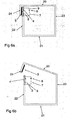
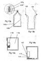
- the first package member may form a container body, such as a bottle or a jar, and the second package member may form a closure member, such as a cap.
- the first package member forms a closure member and the second package member forms a container body.
- the exact choice of which part of the package that forms the first and the second portion (or member) depends amongst others on the materials chosen for the different parts. If the container body is made of paper it is often the available area that determines where the active surfaces are arranged. If the container body is made of glass and the cap is made of plastic, it may be convenient to provide the cap with the necessary circuitry and to leave the container body essentially unchanged compared to a conventional glass bottle with plastic cap. If the bottle is made of plastic it may be convenient to provide the bottle neck with the necessary circuitry.
- a screw cap is usually rather well aligned with the bottle neck which opens for the possibility to provide the bottle neck with some parts and the cap with other parts of the circuitry.
- a portion of at least one of said active surfaces may be exposed and adapted to be covered by said adhesive. In this way the electrically weakable adhesive will in itself provide the conductive bridge to this active surface.
- At least a portion of the first active surface and at least a portion of the second active surface are exposed and adapted to be covered by said adhesive. In this way the electrically weakable adhesive will in itself provide the conductive bridge to both active surfaces.
- the active surfaces may be shaped such that a projection of the first active surface on the surface of the carrier layer essentially surrounds a projection of the second active surface on the surface of the carrier layer. In this way the area in which the electrically weakable adhesive will be broken or weakened will be relatively large compared to the size of the active surfaces. In this way the energy losses due to resistance in the active surfaces will be minimized. It will furthermore provide a rather concentrated weakening of the adhesive, which will facilitate the opening of the package.
- a projection of the first active surface on the first surface and a projection of the second active surface on the first surface may at least partly overlap each other, wherein the laminate structure further comprises an insulating layer provided between the first and second active surfaces at least at the overlap.
- the first active surface may be formed as a closed loop with its projection on the surface of the first carrier layer surrounding the projection of the second active surface on the surface of the first carrier layer, wherein the second active surface has a connecting portion extending out of the closed loop of the first active surface, and wherein the electrically insulating layer separates the connecting portion from the first active surface.
- the electrical potential will be bridged by the electrically weakable adhesive to the first active surface all the way around the second active surface. This will give a relatively large weakened area compared to the size of the second active surface.
- the package may further comprise an electrically weakable adhesive bridging said distance between the active surfaces, and adapted to be located between the active surfaces and a second carrier layer. It may, e.g., be noted that packages may be sold to a food producer with active surfaces provided on the packages but without any electrically weakable adhesive thereon. The electrically weakable adhesive may then be applied when the package is to be closed.
- the package may further comprise a non electrically weakable adhesive arranged as a layer adapted to be located between the electrically weakable adhesive and a second carrier layer.
- a non electrically weakable adhesive arranged as a layer adapted to be located between the electrically weakable adhesive and a second carrier layer.
- the package may further comprise a second carrier layer adhered to the first carrier layer and the active surfaces by said electrically weakable adhesive or said non electrically weakable adhesive.
- the invention may also be said to involve a method comprising; providing a package body comprising a first portion and a second portion adapted to be connected to each other by at least one adhesion area and thereby keep the package closed, applying an electrically weakable adhesive to the at least one adhesion area and connecting the first and second portions to each other in the at least one adhesion area and thereby closing the package.
- a package provided with, e.g., flap portions or an integrated lid is conveniently closed.
- the invention may also be said to involve a method comprising; providing a first package member and a second package member adapted to be connected to each other by at least one adhesion area and thereby form a closed package, applying an electrically weakable adhesive to the at least one adhesion area and connecting the first package member to the second package member in the at least one adhesion area and thereby closing the package.
- a package formed of two or more separate package members such as a bottle and a cap or a jar and a lid, is conveniently closed.
- the first and the second portions of the package or the first package member and the second package member are connected to each other with the electrically weakable adhesive. In this way, no extra adhesive is needed to close the package.
- first and the second portions of the package or the first package member and the second package member are connected to each other with a second adhesive that do not have to be electrically weakable. In this way, it is possible to pre-manufacture parts of the structure.
- the methods may further comprise applying a voltage across the electrically weakable adhesive. In this way, the bond of the electrically weakable adhesive is weakened or broken as discussed in detail above.
- the method may further comprise the opening of the package by separating the first package portion or member from the second package portion or member. In this way, the weakened bond of the electrically weakable adhesive is broken and the package is easily opened.
- the packages described in the following make use of an electrically weakable adhesive material.
- the inventive packages are provided with two active surfaces acting as electron and/or ion emitter and receiver connected with a bonding layer formed by the electrically weakable adhesive material.
- the bonding layer possesses adhesive properties and conductive properties. When a voltage is applied between the active surfaces and current flows through the bonding layer, bonds formed in or between the bonding layer and at least one of the active surfaces are broken or weakened. Thus, the bonding layer forms an electrically weakable adhesive.
- the electrically weakable adhesive may bridge the complete distance between the active layers but may also be completed with additional layers of other materials capable of performing the necessary electrical and/or mechanical connection.
- Such materials may be conventional non electrically conductive adhesives, polymers, varnishes, or the like, or electrically conductive versions of respective material.
- the electrically weakable material and different basic configurations of the active surfaces will initially be discussed in detail separately from the specific designs of the packages.
- the different designs of the packages will thereafter be discussed in detail.
- the design of the package will be discussed in combination with a specific kind of basic configuration. It should however be noted that this is for exemplifying purposes and that the different basic configurations may be combined with the different designs of the packages.
- the bonding layer is composed of a composition possessing both matrix functionality and electrolyte functionality.
- the matrix and the electrolyte functionalities may be formed by a single phase or several separate phases.
- the matrix functionality provides the adhesive properties necessary to bind surfaces to each another mechanically or chemically.
- the matrix functionality may be provided by polymers, polymer resins or fibres that possess adhesive properties.
- the electrolyte functionality provides the ion conductivity necessary to support a faradic reaction, i.e. an electrochemical reaction in which a material is oxidized or reduced, or some other chemical/physical reaction.
- the materials are preferably chosen and designed in such a way that the reaction occurs at the interface between one or both of the active surfaces and the bonding layer.
- the bonding layer may be designed such that the reaction will occur within the bonding layer. This may, e.g., be accomplished by providing islands of a material with electrolyte functionality within the matrix material.
- the electrolyte functionality may be provided by adding a salt to the material or by modifying the polymer so that it includes ion-coordinating moieties.
- the electrically weakable adhesive used in the inventive packages may be the electrochemically disbondable composition ElectRelease TM supplied by EIC laboratories and disclosed in more detail in US 6,620,308 .
- Fig 1a-1c shows a common basic structure with three different alternatives of how to apply the electrical energy to break or weaken the bond of the bonding layer.
- the basic structure comprises a first carrier layer 1 and a second carrier layer 2.
- a first active layer 3 is laminated on the first carrier layer 1.
- a second active layer 4 is laminated on the second carrier layer 2.
- the active layers are bonded together by a bonding layer 5, comprising an electrically weakable adhesive.
- the electrical potential difference between the active layers 3, 4 is adapted to be provided by an external source 6 of electrical energy (indicated by the + and - signs).
- This external source may, e.g., be a battery provided in a handheld device, or a battery being attached to the package and connectable to the active layers 3, 4.
- One or several batteries can, e.g., be printed on one of the carrier layer and connected to the active surfaces.
- the two active layers 3, 4 may, but need not, be formed of the same material.
- the current applied may be in the form of direct current or alternating current.
- a direct current is preferably used to weaken the bonds in the bonding layer 5 or between one of the active surfaces 3 or 4 and the bonding layer 5.
- An alternating current is preferably used to weaken the bonds in the bonding layer 5 or between both of the active layers 3, 4 and the bonding layer 5.
- the electrical potential difference between the active layers 3, 4 is adapted to be provided by making the active layers 3, 4 of different materials with different electrode potentials. If the two active layers 3, 4 are connected, e.g. by moving a switch 7 to a position where it connects the two layers 3, 4, a closed circuit is formed and current will flow through the bonding layer 5, thereby causing the adhesive bond to break or weaken.
- copper and graphite can be used as active layers 3, 4 with different potentials. This design will create a flow of direct current between the active layers 3, 4 via the bonding layer 5.
- the electrical potential difference between the active layers 3, 4 is provided by supplying electro magnetic waves, e.g. radio waves, to the package.
- the active layers 3, 4 or a separate member 8 connected to the active layers 3, 4 may be adapted to be subjected to the electro magnetic waves and transform this wave to an electrical potential difference between the active layers 3, 4.
- the AC voltage generated by the electro magnetic waves can be used directly or transformed to DC voltage by a rectifier, e.g. a half-wave rectifier or a full-wave rectifier, connected to the active surfaces.
- the member 8 may e.g. be an antenna or coil. In this design the two active layers 3, 4 may, but need not, be formed of the same material.
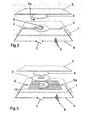
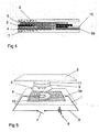
- Fig 2-5 show examples wherein the active surfaces are arranged on the same side on a carrier layer.
- the different layers are for clarity reasons illustrated at a distance from each other. However, it is apparent that in practice the layers forms a laminated structure. From the description below it will follow in which cases the different disclosed layers need to be in direct contact with each other and when there may be one or more additional, non-disclosed layers between the disclosed layers. It may also be noted that in direct contact may dependent upon the situation mean in mechanical contact or in electrical contact. Furthermore, the teachings concerning different ways of applying the voltage discussed in fig 1a-c are applicable also for the embodiments of fig 2-5 .
- Fig 2 shows an example wherein the active surfaces 3, 4 are arranged on the same side of the bonding layer, instead of being provided as two separate layers 3, 4 on either side of the bonding layer 5 as in fig 1a-c .
- the structure comprises two carrier layers 1, 2 that are to be delaminated.
- the carrier layers 1, 2 may, e.g., be made of paper, paper board or plastic, but other materials are contemplated.
- the active surfaces 3, 4 are arranged on one side of the bonding layer 5 and are separated from each other a distance d along the surface 5a of the carrier layer 1.
- the active surfaces 3, 4 may be applied to the first carrier layer 1 using any conventional method, they may e.g. be printed or laminated onto the carrier layer 1.
- the active surfaces 3, 4 may be made of any conductive material, e.g. metal ink or foil.
- the bonding layer 5 is provided between respective active surface 3, 4 and the second carrier layer 2, thereby bonding the active surfaces 3, 4 to the second carrier layer 2 and in turn thereby bonding the two carrier layers 1, 2 to each other.
- the bonding layer 5 typically reaches the first carrier layer 1 in the small accessible area formed by the gap or distance d between the active surfaces 3, 4.
- one of the active surfaces 3 has an area of distribution formed as an open half-circle partially enclosing the other active surface 4.
- This other active surface 4 has an area of distribution formed as a circle.
- the two active surfaces 3, 4 form a gap formed as a part of a ring, in this case a part of a circular ring, having a width defined by the above mentioned distance d.
- the active surfaces 3, 4 are also connected or connectable to each other via a circuit 9 comprising an external power supply 6 and a switch 7.
- the accessible area of the first carrier layer 1 between the active surfaces 3, 4 may be made so small that even if the bonding layer 5 reaches the first carrier layer 1, the force needed to break the bond between this accessible area and the bonding layer 5 is negligible.
- the power supply 6 can, e.g., be at least one battery that is printed or laminated on the carrier layer 1 and connected to the active surfaces 3, 4. In this way, the battery 6 and the active surfaces 3, 4 can be printed or laminated on the carrier layer in the same process step. In order to increase the power supply, several batteries can be printed on the carrier layer 1 and connected to the active surfaces. This enables all batteries and the active surfaces to be printed on the carrier layer in the same process step, which facilities the manufacturing of the structure.
- the active surfaces 3, 4 are formed of different materials with different potentials.
- the external power supply 6 may be dispensed with.
- the circuit 9 When the circuit 9 is closed by the switch 7, current will flow between the active surfaces 3, 4 via the bonding layer 5, which will cause the bonds in the bonding layer 5 or between the bonding layer 5 and one or both of the active surfaces 3, 4 to break or to weaken.
- Fig 3 and 4 show yet another example of a kind similar to the one shown in fig 2 .
- the active surfaces 3, 4 are separated out of the plane by an insulating layer 10, but are still on the same side of the bonding layer 5 compared to the second carrier layer 2.
- the first active surface 3 is electrically connected to a connector 3a that formed part of the first active surface 3 in the embodiment of fig 2 .
- the insulating layer 10 separates the conducting elements and protects them from tear and wear.
- the connector 3a is in contact with the first active surface 3, but there is no direct connection between the connector 3a and the second active surface 4.
- the second active surface 4 is provided on the carrier layer 1 as in the embodiment of fig 2 .
- the insulating layer 10 is provided on this structure.
- Above the insulating layer 10 is the first active surface 3 arranged, and finally on top of this is the bonding layer 5 arranged. Since the first and second active surfaces 3, 4 are separated out of the plane, the first active surface 3 may be formed as a circular member completely surrounding the circular end portion of the second active surface 4.
- the active surfaces 3, 4 and the insulating layer 10 provides a gap between the active surfaces 3, 4 adapted to be bridged by the bonding layer 5.
- the bonding layer 5 may extend all the way from the second carrier layer 2 to the first carrier layer 1 and thereby provide a direct adhesion between the first and second carrier layer 1, 3.
- the active surfaces 3, 4 are also connected or connectable to each other via a circuit 9 comprising an external power supply 6 and a switch 7.
- the accessible area of the first carrier layer 1 between the active surfaces 3, 4 may be made so small that even if the bonding layer 5 reaches the first carrier layer 1, the force needed to break the bond between this accessible area and the bonding layer 5 is negligible.
- the active surfaces 3, 4 are formed of different materials with different potentials.
- the external power supply 6 may be dispensed with.
- the circuit 9 When the circuit 9 is closed by the switch 7, current will flow between the active surfaces 3, 4 via the bonding layer 5, which will cause the bonds in the bonding layer 5 or between the bonding layer 5 and one or both of the active surfaces 3, 4 to break or to weaken.
- Fig 5 shows an alternative example to the one shown in fig 3 and 4 , wherein the bonding layer 5 is adapted to carry a second bonding layer 11.
- This second bonding layer 11 may be formed of an adhesive that do not have to be conductive or electrically weakable.
- This second bonding layer it is possible to pre-manufacture the first carrier layer 1 with the active surfaces 3, 4 and the bonding layer 5, and then finally apply a second bonding layer 11 on the electrically weakable bonding layer 5 when the second carrier layer 2 is to be fastened to the first carrier layer 1.
- This additional bonding layer 11 may also be used in the design disclosed in fig 2 .
- Respective active surface/layer may be arranged directly or indirectly via a laminating layer or the like on respective carrier layers.
- the active layer may in it self form both active surface and carrier layer.
- the active surfaces may be separated in the plane and/or out of the plane.
- an insulating layer e.g. varnish
- Insulating layers may also be used to separate conductive elements, such as active surfaces, from the carrier layer in cases when the carrier layer is conductive. Additional conductors may be arranged e.g. between the bonding layer and the second carrier layer in order to increase the conductivity in the plane of the structure.
- the active surfaces are electrically conductive surfaces, conductors, and are preferably coated, printed or laminated on at least one carrier layer. However, if the carrier layers are electrically conductive, no extra active surfaces are needed.
- the active surfaces may be composed of any electrically conductive material, e.g. copper, aluminium or graphite.
- the active surfaces may for example be in the form of a metal ink.
- the carrier layer represent surfaces that are to be delaminated by the electrical force and can be of any conductive or non-conductive material, e.g. paper, paper board, glass, metal, wood, moulded fibres or plastic.
- Two opposite sides of an opening of a package may for example represent a first and a second carrier layer. This will be discussed in more detail below.
- the carrier layers are formed of carton boards and the active layers are formed of an aluminium foil with oxide.
- the active surfaces are moisturized with a salt solution and bonded together using a composition comprising polyurethane.
- a voltage is applied over the laminate structure, the aluminium oxide on the positively charged foil dissolves whereby the laminate is broken.
- the electrical force may be applied by any of the methods referred to above and in fig 1a-c .
- the delaminating of the structure can be made easier with a built-in strain in the structure.
- a rubber ring can be used to form an elastic strain.
- the electrically weakable adhesive can be applied around the rubber ring and the rubber ring can be pressed together when curing. This can for example be used in order to create "self opening" packages, wherein the product pops up when the user weakens or breaks the bonds in the adhesive by the application of a voltage.
- the delaminating material structure comprising carrier layers, active surfaces and an electrically weakable adhesive as described above may be used whenever the strength of a seal needs to be released, for example in the construction of packages.
- the packages may be opened by the application of a voltage. It can be used in all kinds of packages, such as cans, jars, bottles, cartons and blister packages. It may also be used together with all kinds of materials, such as paper, paper board, glass, metal, wood, moulded fibres or plastic. Two opposite sides of an opening of a package may represent a first and second carrier layer and the electrically weakable adhesive described above may be arranged between the carrier layers.
- the controlled delaminating material may be used for collation of products in transit or handling and subsequent separation of the products, for separating packages bonded together and for tamper-proofing goods. It may also be used to limit or change the properties of a product before it is purchased in order to prevent theft. Collation of products, tamper-proofing a product or preventing theft of a product may be done by binding existing parts or elements of the product or products together or by binding additional elements to the product or products, using the controlled delaminating material.
- Fig 6-14 discloses examples of uses and applications in different kind of packages.
- Fig 6a-b discloses in cross-section a package in accordance with the invention being provided with a closure adapted to be opened using the electrically weakable laminated structure described above.
- the package comprises a top panel 20, a bottom panel 21, a front panel 22, a back panel 23 and two side panels (in front of and behind the cross-section of fig 6a-b ).
- a closure flap 24 is connected to or integrally formed with the top panel 20. The closure flap 24 is folded relative to the top panel 20, extends along a portion of the front panel 22 and is fastened to the front panel 22 using the electrically weakable laminated structure described above.
- Two active surfaces 3, 4 are arranged side by side, but not in direct contact, on one side of the opening closed by the top panel 20.
- the active surfaces 3, 4 are arranged on the outside of the front panel 22 facing the closure flap 24.
- a bonding layer 5 is applied between the active surfaces 3, 4 and the closure flap 24, thereby bonding the active surfaces 3, 4 to the closure flap 24.
- An electrical circuit 9 is provided to electrically connect the active surfaces 3, 4.
- the circuit is schematically drawn to include a switch 7 and a voltage supply 6. This has been discussed in more detail with reference to fig 1a-c .
- the switch 7 In fig 6a , the switch 7 is open, no current flows through the bonding layer 5 and the closure flap 24 remains bonded to the active surfaces 3, 4 and, consequently, to the front panel 22. In fig 6b , the switch 7 is closed, a closed circuit is formed, current flows through the bonding layer 5, thereby causing bonds in the bonding layer 5 or between the bonding layer 5 and one or both of the active surfaces 3, 4 to break or to weaken, whereby the package may easily be opened.
- Fig 6 is a schematic picture showing the principle.
- the circuit 9 and the switch 7 may be arranged such that the user that wants to open the package presses a button arranged on the outside of the package, which causes the switch to close and the bonds in the bonding layer to break or to weaken.
- the circuit can comprise several switches, such as two switches, so that the user who wants to open the package has to press two buttons, simultaneously or in sequence, in order to be able to open the package.
- the energy needed to break or weaken the bonds in the bonding layer may e.g. be applied by any of the methods described above and in fig 1a-c .
- insulating layers may be arranged in order to separate the active surfaces 3, 4 out of the plane as described above with reference to fig 2-5 and a conventional non-conducting adhesive may be arranged between the bonding layer 5 and the closure flap 24. It may also be noted that, in contrast to fig 6 where the front panel 22 constitutes the first carrier layer 1 and the closure flap 24 constitutes the second carrier layer 2, the closure flap 24 may constitute the first carrier layer 1 and the front panel 22 of the package may constitute the second carrier layer 2.
- Fig 7 shows another embodiment of a package adapted to be opened by the application of an electrical force, which package comprises two parts, a container 30, which is adapted to receive a product, and a cap 31.
- the package may for example be a bottle, but any kind of package is possible.
- the active surfaces 3, 4 are arranged at a distance from each other on the surface of the cap 31 facing the container 30.
- a bonding layer 5 is applied between the active surfaces 3, 4 and the surface of the container 30 facing the cap 31.
- the bonding layer 5 glues the cap 31 to the container 30.
- the active layers 3, 4 are connected by a circuit 9 comprising a switch 7 and a voltage supply 6. When the switch 7 is open, no current flows between the active surfaces 3, 4 or through the bonding layer 5 and the cap remains glued to the container 30.
- the switch 7 is closed and current flows through the bonding layer 5, the bonds in the bonding layer 5 or between the bonding layer 5 and one or both of the active surfaces 3, 4 are broken or weakened, whereby the container 30
- the energy needed to break or weaken the bonds in the bonding layer may, e.g., be applied by any of the methods described above and in fig 1a-c .
- insulating layers may be arranged in order to separate the active surfaces 3, 4 out of the plane as described above with reference to fig 2-5 and a conventional non-conducting adhesive may be arranged between the bonding layer 5 and the container 30 or the cap 31.
- a conventional non-conducting adhesive may be arranged between the bonding layer 5 and the container 30 or the cap 31. It may also be noted that, in contrast to fig 7 where the cap 31 constitutes the first carrier layer 1 and the container 30 constitutes the second carrier layer 2, the container 30 may constitute the first carrier layer 1 and the cap 31 may constitute the second carrier layer 2.
- the inner envelope surface of the cap 31 and the outer envelope surface of the neck of the container 30 may be threaded, whereby the cap is screwed on the container.
- the threads may extend about the complete circumference of the neck or only partly as in a bayonet connection often used in glass jars and metal lids.
- the controlled delaminating material may serve as a tamper proof or as a easily breakable sealing layer.
- a bottle 80 is provided with a foil 84 fastened to the bottle mouth 83 using a bonding layer 85 of an electrically weakable adhesive.
- the mouth of the bottle is provided with a surface layer 83 acting as a first active surface.
- the foil is formed of a conductive material acting as the second active surface 84.
- the foil if further provided with a flap portion 87a adapted to be folded downward along the bottle neck and to thereby contact an electric circuitry also connected to the first active layer.
- the electric circuitry may be connected to a battery or the active surfaces may be formed of materials with different electrode potentials, thereby forming an internal battery by themselves.
- the can 90 comprises a cylinder wall 90a which is arranged around a centre axis.
- the can is closed at one end of the cylinder and is at the other end provided with a lid 90b.
- the lid is connected to the can using an electrically weakable adhesive.
- the can cylinder is provided with a flange 91 facing the centre of the can.
- the lid 90b is placed on top of said flange 91.
- the flange 91 acts as or is provided with a first active surface 93 whereas the lid 90b acts as or is provided with a second active surface 95. Between the active surfaces 93, 95 is a bonding layer 94 of an electrically weakable adhesive arranged.
- the active surfaces may be connected to a voltage source or be provided by materials having different electrode potentials as discussed in detail above.
- the active surfaces and the bonding layer form a laminate structure where the layers are arranged in consecutive order; a first active layer, a bonding layer, a second active layer.
- the electrical connection may be manoeuvred using a flap 96 extending slightly outside the perimeter of the can 90.
- This flap 96 may e.g. act as a switch being connected to the active surface 95 of the lid 90b and by folding it along the envelope surface it may come into contact with the active surface 93 of the can cylinder 90a.
- a bag-in-box package is disclosed.
- the package comprises a relative stiff box 100a usually formed of paper board and a bag 100b usually formed of flexible plastic arranged inside the box 100a.
- the package in fig 13a-b is closed using an electrically weakable adhesive arranged between two active surfaces 103 and 104.
- the active surfaces is connected to electric circuitry 107a and 107b by which a closed circuit may be formed for application of a potential difference across the bonding layer arranged between the active surfaces 103 and 104.
- the electrical circuitry 107a is formed of a conductor on a flap connected to one of the active surfaces 104 and a connector portion on the outside of the box 100a.
- the circuitry may also comprise a battery.
- there are other means to provide the voltage such as by forming the active surfaces of materials with different electrode potentials, thereby forming an internal battery themselves.
- Fig 14a-b shows a package basically of the kind shown in fig 6a-b .
- the package of fig 14a-b is further provided with an additional compartment 110b.
- the additional compartment 110b is arranged inside the main compartment 110a.
- the compartments may however be arranged side by side where none of them encloses the other.
- the additional compartment 110b is provided with an opening formed of a first active surface 113 and a second active surface 114 held together by a bonding layer comprising an electrically weakable adhesive.
- the package is further provided with electrical circuitry adapted to provide electrical potential difference between the active surfaces 113 and 114.
- the electrical circuitry comprises a switch by which the electrical circuitry may be closed to form a closed circuit.
- the bond between the active layers 113 and 114 is broken such that the product inside the additional compartment 110b is introduced into the main compartment 110a.
- This may, e.g., be suitable to use when a product in the additional compartment 110b will react with the product in the main compartment 110a.
- This may, e.g., be the case with yeast or bacterial cultures that are to be added to food products or the like.
- the additional compartment may be opened first, the package is thereafter shaken to mix the product with the yeast, where after the main compartment is opened and the mixed product is emptied out of the package.
- the compartments may be arranged side by side such that they all open directly out of the package. This may, e.g., be the case where two food products are served in a ready to eat meal, where the intention is that one of the products is to be poured on top of the other, such as jam onto rice pudding or muesli into soured milk.
- the packages described above are packages forming one or more closed compartments, the inventive package may also be more or less open packages. It may also be noted that the package may not only be used as a primary package containing a product, but also as so-called secondary packages containing or enveloping primary packages. A secondary package may in turn be contained in another secondary package, whereby the scope of the invention is defined by the claims.
Abstract
Description
- The invention relates to a package comprising a first portion and a second portion adapted to be connected to each other and thereby keep the package closed, wherein the first and second portions are connected to each other by at least one adhesion area.
- The invention further relates to a package comprising a first package member adapted to co-operate with a second package member and thereby form a closed package, wherein the first package member is adapted to be connectable to the second package member by at least one adhesion area.
- The invention further relates to a method of closing and subsequent opening of a package.
- The old way of distributing products in large distribution packages, followed by repacking of the products behind the store counter in paper bags, or the like, in the amount as bought by the consumer, has almost completely disappeared. Decades ago the wide spread of the large self service stores, with pre-packed products stored on shelves, from which the consumers themselves pick the products, lead to great developments in the packaging industry.
- Today almost all consumer products are packed at the manufacturing or processing site, distributed, sold, and often also stored in the consumers' home, in one and the same package. One popular kind of package used for almost all kind of products is a box made of paperboard. Paperboard boxes are, e.g., widely used for dry food products and for small commodity items such as screws and nails. By providing an inner bag the paperboard box may also be used for liquids or for powder products, such as cocoa or dry milk. This kind of package is also widely used for cereals and similar products.
- This kind of package is often adapted to be opened by first tearing off a tearing band or strip from the paperboard box and then cutting (with a pair of scissors) the inner bag open. The tearing band often extends across the complete top surface, from side edge to side edge, and separates a front flap connected with the front side of the container from a rear flap connected to the back side of the package. The front and rear flaps are often spot glued to side flaps folded from the sides of the package underneath the front and rear flaps. When the consumer opens such a package the tear band often breaks and the tearing action need to be restarted again. Moreover, the tear band often does not separate from the flaps as intended, which makes it more difficult to open the package and which often results in that any reclosing means, such as flaps and slits, are damaged.
- Another kind of package often used as a consumer package is a bottle or jar formed of plastic or glass provided with a screw cap or snap lid formed of plastic or metal. This kind of package has an intrinsic problem relating to the compromise of providing a sufficiently low initial opening force and a sufficiently good sealing. Most caps or lids on this kind of package are fastened by threads or bayonet mount. In order to provide the necessary sealing pressure, the caps or lids must be fastened with a significant torque. Within the packaging industry there exist numerous variants concerning how to avoid the need for application of a high torque for closing the package. However, as will be discussed below, these variants introduce different drawbacks for the consumers when opening the packages, and especially at initial opening of the packages.
- One kind of package often used for jam, pickled gherkin, and the like is a glass jar with a metal lid. Such a package is often filled by hot-filling or the like in order to create a negative pressure inside the jar. This negative pressure will force the lid against the mouth of the jar and will thereby improve the quality of the sealing between the lid and jar. However, this way of creating a good seal has the drawback that it is very hard to open such a jar; when trying to rotate the lid, the negative pressure will give rise to a high friction force counteracting the intended opening action. This kind of package also requires that the jar and lid are formed of relatively rigid components in order to be able to withstand the forces involved.
- One kind of package often used for dry products, such as instant coffee, is a glass jar with a simple plastic lid. In order to provide sufficient sealing, the jar is, underneath the lid, provided with a sealing film or membrane. Such a sealing membrane is often also provided on plastic bottles for ketchup, mustard or the like, and boxes for table margarine or the like, where the lid has a snap functionality or some other functionality which is difficult to use to provide a sealing action. The film or membrane is often glued or fused to the mouth of the package. However, this kind of package suffers from the drawback that the necessary tearing off force must be sufficiently low so that the user is able to tear off the membrane and preferably in one piece, but the membrane should also be securely sealed to the mouth and it should from cost and environment aspects be as thin as possible. The result is often that the consumer has difficulties in tearing off the membrane at all or in tearing off the membrane in one piece. If the membrane is only partially torn off, it is often difficult to get rid of the remainders since any grip tab or the like has already been torn off.
- Thus, the known packages all suffer from different drawbacks when it comes to opening of the packages.
- It is well known in the art that polymer chains can be broken by the application of a voltage. This is for example discussed in a review article by G.S. Shapoval(Cathodic initiation of reactions of macromolecule formation and degradation, Theoretical and Experimental Chemistry, ).
-
US 6,620,308 B2 discloses a material for use in the airplane industry. As is evident from the published patent, the material has been developed under the supervision of the U.S. Department of the Air Force. The material is developed for use as coatings and adhesives. It is further elaborated inUS 6,620,308 that the adhesive bonds and polymeric coatings are commonly used in the assembly and finishing of manufactured goods. It is stated that adhesive bonds are used in place of mechanical fasteners, such as screw, bolts and rivets, to provide bonds with reduced machining costs and greater adaptability in the manufacturing process. It is further discussed that adhesive bonds distribute stresses evenly, reduce the risk of fatigue, and seal the joints from corrosive species. It further asserts that, similarly, polymer-based coatings are commonly applied to the exterior surface of the manufactured products. These coatings provide protective layers that seal the surface from corrosive reactants, as well as provide a painted surface that can the aesthetically pleasing. - The composition disclosed in
US 6,620,308 B2 has a matrix functionality and an electrolyte functionality, wherein the electrolyte functionality is provided by a block copolymer or a graft copolymer. The matrix functionality provides an adhesive bond to a substrate, and the electrolyte functionality provides sufficient ionic conductivity to the composition to support a faradic reaction at an interface with an electrically conductive surface in contact with the composition, whereby the adhesive bond is weakened at the interface. The composition may be a phase-separated composition having first regions of substantially matrix functionality and second regions of substantially electrolyte functionality. - It is an object of the invention to provide a package which is not associated with the above mentioned problems or by which the above mentioned problems is at least reduced.
- This object has been achieved by a package of the initially indicated kind which is characterised in that it comprises a first portion and a second portion adapted to be connected to each other and thereby keep the package closed, wherein the first and second portions are connected to each other by at least one adhesion area, wherein the adhesion area comprises an electrically weakable adhesive.
- The above object has also been achieved by a package of the initially indicated kind which is characterised in that it comprises a first package member adapted to co-operate with a second package member and thereby form a closed package, wherein the first package member is adapted to be connectable to the second package member by at least one adhesion area, wherein the adhesion area comprises an electrically weakable adhesive.
- By providing a package with a first and a second portion (or a first package member and a second package member) adhered to each other with an electrically weakable adhesive it is possible to provide packages which has hitherto not been possible to make. Furthermore, it is possible to provide packages of conventional design which are much easier to open compared to the packages of today.
- The adhesion areas are provided with an electrically weakable adhesive that possesses adhesive properties and conductive properties. The package can further be provided with at least one active surface, being electrically conducting and in contact with the electrically weakable adhesive. When a voltage is applied between the active surfaces and current flows through a bonding layer comprising the electrically weakable adhesive, bonds formed in or between the bonding layer and at least one of the active surfaces are broken and/or weakened. Thus, the bonding layer forms an electrically weakable adhesive.
- As mentioned above, glued cardboard packages are today often provided with a tear strip. With the new design of the package, there is no longer any need for such a tear strip. The package is glued together at filling of the package using an electrically weakable adhesive. When the consumer would like to open the package, a voltage is applied to the electrically weakable adhesive and the adhesive looses its adhesive force. The package is thereafter easily opened without any risk of being incorrectly torn open and without any risk of damaging any reclosure tabs/slots or the like. The package with the electrically weakable adhesive may also be designed or configured in a manner not possible today. When designing a conventional package, the designer must balance design requirements relating to erecting and closing of the container with design requirements relating to opening of the container. This often results in that the closing of the container is unnecessary complicated and still it is hard to open the container as intended. This problem is eliminated or at least greatly reduced with the new package. It is e.g. possible to design the container in a way that gives a simple erecting and closing of the container by simply using adhesive connections where connection is desired. When the user wants to open the package a voltage is applied to the electrically weakable adhesive, and the desired connections are easily released. In this way it is further possible to design the package to be as strong as possible without the need for any far-reaching compromises concerning how to still make opening of the package easy. The package is in any case simply opened by the application of a voltage to the electrically weakable adhesive.
- The package may also be provided as a semi-finished product comprising a first portion and a second portion adapted to be connected to each other and thereby keep the package closed, wherein the first and second portions are connected to each other by at least one adhesion area, wherein the adhesion areas comprises a first active surface, being electrically conducting and adapted to receive an electrically weakable adhesive, wherein the first active surface forms part of an electrical circuitry arranged to apply a voltage to said electrically weakable adhesive.
- In this configuration the package is provided with the active surface whereas the electrically weakable adhesive is adapted to be applied to the active surface when the package is to be filled and closed. The advantages of the package have been discussed in detail above with reference to the embodiment of the package with the electrically weakable adhesive applied to the adhesion area.
- Similarly, for a package with a body and a cap it is possible to provide a package which is tightly closed in distribution and which still is easily opened. The electrically weakable adhesive may, e.g., be used to secure a screw cap from unintentionally being screwed off the bottle and, after being subjected to a voltage, still easily release the cap from the bottle when the package is to be opened. This may also be used for a foil covered opening. The foil is securely fastened to the mouth of the bottle or jar using the electrically weakable adhesive. When the package is to be opened, a voltage is applied and the foil is easily removed. Thereby it is possible to even fasten the foil so securely that it is impossible to tear it off without applying a voltage. In any case it is possible to secure the foil to a greater extent than today and still make it possible to release it much easier than today. With this difference in securing power it is possible to design very thin foils, since they after application of a voltage only have to withstand any remaining tear-off resistance instead of as today where they during tear-off have to withstand the original tear-off resistance being designed to be high enough to keep the foil secured to the package during distribution.
- Similarly, this package design may also be adapted to be provided as a semi-finished product comprising a first package member adapted to co-operate with a second package member and thereby form a closed package, wherein the first package member is adapted to be connectable to the second package member by at least one adhesion area, wherein the adhesion area comprise a first active surface, being electrically conducting and adapted to receive an electrically weakable adhesive, wherein the first active surface forms part of an electrical circuitry arranged to apply a voltage to said electrically weakable adhesive.
- In this configuration the package is provided with the active surface whereas the electrically weakable adhesive is adapted to be applied to the active surface when the package is to be filled and closed. The advantages of the package has been discussed in detail above with reference to the embodiment of the package with the electrically weakable adhesive applied to the adhesion area.
- The package may further comprise a second package member adapted to co-operate with the first package member and thereby form a closed package.
- The use of electrically weakable adhesives also allows for the application of a tamper-proof feature integrally formed with the initial closure of the package. When the electrically weakable adhesive has reacted, it will no longer return to the same strong adhesive strength and it will thereby provide a tamper-proof feature.
- The voltage applied may be either alternating or direct depending upon the desired manner of weakening of the electrically weakable adhesive. The voltage may, e.g., be applied by an external source, such as a battery, by electromagnetic waves, or by designing the package with active surfaces of different materials with different potentials, thereby forming an internal battery.
- The package as defined in
claim 1 further comprises a first and a second active surface being electrically conducting and being arranged at a distance from each other and being adapted to be electrically connectable to each other via an electrical circuit, wherein the electrically weakable adhesive is bridging the distance between the first and second active surfaces. In this way it is possible to in a controlled way apply a voltage across the electrically weakable adhesive. The two active surfaces are connectable to two different electrode potentials thereby causing a voltage across the electrically weakable adhesive. As mentioned above, the voltage may be provided in a number of ways. - The electrically weakable adhesive may form a sealing layer. In this way it is possible to form a securely sealed package which still may be easily opened.
- The package may be formed of a non-conductive material. In this way the conductors, such as the active surfaces, may simply be provided as printed or laminated conductors on the non-conductive material. There will be no immediate need for more complicated laminate structures with insulating layers, etc.
- The package may be formed of paper board or of plastic. Either of these materials is preferred since it is easy to provide a connecting element or a package in paper board or in plastic. Plastic or paper board are also normally non-conducting making it easy to provide it with an electrical circuitry using, e.g., a printing or laminating technique.
- The package may comprise an internal source of electrical power adapted to be activated or connected to the conductors to in a closed electrical circuit apply voltage to respective adhesion areas. In this way the package may be opened anywhere and by anyone.
- The first active surface may be of a first material with a first electrode potential, and the second active surface may be of a second material with a second electrode potential, and wherein the first electrode potential differs from the second electrode potential. In this way the active surfaces as such will act as an internal source of electrical power and will when connected to each other via an electrical circuitry outside the electrically weakable adhesive form a closed electrical circuit applying a voltage across the electrically weakable adhesive.
- The connecting element or package may further comprise at least one printed and/or laminated battery. This is an expedient way of providing an internal source of electrical power.
- The at least one printed and/or laminated battery may be printed on a first carrier layer. This is an expedient way of providing a battery forming an internal source of power. As indicated the first carrier layer may also be used to carry one or more active surfaces. Thereby it is easy to provide a connection between the battery and the one or more active surfaces on the first carrier layer.
- The package may further comprise a first carrier layer with a first surface, the first and second active surfaces being supported by the carrier layer, wherein the first active surface is separated from the second active surface a first distance along the surface of the first carrier layer, wherein the laminate structure is adapted to receive an electrically weakable adhesive bridging said distance between the active surfaces.
- In this way it is possible to pre-manufacture parts of the structure with the active surfaces on a single carrier layer. When the package is to be closed, the electrically weakable adhesive is applied to the active surfaces and a second carrier layer is put onto the adhesive, whereby the first and second portions (or first and second members) of the package are connected to each other. This design also makes it possible to provide both active surfaces on one and the same side of the layer of the electrically weakable adhesive, and thereby on one and the same portion or package member. Such a design facilitates the provision of any circuitry, since the circuitry in such a case does not have to bridge any interface between the first and second portions (or first and second package members).
- The first active surface may be separated from the second active surface a distance in a direction of a normal to the first active surface, wherein an electrically weakable adhesive may be bridging the distance between the first and second active surfaces. One advantage with such a design is that it is relatively easy to provide a large contact interface between the electrically weakable adhesive and the active surfaces. Moreover, the distance bridged by the electrically weakable adhesive can be kept the same over a large interface, which will give a controlled disbonding.
- This design may, e.g., also be used where the voltage is applied by an external voltage. The first active surface is provided with a first connector portion and the second active surface is provided with a second connector portion, whereby an external voltage source is connected to the connector portions and a voltage is applied across the electrically weakable adhesive.
- The first portion or the first package member may form the first carrier layer. The first package member may form a container body, such as a bottle or a jar, and the second package member may form a closure member, such as a cap. However, in an alternative the first package member forms a closure member and the second package member forms a container body. The exact choice of which part of the package that forms the first and the second portion (or member) depends amongst others on the materials chosen for the different parts. If the container body is made of paper it is often the available area that determines where the active surfaces are arranged. If the container body is made of glass and the cap is made of plastic, it may be convenient to provide the cap with the necessary circuitry and to leave the container body essentially unchanged compared to a conventional glass bottle with plastic cap. If the bottle is made of plastic it may be convenient to provide the bottle neck with the necessary circuitry. A screw cap is usually rather well aligned with the bottle neck which opens for the possibility to provide the bottle neck with some parts and the cap with other parts of the circuitry.
- A portion of at least one of said active surfaces may be exposed and adapted to be covered by said adhesive. In this way the electrically weakable adhesive will in itself provide the conductive bridge to this active surface.
- At least a portion of the first active surface and at least a portion of the second active surface are exposed and adapted to be covered by said adhesive. In this way the electrically weakable adhesive will in itself provide the conductive bridge to both active surfaces.
- The active surfaces may be shaped such that a projection of the first active surface on the surface of the carrier layer essentially surrounds a projection of the second active surface on the surface of the carrier layer. In this way the area in which the electrically weakable adhesive will be broken or weakened will be relatively large compared to the size of the active surfaces. In this way the energy losses due to resistance in the active surfaces will be minimized. It will furthermore provide a rather concentrated weakening of the adhesive, which will facilitate the opening of the package.
- A projection of the first active surface on the first surface and a projection of the second active surface on the first surface may at least partly overlap each other, wherein the laminate structure further comprises an insulating layer provided between the first and second active surfaces at least at the overlap. By providing active surfaces with overlaps and insulating layers there between it is possible to optimise the shape of the electrically weakened area, without having to be limited by separation in the plane of the carrier layer.
- The first active surface may be formed as a closed loop with its projection on the surface of the first carrier layer surrounding the projection of the second active surface on the surface of the first carrier layer, wherein the second active surface has a connecting portion extending out of the closed loop of the first active surface, and wherein the electrically insulating layer separates the connecting portion from the first active surface. In this way the electrical potential will be bridged by the electrically weakable adhesive to the first active surface all the way around the second active surface. This will give a relatively large weakened area compared to the size of the second active surface.
- The package may further comprise an electrically weakable adhesive bridging said distance between the active surfaces, and adapted to be located between the active surfaces and a second carrier layer. It may, e.g., be noted that packages may be sold to a food producer with active surfaces provided on the packages but without any electrically weakable adhesive thereon. The electrically weakable adhesive may then be applied when the package is to be closed.
- The package may further comprise a non electrically weakable adhesive arranged as a layer adapted to be located between the electrically weakable adhesive and a second carrier layer. In this way it is possible to pre-manufacture the structure with active surfaces and electrically weakable adhesive and then to apply a conventional adhesive on top of this when the package is closed for the first time. When the package is to be opened the electrically weakable adhesive is weakened and the conventional adhesive will be released together with the portion or package member not carrying the active surfaces. It is also contemplated to provide two layers of electrically weakable adhesive, one layer in the pre-manufacturing step and a second layer when the package is closed.
- The package may further comprise a second carrier layer adhered to the first carrier layer and the active surfaces by said electrically weakable adhesive or said non electrically weakable adhesive.
- The invention may also be said to involve a method comprising; providing a package body comprising a first portion and a second portion adapted to be connected to each other by at least one adhesion area and thereby keep the package closed, applying an electrically weakable adhesive to the at least one adhesion area and connecting the first and second portions to each other in the at least one adhesion area and thereby closing the package. In this way a package provided with, e.g., flap portions or an integrated lid is conveniently closed.
- The invention may also be said to involve a method comprising; providing a first package member and a second package member adapted to be connected to each other by at least one adhesion area and thereby form a closed package, applying an electrically weakable adhesive to the at least one adhesion area and connecting the first package member to the second package member in the at least one adhesion area and thereby closing the package. In this way, a package formed of two or more separate package members, such as a bottle and a cap or a jar and a lid, is conveniently closed.
- In one embodiment, the first and the second portions of the package or the first package member and the second package member are connected to each other with the electrically weakable adhesive. In this way, no extra adhesive is needed to close the package.
- In another embodiment, the first and the second portions of the package or the first package member and the second package member are connected to each other with a second adhesive that do not have to be electrically weakable. In this way, it is possible to pre-manufacture parts of the structure.
- The methods may further comprise applying a voltage across the electrically weakable adhesive. In this way, the bond of the electrically weakable adhesive is weakened or broken as discussed in detail above.
- The method may further comprise the opening of the package by separating the first package portion or member from the second package portion or member. In this way, the weakened bond of the electrically weakable adhesive is broken and the package is easily opened.
- The invention will by way of example be described in more detail with reference to the appended schematic drawings, which shows a presently preferred embodiment of the invention.
-
Fig 1a-c shows a first basic structure in which different layers are connected to each other using an electrically weakable adhesive, wherein the three figures indicate three different alternatives of how an electrical energy may be applied in order to weaken the adhesive. -
Fig 2 shows in an exploded view a first example of a second basic structure with the active surfaces arranged on the same side of the adhesive layer. -
Fig 3 shows in an exploded view a second example of the second basic structure. -
Fig 4 shows a cross-section of the structure infig 3 . -
Fig 5 shows in an exploded view of a third example of the second basic structure. -
Fig 6a shows in cross-section a package in accordance with the invention. -
Fig 6b shows in cross-section the package offig 6a when opened. -
Fig 7 shows a portion of a bottle neck provided with a screw cap. -
Fig 8a shows a bottle provided with a sealing foil. -
Fig 8b shows in enlargement a portion of the bottle offig 8a . -
Fig 9 shows the bottle offig 8a with the foil partly removed. -
Fig 10a-b show a can with a lid. -
Fig 11 shows a number of cans arranged side by side. -
Fig 12 is a cross-section showing the connection between the lid and the can body. -
Fig 13a-b shows a bag-in-box package. -
Fig 14a-b shows a package provided with a secondary compartment for a secondary product. - The packages described in the following make use of an electrically weakable adhesive material. The inventive packages are provided with two active surfaces acting as electron and/or ion emitter and receiver connected with a bonding layer formed by the electrically weakable adhesive material. The bonding layer possesses adhesive properties and conductive properties. When a voltage is applied between the active surfaces and current flows through the bonding layer, bonds formed in or between the bonding layer and at least one of the active surfaces are broken or weakened. Thus, the bonding layer forms an electrically weakable adhesive.
- In the following, the electrically weakable adhesive may bridge the complete distance between the active layers but may also be completed with additional layers of other materials capable of performing the necessary electrical and/or mechanical connection. Such materials may be conventional non electrically conductive adhesives, polymers, varnishes, or the like, or electrically conductive versions of respective material.
- The electrically weakable material and different basic configurations of the active surfaces will initially be discussed in detail separately from the specific designs of the packages. The different designs of the packages will thereafter be discussed in detail. In some cases the design of the package will be discussed in combination with a specific kind of basic configuration. It should however be noted that this is for exemplifying purposes and that the different basic configurations may be combined with the different designs of the packages.
- According to one example the bonding layer is composed of a composition possessing both matrix functionality and electrolyte functionality. The matrix and the electrolyte functionalities may be formed by a single phase or several separate phases.
- The matrix functionality provides the adhesive properties necessary to bind surfaces to each another mechanically or chemically. The matrix functionality may be provided by polymers, polymer resins or fibres that possess adhesive properties.
- The electrolyte functionality provides the ion conductivity necessary to support a faradic reaction, i.e. an electrochemical reaction in which a material is oxidized or reduced, or some other chemical/physical reaction. The materials are preferably chosen and designed in such a way that the reaction occurs at the interface between one or both of the active surfaces and the bonding layer. Alternatively the bonding layer may be designed such that the reaction will occur within the bonding layer. This may, e.g., be accomplished by providing islands of a material with electrolyte functionality within the matrix material. The electrolyte functionality may be provided by adding a salt to the material or by modifying the polymer so that it includes ion-coordinating moieties.
- The electrically weakable adhesive used in the inventive packages may be the electrochemically disbondable composition ElectRelease ™ supplied by EIC laboratories and disclosed in more detail in
US 6,620,308 . -
Fig 1a-1c shows a common basic structure with three different alternatives of how to apply the electrical energy to break or weaken the bond of the bonding layer. - The basic structure comprises a
first carrier layer 1 and asecond carrier layer 2. A firstactive layer 3 is laminated on thefirst carrier layer 1. A secondactive layer 4 is laminated on thesecond carrier layer 2. The active layers are bonded together by abonding layer 5, comprising an electrically weakable adhesive. - In
fig 1a , the electrical potential difference between theactive layers external source 6 of electrical energy (indicated by the + and - signs). This external source may, e.g., be a battery provided in a handheld device, or a battery being attached to the package and connectable to theactive layers active layers active surfaces active surfaces bonding layer 5. This will cause the bonds in thebonding layer 5 or between thebonding layer 5 and one or both of theactive surfaces bonding layer 5 or between one of theactive surfaces bonding layer 5. An alternating current is preferably used to weaken the bonds in thebonding layer 5 or between both of theactive layers bonding layer 5. - In
fig 1b , the electrical potential difference between theactive layers active layers active layers switch 7 to a position where it connects the twolayers bonding layer 5, thereby causing the adhesive bond to break or weaken. For example, copper and graphite can be used asactive layers active layers bonding layer 5. - In
fig 1c , the electrical potential difference between theactive layers active layers separate member 8 connected to theactive layers active layers member 8 may e.g. be an antenna or coil. In this design the twoactive layers -
Fig 2-5 show examples wherein the active surfaces are arranged on the same side on a carrier layer. Infig 2, 3 and5 , the different layers are for clarity reasons illustrated at a distance from each other.
However, it is apparent that in practice the layers forms a laminated structure. From the description below it will follow in which cases the different disclosed layers need to be in direct contact with each other and when there may be one or more additional, non-disclosed layers between the disclosed layers. It may also be noted that in direct contact may dependent upon the situation mean in mechanical contact or in electrical contact. Furthermore, the teachings concerning different ways of applying the voltage discussed infig 1a-c are applicable also for the embodiments offig 2-5 . -
Fig 2 shows an example wherein theactive surfaces separate layers bonding layer 5 as infig 1a-c . The structure comprises twocarrier layers active surfaces bonding layer 5 and are separated from each other a distance d along thesurface 5a of thecarrier layer 1. - The
active surfaces first carrier layer 1 using any conventional method, they may e.g. be printed or laminated onto thecarrier layer 1. Theactive surfaces bonding layer 5 is provided between respectiveactive surface second carrier layer 2, thereby bonding theactive surfaces second carrier layer 2 and in turn thereby bonding the twocarrier layers bonding layer 5 typically reaches thefirst carrier layer 1 in the small accessible area formed by the gap or distance d between theactive surfaces fig 2 , one of theactive surfaces 3 has an area of distribution formed as an open half-circle partially enclosing the otheractive surface 4. This otheractive surface 4 has an area of distribution formed as a circle. The twoactive surfaces - The
active surfaces circuit 9 comprising anexternal power supply 6 and aswitch 7. - When a voltage is applied between the
active surfaces switch 7, current will flow between theactive surfaces bonding layer 5. This will cause the bonds in thebonding layer 5 or between thebonding layer 5 and one or both of theactive surfaces first carrier layer 1 between theactive surfaces bonding layer 5 reaches thefirst carrier layer 1, the force needed to break the bond between this accessible area and thebonding layer 5 is negligible. - The
power supply 6 can, e.g., be at least one battery that is printed or laminated on thecarrier layer 1 and connected to theactive surfaces battery 6 and theactive surfaces carrier layer 1 and connected to the active surfaces. This enables all batteries and the active surfaces to be printed on the carrier layer in the same process step, which facilities the manufacturing of the structure. - In an alternative example to the one shown in
fig 2 , theactive surfaces external power supply 6 may be dispensed with. When thecircuit 9 is closed by theswitch 7, current will flow between theactive surfaces bonding layer 5, which will cause the bonds in thebonding layer 5 or between thebonding layer 5 and one or both of theactive surfaces -
Fig 3 and4 show yet another example of a kind similar to the one shown infig 2 . In the example offig 3 and4 , theactive surfaces layer 10, but are still on the same side of thebonding layer 5 compared to thesecond carrier layer 2. The firstactive surface 3 is electrically connected to aconnector 3a that formed part of the firstactive surface 3 in the embodiment offig 2 . - The insulating
layer 10 separates the conducting elements and protects them from tear and wear. Theconnector 3a is in contact with the firstactive surface 3, but there is no direct connection between theconnector 3a and the secondactive surface 4. - The second
active surface 4 is provided on thecarrier layer 1 as in the embodiment offig 2 . The insulatinglayer 10 is provided on this structure. Above the insulatinglayer 10 is the firstactive surface 3 arranged, and finally on top of this is thebonding layer 5 arranged. Since the first and secondactive surfaces active surface 3 may be formed as a circular member completely surrounding the circular end portion of the secondactive surface 4. Theactive surfaces layer 10 provides a gap between theactive surfaces bonding layer 5. Thebonding layer 5 may extend all the way from thesecond carrier layer 2 to thefirst carrier layer 1 and thereby provide a direct adhesion between the first andsecond carrier layer - The
active surfaces circuit 9 comprising anexternal power supply 6 and aswitch 7. - When a voltage is applied between the
active surfaces switch 7, current will flow between theactive surfaces bonding layer 5. This will cause the bonds in thebonding layer 5 or between thebonding layer 5 and one or both of theactive surfaces first carrier layer 1 between theactive surfaces bonding layer 5 reaches thefirst carrier layer 1, the force needed to break the bond between this accessible area and thebonding layer 5 is negligible. - In an alternative example to the one shown in
fig 3 and4 , theactive surfaces external power supply 6 may be dispensed with. When thecircuit 9 is closed by theswitch 7, current will flow between theactive surfaces bonding layer 5, which will cause the bonds in thebonding layer 5 or between thebonding layer 5 and one or both of theactive surfaces -
Fig 5 shows an alternative example to the one shown infig 3 and4 , wherein thebonding layer 5 is adapted to carry asecond bonding layer 11. Thissecond bonding layer 11 may be formed of an adhesive that do not have to be conductive or electrically weakable. By providing this second bonding layer it is possible to pre-manufacture thefirst carrier layer 1 with theactive surfaces bonding layer 5, and then finally apply asecond bonding layer 11 on the electricallyweakable bonding layer 5 when thesecond carrier layer 2 is to be fastened to thefirst carrier layer 1. Thisadditional bonding layer 11 may also be used in the design disclosed infig 2 . - An artisan will realise that there exists several alternatives to and combinations of the above disclosed examples. A brief discussion of some these alternatives follow hereinafter.
- Respective active surface/layer may be arranged directly or indirectly via a laminating layer or the like on respective carrier layers. The active layer may in it self form both active surface and carrier layer.
- As mentioned above the active surfaces may be separated in the plane and/or out of the plane. In order to separate the active surfaces out of the plane, an insulating layer, e.g. varnish, may be used. Insulating layers may also be used to separate conductive elements, such as active surfaces, from the carrier layer in cases when the carrier layer is conductive. Additional conductors may be arranged e.g. between the bonding layer and the second carrier layer in order to increase the conductivity in the plane of the structure.
- The active surfaces are electrically conductive surfaces, conductors, and are preferably coated, printed or laminated on at least one carrier layer. However, if the carrier layers are electrically conductive, no extra active surfaces are needed. The active surfaces may be composed of any electrically conductive material, e.g. copper, aluminium or graphite. The active surfaces may for example be in the form of a metal ink.
- The carrier layer represent surfaces that are to be delaminated by the electrical force and can be of any conductive or non-conductive material, e.g. paper, paper board, glass, metal, wood, moulded fibres or plastic. Two opposite sides of an opening of a package may for example represent a first and a second carrier layer. This will be discussed in more detail below.
- In accordance with one embodiment, the carrier layers are formed of carton boards and the active layers are formed of an aluminium foil with oxide. The active surfaces are moisturized with a salt solution and bonded together using a composition comprising polyurethane. When a voltage is applied over the laminate structure, the aluminium oxide on the positively charged foil dissolves whereby the laminate is broken. The electrical force may be applied by any of the methods referred to above and in
fig 1a-c . - The delaminating of the structure can be made easier with a built-in strain in the structure. For example, a rubber ring can be used to form an elastic strain. The electrically weakable adhesive can be applied around the rubber ring and the rubber ring can be pressed together when curing. This can for example be used in order to create "self opening" packages, wherein the product pops up when the user weakens or breaks the bonds in the adhesive by the application of a voltage.
- The delaminating material structure comprising carrier layers, active surfaces and an electrically weakable adhesive as described above may be used whenever the strength of a seal needs to be released, for example in the construction of packages. By providing the material structure as described above, the packages may be opened by the application of a voltage. It can be used in all kinds of packages, such as cans, jars, bottles, cartons and blister packages. It may also be used together with all kinds of materials, such as paper, paper board, glass, metal, wood, moulded fibres or plastic. Two opposite sides of an opening of a package may represent a first and second carrier layer and the electrically weakable adhesive described above may be arranged between the carrier layers.
- Furthermore, the controlled delaminating material may be used for collation of products in transit or handling and subsequent separation of the products, for separating packages bonded together and for tamper-proofing goods. It may also be used to limit or change the properties of a product before it is purchased in order to prevent theft. Collation of products, tamper-proofing a product or preventing theft of a product may be done by binding existing parts or elements of the product or products together or by binding additional elements to the product or products, using the controlled delaminating material.
-
Fig 6-14 discloses examples of uses and applications in different kind of packages. -
Fig 6a-b discloses in cross-section a package in accordance with the invention being provided with a closure adapted to be opened using the electrically weakable laminated structure described above. - The package comprises a
top panel 20, abottom panel 21, afront panel 22, aback panel 23 and two side panels (in front of and behind the cross-section offig 6a-b ). Aclosure flap 24 is connected to or integrally formed with thetop panel 20. Theclosure flap 24 is folded relative to thetop panel 20, extends along a portion of thefront panel 22 and is fastened to thefront panel 22 using the electrically weakable laminated structure described above. - Two
active surfaces top panel 20. Theactive surfaces front panel 22 facing theclosure flap 24. Abonding layer 5 is applied between theactive surfaces closure flap 24, thereby bonding theactive surfaces closure flap 24. Anelectrical circuit 9 is provided to electrically connect theactive surfaces switch 7 and avoltage supply 6. This has been discussed in more detail with reference tofig 1a-c . - In
fig 6a , theswitch 7 is open, no current flows through thebonding layer 5 and theclosure flap 24 remains bonded to theactive surfaces front panel 22. Infig 6b , theswitch 7 is closed, a closed circuit is formed, current flows through thebonding layer 5, thereby causing bonds in thebonding layer 5 or between thebonding layer 5 and one or both of theactive surfaces -
Fig 6 is a schematic picture showing the principle. Although not shown infig. 6 , thecircuit 9 and theswitch 7 may be arranged such that the user that wants to open the package presses a button arranged on the outside of the package, which causes the switch to close and the bonds in the bonding layer to break or to weaken. In an alternative embodiment to the one shown infig. 6 , the circuit can comprise several switches, such as two switches, so that the user who wants to open the package has to press two buttons, simultaneously or in sequence, in order to be able to open the package. The energy needed to break or weaken the bonds in the bonding layer may e.g. be applied by any of the methods described above and infig 1a-c . Furthermore, insulating layers may be arranged in order to separate theactive surfaces fig 2-5 and a conventional non-conducting adhesive may be arranged between thebonding layer 5 and theclosure flap 24. It may also be noted that, in contrast tofig 6 where thefront panel 22 constitutes thefirst carrier layer 1 and theclosure flap 24 constitutes thesecond carrier layer 2, theclosure flap 24 may constitute thefirst carrier layer 1 and thefront panel 22 of the package may constitute thesecond carrier layer 2. -
Fig 7 shows another embodiment of a package adapted to be opened by the application of an electrical force, which package comprises two parts, acontainer 30, which is adapted to receive a product, and acap 31. The package may for example be a bottle, but any kind of package is possible. Theactive surfaces cap 31 facing thecontainer 30. Abonding layer 5 is applied between theactive surfaces container 30 facing thecap 31. Thebonding layer 5 glues thecap 31 to thecontainer 30. Theactive layers circuit 9 comprising aswitch 7 and avoltage supply 6. When theswitch 7 is open, no current flows between theactive surfaces bonding layer 5 and the cap remains glued to thecontainer 30. When theswitch 7 is closed and current flows through thebonding layer 5, the bonds in thebonding layer 5 or between thebonding layer 5 and one or both of theactive surfaces container 30 may easily be opened. - The energy needed to break or weaken the bonds in the bonding layer may, e.g., be applied by any of the methods described above and in
fig 1a-c . Furthermore, insulating layers may be arranged in order to separate theactive surfaces fig 2-5 and a conventional non-conducting adhesive may be arranged between thebonding layer 5 and thecontainer 30 or thecap 31. It may also be noted that, in contrast tofig 7 where thecap 31 constitutes thefirst carrier layer 1 and thecontainer 30 constitutes thesecond carrier layer 2, thecontainer 30 may constitute thefirst carrier layer 1 and thecap 31 may constitute thesecond carrier layer 2. - The inner envelope surface of the
cap 31 and the outer envelope surface of the neck of thecontainer 30 may be threaded, whereby the cap is screwed on the container. The threads may extend about the complete circumference of the neck or only partly as in a bayonet connection often used in glass jars and metal lids. In such an embodiment the controlled delaminating material may serve as a tamper proof or as a easily breakable sealing layer. - In
fig 8a-b and fig 9 , abottle 80 is provided with afoil 84 fastened to thebottle mouth 83 using abonding layer 85 of an electrically weakable adhesive. The mouth of the bottle is provided with asurface layer 83 acting as a first active surface. The foil is formed of a conductive material acting as the secondactive surface 84. The foil if further provided with aflap portion 87a adapted to be folded downward along the bottle neck and to thereby contact an electric circuitry also connected to the first active layer. Thus, when the user would like remove the foil he/she pushes theflap portion 87a into contact with the electric circuitry of the bottle. The electric circuitry may be connected to a battery or the active surfaces may be formed of materials with different electrode potentials, thereby forming an internal battery by themselves. After the electrically weakable adhesive has been weakened, the foil is easily removed as shown infig 9 . - In
fig 10a-b, fig 11 and fig 12 , thecan 90 comprises acylinder wall 90a which is arranged around a centre axis. The can is closed at one end of the cylinder and is at the other end provided with alid 90b. The lid is connected to the can using an electrically weakable adhesive. The can cylinder is provided with aflange 91 facing the centre of the can. Thelid 90b is placed on top of saidflange 91. Theflange 91 acts as or is provided with a firstactive surface 93 whereas thelid 90b acts as or is provided with a secondactive surface 95. Between theactive surfaces bonding layer 94 of an electrically weakable adhesive arranged. The active surfaces may be connected to a voltage source or be provided by materials having different electrode potentials as discussed in detail above. The active surfaces and the bonding layer form a laminate structure where the layers are arranged in consecutive order; a first active layer, a bonding layer, a second active layer. - The electrical connection may be manoeuvred using a
flap 96 extending slightly outside the perimeter of thecan 90. Thisflap 96 may e.g. act as a switch being connected to theactive surface 95 of thelid 90b and by folding it along the envelope surface it may come into contact with theactive surface 93 of thecan cylinder 90a. - In
fig 13a-b a bag-in-box package is disclosed. The package comprises a relativestiff box 100a usually formed of paper board and abag 100b usually formed of flexible plastic arranged inside thebox 100a. The package infig 13a-b is closed using an electrically weakable adhesive arranged between twoactive surfaces electric circuitry active surfaces fig 13a , theelectrical circuitry 107a is formed of a conductor on a flap connected to one of theactive surfaces 104 and a connector portion on the outside of thebox 100a. The circuitry may also comprise a battery. As discussed in detail above, there are other means to provide the voltage, such as by forming the active surfaces of materials with different electrode potentials, thereby forming an internal battery themselves. -
Fig 14a-b shows a package basically of the kind shown infig 6a-b . The package offig 14a-b is further provided with anadditional compartment 110b. In this specific embodiment theadditional compartment 110b is arranged inside themain compartment 110a. The compartments may however be arranged side by side where none of them encloses the other. Theadditional compartment 110b is provided with an opening formed of a firstactive surface 113 and a secondactive surface 114 held together by a bonding layer comprising an electrically weakable adhesive. The package is further provided with electrical circuitry adapted to provide electrical potential difference between theactive surfaces active layers additional compartment 110b is introduced into themain compartment 110a. This may, e.g., be suitable to use when a product in theadditional compartment 110b will react with the product in themain compartment 110a. This may, e.g., be the case with yeast or bacterial cultures that are to be added to food products or the like. In such a case the additional compartment may be opened first, the package is thereafter shaken to mix the product with the yeast, where after the main compartment is opened and the mixed product is emptied out of the package. - Alternatively, the compartments may be arranged side by side such that they all open directly out of the package. This may, e.g., be the case where two food products are served in a ready to eat meal, where the intention is that one of the products is to be poured on top of the other, such as jam onto rice pudding or muesli into soured milk.
- It may also be noted that although the packages described above are packages forming one or more closed compartments, the inventive package may also be more or less open packages. It may also be noted that the package may not only be used as a primary package containing a product, but also as so-called secondary packages containing or enveloping primary packages. A secondary package may in turn be contained in another secondary package, whereby the scope of the invention is defined by the claims.
Claims (16)
- Package comprising a first portion (22) and a second portion (24) adapted to be connected to each other, or a first package member (30, 80) and a second package member (31, 84) adapted to cooperate with each other, and thereby keep the package closed,
wherein the first and the second portions (22, 24), or the first package member (30, 80) and the second package member (31, 84), are connected to each other by at least one adhesion area,
wherein the adhesion area comprises an electrically weakable adhesive(5,85),
wherein the package further comprises a first and a second active surface (3, 4, 83, 84) being electrically conducting and being arranged at a distance from each other, and wherein the electrically weakable adhesive (5, 85) is bridging the distance between the fist and second active surfaces - Package according claim 1, wherein said first and second active surfaces (3, 4, 83, 84) are electrically connectable to each other via an electrical circuit (9).
- Package according to any one of claims 1-2,
wherein the package is formed of a non-conductive material. - Package according to any one of claims 1-3, comprising an internal source of electrical power (6) adapted to be activated or connected in a closed electrical circuit to apply a voltage to the adhesion area.
- Package according to any one of claims 1-4,
wherein the first active surface (3, 83) is of a first material with a first electrode potential, and the second active surface (4, 84) is of a second material with a second electrode potential, and wherein the first electrode potential differs from the second electrode potential. - Package according to claim 4 or 5, wherein the package further comprises at least one printed and/or laminated battery (6).
- Package according to any one of claims 1-6, further comprising a first carrier layer (1) with a first surface, the first and second active surfaces (3, 4) being supported by the carrier layer, wherein the first active surface is separated from the second active surface a first distance (d) along the surface of the first carrier layer..
- Package according to any one of claims 1-6,
wherein the first active surface (3) is separated from the second active surface (4) a distance in direction of a normal to the first active surface. - Package according to claim 8, wherein the electrically weakable adhesive (5) is located between the active surfaces and a second carrier layer.
- Package according to claim 9, further comprising a non electrically weakable adhesive (11) arranged as a layer being located between the electrically weakable adhesive (5) and a second carrier layer (2).
- Package according to claim 9 or 10, further comprising a second carrier layer (2) adhered to the first carrier layer and the active surfaces by said electrically weakable adhesive or said non electrically weakable adhesive.
- Method comprising;
providing a package body comprising a first portion (22) and a second portion (24) adapted to be connected to each other by at least one adhesion area, or providing a first package member (30, 80) and a second package member (31, 84) adapted to be connected to each other by at least one adhesion area, and thereby keep the package closed,
providing the package body, or the first and/or the second package member, with a first and a second active surface (3, 4, 83, 84) being electrically conducting and arranged at a distance from each other,
applying an electrically weakable adhesive (5, 85) to the at least one adhesion area, so that said electrically weakable adhesive (5, 85) bridges the distance between the active surfaces, and
connecting the first and second portions, or the first and second package member, to each other in the at least one adhesion area and thereby closing the package. - Method according to claim 12, further comprising applying a second adhesive and connecting the first and the second portions (22, 24) to each other or the first package member to the second package member (30, 31, 80, 84) with the second adhesive via the electrically weakable adhesive.
- method according to claim 12, further comprising connecting the first and second portions (22, 24) to each other or the first package member (30, 80) to the second package (31, 84) member with the electrically weakable adhesive (5, 85).
- Method according to any one of claims 12-14, further comprising applying a voltage across the electrically weakable adhesive (5, 85).
- Method according to claim 15, further comprising opening the package by separating the first package portion or member (22, 30, 80) from the second package portion or member(24, 31, 84).
Applications Claiming Priority (3)
| Application Number | Priority Date | Filing Date | Title |
|---|---|---|---|
| US70430705P | 2005-08-01 | 2005-08-01 | |
| US76585406P | 2006-02-07 | 2006-02-07 | |
| PCT/SE2006/050261 WO2007015672A1 (en) | 2005-08-01 | 2006-07-18 | Package and method of closing and opening a package |
Publications (2)
| Publication Number | Publication Date |
|---|---|
| EP1912867A1 EP1912867A1 (en) | 2008-04-23 |
| EP1912867B1 true EP1912867B1 (en) | 2010-09-22 |
Family
ID=37708916
Family Applications (3)
| Application Number | Title | Priority Date | Filing Date |
|---|---|---|---|
| EP06769645A Withdrawn EP1912756A1 (en) | 2005-08-01 | 2006-07-18 | Laminate structure |
| EP06769642A Active EP1912869B1 (en) | 2005-08-01 | 2006-07-18 | Method of holding together packages and components thereto |
| EP06769641A Active EP1912867B1 (en) | 2005-08-01 | 2006-07-18 | Package and method of closing and opening a package |
Family Applications Before (2)
| Application Number | Title | Priority Date | Filing Date |
|---|---|---|---|
| EP06769645A Withdrawn EP1912756A1 (en) | 2005-08-01 | 2006-07-18 | Laminate structure |
| EP06769642A Active EP1912869B1 (en) | 2005-08-01 | 2006-07-18 | Method of holding together packages and components thereto |
Country Status (13)
| Country | Link |
|---|---|
| US (3) | US20070023929A1 (en) |
| EP (3) | EP1912756A1 (en) |
| JP (3) | JP2009502584A (en) |
| KR (2) | KR20080034129A (en) |
| AR (3) | AR057707A1 (en) |
| AT (2) | ATE482152T1 (en) |
| AU (2) | AU2006276350A1 (en) |
| CA (2) | CA2617493A1 (en) |
| DE (2) | DE602006017081D1 (en) |
| NO (2) | NO20080197L (en) |
| RU (1) | RU2008107980A (en) |
| TW (3) | TW200714527A (en) |
| WO (3) | WO2007015672A1 (en) |
Families Citing this family (28)
| Publication number | Priority date | Publication date | Assignee | Title |
|---|---|---|---|---|
| SE519023C2 (en) | 1999-06-21 | 2002-12-23 | Micromuscle Ab | Catheter-borne microsurgical tool kit |
| ATE482152T1 (en) * | 2005-08-01 | 2010-10-15 | Stora Enso Ab | PACKAGING AND METHOD FOR CLOSING AND OPENING A PACKAGING |
| US7357082B1 (en) * | 2005-09-27 | 2008-04-15 | Jeffrey Racho | Modified shotgun and modified shotgun shell ammunition |
| WO2008150227A1 (en) * | 2007-06-05 | 2008-12-11 | Stora Enso Ab | An electrochemically weakable adhesive and a laminate structure |
| WO2009008811A1 (en) * | 2007-07-06 | 2009-01-15 | Stora Enso Oyj | Package for drug intake monitoring or control |
| US8146381B2 (en) * | 2008-08-07 | 2012-04-03 | Jonathan Roman | Dry ice box or infuser box with retainer system for integration with standard drinking glasses |
| US8187864B2 (en) * | 2008-10-01 | 2012-05-29 | The Governing Council Of The University Of Toronto | Exchangeable sheets pre-loaded with reagent depots for digital microfluidics |
| JP4621785B2 (en) * | 2008-10-10 | 2011-01-26 | シャープ株式会社 | Developing cartridge and image forming apparatus using the same |
| JP4973699B2 (en) * | 2009-07-06 | 2012-07-11 | 横浜ゴム株式会社 | Tire wheel assembly and disassembling method thereof |
| AU2012249793B2 (en) * | 2011-04-26 | 2016-10-13 | Becton, Dickinson And Company | Adhesive patch and method of use in a packaging system |
| US10112760B2 (en) | 2011-08-15 | 2018-10-30 | Colgate-Palmolive Company | Packaged oral care implement and package |
| EP2851313A1 (en) | 2011-08-15 | 2015-03-25 | Colgate-Palmolive Company | A package with protuberance |
| US10514668B2 (en) * | 2013-03-15 | 2019-12-24 | Fisher-Rosemount Systems, Inc. | Graphical process variable trend monitoring in a process control system using a navigation pane |
| US20140287299A1 (en) * | 2013-03-25 | 2014-09-25 | Apple Inc. | Heat-Debonding Adhesives |
| US20150009012A1 (en) * | 2013-07-08 | 2015-01-08 | Transcend Information, Inc. | Electronic device able to be identified unauthorized disassembly |
| AT514661A1 (en) * | 2013-07-25 | 2015-02-15 | Seibersdorf Labor Gmbh | container |
| US9751676B2 (en) | 2013-11-12 | 2017-09-05 | Colgate-Palmolive Company | Packaged oral care implement and method of opening the same |
| BR112016009968A2 (en) | 2013-11-12 | 2017-10-10 | Colgate Palmolive Co | packaged oral hygiene implement and opening method |
| FR3031826B1 (en) * | 2015-01-21 | 2017-02-17 | Mickael Coronado | AUTHENTICATION OF A BOTTLE AND ITS CONTENT |
| KR102612642B1 (en) * | 2015-10-16 | 2023-12-11 | 닛토덴코 가부시키가이샤 | Double-sided adhesive sheet, double-sided adhesive sheet bonded structure, and method for bonding and separating adherends |
| US9902567B1 (en) | 2016-08-24 | 2018-02-27 | Intelligrated Headquarters, Llc | Brush diverter |
| CN107023545A (en) * | 2017-05-08 | 2017-08-08 | 东莞市德速达精密设备有限公司 | Laminating apparatus for fingerprint recognition module |
| US10390201B2 (en) * | 2017-07-13 | 2019-08-20 | Pepsico, Inc. | Interactive closure device and beverage container |
| US10306753B1 (en) | 2018-02-22 | 2019-05-28 | International Business Machines Corporation | Enclosure-to-board interface with tamper-detect circuit(s) |
| US11122682B2 (en) | 2018-04-04 | 2021-09-14 | International Business Machines Corporation | Tamper-respondent sensors with liquid crystal polymer layers |
| US11081898B2 (en) * | 2018-12-17 | 2021-08-03 | Microsoft Technology Licensing, Llc | Electrical battery de-bonding |
| CN110588125A (en) * | 2019-10-15 | 2019-12-20 | 深圳市集银科技有限公司 | Film tearing, cutting and attaching device for glass surface protection film |
| CN113329579A (en) * | 2021-06-29 | 2021-08-31 | 维沃移动通信有限公司 | Electronic device |
Family Cites Families (97)
| Publication number | Priority date | Publication date | Assignee | Title |
|---|---|---|---|---|
| US159184A (en) * | 1875-01-26 | Improvement in low-water indicators for steam-boilers | ||
| US217937A (en) * | 1879-07-29 | Improvement in collars | ||
| US57638A (en) * | 1866-08-28 | Improvement in hat-pressing machines | ||
| US27320A (en) * | 1860-02-28 | Drill | ||
| US109249A (en) * | 1870-11-15 | Israel l | ||
| US1198227A (en) | 1916-02-19 | 1916-09-12 | Charlotte Hinchey | Door-holding means. |
| US1553146A (en) * | 1921-10-28 | 1925-09-08 | John L Dinsmoor | Seal |
| US1679467A (en) * | 1925-05-28 | 1928-08-07 | John L Dinsmoor | Seal |
| US2522961A (en) * | 1945-10-24 | 1950-09-19 | Rabak William | Sealed container |
| US2744655A (en) | 1953-09-22 | 1956-05-08 | Vnuk Josef | Lined container and closure therefor |
| US3129817A (en) | 1961-06-01 | 1964-04-21 | Howard A Rohdin | Ornamental and protective blister package |
| DE1432090A1 (en) | 1964-04-14 | 1968-12-05 | Andrea Angelo R D | Metal containers and processes for preserving food and beverages |
| US3348640A (en) * | 1964-10-29 | 1967-10-24 | Rockwell Standard Co | Laminated articles and methods of bonding and debonding therefor |
| US3548140A (en) * | 1967-07-25 | 1970-12-15 | Continental Can Co | Method and apparatus for sealing containers using heat activated magnetic sealing compound |
| US3551963A (en) | 1968-08-16 | 1971-01-05 | Walter W Mosher Jr | Self-locking snap fastener |
| US3629092A (en) * | 1970-01-21 | 1971-12-21 | Dow Chemical Co | Galvanically destructing metal structures |
| US3621989A (en) | 1970-03-09 | 1971-11-23 | Jack E Pregont | Pilfer resistant reclosable container |
| US3679534A (en) | 1971-02-09 | 1972-07-25 | American Cyanamid Co | Electrochemical formation of bonded structures |
| JPS49123476U (en) * | 1973-02-24 | 1974-10-23 | ||
| US3899117A (en) * | 1974-03-14 | 1975-08-12 | Continental Can Co | Plastic end cap and paper body attachment |
| US3968823A (en) * | 1975-11-19 | 1976-07-13 | Simon B Kenneth | Lid for a container and a method for sealing the lid on a container |
| US4110506A (en) | 1976-09-08 | 1978-08-29 | Bhn Corporation | Thermoplastic control complex |
| US4125684A (en) | 1977-06-30 | 1978-11-14 | Polaroid Corporation | Electrical cells and batteries |
| US4197974A (en) * | 1978-06-12 | 1980-04-15 | Speedfast Corporation | Nailer |
| US4197947A (en) | 1979-04-19 | 1980-04-15 | Paper Manufacturers Company | Sterile package |
| US4333569A (en) * | 1980-07-29 | 1982-06-08 | Hammacher Margaret F | Carrying handle for detachable containers and containers including such handle |
| DE3030290A1 (en) * | 1980-08-09 | 1982-04-08 | Underberg Gmbh, 4134 Rheinberg | Packaging system for miniature bottles - consists of square shaped coverings connected to each other so that groups of coverings can be broken off by hand |
| US4599273A (en) * | 1980-08-11 | 1986-07-08 | Minnesota Mining And Manufacturing Co. | Photolabile blocked surfactants and compositions containing the same |
| US4539275A (en) | 1981-08-24 | 1985-09-03 | Polaroid Corporation | Laminar batteries and methods of making the same |
| US4436206A (en) * | 1981-09-15 | 1984-03-13 | James River/Dixie-Northern, Inc. | Reclosable paperboard carton structure |
| NZ202850A (en) * | 1981-12-24 | 1986-08-08 | R H Brooks | Method of joining carpet using a reinforced adhesive tape and an electrically heated paper backed foil heating element |
| US4448345A (en) * | 1982-07-29 | 1984-05-15 | Container Corporation Of America | Composite lid |
| US4721543A (en) | 1982-09-30 | 1988-01-26 | Burr-Brown Corporation | Hermetic sealing device |
| DE3325383A1 (en) | 1983-07-14 | 1985-03-07 | DATA-LÖSCH Gesellschaft für Sicherheitstechniken im Datenschutz mbH, 4420 Coesfeld | Security lid closure |
| US4743320A (en) | 1984-08-07 | 1988-05-10 | Bondico, Inc. | Method of heat sealing a thermoplastic drum and lid and article of manufacture |
| US4586624A (en) * | 1984-08-07 | 1986-05-06 | Bondico, Inc. | Method and device for heat sealing thermoplastics materials |
| JPS6169058U (en) * | 1984-10-09 | 1986-05-12 | ||
| GB2170470B (en) * | 1985-02-01 | 1988-12-21 | Waddingtons Ltd | Improvements relating to packaging assemblies and devices for use therein |
| US4669610A (en) | 1986-01-13 | 1987-06-02 | Conair Corporation | Package assembly |
| JPS62125754U (en) * | 1986-02-03 | 1987-08-10 | ||
| JPH02191141A (en) * | 1986-12-16 | 1990-07-27 | Mitsui Toatsu Chem Inc | Coupled paper boxes with heavy content contained |
| JPS63156924U (en) * | 1987-04-01 | 1988-10-14 | ||
| DE3711403A1 (en) * | 1987-04-04 | 1988-10-20 | Bayer Ag | METHOD FOR PRODUCING PRINTED CIRCUITS |
| US4882399A (en) | 1987-08-21 | 1989-11-21 | Polytechnic University | Epoxy resins having reversible crosslinks |
| US4880580A (en) * | 1987-12-03 | 1989-11-14 | Ashland Oil, Inc. | Reusable plastic drum container assembly and process for refitting such plastic drum container assembly |
| US4947527A (en) * | 1989-03-23 | 1990-08-14 | Matchbox Toys (Usa) Ltd. | Coupling system for modular article |
| DE3924192A1 (en) * | 1989-07-21 | 1991-01-31 | Albin Spitzke Kg | METHOD FOR PACKING STACKABLE PACKING UNITS AND PACKING UNIT |
| US5100494A (en) | 1989-09-05 | 1992-03-31 | Hughes Aircraft Company | Structural bonding and debonding system |
| US5244092A (en) * | 1989-12-06 | 1993-09-14 | Canon Kabushiki Kaisha | Package for ink jet cartridge |
| US5090570A (en) | 1990-07-09 | 1992-02-25 | Todd Alvin E | Package for a small fragile item |
| US5102753A (en) * | 1990-11-26 | 1992-04-07 | Gould Inc. | Constant current source power supply |
| EP0492786A3 (en) * | 1990-12-24 | 1993-11-18 | Ford Motor Co | Reversible attachment of members using dielectric heating |
| US5178277A (en) | 1991-01-04 | 1993-01-12 | United States Surgical Corporation | Breather pouch for surgical suture packages |
| GB9113437D0 (en) | 1991-06-21 | 1991-08-07 | Gore W L & Ass Uk | Improvements in security enclosures |
| EP0606309B1 (en) | 1991-10-04 | 1995-08-30 | Alcan International Limited | Peelable laminated structures and process for production thereof |
| US5275856A (en) * | 1991-11-12 | 1994-01-04 | Minnesota Mining And Manufacturing Company | Electrically conductive adhesive web |
| IT1253890B (en) * | 1991-11-20 | 1995-08-31 | Gd Spa | MULTIPLE PACKAGING OF SINGLE PRODUCTS, IN PARTICULAR OF CIGARETTE PACKAGES |
| AU3086392A (en) | 1991-12-19 | 1993-07-19 | Ake Gustafson | Security sealing device |
| US5226809A (en) * | 1992-01-13 | 1993-07-13 | Precision Dynamics Corporation | Security fastener application |
| US5252413A (en) * | 1992-04-07 | 1993-10-12 | Eic Laboratories, Inc. | Solid polymer electrolyte lithium batteries |
| JPH06325758A (en) * | 1993-05-13 | 1994-11-25 | Nippon Telegr & Teleph Corp <Ntt> | Active material filling method for lead-acid battery and continuous filling device thereof |
| US5412918A (en) * | 1993-10-29 | 1995-05-09 | Exhibit Group, Inc. | Attachment system for modular panels |
| US5597114A (en) | 1994-02-16 | 1997-01-28 | Kramedjian; Armand J. | Interlocking modular product delivery system |
| US5477009A (en) * | 1994-03-21 | 1995-12-19 | Motorola, Inc. | Resealable multichip module and method therefore |
| US5534663A (en) | 1994-11-14 | 1996-07-09 | The United States Of America As Represented By The United States Department Of Energy | Electrically shielded enclosure with magnetically retained removable cover |
| US5976955A (en) | 1995-01-04 | 1999-11-02 | Micron Technology, Inc. | Packaging for bare dice employing EMR-sensitive adhesives |
| US5656081A (en) | 1995-06-07 | 1997-08-12 | Img Group Limited | Press for printing an electrical circuit component directly onto a substrate using an electrically-conductive liquid |
| US5622652A (en) * | 1995-06-07 | 1997-04-22 | Img Group Limited | Electrically-conductive liquid for directly printing an electrical circuit component onto a substrate, and a method for making such a liquid |
| US6336567B1 (en) | 1997-06-13 | 2002-01-08 | Kakizaki Manufacturing Co., Ltd. | Magnetic secured container closure with release by movement of magnetic member |
| US6098800A (en) * | 1997-12-19 | 2000-08-08 | Rexam Medical Packaging, Inc. | Reinforced sterilizable containers |
| JP3775633B2 (en) * | 1999-02-16 | 2006-05-17 | 日立マクセル株式会社 | Stacked polymer electrolyte battery |
| AU4261199A (en) | 1999-04-14 | 2000-11-14 | Steinbeis Ppl Gmbh | Easily removable label for reusable containers |
| US6116501A (en) * | 1999-04-22 | 2000-09-12 | The Procter & Gamble Company | Stackable, self-supporting container with lid-alignment feature |
| JP3848490B2 (en) * | 1999-05-14 | 2006-11-22 | 積水化学工業株式会社 | Peeling method and peelable joined body |
| US20080196828A1 (en) * | 1999-07-14 | 2008-08-21 | Gilbert Michael D | Electrically Disbonding Adhesive Compositions and Related Methods |
| US7332218B1 (en) * | 1999-07-14 | 2008-02-19 | Eic Laboratories, Inc. | Electrically disbonding materials |
| US6508375B1 (en) * | 1999-12-21 | 2003-01-21 | Owens-Brockway Plastic Products Inc. | Container and closure package and a method of filling |
| JP2002053821A (en) * | 2000-08-09 | 2002-02-19 | Sekisui Chem Co Ltd | Peeling method and peelable sheet |
| US6846449B2 (en) * | 2001-09-07 | 2005-01-25 | S. C. Johnson Home Storage, Inc. | Method of producing an electrically charged film |
| AU2002367630A1 (en) * | 2002-02-12 | 2003-09-04 | Eveready Battery Company, Inc. | Flexible thin printed battery with gelled electrolyte and method of manufacturing same |
| US6823989B2 (en) * | 2002-04-19 | 2004-11-30 | Philip Morris Usa Inc. | Two cartons joined as a single unit separable into two single cartons |
| US6770339B2 (en) * | 2002-08-08 | 2004-08-03 | Johns Manville International, Inc. | Insulation package |
| US6726364B2 (en) * | 2002-09-19 | 2004-04-27 | Poppack, Llc | Bubble-seal apparatus for easily opening a sealed package |
| US7013536B2 (en) * | 2002-10-19 | 2006-03-21 | General Motors Corporation | Releasable fastener systems and processes |
| DE10317392A1 (en) * | 2003-04-15 | 2004-11-04 | Saint-Gobain Isover G+H Ag | Large containers for the transport and storage of insulating elements as well as modules made of insulating elements for this purpose |
| US6838617B2 (en) * | 2003-05-01 | 2005-01-04 | Ultratech International, Inc. | Macroencapsulation container having both releasable and permanent sealing means |
| US20040234719A1 (en) * | 2003-05-23 | 2004-11-25 | Wayne Mills Co., Inc. | Anchoring of artificial turf |
| EP2058373A3 (en) | 2003-09-22 | 2010-06-02 | FUJIFILM Corporation | Organic pigment fine-particle, and method of producing the same |
| US7484464B2 (en) * | 2003-11-25 | 2009-02-03 | General Motors Corporation | Adhesive-based reconfigurable pallet system for assembly lines |
| US7146191B2 (en) * | 2004-01-16 | 2006-12-05 | United States Thermoelectric Consortium | Wireless communications apparatus and method |
| US20050198904A1 (en) * | 2004-03-12 | 2005-09-15 | Browne Alan L. | Active seal assemblies for movable windows |
| US20050260368A1 (en) * | 2004-05-18 | 2005-11-24 | Ruid John O | Packaging for insulation products |
| US8454792B2 (en) | 2004-08-09 | 2013-06-04 | H.B. Fuller Company | Composition and method relating to a hot melt adhesive |
| WO2006050340A2 (en) | 2004-11-01 | 2006-05-11 | Polytechnic University | Methods and apparatus for modifying gel adhesion strength |
| CN101147210B (en) * | 2005-03-23 | 2011-03-30 | 松下电器产业株式会社 | Electroconductive joining material |
| ATE482152T1 (en) * | 2005-08-01 | 2010-10-15 | Stora Enso Ab | PACKAGING AND METHOD FOR CLOSING AND OPENING A PACKAGING |
| KR20080031215A (en) * | 2005-08-01 | 2008-04-08 | 스토라 엔조 아베 | Package |
-
2006
- 2006-07-18 AT AT06769641T patent/ATE482152T1/en not_active IP Right Cessation
- 2006-07-18 DE DE602006017081T patent/DE602006017081D1/en active Active
- 2006-07-18 WO PCT/SE2006/050261 patent/WO2007015672A1/en active Application Filing
- 2006-07-18 AU AU2006276350A patent/AU2006276350A1/en not_active Abandoned
- 2006-07-18 AT AT06769642T patent/ATE482150T1/en not_active IP Right Cessation
- 2006-07-18 US US11/488,328 patent/US20070023929A1/en not_active Abandoned
- 2006-07-18 WO PCT/SE2006/050262 patent/WO2007015673A1/en active Application Filing
- 2006-07-18 JP JP2008524941A patent/JP2009502584A/en active Pending
- 2006-07-18 US US11/488,398 patent/US7963395B2/en active Active
- 2006-07-18 EP EP06769645A patent/EP1912756A1/en not_active Withdrawn
- 2006-07-18 KR KR1020087001256A patent/KR20080034129A/en not_active Application Discontinuation
- 2006-07-18 AU AU2006276351A patent/AU2006276351A1/en not_active Abandoned
- 2006-07-18 JP JP2008524939A patent/JP4989647B2/en active Active
- 2006-07-18 DE DE602006017080T patent/DE602006017080D1/en active Active
- 2006-07-18 EP EP06769642A patent/EP1912869B1/en active Active
- 2006-07-18 US US11/488,881 patent/US7736710B2/en active Active
- 2006-07-18 JP JP2008524938A patent/JP2009502681A/en active Pending
- 2006-07-18 CA CA002617493A patent/CA2617493A1/en not_active Abandoned
- 2006-07-18 RU RU2008107980/12A patent/RU2008107980A/en unknown
- 2006-07-18 KR KR1020087000408A patent/KR20080033241A/en not_active Application Discontinuation
- 2006-07-18 CA CA002617491A patent/CA2617491A1/en not_active Abandoned
- 2006-07-18 EP EP06769641A patent/EP1912867B1/en active Active
- 2006-07-18 WO PCT/SE2006/050265 patent/WO2007015675A1/en active Application Filing
- 2006-07-28 TW TW095127616A patent/TW200714527A/en unknown
- 2006-07-28 TW TW095127617A patent/TW200718607A/en unknown
- 2006-07-28 TW TW095127629A patent/TW200718564A/en unknown
- 2006-08-01 AR ARP060103340 patent/AR057707A1/en unknown
- 2006-08-01 AR ARP060103339 patent/AR056441A1/en unknown
- 2006-08-01 AR ARP060103341 patent/AR057708A1/en unknown
-
2008
- 2008-01-10 NO NO20080197A patent/NO20080197L/en not_active Application Discontinuation
- 2008-01-10 NO NO20080269A patent/NO20080269L/en not_active Application Discontinuation
Also Published As
Similar Documents
| Publication | Publication Date | Title |
|---|---|---|
| EP1912867B1 (en) | Package and method of closing and opening a package | |
| US4673601A (en) | Cold- or heat-sealable composite film for reclosable packages | |
| JPH02109872A (en) | Thermoplastic resin vessel | |
| US20070023884A1 (en) | Package | |
| MX2009000442A (en) | Composite material, method for the production thereof, and use of the same as packing material. | |
| EP0377747A4 (en) | Easily openable sealed package container | |
| US20070182025A1 (en) | Laminate structure and method of producing the same | |
| WO2000074931A1 (en) | Linerless cartons having a reclosable dispenser and processes for preparing same | |
| CN101233053B (en) | Package and method of closing and opening a package | |
| JP2022192016A (en) | package | |
| JP2001315837A (en) | Laminate film cover for easy peeling package | |
| JPS6193050A (en) | Easy-open heat seal cover | |
| JP2000025828A (en) | Inner seal material | |
| JPS59221240A (en) | Easy unsealing heat seal cover |
Legal Events
| Date | Code | Title | Description |
|---|---|---|---|
| PUAI | Public reference made under article 153(3) epc to a published international application that has entered the european phase |
Free format text: ORIGINAL CODE: 0009012 |
|
| 17P | Request for examination filed |
Effective date: 20080303 |
|
| AK | Designated contracting states |
Kind code of ref document: A1 Designated state(s): AT BE BG CH CY CZ DE DK EE ES FI FR GB GR HU IE IS IT LI LT LU LV MC NL PL PT RO SE SI SK TR |
|
| GRAP | Despatch of communication of intention to grant a patent |
Free format text: ORIGINAL CODE: EPIDOSNIGR1 |
|
| RIN1 | Information on inventor provided before grant (corrected) |
Inventor name: SANDBERG, LARS |
|
| GRAS | Grant fee paid |
Free format text: ORIGINAL CODE: EPIDOSNIGR3 |
|
| DAX | Request for extension of the european patent (deleted) | ||
| GRAA | (expected) grant |
Free format text: ORIGINAL CODE: 0009210 |
|
| AK | Designated contracting states |
Kind code of ref document: B1 Designated state(s): AT BE BG CH CY CZ DE DK EE ES FI FR GB GR HU IE IS IT LI LT LU LV MC NL PL PT RO SE SI SK TR |
|
| REG | Reference to a national code |
Ref country code: GB Ref legal event code: FG4D |
|
| REG | Reference to a national code |
Ref country code: CH Ref legal event code: EP |
|
| REG | Reference to a national code |
Ref country code: IE Ref legal event code: FG4D |
|
| REF | Corresponds to: |
Ref document number: 602006017080 Country of ref document: DE Date of ref document: 20101104 Kind code of ref document: P |
|
| REG | Reference to a national code |
Ref country code: SE Ref legal event code: TRGR |
|
| PG25 | Lapsed in a contracting state [announced via postgrant information from national office to epo] |
Ref country code: LT Free format text: LAPSE BECAUSE OF FAILURE TO SUBMIT A TRANSLATION OF THE DESCRIPTION OR TO PAY THE FEE WITHIN THE PRESCRIBED TIME-LIMIT Effective date: 20100922 Ref country code: FI Free format text: LAPSE BECAUSE OF FAILURE TO SUBMIT A TRANSLATION OF THE DESCRIPTION OR TO PAY THE FEE WITHIN THE PRESCRIBED TIME-LIMIT Effective date: 20100922 Ref country code: AT Free format text: LAPSE BECAUSE OF FAILURE TO SUBMIT A TRANSLATION OF THE DESCRIPTION OR TO PAY THE FEE WITHIN THE PRESCRIBED TIME-LIMIT Effective date: 20100922 |
|
| REG | Reference to a national code |
Ref country code: NL Ref legal event code: VDEP Effective date: 20100922 |
|
| LTIE | Lt: invalidation of european patent or patent extension |
Effective date: 20100922 |
|
| PG25 | Lapsed in a contracting state [announced via postgrant information from national office to epo] |
Ref country code: SI Free format text: LAPSE BECAUSE OF FAILURE TO SUBMIT A TRANSLATION OF THE DESCRIPTION OR TO PAY THE FEE WITHIN THE PRESCRIBED TIME-LIMIT Effective date: 20100922 Ref country code: PL Free format text: LAPSE BECAUSE OF FAILURE TO SUBMIT A TRANSLATION OF THE DESCRIPTION OR TO PAY THE FEE WITHIN THE PRESCRIBED TIME-LIMIT Effective date: 20100922 |
|
| PG25 | Lapsed in a contracting state [announced via postgrant information from national office to epo] |
Ref country code: GR Free format text: LAPSE BECAUSE OF FAILURE TO SUBMIT A TRANSLATION OF THE DESCRIPTION OR TO PAY THE FEE WITHIN THE PRESCRIBED TIME-LIMIT Effective date: 20101223 Ref country code: LV Free format text: LAPSE BECAUSE OF FAILURE TO SUBMIT A TRANSLATION OF THE DESCRIPTION OR TO PAY THE FEE WITHIN THE PRESCRIBED TIME-LIMIT Effective date: 20100922 |
|
| PG25 | Lapsed in a contracting state [announced via postgrant information from national office to epo] |
Ref country code: EE Free format text: LAPSE BECAUSE OF FAILURE TO SUBMIT A TRANSLATION OF THE DESCRIPTION OR TO PAY THE FEE WITHIN THE PRESCRIBED TIME-LIMIT Effective date: 20100922 Ref country code: IS Free format text: LAPSE BECAUSE OF FAILURE TO SUBMIT A TRANSLATION OF THE DESCRIPTION OR TO PAY THE FEE WITHIN THE PRESCRIBED TIME-LIMIT Effective date: 20110122 Ref country code: RO Free format text: LAPSE BECAUSE OF FAILURE TO SUBMIT A TRANSLATION OF THE DESCRIPTION OR TO PAY THE FEE WITHIN THE PRESCRIBED TIME-LIMIT Effective date: 20100922 Ref country code: PT Free format text: LAPSE BECAUSE OF FAILURE TO SUBMIT A TRANSLATION OF THE DESCRIPTION OR TO PAY THE FEE WITHIN THE PRESCRIBED TIME-LIMIT Effective date: 20110124 Ref country code: SK Free format text: LAPSE BECAUSE OF FAILURE TO SUBMIT A TRANSLATION OF THE DESCRIPTION OR TO PAY THE FEE WITHIN THE PRESCRIBED TIME-LIMIT Effective date: 20100922 Ref country code: IT Free format text: LAPSE BECAUSE OF FAILURE TO SUBMIT A TRANSLATION OF THE DESCRIPTION OR TO PAY THE FEE WITHIN THE PRESCRIBED TIME-LIMIT Effective date: 20100922 Ref country code: NL Free format text: LAPSE BECAUSE OF FAILURE TO SUBMIT A TRANSLATION OF THE DESCRIPTION OR TO PAY THE FEE WITHIN THE PRESCRIBED TIME-LIMIT Effective date: 20100922 Ref country code: CZ Free format text: LAPSE BECAUSE OF FAILURE TO SUBMIT A TRANSLATION OF THE DESCRIPTION OR TO PAY THE FEE WITHIN THE PRESCRIBED TIME-LIMIT Effective date: 20100922 |
|
| PG25 | Lapsed in a contracting state [announced via postgrant information from national office to epo] |
Ref country code: BE Free format text: LAPSE BECAUSE OF FAILURE TO SUBMIT A TRANSLATION OF THE DESCRIPTION OR TO PAY THE FEE WITHIN THE PRESCRIBED TIME-LIMIT Effective date: 20100922 |
|
| PG25 | Lapsed in a contracting state [announced via postgrant information from national office to epo] |
Ref country code: ES Free format text: LAPSE BECAUSE OF FAILURE TO SUBMIT A TRANSLATION OF THE DESCRIPTION OR TO PAY THE FEE WITHIN THE PRESCRIBED TIME-LIMIT Effective date: 20110102 |
|
| PLBE | No opposition filed within time limit |
Free format text: ORIGINAL CODE: 0009261 |
|
| STAA | Information on the status of an ep patent application or granted ep patent |
Free format text: STATUS: NO OPPOSITION FILED WITHIN TIME LIMIT |
|
| 26N | No opposition filed |
Effective date: 20110623 |
|
| PG25 | Lapsed in a contracting state [announced via postgrant information from national office to epo] |
Ref country code: DK Free format text: LAPSE BECAUSE OF FAILURE TO SUBMIT A TRANSLATION OF THE DESCRIPTION OR TO PAY THE FEE WITHIN THE PRESCRIBED TIME-LIMIT Effective date: 20100922 |
|
| REG | Reference to a national code |
Ref country code: DE Ref legal event code: R097 Ref document number: 602006017080 Country of ref document: DE Effective date: 20110623 |
|
| PG25 | Lapsed in a contracting state [announced via postgrant information from national office to epo] |
Ref country code: MC Free format text: LAPSE BECAUSE OF NON-PAYMENT OF DUE FEES Effective date: 20110731 |
|
| REG | Reference to a national code |
Ref country code: CH Ref legal event code: PL |
|
| REG | Reference to a national code |
Ref country code: IE Ref legal event code: MM4A |
|
| PG25 | Lapsed in a contracting state [announced via postgrant information from national office to epo] |
Ref country code: CH Free format text: LAPSE BECAUSE OF NON-PAYMENT OF DUE FEES Effective date: 20110731 Ref country code: LI Free format text: LAPSE BECAUSE OF NON-PAYMENT OF DUE FEES Effective date: 20110731 |
|
| PG25 | Lapsed in a contracting state [announced via postgrant information from national office to epo] |
Ref country code: IE Free format text: LAPSE BECAUSE OF NON-PAYMENT OF DUE FEES Effective date: 20110718 |
|
| PG25 | Lapsed in a contracting state [announced via postgrant information from national office to epo] |
Ref country code: CY Free format text: LAPSE BECAUSE OF EXPIRATION OF PROTECTION Effective date: 20100922 Ref country code: LU Free format text: LAPSE BECAUSE OF NON-PAYMENT OF DUE FEES Effective date: 20110718 |
|
| PG25 | Lapsed in a contracting state [announced via postgrant information from national office to epo] |
Ref country code: TR Free format text: LAPSE BECAUSE OF FAILURE TO SUBMIT A TRANSLATION OF THE DESCRIPTION OR TO PAY THE FEE WITHIN THE PRESCRIBED TIME-LIMIT Effective date: 20100922 Ref country code: BG Free format text: LAPSE BECAUSE OF FAILURE TO SUBMIT A TRANSLATION OF THE DESCRIPTION OR TO PAY THE FEE WITHIN THE PRESCRIBED TIME-LIMIT Effective date: 20101222 |
|
| PG25 | Lapsed in a contracting state [announced via postgrant information from national office to epo] |
Ref country code: HU Free format text: LAPSE BECAUSE OF FAILURE TO SUBMIT A TRANSLATION OF THE DESCRIPTION OR TO PAY THE FEE WITHIN THE PRESCRIBED TIME-LIMIT Effective date: 20100922 |
|
| REG | Reference to a national code |
Ref country code: FR Ref legal event code: PLFP Year of fee payment: 11 |
|
| REG | Reference to a national code |
Ref country code: FR Ref legal event code: PLFP Year of fee payment: 12 |
|
| REG | Reference to a national code |
Ref country code: FR Ref legal event code: PLFP Year of fee payment: 13 |
|
| PGFP | Annual fee paid to national office [announced via postgrant information from national office to epo] |
Ref country code: GB Payment date: 20230720 Year of fee payment: 18 |
|
| PGFP | Annual fee paid to national office [announced via postgrant information from national office to epo] |
Ref country code: SE Payment date: 20230719 Year of fee payment: 18 Ref country code: FR Payment date: 20230725 Year of fee payment: 18 Ref country code: DE Payment date: 20230719 Year of fee payment: 18 |