EP1913812A2 - Identification device and method for manufacturing thereof - Google Patents
Identification device and method for manufacturing thereof Download PDFInfo
- Publication number
- EP1913812A2 EP1913812A2 EP20080101456 EP08101456A EP1913812A2 EP 1913812 A2 EP1913812 A2 EP 1913812A2 EP 20080101456 EP20080101456 EP 20080101456 EP 08101456 A EP08101456 A EP 08101456A EP 1913812 A2 EP1913812 A2 EP 1913812A2
- Authority
- EP
- European Patent Office
- Prior art keywords
- passage
- transponder
- mould
- female part
- component
- Prior art date
- Legal status (The legal status is an assumption and is not a legal conclusion. Google has not performed a legal analysis and makes no representation as to the accuracy of the status listed.)
- Granted
Links
Images


Classifications
-
- A—HUMAN NECESSITIES
- A01—AGRICULTURE; FORESTRY; ANIMAL HUSBANDRY; HUNTING; TRAPPING; FISHING
- A01K—ANIMAL HUSBANDRY; CARE OF BIRDS, FISHES, INSECTS; FISHING; REARING OR BREEDING ANIMALS, NOT OTHERWISE PROVIDED FOR; NEW BREEDS OF ANIMALS
- A01K11/00—Marking of animals
- A01K11/001—Ear-tags
- A01K11/004—Ear-tags with electronic identification means, e.g. transponders
-
- A—HUMAN NECESSITIES
- A01—AGRICULTURE; FORESTRY; ANIMAL HUSBANDRY; HUNTING; TRAPPING; FISHING
- A01K—ANIMAL HUSBANDRY; CARE OF BIRDS, FISHES, INSECTS; FISHING; REARING OR BREEDING ANIMALS, NOT OTHERWISE PROVIDED FOR; NEW BREEDS OF ANIMALS
- A01K11/00—Marking of animals
- A01K11/006—Automatic identification systems for animals, e.g. electronic devices, transponders for animals
Definitions
- the present invention relates to a device for identifying articles such as animals, comprising a male part and a female part, which male part comprises an arrow-shaped element and which female part is provided with a passage with a front end and a rear end, wherein the arrow-shaped element can be inserted into the passage along the front end and wherein the passage is provided close to the front end with at least one protruding element.
- the invention further relates to a female part for use in such a device, to a method for manufacturing the female part of such a device, wherein the female part is manufactured by injection moulding using a multipart mould, and to a method for arranging an electronic transponder comprising at least one electronic component and an antenna winding in a part of hard plastic material.
- EP 0 941 656 discloses a method for arranging a transponder.
- Devices for identifying animals are for instance described in EP 0 941 656 , EP 1 161 139 and EP 0 639 942 .
- the existing devices have the drawback of being relatively heavy, since the female part, which must be quite strong, is constructed from a plurality of components.
- the known embodiments are generally not fully fraud-proof or tamper-proof, wherein tamper-proof is specified in different ear tag regulations as: "the ear tag must display visible signs of any attempt at fraud".
- EP 0 639 942 shows in the figures an ear tag of the type stated in the preamble with a female part with a passage, the rear end of which is wholly open.
- the invention has for its object to provide a device and method of the type stated in the preamble, which device has a low weight and is tamper-proof, and which methods are easy to carry out.
- the invention provides for this purpose a device which is distinguished in that the passage is partly closed close to the rear end by a closing part, wherein the partly closed passage, including the protruding element, are manufactured integrally from a hard material.
- the arrow-shaped element can be inserted into the passage via the front end of the passage, wherein the at least one protruding element, as seen in the direction from the front end to the rear end of the passage, will engage behind the tip part of the arrow-shaped element and in this manner prevent removal of the arrow-shaped element back along the front end.
- the passage is partly closed near the rear end, it will not be possible either to remove the arrow-shaped element along this rear end, such that a tamper-proof device is obtained which cannot be reused.
- the hard material from which the device is manufactured is preferably a hard plastic such as acrylonitrile styrene acrylate (ASA) or polycarbonate (PC). Any other suitable hard material, such as aluminium, does however also lie within the scope of the invention.
- ASA acrylonitrile styrene acrylate
- PC polycarbonate
- the female part then weighs less than 3 grammes.
- a maximum weight for the ear tags is set for different types of animal.
- a maximum weight of the female part By keeping the weight of the female part as low as possible, it is possible to meet these requirements for the different types of animal.
- a maximum weight of only 4 grammes is permitted for piglets for the whole ear tag (male and female part).
- this maximum weight is 12 grammes. This is particularly important for animals in which the ear tag is already arranged at a very young age.
- the maximum diameter of the arrow-shaped element is further preferably equal to or greater than the diameter of the passage, such that the ear tag retains an anvil effect during tagging so as to prevent crushing of the ear tissue.
- the female part is substantially disc-shaped, wherein the passage is arranged substantially centrally on the disc.
- an electronic transponder comprising at least one electronic component and an antenna winding is incorporated in the female part.
- a code coupled to the ear tag can be programmed in the electronic component and read in simple manner using an electronic reader.
- Such an electronic transponder is for instance described in EP 0 941 656 .
- two or more protruding elements are arranged close to the front end, spread regularly along the periphery of the passage. It is further recommended that the perpendicular projections of the protruding parts and of the closing part onto a plane perpendicular to the longitudinal direction of the passage substantially do not overlap each other. As will further be found from the figure description, this has considerable advantages in the performing of the method according to the invention, particularly in respect of the design of the mould components.
- the method according to the invention is distinguished in that
- this method allows a device according to the invention to be made from a hard plastic material, wherein it is particularly possible to integrally manufacture the passage with the protruding parts on one side and the closing part on the other side by injection moulding.
- the form and size of the first mould component resembles as closely as possible that of the first passage, but the at least one protruding part and the first mould component, as seen in a projection onto a plane perpendicular to the longitudinal direction of the passage, do not overlap each other. In this way the first mould component can be removed without problem along the front end of the passage.
- the lower part of the second mould component and the closing part as seen in the projection onto a plane perpendicular to the longitudinal direction of the passage, do not overlap each other. In this way the second mould component can be removed without problem along the rear end of the passage.
- an electronic transponder comprising at least one electronic component and an antenna winding is arranged prior to the injection moulding in a space bounded by the multipart mould, into which space hard material is injected.
- the electronic transponder is preferably held by mould pins which retract during the injection moulding. In this manner a female part incorporating an electronic transponder can be manufactured in one process from hard plastic material.
- the present invention relates to a method for arranging an electronic transponder comprising at least one electronic component and an antenna winding in a part of hard plastic material, wherein a plastic material is injected around the transponder in order to form a layer which fully encloses the transponder, wherein this plastic material is chosen such that a firm connection to the hard plastic of the part results.
- a plastic material is injected around the transponder in order to form a layer which fully encloses the transponder, wherein this plastic material is chosen such that a firm connection to the hard plastic of the part results.
- the transponder is fixed, prior to the injection, against a surface of the part of hard plastic, for instance by clamping, glueing or covering with an optionally self-adhesive foil plate, whereafter the plastic material is injected against this surface.
- the plastic material can be a hard plastic or a soft plastic, such as thermoplastic polyurethane, wherein the only condition is that this plastic material forms a good connection with the hard plastic of the part.
- the electronic transponder is held by mould pins which retract during the injection moulding of the part of hard plastic, such that the whole part is injected from a hard plastic in one phase.
- the part of hard plastic material has a substantially disc-shaped body which is provided substantially in the centre with a passage for receiving an arrow-shaped element, wherein the transponder is arranged in the disc-shaped body.
- a disc-shaped surface with a peripheral edge and an inner edge is provided for the transponder, between which peripheral edge and inner edge the material is injected in order to form the disc-shaped body in which the transponder is incorporated.
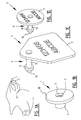
- Figures 1A-1D show an embodiment of the device for an application as ear tag for an animal.
- Figure 1B shows a female ear tag part 1 provided with a passage 2 having a front end 3 and a rear end 4.
- Figure 1C shows a male part 5 of the ear tag which comprises an arrow-shaped element 6 to which is connected a plate-like element 7, on which plate-like element 7 can be arranged identification data.
- Fig. 1D shows a second embodiment of male part 5 which is particularly suitable for pigs.
- Passage 2 of female ear tag part 1 is provided at its front end 3 with three protruding parts 8, 8', 8", as can be seen more clearly in figure 3 . Close to rear end 4 the passage 2 is partly closed off by a closing part 9 which is more clearly visible in figure 4 .
- the tip part 10 of arrow-shaped element 6 is pressed along the front end 3 into passage 2 until the tip part is situated behind protruding parts 8, 8', 8", as seen in the direction from the front end to the rear end of passage 2.
- These protruding parts 8, 8', 8" form stops for the rear side 11 of tip part 10, whereby tip part 10 cannot be taken back out of the passage. If an attempt were made to remove male part 5 from female part 1, the male part 5 would then break at the position of stem 12 of arrow-shaped element 6 and tip part 10 would remain behind in female part 1. Nor furthermore can this tip part 10 be removed along the rear end of passage 2, since this rear end is closed off by closing part 9. In this manner a fraud-proof or so-called "tamper-proof" ear tag is obtained, whereby reuse of either the female part or the male part is made impossible.
- closing part 9 since closing part 9 only partly closes the rear end 4 of the passage, ventilation still remains possible, which is important if tissue parts are entrained during tagging.
- the female part 1 is for instance manufactured from a plastic with a hard, isolating quality such as ASA (acrylonitrile styrene acrylate), PC (polycarbonate) or the like.
- the male ear tag part 5 is generally manufactured from a soft plastic material such as TPU (thermoplastic polyurethane), such that the male ear tag part can be arranged in passage 2 of the female ear tag part 1 without it being necessary to exert much force, and stem 12 of the male ear tag part 5 breaks when the male and female ear tag parts are pulled apart.
- TPU thermoplastic polyurethane
- the diameter of passage 2 is preferably smaller than or equal to the maximum diameter of the arrow-shaped element 6 of male part 5.
- the female part has a substantially disc-shaped body 13, wherein passage 2 is arranged substantially centrally on disc-shaped body 13.
- female part 1 can also be formed without disc body 13 and that many other embodiments are possible.
- this disc body 13 is formed integrally with the rest of female part 1.
- Ear tags are for instance arranged increasingly early on pigs, i.e. already on the day of birth or at 2 to 3 days old, whereby the maximum weight of the ear tag (male and female part together) may not exceed 4 grams according to Dutch standards.
- the maximum weight of the ear tag male and female part together
- Figure 2 shows a number of other possible embodiments of the arrow-shaped element of the male part which can be used for articles other than ear tags. If this is for instance a basket or other product in which an identification device must be fixed, it is in many cases not then essential for the tip part to have a real tip. What is important is that tip part 10' has a maximum diameter which is greater than the diameter of stem 12', such that tip part 10' has rear side 11' against which the protruding parts can engage, this in all positions of the male element in the female element.
- Figure 5A shows a bottom view of female part 1 of figure 3 , in which the three protruding parts 8, 8' and 8" can be clearly seen.
- Figures 5B and 5C show bottom views of two other possible variants.
- the variant of figure 5B has two protruding parts 20, 20', while the variant of figure 5C has four protruding parts 21, 21', 21", 21"'.
- Many other embodiments are thus possible, wherein all that is important is that means are provided which engage behind tip part 10 of arrow-shaped element 6.
- FIG 6A shows a top view of the embodiment of figure 3 .
- This figure clearly shows closing part 9, which is formed from three legs 22, 22', 22" which are connected at one end to the edge of passage 2 and come together at their other end in the centre of passage 2.
- closing part 9 is formed from three legs 22, 22', 22" which are connected at one end to the edge of passage 2 and come together at their other end in the centre of passage 2.
- the three protruding parts 8, 8' and 8" can be seen under legs 22, 22' and 22".
- FIGS. 6B and 6C show two other possible variants.
- the skilled person will understand that many other embodiment variants of closing part 9 are possible, wherein the design must be such that tip part 10 of the arrow-shaped element cannot be removed from the female part along the rear end 4 of passage 2.
- FIG. 7A-7C Provided for this purpose is a mould component 30 which has the size and shape of passage 2 of the female part.
- a mould component 30 which has the size and shape of passage 2 of the female part.
- the mould component 30 also referred to as a forming tip, wherein the protruding parts 31 at the front end of the passage of deformable soft plastic can fold aside so that mould component 30 can be pulled freely out of the ear tag.
- the protruding parts no longer yield and these parts would break off if mould component 30 were removed.
- the technique of figures 7A-7C can thus not be used for a female part of a hard material.
- FIG. 9-11 show further perspective views of the first and second mould components 40, 41.
- the device according to the invention can be provided with an electronic transponder (an RF-tag) which comprises an electronic component and an antenna winding.
- an ear tag such a transponder is generally accommodated in female part 1, this such that it is fully sealed off from the outside environment.
- This transponder must after all be completely isolated against outside influences such as pig bites, sucking on the ear tags, and so on.
- the electronic transponder comprises an electronic component 50 and an antenna winding 51.
- This transponder is placed on a surface of the female part 1 of hard plastic material wherein, in the variant of figure 13 , this surface is a rear side 52 of a disc body.
- the disc-shaped surface is provided with a peripheral edge 53 and an inner edge 54 around passage 2.
- This side 52 is fully sprayed with a hard plastic material.
- the plastic to be sprayed can be the same as that from which the first surface of the female part is made, or another plastic which forms a firm, protective connection to the first formed surface.
- This spraying generally takes place under very high pressure for maximum enclosure of the transponder, since it is a requirement for a stable communication with readers that chip 50 can move as little as possible.
- the transponder Before spraying plastic material around the transponder it should preferably be secured in order to avoid displacement hereof during the spraying. This can take place in different ways, for instance by clamping, glueing or by covering with an optionally self-adhesive foil plate. According to yet another possibility, the transponder can be held by pins during the spraying, which pins can be retracted during the final stage of the spraying. After spraying of side 52 an ear tag part 1 is obtained which has the form of the female ear tag part as shown in figure 1B .
Abstract
Description
- The present invention relates to a device for identifying articles such as animals, comprising a male part and a female part, which male part comprises an arrow-shaped element and which female part is provided with a passage with a front end and a rear end, wherein the arrow-shaped element can be inserted into the passage along the front end and wherein the passage is provided close to the front end with at least one protruding element. The invention further relates to a female part for use in such a device, to a method for manufacturing the female part of such a device, wherein the female part is manufactured by injection moulding using a multipart mould, and to a method for arranging an electronic transponder comprising at least one electronic component and an antenna winding in a part of hard plastic material.
-
EP 0 941 656 discloses a method for arranging a transponder. Devices for identifying animals are for instance described inEP 0 941 656 ,EP 1 161 139 andEP 0 639 942 . In general the existing devices have the drawback of being relatively heavy, since the female part, which must be quite strong, is constructed from a plurality of components. Furthermore, the known embodiments are generally not fully fraud-proof or tamper-proof, wherein tamper-proof is specified in different ear tag regulations as: "the ear tag must display visible signs of any attempt at fraud". -
EP 0 639 942 shows in the figures an ear tag of the type stated in the preamble with a female part with a passage, the rear end of which is wholly open. - The invention has for its object to provide a device and method of the type stated in the preamble, which device has a low weight and is tamper-proof, and which methods are easy to carry out.
- The invention provides for this purpose a device which is distinguished in that the passage is partly closed close to the rear end by a closing part, wherein the partly closed passage, including the protruding element, are manufactured integrally from a hard material. In this manner the arrow-shaped element can be inserted into the passage via the front end of the passage, wherein the at least one protruding element, as seen in the direction from the front end to the rear end of the passage, will engage behind the tip part of the arrow-shaped element and in this manner prevent removal of the arrow-shaped element back along the front end. Because the passage is partly closed near the rear end, it will not be possible either to remove the arrow-shaped element along this rear end, such that a tamper-proof device is obtained which cannot be reused. By manufacturing the passage, including the protruding element, integrally a relatively light device can moreover be obtained.
- The hard material from which the device is manufactured is preferably a hard plastic such as acrylonitrile styrene acrylate (ASA) or polycarbonate (PC). Any other suitable hard material, such as aluminium, does however also lie within the scope of the invention.
- If the device is used as an ear tag for animals, according to a possible embodiment the female part then weighs less than 3 grammes. There are different national regulations wherein a maximum weight for the ear tags is set for different types of animal. By keeping the weight of the female part as low as possible, it is possible to meet these requirements for the different types of animal. For pigs for instance, a maximum weight of only 4 grammes is permitted for piglets for the whole ear tag (male and female part). For cattle this maximum weight is 12 grammes. This is particularly important for animals in which the ear tag is already arranged at a very young age.
- In the case that the device is used as an ear tag for animals, the maximum diameter of the arrow-shaped element is further preferably equal to or greater than the diameter of the passage, such that the ear tag retains an anvil effect during tagging so as to prevent crushing of the ear tissue.
- According to a possible embodiment, the female part is substantially disc-shaped, wherein the passage is arranged substantially centrally on the disc. This is an advantageous design which is particularly suitable for ear tags.
- According to a further feature of the invention, an electronic transponder comprising at least one electronic component and an antenna winding is incorporated in the female part. In this manner a code coupled to the ear tag can be programmed in the electronic component and read in simple manner using an electronic reader. Such an electronic transponder is for instance described in
EP 0 941 656 . - According to the preferred embodiment of the invention, two or more protruding elements are arranged close to the front end, spread regularly along the periphery of the passage. It is further recommended that the perpendicular projections of the protruding parts and of the closing part onto a plane perpendicular to the longitudinal direction of the passage substantially do not overlap each other. As will further be found from the figure description, this has considerable advantages in the performing of the method according to the invention, particularly in respect of the design of the mould components.
- The method according to the invention is distinguished in that
- a first mould component is provided with a size and shape smaller than those of the passage for forming, wherein the cross-section is smaller than or equal to the smallest cross-section of the passage;
- a second mould component is arranged above the first mould component, which component has a lower part which together with the first mould component has substantially the shape and size of the passage, and an upper part which together with the top side of the first mould component bounds a space for the closing part;
- hard material is arranged around these mould components by injection moulding in order to form the passage of the female part;
- the first mould component is removed along the front end of the passage;
- the second mould component is removed along the rear end of the passage.
- As will be elucidated in detail on the basis of the exemplary embodiment of
figures 8A-8C , this method allows a device according to the invention to be made from a hard plastic material, wherein it is particularly possible to integrally manufacture the passage with the protruding parts on one side and the closing part on the other side by injection moulding. - Note that this method is particularly intended for manufacturing a female part from a hard plastic material. For manufacture of a female part from a soft plastic material, such as for instance thermoplastic polyurethane (TPU), it would after all be possible to suffice with one mould component having the shape and size of the passage without a second mould component being necessary. This will be further elucidated with reference to
figures 7A-7C . - According to a preferred embodiment of the method according to the invention, the form and size of the first mould component resembles as closely as possible that of the first passage, but the at least one protruding part and the first mould component, as seen in a projection onto a plane perpendicular to the longitudinal direction of the passage, do not overlap each other. In this way the first mould component can be removed without problem along the front end of the passage.
- It is further recommended that the lower part of the second mould component and the closing part, as seen in the projection onto a plane perpendicular to the longitudinal direction of the passage, do not overlap each other. In this way the second mould component can be removed without problem along the rear end of the passage.
- According to a further developed embodiment, an electronic transponder comprising at least one electronic component and an antenna winding is arranged prior to the injection moulding in a space bounded by the multipart mould, into which space hard material is injected. The electronic transponder is preferably held by mould pins which retract during the injection moulding. In this manner a female part incorporating an electronic transponder can be manufactured in one process from hard plastic material.
- Finally, the present invention relates to a method for arranging an electronic transponder comprising at least one electronic component and an antenna winding in a part of hard plastic material, wherein a plastic material is injected around the transponder in order to form a layer which fully encloses the transponder, wherein this plastic material is chosen such that a firm connection to the hard plastic of the part results. In this way the electronic transponder is completely isolated from outside influences and secured in the female part in completely immobile manner.
- According to a preferred embodiment the transponder is fixed, prior to the injection, against a surface of the part of hard plastic, for instance by clamping, glueing or covering with an optionally self-adhesive foil plate, whereafter the plastic material is injected against this surface.
- The plastic material can be a hard plastic or a soft plastic, such as thermoplastic polyurethane, wherein the only condition is that this plastic material forms a good connection with the hard plastic of the part.
- According to a possible embodiment, the electronic transponder is held by mould pins which retract during the injection moulding of the part of hard plastic, such that the whole part is injected from a hard plastic in one phase.
- According to a possible embodiment of the method which is particularly suitable for an ear tag for animals, the part of hard plastic material has a substantially disc-shaped body which is provided substantially in the centre with a passage for receiving an arrow-shaped element, wherein the transponder is arranged in the disc-shaped body.
- According to a further developed embodiment of this method, a disc-shaped surface with a peripheral edge and an inner edge is provided for the transponder, between which peripheral edge and inner edge the material is injected in order to form the disc-shaped body in which the transponder is incorporated.
- The invention will be further elucidated on the basis of a number of exemplary embodiments of the device and methods according to the invention with reference to the accompanying drawings, in which:
-
Figure 1A shows an embodiment of a device according to the invention fixed to the ear of a pig; -
Figure 1B shows a female part of an embodiment of a device according to the invention; -
Figures 1C and 1D show two possible embodiments of a male part of a device according to the invention; -
Figure 2 shows two other possible embodiments of the arrow-shaped element of the male part of the device according to the invention; -
Figure 3 is a perspective view of the embodiment offigure 1B as seen from the rear end; -
Figure 4 shows the embodiment offigure 3 in section along line IV-IV; -
Figure 5A is a top view of the embodiment offigure 4 ; -
Figures 5B and 5C show top views of two other possible variants of the female part of the device according to the invention; -
Figure 6A is a bottom view of the embodiment offigure 4 ; -
Figures 6B and 6C are bottom views of two other possible variants of the female part of a device according to the invention; -
Figures 7A-7C illustrate the method for manufacturing a cavity in a female part from soft material, as according to the prior art; -
Figures 8A-8C illustrate an embodiment of the method for manufacturing a cavity in a female part of a device according to the invention; -
Figures 9 and 10 show perspective views of an embodiment of the second mould component for use in the method according to the invention; -
Figure 11 shows a perspective view of an embodiment of the first mould component for use in the method according to the invention; -
Figure 12 shows a cross-section through the first mould component close to the front end of the passage of the embodiment offigure 3 ; and -
Figure 13 shows a perspective view of a part of hard plastic material with a surface against which a transponder is fixed. - The embodiments of the device according to the invention illustrated in the figures are specifically intended as ear tag for animals, more particularly small and large ruminants, pigs and other utility animals, but the skilled person will understand that analogous devices can be used just as well to identify other types of article.
-
Figures 1A-1D show an embodiment of the device for an application as ear tag for an animal. -
Figure 1B shows a female ear tag part 1 provided with apassage 2 having afront end 3 and arear end 4.Figure 1C shows amale part 5 of the ear tag which comprises an arrow-shapedelement 6 to which is connected a plate-like element 7, on which plate-like element 7 can be arranged identification data. -
Fig. 1D shows a second embodiment ofmale part 5 which is particularly suitable for pigs. -
Passage 2 of female ear tag part 1 is provided at itsfront end 3 with three protrudingparts figure 3 . Close torear end 4 thepassage 2 is partly closed off by aclosing part 9 which is more clearly visible infigure 4 . - For fixing of the ear tag to the ear of an animal, the
tip part 10 of arrow-shapedelement 6 is pressed along thefront end 3 intopassage 2 until the tip part is situated behind protrudingparts passage 2. These protrudingparts rear side 11 oftip part 10, wherebytip part 10 cannot be taken back out of the passage. If an attempt were made to removemale part 5 from female part 1, themale part 5 would then break at the position ofstem 12 of arrow-shapedelement 6 and tippart 10 would remain behind in female part 1. Nor furthermore can thistip part 10 be removed along the rear end ofpassage 2, since this rear end is closed off by closingpart 9. In this manner a fraud-proof or so-called "tamper-proof" ear tag is obtained, whereby reuse of either the female part or the male part is made impossible. - Further note that, since closing
part 9 only partly closes therear end 4 of the passage, ventilation still remains possible, which is important if tissue parts are entrained during tagging. - The female part 1 is for instance manufactured from a plastic with a hard, isolating quality such as ASA (acrylonitrile styrene acrylate), PC (polycarbonate) or the like. The male
ear tag part 5 is generally manufactured from a soft plastic material such as TPU (thermoplastic polyurethane), such that the male ear tag part can be arranged inpassage 2 of the female ear tag part 1 without it being necessary to exert much force, and stem 12 of the maleear tag part 5 breaks when the male and female ear tag parts are pulled apart. - So that the ear tag retains an anvil effect after tagging in order to avoid crushing of the ear tissue, the diameter of
passage 2 is preferably smaller than or equal to the maximum diameter of the arrow-shapedelement 6 ofmale part 5. - In the shown embodiment the female part has a substantially disc-shaped
body 13, whereinpassage 2 is arranged substantially centrally on disc-shapedbody 13. The skilled person will however understand that female part 1 can also be formed withoutdisc body 13 and that many other embodiments are possible. In the shown example thisdisc body 13 is formed integrally with the rest of female part 1. - It is of further importance to limit the weight of ear tags as much as possible. Ear tags are for instance arranged increasingly early on pigs, i.e. already on the day of birth or at 2 to 3 days old, whereby the maximum weight of the ear tag (male and female part together) may not exceed 4 grams according to Dutch standards. In the case of calves it is also obligatory in many countries to tag within 3 days of birth. It is thus a prerequisite that the female ear tag part is thin-walled and uses a minimum of plastic components. Because the shown embodiment of the female part is manufactured integrally from a hard plastic material, and not from two, three or more hard plastic components as in the prior art devices, such low weights can be achieved.
-
Figure 2 shows a number of other possible embodiments of the arrow-shaped element of the male part which can be used for articles other than ear tags. If this is for instance a basket or other product in which an identification device must be fixed, it is in many cases not then essential for the tip part to have a real tip. What is important is that tip part 10' has a maximum diameter which is greater than the diameter of stem 12', such that tip part 10' has rear side 11' against which the protruding parts can engage, this in all positions of the male element in the female element. -
Figure 5A shows a bottom view of female part 1 offigure 3 , in which the three protrudingparts Figures 5B and 5C show bottom views of two other possible variants. The variant offigure 5B has two protrudingparts 20, 20', while the variant offigure 5C has four protrudingparts tip part 10 of arrow-shapedelement 6. -
Figure 6A shows a top view of the embodiment offigure 3 . This figure clearly shows closingpart 9, which is formed from threelegs passage 2 and come together at their other end in the centre ofpassage 2. In the top view the three protrudingparts legs -
Figures 6B and 6C show two other possible variants. The skilled person will understand that many other embodiment variants of closingpart 9 are possible, wherein the design must be such thattip part 10 of the arrow-shaped element cannot be removed from the female part along therear end 4 ofpassage 2. - Further note that in the embodiment of
figures 1-4 the perpendicular projection onto a plane perpendicular to the longitudinal direction ofpassage 2 of the three protrudingparts part 9 do not overlap each other. This has the advantage that the method for manufacturing the ear tag can be performed with simplified mould components, as will be further shown in the description offigures 8-11 . - If it is desired to manufacture female part 1 from a soft plastic material, this can take place according to the prior art in a simple manner as illustrated in
figures 7A-7C . Provided for this purpose is amould component 30 which has the size and shape ofpassage 2 of the female part. After injection moulding of the female ear tag part 1 it is easy to remove themould component 30, also referred to as a forming tip, wherein the protrudingparts 31 at the front end of the passage of deformable soft plastic can fold aside so thatmould component 30 can be pulled freely out of the ear tag. With the use of a hard material the protruding parts no longer yield and these parts would break off ifmould component 30 were removed. The technique offigures 7A-7C can thus not be used for a female part of a hard material. - An embodiment of the method of the invention will now be illustrated with reference to
figures 8A-8C . This method makes use of twomould components mould component 30 offigures 7A-7C : - a
first mould component 40 is provided with a size and shape smaller than those of thepassage 2 to be formed, wherein the maximum cross-section S (see the hatched area infigure 12 ) is here equal to the smallest cross-section ofpassage 2, i.e. the cross-section ofpassage 2 at the position of protrudingparts - above the
first mould component 40 is arranged asecond mould component 41 having alower part 42 which, together withfirst mould component 40, has substantially the form and the size ofpassage 2, and having anupper part 43 which, together with theupper side 44 offirst mould component 40, bounds a space for closingpart 9; - after hard material has been arranged around these
mould components figures 8A-8C the first mould component can be removed along thefront end 3 ofpassage 2 and thesecond mould component 41 can be removed along therear end 4 ofpassage 2. - Additional mould components are of course also necessary to form the
disc body 13 of female part 1, but these are deemed known and will not be further elucidated here.Figures 9-11 show further perspective views of the first andsecond mould components - Finally, the device according to the invention can be provided with an electronic transponder (an RF-tag) which comprises an electronic component and an antenna winding. In the case of an ear tag such a transponder is generally accommodated in female part 1, this such that it is fully sealed off from the outside environment. This transponder must after all be completely isolated against outside influences such as pig bites, sucking on the ear tags, and so on.
- An embodiment of the method for arranging an electronic transponder in a female part of an ear tag will now be described with reference to
figure 13 . The electronic transponder comprises anelectronic component 50 and an antenna winding 51. This transponder is placed on a surface of the female part 1 of hard plastic material wherein, in the variant offigure 13 , this surface is arear side 52 of a disc body. In the shown example the disc-shaped surface is provided with aperipheral edge 53 and aninner edge 54 aroundpassage 2. Thisside 52 is fully sprayed with a hard plastic material. The plastic to be sprayed can be the same as that from which the first surface of the female part is made, or another plastic which forms a firm, protective connection to the first formed surface. This spraying generally takes place under very high pressure for maximum enclosure of the transponder, since it is a requirement for a stable communication with readers thatchip 50 can move as little as possible. - Before spraying plastic material around the transponder it should preferably be secured in order to avoid displacement hereof during the spraying. This can take place in different ways, for instance by clamping, glueing or by covering with an optionally self-adhesive foil plate. According to yet another possibility, the transponder can be held by pins during the spraying, which pins can be retracted during the final stage of the spraying. After spraying of
side 52 an ear tag part 1 is obtained which has the form of the female ear tag part as shown infigure 1B . - The invention is not limited to the embodiment variants described above on the basis of the figures, and the skilled person will appreciate that many modifications are possible without departing from the scope of the invention, this scope being defined solely by the appended claims.
Claims (24)
- Method for arranging an electronic transponder comprising at least one electronic component and an antenna winding in a part of hard plastic material which is manufactured by injection moulding, characterized in that a plastic material is injected around the transponder in order to form a layer which fully encloses the transponder, wherein this plastic material is chosen such that a firm connection to the hard plastic of the part results.
- Method as claimed in claim 1, characterized in that the transponder is fixed, prior to the injection, against a surface of the part of hard plastic, whereafter the plastic material is injected against this surface.
- Method as claimed in claim 2, characterized in that the plastic material is also a hard plastic.
- Method as claimed in claim 2, characterized in that the plastic material is a soft plastic, such as thermoplastic polyurethane.
- Method as claimed in claim 1, characterized in that the electronic transponder is held by mould pins which retract during the injection moulding of the part of hard plastic, such that the part is injected from a hard plastic in one phase.
- Method as claimed in any of the claims 1-5, characterized in that the part of a harder plastic has a substantially disc-shaped body which is provided substantially in the centre with a passage for receiving an arrow-shaped element, wherein the transponder is arranged in the disc-shaped body.
- Method as claimed in claim 6, characterized in that the surface for the transponder is disc-shaped and provided with a peripheral edge and inner edge, between which peripheral edge and inner edge the plastic material is injected.
- Device comprising an electronic transponder comprising at least one electronic component (50) and an antenna winding (51), fabricated according to the method of any of the claims 1-7.
- Device preferably as claimed in claim 8 for identifying articles such as animals, comprising a male part (5) and a female part (1), which male part comprises an arrow-shaped element (6) and which female part is provided with a passage (2) with a front end (3) and a rear end (4), wherein the arrow-shaped element (6) can be inserted into the passage along the front end, wherein the passage is provided close to the front end with at least one protruding element (8, 8', 8"), characterized in that the passage is partly closed close to the rear end by a closing part (9), wherein the partly closed passage, including the protruding element, are manufactured integrally from a hard material.
- Device as claimed in claim 9, characterized in that the hard material is a hard plastic.
- Device as claimed in claim 10, characterized in that the hard plastic is acrylonitrile styrene acrylate (ASA) or polycarbonate (PC).
- Device as claimed in any of the claims 9-11, characterized in that the female part weighs less than 3 g.
- Device as claimed in any of the claims 9-12, characterized in that the maximum diameter of the arrow-shaped element is equal to or greater than the diameter of the passage.
- Device as claimed in any of the claims 9-13, characterized in that the female part has a substantially disc-shaped body (13), wherein the passage is arranged substantially centrally on the disc-shaped body.
- Device as claimed in any of the claims 9-14, characterized in that an electronic transponder comprising at least one electronic component (50) and an antenna winding (51) is incorporated in the female part.
- Device as claimed in any of the claims 9-15, characterized in that two or more protruding elements are arranged at the front end, spread regularly along the periphery of the passage.
- Device as claimed in any of the claims 9-16, characterized in that the perpendicular projections of the protruding parts and of the closing part onto a plane perpendicular to the longitudinal direction of the passage substantially do not overlap each other.
- Female part for use in a device as claimed in any of the claims 9-17.
- Method for manufacturing the female part of a device as claimed in any of the claims 9-18, wherein the female part is manufactured by injection moulding using a multipart mould, characterized in that- a first mould component (40) is provided with a size and shape smaller than those of the passage for forming, wherein the cross-section S is smaller than or equal to the smallest cross-section of the passage;- a second mould component (41) is arranged above the first mould component, which second component has a lower part (42) which, together with the first mould component, has substantially the shape and size of the passage, and an upper part (43) which, together with the top side (44) of the first mould component, bounds a space for the closing part;- hard material is arranged around these mould components by injection moulding in order to form the passage of the female part;- the first mould component is removed along the front end of the passage;- the second mould component is removed along the rear end of the passage.
- Method as claimed in claim 19, characterized in that the first mould component resembles as closely as possible the form of the passage, but wherein the at least one protruding part and the first mould component, as seen in a projection onto a plane perpendicular to the longitudinal direction of the passage, do not overlap each other.
- Method as claimed in claim 19 or 20, characterized in that the lower part of the second mould component and the closing part, as seen in a projection onto a plane perpendicular to the longitudinal direction of the passage, do not overlap each other.
- Method as claimed in any of the claims 19-21, characterized in that an electronic transponder comprising at least one electronic component and an antenna winding is arranged prior to the injection moulding in a space which is bounded by the multipart mould and into which hard material is subsequently arranged by injection moulding.
- Method as claimed in claim 22, characterized in that the electronic transponder is held by mould pins which retract during the injection moulding.
- Method as claimed in claim 22 or 23 for manufacturing a female part of a device as claimed in claim 14, characterized in that the electronic transponder is arranged prior to injection moulding in a cavity for the disc-shaped body formed by mould components.
Priority Applications (1)
| Application Number | Priority Date | Filing Date | Title |
|---|---|---|---|
| PL08101456T PL1913812T3 (en) | 2004-10-25 | 2005-10-20 | Identification device and method for manufacturing thereof |
Applications Claiming Priority (2)
| Application Number | Priority Date | Filing Date | Title |
|---|---|---|---|
| BE200400518A BE1016247A5 (en) | 2004-10-25 | 2004-10-25 | IDENTIFICATION DEVICE AND METHOD FOR MANUFACTURING IT |
| EP20050808410 EP1809096B1 (en) | 2004-10-25 | 2005-10-20 | Identification device and method for manufacturing thereof |
Related Parent Applications (2)
| Application Number | Title | Priority Date | Filing Date |
|---|---|---|---|
| EP05808410.4 Division | 2005-10-20 | ||
| EP20050808410 Division EP1809096B1 (en) | 2004-10-25 | 2005-10-20 | Identification device and method for manufacturing thereof |
Publications (3)
| Publication Number | Publication Date |
|---|---|
| EP1913812A2 true EP1913812A2 (en) | 2008-04-23 |
| EP1913812A3 EP1913812A3 (en) | 2008-09-17 |
| EP1913812B1 EP1913812B1 (en) | 2010-05-05 |
Family
ID=34974209
Family Applications (2)
| Application Number | Title | Priority Date | Filing Date |
|---|---|---|---|
| EP20080101456 Not-in-force EP1913812B1 (en) | 2004-10-25 | 2005-10-20 | Identification device and method for manufacturing thereof |
| EP20050808410 Not-in-force EP1809096B1 (en) | 2004-10-25 | 2005-10-20 | Identification device and method for manufacturing thereof |
Family Applications After (1)
| Application Number | Title | Priority Date | Filing Date |
|---|---|---|---|
| EP20050808410 Not-in-force EP1809096B1 (en) | 2004-10-25 | 2005-10-20 | Identification device and method for manufacturing thereof |
Country Status (16)
| Country | Link |
|---|---|
| US (3) | US8099884B2 (en) |
| EP (2) | EP1913812B1 (en) |
| CN (2) | CN101072499B (en) |
| AT (2) | ATE423460T1 (en) |
| AU (2) | AU2005299263B2 (en) |
| BE (1) | BE1016247A5 (en) |
| BR (1) | BRPI0517453B1 (en) |
| CA (1) | CA2587012C (en) |
| DE (2) | DE602005021167D1 (en) |
| DK (2) | DK1809096T3 (en) |
| ES (2) | ES2321428T3 (en) |
| IN (1) | IN2014CN00972A (en) |
| MX (1) | MX2007004865A (en) |
| NZ (2) | NZ554909A (en) |
| PL (2) | PL1913812T3 (en) |
| WO (1) | WO2006045162A2 (en) |
Families Citing this family (22)
| Publication number | Priority date | Publication date | Assignee | Title |
|---|---|---|---|---|
| WO2009089580A1 (en) * | 2008-01-14 | 2009-07-23 | Drover's Ay-One Pty. Ltd. | Rfid device and method of manufacture thereof |
| EP2384618B1 (en) * | 2010-04-14 | 2024-02-14 | Reinhard Nehls | System for marking a non-human biological object and removing a sample |
| FR2961087B1 (en) | 2010-06-09 | 2013-06-28 | Allflex Europ | TOOL FOR SAMPLING AN ANIMAL TISSUE SAMPLE. |
| FR2963203B1 (en) | 2010-07-30 | 2013-11-15 | Allflex Europ | MARKING AND / OR ANIMAL TISSUE COLLECTION ASSEMBLY AND CORRESPONDING MARKING AND / OR LEANING TOOL. |
| FR2963722B1 (en) * | 2010-08-13 | 2012-08-10 | Allflex Europ | ANIMAL IDENTIFICATION RESIN DEVICE AND METHOD FOR MANUFACTURING THE SAME |
| NL1038416C2 (en) | 2010-12-01 | 2012-06-04 | Ique Rfid Technologies B V | RFID TRANSPONDER. |
| CA2779880C (en) | 2010-12-03 | 2013-06-25 | Pluritag Inc. | Auricular livestock identification tag |
| AU2013296147B2 (en) * | 2012-07-26 | 2018-03-01 | Enduro Tags Pty Ltd | Improved animal tag |
| US20160116380A1 (en) | 2013-06-05 | 2016-04-28 | Snpshot Trustee Limited | Tissue sampler |
| RU2680186C2 (en) | 2013-10-18 | 2019-02-18 | Снпшот Трасти Лимитед | Biopsy sampler and sample collector |
| AT13811U1 (en) * | 2014-01-16 | 2014-09-15 | Sapro Kunststoffverarbeitung Und Laserbeschriftungen E U | Ear tag for identification and identification of animals |
| AR100080A1 (en) * | 2014-04-15 | 2016-09-07 | Allflex Europe Sas | BRAND FOR THE IDENTIFICATION OF ANIMALS |
| USD753479S1 (en) * | 2014-11-21 | 2016-04-12 | Alex Shlaferman | Clamshell package |
| US20180249679A1 (en) * | 2015-09-13 | 2018-09-06 | Katrina Goff Candy | Animal recognition and location device |
| FR3054408B1 (en) | 2016-07-27 | 2019-07-12 | Allflex Europe | FEMALE PART OF ANIMAL IDENTIFICATION DEVICE COMPRISING A BLOCKING MEMBER OF THE MALE PART IN THE FEMALE PART |
| US9936676B1 (en) * | 2017-08-07 | 2018-04-10 | Arrow Tag, LLC | Animal identification tag |
| US10058073B1 (en) | 2017-08-07 | 2018-08-28 | Arrow Tag, LLC | Animal tag attachment tool |
| USD853664S1 (en) * | 2017-08-30 | 2019-07-09 | Craig E. Ritchey | Ear tag component |
| USD947468S1 (en) | 2018-05-23 | 2022-03-29 | Craig E. Ritchey | Ear tag component |
| US11235500B2 (en) | 2018-08-03 | 2022-02-01 | Y-Tex Corporation | System and method for molding RFID tags |
| DE102019130175A1 (en) * | 2019-11-08 | 2021-05-12 | Hellermanntyton Gmbh | Injection molding of a component, such as a cable holder, with an integrated wireless identification film |
| US20220408691A1 (en) * | 2019-12-19 | 2022-12-29 | Allflex USA LLC | Vaccination Identification Button For Electronic Identification Button Tags To Identify Cattle As Being Inoculated Against Brucellosis, and Kits and Methods Related Thereto |
Citations (3)
| Publication number | Priority date | Publication date | Assignee | Title |
|---|---|---|---|---|
| EP0639942A1 (en) | 1992-05-13 | 1995-03-01 | Allflex New Zealand Limited | A carrier for an electronic identification device |
| EP0941656A1 (en) | 1998-03-09 | 1999-09-15 | N.V. Nederlandsche Apparatenfabriek NEDAP | Carrier provided with an electronic transponder for identifying animals, and method for producing such carrier |
| EP1161139A1 (en) | 1999-02-18 | 2001-12-12 | Gardner, Michael Stuart | Animal tag |
Family Cites Families (29)
| Publication number | Priority date | Publication date | Assignee | Title |
|---|---|---|---|---|
| US3388492A (en) * | 1966-07-12 | 1968-06-18 | Dana Co C H | Animal ear tag |
| US3731414A (en) * | 1971-02-05 | 1973-05-08 | B Murphy | Animal ear tags and applicators therefor |
| US4920671A (en) * | 1985-02-22 | 1990-05-01 | Y-Tex Corporation | Male component for two-piece animal ear tag |
| CN1014388B (en) * | 1985-09-26 | 1991-10-23 | 法国新罗卡尔有限公司 | Ear tag for marking animals |
| FR2635437B1 (en) * | 1988-08-19 | 1992-06-05 | Biwi Sa | IDENTIFICATION MARK FOR GAME OR LIVESTOCK |
| US5166502A (en) * | 1990-01-05 | 1992-11-24 | Trend Plastics, Inc. | Gaming chip with implanted programmable identifier means and process for fabricating same |
| US5768813A (en) * | 1992-05-13 | 1998-06-23 | Reboul; Jerome | Carrier for an electronic identification device |
| US5411688A (en) * | 1992-06-29 | 1995-05-02 | Duotec Products Associates | Method for forming plastic molded panels with inserts |
| CN1126542A (en) * | 1993-11-15 | 1996-07-17 | 阿福来斯新西兰有限公司 | A carrier for an electronic identification device |
| JP3337847B2 (en) * | 1995-02-27 | 2002-10-28 | 株式会社東芝 | Manufacturing method of electronic component built-in card |
| AUPO032296A0 (en) * | 1996-06-06 | 1996-07-04 | Finlayson, Dorothy Elizabeth | Ear tag |
| FR2768836B1 (en) * | 1997-06-11 | 2000-06-16 | Reydet Finance | IDENTIFICATION DEVICE AND METHOD FOR MANUFACTURING THE ASSOCIATED DEVICE |
| BE1012433A3 (en) * | 1997-06-30 | 2000-11-07 | Splitthoff Josef | Identification label for animals. |
| EP0913791A1 (en) * | 1997-10-30 | 1999-05-06 | Navitas Co., Limited | Method for manufacturing card product and manufacturing apparatus therefor |
| NO975015L (en) * | 1997-10-31 | 1999-02-15 | Os Husdyrmerkefabrikk As | Livestock tag locking system |
| US6666170B1 (en) * | 1997-12-09 | 2003-12-23 | Allflex New Zealand Limited | Animal ear tag |
| DE29812383U1 (en) * | 1998-07-11 | 1998-10-22 | Ruppert Helmut Dipl Ing | Ear tag with an electronic identification device |
| WO2000007834A2 (en) * | 1998-08-03 | 2000-02-17 | The Goodyear Tire & Rubber Company | Mounting transponders in pneumatic tires |
| US6323771B1 (en) * | 1999-04-09 | 2001-11-27 | James S. Payne | Method of identifying animals via universal identification scheme |
| US6296190B1 (en) * | 1999-05-03 | 2001-10-02 | Trend Plastics, Inc. | Gaming chip with transponder and a method for making same |
| EP1052595B1 (en) * | 1999-05-14 | 2001-09-19 | Sokymat Sa | Transponder and injection-moulded object and method for manufacturing the same |
| US6441741B1 (en) * | 1999-05-17 | 2002-08-27 | Avid Identification Systems, Inc. | Overmolded transponder |
| US6513271B2 (en) * | 2001-04-11 | 2003-02-04 | Verilogik, Inc. | Tamper-proof animal identification tag |
| US20070060304A1 (en) * | 2001-11-24 | 2007-03-15 | Jeon Ran S | Casino chip with antitheft and antiforgery tag circuit and manufacturing method thereof |
| GB2392138B (en) * | 2002-08-23 | 2004-10-13 | Shearwell Data Ltd | Animal identifiers |
| AU2002952186A0 (en) * | 2002-10-22 | 2002-10-31 | Edney, Neil Frederick | Tagging animals |
| ATE445320T1 (en) * | 2004-08-27 | 2009-10-15 | Nehls Reinhard | EARTAG ELEMENT AND METHOD FOR PRODUCING AN EARTAG ELEMENT |
| US7607249B2 (en) * | 2005-07-15 | 2009-10-27 | Innovatier Inc. | RFID bracelet and method for manufacturing a RFID bracelet |
| WO2009089580A1 (en) * | 2008-01-14 | 2009-07-23 | Drover's Ay-One Pty. Ltd. | Rfid device and method of manufacture thereof |
-
2004
- 2004-10-25 BE BE200400518A patent/BE1016247A5/en not_active IP Right Cessation
-
2005
- 2005-10-20 US US11/664,954 patent/US8099884B2/en not_active Expired - Fee Related
- 2005-10-20 ES ES05808410T patent/ES2321428T3/en active Active
- 2005-10-20 AU AU2005299263A patent/AU2005299263B2/en active Active
- 2005-10-20 ES ES08101456T patent/ES2345797T3/en active Active
- 2005-10-20 CA CA 2587012 patent/CA2587012C/en not_active Expired - Fee Related
- 2005-10-20 NZ NZ554909A patent/NZ554909A/en not_active IP Right Cessation
- 2005-10-20 DE DE200560021167 patent/DE602005021167D1/en active Active
- 2005-10-20 CN CN2005800365211A patent/CN101072499B/en not_active Expired - Fee Related
- 2005-10-20 NZ NZ587936A patent/NZ587936A/en not_active IP Right Cessation
- 2005-10-20 BR BRPI0517453-8A patent/BRPI0517453B1/en not_active IP Right Cessation
- 2005-10-20 DK DK05808410T patent/DK1809096T3/en active
- 2005-10-20 AT AT05808410T patent/ATE423460T1/en active
- 2005-10-20 WO PCT/BE2005/000148 patent/WO2006045162A2/en active Application Filing
- 2005-10-20 DK DK08101456T patent/DK1913812T3/en active
- 2005-10-20 IN IN972CHN2014 patent/IN2014CN00972A/en unknown
- 2005-10-20 EP EP20080101456 patent/EP1913812B1/en not_active Not-in-force
- 2005-10-20 CN CN201110117934XA patent/CN102273412B/en not_active Expired - Fee Related
- 2005-10-20 EP EP20050808410 patent/EP1809096B1/en not_active Not-in-force
- 2005-10-20 MX MX2007004865A patent/MX2007004865A/en active IP Right Grant
- 2005-10-20 PL PL08101456T patent/PL1913812T3/en unknown
- 2005-10-20 AT AT08101456T patent/ATE466478T1/en active
- 2005-10-20 PL PL05808410T patent/PL1809096T3/en unknown
- 2005-10-20 DE DE200560012982 patent/DE602005012982D1/en active Active
-
2010
- 2010-11-19 AU AU2010246334A patent/AU2010246334B2/en not_active Ceased
-
2011
- 2011-01-07 US US12/986,910 patent/US9005505B2/en not_active Expired - Fee Related
- 2011-10-11 US US13/270,839 patent/US20120118978A1/en not_active Abandoned
Patent Citations (3)
| Publication number | Priority date | Publication date | Assignee | Title |
|---|---|---|---|---|
| EP0639942A1 (en) | 1992-05-13 | 1995-03-01 | Allflex New Zealand Limited | A carrier for an electronic identification device |
| EP0941656A1 (en) | 1998-03-09 | 1999-09-15 | N.V. Nederlandsche Apparatenfabriek NEDAP | Carrier provided with an electronic transponder for identifying animals, and method for producing such carrier |
| EP1161139A1 (en) | 1999-02-18 | 2001-12-12 | Gardner, Michael Stuart | Animal tag |
Also Published As
Similar Documents
| Publication | Publication Date | Title |
|---|---|---|
| EP1913812B1 (en) | Identification device and method for manufacturing thereof | |
| ES2390538T3 (en) | Animal identification card and recycling procedure for said card | |
| AU2014386957B2 (en) | Metal ear tag with overmoulded cover for transponder housing, and method of assembling the same | |
| EP2534945A1 (en) | Flexible electronic ear tag | |
| JP2005224214A (en) | Animal ear tag | |
| AU2006334756B2 (en) | Ear tag for identifying animals | |
| KR100687082B1 (en) | History tag for swine using Radio frequency identification chip | |
| AU2012258300A1 (en) | Animal identification device | |
| US20100199531A1 (en) | Visual tag | |
| JP2018033398A (en) | Identification tag | |
| CN107006386B (en) | Electronic ear tag and ear tag pliers | |
| KR101580767B1 (en) | Earmark for animal | |
| CN214853568U (en) | Novel UHF label structure and animal ear tag | |
| AU2004233502A1 (en) | Improvements in animal identification tags | |
| KR20110083035A (en) | Earmark for preventing forgery | |
| JP2018196339A (en) | Individual identification tag | |
| KR20100004314U (en) | Animal registration card concerned animal identification tag insert RFID tag | |
| JP2000209975A (en) | Earmark for animal |
Legal Events
| Date | Code | Title | Description |
|---|---|---|---|
| PUAI | Public reference made under article 153(3) epc to a published international application that has entered the european phase |
Free format text: ORIGINAL CODE: 0009012 |
|
| 17P | Request for examination filed |
Effective date: 20080211 |
|
| AC | Divisional application: reference to earlier application |
Ref document number: 1809096 Country of ref document: EP Kind code of ref document: P |
|
| AK | Designated contracting states |
Kind code of ref document: A2 Designated state(s): AT BE BG CH CY CZ DE DK EE ES FI FR GB GR HU IE IS IT LI LT LU LV MC NL PL PT RO SE SI SK TR |
|
| RAP1 | Party data changed (applicant data changed or rights of an application transferred) |
Owner name: ALLFLEX EUROPE SAS |
|
| PUAL | Search report despatched |
Free format text: ORIGINAL CODE: 0009013 |
|
| AK | Designated contracting states |
Kind code of ref document: A3 Designated state(s): AT BE BG CH CY CZ DE DK EE ES FI FR GB GR HU IE IS IT LI LT LU LV MC NL PL PT RO SE SI SK TR |
|
| 17Q | First examination report despatched |
Effective date: 20090218 |
|
| AKX | Designation fees paid |
Designated state(s): AT BE BG CH CY CZ DE DK EE ES FI FR GB GR HU IE IS IT LI LT LU LV MC NL PL PT RO SE SI SK TR |
|
| GRAP | Despatch of communication of intention to grant a patent |
Free format text: ORIGINAL CODE: EPIDOSNIGR1 |
|
| GRAS | Grant fee paid |
Free format text: ORIGINAL CODE: EPIDOSNIGR3 |
|
| GRAA | (expected) grant |
Free format text: ORIGINAL CODE: 0009210 |
|
| AC | Divisional application: reference to earlier application |
Ref document number: 1809096 Country of ref document: EP Kind code of ref document: P |
|
| AK | Designated contracting states |
Kind code of ref document: B1 Designated state(s): AT BE BG CH CY CZ DE DK EE ES FI FR GB GR HU IE IS IT LI LT LU LV MC NL PL PT RO SE SI SK TR |
|
| REG | Reference to a national code |
Ref country code: GB Ref legal event code: FG4D |
|
| REG | Reference to a national code |
Ref country code: CH Ref legal event code: NV Representative=s name: ARNOLD & SIEDSMA AG Ref country code: CH Ref legal event code: EP |
|
| REG | Reference to a national code |
Ref country code: IE Ref legal event code: FG4D |
|
| REG | Reference to a national code |
Ref country code: GR Ref legal event code: EP Ref document number: 20100401126 Country of ref document: GR |
|
| REF | Corresponds to: |
Ref document number: 602005021167 Country of ref document: DE Date of ref document: 20100617 Kind code of ref document: P |
|
| REG | Reference to a national code |
Ref country code: SE Ref legal event code: TRGR |
|
| REG | Reference to a national code |
Ref country code: NL Ref legal event code: T3 |
|
| REG | Reference to a national code |
Ref country code: DK Ref legal event code: T3 |
|
| REG | Reference to a national code |
Ref country code: ES Ref legal event code: FG2A Ref document number: 2345797 Country of ref document: ES Kind code of ref document: T3 |
|
| LTIE | Lt: invalidation of european patent or patent extension |
Effective date: 20100505 |
|
| PG25 | Lapsed in a contracting state [announced via postgrant information from national office to epo] |
Ref country code: LT Free format text: LAPSE BECAUSE OF FAILURE TO SUBMIT A TRANSLATION OF THE DESCRIPTION OR TO PAY THE FEE WITHIN THE PRESCRIBED TIME-LIMIT Effective date: 20100505 |
|
| REG | Reference to a national code |
Ref country code: PL Ref legal event code: T3 |
|
| PG25 | Lapsed in a contracting state [announced via postgrant information from national office to epo] |
Ref country code: SI Free format text: LAPSE BECAUSE OF FAILURE TO SUBMIT A TRANSLATION OF THE DESCRIPTION OR TO PAY THE FEE WITHIN THE PRESCRIBED TIME-LIMIT Effective date: 20100505 Ref country code: LV Free format text: LAPSE BECAUSE OF FAILURE TO SUBMIT A TRANSLATION OF THE DESCRIPTION OR TO PAY THE FEE WITHIN THE PRESCRIBED TIME-LIMIT Effective date: 20100505 Ref country code: IS Free format text: LAPSE BECAUSE OF FAILURE TO SUBMIT A TRANSLATION OF THE DESCRIPTION OR TO PAY THE FEE WITHIN THE PRESCRIBED TIME-LIMIT Effective date: 20100905 Ref country code: FI Free format text: LAPSE BECAUSE OF FAILURE TO SUBMIT A TRANSLATION OF THE DESCRIPTION OR TO PAY THE FEE WITHIN THE PRESCRIBED TIME-LIMIT Effective date: 20100505 |
|
| PG25 | Lapsed in a contracting state [announced via postgrant information from national office to epo] |
Ref country code: CY Free format text: LAPSE BECAUSE OF FAILURE TO SUBMIT A TRANSLATION OF THE DESCRIPTION OR TO PAY THE FEE WITHIN THE PRESCRIBED TIME-LIMIT Effective date: 20100526 |
|
| PG25 | Lapsed in a contracting state [announced via postgrant information from national office to epo] |
Ref country code: PT Free format text: LAPSE BECAUSE OF FAILURE TO SUBMIT A TRANSLATION OF THE DESCRIPTION OR TO PAY THE FEE WITHIN THE PRESCRIBED TIME-LIMIT Effective date: 20100906 Ref country code: EE Free format text: LAPSE BECAUSE OF FAILURE TO SUBMIT A TRANSLATION OF THE DESCRIPTION OR TO PAY THE FEE WITHIN THE PRESCRIBED TIME-LIMIT Effective date: 20100505 |
|
| PG25 | Lapsed in a contracting state [announced via postgrant information from national office to epo] |
Ref country code: CZ Free format text: LAPSE BECAUSE OF FAILURE TO SUBMIT A TRANSLATION OF THE DESCRIPTION OR TO PAY THE FEE WITHIN THE PRESCRIBED TIME-LIMIT Effective date: 20100505 Ref country code: RO Free format text: LAPSE BECAUSE OF FAILURE TO SUBMIT A TRANSLATION OF THE DESCRIPTION OR TO PAY THE FEE WITHIN THE PRESCRIBED TIME-LIMIT Effective date: 20100505 Ref country code: SK Free format text: LAPSE BECAUSE OF FAILURE TO SUBMIT A TRANSLATION OF THE DESCRIPTION OR TO PAY THE FEE WITHIN THE PRESCRIBED TIME-LIMIT Effective date: 20100505 |
|
| PLBE | No opposition filed within time limit |
Free format text: ORIGINAL CODE: 0009261 |
|
| STAA | Information on the status of an ep patent application or granted ep patent |
Free format text: STATUS: NO OPPOSITION FILED WITHIN TIME LIMIT |
|
| 26N | No opposition filed |
Effective date: 20110208 |
|
| REG | Reference to a national code |
Ref country code: DE Ref legal event code: R097 Ref document number: 602005021167 Country of ref document: DE Effective date: 20110207 |
|
| PG25 | Lapsed in a contracting state [announced via postgrant information from national office to epo] |
Ref country code: MC Free format text: LAPSE BECAUSE OF NON-PAYMENT OF DUE FEES Effective date: 20101031 |
|
| GBPC | Gb: european patent ceased through non-payment of renewal fee |
Effective date: 20101020 |
|
| PG25 | Lapsed in a contracting state [announced via postgrant information from national office to epo] |
Ref country code: GB Free format text: LAPSE BECAUSE OF NON-PAYMENT OF DUE FEES Effective date: 20101020 |
|
| PG25 | Lapsed in a contracting state [announced via postgrant information from national office to epo] |
Ref country code: LU Free format text: LAPSE BECAUSE OF NON-PAYMENT OF DUE FEES Effective date: 20101020 Ref country code: HU Free format text: LAPSE BECAUSE OF FAILURE TO SUBMIT A TRANSLATION OF THE DESCRIPTION OR TO PAY THE FEE WITHIN THE PRESCRIBED TIME-LIMIT Effective date: 20101106 Ref country code: BG Free format text: LAPSE BECAUSE OF FAILURE TO SUBMIT A TRANSLATION OF THE DESCRIPTION OR TO PAY THE FEE WITHIN THE PRESCRIBED TIME-LIMIT Effective date: 20100505 |
|
| PG25 | Lapsed in a contracting state [announced via postgrant information from national office to epo] |
Ref country code: TR Free format text: LAPSE BECAUSE OF FAILURE TO SUBMIT A TRANSLATION OF THE DESCRIPTION OR TO PAY THE FEE WITHIN THE PRESCRIBED TIME-LIMIT Effective date: 20100505 |
|
| PG25 | Lapsed in a contracting state [announced via postgrant information from national office to epo] |
Ref country code: BG Free format text: LAPSE BECAUSE OF FAILURE TO SUBMIT A TRANSLATION OF THE DESCRIPTION OR TO PAY THE FEE WITHIN THE PRESCRIBED TIME-LIMIT Effective date: 20100805 |
|
| PGFP | Annual fee paid to national office [announced via postgrant information from national office to epo] |
Ref country code: PL Payment date: 20130930 Year of fee payment: 9 |
|
| PGFP | Annual fee paid to national office [announced via postgrant information from national office to epo] |
Ref country code: SE Payment date: 20131025 Year of fee payment: 9 Ref country code: IE Payment date: 20131029 Year of fee payment: 9 Ref country code: CH Payment date: 20131030 Year of fee payment: 9 Ref country code: AT Payment date: 20131029 Year of fee payment: 9 |
|
| PGFP | Annual fee paid to national office [announced via postgrant information from national office to epo] |
Ref country code: GR Payment date: 20131025 Year of fee payment: 9 Ref country code: IT Payment date: 20131025 Year of fee payment: 9 |
|
| REG | Reference to a national code |
Ref country code: CH Ref legal event code: PL |
|
| REG | Reference to a national code |
Ref country code: SE Ref legal event code: EUG |
|
| REG | Reference to a national code |
Ref country code: AT Ref legal event code: MM01 Ref document number: 466478 Country of ref document: AT Kind code of ref document: T Effective date: 20141020 |
|
| REG | Reference to a national code |
Ref country code: GR Ref legal event code: ML Ref document number: 20100401126 Country of ref document: GR Effective date: 20150505 |
|
| REG | Reference to a national code |
Ref country code: IE Ref legal event code: MM4A |
|
| PG25 | Lapsed in a contracting state [announced via postgrant information from national office to epo] |
Ref country code: SE Free format text: LAPSE BECAUSE OF NON-PAYMENT OF DUE FEES Effective date: 20141021 Ref country code: LI Free format text: LAPSE BECAUSE OF NON-PAYMENT OF DUE FEES Effective date: 20141031 Ref country code: CH Free format text: LAPSE BECAUSE OF NON-PAYMENT OF DUE FEES Effective date: 20141031 |
|
| PG25 | Lapsed in a contracting state [announced via postgrant information from national office to epo] |
Ref country code: AT Free format text: LAPSE BECAUSE OF NON-PAYMENT OF DUE FEES Effective date: 20141020 Ref country code: IT Free format text: LAPSE BECAUSE OF NON-PAYMENT OF DUE FEES Effective date: 20141020 Ref country code: GR Free format text: LAPSE BECAUSE OF NON-PAYMENT OF DUE FEES Effective date: 20150505 |
|
| REG | Reference to a national code |
Ref country code: FR Ref legal event code: PLFP Year of fee payment: 11 |
|
| PG25 | Lapsed in a contracting state [announced via postgrant information from national office to epo] |
Ref country code: IE Free format text: LAPSE BECAUSE OF NON-PAYMENT OF DUE FEES Effective date: 20141020 |
|
| PG25 | Lapsed in a contracting state [announced via postgrant information from national office to epo] |
Ref country code: PL Free format text: LAPSE BECAUSE OF NON-PAYMENT OF DUE FEES Effective date: 20141020 |
|
| REG | Reference to a national code |
Ref country code: FR Ref legal event code: PLFP Year of fee payment: 12 |
|
| REG | Reference to a national code |
Ref country code: FR Ref legal event code: PLFP Year of fee payment: 13 |
|
| REG | Reference to a national code |
Ref country code: FR Ref legal event code: PLFP Year of fee payment: 14 |
|
| PGFP | Annual fee paid to national office [announced via postgrant information from national office to epo] |
Ref country code: DE Payment date: 20191029 Year of fee payment: 15 Ref country code: NL Payment date: 20191026 Year of fee payment: 15 |
|
| PGFP | Annual fee paid to national office [announced via postgrant information from national office to epo] |
Ref country code: DK Payment date: 20191029 Year of fee payment: 15 Ref country code: BE Payment date: 20191028 Year of fee payment: 15 Ref country code: FR Payment date: 20191025 Year of fee payment: 15 |
|
| PGFP | Annual fee paid to national office [announced via postgrant information from national office to epo] |
Ref country code: ES Payment date: 20200205 Year of fee payment: 15 |
|
| REG | Reference to a national code |
Ref country code: DE Ref legal event code: R119 Ref document number: 602005021167 Country of ref document: DE |
|
| REG | Reference to a national code |
Ref country code: DK Ref legal event code: EBP Effective date: 20201031 |
|
| REG | Reference to a national code |
Ref country code: NL Ref legal event code: MM Effective date: 20201101 |
|
| REG | Reference to a national code |
Ref country code: BE Ref legal event code: MM Effective date: 20201031 |
|
| PG25 | Lapsed in a contracting state [announced via postgrant information from national office to epo] |
Ref country code: DE Free format text: LAPSE BECAUSE OF NON-PAYMENT OF DUE FEES Effective date: 20210501 Ref country code: NL Free format text: LAPSE BECAUSE OF NON-PAYMENT OF DUE FEES Effective date: 20201101 Ref country code: FR Free format text: LAPSE BECAUSE OF NON-PAYMENT OF DUE FEES Effective date: 20201031 |
|
| PG25 | Lapsed in a contracting state [announced via postgrant information from national office to epo] |
Ref country code: BE Free format text: LAPSE BECAUSE OF NON-PAYMENT OF DUE FEES Effective date: 20201031 |
|
| PG25 | Lapsed in a contracting state [announced via postgrant information from national office to epo] |
Ref country code: DK Free format text: LAPSE BECAUSE OF NON-PAYMENT OF DUE FEES Effective date: 20201031 |
|
| REG | Reference to a national code |
Ref country code: ES Ref legal event code: FD2A Effective date: 20220128 |
|
| PG25 | Lapsed in a contracting state [announced via postgrant information from national office to epo] |
Ref country code: ES Free format text: LAPSE BECAUSE OF NON-PAYMENT OF DUE FEES Effective date: 20201021 |