EP1917992A2 - Apparatus and methods for dispersing dry powder medicaments - Google Patents
Apparatus and methods for dispersing dry powder medicaments Download PDFInfo
- Publication number
- EP1917992A2 EP1917992A2 EP08003249A EP08003249A EP1917992A2 EP 1917992 A2 EP1917992 A2 EP 1917992A2 EP 08003249 A EP08003249 A EP 08003249A EP 08003249 A EP08003249 A EP 08003249A EP 1917992 A2 EP1917992 A2 EP 1917992A2
- Authority
- EP
- European Patent Office
- Prior art keywords
- receptacle
- feed tube
- powder
- housing
- assembly
- Prior art date
- Legal status (The legal status is an assumption and is not a legal conclusion. Google has not performed a legal analysis and makes no representation as to the accuracy of the status listed.)
- Withdrawn
Links
Images


Classifications
-
- A—HUMAN NECESSITIES
- A61—MEDICAL OR VETERINARY SCIENCE; HYGIENE
- A61M—DEVICES FOR INTRODUCING MEDIA INTO, OR ONTO, THE BODY; DEVICES FOR TRANSDUCING BODY MEDIA OR FOR TAKING MEDIA FROM THE BODY; DEVICES FOR PRODUCING OR ENDING SLEEP OR STUPOR
- A61M15/00—Inhalators
- A61M15/0028—Inhalators using prepacked dosages, one for each application, e.g. capsules to be perforated or broken-up
- A61M15/0045—Inhalators using prepacked dosages, one for each application, e.g. capsules to be perforated or broken-up using multiple prepacked dosages on a same carrier, e.g. blisters
-
- A—HUMAN NECESSITIES
- A61—MEDICAL OR VETERINARY SCIENCE; HYGIENE
- A61M—DEVICES FOR INTRODUCING MEDIA INTO, OR ONTO, THE BODY; DEVICES FOR TRANSDUCING BODY MEDIA OR FOR TAKING MEDIA FROM THE BODY; DEVICES FOR PRODUCING OR ENDING SLEEP OR STUPOR
- A61M15/00—Inhalators
-
- A—HUMAN NECESSITIES
- A61—MEDICAL OR VETERINARY SCIENCE; HYGIENE
- A61M—DEVICES FOR INTRODUCING MEDIA INTO, OR ONTO, THE BODY; DEVICES FOR TRANSDUCING BODY MEDIA OR FOR TAKING MEDIA FROM THE BODY; DEVICES FOR PRODUCING OR ENDING SLEEP OR STUPOR
- A61M15/00—Inhalators
- A61M15/0028—Inhalators using prepacked dosages, one for each application, e.g. capsules to be perforated or broken-up
- A61M15/003—Inhalators using prepacked dosages, one for each application, e.g. capsules to be perforated or broken-up using capsules, e.g. to be perforated or broken-up
- A61M15/0033—Details of the piercing or cutting means
- A61M15/0035—Piercing means
- A61M15/0036—Piercing means hollow piercing means
-
- A—HUMAN NECESSITIES
- A61—MEDICAL OR VETERINARY SCIENCE; HYGIENE
- A61M—DEVICES FOR INTRODUCING MEDIA INTO, OR ONTO, THE BODY; DEVICES FOR TRANSDUCING BODY MEDIA OR FOR TAKING MEDIA FROM THE BODY; DEVICES FOR PRODUCING OR ENDING SLEEP OR STUPOR
- A61M15/00—Inhalators
- A61M15/0028—Inhalators using prepacked dosages, one for each application, e.g. capsules to be perforated or broken-up
- A61M15/003—Inhalators using prepacked dosages, one for each application, e.g. capsules to be perforated or broken-up using capsules, e.g. to be perforated or broken-up
- A61M15/0033—Details of the piercing or cutting means
- A61M15/004—Details of the piercing or cutting means with fixed piercing or cutting means
-
- A—HUMAN NECESSITIES
- A61—MEDICAL OR VETERINARY SCIENCE; HYGIENE
- A61M—DEVICES FOR INTRODUCING MEDIA INTO, OR ONTO, THE BODY; DEVICES FOR TRANSDUCING BODY MEDIA OR FOR TAKING MEDIA FROM THE BODY; DEVICES FOR PRODUCING OR ENDING SLEEP OR STUPOR
- A61M15/00—Inhalators
- A61M15/0028—Inhalators using prepacked dosages, one for each application, e.g. capsules to be perforated or broken-up
- A61M15/003—Inhalators using prepacked dosages, one for each application, e.g. capsules to be perforated or broken-up using capsules, e.g. to be perforated or broken-up
- A61M15/0033—Details of the piercing or cutting means
- A61M15/0041—Details of the piercing or cutting means with movable piercing or cutting means
-
- A—HUMAN NECESSITIES
- A61—MEDICAL OR VETERINARY SCIENCE; HYGIENE
- A61M—DEVICES FOR INTRODUCING MEDIA INTO, OR ONTO, THE BODY; DEVICES FOR TRANSDUCING BODY MEDIA OR FOR TAKING MEDIA FROM THE BODY; DEVICES FOR PRODUCING OR ENDING SLEEP OR STUPOR
- A61M15/00—Inhalators
- A61M15/0028—Inhalators using prepacked dosages, one for each application, e.g. capsules to be perforated or broken-up
- A61M15/0045—Inhalators using prepacked dosages, one for each application, e.g. capsules to be perforated or broken-up using multiple prepacked dosages on a same carrier, e.g. blisters
- A61M15/0046—Inhalators using prepacked dosages, one for each application, e.g. capsules to be perforated or broken-up using multiple prepacked dosages on a same carrier, e.g. blisters characterized by the type of carrier
- A61M15/0051—Inhalators using prepacked dosages, one for each application, e.g. capsules to be perforated or broken-up using multiple prepacked dosages on a same carrier, e.g. blisters characterized by the type of carrier the dosages being arranged on a tape, e.g. strips
-
- A—HUMAN NECESSITIES
- A61—MEDICAL OR VETERINARY SCIENCE; HYGIENE
- A61M—DEVICES FOR INTRODUCING MEDIA INTO, OR ONTO, THE BODY; DEVICES FOR TRANSDUCING BODY MEDIA OR FOR TAKING MEDIA FROM THE BODY; DEVICES FOR PRODUCING OR ENDING SLEEP OR STUPOR
- A61M15/00—Inhalators
- A61M15/0028—Inhalators using prepacked dosages, one for each application, e.g. capsules to be perforated or broken-up
- A61M15/0045—Inhalators using prepacked dosages, one for each application, e.g. capsules to be perforated or broken-up using multiple prepacked dosages on a same carrier, e.g. blisters
- A61M15/0053—Inhalators using prepacked dosages, one for each application, e.g. capsules to be perforated or broken-up using multiple prepacked dosages on a same carrier, e.g. blisters characterized by the type or way of disposal
- A61M15/0055—Inhalators using prepacked dosages, one for each application, e.g. capsules to be perforated or broken-up using multiple prepacked dosages on a same carrier, e.g. blisters characterized by the type or way of disposal the used dosages being coiled
-
- A—HUMAN NECESSITIES
- A61—MEDICAL OR VETERINARY SCIENCE; HYGIENE
- A61M—DEVICES FOR INTRODUCING MEDIA INTO, OR ONTO, THE BODY; DEVICES FOR TRANSDUCING BODY MEDIA OR FOR TAKING MEDIA FROM THE BODY; DEVICES FOR PRODUCING OR ENDING SLEEP OR STUPOR
- A61M15/00—Inhalators
- A61M15/0086—Inhalation chambers
-
- A—HUMAN NECESSITIES
- A61—MEDICAL OR VETERINARY SCIENCE; HYGIENE
- A61M—DEVICES FOR INTRODUCING MEDIA INTO, OR ONTO, THE BODY; DEVICES FOR TRANSDUCING BODY MEDIA OR FOR TAKING MEDIA FROM THE BODY; DEVICES FOR PRODUCING OR ENDING SLEEP OR STUPOR
- A61M2202/00—Special media to be introduced, removed or treated
- A61M2202/06—Solids
- A61M2202/064—Powder
-
- A—HUMAN NECESSITIES
- A61—MEDICAL OR VETERINARY SCIENCE; HYGIENE
- A61M—DEVICES FOR INTRODUCING MEDIA INTO, OR ONTO, THE BODY; DEVICES FOR TRANSDUCING BODY MEDIA OR FOR TAKING MEDIA FROM THE BODY; DEVICES FOR PRODUCING OR ENDING SLEEP OR STUPOR
- A61M2205/00—General characteristics of the apparatus
- A61M2205/02—General characteristics of the apparatus characterised by a particular materials
- A61M2205/0233—Conductive materials, e.g. antistatic coatings for spark prevention
-
- A—HUMAN NECESSITIES
- A61—MEDICAL OR VETERINARY SCIENCE; HYGIENE
- A61M—DEVICES FOR INTRODUCING MEDIA INTO, OR ONTO, THE BODY; DEVICES FOR TRANSDUCING BODY MEDIA OR FOR TAKING MEDIA FROM THE BODY; DEVICES FOR PRODUCING OR ENDING SLEEP OR STUPOR
- A61M2205/00—General characteristics of the apparatus
- A61M2205/07—General characteristics of the apparatus having air pumping means
- A61M2205/071—General characteristics of the apparatus having air pumping means hand operated
- A61M2205/073—Syringe, piston type
-
- A—HUMAN NECESSITIES
- A61—MEDICAL OR VETERINARY SCIENCE; HYGIENE
- A61M—DEVICES FOR INTRODUCING MEDIA INTO, OR ONTO, THE BODY; DEVICES FOR TRANSDUCING BODY MEDIA OR FOR TAKING MEDIA FROM THE BODY; DEVICES FOR PRODUCING OR ENDING SLEEP OR STUPOR
- A61M2205/00—General characteristics of the apparatus
- A61M2205/60—General characteristics of the apparatus with identification means
- A61M2205/6045—General characteristics of the apparatus with identification means having complementary physical shapes for indexing or registration purposes
Definitions
- the present invention relates generally to methods and apparatus for the pulmonary delivery of drugs. More particularly, the present invention relates to a method and apparatus for dispersing dry powder medicaments for inhalation by a patient.
- Effective delivery to a patient is a critical aspect of any successful drug therapy.
- Oral drug delivery of pills, capsules, elixirs, and the like, is perhaps the most convenient method, but many drugs are degraded in the digestive tract before they can be absorbed. Such degradation is a particular problem with modern protein drugs which are rapidly degraded by proteolytic enzymes in the digestive tract.
- Subcutaneous injection is frequently an effective route for systemic drug delivery, including the delivery of proteins, but enjoys a low patient acceptance.
- pulmonary drug delivery relies on inhalation of a drug dispersion or aerosol by the patient so that active drug within the dispersion can reach the distal (alveolar) regions of the lung. It has been found that certain drugs are readily absorbed through the alveolar region directly into blood circulation. Pulmonary delivery is particularly promising for the delivery of proteins and polypeptides which are difficult to deliver by other routes of administration. Such pulmonary delivery is effective both for systemic delivery and for localized delivery to treat diseases of the lungs.
- Pulmonary drug delivery can itself be achieved by different approaches, including liquid nebulizers, metered dose inhalers (MDI's) and dry powder dispersion devices.
- Dry powder dispersion devices are particularly promising for delivering protein and polypeptide drugs which may be readily formulated as dry powders. Many otherwise labile proteins and polypeptides may be stably stored as lyophilized or spray-dried powders by themselves or in combination with suitable powder carriers.
- the ability to deliver proteins and polypeptides as dry powders is problematic in certain respects.
- the dosage of many protein and polypeptide drugs is often critical so it is necessary that any dry powder delivery system be able to accurately, and precisely (repeatedly) deliver the intended amount of drug.
- a particularly promising approach for the pulmonary delivery of dry powder drugs utilizes a hand-held device with a pump or other source of pressurized gas.
- a selected amount of the pressurized gas is abruptly released through a powder dispersion device, such as a Venturi tube, and the dispersed powder made available for patient inhalation.
- a powder dispersion device such as a Venturi tube
- the dispersed powder made available for patient inhalation.
- hand-held devices are problematic in a number of other respects.
- the particles being delivered are very fine, usually being sized in the range from 1 ⁇ m to 5 ⁇ m, making powder handling and dispersion difficult.
- the problems are exacerbated by the relatively small volumes of pressurized gas, typically 2 ml to 25 ml at 20 to 150 psig, which are available in such devices.
- Venturi tube dispersion devices are unsuitable for difficult-to-disperse powders when only small volumes of pressurized gas are available.
- Venturi tube dispersion devices have very small powder inlet orifices which are easily plugged by the powders used for pulmonary delivery.
- Another requirement for hand-held and other powder delivery devices is high dosage concentration. It is important that the concentration of drug in the bolus of gas be relatively high to reduce the number of breaths and/or volume of each breath required to achieve a total dosage. The ability to achieve both adequate dispersion and small dispersed volumes is a significant technical challenge.
- Dry powder dispersion devices for medicaments are described in a number of patent documents.
- U.S. Patent 3,921,637 describes a manual pump with needles for piercing through a single capsule of powdered medicine.
- the use of multiple receptacle disks or strips of medication is described in EP 467172 (where a reciprocatable piercing mechanism is used to piercing mechanism through opposed surfaces of a blister pack); WO91/02558 ; WO93/09832 ; WO94/08522 ; US Patent Nos. 4,627,432 ; 4,811,731 ; 5,035,237 ; 5,048,514 ; 4,446,862 ; and 3,425,600 .
- a pneumatic powder ejector having a suction stage and an injection stage is described in U.S. Patent No. 4,807,814 .
- the device comprises an axial gas venturi tube and a lateral powder inlet.
- SU 628930 (Abstract) describes a hand-held powder disperser having an axial air flow tube.
- SU 1003926 (Abstract) describes a gas thermal coating injector.
- NL 7712041 discloses an ejector pump which creates suction and draws powder into a separator.
- EP 347 779 describes a hand-held powder disperser having a collapsible expansion chamber.
- EP 490 797 describes a hand-held powder disperser having a spring-loaded piston, where the piston carries a dispersion nozzle.
- Pulmonary drug delivery is described in Byron and Patton (1994) J. Aerosol Med. 7:49-75 .
- the present invention provides methods and apparatus for efficient pulmonary delivery of accurate, precise, and repeatable dosages of powdered medicaments.
- the present invention will be particularly useful for the delivery of costly biopharmaceuticals such as protein, polypeptide and polynucleic acid drugs, but will also be useful for the systemic or localized delivery of any powdered medicament through the lungs.
- the delivery system and method produce substantially complete dispersion of the medicament powder with the break-up of any agglomerates of the powder which may have formed prior to delivery.
- the method and apparatus will find particular use in the dispersion of finely powdered medicaments from unit dosage receptacles, such as blister packs or cartridges, where the present invention is able to fluidize and extract substantially the entire amount of powder (usually at least 70% by weight, more usually at least 80%, and preferably at least 90%) within the receptacle, thus minimizing waste and enhancing the accuracy and precision of the dosage.
- the methods and approaches will also find use with the dispersion and delivery of preselected metered amounts (boluses) of powdered medicaments from receptacles containing multiple dosage units, i.e. "bulk" powders contained in a single receptacle.
- the methods and apparatus of the present invention are particularly suitable for the delivery of powders formed from discrete particles in the size range from 1 ⁇ m to 5 ⁇ m.
- powders when properly dispersed in an aerosol, are optimum for delivery into the alveolar regions of the lung. However, they are particularly difficult to handle, and frequently become highly agglomerated during processing, packaging, and handling.
- handling characteristics of such powders have often been enhanced by combining the fine drug particles with larger carrier particles which have easier handling and dispersion characteristics.
- Use of a carrier dilutes the drug, requiring a larger dispersion volume for a given drug dosage.
- the carrier particles can also cause choking when inhaled and serve no purpose other than improving handling characteristics.
- the present invention is able to achieve dispersion of fine drug particles with little or no carrier substances by a two-step dispersion method.
- the present invention will be functional with drug compositions which include such carrier particles, as well as with diluents which may be necessary to achieve desired dosage concentrations.
- the powders are first fluidized within the receptacle, as described above, resulting in fluidized particles and particle agglomerates which are then dispersed in the high velocity gas stream under conditions which break up such agglomerates.
- Such complete dispersion can be achieved with very low volumes of high velocity air and fluidization air, resulting in a well dispersed drug bolus having relatively high drug particle concentrations.
- the present invention is useful as well with drug formulations including a carrier diluent, or the like.
- the advantage of the present invention is that the use of carriers can often be reduced or eliminated altogether.
- the powdered medicament is contained in a receptacle having a puncturable lid or other access surface.
- a powder inlet end of a feed tube is coupled with, i.e. engaged against or inserted through, a penetration in the access surface, and a high velocity airstream (usually sonic which provides sufficient shear forces to separate agglomerates into individual particles) is flowed past a portion of the tube, such as an outlet end, to draw powder from the receptacle, through the tube, and into the flowing airstream to form the desired aerosol.
- a high velocity airstream usually sonic which provides sufficient shear forces to separate agglomerates into individual particles
- at least two spaced-apart discrete penetrations will be formed in the access surface prior to coupling the inlet end of the feed tube with one of the penetrations.
- the other penetration permits a separate stream of fluidization air to enter the receptacle, fluidize the powder, and sweep the receptacle of the fluidized powder to help assure that substantially all powder (preferably at least 70%, more preferably at least 80%, and still more preferably at least 90%) is removed into the flowing air stream.
- the high pressure gas stream will be generated by abruptly releasing a charge of pressurized gas through a flow path which intersects with the outlet end of the feed tube at an angle selected to both (1) induce sufficient fluidization air flow through the feed tube to fluidize and transport powder in the receptacle and (2) break up powder agglomerates which remain as the powder exits from the outlet end of the feed tube.
- the gas pressure prior to release will usually be at least about 15 psig (to achieve sonic velocity), preferably being at least 20 psig, and more preferably being in the range from 20 psig to 150 psig, and usually being in the range from 40 psig to 80 psig.
- the expanded volume of released gas (measured at standard temperature and pressure (STP) of 14.7 psig and 20°C) will thus usually be in the range from 2 ml to 25 ml, preferably being from 4 ml to 15 ml.
- Release of the high pressure gas can be effected by a manual trigger or optionally by sensing negative pressure resulting from the patient's inspiration (i.e., can be breath-activated).
- the high pressure gas stream will combine with the fluidization air stream at a volume ratio (measured at STP) in the range from 1:2 to 1:4 (high pressure gas: fluidization air) to produce the aerosol which is subsequently inhaled by the patient, optionally after capture in a plume capture chamber.
- the method may further comprise the step of capturing the resulting discrete volume of aerosolized powder in a plume capture chamber prior to subsequent inhalation by the patient.
- the patient is then able to inhale the entire aerosolized dose from the chamber, concurrently with and/or followed by inhalation of ambient air which sweeps the capture chamber to further assure efficient delivery of the powder with minimum losses.
- Inhalation of chase air following the initial bolus of medication will drive the medication deep into the alveolar regions of the lung where absorption will occur.
- the method optionally further comprises advancing a plurality of powder-containing receptacles past the feed tube, typically in the form of a strip or disk, so the powder can be sequentially drawn and dispersed from each receptacle.
- discrete quantities of a powdered medicament may be sequentially delivered from a receptacle or reservoir.
- the receptacle will include an amount of powdered medicament which is larger than that intended to be delivered in any single bolus, usually containing an amount which is sufficient for a large number of boluses, usually at least 5, preferably at least 10, and frequently 20 or more.
- the method comprises inserting the inlet end of the feed tube into the receptacle and flowing a high pressure gas stream past an outlet end of the feed tube to induce airflow from the receptacle through the tube.
- the powdered medicament is thus entrained in the airflow passing through the feed tube and combined with the high pressure gas stream at an outlet end of the feed tube.
- the high pressure gas stream can be repeatedly directed past the outlet end of the feed tube while the inlet end remains within the "bulk" powdered medicament receptacle.
- Apparatus according to the present invention comprise a base enclosure having a support for the powder-containing receptacle at a fluidization location.
- the feed tube is mounted within the base enclosure and a mechanism for reciprocating the receptacle relative to the feed tube (or extending the feed tube relative to the receptacle) is optionally provided.
- a source of compressed gas for generating the high pressure gas is also provided, typically in the form of a hand-actuated pump, an electric (usually battery-operated) pump, a compressed gas container, a two-fluid system, or the like.
- the aerosolized powder dosage may thus be formed by reciprocating the receptacle relative to the feed tube so that the inlet end of the tube enters the receptacle.
- the high pressure gas stream is released while the tube is in or adjacent to the receptacle, and the resulting low pressure region at the outlet end of the feed tube draws fluidization air into the receptacle (preferably from the plume capture chamber which subsequently receives the aerosol, thus minimizing net air introduced from outside the device) to fluidize and extract the powder outward from the receptacle through the tube, and into the high velocity gas stream to form the desired dispersion.
- the capture chamber is disposed over and in-line with the outlet end of the feed tube to contain the "plume" of powder aerosol and allow the plume to quiesce prior to inhalation by the patient.
- the feed tube does not have jets or ejector tubes within the flow path, and the clear, undisrupted flow path reduces any tendency for the feed tube to clog or otherwise lose dispersion efficiency.
- Using air from the capture chamber as a source of fluidization gas is advantageous since it reduces the total volume of "new" gas introduced to the chamber, making capture of the dispersion gas stream (i.e., the combination of the high pressure gas stream and the fluidization air stream) easier.
- Such recycling of air from the capture chamber is not an essential feature of the present invention. Fluidization air can also be obtained directly from outside the device.
- the receptacle will be supported in a mechanism for advancing a continuous web (e.g. a strip or disk) which carries a plurality of receptacles past the fluidization location.
- the web advance mechanism includes a cartridge or carriage which holds the web and which is reciprocatably mounted relative to the feed tube so that the receptacles may be sequentially advanced while the cartridge and tube are separated, and the tube thereafter introduced into the receptacle by moving the cartridge and tube together.
- the receptacle lid or other single access surface i.e., a surface on one side of the receptacle
- the access surface can be pierced simultaneously with the insertion of the feed tube.
- the inlet end of the feed tube will usually have a piercing structure and/or additional piercing structures will be provided to form additional penetrations for the entry of the fluidization air.
- the piercing mechanism will produce at least two spaced-apart holes in the lid, where one hole receives or engages the feed tube and the other hole(s) permit entry of displacement air to fluidize the powder and sweep the receptacle as powder is withdrawn through the feed tube.
- a conduit or other path may also be provided for directing air from the plume capture chamber back to the receptacle in order to at least partially provide the necessary displacement air.
- the hole for the feed tube may be formed simultaneously with or at a different time from the displacement air hole(s).
- the displacement air hole(s) could be formed at a piercing station disposed ahead of the dispersion station with the feed tube hole formed at the dispersion station, or vice versa. It also may be desirable to provide a piercing mechanism at the dispersion station where the feed tube piercing structure is reciprocated relative to the receptacle in a separate motion from the displacement air hole piercing structure.
- the present invention further provides apparatus for aerosolizing of powder comprising a feed tube having an inlet end, an outlet end, and a lumen defining an axial flow path between said inlet end and outlet end. At least one conduit is provided for flowing a high velocity gas stream past the outlet end in a direction which converges with the axial flow path at an angle in the range from 12.5° to 65°. It has been found that the angle of convergence in this range induces a sufficient flow of fluidization air in the feed tube to efficiently empty an associated powder receptacle (typically removing and aerosolizing at least 80% and preferably at least 90% of the powder initially present in the receptacle) while also providing sufficient shear energy at the outlet end to substantially break up agglomerates which are present in the powder.
- the aerosolizing apparatus may include two or more separate gas conduits which converge from different, usually opposite (diametrically opposed), sides of the flow path.
- the high pressure gas conduit may terminate in a single annular aperture which circumscribes the outlet end of the feed tube and which creates a gas flow path which converges on the axial flow path. The latter approach however, will generally be less preferred since it is difficult to manufacture annular apertures in the small size required.
- the total lumen area (A 1 ) of the high pressure (dispersion) gas flow conduit(s) will usually be in the range from 0.05 mm 2 to 0.3 mm 2 , while the throat of the feed tube immediately upstream of the gas conduit(s) tube will have a lumen area (A 2 ) in the range from 0.5 mm 2 to 10 mm 2 .
- the area (A 3 ) and length of the mixing volume immediately downstream from the high velocity gas conduits are preferably in the range from the 0.6 mm 2 to 11 mm 2 and 0.5 mm to 3 mm, respectively.
- the feed tube upstream of the throat will usually have an area (A 4 ) in the range from 0.6 mm 2 to 15 mm 2 .
- the aerosolizing apparatus may further include a diffuser tube extending from the outlet end of the mixing volume and having a lumen which is usually but not necessarily coaxially aligned with the feed tube lumen.
- the diameter of the diffuser tube lumen will increase in a direction away from the outlet end of the mixing volume, typically diverging at a half angle of 2° to 10° over a length in the range from 0.5 cm to 5 cm, usually having an outlet area which is about four times the inlet (mixing volume) area.
- the diffuser tube thus causes a reduction in the velocity of the gas stream exhausted from the outlet end of the mixing volume, where velocity is at a maximum, prior to entering the plume capture chamber. The plume continues to slow rapidly as it expands within the chamber and approaches a quiet or quiescent state prior to inhalation.
- the present invention further provides a feed tube assembly comprising a casing, a flow-directing member, and a feed tube.
- the assembly is replaceable within the aerosol dispersion system, facilitating removal and cleaning or exchange of the assembly if it becomes plugged or fouled.
- the invention provides an improved apparatus for aerosolizing a powdered medicament.
- the apparatus is of the type having a housing and a source of pressurized gas for aerosolizing the powder.
- Such an apparatus is improved by providing a pressurization cylinder, a piston slidable within the cylinder, and a release valve in communication with the cylinder.
- a handle assembly having a handle operably attached to the piston and a means for closing the valve. In this manner, translation of the handle closes the valve and axially translates the piston within the cylinder to produce the pressurized gas.
- the release valve comprises a valve stem connected to a valve poppet
- the means for closing the valve comprises a roller cam adjacent the valve stem for translating the valve stem to close the valve as the handle is translated radially outward from the housing.
- the handle assembly further includes a toggle link which moves over-center to hold the roller cam against the valve stem and keep the valve closed. In this way, the valve is held closed while the piston is translated back toward the housing to produce the pressurized gas.
- the handle assembly includes a linkage between the handle and the piston. In this manner, the linkage reciprocally translates the piston between a retracted position and a charged position within the cylinder as the handle is translated radially outward and radially inward relative to the housing. With such a configuration, the handle may be moved radially outward to both close the valve and retract the piston, while inward movement of the handle charges the cylinder with pressurized gas.
- an interlocking means for preventing inward radial translation of the handle until the toggle link has moved over-center to hold the valve closed.
- the interlocking means comprises a rack and a pawl.
- a release button is provided for translating the roller cam from the over-center position to open the valve.
- the cylinder preferably includes a one-way valve for allowing air to enter the cylinder as the piston is translated to the retracted position.
- the powdered medicament is held within a receptacle.
- a feed tube is provided having an inlet end, an outlet end, and a lumen extending therebetween so that the inlet end may be inserted into the receptacle.
- compressed gas exiting the release valve may be flowed past the outlet end of the feed tube, with powder from the receptacle being extracted through the tube and dispersed in the flowing compressed gas to form the aerosol.
- a means is provided for piercing at least one hole in an access surface of the receptacle simultaneously with inserting the inlet end of the feed tube into the receptacle.
- the piercing means comprises a pair of pointed tabs, with the tabs being each disposed at an oblique angle relative to the access surface of the receptacle when the tabs are pierced through the access surface.
- a means for reciprocally translating the receptacle toward and away from the piercing means.
- the translating means preferably includes an over-center linkage for locking the receptacle in place upon insertion of the inlet end of the feed tube into the receptacle.
- a positioning pin is provided for aligning the receptacle in a preferred orientation relative to the piercing means while inserting the inlet end of the feed tube into the receptacle.
- the handle assembly includes four linkages for attaching the handle to the housing.
- the handle may be translated radially outward and radially inward relative to the housing with a generally constant force, and with a more linear motion than with a simple pivot.
- linkages reduce the distance that the handle must be translated away from the housing, thereby making easier hand operation of the handle assembly.
- a means is provided on or in association with the housing for producing verbal operating instructions.
- the invention provides an exemplary apparatus for aerosolizing a powder held in a receptacle having a puncturable access surface.
- the apparatus includes a housing, a source of pressurized gas, a capture chamber attached to the housing, and a transjector assembly removably held within the housing.
- the transjector assembly includes a means for piercing the access surface of the receptacle and for receiving pressurized gas to draw powder from the receptacle and into the capture chamber.
- the transjector assembly receives gas directly from the gas source and delivers powder directly to the capture chamber without powder passing through other portions of the apparatus.
- an interface seal is provided between the transjector assembly and the housing so that pressurized gas may be passed from the housing to the transjector assembly without substantial loss of the gas.
- the interface seal is angled relative to a central axis of the transjector assembly to facilitate easy removal of the transjector assembly from the housing.
- a receptacle seal is provided for forming a seal between the transjector and the receptacle.
- the transjector assembly is keyed to be repeatedly received into the housing in a unique orientation.
- the capture chamber is axially slidable over the housing so that the capture chamber may be placed in a collapsed position substantially covering the housing or an extended position forming an enclosure for receiving aerosolized powder.
- at least one detent is provided in the housing and at least one notch is provided in the capture chamber, with the detent being received into the notch when the capture chamber is in the extended position.
- a spring is preferably provided for outwardly biasing the detent.
- the detent is generally V-shaped in geometry.
- the capture chamber comprises an elongate chamber body having at least one elongate ridge or rib extending longitudinally along the body.
- the chamber body is asymmetrical in cross-sectional geometry and includes a mouthpiece.
- a cap is preferably removably held over the mouthpiece to prevent external dust and particulate from entering the chamber and to hold the powdered medicament within the chamber until ready to be inhaled.
- a seal is preferably provided between the cap and the mouthpiece, with the seal preferably being configured to function as a bleed valve to allow excess gas within the chamber to escape.
- the invention further provides a receptacle for holding a powdered medicament, with the receptacle being adapted to be received into a housing of an aerosolizing apparatus.
- the receptacle includes a receptacle body having a puncturable access surface and a tab extending from the receptacle body. In this manner, the receptacle body may be received into an aperture in the housing with at least a portion of the tab remaining outside the housing.
- the tab includes a keyed hole adapted to receive an alignment pin in the aerosolizing apparatus. By keying the hole in the tab, the receptacle may be configured so that it may only be used with an apparatus having a mating alignment pin. In this way, the apparatus may be configured to receive only certain receptacles having a particular medicament.
- the invention provides an improved method for aerosolizing a powdered medicament.
- the method is of the type wherein the powder is entrained and suspended in a flowing gas stream and comprises providing a housing having a pressurization cylinder, a piston slidable within the cylinder, a release valve in communication with the cylinder, and a handle for axially translating the piston and for closing the release valve.
- the handle is initially translated away from the housing to axially translate the piston within the cylinder to a retracted position and to close the release valve.
- the handle is then translated back toward the housing to translate the piston to a position where it creates a charge of pressurized gas.
- the valve is released following charging to abruptly discharge the pressurized gas.
- the handle is kept generally parallel to the housing when translated.
- the handle is translated toward the housing to pressurize the gas while applying a generally constant force to the handle.
- the powder that is suspended in the released gas is introduced into a capture chamber while simultaneously bleeding off a preselected amount of gas from the capture chamber.
- a transjector assembly is provided for receiving the pressurized gas and aerosolizing the powder. The transjector assembly is removably held in the housing so that it may periodically be removed from the housing for cleaning.
- verbal operating instructions are produced from the housing.
- a receptacle having a puncturable lid for holding the medicament.
- the receptacle is translated toward the transjector assembly until the transjector assembly penetrates the lid.
- the receptacle is guided toward the transjector so that the transjector penetrates the lid at a known and a predictable position.
- the receptacle is preferably held with the transjector assembly penetrating its lid until after the valve is released.
- the invention provides an exemplary method for aerosolizing a powdered medicament.
- receptacles having a receptacle body and a tab extending from the receptacle body, with the powdered medicament being held within the receptacle bodies.
- One of the receptacles is inserted into a housing having an aperture, with the receptacle body being received within the aperture so that at least a portion of the tab remains outside the housing.
- the receptacle body is raised and simultaneously pierced and the powdered medicament in the receptacle is extracted in a gas stream that can be inhaled.
- the receptacle is lower, and the tab is then pulled to remove the receptacle from the housing.
- the housing has a reciprocatable capture chamber for receiving the powder-bearing gas stream, and the chamber is preferably deployed prior to inserting the receptacle. Deploying of the chamber exposes the aperture, and insertion of the receptacle into the aperture prevents the chamber from retracting until the receptacle is removed.
- a method for aerosolizing a powder contained in a receptacle having an access surface comprising: coupling a powder inlet end of a feed tube with a penetration in the access surface; and flowing a high pressure gas stream past a portion of the feed tube, so that predetermined amount of powder in the receptacle is fluidized, drawn axially through the tube, and dispersed in the high velocity air stream to form an aerosol.
- the method further comprises forming the penetration in the access surface prior to or during insertion of the feed tube, wherein the high pressure air stream is flowed past the feed tube at an angle in the range from 12.5° to 65° relative to the axial direction, and wherein the predetermined amount is at least 70% by weight of the amount of powdered medicament initially present in the receptacle.
- the method further comprises forming at least two spaced-apart penetrations in the access surface, wherein the other penetration permits fluidization air to sweep the receptacle as the powder is drawn through the feed tube, further comprises advancing a plurality of powder-containing receptacles past the feed tube, whereby powder may be drawn sequentially and dispersed from each receptacle, wherein a fixed volume of high pressure gas in the range from 2 ml to 25 ml (STP) is flowed past the outlet end, resulting in a discrete volume of aerosolized powder, further comprises capturing substantially the entire volume of aerosolized powder in a plume capture chamber, wherein the powder is available for subsequent inhalation by a patient, and wherein at least a portion of gas in the chamber is directed back to the receptacle to provide fluidization gas as the powder is withdrawn through the feed tube.
- STP 2 ml to 25 ml
- an apparatus for aerosolizing a powder contained in a receptacle having a puncturable access surface comprising: a base enclosure; a holder within the base enclosure for supporting the receptacle at a fluidization location; a feed tube within the base enclosure having an inlet end at a fluidization location; and means for flowing a high pressure gas stream past a portion of the feed tube, wherein powder is fluidized from a receptacle in the holder and extracted axially through the tube and dispersed in the high pressure air stream to form an aerosol.
- the receptacle holder comprises means for advancing a continuous web which carries a plurality of receptacles thereon, whereby individual receptacles can be sequentially moved to the fluidization location, wherein the means for advancing comprises a cartridge which is removably mounted in the base enclosure, said continuous web being movably mounted in said cartridge, and wherein the feed tube is fixedly mounted within the base enclosure and wherein the means for advancing comprises means for reciprocating the cartridge relative to the feed tube.
- the apparatus further comprises means for piercing a hole in the access surface prior to or simultaneously with inserting the inlet end of the feed tube, wherein the piercing means forms at least two spaced-apart holes in the access surface, wherein one hole couples to the feed tube and the other permits the entry of fluidization air to sweep the receptacle as powder is extracted through the feed tube, wherein the piercing means comprises a fixed piercing mechanism which is disposed to piercing mechanism holes in the access surface of a receptacle as the cartridge is reciprocated relative to the feed tube, and further comprises a plume capture chamber in the base enclosure and means for directing air from an interior of the plume capture chamber to the receptacle, whereby said directed air will enter the receptacle to provide fluidization air as powder is drawn therefrom.
- the apparatus further comprises a plume capture chamber disposed on the base to capture powder dispersed in said high velocity air stream, said chamber having a mouth piece at an end remote from the base, and wherein the means for flowing comprises a pump or other pressurized gas source in the base enclosure for abruptly releasing a pressurized volume of air to form the high velocity air stream.
- an apparatus for aerosolizing a powder comprising a feed tube having an inlet end, an outlet end, and a lumen defining an axial flow path therebetween; and means for flowing at least one high pressure gas stream past said outlet end in a direction which converges with the axial flow path at an angle in the range from 12.5° to 65°.
- the flowing means includes at least one gas conduit which converge with the flow path, wherein the flowing means provides a total lumen area (A 1 ) in the range from 0.05mm 2 to 0.3 mm 2 and the feed tube has a lumen area (A 2 ) in the range from 0.5 mm 2 to 10 mm 2 , the apparatus further comprising a diffuser tube extending from the outlet end of the feed tube and having a lumen coaxially aligned with the feed tube lumen, wherein the diameter of the diffuser tube lumen increases in a direction away from the outlet end of the feed tube, and wherein the diffuser tube lumen diverges at a half angle of 2° to 10° over a length in the range from 0.5 cm to 5 cm.
- the apparatus further comprises a mixing volume disposed between the outlet end of the feed tube and the diffuser tube, said mixing volume having a constant diameter along its length, and wherein the mixing volume has a length which is from one to five times its diameter.
- an improved method for aerosolizing a powdered medicament said method being of the type wherein the powder is entrained and suspended in a flowing gas stream
- the improvement comprises inserting an inlet end of the feed tube into a receptacle containing the powdered medicament and flowing a high pressure gas stream past an outlet end of the feed tube to induce air flow from the receptacle, through the tube, and into the flowing gas stream, wherein the powdered medicament is entrained in the air flow through the tube and combined with the high pressure gas stream.
- a feed tube assembly comprising: a casing having a cavity; a flow-directing member received in the cavity of the casing, wherein a flow path is defined between the casing and the member; and a feed tube disposed in an axial passage of the flow-directing member.
- the flow-directing member is a cone having a plurality of discrete flow-directing channels formed in its outer surface, the feed tube assembly further comprising an end piece disposed adjacent an inlet end of the feed tube and having a plurality of orifices which provide fluid access to the flow path, and further comprises a flexible valve element disposed over the end piece to permit gas flow from outside the assembly into the assembly but block flow from inside the assembly to outside the assembly.
- an improved apparatus for aerosolizing a powdered medicament the apparatus being of the type having a housing and a source of pressurized gas for aerosolizing the powder, wherein the improvement comprises: a pressurization cylinder; a piston slidable within the cylinder; a release valve in communication with the cylinder; and a handle assembly having a handle operably attached to the piston and a means for closing the valve, wherein translation of the handle closes the valve and axially translates the piston within the cylinder to produce the pressurized gas.
- the release valve comprises a valve stem connected to a valve poppet
- the means for closing the valve comprises a roller cam adjacent the valve stem for translating the valve stem to close the valve as the handle is translated radially outward from the housing
- the handle assembly further comprises a toggle link which moves over-center to hold the roller cam against the valve stem and keep the valve closed
- the handle assembly further includes a linkage between the handle and the piston, wherein the linkage reciprocally translates the piston between a retracted position and a charged position within the cylinder as the handle is translated radially outward and radially inward relative to the housing, further comprising an interlocking means for preventing inward radial translation of the handle until the toggle link has moved over-center, and wherein the interlocking means comprises a ratchet and a pawl.
- the apparatus further comprises a release button for translating the roller cam from the over-center position to open the valve, wherein the cylinder includes a one-way valve for allowing air to enter the cylinder as the piston is translated to the retracted position, and wherein the handle assembly includes four linkages for attaching the handle to the housing, wherein the handle may be translated radially outward and radially inward relative to the housing with a generally constant force.
- the powdered medicament is held within a receptacle, and the apparatus further comprises a feed tube having an inlet end, an outlet end, and a lumen extending therebetween, wherein the inlet end may be inserted into the receptacle so that compressed gas exiting the release valve may be flowed past the outlet end, wherein powder from the receptacle is extracted through the tube and dispersed in the flowing compressed gas to form the aerosol, the apparatus further comprising means for piercing at least one hole in an access surface of the receptacle simultaneously with inserting the inlet end of the feed tube into the receptacle, wherein the piercing means comprises a pair of pointed tabs, and wherein the tabs are each disposed at an oblique angle relative to the access surface of the receptacle when the tabs are pierced through the access surface.
- the apparatus further comprises means for reciprocally translating the receptacle toward and away from the piercing means, wherein the translating means comprises an over-center linkage for locking the receptacle in place upon insertion of the inlet end of the feed tube into the receptacle, and further comprises a positioning pin for aligning the receptacle in a preferred orientation relative to the piercing means while inserting the inlet end of the feed tube into the receptacle.
- an apparatus for aerosolizing a powder held in a receptacle having a puncturable access surface comprising: a housing; a source of pressurized gas; a capture chamber attached to the housing; and a transjector assembly held within the housing, said transjector assembly having a means for piercing the access surface of the receptacle and for receiving pressurized gas to draw powder from the receptacle and into the capture chamber.
- the transjector assembly receives gas directly from the gas source and delivers powder directly to the capture chamber without powder passing through other portions of the apparatus, the apparatus further comprising an interface seal between the transjector assembly and the housing, whereby pressurized gas may be passed from the housing to the transjector assembly without substantial loss of the gas, and wherein the interface seal is angled relative to a central axis of the transjector assembly.
- the apparatus further comprises a receptacle seal for forming a seal between the transjector and the receptacle, wherein the transjector assembly is keyed to be repeatedly received into the housing in a unique orientation, wherein the capture chamber is axially slidable over the housing, whereby the capture chamber may be placed in a collapsed position substantially covering the housing or an extended position forming an enclosure for receiving aerosolized powder, and further comprises at least one detent pin in the housing and at least one notch in the capture chamber, with the detent pin being received into the notch when the capture chamber is in the extended position.
- the capture chamber further includes a mouthpiece
- the apparatus further comprises a cap removably held over the mouthpiece, and a seal between the cap and the mouthpiece.
- a receptacle for holding a powdered medicament, the receptacle being adapted to be received into an aperture in a housing of an aerosolizing apparatus, the receptacle comprising: a receptacle body having a puncturable access surface; and a tab extending from the receptacle body, wherein the receptacle body may be received into the aperture with at least a portion of the tab remaining outside the housing.
- the tab includes a keyed hole adapted to receive an alignment pin in the aerosolizing apparatus.
- an improved method for aerosolizing a powdered medicament said method being of the type wherein the powder is entrained and suspended in a flowing gas stream
- the improvement comprises: providing a housing having a pressurization cylinder, a piston slidable within the cylinder, a release valve in communication with the cylinder, and a handle for axially translating the piston and for closing the release valve; translating the handle away from the housing to axially translate the piston within the cylinder to a retracted position and to close the release valve; translating the handle back toward the housing to translate the piston to a charged position and create a pressurized gas; and releasing the valve to abruptly discharge the pressurized gas.
- the method further comprises preventing translation of the handle in the direction of the housing until the release valve is closed, further comprises holding the release valve closed while translating the handle back toward the housing, wherein the handle is translated away from and toward the housing with the handle being generally parallel to the housing, and further comprises supplying a generally constant force when translating the handle toward the housing when pressurizing the gas.
- the method further comprises introducing the powder that is suspended in the released gas into a capture chamber while simultaneously bleeding off a preselected amount of gas from the capture chamber, further comprises providing a transjector assembly for receiving the pressurized gas and aerosolizing the powder, and periodically removing the transjector assembly from the housing for cleaning.
- the method further comprises providing a receptacle having a puncturable lid for holding the medicament and translating the receptacle toward the transjector assembly until the transjector assembly penetrates the lid, further comprises guiding the receptacle toward the transjector so that the transjector penetrates the lid at a known and a predictable position, and further comprises holding the receptacle with the transjector assembly penetrating the lid until after the valve is released.
- a method for aerosolizing a powdered medicament comprising: providing receptacles having a receptacle body and a tab extending from the receptacle body, wherein the powdered medicament is held within the receptacle bodies; inserting one receptacle into a housing having an aperture, wherein the receptacle body is received within the aperture and at least a portion of the tab remains outside the housing; piercing the receptacle body and extracting the powdered medicament in a gas stream that can be inhaled; pulling on the tab to remove the receptacle from the housing.
- the housing has a reciprocatable capture chamber for receiving the powder-bearing gas stream, and the method further comprises deploying the chamber prior to inserting the receptacle, and wherein deploying the chamber exposes the aperture and wherein the chamber cannot be retracted until the receptacle is removed.
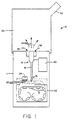
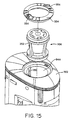
- a system 10 for dispersing a powder medicament from a plurality of receptacles 12 by insertion of a feed tube assembly 14 will be described.
- the receptacles may be in any form that holds and preserves the medicaments and which provides a puncturable access surface.
- receptacles 12 are in a continuous web comprising individual wells covered by a puncturable lid, typically a metal foil or other conventional laminate.
- Each receptacle will include a precise dosage of the powdered medicament to be delivered.
- the amount of powder in each individual receptacle will usually be in the range from about 1 mg to 20 mg, more usually being from 2 mg to 10 mg.
- the continuous web may be in the form of a strip, disk, or molded structure with a closure.
- the manufacture of such containers, often referred to as "blister packs" is well known in the pharmaceutical packaging art and need not be described further.
- the powder dispersion systems of the present invention could also be constructed to receive single dosage packages carrying only one receptacle.
- the user would insert the package so that the receptacle was properly oriented relative to feed tube 40 ( Fig. 2 ) of feed tube assembly 14.
- Necessary piercings in the access surface of the receptacle could be made manually prior to insertion, could be made within the system 10 (either prior to or simultaneous with introduction of the feed tube assembly 14) or could be preformed and exposed by peeling away a cover prior to insertion of the package into the device.
- receptacle packages could also be provided where the package is inserted into the device at different orientations in order to selectively expose individual receptacles to the feed tube.
- a variety of design options are available when the user inserts a single receptacle prior to each use.
- the system 10 further comprises a base enclosure 11, and the feed tube 40 ( Fig. 2 ) of feed tube assembly 14 has an inlet end 16 and an outlet end 18.
- a pressurized gas source 20 is provided within the base enclosure 11 and is connected to the proximal end of the feed tube assembly 14 to provide a high pressure gas stream, as will be described in greater detail in connection with Fig. 2 .
- the receptacles 12 will be mounted within the base enclosure 11 to reciprocate relative to the inlet end 16 of feed tube assembly 14.
- the strip of receptacles 12 will be mounted within a cartridge 22 which is reciprocatably mounted in the base enclosure 11, while the feed tube assembly 14 is fixedly mounted within the base enclosure.
- the receptacles 12 may be sequentially advanced past a fluidization location (defined by the inlet end 16 of feed tube assembly 14) within the cartridge 22, with the receptacle which is at the dispersion or fluidization location being brought proximate the inlet end 16 of the feed tube to permit emptying of its powdered contents, as described in more detail hereinafter.
- Both reciprocation of the cartridge 22, and advance of the receptacles 12 within the cartridge may be accomplished manually by the user.
- a mechanism may be provided within the base enclosure 11 for simultaneously reciprocating the cartridge 22 and advancing the strip of receptacles 12, either as part of a manual advance mechanism or as part of a battery-powered mechanism.
- penetrations will be formed in the lid of the strip of receptacles 12 by a piercing mechanism 24.
- the piercing mechanism 24 will be fixedly mounted within the base enclosure 11 and will include a plurality of sharpened penetrating elements 26 disposed to contact and penetrate the puncturable lid 92 ( Fig. 3 ) of the receptacles 12 when the cartridge 22 is reciprocated, as illustrated in broken line in Fig. 1 .
- the piercing mechanism 24 will be located to contact a receptacle 12 which is located one station prior to the feed tube assembly 14. Thus, each receptacle 12 will be pierced immediately prior to being advanced to the fluidization location.
- the cartridge 22 could be held stationary within the base enclosure 11 while each of the feed tube assembly 14 and piercing mechanism 24 could be reciprocated, either together or separately.
- the inlet end 16 of the feed tube assembly 14 could be configured to be self-penetrating (see Figs. 10 and 11A and 11B below). In the latter case, the desired pattern of penetrations would be formed in the puncturable lid of the receptacle 12 at the same time that the inlet end is engaged against or inserted into the interior of the receptacle.
- the present invention is not limited to any particular puncturing and advance mechanisms which might be employed.
- the gas source 20 will provide a volume of high pressure air or other gas to the outlet end 18 of the feed tube 40 ( Fig. 2 ) of feed tube assembly 14 in order to induce a flow of fluidization air, draw powder from the receptacles 12, and disperse the powder within the flowing gas stream.
- the high velocity air from the gas source will usually be directed past the outlet end 18, it will be appreciated that feed tube 40 could be extended past the high velocity gas stream inlet point, for example by providing side inlets in an elongate tube.
- the high velocity gas could actually combine with the fluidization air carrying the entrained particles within the feed tube itself.
- the feed tube 40 could define the mixing volume 60 ( Fig. 4A ), as described below.
- the gas source 20 will provide gas at a relatively high pressure, usually being sufficient to provide for sonic flow past the outlet end 18 of the feed tube assembly 14, typically being above 15 psig, usually being at least 20 psig, and preferably being in the range from 20 psig to 150 psig, and most preferably being in the range from 40 psig to 80 psig.
- the energy stored in the charge of high pressure gas will be sufficient to induce air flow through the feed tube 40 of feed tube assembly 14 which in turn draws fluidization air into the receptacle to fluidize and extract the expected weight of powdered medicament from the receptacle 12.
- the expanded volume of the charge will typically be in the range from about 2 ml to 25 ml (measured at STP), usually being in the range from about 4 ml to 15 ml.
- the volume of fluidization gas whose flow is induced through the feed tube assembly 14 by the high velocity gas stream will usually be from 2 ml to 100 ml, preferably from 4 ml to 60 ml, measured at STP. The specific manner in which the high pressure gas is flowed past the outlet end 18 of feed tube assembly 14 will be described in greater detail in connection with Fig. 2 .
- Gas source 20 may be in the form of a manual pump, an electric pump, a high pressure gas cylinder, or the like.
- manual pumps in hand-held powder dispersion devices is described in the patent and technical literature. See e.g., WO90/07351 .
- electric gas pumps, gas cylinder supplies, and two-fluid systems is also well within the skill in the art.
- the gas dispersion system 10 further includes a plume capture chamber 30 which is disposed over the outlet end 1 8 of feed tube assembly 14 in order to capture powder released from the tube.
- the plume chamber 30 will include a mouth piece 32 at its distal end and will have an internal volume sufficient to capture substantially all of the powder dispersion which is delivered from the feed tube assembly 14. Usually, the volume will be in the range from 50 ml to 1000 ml, preferably from 100 ml to 750 ml.
- the chamber 30 will also include an ambient air inlet (not shown), optionally a tangential inlet as described in co-pending Application Serial No. 07/910,048, the full disclosure of which is incorporated herein by reference. Alternatively, the air inlet can be axial or spiral, as described in connection with Figs. 7-9 , below.
- the powder dispersion will be introduced into the plume capture chamber 30, as illustrated by arrows 34. Air will be displaced through the mouthpiece 32, and optionally back through an annular lumen in the feed tube assembly 14, as indicated by arrows 36 and as will be described in more detail in connection with Fig. 2 .
- Such recycling of air from the plume capture chamber 30 as the fluidization gas enters greatly reduces the total volume of new gas being introduced to the system. The only new gas introduced (prior to patient inhalation) will be from the gas source 20.
- the patient will inhale the entire aerosolized dose through the mouthpiece 32 chased by ambient air through the chamber to extract all aerosolized medicament from the chamber.
- an orifice plate or other flow limiting element may be placed in the chamber air inlet path to slow inhalation and enhance the penetration depth of the powder particles. Inhalation of the additional air further assures that the powdered medicament will be efficiently dispersed and driven deeply into the alveolar regions of the lung where it is available for systemic absorption or localized delivery.
- the feed tube assembly 14 includes an inner tubular feed tube 40 which defines the inlet end 16 of the feed tube assembly 14 at its distal end and an outer coaxial tube member 42 which defines an annular lumen 44 for passing return air from chamber 30 back to the receptacle 12, as described in more detail hereinafter.
- Lumen 46 of the inner tubular feed tube 40 extends from the inlet end 16 to the outlet end 18 where a throat or constriction is optionally formed.
- the throat or constriction is not necessary for operation of the feed tube assembly 14, but it is the area (A 2 ) at the outlet end of the lumen 46 ( Fig. 4A ) which determines the performance characteristics of the feed tube, as described in more detail hereinafter.
- Dispersion gas from gas source 20 enters the feed tube assembly 14 through a port 50 connected to an annular plenum 52.
- the annular plenum 52 is connected to a pair of gas conduits 54 which direct converging gas streams into the flow path defined by lumen 46 of the feed tube 40.
- the angle at which the gas conduits 54 are oriented is chosen to provide a proper balance between the magnitude of the flow velocity induced in the powder stream drawn through lumen 46 and the magnitude of the shear forces which break up agglomerates in the powder as they pass from the outlet end 18 into an expansion section 58.
- the area (A 2 ) ( Fig. 4A ) of the throat 18 of the feed tube lumen 46 will typically be in the range from 0.5 mm 2 to 10 mm 2 , preferably being in the range from 1 mm 2 to 4 mm 2 .
- area (A 4 ) of the upstream portion of lumen 46 ( Fig. 4A ) is greater than A 2 . typically being from 0.6 mm 2 to 15 mm 2 .
- the upstream lumen 46 could have a uniform area along its entire length equal to the outlet end area (A 2 ), although such a construction would be less preferred.
- a mixing volume 60 having a uniform (non-expanding) cross-sectional area (A 3 ) and a length (L 2 ) is located immediately at the outlet end 18 of the feed tube 40.
- the cross-sectional area (A 3 ) is shown to be slightly larger than feed tube throat area( A 2 ) outlet, but this is not necessary.
- the exemplary area( A 3 ) is typically in the range from 0.6 mm 2 to 11 mm 2 .
- the length (L 2 ) is 1-5 times the diameter of the mixing volume 60 (for circular cross-sections), typically being in the range from 0.5 mm to 2 mm.
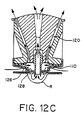
- a pair of gas conduits 54 Fig.
- FIG. 4B is shown, as illustrated in Fig. 4B . It would also be possible to utilize only a single inlet jet or to provide three, four or more separate inlets, with four inlets 54' being as illustrated in Fig. 4C . Other configurations will also be usable including a continuous annular aperture, as described in connection with Fig. 6 , or combinations of perpendicular jets (to break-up agglomerates) and axially directed jets (to induce fluidization gas flow).
- high pressure gas conduits 72 are arranged around the throat of a feed tube lumen 70 at angles ⁇ 1 , and ⁇ 2 , which will usually but not necessarily be equal.
- the angles ⁇ are important to achieving both adequate mass transfer of powder from the receptacle and adequate "agglomerate break up" as the powder enters the mixing volume immediately downstream from the outlet orifices of the conduits 72.
- the angles ⁇ will be in the range from 12.5° to 65°, preferably being from 25° to 40°.
- the high pressure gas lumens 72 may be formed as a single conical plenum 80 terminating in an annular aperture 82, as illustrated in Fig. 6 .
- the angle of convergence ⁇ will generally be within the range set forth above for ⁇ above, and the total area of the annular lumen 82 will generally be within the total area A 2 for the high pressure gas lumens also set forth above.
- the conical plenum 80 will have a width w in the range from about 0.005 mm to 0.1 mm.
- the feed tube assembly 14 operates by coupling the inlet end 16 of the feed tube 40 with an aperture 90 ( Fig. 3 ) formed into lid 92 over a receptacle 12.
- an aperture 90 ( Fig. 3 ) formed into lid 92 over a receptacle 12.
- the inlet end 16 is inserted through the lid 92 and into the receptacle 12, but is will also be feasible to engage the inlet end over the aperture 90, typically utilizing a sealing gasket as illustrated in Figs. 7-10 , below.
- the aperture 90 will be surrounded by space-apart apertures 94 (illustrated as six) which allow for the entry of fluidizing air as entrained powder is extracted through the inner feed tube 40.
- the aperture 90 is shown to be centered, but that is not necessary.
- At least a portion (and preferably all) of the fluidizing air will be provided through the annular lumen 44 via a port 96 in the feed tube assembly 14 disposal at the bottom of the interior of the plume chamber 30.
- Such "recycled" air from the plume chamber 30 passes through an annular plenum 98 from the port 96 into the annular lumen 44.
- a rubber flange or skirt 95 may be provided to prevent loss of fluidizing air from the lumen 44 to the receptacle 12.
- the recycling of fluidization air from the plume chamber 30 helps contain the plume of dispersed powder within the plume chamber since it limits the amount of air which is displaced and expelled through the mouthpiece 32 or other opening in the chamber.
- inlet end 16 of feed tube 40 of the feed tube assembly 14 into the receptacle 12 is advantageous (but not necessary) since it facilitates substantially complete removal of powder (usually at least 80% and preferably at least 90% by weight) from the interior of the receptacle. Such complete removal is further enhanced by the entry of fluidization air through the space-apart apertures 94, which creates an air flow pattern which can sweep powder from all corners of the receptacle into the dispersion lumen 46.
- FIG. 7-9 An alternative embodiment of a feed tube assembly 100 is shown in Figs. 7-9 .
- the feed tube assembly 100 is generally functionally equivalent to the feed tube assembly 14 and can be used in place thereof in the system of Fig. 1 .
- the feed tube 100 is particularly suitable for fabrication from molded plastic parts, or from a combination of molded plastic and fabricated metal parts.
- Feed tube assembly 100 comprises a casing 102, a gas flow-directing cone 104, a feed tube element 106, an end piece 108, a flexible valve element 110, and an end gasket 112.
- the feed tube element 106 is received in an open cavity 114 disposed in a lower end of the flow-directing cone 104.
- the flow passages within feed tube 106 will generally be the same as that described previously for feed tube assembly 14, and feed tube assembly 100 further includes a mixing volume 116 located immediately above the open cavity 114 and an expansion region 118 located above the mixing volume.
- the dimensions of the mixing volume 116 and expansion region 118 will generally be the same as those described previously in connection with the feed tube assembly 14.
- the flow directing cone 104 may include a plurality of air flow channels 120 formed over its exterior surface. Usually, there will be from 1 to 10 channels, having a total cross-sectional area from 5 mm 2 to 150 mm 2 , preferably from 40 mm 2 to 100 mm 2 .
- the air flow channels 120 are shown in a generally spiral pattern in Fig. 8 . The spiral pattern may be preferred since it will impart a vortical flow to replacement air entering the associated plume chamber as the patient inhales.
- the airflow channels 120 could also have a generally straight configuration which would impart a conically expanding, but not spiral, flow pattern to the replacement air.
- the airflow channels 120 are enclosed at their outward extremities by the inner surface 122 ( Fig. 9 ) of the casing 102.
- the air flow channels thus extend from a lower end 124 to an upper end 126, providing flow paths for replacement or "chase" air into a plume chamber, as described in more detail below.
- the flow paths provided by air channels 120 will also provide for recycling of air in the reverse direction from the plume chamber to an associated powder receptacle when the powder is being fluidized. This function will be described in more detail below.
- the end piece 108 includes a plurality of air flow apertures 126 located around a central opening 128.
- the flexible valve 110 lies over the air flow apertures 126 and is secured between the lower end of casing 102 and the upper surface of the end piece, as best seen in Fig. 9 .
- the flexible valve element 110 generally acts as a one-way valve, permitting entry of air from the outside of the feed tube assembly 100 into the region formed between the lower end of casing 102 and the end piece 108.
- High pressure air will be able to enter the open cavity 114 formed at the outlet end of feed tube element 106 through an inlet port 130 formed in the casing 102 ( Fig. 7 ).
- the flow path from port 130 to the cavity 114 is not shown in Fig. 9 .
- Supply of high pressure gas to the cavity 114 acts to induce the flow of fluidization air through the central lumen of the feed tube element 106 in a manner completely analogous to that described previously for feed tube assembly 14.
- a feed tube penetrating element 140 is disposed at the lower end of the feed tube 106. As shown in detail in Fig. 11 , the penetrating element 140 includes a pair of crossing internal walls 142 which terminate in a pointed blade structure 144. The blade structure 144 leaves four separate flow passages 146 arranged in quadrants within the feed tube 104. The flow passages 146 may optionally stop beyond the attachment point of the blade structure 144 to the inside wall of the host tube.
- a plurality of similar penetrating structures 150 are provided for both piercing the receptacle lid and simultaneously providing fluidization air inlet paths.
- the penetrating structures 150 may be provided in a carrier plate 152 or similar supporting structure.
- the penetrating structures 150 will have a similar conical blade structure to that described previously for the feed tube penetrating structure 140.
- the structure of Fig. 10 can provide for both the feed tube penetration and the peripherally arranged fluidization air penetrations in the penetrable lid of a medicament receptacle in a single motion where the lid is drawn against the gasket 112 of the feed tube assembly 100.
- Fig. 11B illustrates an alternative penetrating structure 151 formed by machining the end of a tube along two converging planes. The resulting pointed elements are then pressed together to form the structure having openings 153.
- the penetrating element 151 is advantageous since it peels back the lid as it is penetrated, leaving the openings 153 clear to receive powder.
- the penetrating structure 151 could be fabricated from molded plastic as well as machined metal.
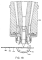
- a medicament receptacle R having preformed feed tube and fluidization air penetrations 200 and 202 is engaged against the gasket 112, as illustrated in Fig. 12A .
- Gasket 112 provides a seal against penetrable lid 204 of the receptacle R.
- the inlet end of feed tube 106 is shown to penetrate the lid 104, but it will be appreciated that such penetration is not essential since a seal will be provided by the gasket 112. Penetration may be desirable, however, since the lid flaps which surround the penetration 200 will be held open.
- a burst of high pressure air is introduced into the open cavity 114, as shown in Fig. 12B .
- the high pressure air flows past outlet end of the feed tube 106, inducing a flow of fluidization air through the receptacle R.
- fluidization air is drawn through the air flow channels 120 from the overlying plume chamber (not illustrated), as shown by arrows 210.
- the air drawn in through the air flow channels 120 enters the receptacle through penetrations 202, thus fluidizing the powder and drawing the powder out through the feed tube 106.
- the air flow through the feed tube thus entrains the powder and combines the powder with high pressure gas flow at the outlet end of the feed tube.
- the combined powder, fluidization air, and high pressure dispersion gas is then introduced into the plume chamber, as shown by arrows 212.
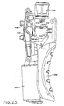
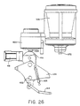
- the apparatus 300 includes a housing 302 and a capture chamber 304 that is slidable over the housing 302. Removably held within the housing 302 is a transjector assembly 306.
- the transjector assembly 306 is similar to the feed tube assembly 100 as shown in Figs. 7-9 and is employed to introduce aerosolized medicament into the capture chamber 304 as described in greater detail hereinafter.
- the apparatus 300 further includes a handle assembly 336 having a handle 338 that in combination with the transjector assembly 306 is employed to aerosolize the medicament and will be described in greater detail hereinafter.
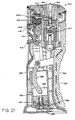
- the housing 302 further includes an aperture 340 for receiving a receptacle 342 (see Fig. 20 ) having the powdered medicament.
- the capture chamber 304 is sized to be slidably received over the housing 302 so that the capture chamber 304 may be removed from the housing 302 for cleaning and also so that chamber 304 can be translated between a deployed position (see Fig. 20 ) and a retracted position (see Fig. 14 ).
- the capture chamber 304 forms an enclosure for receiving aerosolized medicament introduced by the transjector assembly 306 so that it may be inhaled by a patient.
- the capture chamber 304 can be slid over the housing 302 to the retracted position for storing.
- two pairs of detent pins 308 and 310 are provided.
- the detent pins 308, 310 are received into slots 312 and 314 in the housing 302. Springs 316 and 318 are preferably provided to outwardly bias the detent pins 308, 310.
- the capture chamber 304 includes a chamber body 320 having a bottom portion 322 and a top portion 324. Included in the bottom portion 322 are a pair of grooves (not shown) for engaging the detent pins 308, 310.
- the detent pins 308 are received in the grooves when the capture chamber 304 is in the deployed position, and the detent pins 310 are received into the grooves when the capture chamber 304 is in the retracted position.
- the detent pins 308 and 310 each include a V-shaped portion 326 and 328 for engaging the grooves in the bottom portion 322 of the capture chamber 304.
- the particular angle and orientation of the V-shaped portions 326 and 328 can be varied to increase or decrease the amount of force required to deploy or retract the capture chamber 304.
- the mating grooves on the chamber 204 may also be provided with different angles to assist in achieving this effect.
- the detent pins 310 will be configured so that it is easier to translate the chamber 304 downward toward the bottom of the housing 302 than to translate the chamber 304 upward toward the top of the housing 302.
- the chamber 304 may be placed in the retracted or storage position with a relatively small force, while a relatively greater force will be required to retrieve the chamber 304 from the storage position. In this way, the chamber 304 will be configured to not inadvertently slide open during non-use.
- the detent pins 308 will usually be configured so that a greater force is required to altogether remove the chamber 304 from the housing 302 than to slide the chamber 304 down over the housing toward the detent pins 308. In this way, inadvertent removal of the chamber 304 will be prevented when sliding the chamber 304 to the deployed position.
- the capture chamber 304 is preferably asymmetrical in cross-sectional geometry so that the capture chamber 304 may be repeatedly placed over the housing 302 at a known orientation. This is particularly advantageous in insuring that an inhalation port 330 of a mouthpiece 331 (see Fig. 14 ) is properly positioned relative to a fire button 418 (see Fig. 21 ) that is employed to introduce the powdered medicament into the capture chamber 304.
- the chamber body 320 will preferably include at least one elongate ridge 324 extending longitudinally along the length of the interior of the chamber body 320.
- the ridge 334 is provided to contact the housing 302 and to keep the remainder of the chamber body 320 spaced-apart from the housing 302 when the capture chamber 304 is translated to the retracted position. Often, residual powder will remain on the interior walls of the chamber body 320 after use. As the chamber body 320 is slid over the housing 302 to retract the capture chamber 304, the ridge 334 contacts the housing 302 to limit the amount of residual powder that is scraped from the chamber body 320 by the housing 302. Extensive scraping of the accumulated powder from the walls of the chamber body 320 is undesirable in that the scraped powder may become agglomerized and may interfere with the subsequent operation of the apparatus 320.
- a raised portion 335 is provided on the housing 302 to insure a proper fit between the bottom portion 322 and the housing 302.
- the chamber body 320 is preferably constructed of a transparent material and will usually be constructed of plastic.
- the plastic may be an inherently conductive polymer such as that described in U.S. Patent Nos. 5,342,889 , 5,348995 , and 4,719263 , the disclosure of which is herein incorporated by reference, to limit the amount of electric charge built up on the walls of the chamber body 320 during use.
- the capture chamber 304 is shown in the retracted position and will be used to describe operation of the inhalation port 330 in greater detail.
- the capture chamber 304 includes a cover 344 that may be closed over the inhalation port 330.
- the cover 344 is employed to prevent external dust or particulate from entering into the interior of the capture chamber 304 during storage and also to hold the aerosolized medicament introduced by the transjector assembly 306 within the chamber 304 until ready for inhalation.
- the cover 344 may include seal 346 which is received over the inhalation port 330 when the cover 344 is closed. When introducing the aerosolized medicament, the pressure within the capture chamber 304 is increased.
- the seal 346 serves as a bleed valve to allow some of the pressurized gas within the chamber 304 to spontaneously escape. Reducing the chamber pressure in this manner is advantageous in preventing a "puff" of medicament from escaping when the cover 344 is lifted for inhalation.
- the capture chamber 304 will preferably define an enclosed volume of about 50 ml to 750 ml, and more preferably at about 100 ml to 250 ml.
- 8 ml of gas introduced into a 210 ml chamber will amount to a pressure rise of about 0.6 psi.
- the seal 346 is preferably constructed of silicone, urethane or similar flexible elastomers, although a similar functioning valve could be achieved with a spring loaded rigid valve element such as a thin mylar or metal petal or plate.
- the housing 302 includes a cylindrical opening 348 that is sized to receive the transjector assembly 306.
- the opening 348 includes a keyed slot 350 for receiving a keyed portion 352 of the assembly 306.
- the keyed slot 350 is provided so that the transjector assembly 306 may be repeatedly placed in a known orientation when the transjector assembly 306 is inserted into the opening 348.
- a locking nut 354 is provided to secure the transjector assembly 306 into the opening 348.
- the locking nut 354 includes a pair of tabs 356 to allow for easier rotation of the nut 354 when securing or unlocking the nut 354.
- the nut 354 is unscrewed and removed, and the transjector assembly 306 is lifted from the housing 302.
- the nut 354 may be configured to snap fit into the opening 348 to hold the transjector assembly 306 in place.
- the transjector assembly 306 includes a casing 358, a gas flow directing cone 360, a feed tube element 362, an end piece 364, a flexible valve element 366, and an end gasket 368.
- the transjector assembly 306 operates substantially identical to the feed tube assembly 100 as shown in Figs. 7-9 in extracting and aerosolizing the powdered medicament in the receptacle.
- the transjector assembly 306 differs from the feed tube assembly 100 in that the transjector assembly 306 includes an alternative penetrating element 370 and a pair of penetrating structures 372.
- the penetrating element 370 is disposed at the lower end of the feed tube 362 and is employed to extract powder from the receptacle 342 as previously described in connection with the feed tube assembly 100 when the penetrating element 370 is introduced into the receptacle 342.
- the penetrating structures 372 are provided for both piercing the receptacle lid and simultaneously providing fluidization air inlet paths.
- a particular advantage of the penetrating structures 372 is that they are easy to manufacture, thereby reducing the overall cost of the transjector assembly 306.
- the penetrating structures 372 may optionally be provided with a plurality of points rather than a single point to facilitate penetration into the receptacle lid.
- the receptacle 342 includes a receptacle body 374 having a penetrable lid 376 covering an enclosure 378 and a tab 380. Within the tab 380 is a hole 382 for aligning the receptacle 342 with the transjector assembly 306 as described in greater detail hereinafter.
- the receptacle 342 is lifted (or the transjector 306 is lowered) until the penetrating element 370 and the penetrating structures 372 pierce the lid 376 as shown in Fig. 19 .
- the penetrating structures 372 are angled relative to the penetrating element 370 and operate similar to can openers to peel back a portion of the lid 376 and form the air inlet paths.
- a burst of high pressure air is introduced into an open cavity 384 which flows past the outlet end of the feed tube 362 to draw the powdered medicament within the receptacle 342 through the transjector assembly 306 in a manner similar to the feed tube assembly 100 described in Figs. 12-12C .
- the end gasket 368 contacts the receptacle body 374 and forms a seal against the receptacle 342.
- the receptacle 342 is delivered into the aperture 340 by grasping the tab 380 and inserting the receptacle body 374 into the aperture 340 until stop shoulders 375 on the receptacle body 374 engages guide pins 377 (see also Fig. 21 ) on which a carrier 442 (see also Fig. 22 ) rides and prevents further translation.
- the hole 382 is generally aligned with a pin 386.
- the receptacle 342 is then lifted within the aperture 340 until the hole 382 is received over the pin 386 which guides and aligned the receptacle 342 until engaging the end gasket 368 (see Fig. 19 ).
- the tab 380 remains outside the housing 302. In this way, premature closure of the capture chamber 304 is prevented since the tab 380 will prevent retraction of the capture chamber 304.
- the tab 380 thus ensures that the capture chamber 304 will always be in the deployed position when the receptacle 342 is loaded into the apparatus 300. Thus, the capture chamber 304 must always be in the deployed position for the receptacle 342 to be loaded into the apparatus 300.
- the pin 386 may be keyed to fit only a specific hole configuration in the receptacle 342.
- the apparatus may be configured to receive only specific receptacles having a given medicament:
- a plurality of pins and corresponding holes in the receptacle may be provided to key the apparatus 300.
- the handle 338 on the handle assembly 336 is operably connected to a piston 388 that in turn is translatably held within a cylinder 390.
- a linkage 392 is provided to connect the piston 388 to the handle 338.
- the linkage 392 is pulled from the cylinder 390 to lift the piston 388.
- the piston 388 is in a retracted position.
- the piston 388 is translated within the cylinder 390 to pressurize the gas within the cylinder 390.
- the cylinder includes a one-way valve 394 that is held within a retainer 396.
- the one-way valve 394 is preferably a "duck bill" type valve which allows air into the cylinder 390 as the piston 388 is translated to the extended position.
- the valve 394 is closed to prevent air from escaping from the cylinder 390 through the valve 394.
- Pressurized air from the cylinder 390 is passed via a transfer or an outlet tube 398 (see Figs. 21 and 25 ) to a release valve assembly 400.
- the release valve assembly 400 is in turn in communication with the transjector assembly 306 so that pressurized gas may be supplied to the open cavity 384 as previously described in Fig. 19 .
- a seal 402 is provided between the valve assembly 400 and the transjector assembly 306 to prevent high pressure air supplied from the valve assembly 400 from escaping between the interface between the valve assembly 400 and the transjector assembly 306.
- the seal 402 is preferably constructed of urethane, silicone, or a similar elastomer, and is angled relative to a longitudinal axis of the transjector assembly 306. In this way, the transjector assembly 306 may easily be inserted and removed to and from the housing 302 while at the same time allowing for a sufficient interface seal.
- the valve assembly 400 includes a valve stem 404 and a valve poppet 406 for selectively preventing air from flowing through the assembly 400 and will be described in greater detail hereinafter with reference to Figs. 27-29 .
- the valve assembly 400 is shown in the open position, with the poppet 406 being unseated. In such a configuration, gas within the cylinder 390 will not be significantly compressed upon translation of the piston 388 since air within the cylinder 390 will escape through the outlet tube 398.
- the valve assembly 400 is closed, air is prevented from escaping from the outlet tube 398 so that only a "full stroke" of air within the cylinder 390 may be compressed.
- the apparatus 300 is configured to close the valve assembly 400 as the piston 388 reaches the extended position so that air within the cylinder 390 may be compressed when the handle 338 is translated back toward the housing 302.
- the handle assembly 336 includes a linkage 408 (see Fig. 22 ) having rack 410 securely attached thereto.
- the rack 410 includes an elongate slot 412 for receiving a valve reset link 414 (see Figs. 21 and 24 ).
- the reset link 414 is pivotally attached to a roller cam 416.
- the roller cam 416 is pivotally attached to a valve release button 418.
- the linkage 408 pivots about a pin 420 causing the reset link 414 to slide within the slot 412 until reaching a left-hand end of the slot 412.
- the reset link 414 is translated in the direction of the handle 338 to pivot the roller cam 416 about pin 422.
- Further translation of the handle 338 causes the roller cam 416 to lock over center.
- the release button 418 is translated outward from the housing 302 and the valve stem 404 is driven upwards by the roller to seat the poppet 406 against a seat 452 (see Fig. 29 ), thereby closing the valve assembly 400.
- the piston 388 is translated via linkage 392 to the extended position.
- the reset link 414 slides within the slot 412 while the cam 416 remains over center to keep the valve assembly 400 closed.
- the piston 388 is translated within the cylinder 390 to compress the air within the cylinder 390.
- the apparatus 300 may be configured to prevent translation of the handle 338 back toward the housing 302 until the handle 338 is fully extended to place the cam 416 over center and close the valve 400.
- the handle assembly includes an interlock pawl 424 (see Fig. 22 ) for engaging ratchet teeth 426 on the rack 410.
- the pawl 424 engages the teeth 426 of the rack 410 to prevent closure of the handle 338 until the cam 416 moves over center to close the valve assembly 400.
- An interlock pawl spring 425 is provided to bias the pawl 424 against the ratchet teeth 426 until the cam 416 is over center.
- an interlock may be provided to prevent piercing of the receptacle 342 by the transjector assembly 306 until the valve assembly 400 is closed.
- the handle assembly 336 further includes a linkage 430 that is pivotally connected to the housing 302 by pin 432. connecting the handle 338 to linkage 392 and linkage 408 is a linkage 434.
- linkages 392, 408, 430 and 434 provide a four-bar linkage system which allow the handle 338 to be moved radially outward from the housing 302 with the handle 338 being maintained generally parallel to the housing 302. Further, when the valve assembly 400 is closed and the handle 338 is translated back toward the housing 302, a substantially uniform force is required over the handle's range of motion.
- the apparatus 300 further includes a carriage assembly 436 for translating the receptacle 342 within the aperture 340 so that the penetrating element 370 and the penetrating structures 372 may pierce the lid 376 of the receptacle 342.
- the carriage assembly 436 includes a thumb toggle 438 that is pivotally connected to the frame of the housing 302 by a pin 440.
- the receptacle 342 is held within a carrier 442 which in turn is connected to the thumb toggle 438 by a linkage 444. Operation of the carriage assembly 436 is as follows. Initially, the receptacle 342 is inserted into the aperture 340 as previously described with the receptacle 342 resting on the carrier 442.
- the thumb toggle 438 is then depressed to pivot the toggle 438 about pin 440 and to lift the carrier 442 toward the transjector assembly 306.
- the thumb toggle 438 is depressed until the transjector assembly 306 pierces the lid on the receptacle 342 and the linkage 444 moves over center.
- the linkage 444 is over center, the receptacle 342 is locked in place against the end gasket 368 of the transjector assembly 306 (see Fig. 25 ).
- the carriage assembly 436 will be configured to compensate for overtravel of the carrier 442.
- the carrier 442 will be relaxed after the receptacle 342 has been pierced by the transjector assembly 306 but will still provide a sufficient seal between the transjector assembly 306 and the receptacle 342.
- the thumb toggle 438 is lifted to move the linkage 444 from over center.
- the receptacle 342 may then be removed from the aperture 340 by grasping the tab 380 and pulling the receptacle 342 from the aperture 340.
- the valve assembly 400 includes a casing 446 having an inlet port 448 and an outlet port 450.
- the outlet tube 398 which connects the cylinder 390 to the valve assembly 400 passes through the inlet port 448.
- the interface seal 402 is placed between the outlet port 450 and the transjector assembly 306 as previously described.
- the valve assembly 400 is shown in the open state in Fig. 28 .
- the poppet 406 When open, the poppet 406 is spaced apart from an O-ring seat 452.
- the poppet 406 is held within a central chamber 454 which is sealed from the outside environment (except for the outlet port 450) by a diaphragm 456.
- air introduced into the central chamber 454 from the outlet tube 398 freely passes around the poppet 406 and exits the outlet port 450.
- air introduced into the central chamber 454 from the outlet tube 398 forces the poppet 406 against the seat 452 which prevents escape of the compressed air from the central chamber 454.
- the valve assembly 400 is preferably configured so that the seal between the poppet 406 and the seat 452 will hold up to about 120 psi of pressure, and more preferably at about 80 psi.
- the release button 418 is depressed to move the cam 416 from over center and to allow the poppet 406 to be moved away from the seat 452.
- a spring 457 is provided.
- the spring 457 will preferably be selected to provide a force sufficient to overcome the force on the opposite side of the poppet that is produced by the compressed air within the chamber 454. Hence, when the release button 418 is depressed, the spring 457 will overcome the force produced by the compressed air within the chamber 454 and will promptly force the poppet 406 away from the seat 452 and allow the valve to open.
- valve assembly 400 operates in a "snap" acting manner to provide a precise amount of gas to the transjector assembly 306 in a rapid, abrupt and irreversible manner so that the powder may be sufficiently aerosolized in a repeatable and a predictable manner.
- the housing 302 may further include an electronic memory chip along with a speaker for providing audible instructions to a user regarding operation of the apparatus 300.
- the chip will preferably be an EPROM, PROM, or PAL chip having stored electronic information regarding operation of the apparatus 300 and will be configured to be actuated upon deployment of the capture chamber 304. In this way, as a user prepares for a treatment, audible instructions will be given. Preferable instructions include deployment of the chamber 304, charging of the apparatus with the handle assembly 336, breathing instructions, and the like, as well as other pertinent information as determined by the manufacturer.
Abstract
Description
- The present invention relates generally to methods and apparatus for the pulmonary delivery of drugs. More particularly, the present invention relates to a method and apparatus for dispersing dry powder medicaments for inhalation by a patient.
- Effective delivery to a patient is a critical aspect of any successful drug therapy. Various routes of delivery exist, and each has its own advantages and disadvantages. Oral drug delivery of pills, capsules, elixirs, and the like, is perhaps the most convenient method, but many drugs are degraded in the digestive tract before they can be absorbed. Such degradation is a particular problem with modern protein drugs which are rapidly degraded by proteolytic enzymes in the digestive tract. Subcutaneous injection is frequently an effective route for systemic drug delivery, including the delivery of proteins, but enjoys a low patient acceptance. Since injection of drugs, such as insulin, one or more times a day can frequently be a source of poor patient compliance, a variety of alternative routes of administration have also been developed, including transdermal, intranasal, intrarectal, intravaginal, and pulmonary delivery.
- Of particular interest to the present invention, pulmonary drug delivery relies on inhalation of a drug dispersion or aerosol by the patient so that active drug within the dispersion can reach the distal (alveolar) regions of the lung. It has been found that certain drugs are readily absorbed through the alveolar region directly into blood circulation. Pulmonary delivery is particularly promising for the delivery of proteins and polypeptides which are difficult to deliver by other routes of administration. Such pulmonary delivery is effective both for systemic delivery and for localized delivery to treat diseases of the lungs.
- Pulmonary drug delivery (including both systemic and local) can itself be achieved by different approaches, including liquid nebulizers, metered dose inhalers (MDI's) and dry powder dispersion devices. Dry powder dispersion devices are particularly promising for delivering protein and polypeptide drugs which may be readily formulated as dry powders. Many otherwise labile proteins and polypeptides may be stably stored as lyophilized or spray-dried powders by themselves or in combination with suitable powder carriers. The ability to deliver proteins and polypeptides as dry powders, however, is problematic in certain respects. The dosage of many protein and polypeptide drugs is often critical so it is necessary that any dry powder delivery system be able to accurately, and precisely (repeatedly) deliver the intended amount of drug. Moreover, many proteins and polypeptides are quite expensive, typically being many times more costly than conventional drugs on a per-dose basis. Thus, the ability to efficiently deliver the dry powders to the target region of the lung with a minimal loss of drug is critical. It is further desirable that powder agglomerates present in the dry powder be sufficiently broken up prior to inhalation by the patient to assure effective systemic absorption or other pulmonary delivery.
- A particularly promising approach for the pulmonary delivery of dry powder drugs utilizes a hand-held device with a pump or other source of pressurized gas. A selected amount of the pressurized gas is abruptly released through a powder dispersion device, such as a Venturi tube, and the dispersed powder made available for patient inhalation. While advantageous in many respects, such hand-held devices are problematic in a number of other respects. The particles being delivered are very fine, usually being sized in the range from 1µm to 5µm, making powder handling and dispersion difficult. The problems are exacerbated by the relatively small volumes of pressurized gas, typically 2 ml to 25 ml at 20 to 150 psig, which are available in such devices. In particular, Venturi tube dispersion devices are unsuitable for difficult-to-disperse powders when only small volumes of pressurized gas are available. Moreover, Venturi tube dispersion devices have very small powder inlet orifices which are easily plugged by the powders used for pulmonary delivery. Another requirement for hand-held and other powder delivery devices is high dosage concentration. It is important that the concentration of drug in the bolus of gas be relatively high to reduce the number of breaths and/or volume of each breath required to achieve a total dosage. The ability to achieve both adequate dispersion and small dispersed volumes is a significant technical challenge.
- It would therefore be desirable to provide methods and systems for the dispersion of dry powder protein, polypeptide, and other drugs which meet some or all of the above objectives.
- Dry powder dispersion devices for medicaments are described in a number of patent documents.
U.S. Patent 3,921,637 describes a manual pump with needles for piercing through a single capsule of powdered medicine. The use of multiple receptacle disks or strips of medication is described inEP 467172 WO91/02558 WO93/09832 WO94/08522 US Patent Nos. 4,627,432 ;4,811,731 ;5,035,237 ;5,048,514 ;4,446,862 ; and3,425,600 . Other patents which show puncturing of single medication capsules include4,338,931 3,991,761 4,249,526 4,069,819 4,995,385 4,889,114 4,884,565 EP 469814 WO90/07351 - A dry powder sonic velocity disperser intended for industrial uses and very high flow rates is described in Witham and Gates, Dry Dispersion with sonic Velocity Nozzles, presented at the Workshop on Dissemination Techniques for Smoke and Obscurants, Chemical Systems Laboratory, Aberdeen Proving Ground, Maryland, March 14-16, 1983.
- A pneumatic powder ejector having a suction stage and an injection stage is described in
U.S. Patent No. 4,807,814 . The device comprises an axial gas venturi tube and a lateral powder inlet. - Pittman and Mason (1986), Solids Handling Conference, Paper C4, pages C-41 to C-51, describes an ejector nozzle (
Fig. 2 ) having an annular air inlet upstream of a venturi restriction. -
SU 628930 -
SU 1003926 - Bubrik and Zhelonkina (1978), "Ejector Feeders for Pneumatic Transport Systems," in Chemical and Petroleum Engineering, Consultants Bureau, New York, describes differing efficiencies in several ejector designs.
- Zholab and Koval (1979), Poroshkovaya Metallurgiya 6:13-16, describes effects of injector design on particle size.
- Bohnet (1984) "Calculation and Design of Gas/Solid-Injectors," in Powder Technology, pages 302-313, discusses conventional injector design.
- Fox and Westawag (1988) Powder and Bulk Engineering, March 1988, pages 33-36, describes a venturi eductor having an axial air inlet tube upstream of a venturi restriction.
-
NL 7712041 -
EP 347 779 -
EP 490 797 -
U.S. Patent No. 3,994,421 , describes a hand-held powder disperser having a collapsible deceleration chamber. - Pulmonary drug delivery is described in Byron and Patton (1994) J. Aerosol Med. 7:49-75.
- The present invention provides methods and apparatus for efficient pulmonary delivery of accurate, precise, and repeatable dosages of powdered medicaments. The present invention will be particularly useful for the delivery of costly biopharmaceuticals such as protein, polypeptide and polynucleic acid drugs, but will also be useful for the systemic or localized delivery of any powdered medicament through the lungs. The delivery system and method produce substantially complete dispersion of the medicament powder with the break-up of any agglomerates of the powder which may have formed prior to delivery. The method and apparatus will find particular use in the dispersion of finely powdered medicaments from unit dosage receptacles, such as blister packs or cartridges, where the present invention is able to fluidize and extract substantially the entire amount of powder (usually at least 70% by weight, more usually at least 80%, and preferably at least 90%) within the receptacle, thus minimizing waste and enhancing the accuracy and precision of the dosage. The methods and approaches, however, will also find use with the dispersion and delivery of preselected metered amounts (boluses) of powdered medicaments from receptacles containing multiple dosage units, i.e. "bulk" powders contained in a single receptacle.
- The methods and apparatus of the present invention are particularly suitable for the delivery of powders formed from discrete particles in the size range from 1µm to 5µm. Such powders, when properly dispersed in an aerosol, are optimum for delivery into the alveolar regions of the lung. However, they are particularly difficult to handle, and frequently become highly agglomerated during processing, packaging, and handling. Heretofore, handling characteristics of such powders have often been enhanced by combining the fine drug particles with larger carrier particles which have easier handling and dispersion characteristics. Use of a carrier, however, dilutes the drug, requiring a larger dispersion volume for a given drug dosage. The carrier particles can also cause choking when inhaled and serve no purpose other than improving handling characteristics. The present invention is able to achieve dispersion of fine drug particles with little or no carrier substances by a two-step dispersion method. The present invention, however, will be functional with drug compositions which include such carrier particles, as well as with diluents which may be necessary to achieve desired dosage concentrations.
- The powders are first fluidized within the receptacle, as described above, resulting in fluidized particles and particle agglomerates which are then dispersed in the high velocity gas stream under conditions which break up such agglomerates. Such complete dispersion can be achieved with very low volumes of high velocity air and fluidization air, resulting in a well dispersed drug bolus having relatively high drug particle concentrations. Of course, the present invention is useful as well with drug formulations including a carrier diluent, or the like. The advantage of the present invention is that the use of carriers can often be reduced or eliminated altogether.
- According to the method of the present invention, the powdered medicament is contained in a receptacle having a puncturable lid or other access surface. A powder inlet end of a feed tube is coupled with, i.e. engaged against or inserted through, a penetration in the access surface, and a high velocity airstream (usually sonic which provides sufficient shear forces to separate agglomerates into individual particles) is flowed past a portion of the tube, such as an outlet end, to draw powder from the receptacle, through the tube, and into the flowing airstream to form the desired aerosol. Usually, at least two spaced-apart discrete penetrations will be formed in the access surface prior to coupling the inlet end of the feed tube with one of the penetrations. The other penetration permits a separate stream of fluidization air to enter the receptacle, fluidize the powder, and sweep the receptacle of the fluidized powder to help assure that substantially all powder (preferably at least 70%, more preferably at least 80%, and still more preferably at least 90%) is removed into the flowing air stream. The high pressure gas stream will be generated by abruptly releasing a charge of pressurized gas through a flow path which intersects with the outlet end of the feed tube at an angle selected to both (1) induce sufficient fluidization air flow through the feed tube to fluidize and transport powder in the receptacle and (2) break up powder agglomerates which remain as the powder exits from the outlet end of the feed tube. The gas pressure prior to release will usually be at least about 15 psig (to achieve sonic velocity), preferably being at least 20 psig, and more preferably being in the range from 20 psig to 150 psig, and usually being in the range from 40 psig to 80 psig. The expanded volume of released gas (measured at standard temperature and pressure (STP) of 14.7 psig and 20°C) will thus usually be in the range from 2 ml to 25 ml, preferably being from 4 ml to 15 ml. Release of the high pressure gas can be effected by a manual trigger or optionally by sensing negative pressure resulting from the patient's inspiration (i.e., can be breath-activated). As described in detail below, the high pressure gas stream will combine with the fluidization air stream at a volume ratio (measured at STP) in the range from 1:2 to 1:4 (high pressure gas: fluidization air) to produce the aerosol which is subsequently inhaled by the patient, optionally after capture in a plume capture chamber.
- The method may further comprise the step of capturing the resulting discrete volume of aerosolized powder in a plume capture chamber prior to subsequent inhalation by the patient. The patient is then able to inhale the entire aerosolized dose from the chamber, concurrently with and/or followed by inhalation of ambient air which sweeps the capture chamber to further assure efficient delivery of the powder with minimum losses. Inhalation of chase air following the initial bolus of medication will drive the medication deep into the alveolar regions of the lung where absorption will occur. The method optionally further comprises advancing a plurality of powder-containing receptacles past the feed tube, typically in the form of a strip or disk, so the powder can be sequentially drawn and dispersed from each receptacle.
- In another aspect of the method of the present invention, discrete quantities of a powdered medicament may be sequentially delivered from a receptacle or reservoir. In contrast with the previously described methods, the receptacle will include an amount of powdered medicament which is larger than that intended to be delivered in any single bolus, usually containing an amount which is sufficient for a large number of boluses, usually at least 5, preferably at least 10, and frequently 20 or more. The method comprises inserting the inlet end of the feed tube into the receptacle and flowing a high pressure gas stream past an outlet end of the feed tube to induce airflow from the receptacle through the tube. The powdered medicament is thus entrained in the airflow passing through the feed tube and combined with the high pressure gas stream at an outlet end of the feed tube. The high pressure gas stream can be repeatedly directed past the outlet end of the feed tube while the inlet end remains within the "bulk" powdered medicament receptacle.
- Apparatus according to the present invention comprise a base enclosure having a support for the powder-containing receptacle at a fluidization location. The feed tube is mounted within the base enclosure and a mechanism for reciprocating the receptacle relative to the feed tube (or extending the feed tube relative to the receptacle) is optionally provided. A source of compressed gas for generating the high pressure gas is also provided, typically in the form of a hand-actuated pump, an electric (usually battery-operated) pump, a compressed gas container, a two-fluid system, or the like. The aerosolized powder dosage may thus be formed by reciprocating the receptacle relative to the feed tube so that the inlet end of the tube enters the receptacle. The high pressure gas stream is released while the tube is in or adjacent to the receptacle, and the resulting low pressure region at the outlet end of the feed tube draws fluidization air into the receptacle (preferably from the plume capture chamber which subsequently receives the aerosol, thus minimizing net air introduced from outside the device) to fluidize and extract the powder outward from the receptacle through the tube, and into the high velocity gas stream to form the desired dispersion. Usually, the capture chamber is disposed over and in-line with the outlet end of the feed tube to contain the "plume" of powder aerosol and allow the plume to quiesce prior to inhalation by the patient. The feed tube does not have jets or ejector tubes within the flow path, and the clear, undisrupted flow path reduces any tendency for the feed tube to clog or otherwise lose dispersion efficiency. Using air from the capture chamber as a source of fluidization gas is advantageous since it reduces the total volume of "new" gas introduced to the chamber, making capture of the dispersion gas stream (i.e., the combination of the high pressure gas stream and the fluidization air stream) easier. Such recycling of air from the capture chamber, however, is not an essential feature of the present invention. Fluidization air can also be obtained directly from outside the device.
- In a particular aspect of the apparatus of the present invention, the receptacle will be supported in a mechanism for advancing a continuous web (e.g. a strip or disk) which carries a plurality of receptacles past the fluidization location. Usually, the web advance mechanism includes a cartridge or carriage which holds the web and which is reciprocatably mounted relative to the feed tube so that the receptacles may be sequentially advanced while the cartridge and tube are separated, and the tube thereafter introduced into the receptacle by moving the cartridge and tube together. Optionally, the receptacle lid or other single access surface (i.e., a surface on one side of the receptacle) will be pierced immediately prior to introduction of the feed tube, usually using a separate piercing mechanism which pierces the lid as the cartridge is reciprocated relative to the feed tube. Alternatively, the access surface can be pierced simultaneously with the insertion of the feed tube. In the latter case, the inlet end of the feed tube will usually have a piercing structure and/or additional piercing structures will be provided to form additional penetrations for the entry of the fluidization air.
- In a specific aspect of the apparatus of the present invention, the piercing mechanism will produce at least two spaced-apart holes in the lid, where one hole receives or engages the feed tube and the other hole(s) permit entry of displacement air to fluidize the powder and sweep the receptacle as powder is withdrawn through the feed tube. A conduit or other path may also be provided for directing air from the plume capture chamber back to the receptacle in order to at least partially provide the necessary displacement air. The hole for the feed tube may be formed simultaneously with or at a different time from the displacement air hole(s). For example, the displacement air hole(s) could be formed at a piercing station disposed ahead of the dispersion station with the feed tube hole formed at the dispersion station, or vice versa. It also may be desirable to provide a piercing mechanism at the dispersion station where the feed tube piercing structure is reciprocated relative to the receptacle in a separate motion from the displacement air hole piercing structure.
- The present invention further provides apparatus for aerosolizing of powder comprising a feed tube having an inlet end, an outlet end, and a lumen defining an axial flow path between said inlet end and outlet end. At least one conduit is provided for flowing a high velocity gas stream past the outlet end in a direction which converges with the axial flow path at an angle in the range from 12.5° to 65°. It has been found that the angle of convergence in this range induces a sufficient flow of fluidization air in the feed tube to efficiently empty an associated powder receptacle (typically removing and aerosolizing at least 80% and preferably at least 90% of the powder initially present in the receptacle) while also providing sufficient shear energy at the outlet end to substantially break up agglomerates which are present in the powder.
- The aerosolizing apparatus may include two or more separate gas conduits which converge from different, usually opposite (diametrically opposed), sides of the flow path. Alternatively, the high pressure gas conduit may terminate in a single annular aperture which circumscribes the outlet end of the feed tube and which creates a gas flow path which converges on the axial flow path. The latter approach however, will generally be less preferred since it is difficult to manufacture annular apertures in the small size required. The total lumen area (A1) of the high pressure (dispersion) gas flow conduit(s) will usually be in the range from 0.05 mm2 to 0.3 mm2, while the throat of the feed tube immediately upstream of the gas conduit(s) tube will have a lumen area (A2) in the range from 0.5 mm2 to 10 mm2. The area (A3) and length of the mixing volume immediately downstream from the high velocity gas conduits are preferably in the range from the 0.6 mm2 to 11 mm2 and 0.5 mm to 3 mm, respectively. The feed tube upstream of the throat will usually have an area (A4) in the range from 0.6 mm2 to 15 mm2.
- The aerosolizing apparatus may further include a diffuser tube extending from the outlet end of the mixing volume and having a lumen which is usually but not necessarily coaxially aligned with the feed tube lumen. The diameter of the diffuser tube lumen will increase in a direction away from the outlet end of the mixing volume, typically diverging at a half angle of 2° to 10° over a length in the range from 0.5 cm to 5 cm, usually having an outlet area which is about four times the inlet (mixing volume) area. The diffuser tube thus causes a reduction in the velocity of the gas stream exhausted from the outlet end of the mixing volume, where velocity is at a maximum, prior to entering the plume capture chamber. The plume continues to slow rapidly as it expands within the chamber and approaches a quiet or quiescent state prior to inhalation.
- The present invention further provides a feed tube assembly comprising a casing, a flow-directing member, and a feed tube. The assembly is replaceable within the aerosol dispersion system, facilitating removal and cleaning or exchange of the assembly if it becomes plugged or fouled.
- The invention provides an improved apparatus for aerosolizing a powdered medicament. The apparatus is of the type having a housing and a source of pressurized gas for aerosolizing the powder. Such an apparatus is improved by providing a pressurization cylinder, a piston slidable within the cylinder, and a release valve in communication with the cylinder. Further provided is a handle assembly having a handle operably attached to the piston and a means for closing the valve. In this manner, translation of the handle closes the valve and axially translates the piston within the cylinder to produce the pressurized gas.
- In one aspect, the release valve comprises a valve stem connected to a valve poppet, and the means for closing the valve comprises a roller cam adjacent the valve stem for translating the valve stem to close the valve as the handle is translated radially outward from the housing. In another aspect, the handle assembly further includes a toggle link which moves over-center to hold the roller cam against the valve stem and keep the valve closed. In this way, the valve is held closed while the piston is translated back toward the housing to produce the pressurized gas. In a further aspect, the handle assembly includes a linkage between the handle and the piston. In this manner, the linkage reciprocally translates the piston between a retracted position and a charged position within the cylinder as the handle is translated radially outward and radially inward relative to the housing. With such a configuration, the handle may be moved radially outward to both close the valve and retract the piston, while inward movement of the handle charges the cylinder with pressurized gas.
- In yet another aspect, an interlocking means is provided for preventing inward radial translation of the handle until the toggle link has moved over-center to hold the valve closed. Preferably, the interlocking means comprises a rack and a pawl. In a further aspect, a release button is provided for translating the roller cam from the over-center position to open the valve. In yet a further aspect, the cylinder preferably includes a one-way valve for allowing air to enter the cylinder as the piston is translated to the retracted position.
- In one particular aspect, the powdered medicament is held within a receptacle. A feed tube is provided having an inlet end, an outlet end, and a lumen extending therebetween so that the inlet end may be inserted into the receptacle. In this way, compressed gas exiting the release valve may be flowed past the outlet end of the feed tube, with powder from the receptacle being extracted through the tube and dispersed in the flowing compressed gas to form the aerosol. Preferably, a means is provided for piercing at least one hole in an access surface of the receptacle simultaneously with inserting the inlet end of the feed tube into the receptacle. In a preferable aspect, the piercing means comprises a pair of pointed tabs, with the tabs being each disposed at an oblique angle relative to the access surface of the receptacle when the tabs are pierced through the access surface.
- In another particular aspect, a means is provided for reciprocally translating the receptacle toward and away from the piercing means. The translating means preferably includes an over-center linkage for locking the receptacle in place upon insertion of the inlet end of the feed tube into the receptacle. In another aspect, a positioning pin is provided for aligning the receptacle in a preferred orientation relative to the piercing means while inserting the inlet end of the feed tube into the receptacle.
- In yet another particular aspect, the handle assembly includes four linkages for attaching the handle to the housing. In this manner, the handle may be translated radially outward and radially inward relative to the housing with a generally constant force, and with a more linear motion than with a simple pivot. Further, such linkages reduce the distance that the handle must be translated away from the housing, thereby making easier hand operation of the handle assembly. In another aspect, a means is provided on or in association with the housing for producing verbal operating instructions.
- The invention provides an exemplary apparatus for aerosolizing a powder held in a receptacle having a puncturable access surface. The apparatus includes a housing, a source of pressurized gas, a capture chamber attached to the housing, and a transjector assembly removably held within the housing. The transjector assembly includes a means for piercing the access surface of the receptacle and for receiving pressurized gas to draw powder from the receptacle and into the capture chamber. In a preferable aspect, the transjector assembly receives gas directly from the gas source and delivers powder directly to the capture chamber without powder passing through other portions of the apparatus.
- In a particular aspect, an interface seal is provided between the transjector assembly and the housing so that pressurized gas may be passed from the housing to the transjector assembly without substantial loss of the gas. Preferably, the interface seal is angled relative to a central axis of the transjector assembly to facilitate easy removal of the transjector assembly from the housing. In another aspect, a receptacle seal is provided for forming a seal between the transjector and the receptacle. In a further aspect, the transjector assembly is keyed to be repeatedly received into the housing in a unique orientation.
- In another particular aspect, the capture chamber is axially slidable over the housing so that the capture chamber may be placed in a collapsed position substantially covering the housing or an extended position forming an enclosure for receiving aerosolized powder. Preferably, at least one detent is provided in the housing and at least one notch is provided in the capture chamber, with the detent being received into the notch when the capture chamber is in the extended position. A spring is preferably provided for outwardly biasing the detent. In another aspect, the detent is generally V-shaped in geometry. In a further aspect, the capture chamber comprises an elongate chamber body having at least one elongate ridge or rib extending longitudinally along the body. The elongate ridge engages the housing when the chamber is collapsed to limit the amount of accumulated powder on the chamber that may be scraped from the chamber by the housing. In yet another aspect, the chamber body is asymmetrical in cross-sectional geometry and includes a mouthpiece. A cap is preferably removably held over the mouthpiece to prevent external dust and particulate from entering the chamber and to hold the powdered medicament within the chamber until ready to be inhaled. A seal is preferably provided between the cap and the mouthpiece, with the seal preferably being configured to function as a bleed valve to allow excess gas within the chamber to escape.
- The invention further provides a receptacle for holding a powdered medicament, with the receptacle being adapted to be received into a housing of an aerosolizing apparatus. The receptacle includes a receptacle body having a puncturable access surface and a tab extending from the receptacle body. In this manner, the receptacle body may be received into an aperture in the housing with at least a portion of the tab remaining outside the housing. In one aspect, the tab includes a keyed hole adapted to receive an alignment pin in the aerosolizing apparatus. By keying the hole in the tab, the receptacle may be configured so that it may only be used with an apparatus having a mating alignment pin. In this way, the apparatus may be configured to receive only certain receptacles having a particular medicament.
- The invention provides an improved method for aerosolizing a powdered medicament. The method is of the type wherein the powder is entrained and suspended in a flowing gas stream and comprises providing a housing having a pressurization cylinder, a piston slidable within the cylinder, a release valve in communication with the cylinder, and a handle for axially translating the piston and for closing the release valve. The handle is initially translated away from the housing to axially translate the piston within the cylinder to a retracted position and to close the release valve. The handle is then translated back toward the housing to translate the piston to a position where it creates a charge of pressurized gas. The valve is released following charging to abruptly discharge the pressurized gas.
- In one particular aspect, translation of the handle in the direction of the housing is prevented until the release valve is closed. In this way, premature introduction of gas to the medicament is prevented until the cylinder is fully charged. In another aspect, the release valve is held closed while translating the handle back toward the housing so that gas in the cylinder may be charged by the piston. In a further aspect, the handle is kept generally parallel to the housing when translated. Preferably, the handle is translated toward the housing to pressurize the gas while applying a generally constant force to the handle.
- In another particular aspect, the powder that is suspended in the released gas is introduced into a capture chamber while simultaneously bleeding off a preselected amount of gas from the capture chamber. In still another aspect, a transjector assembly is provided for receiving the pressurized gas and aerosolizing the powder. The transjector assembly is removably held in the housing so that it may periodically be removed from the housing for cleaning. In yet another aspect, verbal operating instructions are produced from the housing.
- In still another particular aspect, a receptacle having a puncturable lid is provided for holding the medicament. The receptacle is translated toward the transjector assembly until the transjector assembly penetrates the lid. Preferably,the receptacle is guided toward the transjector so that the transjector penetrates the lid at a known and a predictable position. The receptacle is preferably held with the transjector assembly penetrating its lid until after the valve is released.
- The invention provides an exemplary method for aerosolizing a powdered medicament. According to the method, receptacles are provided having a receptacle body and a tab extending from the receptacle body, with the powdered medicament being held within the receptacle bodies. One of the receptacles is inserted into a housing having an aperture, with the receptacle body being received within the aperture so that at least a portion of the tab remains outside the housing. The receptacle body is raised and simultaneously pierced and the powdered medicament in the receptacle is extracted in a gas stream that can be inhaled. The receptacle is lower, and the tab is then pulled to remove the receptacle from the housing.
- In one aspect, the housing has a reciprocatable capture chamber for receiving the powder-bearing gas stream, and the chamber is preferably deployed prior to inserting the receptacle. Deploying of the chamber exposes the aperture, and insertion of the receptacle into the aperture prevents the chamber from retracting until the receptacle is removed.
- Thus, in summary, according to a first aspect of the present invention there is provided a method for aerosolizing a powder contained in a receptacle having an access surface, said method comprising: coupling a powder inlet end of a feed tube with a penetration in the access surface; and flowing a high pressure gas stream past a portion of the feed tube, so that predetermined amount of powder in the receptacle is fluidized, drawn axially through the tube, and dispersed in the high velocity air stream to form an aerosol.
- Advantageously the method further comprises forming the penetration in the access surface prior to or during insertion of the feed tube, wherein the high pressure air stream is flowed past the feed tube at an angle in the range from 12.5° to 65° relative to the axial direction, and wherein the predetermined amount is at least 70% by weight of the amount of powdered medicament initially present in the receptacle.
- Advantageously the method further comprises forming at least two spaced-apart penetrations in the access surface, wherein the other penetration permits fluidization air to sweep the receptacle as the powder is drawn through the feed tube, further comprises advancing a plurality of powder-containing receptacles past the feed tube, whereby powder may be drawn sequentially and dispersed from each receptacle, wherein a fixed volume of high pressure gas in the range from 2 ml to 25 ml (STP) is flowed past the outlet end, resulting in a discrete volume of aerosolized powder, further comprises capturing substantially the entire volume of aerosolized powder in a plume capture chamber, wherein the powder is available for subsequent inhalation by a patient, and wherein at least a portion of gas in the chamber is directed back to the receptacle to provide fluidization gas as the powder is withdrawn through the feed tube.
- According to a second aspect of the present invention there is provided an apparatus for aerosolizing a powder contained in a receptacle having a puncturable access surface, said apparatus comprising: a base enclosure; a holder within the base enclosure for supporting the receptacle at a fluidization location; a feed tube within the base enclosure having an inlet end at a fluidization location; and means for flowing a high pressure gas stream past a portion of the feed tube, wherein powder is fluidized from a receptacle in the holder and extracted axially through the tube and dispersed in the high pressure air stream to form an aerosol.
- Advantageously the receptacle holder comprises means for advancing a continuous web which carries a plurality of receptacles thereon, whereby individual receptacles can be sequentially moved to the fluidization location, wherein the means for advancing comprises a cartridge which is removably mounted in the base enclosure, said continuous web being movably mounted in said cartridge, and wherein the feed tube is fixedly mounted within the base enclosure and wherein the means for advancing comprises means for reciprocating the cartridge relative to the feed tube.
- Advantageously the apparatus further comprises means for piercing a hole in the access surface prior to or simultaneously with inserting the inlet end of the feed tube, wherein the piercing means forms at least two spaced-apart holes in the access surface, wherein one hole couples to the feed tube and the other permits the entry of fluidization air to sweep the receptacle as powder is extracted through the feed tube, wherein the piercing means comprises a fixed piercing mechanism which is disposed to piercing mechanism holes in the access surface of a receptacle as the cartridge is reciprocated relative to the feed tube, and further comprises a plume capture chamber in the base enclosure and means for directing air from an interior of the plume capture chamber to the receptacle, whereby said directed air will enter the receptacle to provide fluidization air as powder is drawn therefrom.
- Advantageously the apparatus further comprises a plume capture chamber disposed on the base to capture powder dispersed in said high velocity air stream, said chamber having a mouth piece at an end remote from the base, and wherein the means for flowing comprises a pump or other pressurized gas source in the base enclosure for abruptly releasing a pressurized volume of air to form the high velocity air stream.
- According to a third aspect of the present invention there is provided an apparatus for aerosolizing a powder, said apparatus comprising a feed tube having an inlet end, an outlet end, and a lumen defining an axial flow path therebetween; and means for flowing at least one high pressure gas stream past said outlet end in a direction which converges with the axial flow path at an angle in the range from 12.5° to 65°.
- Advantageously the flowing means includes at least one gas conduit which converge with the flow path, wherein the flowing means provides a total lumen area (A1) in the range from 0.05mm2 to 0.3 mm2 and the feed tube has a lumen area (A2) in the range from 0.5 mm2 to 10 mm2, the apparatus further comprising a diffuser tube extending from the outlet end of the feed tube and having a lumen coaxially aligned with the feed tube lumen, wherein the diameter of the diffuser tube lumen increases in a direction away from the outlet end of the feed tube, and wherein the diffuser tube lumen diverges at a half angle of 2° to 10° over a length in the range from 0.5 cm to 5 cm.
- Advantageously the apparatus further comprises a mixing volume disposed between the outlet end of the feed tube and the diffuser tube, said mixing volume having a constant diameter along its length, and wherein the mixing volume has a length which is from one to five times its diameter.
- According to a fourth aspect of the present invention there is provided an improved method for aerosolizing a powdered medicament, said method being of the type wherein the powder is entrained and suspended in a flowing gas stream, wherein the improvement comprises inserting an inlet end of the feed tube into a receptacle containing the powdered medicament and flowing a high pressure gas stream past an outlet end of the feed tube to induce air flow from the receptacle, through the tube, and into the flowing gas stream, wherein the powdered medicament is entrained in the air flow through the tube and combined with the high pressure gas stream.
- According to a fifth aspect of the present invention there is provided a feed tube assembly comprising: a casing having a cavity; a flow-directing member received in the cavity of the casing, wherein a flow path is defined between the casing and the member; and a feed tube disposed in an axial passage of the flow-directing member.
- Advantageously the flow-directing member is a cone having a plurality of discrete flow-directing channels formed in its outer surface, the feed tube assembly further comprising an end piece disposed adjacent an inlet end of the feed tube and having a plurality of orifices which provide fluid access to the flow path, and further comprises a flexible valve element disposed over the end piece to permit gas flow from outside the assembly into the assembly but block flow from inside the assembly to outside the assembly.
- According to a sixth aspect of the present invention there is provided an improved apparatus for aerosolizing a powdered medicament, the apparatus being of the type having a housing and a source of pressurized gas for aerosolizing the powder, wherein the improvement comprises: a pressurization cylinder; a piston slidable within the cylinder; a release valve in communication with the cylinder; and a handle assembly having a handle operably attached to the piston and a means for closing the valve, wherein translation of the handle closes the valve and axially translates the piston within the cylinder to produce the pressurized gas.
- Advantageously the release valve comprises a valve stem connected to a valve poppet, wherein the means for closing the valve comprises a roller cam adjacent the valve stem for translating the valve stem to close the valve as the handle is translated radially outward from the housing, wherein the handle assembly further comprises a toggle link which moves over-center to hold the roller cam against the valve stem and keep the valve closed, wherein the handle assembly further includes a linkage between the handle and the piston, wherein the linkage reciprocally translates the piston between a retracted position and a charged position within the cylinder as the handle is translated radially outward and radially inward relative to the housing, further comprising an interlocking means for preventing inward radial translation of the handle until the toggle link has moved over-center, and wherein the interlocking means comprises a ratchet and a pawl.
- Advantageously the apparatus further comprises a release button for translating the roller cam from the over-center position to open the valve, wherein the cylinder includes a one-way valve for allowing air to enter the cylinder as the piston is translated to the retracted position, and wherein the handle assembly includes four linkages for attaching the handle to the housing, wherein the handle may be translated radially outward and radially inward relative to the housing with a generally constant force.
- Advantageously the powdered medicament is held within a receptacle, and the apparatus further comprises a feed tube having an inlet end, an outlet end, and a lumen extending therebetween, wherein the inlet end may be inserted into the receptacle so that compressed gas exiting the release valve may be flowed past the outlet end, wherein powder from the receptacle is extracted through the tube and dispersed in the flowing compressed gas to form the aerosol, the apparatus further comprising means for piercing at least one hole in an access surface of the receptacle simultaneously with inserting the inlet end of the feed tube into the receptacle, wherein the piercing means comprises a pair of pointed tabs, and wherein the tabs are each disposed at an oblique angle relative to the access surface of the receptacle when the tabs are pierced through the access surface.
- Advantageously the apparatus further comprises means for reciprocally translating the receptacle toward and away from the piercing means, wherein the translating means comprises an over-center linkage for locking the receptacle in place upon insertion of the inlet end of the feed tube into the receptacle, and further comprises a positioning pin for aligning the receptacle in a preferred orientation relative to the piercing means while inserting the inlet end of the feed tube into the receptacle.
- According to a seventh aspect of the present invention there is provided an apparatus for aerosolizing a powder held in a receptacle having a puncturable access surface, the apparatus comprising: a housing; a source of pressurized gas; a capture chamber attached to the housing; and a transjector assembly held within the housing, said transjector assembly having a means for piercing the access surface of the receptacle and for receiving pressurized gas to draw powder from the receptacle and into the capture chamber.
- Advantageously the transjector assembly receives gas directly from the gas source and delivers powder directly to the capture chamber without powder passing through other portions of the apparatus, the apparatus further comprising an interface seal between the transjector assembly and the housing, whereby pressurized gas may be passed from the housing to the transjector assembly without substantial loss of the gas, and wherein the interface seal is angled relative to a central axis of the transjector assembly.
- Advantageously the apparatus further comprises a receptacle seal for forming a seal between the transjector and the receptacle, wherein the transjector assembly is keyed to be repeatedly received into the housing in a unique orientation, wherein the capture chamber is axially slidable over the housing, whereby the capture chamber may be placed in a collapsed position substantially covering the housing or an extended position forming an enclosure for receiving aerosolized powder, and further comprises at least one detent pin in the housing and at least one notch in the capture chamber, with the detent pin being received into the notch when the capture chamber is in the extended position.
- Advantageously the capture chamber further includes a mouthpiece, and the apparatus further comprises a cap removably held over the mouthpiece, and a seal between the cap and the mouthpiece.
- According to an eighth aspect of the present invention there is provided a receptacle for holding a powdered medicament, the receptacle being adapted to be received into an aperture in a housing of an aerosolizing apparatus, the receptacle comprising: a receptacle body having a puncturable access surface; and a tab extending from the receptacle body, wherein the receptacle body may be received into the aperture with at least a portion of the tab remaining outside the housing.
- Advantageously the tab includes a keyed hole adapted to receive an alignment pin in the aerosolizing apparatus.
- According to a ninth aspect of the present invention there is provided an improved method for aerosolizing a powdered medicament, said method being of the type wherein the powder is entrained and suspended in a flowing gas stream, wherein the improvement comprises: providing a housing having a pressurization cylinder, a piston slidable within the cylinder, a release valve in communication with the cylinder, and a handle for axially translating the piston and for closing the release valve; translating the handle away from the housing to axially translate the piston within the cylinder to a retracted position and to close the release valve; translating the handle back toward the housing to translate the piston to a charged position and create a pressurized gas; and releasing the valve to abruptly discharge the pressurized gas.
- Advantageously the method further comprises preventing translation of the handle in the direction of the housing until the release valve is closed, further comprises holding the release valve closed while translating the handle back toward the housing, wherein the handle is translated away from and toward the housing with the handle being generally parallel to the housing, and further comprises supplying a generally constant force when translating the handle toward the housing when pressurizing the gas.
- Advantageously the method further comprises introducing the powder that is suspended in the released gas into a capture chamber while simultaneously bleeding off a preselected amount of gas from the capture chamber, further comprises providing a transjector assembly for receiving the pressurized gas and aerosolizing the powder, and periodically removing the transjector assembly from the housing for cleaning.
- Advantageously the method further comprises providing a receptacle having a puncturable lid for holding the medicament and translating the receptacle toward the transjector assembly until the transjector assembly penetrates the lid, further comprises guiding the receptacle toward the transjector so that the transjector penetrates the lid at a known and a predictable position, and further comprises holding the receptacle with the transjector assembly penetrating the lid until after the valve is released.
- According to a tenth aspect of the present invention there is provided a method for aerosolizing a powdered medicament, said method comprising: providing receptacles having a receptacle body and a tab extending from the receptacle body, wherein the powdered medicament is held within the receptacle bodies; inserting one receptacle into a housing having an aperture, wherein the receptacle body is received within the aperture and at least a portion of the tab remains outside the housing; piercing the receptacle body and extracting the powdered medicament in a gas stream that can be inhaled; pulling on the tab to remove the receptacle from the housing.
- Advantageously the housing has a reciprocatable capture chamber for receiving the powder-bearing gas stream, and the method further comprises deploying the chamber prior to inserting the receptacle, and wherein deploying the chamber exposes the aperture and wherein the chamber cannot be retracted until the receptacle is removed.
-
-
Fig. 1 is a schematic illustration of an aerosol dispersion system constructed in accordance with the principles of the present invention. -
Fig. 2 is a perspective illustration of a powder feed tube assembly employed in the aerosol dispersion system ofFig. 1 , shown in quarter-section with its inlet end proximate a powder receptacle. -
Fig. 3 illustrates a preferred powder receptacle lid penetration pattern. -
Fig. 4A is a cross-sectional view of a portion of the feed tube assembly illustrated inFig. 2 . -
Fig 4B is a cross-sectional view taken alongline 4B-4B ofFig. 4A . -
Fig. 4C is an alternative cross-sectional view taken alongline 4B-4B ofFig. 4A . -
Fig. 5 is a schematic illustration showing the relative sizes and convergence angles of the feed tube lumen and dispersion gas conduits of the present invention. -
Fig. 6 illustrates a feed tube lumen in combination with a dispersion gas conduit having an annular aperture which defines a conical flow path. -
Fig. 7 is a perspective view of an alternative feed tube assembly constructed in accordance with the principles of the present invention. -
Fig. 8 is an exploded view of the feed tube assembly ofFig. 7 . -
Fig. 9 is a cross-sectional view of the feed tube assembly ofFig. 7 -
Fig. 10 illustrates a third alternative feed tube assembly, similar to that ofFig. 7-9 , but further including self-penetrating elements which permits entry of the feed tube and fluidization air tubes into a powdered medicament receptacle. -
Fig. 11A is an enlarged, detailed view of the self-penetrating elements ofFig. 10 . -
Fig. 11B is an enlarged view of an alternative construction of a self-penetrating element. -
Figs. 12A-12C illustrate use of the feed tube assembly ofFigs. 7-9 in dispersing a powdered medicament from a single unit dosage receptacle. -
Fig. 13 is a perspective view of a particularly preferable apparatus for aerosolizing a powdered medicament according to the present invention. -
Fig. 14 is a perspective view of the apparatus ofFig. 13 rotated 180 degrees and showing a capture chamber in a collapsed configuration and a mouthpiece on the chamber. -
Fig. 15 is an exploded perspective view of the apparatus ofFig. 13 showing a transjector assembly for aerosolizing the powdered medicament according to the present invention. -
Fig. 16 illustrates the transjector assembly ofFig. 15 positioned over an exemplary receptacle for holding the powdered medicament according to the present invention. -
Fig. 17 is an exploded view of the transjector assembly ofFig. 16 . -
Fig. 18 is a cross-sectional view of the transjector assembly and receptacle ofFig. 16 . -
Fig. 19 illustrates penetration of the transjector assembly ofFig. 19 into the receptacle. -
Fig. 20 is a perspective view of the apparatus ofFig. 13 showing introduction of a receptacle having the powdered medicament into the apparatus. -
Fig. 20A is a top view of the receptacle being placed onto a carrier of the apparatus ofFig. 13 . -
Fig. 21 is a cross-sectional side view of the apparatus ofFig. 13 . -
Fig. 22 is a side view of the apparatus ofFig. 13 having its outside cover removed. -
Fig. 23 is a side view of a handle assembly along with other selected components of the apparatus ofFig. 13 , with the handle assembly being shown in a closed configuration. -
Fig. 24 is a more detailed view of selected components of the apparatus ofFig. 23 and shows a release valve in an open configuration. -
Fig. 25 illustrates the handle assembly and other selected components ofFig. 23 , with the handle assembly being extended to close the release valve and retract a piston according to the present invention. -
Fig. 26 is a more detailed view of the release valve ofFig. 25 shown in the closed position. -
Fig. 27 is a perspective view of the release valve of the apparatus ofFig. 13 . -
Fig. 28 is a cross-sectional view of the release valve ofFig. 27 showing the valve in an open configuration. -
Fig. 29 is a cross-sectional view of the release valve ofFig. 27 with the valve being in a closed configuration. - Referring now to
Fig. 1 , asystem 10 for dispersing a powder medicament from a plurality ofreceptacles 12 by insertion of afeed tube assembly 14 will be described. The receptacles may be in any form that holds and preserves the medicaments and which provides a puncturable access surface. As illustrated,receptacles 12 are in a continuous web comprising individual wells covered by a puncturable lid, typically a metal foil or other conventional laminate. Each receptacle will include a precise dosage of the powdered medicament to be delivered. The amount of powder in each individual receptacle will usually be in the range from about 1 mg to 20 mg, more usually being from 2 mg to 10 mg. The continuous web may be in the form of a strip, disk, or molded structure with a closure. The manufacture of such containers, often referred to as "blister packs" is well known in the pharmaceutical packaging art and need not be described further. - Although illustrated with
cartridge 22 inFig. 1 , it will be appreciated that the powder dispersion systems of the present invention could also be constructed to receive single dosage packages carrying only one receptacle. In such a case, the user would insert the package so that the receptacle was properly oriented relative to feed tube 40 (Fig. 2 ) offeed tube assembly 14. Necessary piercings in the access surface of the receptacle could be made manually prior to insertion, could be made within the system 10 (either prior to or simultaneous with introduction of the feed tube assembly 14) or could be preformed and exposed by peeling away a cover prior to insertion of the package into the device. Multiple receptacle packages could also be provided where the package is inserted into the device at different orientations in order to selectively expose individual receptacles to the feed tube. A variety of design options are available when the user inserts a single receptacle prior to each use. - The
system 10 further comprises a base enclosure 11, and the feed tube 40 (Fig. 2 ) offeed tube assembly 14 has aninlet end 16 and anoutlet end 18. Apressurized gas source 20 is provided within the base enclosure 11 and is connected to the proximal end of thefeed tube assembly 14 to provide a high pressure gas stream, as will be described in greater detail in connection withFig. 2 . - The
receptacles 12 will be mounted within the base enclosure 11 to reciprocate relative to theinlet end 16 offeed tube assembly 14. Preferably, the strip ofreceptacles 12 will be mounted within acartridge 22 which is reciprocatably mounted in the base enclosure 11, while thefeed tube assembly 14 is fixedly mounted within the base enclosure. In this way, thereceptacles 12 may be sequentially advanced past a fluidization location (defined by theinlet end 16 of feed tube assembly 14) within thecartridge 22, with the receptacle which is at the dispersion or fluidization location being brought proximate theinlet end 16 of the feed tube to permit emptying of its powdered contents, as described in more detail hereinafter. Both reciprocation of thecartridge 22, and advance of thereceptacles 12 within the cartridge, may be accomplished manually by the user. Alternatively, a mechanism may be provided within the base enclosure 11 for simultaneously reciprocating thecartridge 22 and advancing the strip ofreceptacles 12, either as part of a manual advance mechanism or as part of a battery-powered mechanism. - In the embodiment of
Fig. 1 , penetrations will be formed in the lid of the strip ofreceptacles 12 by a piercingmechanism 24. As illustrated, the piercingmechanism 24 will be fixedly mounted within the base enclosure 11 and will include a plurality of sharpenedpenetrating elements 26 disposed to contact and penetrate the puncturable lid 92 (Fig. 3 ) of thereceptacles 12 when thecartridge 22 is reciprocated, as illustrated in broken line inFig. 1 . The piercingmechanism 24 will be located to contact areceptacle 12 which is located one station prior to thefeed tube assembly 14. Thus, eachreceptacle 12 will be pierced immediately prior to being advanced to the fluidization location. - It will be appreciated that a wide variety of mechanisms can be provided for piercing holes within the lid of each receptacle and for bringing the receptacle into proximity with the
feed tube assembly 14. For example, thecartridge 22 could be held stationary within the base enclosure 11 while each of thefeed tube assembly 14 and piercingmechanism 24 could be reciprocated, either together or separately. Alternatively, theinlet end 16 of thefeed tube assembly 14 could be configured to be self-penetrating (seeFigs. 10 and 11A and 11B below). In the latter case, the desired pattern of penetrations would be formed in the puncturable lid of thereceptacle 12 at the same time that the inlet end is engaged against or inserted into the interior of the receptacle. The present invention is not limited to any particular puncturing and advance mechanisms which might be employed. - The
gas source 20 will provide a volume of high pressure air or other gas to the outlet end 18 of the feed tube 40 (Fig. 2 ) offeed tube assembly 14 in order to induce a flow of fluidization air, draw powder from thereceptacles 12, and disperse the powder within the flowing gas stream. While the high velocity air from the gas source will usually be directed past theoutlet end 18, it will be appreciated thatfeed tube 40 could be extended past the high velocity gas stream inlet point, for example by providing side inlets in an elongate tube. Thus, the high velocity gas could actually combine with the fluidization air carrying the entrained particles within the feed tube itself. With such a construction, thefeed tube 40 could define the mixing volume 60 (Fig. 4A ), as described below. - The
gas source 20 will provide gas at a relatively high pressure, usually being sufficient to provide for sonic flow past the outlet end 18 of thefeed tube assembly 14, typically being above 15 psig, usually being at least 20 psig, and preferably being in the range from 20 psig to 150 psig, and most preferably being in the range from 40 psig to 80 psig. The energy stored in the charge of high pressure gas will be sufficient to induce air flow through thefeed tube 40 offeed tube assembly 14 which in turn draws fluidization air into the receptacle to fluidize and extract the expected weight of powdered medicament from thereceptacle 12. The expanded volume of the charge will typically be in the range from about 2 ml to 25 ml (measured at STP), usually being in the range from about 4 ml to 15 ml. The volume of fluidization gas whose flow is induced through thefeed tube assembly 14 by the high velocity gas stream will usually be from 2 ml to 100 ml, preferably from 4 ml to 60 ml, measured at STP. The specific manner in which the high pressure gas is flowed past the outlet end 18 offeed tube assembly 14 will be described in greater detail in connection withFig. 2 . -
Gas source 20 may be in the form of a manual pump, an electric pump, a high pressure gas cylinder, or the like. The construction of manual pumps in hand-held powder dispersion devices is described in the patent and technical literature. See e.g.,WO90/07351 - The
gas dispersion system 10 further includes aplume capture chamber 30 which is disposed over the outlet end 18 offeed tube assembly 14 in order to capture powder released from the tube. Theplume chamber 30 will include amouth piece 32 at its distal end and will have an internal volume sufficient to capture substantially all of the powder dispersion which is delivered from thefeed tube assembly 14. Usually, the volume will be in the range from 50 ml to 1000 ml, preferably from 100 ml to 750 ml. Thechamber 30 will also include an ambient air inlet (not shown), optionally a tangential inlet as described in co-pending Application Serial No. 07/910,048, the full disclosure of which is incorporated herein by reference. Alternatively, the air inlet can be axial or spiral, as described in connection withFigs. 7-9 , below. - In operation, the powder dispersion will be introduced into the
plume capture chamber 30, as illustrated byarrows 34. Air will be displaced through themouthpiece 32, and optionally back through an annular lumen in thefeed tube assembly 14, as indicated byarrows 36 and as will be described in more detail in connection withFig. 2 . Such recycling of air from theplume capture chamber 30 as the fluidization gas enters greatly reduces the total volume of new gas being introduced to the system. The only new gas introduced (prior to patient inhalation) will be from thegas source 20. After the entire contents of areceptacle 12 has been dispersed and captured within theplume chamber 30, the patient will inhale the entire aerosolized dose through themouthpiece 32 chased by ambient air through the chamber to extract all aerosolized medicament from the chamber. Optionally, an orifice plate or other flow limiting element may be placed in the chamber air inlet path to slow inhalation and enhance the penetration depth of the powder particles. Inhalation of the additional air further assures that the powdered medicament will be efficiently dispersed and driven deeply into the alveolar regions of the lung where it is available for systemic absorption or localized delivery. - Referring now to
Fig. 2 , thefeed tube assembly 14 includes an innertubular feed tube 40 which defines theinlet end 16 of thefeed tube assembly 14 at its distal end and an outercoaxial tube member 42 which defines anannular lumen 44 for passing return air fromchamber 30 back to thereceptacle 12, as described in more detail hereinafter. -
Lumen 46 of the innertubular feed tube 40 extends from theinlet end 16 to theoutlet end 18 where a throat or constriction is optionally formed. The throat or constriction is not necessary for operation of thefeed tube assembly 14, but it is the area (A2) at the outlet end of the lumen 46 (Fig. 4A ) which determines the performance characteristics of the feed tube, as described in more detail hereinafter. Dispersion gas fromgas source 20 enters thefeed tube assembly 14 through aport 50 connected to anannular plenum 52. Theannular plenum 52, in turn, is connected to a pair ofgas conduits 54 which direct converging gas streams into the flow path defined by lumen 46 of thefeed tube 40. The angle at which thegas conduits 54 are oriented is chosen to provide a proper balance between the magnitude of the flow velocity induced in the powder stream drawn throughlumen 46 and the magnitude of the shear forces which break up agglomerates in the powder as they pass from theoutlet end 18 into anexpansion section 58. - The area (A2) (
Fig. 4A ) of thethroat 18 of thefeed tube lumen 46 will typically be in the range from 0.5 mm2 to 10 mm2, preferably being in the range from 1 mm2 to 4 mm2. In the illustrated embodiment, area (A4) of the upstream portion of lumen 46 (Fig. 4A ) is greater than A2. typically being from 0.6 mm2 to 15 mm2. Theupstream lumen 46, however, could have a uniform area along its entire length equal to the outlet end area (A2), although such a construction would be less preferred. - Referring to
Fig. 4A , a mixingvolume 60 having a uniform (non-expanding) cross-sectional area (A3) and a length (L2) is located immediately at the outlet end 18 of thefeed tube 40. The cross-sectional area (A3) is shown to be slightly larger than feed tube throat area( A2) outlet, but this is not necessary. The exemplary area( A3) is typically in the range from 0.6 mm2 to 11 mm2. The length (L2) is 1-5 times the diameter of the mixing volume 60 (for circular cross-sections), typically being in the range from 0.5 mm to 2 mm. In the illustrated embodiment, a pair of gas conduits 54 (Fig. 4B ) are shown, as illustrated inFig. 4B . It would also be possible to utilize only a single inlet jet or to provide three, four or more separate inlets, with four inlets 54' being as illustrated inFig. 4C . Other configurations will also be usable including a continuous annular aperture, as described in connection withFig. 6 , or combinations of perpendicular jets (to break-up agglomerates) and axially directed jets (to induce fluidization gas flow). - Referring now to
Fig. 5 , highpressure gas conduits 72 are arranged around the throat of afeed tube lumen 70 at angles α1, and α2, which will usually but not necessarily be equal. The angles α are important to achieving both adequate mass transfer of powder from the receptacle and adequate "agglomerate break up" as the powder enters the mixing volume immediately downstream from the outlet orifices of theconduits 72. The angles α will be in the range from 12.5° to 65°, preferably being from 25° to 40°. - It will be appreciated that the high
pressure gas lumens 72, as illustrated inFig. 5 , may be formed as a singleconical plenum 80 terminating in anannular aperture 82, as illustrated inFig. 6 . The angle of convergence α will generally be within the range set forth above for α above, and the total area of theannular lumen 82 will generally be within the total area A2 for the high pressure gas lumens also set forth above. Typically, theconical plenum 80 will have a width w in the range from about 0.005 mm to 0.1 mm. - Referring again to
Fig. 2 , thefeed tube assembly 14 operates by coupling theinlet end 16 of thefeed tube 40 with an aperture 90 (Fig. 3 ) formed intolid 92 over areceptacle 12. As illustrated, theinlet end 16 is inserted through thelid 92 and into thereceptacle 12, but is will also be feasible to engage the inlet end over theaperture 90, typically utilizing a sealing gasket as illustrated inFigs. 7-10 , below. Theaperture 90 will be surrounded by space-apart apertures 94 (illustrated as six) which allow for the entry of fluidizing air as entrained powder is extracted through theinner feed tube 40. Theaperture 90 is shown to be centered, but that is not necessary. In a preferred aspect of the present invention, at least a portion (and preferably all) of the fluidizing air will be provided through theannular lumen 44 via aport 96 in thefeed tube assembly 14 disposal at the bottom of the interior of theplume chamber 30. Such "recycled" air from theplume chamber 30 passes through anannular plenum 98 from theport 96 into theannular lumen 44. Optionally, a rubber flange orskirt 95 may be provided to prevent loss of fluidizing air from thelumen 44 to thereceptacle 12. The recycling of fluidization air from theplume chamber 30 helps contain the plume of dispersed powder within the plume chamber since it limits the amount of air which is displaced and expelled through themouthpiece 32 or other opening in the chamber. - Introduction of the
inlet end 16 offeed tube 40 of thefeed tube assembly 14 into thereceptacle 12 is advantageous (but not necessary) since it facilitates substantially complete removal of powder (usually at least 80% and preferably at least 90% by weight) from the interior of the receptacle. Such complete removal is further enhanced by the entry of fluidization air through the space-apartapertures 94, which creates an air flow pattern which can sweep powder from all corners of the receptacle into thedispersion lumen 46. - An alternative embodiment of a
feed tube assembly 100 is shown inFigs. 7-9 . Thefeed tube assembly 100 is generally functionally equivalent to thefeed tube assembly 14 and can be used in place thereof in the system ofFig. 1 . Thefeed tube 100, however, is particularly suitable for fabrication from molded plastic parts, or from a combination of molded plastic and fabricated metal parts. -
Feed tube assembly 100 comprises acasing 102, a gas flow-directingcone 104, afeed tube element 106, anend piece 108, aflexible valve element 110, and anend gasket 112. Thefeed tube element 106 is received in anopen cavity 114 disposed in a lower end of the flow-directingcone 104. The flow passages withinfeed tube 106 will generally be the same as that described previously forfeed tube assembly 14, and feedtube assembly 100 further includes a mixingvolume 116 located immediately above theopen cavity 114 and anexpansion region 118 located above the mixing volume. The dimensions of the mixingvolume 116 andexpansion region 118 will generally be the same as those described previously in connection with thefeed tube assembly 14. - As best seen in
Fig. 8 , theflow directing cone 104 may include a plurality ofair flow channels 120 formed over its exterior surface. Usually, there will be from 1 to 10 channels, having a total cross-sectional area from 5 mm2 to 150 mm2, preferably from 40 mm2 to 100 mm2. Theair flow channels 120 are shown in a generally spiral pattern inFig. 8 . The spiral pattern may be preferred since it will impart a vortical flow to replacement air entering the associated plume chamber as the patient inhales. Theairflow channels 120, however, could also have a generally straight configuration which would impart a conically expanding, but not spiral, flow pattern to the replacement air. It would also be possible to employ air flow channels which are straight and parallel to each other to impart a general axial replacement airflow pattern into the plume chamber. It will also be possible to employ a single annular opening by using pins of other non-dividing elements for supporting the flow-direction cone, where the cone may have a continuous surface without discrete channels. - The
airflow channels 120 are enclosed at their outward extremities by the inner surface 122 (Fig. 9 ) of thecasing 102. The air flow channels thus extend from alower end 124 to anupper end 126, providing flow paths for replacement or "chase" air into a plume chamber, as described in more detail below. The flow paths provided byair channels 120 will also provide for recycling of air in the reverse direction from the plume chamber to an associated powder receptacle when the powder is being fluidized. This function will be described in more detail below. - The
end piece 108 includes a plurality ofair flow apertures 126 located around acentral opening 128. Theflexible valve 110 lies over theair flow apertures 126 and is secured between the lower end ofcasing 102 and the upper surface of the end piece, as best seen inFig. 9 . Theflexible valve element 110 generally acts as a one-way valve, permitting entry of air from the outside of thefeed tube assembly 100 into the region formed between the lower end ofcasing 102 and theend piece 108. - High pressure air will be able to enter the
open cavity 114 formed at the outlet end offeed tube element 106 through aninlet port 130 formed in the casing 102 (Fig. 7 ). For simplicity, the flow path fromport 130 to thecavity 114 is not shown inFig. 9 . Supply of high pressure gas to thecavity 114 acts to induce the flow of fluidization air through the central lumen of thefeed tube element 106 in a manner completely analogous to that described previously forfeed tube assembly 14. - Referring now to
Figs. 10 and 11A , a modification of thefeed tube assembly 100 which permits direct penetration of a medicament receptacle lid is shown. For convenience, all elements which correspond to those shown inFig. 7-9 will be numbered identically. A feedtube penetrating element 140 is disposed at the lower end of thefeed tube 106. As shown in detail inFig. 11 , the penetratingelement 140 includes a pair of crossinginternal walls 142 which terminate in apointed blade structure 144. Theblade structure 144 leaves fourseparate flow passages 146 arranged in quadrants within thefeed tube 104. Theflow passages 146 may optionally stop beyond the attachment point of theblade structure 144 to the inside wall of the host tube. - A plurality of similar penetrating
structures 150 are provided for both piercing the receptacle lid and simultaneously providing fluidization air inlet paths. The penetratingstructures 150 may be provided in acarrier plate 152 or similar supporting structure. The penetratingstructures 150 will have a similar conical blade structure to that described previously for the feedtube penetrating structure 140. Thus, the structure ofFig. 10 can provide for both the feed tube penetration and the peripherally arranged fluidization air penetrations in the penetrable lid of a medicament receptacle in a single motion where the lid is drawn against thegasket 112 of thefeed tube assembly 100. -
Fig. 11B illustrates an alternativepenetrating structure 151 formed by machining the end of a tube along two converging planes. The resulting pointed elements are then pressed together to form thestructure having openings 153. The penetratingelement 151 is advantageous since it peels back the lid as it is penetrated, leaving theopenings 153 clear to receive powder. The penetratingstructure 151 could be fabricated from molded plastic as well as machined metal. - Referring now to
Figs. 12A-12C , use of thefeed tube assembly 100 ofFigs. 7-9 will be described in more detail. Initially, a medicament receptacle R having preformed feed tube andfluidization air penetrations gasket 112, as illustrated inFig. 12A .Gasket 112 provides a seal againstpenetrable lid 204 of the receptacle R. The inlet end offeed tube 106 is shown to penetrate thelid 104, but it will be appreciated that such penetration is not essential since a seal will be provided by thegasket 112. Penetration may be desirable, however, since the lid flaps which surround thepenetration 200 will be held open. - After the receptacle R is in place, a burst of high pressure air is introduced into the
open cavity 114, as shown inFig. 12B . The high pressure air flows past outlet end of thefeed tube 106, inducing a flow of fluidization air through the receptacle R. In particular, fluidization air is drawn through theair flow channels 120 from the overlying plume chamber (not illustrated), as shown byarrows 210. The air drawn in through theair flow channels 120 enters the receptacle throughpenetrations 202, thus fluidizing the powder and drawing the powder out through thefeed tube 106. The air flow through the feed tube thus entrains the powder and combines the powder with high pressure gas flow at the outlet end of the feed tube. The combined powder, fluidization air, and high pressure dispersion gas is then introduced into the plume chamber, as shown byarrows 212. - After the powder has been dispersed, patient will inhale from the plume chamber which will cause a reverse flow of air through the
air flow channels 120, as illustrated inFig. 12C , ambient air will enter thecentral opening 128 throughapertures 126 as theflexible valve element 110 opens. The air which enters throughapertures 126 will primarily pass through theair flow channels 120. A portion, however, may pass back into the receptacle R and upward through the feed tube into the plume chamber. Such flow through the receptacle will further empty the receptacle of any powder which may remain. - Referring to
Fig. 13 , a particularly preferable embodiment of anaerosolizing apparatus 300 will be described. Theapparatus 300 includes ahousing 302 and acapture chamber 304 that is slidable over thehousing 302. Removably held within thehousing 302 is atransjector assembly 306. Thetransjector assembly 306 is similar to thefeed tube assembly 100 as shown inFigs. 7-9 and is employed to introduce aerosolized medicament into thecapture chamber 304 as described in greater detail hereinafter. Theapparatus 300 further includes ahandle assembly 336 having ahandle 338 that in combination with thetransjector assembly 306 is employed to aerosolize the medicament and will be described in greater detail hereinafter. Thehousing 302 further includes anaperture 340 for receiving a receptacle 342 (seeFig. 20 ) having the powdered medicament. - The
capture chamber 304 is sized to be slidably received over thehousing 302 so that thecapture chamber 304 may be removed from thehousing 302 for cleaning and also so thatchamber 304 can be translated between a deployed position (seeFig. 20 ) and a retracted position (seeFig. 14 ). In the deployed position, thecapture chamber 304 forms an enclosure for receiving aerosolized medicament introduced by thetransjector assembly 306 so that it may be inhaled by a patient. Following inhalation, thecapture chamber 304 can be slid over thehousing 302 to the retracted position for storing. To hold thecapture chamber 304 in the retracted and the deployed positions, two pairs of detent pins 308 and 310 are provided. The detent pins 308, 310 are received intoslots housing 302.Springs capture chamber 304 includes achamber body 320 having abottom portion 322 and atop portion 324. Included in thebottom portion 322 are a pair of grooves (not shown) for engaging the detent pins 308, 310. The detent pins 308 are received in the grooves when thecapture chamber 304 is in the deployed position, and the detent pins 310 are received into the grooves when thecapture chamber 304 is in the retracted position. The detent pins 308 and 310 each include a V-shapedportion bottom portion 322 of thecapture chamber 304. The particular angle and orientation of the V-shapedportions capture chamber 304. The mating grooves on thechamber 204 may also be provided with different angles to assist in achieving this effect. Usually, the detent pins 310 will be configured so that it is easier to translate thechamber 304 downward toward the bottom of thehousing 302 than to translate thechamber 304 upward toward the top of thehousing 302. In this manner, thechamber 304 may be placed in the retracted or storage position with a relatively small force, while a relatively greater force will be required to retrieve thechamber 304 from the storage position. In this way, thechamber 304 will be configured to not inadvertently slide open during non-use. In a similar manner, the detent pins 308 will usually be configured so that a greater force is required to altogether remove thechamber 304 from thehousing 302 than to slide thechamber 304 down over the housing toward the detent pins 308. In this way, inadvertent removal of thechamber 304 will be prevented when sliding thechamber 304 to the deployed position. - The
capture chamber 304 is preferably asymmetrical in cross-sectional geometry so that thecapture chamber 304 may be repeatedly placed over thehousing 302 at a known orientation. This is particularly advantageous in insuring that aninhalation port 330 of a mouthpiece 331 (seeFig. 14 ) is properly positioned relative to a fire button 418 (seeFig. 21 ) that is employed to introduce the powdered medicament into thecapture chamber 304. In another aspect, thechamber body 320 will preferably include at least oneelongate ridge 324 extending longitudinally along the length of the interior of thechamber body 320. The ridge 334 is provided to contact thehousing 302 and to keep the remainder of thechamber body 320 spaced-apart from thehousing 302 when thecapture chamber 304 is translated to the retracted position. Often, residual powder will remain on the interior walls of thechamber body 320 after use. As thechamber body 320 is slid over thehousing 302 to retract thecapture chamber 304, the ridge 334 contacts thehousing 302 to limit the amount of residual powder that is scraped from thechamber body 320 by thehousing 302. Extensive scraping of the accumulated powder from the walls of thechamber body 320 is undesirable in that the scraped powder may become agglomerized and may interfere with the subsequent operation of theapparatus 320. In a further aspect, a raisedportion 335 is provided on thehousing 302 to insure a proper fit between thebottom portion 322 and thehousing 302. - The
chamber body 320 is preferably constructed of a transparent material and will usually be constructed of plastic. Optionally, the plastic may be an inherently conductive polymer such as that described inU.S. Patent Nos. 5,342,889 ,5,348995 , and4,719263 , the disclosure of which is herein incorporated by reference, to limit the amount of electric charge built up on the walls of thechamber body 320 during use. - Referring to
Fig. 14 , thecapture chamber 304 is shown in the retracted position and will be used to describe operation of theinhalation port 330 in greater detail. Thecapture chamber 304 includes acover 344 that may be closed over theinhalation port 330. Thecover 344 is employed to prevent external dust or particulate from entering into the interior of thecapture chamber 304 during storage and also to hold the aerosolized medicament introduced by thetransjector assembly 306 within thechamber 304 until ready for inhalation. Optionally, thecover 344 may includeseal 346 which is received over theinhalation port 330 when thecover 344 is closed. When introducing the aerosolized medicament, the pressure within thecapture chamber 304 is increased. Theseal 346 serves as a bleed valve to allow some of the pressurized gas within thechamber 304 to spontaneously escape. Reducing the chamber pressure in this manner is advantageous in preventing a "puff" of medicament from escaping when thecover 344 is lifted for inhalation. - The
capture chamber 304 will preferably define an enclosed volume of about 50 ml to 750 ml, and more preferably at about 100 ml to 250 ml. When the aerosolized medicament is introduced into thechamber 304, the pressure inside will increase over ambient in proportion to the amount of net gas exhausted into the chamber and the volume of the chamber as dictated by Boyles' law where P1V1 = P2V2, T = constant at equilibrium. For example, 8 ml of gas introduced into a 210 ml chamber will amount to a pressure rise of about 0.6 psi. Thus, it is desirable for theseal 346 to allow approximately 8 ml of gas to escape to drop the pressure by 0.6 psi. Theseal 346 is preferably constructed of silicone, urethane or similar flexible elastomers, although a similar functioning valve could be achieved with a spring loaded rigid valve element such as a thin mylar or metal petal or plate. - Referring to
Fig. 15 , placement of thetransjector assembly 306 into thehousing 302 will be described in greater detail. Thehousing 302 includes acylindrical opening 348 that is sized to receive thetransjector assembly 306. Theopening 348 includes akeyed slot 350 for receiving akeyed portion 352 of theassembly 306. Thekeyed slot 350 is provided so that thetransjector assembly 306 may be repeatedly placed in a known orientation when thetransjector assembly 306 is inserted into theopening 348. A lockingnut 354 is provided to secure thetransjector assembly 306 into theopening 348. The lockingnut 354 includes a pair oftabs 356 to allow for easier rotation of thenut 354 when securing or unlocking thenut 354. To remove thetransjector assembly 306, thenut 354 is unscrewed and removed, and thetransjector assembly 306 is lifted from thehousing 302. Alternatively, thenut 354 may be configured to snap fit into theopening 348 to hold thetransjector assembly 306 in place. - Referring to
Figs. 16 and17 , construction of thetransjector assembly 306 along with thereceptacle 342 will be described in greater detail. As best shown inFig. 17 , thetransjector assembly 306 includes acasing 358, a gasflow directing cone 360, afeed tube element 362, anend piece 364, aflexible valve element 366, and anend gasket 368. Thetransjector assembly 306 operates substantially identical to thefeed tube assembly 100 as shown inFigs. 7-9 in extracting and aerosolizing the powdered medicament in the receptacle. Thetransjector assembly 306 differs from thefeed tube assembly 100 in that thetransjector assembly 306 includes an alternativepenetrating element 370 and a pair of penetratingstructures 372. The penetratingelement 370 is disposed at the lower end of thefeed tube 362 and is employed to extract powder from thereceptacle 342 as previously described in connection with thefeed tube assembly 100 when the penetratingelement 370 is introduced into thereceptacle 342. The penetratingstructures 372 are provided for both piercing the receptacle lid and simultaneously providing fluidization air inlet paths. A particular advantage of the penetratingstructures 372 is that they are easy to manufacture, thereby reducing the overall cost of thetransjector assembly 306. As best shown inFigs. 21 ,23 and24 , the penetratingstructures 372 may optionally be provided with a plurality of points rather than a single point to facilitate penetration into the receptacle lid. - As best shown in
Figs. 18 and19 , thereceptacle 342 includes areceptacle body 374 having apenetrable lid 376 covering anenclosure 378 and atab 380. Within thetab 380 is ahole 382 for aligning thereceptacle 342 with thetransjector assembly 306 as described in greater detail hereinafter. - To penetrate the
lid 376, thereceptacle 342 is lifted (or thetransjector 306 is lowered) until the penetratingelement 370 and the penetratingstructures 372 pierce thelid 376 as shown inFig. 19 . The penetratingstructures 372 are angled relative to the penetratingelement 370 and operate similar to can openers to peel back a portion of thelid 376 and form the air inlet paths. Once thereceptacle 342 is in place, a burst of high pressure air is introduced into anopen cavity 384 which flows past the outlet end of thefeed tube 362 to draw the powdered medicament within thereceptacle 342 through thetransjector assembly 306 in a manner similar to thefeed tube assembly 100 described inFigs. 12-12C . When the penetratingelement 370 and the penetratingstructures 372 pierce thelid 376, theend gasket 368 contacts thereceptacle body 374 and forms a seal against thereceptacle 342. - Referring to
Figs. 20 and 20A , placement of thereceptacle 342 into theaperture 340 will be described in greater detail. Thereceptacle 342 is delivered into theaperture 340 by grasping thetab 380 and inserting thereceptacle body 374 into theaperture 340 until stop shoulders 375 on thereceptacle body 374 engages guide pins 377 (see alsoFig. 21 ) on which a carrier 442 (see alsoFig. 22 ) rides and prevents further translation. At this point, thehole 382 is generally aligned with apin 386. Thereceptacle 342 is then lifted within theaperture 340 until thehole 382 is received over thepin 386 which guides and aligned thereceptacle 342 until engaging the end gasket 368 (seeFig. 19 ). At all times, thetab 380 remains outside thehousing 302. In this way, premature closure of thecapture chamber 304 is prevented since thetab 380 will prevent retraction of thecapture chamber 304. Thetab 380 thus ensures that thecapture chamber 304 will always be in the deployed position when thereceptacle 342 is loaded into theapparatus 300. Thus, thecapture chamber 304 must always be in the deployed position for thereceptacle 342 to be loaded into theapparatus 300. Optionally, thepin 386 may be keyed to fit only a specific hole configuration in thereceptacle 342. In this manner, the apparatus may be configured to receive only specific receptacles having a given medicament: Alternatively, a plurality of pins and corresponding holes in the receptacle may be provided to key theapparatus 300. - Referring to
Figs. 21-27 , operation of theapparatus 300 to produce an aerosolized medicament will be described. As shown inFig. 21 , thehandle 338 on thehandle assembly 336 is operably connected to apiston 388 that in turn is translatably held within acylinder 390. Alinkage 392 is provided to connect thepiston 388 to thehandle 338. As best shown inFigs. 25 and26 , as thehandle 338 is moved radially outward away from thehousing 302, thelinkage 392 is pulled from thecylinder 390 to lift thepiston 388. When thehandle 388 is fully extended (Fig. 25 ), thepiston 388 is in a retracted position. As thehandle 338 is translated back toward thehousing 302, thepiston 388 is translated within thecylinder 390 to pressurize the gas within thecylinder 390. As best shown inFig. 21 , the cylinder includes a one-way valve 394 that is held within aretainer 396. The one-way valve 394 is preferably a "duck bill" type valve which allows air into thecylinder 390 as thepiston 388 is translated to the extended position. When thehandle 338 is closed, thevalve 394 is closed to prevent air from escaping from thecylinder 390 through thevalve 394. Pressurized air from thecylinder 390 is passed via a transfer or an outlet tube 398 (seeFigs. 21 and25 ) to arelease valve assembly 400. - The
release valve assembly 400 is in turn in communication with thetransjector assembly 306 so that pressurized gas may be supplied to theopen cavity 384 as previously described inFig. 19 . Aseal 402 is provided between thevalve assembly 400 and thetransjector assembly 306 to prevent high pressure air supplied from thevalve assembly 400 from escaping between the interface between thevalve assembly 400 and thetransjector assembly 306. Theseal 402 is preferably constructed of urethane, silicone, or a similar elastomer, and is angled relative to a longitudinal axis of thetransjector assembly 306. In this way, thetransjector assembly 306 may easily be inserted and removed to and from thehousing 302 while at the same time allowing for a sufficient interface seal. - The
valve assembly 400 includes avalve stem 404 and avalve poppet 406 for selectively preventing air from flowing through theassembly 400 and will be described in greater detail hereinafter with reference toFigs. 27-29 . InFigs. 21-24 , thevalve assembly 400 is shown in the open position, with thepoppet 406 being unseated. In such a configuration, gas within thecylinder 390 will not be significantly compressed upon translation of thepiston 388 since air within thecylinder 390 will escape through theoutlet tube 398. When thevalve assembly 400 is closed, air is prevented from escaping from theoutlet tube 398 so that only a "full stroke" of air within thecylinder 390 may be compressed. In a particularly preferable aspect of the invention, theapparatus 300 is configured to close thevalve assembly 400 as thepiston 388 reaches the extended position so that air within thecylinder 390 may be compressed when thehandle 338 is translated back toward thehousing 302. To close thevalve assembly 400 in this manner, thehandle assembly 336 includes a linkage 408 (seeFig. 22 ) having rack 410 securely attached thereto. The rack 410 includes anelongate slot 412 for receiving a valve reset link 414 (seeFigs. 21 and24 ). As best shown inFigs. 21 and24 , thereset link 414 is pivotally attached to aroller cam 416. In turn, theroller cam 416 is pivotally attached to avalve release button 418. - As best shown in
Figs. 25 and26 , as thehandle 338 is translated away from thehousing 302 and as it reaches the fully extended position, thelinkage 408 pivots about apin 420 causing the reset link 414 to slide within theslot 412 until reaching a left-hand end of theslot 412. At this point, thereset link 414 is translated in the direction of thehandle 338 to pivot theroller cam 416 aboutpin 422. Further translation of thehandle 338 causes theroller cam 416 to lock over center. As theroller cam 416 toggles over center, therelease button 418 is translated outward from thehousing 302 and thevalve stem 404 is driven upwards by the roller to seat thepoppet 406 against a seat 452 (seeFig. 29 ), thereby closing thevalve assembly 400. At the same time, thepiston 388 is translated vialinkage 392 to the extended position. As thehandle 338 is translated back toward thehousing 302, the reset link 414 slides within theslot 412 while thecam 416 remains over center to keep thevalve assembly 400 closed. At the same time, thepiston 388 is translated within thecylinder 390 to compress the air within thecylinder 390. When the operator is ready to produce the aerosolized medicament in thecapture chamber 304, therelease button 418 is depressed to move thecam 416 from over center and allow thevalve assembly 400 to be opened. - In one particular aspect, the
apparatus 300 may be configured to prevent translation of thehandle 338 back toward thehousing 302 until thehandle 338 is fully extended to place thecam 416 over center and close thevalve 400. To restrict movement of thehandle 338 in this manner, the handle assembly includes an interlock pawl 424 (seeFig. 22 ) for engaging ratchet teeth 426 on the rack 410. As thehandle 338 is extended to pivot thecam 416 aboutpin 422, thepawl 424 engages the teeth 426 of the rack 410 to prevent closure of thehandle 338 until thecam 416 moves over center to close thevalve assembly 400. Aninterlock pawl spring 425 is provided to bias thepawl 424 against the ratchet teeth 426 until thecam 416 is over center. In this way, pumping of thehandle 338 is prevented which would prematurely deliver air into thetransjector assembly 306. Such premature delivery is undesirable if the user has already loaded and punctured the receptacle. Alternatively, an interlock may be provided to prevent piercing of thereceptacle 342 by thetransjector assembly 306 until thevalve assembly 400 is closed. - Referring to
Figs. 22 and25 , translation of thehandle 338 relative to thehousing 302 will be described in greater detail. Thehandle assembly 336 further includes alinkage 430 that is pivotally connected to thehousing 302 bypin 432. connecting thehandle 338 tolinkage 392 andlinkage 408 is alinkage 434. Together,linkages handle 338 to be moved radially outward from thehousing 302 with thehandle 338 being maintained generally parallel to thehousing 302. Further, when thevalve assembly 400 is closed and thehandle 338 is translated back toward thehousing 302, a substantially uniform force is required over the handle's range of motion. In this way, as the user forces thehandle 338 back towardhousing 302 to compress the air in thecylinder 390, the user feels a generally equal resistive force during the entire compression step. Moreover, the maximum distance that thehandle 338 is translated away from thehousing 302 is reduced, thereby making it easier for smaller hand sizes to operate. - As best shown in
Figs. 22 and23 , theapparatus 300 further includes acarriage assembly 436 for translating thereceptacle 342 within theaperture 340 so that the penetratingelement 370 and the penetratingstructures 372 may pierce thelid 376 of thereceptacle 342. Thecarriage assembly 436 includes athumb toggle 438 that is pivotally connected to the frame of thehousing 302 by apin 440. Thereceptacle 342 is held within acarrier 442 which in turn is connected to thethumb toggle 438 by alinkage 444. Operation of thecarriage assembly 436 is as follows. Initially, thereceptacle 342 is inserted into theaperture 340 as previously described with thereceptacle 342 resting on thecarrier 442. Thethumb toggle 438 is then depressed to pivot thetoggle 438 aboutpin 440 and to lift thecarrier 442 toward thetransjector assembly 306. As best shown inFig. 25 , thethumb toggle 438 is depressed until thetransjector assembly 306 pierces the lid on thereceptacle 342 and thelinkage 444 moves over center. When thelinkage 444 is over center, thereceptacle 342 is locked in place against theend gasket 368 of the transjector assembly 306 (seeFig. 25 ). Preferably, thecarriage assembly 436 will be configured to compensate for overtravel of thecarrier 442. In this way, thecarrier 442 will be relaxed after thereceptacle 342 has been pierced by thetransjector assembly 306 but will still provide a sufficient seal between thetransjector assembly 306 and thereceptacle 342. To lower thecarrier 442, thethumb toggle 438 is lifted to move thelinkage 444 from over center. Thereceptacle 342 may then be removed from theaperture 340 by grasping thetab 380 and pulling thereceptacle 342 from theaperture 340. - Referring to
Figs. 27-29 , construction of therelease valve assembly 400 will be described in greater detail. Thevalve assembly 400 includes acasing 446 having aninlet port 448 and anoutlet port 450. Theoutlet tube 398 which connects thecylinder 390 to thevalve assembly 400 passes through theinlet port 448. Theinterface seal 402 is placed between theoutlet port 450 and thetransjector assembly 306 as previously described. - The
valve assembly 400 is shown in the open state inFig. 28 . When open, thepoppet 406 is spaced apart from an O-ring seat 452. Thepoppet 406 is held within acentral chamber 454 which is sealed from the outside environment (except for the outlet port 450) by adiaphragm 456. When open, air introduced into thecentral chamber 454 from theoutlet tube 398 freely passes around thepoppet 406 and exits theoutlet port 450. When closed (seeFig. 29 ), air introduced into thecentral chamber 454 from theoutlet tube 398 forces thepoppet 406 against theseat 452 which prevents escape of the compressed air from thecentral chamber 454. Thevalve assembly 400 is preferably configured so that the seal between thepoppet 406 and theseat 452 will hold up to about 120 psi of pressure, and more preferably at about 80 psi. - To open the
valve assembly 400, therelease button 418 is depressed to move thecam 416 from over center and to allow thepoppet 406 to be moved away from theseat 452. To force thepoppet 406 away from theseat 452, aspring 457 is provided. Thespring 457 will preferably be selected to provide a force sufficient to overcome the force on the opposite side of the poppet that is produced by the compressed air within thechamber 454. Hence, when therelease button 418 is depressed, thespring 457 will overcome the force produced by the compressed air within thechamber 454 and will promptly force thepoppet 406 away from theseat 452 and allow the valve to open. The valve will rapidly open to allow the compressed air in thecylinder 390 andtube 398 to almost instantaneously rush out thecentral chamber 454 through theoutlet port 450 where it is delivered to thetransjector assembly 306 as previously described. In this manner, thevalve assembly 400 operates in a "snap" acting manner to provide a precise amount of gas to thetransjector assembly 306 in a rapid, abrupt and irreversible manner so that the powder may be sufficiently aerosolized in a repeatable and a predictable manner. - Optionally, the
housing 302 may further include an electronic memory chip along with a speaker for providing audible instructions to a user regarding operation of theapparatus 300. The chip will preferably be an EPROM, PROM, or PAL chip having stored electronic information regarding operation of theapparatus 300 and will be configured to be actuated upon deployment of thecapture chamber 304. In this way, as a user prepares for a treatment, audible instructions will be given. Preferable instructions include deployment of thechamber 304, charging of the apparatus with thehandle assembly 336, breathing instructions, and the like, as well as other pertinent information as determined by the manufacturer. - Although the foregoing invention has been described in some detail by way of illustration and example, for purposes of clarity of understanding, it will be obvious that certain changes and modifications may be practiced within the scope of the appended claims.
Claims (24)
- Aerosolization apparatus for aerosolizing a powdered medicament in combination with a receptacle for holding a powdered medicament, the receptacle being adapted to be received into an aperture in a housing of the aerosolization apparatus, the receptacle comprising:a receptacle body having a puncturable access surface; anda tab extending from the receptacle body, wherein the receptacle body may be received into the aperture with at least a portion of the tab remaining outside the housing.
- The combination of claim 1, wherein the receptacle comprises stop shoulders, wherein the aerosolization apparatus comprises guide pins, and wherein the stop shoulders engage the guide pins when the receptacle body is received into the aperture.
- The combination of claim 1, wherein the receptacle comprises a blister pack.
- The combination of claim 1, wherein the puncturable access surface comprises a member selected from metal foil and laminate.
- The combination of claim 1, wherein the aerosolization apparatus comprises a feed tube that carries aerosolized powder.
- The combination of claim 1, wherein the aerosolization apparatus comprises a piercing mechanism.
- The combination of claim 1, wherein the aerosolization apparatus comprises a piercing mechanism that pierces the receptacle lid to simultaneously provide an aerosol outlet hole and a fluidization air inlet path.
- The combination of claim 1, wherein the aerosolization apparatus comprises a piercing mechanism that produces at least two spaced-apart holes in the receptacle lid, wherein one of the holes engages of a feed tube of the aerosolization apparatus, and wherein the other of the at least two spaced-apart holes permits entry of displacement air to fluidize the powder.
- The combination of claim 1, wherein the tab includes a keyed hole adapted to receive a keyed alignment pin of the aerosolization apparatus.
- The combination of claim 1, wherein the aerosolization apparatus comprises a capture chamber.
- The combination of claim 1, wherein the powdered medicament comprises discrete particles in a size ranging from 1 µm to 5 µm.
- The combination of claim 1, wherein the receptacle holds from 1 mg to 20 mg of the powdered medicament.
- A method for aerosolizing a powdered medicament, comprising:providing receptacles having a receptacle body and a tab extending from the receptacle body, wherein the powdered medicament is held within the receptacle body;inserting a receptacle into a housing of an aerosolization apparatus having an aperture, wherein the receptacle body is received within the aperture and at least a portion of the tab remains outside the housing;piercing the receptacle body;extracting the powdered medicament in a gas stream that can be inhaled; andpulling on the tab to remove the receptacle from the housing.
- The method of claim 13, wherein the inserting comprises engaging stop shoulders of the receptacle with guide pins of the aerosolization apparatus.
- The method of claim 13, wherein the receptacle comprises a blister pack.
- The method of claim 13, wherein the receptacle body comprises a puncturable access surface selected from metal foil and laminate.
- The method of claim 13, wherein the aerosolization apparatus comprises a feed tube that carries the gas stream.
- The method of claim 13, wherein the aerosolization apparatus comprises a piercing mechanism.
- The method of claim 13, wherein the piercing comprises simultaneously providing an aerosol outlet hole and fluidization air inlet paths.
- The method of claim 13, wherein the piercing produces at least two spaced-apart holes in the receptacle lid, further comprising engaging one of the holes with a feed tube of the aerosolization apparatus, and wherein the other of the at least two spaced-apart holes permits entry of displacement air to fluidize the powder during the extracting.
- The method of claim 13, wherein the tab includes a keyed hole that receives a keyed alignment pin of the aerosolization apparatus.
- The method of claim 13, wherein the aerosolization apparatus comprises a capture chamber.
- The method of claim 13, wherein the powdered medicament comprises discrete particles in a size ranging from 1 µm to 5 µm.
- The method of claim 13, wherein the receptacle holds from 1 mg to 20 mg of the powdered medicament.
Applications Claiming Priority (3)
| Application Number | Priority Date | Filing Date | Title |
|---|---|---|---|
| US08/309,691 US5785049A (en) | 1994-09-21 | 1994-09-21 | Method and apparatus for dispersion of dry powder medicaments |
| US08/487,184 US5740794A (en) | 1994-09-21 | 1995-06-07 | Apparatus and methods for dispersing dry powder medicaments |
| EP95932508A EP0846009B1 (en) | 1994-09-21 | 1995-09-15 | Apparatus and method for dispersing dry powder medicaments |
Related Parent Applications (1)
| Application Number | Title | Priority Date | Filing Date |
|---|---|---|---|
| EP95932508A Division EP0846009B1 (en) | 1994-09-21 | 1995-09-15 | Apparatus and method for dispersing dry powder medicaments |
Publications (2)
| Publication Number | Publication Date |
|---|---|
| EP1917992A2 true EP1917992A2 (en) | 2008-05-07 |
| EP1917992A3 EP1917992A3 (en) | 2009-11-25 |
Family
ID=23199254
Family Applications (1)
| Application Number | Title | Priority Date | Filing Date |
|---|---|---|---|
| EP08003249A Withdrawn EP1917992A3 (en) | 1994-09-21 | 1995-09-15 | Apparatus and methods for dispersing dry powder medicaments |
Country Status (8)
| Country | Link |
|---|---|
| US (2) | US5785049A (en) |
| EP (1) | EP1917992A3 (en) |
| KR (3) | KR100399844B1 (en) |
| AR (1) | AR042921A2 (en) |
| DE (1) | DE69535725T2 (en) |
| MY (1) | MY113727A (en) |
| TW (1) | TW287110B (en) |
| ZA (1) | ZA957933B (en) |
Cited By (4)
| Publication number | Priority date | Publication date | Assignee | Title |
|---|---|---|---|---|
| WO2010052479A1 (en) * | 2008-11-06 | 2010-05-14 | Medispray Laboratories Pvt. Ltd | Inhaler device |
| WO2010040779A3 (en) * | 2008-10-09 | 2010-07-01 | Vectura Delivery Devices Limited | Inhaler |
| EP3915408A1 (en) * | 2020-05-27 | 2021-12-01 | Joozef | Device for inhaling a substance |
| WO2021239868A1 (en) | 2020-05-27 | 2021-12-02 | Joozef | Device for inhaling a substance |
Families Citing this family (334)
| Publication number | Priority date | Publication date | Assignee | Title |
|---|---|---|---|---|
| US6536427B2 (en) | 1990-03-02 | 2003-03-25 | Glaxo Group Limited | Inhalation device |
| YU48707B (en) * | 1990-03-02 | 1999-07-28 | Glaxo Group Limited | Inhalation device |
| GB9004781D0 (en) * | 1990-03-02 | 1990-04-25 | Glaxo Group Ltd | Device |
| SK280967B6 (en) | 1990-03-02 | 2000-10-09 | Glaxo Group Limited | Inhalation device |
| US6681767B1 (en) | 1991-07-02 | 2004-01-27 | Nektar Therapeutics | Method and device for delivering aerosolized medicaments |
| CA2112674C (en) * | 1991-07-02 | 2005-10-04 | John S. Patton | Method and device for delivering aerosolized medicaments |
| US6582728B1 (en) * | 1992-07-08 | 2003-06-24 | Inhale Therapeutic Systems, Inc. | Spray drying of macromolecules to produce inhaleable dry powders |
| US6290991B1 (en) | 1994-12-02 | 2001-09-18 | Quandrant Holdings Cambridge Limited | Solid dose delivery vehicle and methods of making same |
| AU697676B2 (en) | 1994-09-21 | 1998-10-15 | Nektar Therapeutics | Apparatus and methods for dispersing dry powder medicaments |
| EP0810853B1 (en) * | 1995-02-24 | 2004-08-25 | Elan Pharma International Limited | Aerosols containing nanoparticle dispersions |
| KR19980703876A (en) * | 1995-04-14 | 1998-12-05 | 스티븐 엘. 허스트 | Powdered pharmaceutical compositions with improved dispersibility |
| US6428771B1 (en) * | 1995-05-15 | 2002-08-06 | Pharmaceutical Discovery Corporation | Method for drug delivery to the pulmonary system |
| US6672304B1 (en) | 1995-06-08 | 2004-01-06 | Innovative Devices, Llc | Inhalation actuated device for use with metered dose inhalers (MDIs) |
| US20040237961A1 (en) * | 1995-06-08 | 2004-12-02 | Snow John Medlin | Inhalation actuated device for use with metered dose inhalers (MDIs) |
| US6209538B1 (en) | 1995-08-02 | 2001-04-03 | Robert A. Casper | Dry powder medicament inhalator having an inhalation-activated flow diverting means for triggering delivery of medicament |
| FR2738152B1 (en) * | 1995-09-04 | 1998-01-23 | Tebro | POWDER PRODUCT PREDOSING DEVICE FOR A PRODUCT DISPENSER |
| ES2172763T3 (en) * | 1996-02-21 | 2002-10-01 | Schering Corp | MEDICINAL POWDER INHALER. |
| CN1173751C (en) * | 1996-04-25 | 2004-11-03 | 阿斯特拉泽尼卡公司 | Inhaler |
| US6386463B1 (en) | 1996-05-13 | 2002-05-14 | Universidad De Sevilla | Fuel injection nozzle and method of use |
| US6792940B2 (en) * | 1996-05-13 | 2004-09-21 | Universidad De Sevilla | Device and method for creating aerosols for drug delivery |
| US6595202B2 (en) | 1996-05-13 | 2003-07-22 | Universidad De Sevilla | Device and method for creating aerosols for drug delivery |
| US6189803B1 (en) | 1996-05-13 | 2001-02-20 | University Of Seville | Fuel injection nozzle and method of use |
| ES2140998B1 (en) * | 1996-05-13 | 2000-10-16 | Univ Sevilla | LIQUID ATOMIZATION PROCEDURE. |
| US6187214B1 (en) | 1996-05-13 | 2001-02-13 | Universidad De Seville | Method and device for production of components for microfabrication |
| US6196525B1 (en) | 1996-05-13 | 2001-03-06 | Universidad De Sevilla | Device and method for fluid aeration via gas forced through a liquid within an orifice of a pressure chamber |
| US6197835B1 (en) | 1996-05-13 | 2001-03-06 | Universidad De Sevilla | Device and method for creating spherical particles of uniform size |
| US6405936B1 (en) | 1996-05-13 | 2002-06-18 | Universidad De Sevilla | Stabilized capillary microjet and devices and methods for producing same |
| US6299145B1 (en) | 1996-05-13 | 2001-10-09 | Universidad De Sevilla | Device and method for fluid aeration via gas forced through a liquid within an orifice of a pressure chamber |
| US6458574B1 (en) | 1996-09-12 | 2002-10-01 | Transkaryotic Therapies, Inc. | Treatment of a α-galactosidase a deficiency |
| GB2318737B (en) * | 1996-10-30 | 2000-06-14 | Bespak Plc | Improved inhalers |
| US20030203036A1 (en) | 2000-03-17 | 2003-10-30 | Gordon Marc S. | Systems and processes for spray drying hydrophobic drugs with hydrophilic excipients |
| SE9700424D0 (en) * | 1997-02-07 | 1997-02-07 | Astra Ab | Powder inhales |
| DE19704849B4 (en) * | 1997-02-08 | 2011-02-17 | Ing. Erich Pfeiffer Gmbh | Discharge device for media |
| CA2212430A1 (en) * | 1997-08-07 | 1999-02-07 | George Volgyesi | Inhalation device |
| US20060165606A1 (en) | 1997-09-29 | 2006-07-27 | Nektar Therapeutics | Pulmonary delivery particles comprising water insoluble or crystalline active agents |
| PE56799A1 (en) | 1997-10-10 | 1999-06-10 | Inhale Therapeutic Syst | METHOD AND APPARATUS FOR TRANSPORTING POWDER |
| JP2002508232A (en) | 1997-12-17 | 2002-03-19 | ユニバーシィダッド デ セビリヤ | Device and method for generating an aerosol for drug administration |
| SK13632000A3 (en) | 1998-03-16 | 2001-03-12 | Inhale Therapeutic Systems, Inc. | Aerosolized active agent delivery |
| SE9801114D0 (en) * | 1998-03-30 | 1998-03-30 | Astra Ab | Inhalation device |
| US6257233B1 (en) | 1998-06-04 | 2001-07-10 | Inhale Therapeutic Systems | Dry powder dispersing apparatus and methods for their use |
| EP1685866A3 (en) * | 1998-06-04 | 2013-07-10 | Nektar Therapeutics | Dry powder dispersing apparatus and methods for their use |
| EE04455B1 (en) * | 1998-06-22 | 2005-04-15 | Astrazeneca Ab | Device for emptying cavities containing powder |
| US6593133B1 (en) | 1998-07-06 | 2003-07-15 | Nsgene A/S | Neurotrophic factors |
| DE19831525A1 (en) * | 1998-07-14 | 2000-01-20 | Pfeiffer Erich Gmbh & Co Kg | Media Donor |
| TWI250019B (en) | 1998-08-18 | 2006-03-01 | Univ California | Preventing airway mucus production by administration of EGF-R antagonists |
| UA73924C2 (en) * | 1998-10-09 | 2005-10-17 | Nektar Therapeutics | Device for delivering active agent formulation to lungs of human patient |
| US20040141925A1 (en) * | 1998-11-12 | 2004-07-22 | Elan Pharma International Ltd. | Novel triamcinolone compositions |
| US7521068B2 (en) | 1998-11-12 | 2009-04-21 | Elan Pharma International Ltd. | Dry powder aerosols of nanoparticulate drugs |
| US6450189B1 (en) | 1998-11-13 | 2002-09-17 | Universidad De Sevilla | Method and device for production of components for microfabrication |
| EP2258183A1 (en) | 1998-12-22 | 2010-12-08 | The University of North Carolina at Chapel Hill | Compounds and uses for the treatment of airway diseases and for the delivery of airway drugs |
| CA2369262A1 (en) | 1999-04-13 | 2000-10-19 | Sudha Nagarajan | Pulmonary administration of dry powder formulations for treating infertility |
| DE60019920T2 (en) | 1999-06-05 | 2006-02-23 | Innovata Biomed Ltd., St. Albans | ADMINISTRATION SYSTEM FOR MEDICAMENTS |
| GB2353222B (en) | 1999-06-23 | 2001-09-19 | Cambridge Consultants | Inhalers |
| US9006175B2 (en) * | 1999-06-29 | 2015-04-14 | Mannkind Corporation | Potentiation of glucose elimination |
| DK2280020T3 (en) * | 1999-06-29 | 2016-05-02 | Mannkind Corp | Pharmaceutical formulations comprising a peptide complexed with a diketopiperazine |
| US6606992B1 (en) * | 1999-06-30 | 2003-08-19 | Nektar Therapeutics | Systems and methods for aerosolizing pharmaceutical formulations |
| US7305986B1 (en) | 1999-07-23 | 2007-12-11 | Mannkind Corporation | Unit dose capsules for use in a dry powder inhaler |
| US7464706B2 (en) | 1999-07-23 | 2008-12-16 | Mannkind Corporation | Unit dose cartridge and dry powder inhaler |
| GB9920839D0 (en) | 1999-09-04 | 1999-11-10 | Innovata Biomed Ltd | Inhaler |
| EP1220698B1 (en) * | 1999-10-12 | 2004-07-21 | SHL Medical AB | Inhaler |
| ES2254164T3 (en) * | 1999-10-29 | 2006-06-16 | Nektar Therapeutics | DRY POWDER COMPOSITIONS WITH IMPROVED DISPERSABILITY. |
| US7304750B2 (en) * | 1999-12-17 | 2007-12-04 | Nektar Therapeutics | Systems and methods for non-destructive mass sensing |
| US20010029947A1 (en) * | 1999-12-17 | 2001-10-18 | Steve Paboojian | Receptacles to facilitate the extraction of powders |
| US20010035184A1 (en) | 1999-12-17 | 2001-11-01 | Carlos Schuler | Systems and methods for treating packaged powders |
| DE60139110D1 (en) | 2000-01-10 | 2009-08-13 | Maxygen Holdings Ltd | G-CSF CONJUGATES |
| AU2001241697A1 (en) * | 2000-02-25 | 2001-10-30 | Dura Pharmaceuticals, Inc. | Dosing system for a dry powder inhaler |
| AU2001234005B2 (en) | 2000-02-28 | 2006-01-19 | Pharmakodex Limited | Improvements in or relating to the delivery of oral drugs |
| US6748944B1 (en) | 2000-05-03 | 2004-06-15 | Dellavecchia Michael Anthony | Ultrasonic dosage device and method |
| US6948494B1 (en) * | 2000-05-10 | 2005-09-27 | Innovative Devices, Llc. | Medicament container with same side airflow inlet and outlet and method of use |
| US8404217B2 (en) | 2000-05-10 | 2013-03-26 | Novartis Ag | Formulation for pulmonary administration of antifungal agents, and associated methods of manufacture and use |
| US20030003057A1 (en) * | 2000-07-07 | 2003-01-02 | Jeffry Weers | Methods for administering leuprolide by inhalation |
| US7871598B1 (en) | 2000-05-10 | 2011-01-18 | Novartis Ag | Stable metal ion-lipid powdered pharmaceutical compositions for drug delivery and methods of use |
| CA2382133C (en) | 2000-05-10 | 2010-11-23 | Alliance Pharmaceutical Corporation | Phospholipid-based powders for drug delivery |
| WO2001087378A2 (en) * | 2000-05-12 | 2001-11-22 | Dura Pharmaceuticals, Inc. | Compressed gas dry powder inhaler |
| US6668827B2 (en) * | 2000-05-16 | 2003-12-30 | Nektar Therapeutics | Systems devices and methods for opening receptacles having a powder to be fluidized |
| US20020000225A1 (en) | 2000-06-02 | 2002-01-03 | Carlos Schuler | Lockout mechanism for aerosol drug delivery devices |
| GB2364919A (en) * | 2000-07-21 | 2002-02-13 | Cambridge Consultants | Inhalers |
| AU2001283546A1 (en) * | 2000-08-14 | 2002-02-25 | Advanced Inhalation Research, Inc. | Inhalation device and method |
| SE517227C2 (en) * | 2000-09-25 | 2002-05-14 | Microdrug Ag | Dry powder inhaler with foil cutter |
| GB0023654D0 (en) * | 2000-09-27 | 2000-11-08 | Cambridge Consultants | Device for administering doses of particulate material |
| US6722364B2 (en) * | 2001-01-12 | 2004-04-20 | Becton, Dickinson And Company | Medicament inhalation delivery devices and methods for using the same |
| US6443152B1 (en) * | 2001-01-12 | 2002-09-03 | Becton Dickinson And Company | Medicament respiratory delivery device |
| WO2002056948A1 (en) * | 2001-01-17 | 2002-07-25 | Vectura Limited | An inhaler device |
| US7442370B2 (en) | 2001-02-01 | 2008-10-28 | Biogen Idec Ma Inc. | Polymer conjugates of mutated neublastin |
| CA2435982C (en) * | 2001-02-06 | 2014-05-06 | Innovata Biomed Limited | Medicaments |
| DE60232434D1 (en) | 2001-02-27 | 2009-07-09 | Maxygen Aps | NEW INTERFERON-BETA-LIKE MOLECULES |
| US7276580B2 (en) * | 2001-03-12 | 2007-10-02 | Biogen Idec Ma Inc. | Neurotrophic factors |
| US6887462B2 (en) | 2001-04-09 | 2005-05-03 | Chiron Corporation | HSA-free formulations of interferon-beta |
| US6766799B2 (en) * | 2001-04-16 | 2004-07-27 | Advanced Inhalation Research, Inc. | Inhalation device |
| EP1381417A4 (en) * | 2001-04-26 | 2009-12-30 | New England Pharm Inc | Metered dose delivery device for liquid and powder agents |
| US7905230B2 (en) * | 2001-05-09 | 2011-03-15 | Novartis Ag | Metered dose inhaler with lockout |
| JP2005506855A (en) * | 2001-05-10 | 2005-03-10 | ベクトゥラ デリバリー デバイシーズ リミテッド | Inhaler |
| GB0112888D0 (en) * | 2001-05-26 | 2001-07-18 | Innovata Biomed Ltd | Device |
| EG24184A (en) * | 2001-06-15 | 2008-10-08 | Otsuka Pharma Co Ltd | Dry powder inhalation system for transpulmonary |
| EP1397173A1 (en) * | 2001-06-20 | 2004-03-17 | Nektar Therapeutics | Powder aerosolization apparatus and method |
| WO2003000329A2 (en) | 2001-06-20 | 2003-01-03 | Inhale Therapeutic Systems, Inc. | Flow regulator for aerosol drug delivery device and methods |
| NZ519403A (en) * | 2001-06-21 | 2005-03-24 | Pfizer Prod Inc | Use of insulin in a medicament to reduce weight gain in a diabetic patient who is using exogenous insulin to control blood sugar levels |
| WO2003026559A2 (en) * | 2001-09-28 | 2003-04-03 | Kurve Technology, Inc | Nasal nebulizer |
| US6779520B2 (en) * | 2001-10-30 | 2004-08-24 | Iep Pharmaceutical Devices Inc. | Breath actuated dry powder inhaler |
| GB0128148D0 (en) * | 2001-11-23 | 2002-01-16 | Innovata Biomed Ltd | Assembly |
| US20030099601A1 (en) * | 2001-11-27 | 2003-05-29 | Gordon Marc S. | Inhalation lung surfactant therapy |
| ES2364636T3 (en) | 2001-12-19 | 2011-09-08 | Novartis Ag | PULMONARY ADMINISTRATION OF AMINOGLUCOSIDS. |
| EP1472140A1 (en) * | 2001-12-21 | 2004-11-03 | Nektar Therapeutics | Apparatus and method for sealing cavities |
| AU2002351271A1 (en) * | 2001-12-21 | 2003-07-24 | Nektar Therapeutics | Capsule package with moisture barrier |
| US20030129242A1 (en) * | 2002-01-04 | 2003-07-10 | Bosch H. William | Sterile filtered nanoparticulate formulations of budesonide and beclomethasone having tyloxapol as a surface stabilizer |
| JP4681231B2 (en) | 2002-03-20 | 2011-05-11 | マンカインド コーポレイション | Inhaler |
| GR1004350B (en) * | 2002-03-29 | 2003-09-26 | Inhaler for dry powder | |
| US20030235538A1 (en) * | 2002-04-09 | 2003-12-25 | Boehringer Ingelheim Pharma Gmbh & Co. Kg | Method for the administration of an anticholinergic by inhalation |
| US20040071686A1 (en) | 2002-04-25 | 2004-04-15 | Treco Douglas A. | Treatment of alpha-galactosidase A deficiency |
| US8122881B2 (en) * | 2002-05-09 | 2012-02-28 | Kurve Technology, Inc. | Particle dispersion device for nasal delivery |
| US6889690B2 (en) | 2002-05-10 | 2005-05-10 | Oriel Therapeutics, Inc. | Dry powder inhalers, related blister devices, and associated methods of dispensing dry powder substances and fabricating blister packages |
| US7185651B2 (en) * | 2002-06-18 | 2007-03-06 | Nektar Therapeutics | Flow regulator for aerosol drug delivery and methods |
| US6799571B1 (en) * | 2002-06-19 | 2004-10-05 | Molecular Rotation, Llc | Medicinal powder delivery system |
| US6941980B2 (en) * | 2002-06-27 | 2005-09-13 | Nektar Therapeutics | Apparatus and method for filling a receptacle with powder |
| JP4571776B2 (en) * | 2002-11-05 | 2010-10-27 | Jx日鉱日石エネルギー株式会社 | Lubricating oil composition |
| WO2005000195A2 (en) * | 2002-11-13 | 2005-01-06 | Rosenberg Yvonne J | A pretreatment or post exposure treatment for exposure to a toxic substance by pulmonary delivery (inhaler) of a bioscavenger |
| US7516741B2 (en) * | 2002-12-06 | 2009-04-14 | Novartis Ag | Aerosolization apparatus with feedback mechanism |
| WO2004054647A1 (en) * | 2002-12-13 | 2004-07-01 | Otsuka Pharmaceutical Co., Ltd. | Inhalation device for transpulmonary administration |
| WO2004054606A1 (en) * | 2002-12-13 | 2004-07-01 | Pfizer Products Inc. | Method of decreasing hepatic glucose output in diabetic patients |
| EP1575448A1 (en) * | 2002-12-19 | 2005-09-21 | Koninklijke Philips Electronics N.V. | Discrete-amount fluid-dispensing system for a personal care device |
| US20040206350A1 (en) * | 2002-12-19 | 2004-10-21 | Nektar Therapeutics | Aerosolization apparatus with non-circular aerosolization chamber |
| US20050236296A1 (en) * | 2002-12-30 | 2005-10-27 | Nektar Therapeutics (Formerly Inhale Therapeutic Systems, Inc.) | Carry case for aerosolization apparatus |
| MXPA05007154A (en) * | 2002-12-30 | 2005-09-21 | Nektar Therapeutics | Prefilming atomizer. |
| KR20050095838A (en) * | 2002-12-31 | 2005-10-04 | 넥타르 테라퓨틱스 | Pharmaceutical formulation with an insoluble active agent for pulmonary administration |
| EP1581182A2 (en) * | 2002-12-31 | 2005-10-05 | Nektar Therapeutics | Aerosolizable pharmaceutical formulation for fungal infection therapy |
| US7669596B2 (en) * | 2002-12-31 | 2010-03-02 | Novartis Pharma Ag | Aerosolization apparatus with rotating capsule |
| US20040187866A1 (en) * | 2003-03-31 | 2004-09-30 | Nathaniel Hughes | Liquid medicament delivery system |
| PL1615689T3 (en) | 2003-04-09 | 2016-06-30 | Novartis Ag | Aerosolization apparatus with capsule puncture alignment guide |
| WO2004091705A1 (en) * | 2003-04-09 | 2004-10-28 | Nektar Therapeutics | Aerosolization apparatus with air inlet shield |
| US8869794B1 (en) | 2003-04-09 | 2014-10-28 | Novartis Pharma Ag | Aerosolization apparatus with capsule puncturing member |
| NZ543365A (en) | 2003-04-18 | 2009-02-28 | Biogen Idec Inc | Polymer-conjugated glycosylated neublastin |
| PT1663235E (en) | 2003-08-18 | 2013-10-29 | Parion Sciences Inc | Capped pyrazinoylguanidine sodium channel blockers |
| US8001963B2 (en) * | 2003-09-05 | 2011-08-23 | Kurve Technology, Inc. | Integrated nebulizer and particle dispersion chamber for nasal delivery of medicament to deep nasal cavity and paranasal sinuses |
| US20070131230A1 (en) * | 2003-09-05 | 2007-06-14 | Kurve Technology, Inc. | Nasal adapter for the base of the nose |
| GB2405798A (en) * | 2003-09-15 | 2005-03-16 | Vectura Ltd | Dry powder inhaler with primary and secondary piercing elements and a medicament pack for use with an inhalation device. |
| GB0322544D0 (en) * | 2003-09-26 | 2003-10-29 | Innovata Biomed Ltd | Apparatus |
| US7338171B2 (en) * | 2003-10-27 | 2008-03-04 | Jen-Chuen Hsieh | Method and apparatus for visual drive control |
| US7451761B2 (en) * | 2003-10-27 | 2008-11-18 | Oriel Therapeutics, Inc. | Dry powder inhalers, related blister package indexing and opening mechanisms, and associated methods of dispensing dry powder substances |
| US7377277B2 (en) * | 2003-10-27 | 2008-05-27 | Oriel Therapeutics, Inc. | Blister packages with frames and associated methods of fabricating dry powder drug containment systems |
| US20050214224A1 (en) * | 2003-11-04 | 2005-09-29 | Nektar Therapeutics | Lipid formulations for spontaneous drug encapsulation |
| SE0303569L (en) * | 2003-12-03 | 2005-06-04 | Microdrug Ag | DPI for delivery of moisture-sensitive drugs |
| SE0303270L (en) * | 2003-12-03 | 2005-06-04 | Microdrug Ag | Method of administration of tiotropium |
| SE0303570L (en) * | 2003-12-03 | 2005-06-04 | Microdrug Ag | Moisture-sensitive medical product |
| AU2004294889B2 (en) * | 2003-12-03 | 2010-08-26 | Boehringer Ingelheim International Gmbh | Medical product containing tiotropium |
| US7159507B2 (en) | 2003-12-23 | 2007-01-09 | Philip Morris Usa Inc. | Piston pump useful for aerosol generation |
| US7192919B2 (en) * | 2004-01-07 | 2007-03-20 | Stelios Tzannis | Sustained release compositions for delivery of pharmaceutical proteins |
| US20050153874A1 (en) * | 2004-01-12 | 2005-07-14 | Mannkind Corporation | Method of reducing serum proinsulin levels in type 2 diabetics |
| US7624733B2 (en) | 2004-02-09 | 2009-12-01 | Oriel Therapeutics, Inc. | Inhalers with extendable/retractable forward member and associated methods of dispensing inhalant substances |
| WO2005079755A2 (en) * | 2004-02-12 | 2005-09-01 | Nektar Therapeutics | Interleukin-13 antagonist powders, spray-dried particles, and methods |
| JP2007524312A (en) * | 2004-02-26 | 2007-08-23 | ノボ・ノルデイスク・エー/エス | Method and system for secure pairing of wireless communication devices |
| US20080090753A1 (en) | 2004-03-12 | 2008-04-17 | Biodel, Inc. | Rapid Acting Injectable Insulin Compositions |
| PT2319500E (en) * | 2004-03-12 | 2013-01-23 | Biodel Inc | Rapid acting drug delivery compositions |
| US20080248999A1 (en) * | 2007-04-04 | 2008-10-09 | Biodel Inc. | Amylin formulations |
| EP1728346A1 (en) * | 2004-03-19 | 2006-12-06 | Novo Nordisk A/S | A reduced size transmission data packet header format for a medical device |
| EP1735729A2 (en) * | 2004-03-26 | 2006-12-27 | Novo Nordisk A/S | Device for displaying data relevant for a diabetic patient |
| GB0407627D0 (en) * | 2004-04-02 | 2004-05-05 | Vectura Ltd | Corkscrew pump |
| WO2005102429A1 (en) * | 2004-04-21 | 2005-11-03 | Innovata Biomed Limited | Inhaler |
| GB0409197D0 (en) | 2004-04-24 | 2004-05-26 | Innovata Biomed Ltd | Device |
| US7611709B2 (en) * | 2004-05-10 | 2009-11-03 | Boehringer Ingelheim Pharma Gmbh And Co. Kg | 1,4 O-linked saccharose derivatives for stabilization of antibodies or antibody derivatives |
| US7723306B2 (en) * | 2004-05-10 | 2010-05-25 | Boehringer Ingelheim Pharma Gmbh & Co. Kg | Spray-dried powder comprising at least one 1,4 O-linked saccharose-derivative and methods for their preparation |
| US7727962B2 (en) * | 2004-05-10 | 2010-06-01 | Boehringer Ingelheim Pharma Gmbh & Co. Kg | Powder comprising new compositions of oligosaccharides and methods for their preparation |
| SE530006C2 (en) * | 2004-06-18 | 2008-02-05 | Mederio Ag | Inhaler using tub |
| BE1015883A3 (en) * | 2004-06-08 | 2005-10-04 | Occhio | Method and device for release powder dry. |
| PL1765288T3 (en) | 2004-06-18 | 2013-04-30 | Novartis Ag | Tobramycin formualtions for treatment of endobronchial infections |
| CN101442989B (en) * | 2004-06-21 | 2013-04-03 | 诺瓦帝斯公司 | Compositions comprising amphotericin B |
| US8513204B2 (en) * | 2004-06-21 | 2013-08-20 | Novartis Ag | Compositions comprising amphotericin B, mehods and systems |
| ES2618028T3 (en) | 2004-07-19 | 2017-06-20 | Biocon Limited | Insulin-oligomer conjugates, formulations and uses thereof. |
| KR101241551B1 (en) * | 2004-08-19 | 2013-03-11 | 바이오겐 아이덱 엠에이 인코포레이티드 | Refolding transforming growth factor beta family proteins |
| KR101215697B1 (en) * | 2004-08-19 | 2012-12-28 | 바이오겐 아이덱 엠에이 인코포레이티드 | Neublastin variants |
| BRPI0514263B8 (en) | 2004-08-20 | 2021-05-25 | Mannkind Corp | method for the synthesis of n-protected bis-3,6-[4-aminobutyl]-2,5-diketopiperazine n-protected |
| KR101306384B1 (en) | 2004-08-23 | 2013-09-09 | 맨카인드 코포레이션 | Diketopiperazine salts, diketomorpholine salts or diketodioxane salts for drug delivery |
| WO2006021566A2 (en) * | 2004-08-24 | 2006-03-02 | Novo Nordisk A/S | Giving a service to a patient |
| WO2006037636A2 (en) * | 2004-10-06 | 2006-04-13 | Boehringer Ingelheim International Gmbh | Dispensing device, storage device and method for dispensing powder |
| GB0426780D0 (en) * | 2004-12-07 | 2005-01-12 | 3M Innovative Properties Co | Pressurized inhalation devices |
| GB0427853D0 (en) * | 2004-12-20 | 2005-01-19 | Glaxo Group Ltd | Manifold for use in medicament dispenser |
| GB0427858D0 (en) * | 2004-12-20 | 2005-01-19 | Glaxo Group Ltd | Manifold for use in medicament dispenser |
| GB0428169D0 (en) * | 2004-12-23 | 2005-01-26 | 3M Innovative Properties Co | Pressurized inhalation devices |
| FR2881111B1 (en) * | 2005-01-25 | 2010-07-30 | Valois Sas | DEVICE FOR DISPENSING FLUID PRODUCT. |
| US8361026B2 (en) | 2005-02-01 | 2013-01-29 | Intelliject, Inc. | Apparatus and methods for self-administration of vaccines and other medicaments |
| US8231573B2 (en) | 2005-02-01 | 2012-07-31 | Intelliject, Inc. | Medicament delivery device having an electronic circuit system |
| ES2396745T3 (en) | 2005-02-01 | 2013-02-25 | Intelliject, Inc. | Devices for medication administration |
| US8206360B2 (en) | 2005-02-01 | 2012-06-26 | Intelliject, Inc. | Devices, systems and methods for medicament delivery |
| US9022980B2 (en) | 2005-02-01 | 2015-05-05 | Kaleo, Inc. | Medical injector simulation device |
| US20060198896A1 (en) | 2005-02-15 | 2006-09-07 | Elan Pharma International Limited | Aerosol and injectable formulations of nanoparticulate benzodiazepine |
| JP2008533174A (en) * | 2005-03-16 | 2008-08-21 | エラン ファーマ インターナショナル リミテッド | Nanoparticulate leukotriene receptor antagonist / corticosteroid preparation |
| BRPI0609700A2 (en) * | 2005-03-23 | 2010-04-20 | Elan Pharma Int Ltd | nanoparticulate corticosteroid and antihistamine formulations |
| GB0507711D0 (en) | 2005-04-15 | 2005-05-25 | Vectura Group Plc | Improved blister piercing |
| UA95446C2 (en) | 2005-05-04 | 2011-08-10 | Іллюміджен Байосайєнсіз, Інк. | Mutations in oas1 genes |
| US8524735B2 (en) | 2005-05-18 | 2013-09-03 | Mpex Pharmaceuticals, Inc. | Aerosolized fluoroquinolones and uses thereof |
| CA2900093C (en) | 2005-05-18 | 2018-11-13 | Mpex Pharmaceuticals, Inc. | Aerosolized fluoroquinolones and uses thereof |
| WO2007030162A2 (en) | 2005-05-18 | 2007-03-15 | Nektar Therapeutics | Valves, devices, and methods for endobronchial therapy |
| TWI274641B (en) * | 2005-08-30 | 2007-03-01 | Rexon Ind Corp Ltd | Cutting machine |
| EP1919954B1 (en) | 2005-08-30 | 2016-10-19 | University of Miami | Immunomodulating tumor necrosis factor receptor 25 (tnfr25) agonists, antagonists and immunotoxins |
| EP1928423B1 (en) | 2005-09-14 | 2015-12-09 | Mannkind Corporation | Method of drug formulation based on increasing the affinity of active agents for crystalline microparticle surfaces |
| US20090032427A1 (en) * | 2005-09-29 | 2009-02-05 | Nektar Therapeutics | Receptacles and Kits, Such as for Dry Powder Packaging |
| US8084420B2 (en) * | 2005-09-29 | 2011-12-27 | Biodel Inc. | Rapid acting and long acting insulin combination formulations |
| US20070086952A1 (en) * | 2005-09-29 | 2007-04-19 | Biodel, Inc. | Rapid Acting and Prolonged Acting Inhalable Insulin Preparations |
| US7713929B2 (en) | 2006-04-12 | 2010-05-11 | Biodel Inc. | Rapid acting and long acting insulin combination formulations |
| AR058290A1 (en) * | 2005-12-12 | 2008-01-30 | Glaxo Group Ltd | MEDICINAL DISPENSER |
| AR058289A1 (en) | 2005-12-12 | 2008-01-30 | Glaxo Group Ltd | COLLECTOR TO BE USED IN MEDICINAL DISPENSER |
| US8293869B2 (en) * | 2005-12-16 | 2012-10-23 | Nektar Therapeutics | Polymer conjugates of GLP-1 |
| WO2007098500A2 (en) | 2006-02-22 | 2007-08-30 | Mannkind Corporation | A method for improving the pharmaceutic properties of microparticles comprising diketopiperazine and an active agent |
| TWI501774B (en) | 2006-02-27 | 2015-10-01 | Biogen Idec Inc | Treatments for neurological disorders |
| EP1993590B1 (en) * | 2006-03-01 | 2013-12-25 | Biogen Idec MA Inc. | Compostions and methods for administering gdnf ligand family proteins |
| AU2011218649B8 (en) * | 2006-03-29 | 2015-11-19 | Kaleo, Inc. | Devices, systems and methods for medicament delivery |
| DE102006016904A1 (en) * | 2006-04-11 | 2007-10-25 | Boehringer Ingelheim Pharma Gmbh & Co. Kg | inhaler |
| DE102006016901A1 (en) * | 2006-04-11 | 2007-10-25 | Boehringer Ingelheim Pharma Gmbh & Co. Kg | Mouthpiece for an inhaler |
| CA2649109A1 (en) * | 2006-04-12 | 2007-10-25 | Biodel, Inc. | Rapid acting and long acting insulin combination formulations |
| CA2698137A1 (en) | 2006-08-30 | 2008-03-06 | Kurve Technology, Inc. | Aerosol generating and delivery device |
| MX2009004349A (en) * | 2006-10-25 | 2009-07-22 | Novartis Ag | Powder dispersion apparatus, method of making and using the apparatus, and components that can be used on the apparatus and other devices. |
| EP1925359A1 (en) | 2006-11-22 | 2008-05-28 | Covaris, Inc. | Methods and apparatus for treating samples with acoustic energy to form particles and particulates |
| WO2008091838A2 (en) | 2007-01-22 | 2008-07-31 | Intelliject, Inc. | Medical injector with compliance tracking and monitoring |
| WO2008091355A2 (en) * | 2007-01-24 | 2008-07-31 | Breathe Pharmaceuticals, Inc. | Drug transfer device |
| TWI445544B (en) * | 2007-05-01 | 2014-07-21 | Biogen Idec Inc | Compositions and methods for increasing vascularization |
| AU2008259768B2 (en) * | 2007-06-05 | 2013-08-29 | Paka Pulmonary Pharmaceuticals, Inc. | Compositions for delivering medicaments into the lungs, uses thereof |
| US8496002B2 (en) * | 2007-06-12 | 2013-07-30 | Civitas Therapeutics, Inc. | Powder inhaler devices |
| EP2173380A4 (en) * | 2007-07-13 | 2011-08-31 | Abbott Biotech Ltd | METHODS AND COMPOSITIONS FOR PULMONARY ADMINISTRATION OF A TNFa INHIBITOR |
| EP2020249A1 (en) * | 2007-08-01 | 2009-02-04 | Boehringer Ingelheim Pharma GmbH & Co. KG | Inhalator |
| WO2009020964A2 (en) * | 2007-08-08 | 2009-02-12 | Biogen Idec Ma Inc. | Anti-neublastin antibodies and uses thereof |
| US8273561B2 (en) * | 2007-10-05 | 2012-09-25 | Nuron Biotech, Inc. | High pressure treatment of aggregated interferons |
| US8785396B2 (en) | 2007-10-24 | 2014-07-22 | Mannkind Corporation | Method and composition for treating migraines |
| BRPI0818818A2 (en) * | 2007-10-25 | 2015-04-22 | Novartis Ag | Dust Conditioning |
| MX2010007342A (en) * | 2008-01-04 | 2010-08-26 | Biodel Inc | Insulin formulations for insulin release as a function of tissue glucose levels. |
| CA2713413C (en) | 2008-02-26 | 2018-11-20 | Parion Sciences, Inc. | Poly aromatic sodium channel blockers |
| MX371521B (en) * | 2008-03-27 | 2020-01-31 | Mannkind Corp | A dry powder inhalation system. |
| USD994111S1 (en) | 2008-05-12 | 2023-08-01 | Kaleo, Inc. | Medicament delivery device cover |
| US8021344B2 (en) | 2008-07-28 | 2011-09-20 | Intelliject, Inc. | Medicament delivery device configured to produce an audible output |
| MX2010012452A (en) | 2008-05-15 | 2011-03-15 | Novartis Ag Star | Pulmonary delivery of a fluoroquinolone. |
| CA2982550C (en) | 2008-06-13 | 2020-08-25 | Mannkind Corporation | A dry powder inhaler and system for drug delivery |
| US8485180B2 (en) | 2008-06-13 | 2013-07-16 | Mannkind Corporation | Dry powder drug delivery system |
| CN102065942B (en) | 2008-06-20 | 2013-12-11 | 曼金德公司 | An interactive apparatus and method for real-time profiling of inhalation efforts |
| TWI494123B (en) | 2008-08-11 | 2015-08-01 | Mannkind Corp | Use of ultrarapid acting insulin |
| US20110166063A1 (en) | 2008-09-19 | 2011-07-07 | Nektar Therapeutics | Polymer conjugates of therapeutic peptides |
| US20110171312A1 (en) * | 2008-09-19 | 2011-07-14 | Nektar Therapeutics | Modified therapeutic peptides, methods of their preparation and use |
| LT2344129T (en) | 2008-10-07 | 2018-05-10 | Horizon Orphan Llc | Aerosol fluoroquinolone formulations for improved pharmacokinetics |
| SI2346509T1 (en) | 2008-10-07 | 2020-08-31 | Horizon Orphan Llc | Inhalation of levofloxacin for reducing lung inflammation |
| CN102271666A (en) | 2008-12-10 | 2011-12-07 | Paka肺部医药公司 | Methods and compositions for delivery of medicaments to the lungs |
| US8314106B2 (en) | 2008-12-29 | 2012-11-20 | Mannkind Corporation | Substituted diketopiperazine analogs for use as drug delivery agents |
| GB0901520D0 (en) * | 2009-01-30 | 2009-03-11 | Vectura Delivery Devices Ltd | Inhaler |
| US9060927B2 (en) * | 2009-03-03 | 2015-06-23 | Biodel Inc. | Insulin formulations for rapid uptake |
| PL2405963T3 (en) | 2009-03-11 | 2014-04-30 | Mannkind Corp | Apparatus, system and method for measuring resistance of an inhaler |
| CA2755809C (en) | 2009-03-18 | 2014-02-18 | Incarda Therapeutics, Inc. | Unit doses, aerosols, kits, and methods for treating heart conditions by pulmonary administration |
| RU2577698C2 (en) | 2009-03-26 | 2016-03-20 | Пулмэтрикс, Инк. | Dry powder formulations and methods of treating pulmonary diseases |
| AU2010232591A1 (en) | 2009-04-01 | 2011-11-03 | Promedior, Inc. | Pulmonary and nasal delivery of serum amyloid P |
| JP5908397B2 (en) | 2009-06-09 | 2016-04-26 | デフィルス、インコーポレイテッドDefyrus, Inc. | Interferon administration to prevent or treat pathogen infection |
| ES2943333T3 (en) | 2009-06-12 | 2023-06-12 | Mannkind Corp | Diketopiperazine microparticles with defined surface areas |
| CN102458541A (en) * | 2009-06-25 | 2012-05-16 | 贝林格尔.英格海姆维特梅迪卡有限公司 | Inhaler |
| US20120114554A1 (en) | 2009-07-13 | 2012-05-10 | Liquidia Technologies, Inc. | Engineered Aerosol Particles, And Associated Methods |
| DK2473170T3 (en) | 2009-09-04 | 2019-08-12 | Horizon Orphan Llc | USE OF AEROSOLIZED LEVOFLOXACIN FOR TREATMENT OF CYSTIC FIBROSE |
| WO2011035140A1 (en) | 2009-09-18 | 2011-03-24 | Paka Pulmonary Pharmaceuticals, Inc. | Methods and compositions for delivery of contrast moieties to the lungs |
| EP2480266B1 (en) | 2009-09-21 | 2018-05-30 | Novo Nordisk A/S | Drug delivery system and device with cap function |
| EP2496295A1 (en) | 2009-11-03 | 2012-09-12 | MannKind Corporation | An apparatus and method for simulating inhalation efforts |
| CA2781313C (en) * | 2009-12-23 | 2019-09-17 | Map Pharmaceuticals, Inc. | Enhanced eductor design |
| AU2011271097B2 (en) | 2010-06-21 | 2014-11-27 | Mannkind Corporation | Dry powder drug delivery system and methods |
| CN102958933B (en) | 2010-06-24 | 2016-02-03 | 吉里德科学公司 | As pyrazolo [1, the 5-A] miazines of antiviral drug |
| SI2595980T1 (en) | 2010-07-22 | 2014-11-28 | Gilead Sciences, Inc. | Methods and compounds for treating paramyxoviridae virus infections |
| EP2464346A1 (en) | 2010-08-30 | 2012-06-20 | Pulmatrix, Inc. | Treatment of cystic fibrosis using calcium lactate, leucine and sodium chloride in a respiraple dry powder |
| CN105640925B (en) | 2010-08-30 | 2019-08-16 | 普马特里克斯营业公司 | Dried powder formula and method for treating pulmonary disease |
| TW201305185A (en) | 2010-09-13 | 2013-02-01 | Gilead Sciences Inc | 2'-fluoro substituted carba-nucleoside analogs for antiviral treatment |
| CA2812417C (en) | 2010-09-29 | 2019-10-22 | Pulmatrix, Inc. | Cationic dry powders |
| KR101915241B1 (en) | 2010-09-29 | 2018-11-06 | 풀매트릭스 오퍼레이팅 컴퍼니, 인크 | Monovalent metal cation dry powders for inhalation |
| US8459121B2 (en) | 2010-10-28 | 2013-06-11 | Covaris, Inc. | Method and system for acoustically treating material |
| DK2661254T3 (en) | 2011-01-05 | 2017-11-06 | Hospira Inc | SPRAY DRYING VANCOMYCIN |
| EP4059499A1 (en) | 2011-01-31 | 2022-09-21 | Avalyn Pharma Inc. | Aerosol pirfenidone and pyridone analog compounds and uses thereof |
| RU2728583C2 (en) | 2011-03-03 | 2020-07-30 | Импел Ньюрофарма Инк. | Device for nasal drug delivery |
| CN103826988B (en) | 2011-04-01 | 2016-03-09 | 曼金德公司 | For the blister package of pharmaceutical kit |
| CA2754237A1 (en) | 2011-05-27 | 2012-11-27 | The Regents Of The University Of California | Cyanoquinoline compounds having activity in correcting mutant-cftr processing and increasing ion transport and uses thereof |
| WO2012174472A1 (en) | 2011-06-17 | 2012-12-20 | Mannkind Corporation | High capacity diketopiperazine microparticles |
| CN103687488B (en) | 2011-06-27 | 2015-06-10 | 帕里昂科学公司 | A chemically and metabolically stable dipeptide possessing potent sodium channel blocker activity |
| US9004063B1 (en) * | 2011-08-17 | 2015-04-14 | Shane M. Guldbransen | Portable oxygen inhaler device |
| LT5943B (en) | 2011-10-20 | 2013-06-25 | Vilniaus Universitetas | Method for producing of thin electrically conductive transparent graphene layer |
| JP6018640B2 (en) | 2011-10-24 | 2016-11-02 | マンカインド コーポレイション | Analgesic composition effective for alleviating pain, and dry powder and dry powder drug delivery system comprising the composition |
| ES2924032T3 (en) | 2011-12-16 | 2022-10-04 | Novartis Ag | Passive Powder Aerosolization Apparatus |
| US9603907B2 (en) | 2012-02-01 | 2017-03-28 | Protalix Ltd. | Dry powder formulations of dNase I |
| CN109999013A (en) | 2012-02-29 | 2019-07-12 | 普马特里克斯营业公司 | Inhalable dry powder doses |
| NZ629996A (en) | 2012-03-13 | 2016-10-28 | Gilead Sciences Inc | 2’- substituted carba-nucleoside analogs for antiviral treatment |
| US9802012B2 (en) | 2012-07-12 | 2017-10-31 | Mannkind Corporation | Dry powder drug delivery system and methods |
| WO2014066856A1 (en) | 2012-10-26 | 2014-05-01 | Mannkind Corporation | Inhalable influenza vaccine compositions and methods |
| WO2014106096A1 (en) | 2012-12-27 | 2014-07-03 | Kaleo, Inc. | Devices, systems and methods for locating and interacting with medicament delivery systems |
| GB201301192D0 (en) | 2013-01-23 | 2013-03-06 | Vectura Delivery Devices Ltd | A blister piercing element for a dry powder inhaler |
| RS60481B1 (en) | 2013-03-04 | 2020-08-31 | Besins Healthcare Lu Sarl | Dry pharmaceutical compositions comprising active agent nanoparticles bound to carrier particles |
| CN104043104B (en) | 2013-03-15 | 2018-07-10 | 浙江创新生物有限公司 | The spray dried powder and its industrialized process for preparing of hydrochloric vancomycin |
| KR102391750B1 (en) | 2013-03-15 | 2022-04-28 | 맨카인드 코포레이션 | Microcrystalline diketopiperazine compositions and methods |
| RU2015146871A (en) | 2013-04-01 | 2017-05-10 | Пулматрикс, Инк. | DRY POWDERS WITH THIOTROPY |
| CN105451716A (en) | 2013-07-18 | 2016-03-30 | 曼金德公司 | Heat-stable dry powder pharmaceutical compositions and methods |
| US10850289B2 (en) * | 2013-07-22 | 2020-12-01 | Inhalation Sciences Sweden Ab | Apparatus and method for generating an aerosol |
| EP3027026A4 (en) | 2013-07-31 | 2017-05-03 | Windward Pharma, Inc. | Aerosol tyrosine kinase inhibitor compounds and uses thereof |
| US11446127B2 (en) | 2013-08-05 | 2022-09-20 | Mannkind Corporation | Insufflation apparatus and methods |
| KR102502328B1 (en) | 2013-08-20 | 2023-02-23 | 베링거잉겔하임베트메디카게엠베하 | Inhaler |
| EP4295880A2 (en) | 2013-08-20 | 2023-12-27 | Boehringer Ingelheim Vetmedica GmbH | Inhaler |
| NZ714524A (en) | 2013-08-20 | 2020-07-31 | Boehringer Ingelheim Vetmedica Gmbh | Inhaler |
| US11116914B2 (en) | 2014-11-09 | 2021-09-14 | Sipnose Ltd. | Device and method for aerosolized delivering of substance to a natural orifice of the body |
| DE202013105715U1 (en) * | 2013-08-22 | 2014-02-19 | Sipnose Ltd. | Device for delivering a predetermined amount of a substance to a natural opening of the body |
| US11278682B2 (en) | 2014-11-09 | 2022-03-22 | Sipnose Ltd. | Device and method for aerosolized delivery of substance to a natural orifice of the body |
| US11471618B2 (en) | 2014-11-09 | 2022-10-18 | Sipnose Ltd. | Adjustable dosing delivery and multi sectioned drug compartment |
| UA119050C2 (en) | 2013-11-11 | 2019-04-25 | Ґілеад Саєнсиз, Інк. | Pyrrolo [1,2,f] [1,2,4] triazines useful for treating respiratory syncitial virus infections |
| EP3091976A4 (en) | 2014-01-10 | 2017-10-11 | Genoa Pharmaceuticals Inc. | Aerosol pirfenidone and pyridone analog compounds and uses thereof |
| NO2709641T3 (en) * | 2014-03-10 | 2018-05-12 | ||
| US10307464B2 (en) | 2014-03-28 | 2019-06-04 | Mannkind Corporation | Use of ultrarapid acting insulin |
| TWI678369B (en) | 2014-07-28 | 2019-12-01 | 美商基利科學股份有限公司 | Thieno[3,2-d]pyrimidine, furo[3,2-d]pyrimidine, and pyrrolo[3,2-d]pyrimidines useful for treating respiratory syncitial virus infections |
| TWI673283B (en) | 2014-08-21 | 2019-10-01 | 美商基利科學股份有限公司 | 2'-chloro aminopyrimidinone and pyrimidine dione nucleosides |
| US10561806B2 (en) | 2014-10-02 | 2020-02-18 | Mannkind Corporation | Mouthpiece cover for an inhaler |
| US20170304459A1 (en) | 2014-10-10 | 2017-10-26 | Alnylam Pharmaceuticals, Inc. | Methods and compositions for inhalation delivery of conjugated oligonucleotide |
| US10004753B2 (en) | 2015-01-16 | 2018-06-26 | The J. David Gladstone Institutes | Methods for treating tauopathy |
| US10905836B2 (en) | 2015-04-02 | 2021-02-02 | Hill-Rom Services Pte. Ltd. | Manifold for respiratory device |
| KR101722667B1 (en) * | 2015-06-02 | 2017-04-04 | 주식회사 포에버 | Hair powder automatic injector |
| KR20180103064A (en) * | 2016-01-19 | 2018-09-18 | 노파르티스 아게 | Multi-dose Inhaler |
| JP2019509985A (en) | 2016-02-01 | 2019-04-11 | インカーダ セラピューティクス, インコーポレイテッド | Combining electronic monitoring with inhalation medication to manage cardiac arrhythmias including atrial fibrillation |
| NL2017294B1 (en) | 2016-08-05 | 2018-02-14 | Univ Erasmus Med Ct Rotterdam | Natural cryptic exon removal by pairs of antisense oligonucleotides. |
| US20210085764A1 (en) * | 2016-12-22 | 2021-03-25 | Kamada Ltd. | Dry powder formulations of alpha-1 antitrypsin |
| WO2018136413A2 (en) | 2017-01-17 | 2018-07-26 | Kaleo, Inc. | Medicament delivery devices with wireless connectivity and event detection |
| EP3621616A4 (en) | 2017-05-10 | 2021-01-13 | InCarda Therapeutics, Inc. | Unit doses, aerosols, kits, and methods for treating heart conditions by pulmonary administration |
| AU2018273887B2 (en) | 2017-05-22 | 2022-09-08 | Insmed Incorporated | Lipo-glycopeptide cleavable derivatives and uses thereof |
| WO2019003216A1 (en) * | 2017-06-29 | 2019-01-03 | Sipnose Ltd. | Adjustable dosing delivery and multi sectioned drug compartment |
| US10744087B2 (en) | 2018-03-22 | 2020-08-18 | Incarda Therapeutics, Inc. | Method to slow ventricular rate |
| WO2020018433A1 (en) | 2018-07-16 | 2020-01-23 | Kaleo, Inc. | Medicament delivery devices with wireless connectivity and compliance detection |
| CN114072136A (en) | 2019-04-29 | 2022-02-18 | 英斯梅德股份有限公司 | Dry powder compositions of treprostinil prodrugs and methods of use thereof |
| US11007185B2 (en) | 2019-08-01 | 2021-05-18 | Incarda Therapeutics, Inc. | Antiarrhythmic formulation |
| PE20230376A1 (en) | 2019-12-24 | 2023-03-06 | Carna Biosciences Inc | DIACYL GLYCEROL KINASE MODULATING COMPOUNDS |
| TWI791193B (en) | 2020-02-18 | 2023-02-01 | 美商基利科學股份有限公司 | Antiviral compounds |
| TWI794742B (en) | 2020-02-18 | 2023-03-01 | 美商基利科學股份有限公司 | Antiviral compounds |
| AU2021224588A1 (en) | 2020-02-18 | 2022-08-25 | Gilead Sciences, Inc. | Antiviral compounds |
| TW202245800A (en) | 2020-02-18 | 2022-12-01 | 美商基利科學股份有限公司 | Antiviral compounds |
| CN115698009A (en) | 2020-05-01 | 2023-02-03 | 吉利德科学公司 | CD73 inhibiting 2,4-dioxopyrimidine compounds |
| WO2022189662A1 (en) | 2021-03-12 | 2022-09-15 | Alvarius Pharmaceuticals Ltd. | Compositions and methods for treating addictions comprising 5-meo-dmt |
| WO2022240897A1 (en) | 2021-05-10 | 2022-11-17 | Sepelo Therapeutics, Llc | Pharmaceutical composition comprising delafloxacin for administration into the lung |
| KR20240005901A (en) | 2021-06-23 | 2024-01-12 | 길리애드 사이언시즈, 인코포레이티드 | Diacylglycerol Kinase Modulating Compounds |
| US20230060354A1 (en) | 2021-06-23 | 2023-03-02 | Gilead Sciences, Inc. | Diacylglyercol kinase modulating compounds |
| CA3220923A1 (en) | 2021-06-23 | 2022-12-29 | Gilead Sciences, Inc. | Diacylglyercol kinase modulating compounds |
| CN117377671A (en) | 2021-06-23 | 2024-01-09 | 吉利德科学公司 | Diacylglycerol kinase modulating compounds |
| WO2023028364A1 (en) | 2021-08-27 | 2023-03-02 | Sepelo Therapeutics, Llc | Targeted compositions and uses therof |
| WO2023077030A1 (en) | 2021-10-29 | 2023-05-04 | Gilead Sciences, Inc. | Cd73 compounds |
| WO2023150747A1 (en) | 2022-02-07 | 2023-08-10 | Insmed Incorporated | Dry powder compositions of bedaquiline and salts and methods of use thereof |
| KR20240003477A (en) * | 2022-07-01 | 2024-01-09 | 주식회사 케이티앤지 | Inhaler |
Citations (28)
| Publication number | Priority date | Publication date | Assignee | Title |
|---|---|---|---|---|
| US3425600A (en) | 1966-08-11 | 1969-02-04 | Abplanalp Robert H | Pressurized powder dispensing device |
| US3921637A (en) | 1973-07-23 | 1975-11-25 | Bespak Industries Ltd | Inhaler for powdered medicament |
| US3991761A (en) | 1974-03-18 | 1976-11-16 | Salvatore Cocozza | Inhaler for powdered medicaments |
| US3994421A (en) | 1975-09-29 | 1976-11-30 | American Cyanamid Company | Unitary therapeutic aerosol dispenser |
| US4069819A (en) | 1973-04-13 | 1978-01-24 | Societa Farmaceutici S.P.A. | Inhalation device |
| NL7712041A (en) | 1977-11-01 | 1979-05-03 | Handelmaatschappij Voorheen Be | Suction equipment for powdery material - incorporates ejector type suction pump and cyclone type separator |
| US4249526A (en) | 1978-05-03 | 1981-02-10 | Fisons Limited | Inhalation device |
| US4338931A (en) | 1979-04-27 | 1982-07-13 | Claudio Cavazza | Device for the quick inhalation of drugs in powder form by humans suffering from asthma |
| US4446862A (en) | 1979-10-30 | 1984-05-08 | Baum Eric A | Breath actuated devices for administering powdered medicaments |
| US4627432A (en) | 1982-10-08 | 1986-12-09 | Glaxo Group Limited | Devices for administering medicaments to patients |
| US4719263A (en) | 1985-05-10 | 1988-01-12 | The B. F. Goodrich Company | Antistatic plastic materials containing epihalohydrin polymers |
| US4807814A (en) | 1985-01-04 | 1989-02-28 | Saint Gobain Vitrage | Pneumatic powder ejector |
| US4811731A (en) | 1985-07-30 | 1989-03-14 | Glaxo Group Limited | Devices for administering medicaments to patients |
| US4884565A (en) | 1987-08-17 | 1989-12-05 | Miat S.P.A. | Insufflator for the administration of drugs in the form of a powder pre-dosed into opercola |
| US4889114A (en) | 1983-12-17 | 1989-12-26 | Boehringer Ingelheim Kg | Powdered pharmaceutical inhaler |
| EP0347779A2 (en) | 1988-06-22 | 1989-12-27 | CHIESI FARMACEUTICI S.p.A. | A device for dispensing metered amounts of aerosol for inhalation |
| WO1990007351A1 (en) | 1989-01-06 | 1990-07-12 | Hans Gernot Schenk | An oral inhaler |
| US4995385A (en) | 1989-02-23 | 1991-02-26 | Phidea S.P.A. | Inhaler with regular complete emptying of the capsule |
| WO1991002558A1 (en) | 1989-08-17 | 1991-03-07 | Boehringer Ingelheim Kg | Inhalator |
| US5048514A (en) | 1989-07-07 | 1991-09-17 | Somova S.P.A. | Inhaler for medicaments contained in capsules |
| EP0467172A1 (en) | 1990-07-16 | 1992-01-22 | Promo Pack Sa | Multiple single-dose inhaler for medicaments in powder form |
| EP0469814A1 (en) | 1990-07-31 | 1992-02-05 | Lilly Industries Limited | Medicament administering devices |
| EP0490797A1 (en) | 1990-12-13 | 1992-06-17 | Tenax Corporation | Inhalation actuated dispensing apparatus |
| WO1993009832A1 (en) | 1991-11-12 | 1993-05-27 | Minnesota Mining And Manufacturing Company | Inhalation device |
| WO1994008522A1 (en) | 1992-10-20 | 1994-04-28 | Premier Laser Systems, Inc. | Methods and apparatus for applying thermal energy to luminal tissue |
| US5342889A (en) | 1990-01-05 | 1994-08-30 | The B. F. Goodrich Company | Chain extended low molecular weight polyoxiranes for electrostatic applications |
| US5348995A (en) | 1993-03-29 | 1994-09-20 | Ppg Industries, Inc. | Amine-free internal antistatic agent |
| US5458135A (en) | 1991-07-02 | 1995-10-17 | Inhale Therapeutic Systems | Method and device for delivering aerosolized medicaments |
Family Cites Families (25)
| Publication number | Priority date | Publication date | Assignee | Title |
|---|---|---|---|---|
| US513189A (en) * | 1894-01-23 | Powder-blower | ||
| US2603216A (en) * | 1952-07-15 | Powder inhaler | ||
| US478744A (en) * | 1892-07-12 | William james evans | ||
| US2307986A (en) * | 1940-02-15 | 1943-01-12 | Bolte | Insufflator |
| US2533065A (en) * | 1947-03-08 | 1950-12-05 | George V Taplin | Micropulverized therapeutic agents |
| US2570774A (en) * | 1947-10-21 | 1951-10-09 | Frank P C Davis | Insufflator |
| US2549303A (en) * | 1949-04-20 | 1951-04-17 | Bristol Lab Inc | Inhaler for crystalline pencilllin or the like |
| US3967761A (en) * | 1974-04-08 | 1976-07-06 | Southwest Research Institute | System for injecting particulate material into the combustion chamber of a repetitive combustion coating apparatus |
| SU628930A1 (en) * | 1974-11-26 | 1978-10-25 | Московский научно-исследовательский институт туберкулеза | Device for introducing medicinal powders |
| GB1521000A (en) * | 1975-06-13 | 1978-08-09 | Syntex Puerto Rico Inc | Inhalation device |
| SE408265B (en) * | 1975-12-12 | 1979-06-05 | Draco Ab | DEVICE FOR CARBON DIOXIDE POWERED ENDOSAEROSOL, INTENDED FOR INHALATION |
| SU1003926A1 (en) * | 1979-01-24 | 1983-03-15 | Всесоюзный Научно-Исследовательский И Конструкторский Институт Автогенного Машиностроения | Powder feeder |
| GB8314308D0 (en) * | 1983-05-24 | 1983-06-29 | Matburn Holdings Ltd | Medical administration devices |
| US4984158A (en) * | 1988-10-14 | 1991-01-08 | Hillsman Dean | Metered dose inhaler biofeedback training and evaluation system |
| US5201308A (en) * | 1990-02-14 | 1993-04-13 | Newhouse Michael T | Powder inhaler |
| US5037912A (en) * | 1990-07-26 | 1991-08-06 | The Goodyear Tire & Rubber Company | Polymerization of 1,3-butadiene to trans-1,4-polybutadiene with organolithium and alkali metal alkoxide |
| US5337740A (en) * | 1991-08-01 | 1994-08-16 | New England Pharmaceuticals, Inc. | Inhalation devices |
| US5287850A (en) * | 1991-08-20 | 1994-02-22 | Habley Medical Technology Corporation | Timing and velocity controlled powered pharmaceutical inhaler |
| US5355872B1 (en) * | 1992-03-04 | 1998-10-20 | John H Riggs | Low flow rate nebulizer apparatus and method of nebulization |
| US5186166A (en) * | 1992-03-04 | 1993-02-16 | Riggs John H | Powder nebulizer apparatus and method of nebulization |
| NZ257056A (en) * | 1992-10-19 | 1996-08-27 | Dura Pharma Inc | Dry powder inhaler: housing with mixing chamber and impeller |
| US5533502A (en) * | 1993-05-28 | 1996-07-09 | Vortran Medical Technology, Inc. | Powder inhaler with aerosolization occurring within each individual powder receptacle |
| US5349947A (en) * | 1993-07-15 | 1994-09-27 | Newhouse Michael T | Dry powder inhaler and process that explosively discharges a dose of powder and gas from a soft plastic pillow |
| US5388572A (en) * | 1993-10-26 | 1995-02-14 | Tenax Corporation (A Connecticut Corp.) | Dry powder medicament inhalator having an inhalation-activated piston to aerosolize dose and deliver same |
| US5505194A (en) * | 1994-03-23 | 1996-04-09 | Abbott Laboratories | Aerosol inhalation device having slideably and rotatably connected elliptical cylinder portions |
-
1994
- 1994-09-21 US US08/309,691 patent/US5785049A/en not_active Expired - Lifetime
-
1995
- 1995-06-07 US US08/487,184 patent/US5740794A/en not_active Expired - Lifetime
- 1995-09-15 KR KR1019970701806A patent/KR100399844B1/en not_active IP Right Cessation
- 1995-09-15 KR KR10-2003-7008880A patent/KR100400063B1/en not_active IP Right Cessation
- 1995-09-15 EP EP08003249A patent/EP1917992A3/en not_active Withdrawn
- 1995-09-15 KR KR10-2003-7008881A patent/KR100399845B1/en not_active IP Right Cessation
- 1995-09-15 DE DE69535725T patent/DE69535725T2/en not_active Expired - Fee Related
- 1995-09-19 MY MYPI95002772A patent/MY113727A/en unknown
- 1995-09-20 ZA ZA957933A patent/ZA957933B/en unknown
- 1995-10-24 TW TW084111233A patent/TW287110B/zh active
-
2004
- 2004-01-23 AR ARP040100206A patent/AR042921A2/en unknown
Patent Citations (29)
| Publication number | Priority date | Publication date | Assignee | Title |
|---|---|---|---|---|
| US3425600A (en) | 1966-08-11 | 1969-02-04 | Abplanalp Robert H | Pressurized powder dispensing device |
| US4069819A (en) | 1973-04-13 | 1978-01-24 | Societa Farmaceutici S.P.A. | Inhalation device |
| US3921637A (en) | 1973-07-23 | 1975-11-25 | Bespak Industries Ltd | Inhaler for powdered medicament |
| US3991761A (en) | 1974-03-18 | 1976-11-16 | Salvatore Cocozza | Inhaler for powdered medicaments |
| US3994421A (en) | 1975-09-29 | 1976-11-30 | American Cyanamid Company | Unitary therapeutic aerosol dispenser |
| NL7712041A (en) | 1977-11-01 | 1979-05-03 | Handelmaatschappij Voorheen Be | Suction equipment for powdery material - incorporates ejector type suction pump and cyclone type separator |
| US4249526A (en) | 1978-05-03 | 1981-02-10 | Fisons Limited | Inhalation device |
| US4338931A (en) | 1979-04-27 | 1982-07-13 | Claudio Cavazza | Device for the quick inhalation of drugs in powder form by humans suffering from asthma |
| US4446862A (en) | 1979-10-30 | 1984-05-08 | Baum Eric A | Breath actuated devices for administering powdered medicaments |
| US4627432A (en) | 1982-10-08 | 1986-12-09 | Glaxo Group Limited | Devices for administering medicaments to patients |
| US4889114A (en) | 1983-12-17 | 1989-12-26 | Boehringer Ingelheim Kg | Powdered pharmaceutical inhaler |
| US4807814A (en) | 1985-01-04 | 1989-02-28 | Saint Gobain Vitrage | Pneumatic powder ejector |
| US4719263A (en) | 1985-05-10 | 1988-01-12 | The B. F. Goodrich Company | Antistatic plastic materials containing epihalohydrin polymers |
| US5035237A (en) | 1985-07-30 | 1991-07-30 | Newell Robert E | Devices for administering medicaments to patients |
| US4811731A (en) | 1985-07-30 | 1989-03-14 | Glaxo Group Limited | Devices for administering medicaments to patients |
| US4884565A (en) | 1987-08-17 | 1989-12-05 | Miat S.P.A. | Insufflator for the administration of drugs in the form of a powder pre-dosed into opercola |
| EP0347779A2 (en) | 1988-06-22 | 1989-12-27 | CHIESI FARMACEUTICI S.p.A. | A device for dispensing metered amounts of aerosol for inhalation |
| WO1990007351A1 (en) | 1989-01-06 | 1990-07-12 | Hans Gernot Schenk | An oral inhaler |
| US4995385A (en) | 1989-02-23 | 1991-02-26 | Phidea S.P.A. | Inhaler with regular complete emptying of the capsule |
| US5048514A (en) | 1989-07-07 | 1991-09-17 | Somova S.P.A. | Inhaler for medicaments contained in capsules |
| WO1991002558A1 (en) | 1989-08-17 | 1991-03-07 | Boehringer Ingelheim Kg | Inhalator |
| US5342889A (en) | 1990-01-05 | 1994-08-30 | The B. F. Goodrich Company | Chain extended low molecular weight polyoxiranes for electrostatic applications |
| EP0467172A1 (en) | 1990-07-16 | 1992-01-22 | Promo Pack Sa | Multiple single-dose inhaler for medicaments in powder form |
| EP0469814A1 (en) | 1990-07-31 | 1992-02-05 | Lilly Industries Limited | Medicament administering devices |
| EP0490797A1 (en) | 1990-12-13 | 1992-06-17 | Tenax Corporation | Inhalation actuated dispensing apparatus |
| US5458135A (en) | 1991-07-02 | 1995-10-17 | Inhale Therapeutic Systems | Method and device for delivering aerosolized medicaments |
| WO1993009832A1 (en) | 1991-11-12 | 1993-05-27 | Minnesota Mining And Manufacturing Company | Inhalation device |
| WO1994008522A1 (en) | 1992-10-20 | 1994-04-28 | Premier Laser Systems, Inc. | Methods and apparatus for applying thermal energy to luminal tissue |
| US5348995A (en) | 1993-03-29 | 1994-09-20 | Ppg Industries, Inc. | Amine-free internal antistatic agent |
Non-Patent Citations (7)
| Title |
|---|
| BOHNET: "Calculation and Design of Gas/Solid-Injectors", POWDER TECHNOLOGY, 1984, pages 302 - 313 |
| BUBRIK; ZHELONKINA: "Ejector Feeders for Pneumatic Transport systems", CHEMICAL AND PETROLEUM ENGINEERING, 1978 |
| BYRON; PATTON, J. AEROSOL MED, vol. 7, 1994, pages 49 - 75 |
| FOX; WESTAWAG, POWDER AND BULK ENGINEERING, March 1988 (1988-03-01), pages 33 - 36 |
| PITTMAN; MASON, SOLIDS HANDLING CONFERENCE, 1986, pages 41 - 51 |
| WITHAM; GATES: "Dry Dispersion with Sonic Velocity Nozzles", CHEMICAL SYSTEMS LABORATORY, 14 March 1983 (1983-03-14) |
| ZHOLAB; KOVAL, POROSHKOVAYA METALLURGIYA, vol. 6, 1979, pages 13 - 16 |
Cited By (8)
| Publication number | Priority date | Publication date | Assignee | Title |
|---|---|---|---|---|
| WO2010040779A3 (en) * | 2008-10-09 | 2010-07-01 | Vectura Delivery Devices Limited | Inhaler |
| WO2010052479A1 (en) * | 2008-11-06 | 2010-05-14 | Medispray Laboratories Pvt. Ltd | Inhaler device |
| AU2009312611B2 (en) * | 2008-11-06 | 2014-06-19 | Medispray Laboratories Pvt. Ltd | Inhaler device |
| RU2523642C2 (en) * | 2008-11-06 | 2014-07-20 | Медиспрей Лэборетериз Пвт. Лтд | Inhalation device |
| EP3915408A1 (en) * | 2020-05-27 | 2021-12-01 | Joozef | Device for inhaling a substance |
| WO2021239868A1 (en) | 2020-05-27 | 2021-12-02 | Joozef | Device for inhaling a substance |
| BE1028285A1 (en) | 2020-05-27 | 2021-12-03 | Joozef | Device for inhaling a substance |
| BE1028285B1 (en) * | 2020-05-27 | 2022-02-11 | Joozef | Apparatus for inhaling a substance |
Also Published As
| Publication number | Publication date |
|---|---|
| US5740794A (en) | 1998-04-21 |
| DE69535725T2 (en) | 2009-03-19 |
| KR970706033A (en) | 1997-11-03 |
| ZA957933B (en) | 1996-08-02 |
| MY113727A (en) | 2002-05-31 |
| AR042921A2 (en) | 2005-07-06 |
| KR100400063B1 (en) | 2003-09-29 |
| DE69535725D1 (en) | 2008-04-17 |
| TW287110B (en) | 1996-10-01 |
| KR100399844B1 (en) | 2003-12-24 |
| US5785049A (en) | 1998-07-28 |
| EP1917992A3 (en) | 2009-11-25 |
| KR100399845B1 (en) | 2003-09-29 |
Similar Documents
| Publication | Publication Date | Title |
|---|---|---|
| AU697676B2 (en) | Apparatus and methods for dispersing dry powder medicaments | |
| US5740794A (en) | Apparatus and methods for dispersing dry powder medicaments | |
| EP1726323B1 (en) | Receptacles to facilitate the extraction of powders | |
| KR100608118B1 (en) | Dry powder dispersing apparatus and methods for their use | |
| EP1283731A2 (en) | Medicament container with same side airflow inlet and outlet and method of use | |
| AU2001249773A1 (en) | Medicament container with same side airflow inlet and outlet and method of use | |
| US6981660B2 (en) | Shock wave aerosolization apparatus and method | |
| MXPA97002117A (en) | Apparatus and methods for administering drugs in the form of dust s | |
| CN114949483B (en) | Dry powder inhaler and manufacturing method thereof |
Legal Events
| Date | Code | Title | Description |
|---|---|---|---|
| PUAI | Public reference made under article 153(3) epc to a published international application that has entered the european phase |
Free format text: ORIGINAL CODE: 0009012 |
|
| AC | Divisional application: reference to earlier application |
Ref document number: 0846009 Country of ref document: EP Kind code of ref document: P |
|
| AK | Designated contracting states |
Kind code of ref document: A2 Designated state(s): AT BE CH DE DK ES FR GB GR IE IT LI LU MC NL PT SE |
|
| RIN1 | Information on inventor provided before grant (corrected) |
Inventor name: BURR, JOHN D. Inventor name: ETTER, JEFFREY W. Inventor name: LYONS, SHIRLEY W. Inventor name: PLATZ, ROBERT M Inventor name: SMITH, ADRIAN E. Inventor name: AXFORD, GEORGE S. |
|
| RIN1 | Information on inventor provided before grant (corrected) |
Inventor name: PLATZ, ROBERT M Inventor name: SMITH, ADRIAN E. Inventor name: ETTER, JEFFREY W. Inventor name: BURR, JOHN D. Inventor name: AXFORD, GEORGE S. Inventor name: LYONS, SHIRLEY W. |
|
| PUAL | Search report despatched |
Free format text: ORIGINAL CODE: 0009013 |
|
| AK | Designated contracting states |
Kind code of ref document: A3 Designated state(s): AT BE CH DE DK ES FR GB GR IE IT LI LU MC NL PT SE |
|
| AKX | Designation fees paid | ||
| REG | Reference to a national code |
Ref country code: DE Ref legal event code: 8566 |
|
| STAA | Information on the status of an ep patent application or granted ep patent |
Free format text: STATUS: THE APPLICATION IS DEEMED TO BE WITHDRAWN |
|
| 18D | Application deemed to be withdrawn |
Effective date: 20100526 |