EP1918708A2 - Analytical test strip with electroluminescent lamp - Google Patents
Analytical test strip with electroluminescent lamp Download PDFInfo
- Publication number
- EP1918708A2 EP1918708A2 EP07254291A EP07254291A EP1918708A2 EP 1918708 A2 EP1918708 A2 EP 1918708A2 EP 07254291 A EP07254291 A EP 07254291A EP 07254291 A EP07254291 A EP 07254291A EP 1918708 A2 EP1918708 A2 EP 1918708A2
- Authority
- EP
- European Patent Office
- Prior art keywords
- analytical test
- test strip
- layer
- electroluminescent lamp
- bodily fluid
- Prior art date
- Legal status (The legal status is an assumption and is not a legal conclusion. Google has not performed a legal analysis and makes no representation as to the accuracy of the status listed.)
- Withdrawn
Links
Images

Classifications
-
- G—PHYSICS
- G01—MEASURING; TESTING
- G01N—INVESTIGATING OR ANALYSING MATERIALS BY DETERMINING THEIR CHEMICAL OR PHYSICAL PROPERTIES
- G01N21/00—Investigating or analysing materials by the use of optical means, i.e. using sub-millimetre waves, infrared, visible or ultraviolet light
- G01N21/62—Systems in which the material investigated is excited whereby it emits light or causes a change in wavelength of the incident light
- G01N21/63—Systems in which the material investigated is excited whereby it emits light or causes a change in wavelength of the incident light optically excited
- G01N21/64—Fluorescence; Phosphorescence
- G01N21/6428—Measuring fluorescence of fluorescent products of reactions or of fluorochrome labelled reactive substances, e.g. measuring quenching effects, using measuring "optrodes"
-
- G—PHYSICS
- G01—MEASURING; TESTING
- G01N—INVESTIGATING OR ANALYSING MATERIALS BY DETERMINING THEIR CHEMICAL OR PHYSICAL PROPERTIES
- G01N21/00—Investigating or analysing materials by the use of optical means, i.e. using sub-millimetre waves, infrared, visible or ultraviolet light
- G01N21/84—Systems specially adapted for particular applications
- G01N21/8483—Investigating reagent band
Definitions
- the present invention relates, in general, to analytical devices and, in particular, to analytical test strips and related systems and methods.
- the determination (e.g., detection and/or concentration measurement) of an analyte (such as glucose) in a bodily fluid sample is of particular interest in the medical field. For example, it can be desirable to determine glucose, cholesterol, acetaminophen and/or HbA1c concentrations in a sample of a bodily fluid such as urine, blood or interstitial fluid. Such determinations can be achieved using analytical test strips based on, for example, photometric or electrochemical techniques, along with an associated meter.
- Typical photometric analytical test strips employ a fluid sample application zone (e.g., a sample chamber), a photometric enzymatic reagent that engages in a photometric reaction (for example a color-inducing reaction) with an analyte of interest, and a detector of an associated meter to determine the concentration of the analyte.
- a photometric analytical test strip for the determination of glucose concentration in a blood sample can employ a photometric enzymatic reagent that includes the enzyme glucose oxidase and a chromophore (such as 3-methyl-2-benzothiazolinone hydrazone hydrocholoride [MBTH] and 3-dimethyaminobenzoic acid [DMAB]).
- a photometric enzymatic reagent that includes the enzyme glucose oxidase and a chromophore (such as 3-methyl-2-benzothiazolinone hydrazone hydrocholoride [MBTH] and 3-dimethyaminobenzoic
- An analytical test strip for the determination of an analyte (such as glucose) in a bodily fluid sample includes a substrate layer, an electroluminescent module disposed on the substrate layer, a sample chamber (such as a capillary sample chamber) configured for receiving the bodily fluid sample disposed above the substrate layer and a fluorophore-containing photometric enzymatic reagent disposed within the sample chamber.
- the electroluminescent module is in optical communication with the sample chamber and is configured to emit light that facilitates a fluorescent chemical reaction sequence between the fluorophore-containing photometric enzymatic reagent and the analyte. Further details of such analytical test strips are described below and, in particular, with respect to FIGs. 1, 2, 3 and 4.
- An analytical test strip for the determination of an analyte (such as glucose) in a bodily fluid sample for example, a whole blood sample
- a bodily fluid sample for example, a whole blood sample
- an analyte such as glucose
- a bodily fluid sample for example, a whole blood sample
- an electroluminescent lamp disposed on the substrate layer
- a sample chamber configured for receiving the bodily fluid sample disposed above the substrate layer
- an enzymatic reagent disposed within the sample chamber.
- the electroluminescent lamp is configured to emit light, the light being visible to a user of the analytical test strip and providing the user with spatial awareness of the analytical test strip. Further details of such analytical test strips are described below and, in particular, with respect to FIGs. 1, 7, 8 and 9.
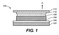
- FIG. 1 is a simplified cross-sectional depiction of an electroluminescent component 100 as can be included in analytical test strips according to embodiments of the present invention.
- Electroluminescent component 100 can serve as either an electroluminescent module (as described with respect to, for example, FIGs. 2, 3 and 4) or as an electroluminescent lamp (as described with respect to, for example, FIGs. 7, 8 and 9). However, for the sake of simplicity, electroluminescent component 100 will be referred to as an electroluminescent module hereafter.
- Electroluminescent module 100 includes a substrate layer 102, a rear electrode layer 104, an electrically-insulating layer 106 disposed over the rear electrode layer, a phosphor layer 108 disposed over electrically-insulating layer 106, and a front electrode layer 110, at least a portion of which is translucent to light emitted by phosphor layer 108, disposed over phosphor layer 108. Electroluminescent module 100 also includes an encapsulant layer 112 disposed over front electrode layer 110.
- Substrate layer 102 can be formed of any suitable substrate layer material including, for example, a polyester substrate layer material or a commercially available Melinex® ST328 (manufactured by DuPont Teijin Films) substrate layer material.
- Rear electrode layer 104 can be formed of any suitable electrically conductive material including, for example, indium tin oxide (ITO) that has been sputtered onto substrate layer 102 or gold.
- Rear electrode layer 104 can also be formed of carbon ink, silver paste or an electrically conductive polymer.
- rear electrode layer 104 can be, if desired, of any suitable pattern and can also be, for example, formed using conventional techniques such as screen-printing, laser ablation and photolithography.
- Electrically insulating layer 106 can be formed, for example, of polyester, acrylic, or epoxy-based ink materials. Electrically insulating layer 106 serves to prevent undesirable short circuits when an AC current is applied across electroluminescent module 100 to induce the emission of light from phosphor layer 108 and, subsequently, from electroluminescent module 100.
- the AC current can be applied, for example, when analytical test strips according to embodiments of the present invention are inserted into an associated analytical meter.
- Phosphor layer 108 can be formed of any suitable phosphor material known to one skilled in the art as suitable for use in an electroluminescent module or electroluminescent lamp. Examples of such phosphor materials are described in U.S. Patent No. 5,675,217 , which is hereby incorporated in full by reference. Moreover, the phosphor can, for example, include zinc chloride micro-crystals.
- Front electrode layer 110 can be formed, for example, of translucent Indium Tin Oxide (ITO) or translucent gold for example. Light emitted from electroluminescent module 100 will pass through the translucent portion of front electrode layer 110 in, for example, the direction of arrow A in FIG. 1.
- ITO Indium Tin Oxide
- Encapsulant layer 112 is configured to provide a moisture barrier and, thus, protect phosphor layer 108 from moisture-induced degradation while still providing for light to be emitted from electroluminescent module 100. Therefore, encapsulant layer 112 can be formed, for example, of any suitably transparent and moisture impermeable material. Suitable materials include epoxy resins, silicones and polyurethanes. Moreover, as described in more detail below, a wavelength modulator can be embedded or dispersed within encapsulate layer 112.
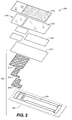
- FIG. 2 is a simplified perspective and exploded view of an analytical test strip 200 according to an embodiment of the present invention.
- Analytical test strip 200 includes a substrate layer 202 (depicted by dashed lines), an electroluminescent module 204 (including substrate layer 202 as well as a rear electrode layer 206, an electrically-insulating layer 208, a phosphor layer 210, a front electrode layer 212 and an encapsulant layer 214), and a sample chamber 216 (defined by adhesive layer 218, anti-fog layer 220, and top layer 222).
- sample chamber 216 is a capillary sample chamber.
- a fluorophore-containing photometric enzymatic reagent (not shown in FIG. 2) disposed within sample chamber 216.
- a fluorophore-containing photometric enzymatic reagent could be, for example, disposed as a layer between encapsulant layer 214 and adhesive layer 218.
- fluorophore-containing photometric enzymatic reagents employed in embodiments of the present invention include (i) enzymes specific to a predetermined analyte and fluorescent chemical reaction sequence of interest, such as glucose oxidase and horseradish peroxidase (HRP) respectively and (ii) a fluorophore, such as, for example, Amplex Red reagent (i.e., 10-acetyl-3, 7-duhydroxypehnoxazinne reagent), the proprietary and commercially available fluorophore DuoLux, coumarin, fluorescene isothio cynate (FITC), fluorescamine, and cascade blue.
- Amplex Red reagent i.e., 10-acetyl-3, 7-duhydroxypehnoxazinne reagent
- FITC fluorescamine
- fluorophore includes, but is not limited to, reagents such as Amplex Red reagent that are themselves non-fluorescent but that serve as fluorogenic probes by producing, for example, a fluorescent dye during a fluorescent chemical reaction sequence involving the fluorophore-containing photometric reagent, the analyte and light emitted from the electroluminescent module.
- fluorescent chemical reaction sequences are described further below with respect to FIGs. 3 and 4.
- the fluorophore-containing photometric enzymatic reagents can also contain, for example, a suitable buffer (such as a citrate buffer, a phosphate buffer, or a citraconate buffer) and a binder (e.g., HEC (hydroxyethly cellulose), PVA (polyvinyl alcohol), polyaniline, or CMC (carboxymethylcellulose)).
- a suitable buffer such as a citrate buffer, a phosphate buffer, or a citraconate buffer
- a binder e.g., HEC (hydroxyethly cellulose), PVA (polyvinyl alcohol), polyaniline, or CMC (carboxymethylcellulose)
- the enzyme included in the fluorophore-containing photometric enzymatic reagent is predetermined based on the analyte of interest. Therefore, other suitable enzymes include, but are nor limited to, cholesterol oxidase (for the analyte cholesterol) and amino-acid oxidase (for various amino acid analytes).
- fluorescent light emitted from phosphor layer 210 of electroluminescent module 204 propagates through front electrode layer 212 and encapsulant layer 214 to reach sample chamber 216. The fluorescent light then facilitates a fluorescent chemical reaction sequence involving the fluorophore-containing photometric enzymatic reagent and the analyte within sample chamber 216.
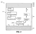
- FIG. 3 is a simplified schematic diagram of a portion of an analytical test strip 300 according to another embodiment of the present invention that includes a simplified depiction of a fluorescent chemical reaction sequence occurring within a sample chamber of the analytical test strip.
- Portion 300 includes an electroluminescent module 302, a sample chamber 304, a photodetector 306, an adhesive layer 308, an anti-fog layer 310 and a top layer 312.
- sample chamber 304 has a sample inlet 314 whereby a bodily fluid sample (e.g., a whole blood sample) is introduced into sample chamber 304.
- a bodily fluid sample e.g., a whole blood sample
- a fluorescent chemical reaction sequence occurs within sample chamber 304.
- the fluorescent chemical reaction sequence includes the following reactions involving the bodily fluid sample (and analyte therein), the fluorophore-containing photometric enzymatic reagent and light from electroluminescent module 302 (depicted by the arrows labeled A in FIG. 3):
- the fluorescence of the fluorescent molecule results in the emission emits photons proportional to the concentration of analyte in the bodily fluid sample.
- photodetector 306 that is disposed in a co-facial arrangement with respect to electroluminescent module 302.
- Photodetector 306 can be formed, for example, from cadmium sulphide and cadmium selenide in the form of a resistive electrode.
- FIG. 4 is a simplified schematic diagram of a portion of an analytical test strip 400 according to yet another exemplary embodiment of the present invention that includes a simplified depiction of a fluorescent chemical reaction sequence occurring within a sample chamber of the analytical test strip.
- Portion 400 includes an electroluminescent module 402, a sample chamber 404, a photodetector 406, an adhesive layer 408, an anti-fog layer 410 and a top layer 412.
- sample chamber 404 has a sample inlet 414 whereby a bodily fluid sample (e.g., a whole blood sample) is introduced into sample chamber 404.
- a bodily fluid sample e.g., a whole blood sample
- a fluorescent chemical reaction sequence occurs within sample chamber 404.
- the fluorescent chemical reaction sequence includes the following general reactions involving the bodily fluid sample (and analyte therein), the fluorophore-containing photometric enzymatic reagent and light from electroluminescent module 402 (depicted by the arrows labeled A in FIG. 4):
- the fluorescence of the fluorescent molecule results in the emission of photons proportional to the concentration of analyte in the bodily fluid sample.
- photodetector 406 which is disposed in a co-planar arrangement with respect to electroluminescent module 402.
- Such a co-planar arrangement can be beneficial in reducing interference with photodetector 406 by light from electroluminescent module 402.
- the photons reaching photodetector 406 are converted into a current.
- the current is translated into an analyte concentration by software within an associated analytical meter.
- light from electroluminescent modules in embodiments of the present invention serves to drive photochemistry of the fluorescent chemical reaction sequence.
- Such photochemically-driven fluorescent chemical reactions sequences are expected to provide highly precise and accurate analyte determinations via photon amplification (multiplication) behavior.
- the absorbance maximum of Amplex Red reagent is at approximately 560nm and its emission maximum is at approximately 590nm.
- a fluorescent product of Amplex Red reagent is resorufin, which has absorption and emission maxima that are sufficiently distinct from those of Amplex Red reagent such that there is expected to be little interference from auto-fluorescence for a majority of bodily fluid samples.
- Electroluminescent modules and lamps employed in embodiments of the present invention would typically emit light in the blue-green wavelength region of the visible spectrum, at approximately 490nm. However, for purposes of driving a fluorescent chemical reaction sequence, it can be advantageous to use excitation light in the orangered wavelength region that is obtained by wavelength modulation of light emitted by a phosphor layer of an electroluminescent module. Such wavelength modulation is known, in general, as a Stoke's shift.
- wavelength modulation can be used to provide light of an appropriate wavelength and intensity for use with fluorophore-containing photometric enzymatic reagents that include Amplex Red reagent.
- wavelength modulation can be achieved using, for example, fluorescein (with an absorption peak around 490nm, and an emission spectrum with a maximum around 520nm) or rhodamine with a maximum absorption around 530nm, and a broad emission spectrum up to approximately 700nm.
- Wavelength modulators such as fluorescein and rhodamine
- electroluminescent modules and electroluminescent lamps
- Wavelength modulators can be incorporated into electroluminescent modules (and electroluminescent lamps) by, for example, dispersing or embedding the wavelength modulator into an encapsulant layer or by formation as an independent layer above or below an encapsulant layer.
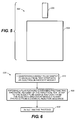
- FIG. 5 is a simplified schematic depiction of a system 500 for the determination of an analyte in a bodily fluid sample according to an exemplary embodiment of the present invention.
- System 500 includes an analytical test strip 502 and an analytical meter 504.
- Analytical test strip 502 can be any suitable analytical test strip according to embodiments of the present invention. Therefore, analytical test strip 502 has a substrate layer, an electroluminescent component (either an electroluminescent module and/or an electroluminescent lamp) disposed on the substrate layer, and a sample chamber configured for receiving a bodily fluid sample disposed above the substrate layer. Analytical meter 504 is configured for insertion of the analytical test strip therein and subsequent determination of the analyte as described elsewhere herein.
- electroluminescent component either an electroluminescent module and/or an electroluminescent lamp
- FIG. 6 is a flow diagram depicting stages in a method 600 for determining an analyte (such as glucose) in a bodily fluid sample (for example a whole blood sample) according to an exemplary embodiment of the present invention.
- Method 600 includes transferring a bodily fluid sample to a sample chamber of an analytical test strip, as set forth in step 610.
- the analytical test strip to which the bodily fluid sample is transferred includes a substrate layer, an electroluminescent module disposed on the substrate layer and in optical communication with the sample chamber, a fluorophore-containing photometric enzymatic reagent disposed within the sample chamber.
- the electroluminescent module of the analytical test strip is configured to emit light that facilitates a fluorescent chemical reaction sequence involving the fluorophore-containing photometric enzymatic reagent and the analyte.
- Method 600 also includes, at step 620, exposing the fluorophore-containing photometric enzymatic reagent to the bodily fluid sample and to light emitted from the electroluminescent module such that photons are emitted from the fluorophore-containing photometric enzymatic reagent via a fluorescent chemical reaction sequence. The photons are then detected with a photodetector, as set forth in step 630.
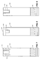
- FIG. 7 is a simplified top view of an analytical test strip 700 with an electroluminescent lamp according to an exemplary embodiment of the present invention.
- Analytical test strip 700 includes a substrate layer (not shown), an electroluminescent lamp 702 disposed on the substrate layer, a sample chamber 704 configured for receiving the bodily fluid sample disposed above the substrate layer and an enzymatic reagent (not depicted) disposed within the sample chamber.
- Analytical test strip 700 also includes electrical contacts 706 for conducting power and signals to and from various components of the analytical test strip.
- Electroluminescent lamp 702 is configured to emit light, the light being visible to a user of the analytical test strip and providing the user with spatial awareness of the analytical test strip.
- electroluminescent lamp 702 is configured to emit light that appears as two directional arrows to a user, with the directional arrows indicating a bodily fluid sample application area of the analytical test strip.
- FIG. 8 is a simplified top view of an analytical test strip 800 with an electroluminescent lamp according to another exemplary embodiment of the present invention.
- Analytical test strip 800 includes a substrate layer (not shown), an electroluminescent lamp 802 disposed on the substrate layer, a sample chamber 804 configured for receiving the bodily fluid sample disposed above the substrate layer and an enzymatic reagent (not depicted) disposed within the sample chamber.
- Analytical test strip 800 also includes electrical contacts 806 for conducting power and signals to and from various components of the analytical test strip.
- Electroluminescent lamp 802 is configured to emit light, the light being visible to a user of the analytical test strip and providing the user with spatial awareness of the analytical test strip.
- electroluminescent lamp 802 is configured to emit light in a continuous band along a distal end 808 of the analytical test strip where the bodily fluid sample is to be applied.
- FIG. 9 is a simplified top view of an analytical test strip 900 with an electroluminescent lamp according to yet another exemplary embodiment of the present invention.
- Analytical test strip 900 includes a substrate layer (not shown), an electroluminescent lamp 902 disposed on the substrate layer, a sample chamber 904 configured for receiving the bodily fluid sample disposed above the substrate layer and an enzymatic reagent (not depicted) disposed within the sample chamber.
- Analytical test strip 900 also includes electrical contacts 906 for conducting power and signals to and from various components of the analytical test strip.
- Electroluminescent lamp 902 is configured to emit light, the light being visible to a user of the analytical test strip and providing the user with spatial awareness of the analytical test strip.
- electroluminescent lamp 902 is configured to emit light along a periphery of the sample chamber (for example, a capillary sample chamber) to facilitate visual determination of complete capillary sample fill by a bodily fluid sample.
- analytical test strips with electroluminescent lamps according to embodiments of the present invention can employ and suitable features and characteristics of analytical test strips with electroluminescent modules and systems according to embodiments of the present invention.
- analytical test strips with electroluminescent lamps according to embodiments of the present invention can be electrochemical-based analytical test strips or photochemical-based analytical test strips.
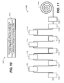
- FIG. 10 is a flow diagram depicting stages in a method 1000 for manufacturing an analytical test strip for determination of an analyte (such as glucose) in a bodily fluid sample (for example a whole blood sample) according to an exemplary embodiment of the present invention.
- FIG. 11 is a simplified depiction of a continuous web printing apparatus 1100 as can be employed in method 1000 and other method embodiments of the present invention.
- method 1000 includes at step 1010, sequentially applying to a substrate layer, a:
- Method 1000 can be accomplished using screen-printing technology, flat-bed printing, continuous web-based printing technology or any combination thereof.
- continuous web-based printing technology can be especially beneficial in terms of printing yield and alignment.
- continuous web printing apparatus 1100 can be employed with a substrate 1104 to conduct method 1000.
- an optional preconditioning station 1106, a rear electrode layer print station 1108, a first dryer 1110, an electrically-insulating layer print station 1112, a second dryer 1114, a phosphor layer print station 1116, a third dryer 1118, a translucent front electrode layer print station 1120, a fourth dryer 1122 and an encapsulant layer print station 1124 can be employed to manufacture analytical tests strips.
- a system for the determination of an analyte in a bodily fluid sample comprising an analytical test strip that includes: a substrate layer; an electroluminescent component disposed on the substrate layer; a sample chamber configured for receiving a bodily fluid sample disposed above the substrate layer; and an analytical meter configured for insertion of the analytical test strip therein and subsequent determination of an analyte in the bodily fluid sample,
- the electroluminescent component is an electroluminescent module and wherein the analytical test strip also includes a fluorophore-containing photometric enzymatic reagent disposed within the sample chamber, and wherein the electroluminescent module is in optical communication with the sample chamber, and wherein the electroluminescent module is configured to emit light that facilitates a fluorescent chemical reaction sequence between the fluorophore-containing photometric enzymatic reagent and the analyte.
- the analytical test strip further includes a photodetector disposed above the substrate layer, and wherein the photodetector is positioned to detect photons emitted from the fluorophore-containing photometric enzymatic reagent subsequent to exposure of the fluorophore-containing photometric enzymatic reagent to the bodily fluid sample and to light from the electroluminescent module.
- the photodetector includes a photo-resistor electrode formed from one of cadmium sulphide and cadmium selenide.
- fluorophore-containing photometric enzymatic reagent includes glucose oxidase, horseradish peroxidase and Amplex Red reagent.
- the electroluminescent module is an electroluminescent lamp
- the electroluminescent lamp is configured to emit light, the light being visible to a user of the analytical test strip and providing the user with spatial awareness of the analytical test strip.
- the electroluminescent component includes: a rear electrode layer; an electrically-insulating layer disposed over the rear electrode layer; a phosphor layer disposed over the electrically insulating layer; and a front electrode layer, at least a portion of which is translucent, disposed over the phosphor layer.
- electroluminescent component further includes an encapsulant layer.
- the electroluminescent module further includes a wavelength modulation layer configured to shift the wavelength of light emitted by the phosphor layer.
- wavelength modulation layer includes fluorescein.
- the wavelength modulation layer includes rhodamine.
- a method for the determination of an analyte in a bodily fluid sample comprising: transferring a bodily fluid sample to a sample chamber of an analytical test strip, the analytical test strip including: a substrate layer; an electroluminescent module disposed on the substrate layer and in optical communication with the sample chamber; a fluorophore-containing photometric enzymatic reagent disposed within the sample chamber; and the sample chamber, and wherein the electroluminescent module is configured to emit light that facilitates a fluorescent chemical reaction sequence involving the fluorophore-containing photometric enzymatic reagent and the analyte; exposing the fluorophore-containing photometric enzymatic reagent to the bodily fluid sample and to light emitted from the electroluminescent module such that photons are emitted from the fluorophore-containing photometric enzymatic reagent via a fluorescent chemical reaction sequence; and detecting the photons with a photodetector.
- the electroluminescent module includes: a rear electrode layer; an electrically-insulating layer disposed over the rear electrode layer; a phosphor layer disposed over the electrically insulating layer; and a front electrode layer, at least a portion of which is translucent, disposed over the phosphor layer.
- a method wherein the electroluminescent module further includes an encapsulant layer.
- the electroluminescent module further includes a wavelength modulation layer configured to shift the wavelength of light emitted by the phosphor layer.
- wavelength modulation layer includes fluorescein
- wavelength modulation layer includes rhodamine
- wavelength modulation layer shifts the wavelength of light emitted by the phosphor layer via a Stoke's shift.
- the analytical test strip further including a photodetector disposed above the substrate layer, and wherein the photodetector is positioned to detect, during the detecting step, photons emitted from the fluorophore-containing photometric enzymatic reagent subsequent to exposure of the fluorophore-containing photometric enzymatic reagent to the bodily fluid sample and to light from the electroluminescent module.
- fluorophore-containing photometric enzymatic reagent includes glucose oxidase, horseradish peroxidase and Amplex Red reagent.
- a method for manufacturing an analytical test strip with an electroluminescent component comprising: applying, in a sequential manner, to a substrate layer of an analytical test strip: a rear electrode layer; an electrically-insulating layer disposed over the rear electrode layer; a phosphor layer disposed over the electrically insulating layer; and a front electrode layer, at least a portion of which is translucent, disposed over the phosphor layer, thereby forming an electroluminescent component of the analytical test strip.
- the aforementioned method wherein the applying step further applies an encapsulant layer disposed over the front electrode layer.
- the electroluminescent component is an electroluminescent module configured to emit light that facilitates a fluorescent chemical reaction sequence involving a fluorophore-containing photometric enzymatic reagent of the analytical test strip and the analyte.
- the electroluminescent component is an electroluminescent lamp configured to emit light that provides spatial awareness to a user.
Abstract
Description
- The present invention relates, in general, to analytical devices and, in particular, to analytical test strips and related systems and methods.
- The determination (e.g., detection and/or concentration measurement) of an analyte (such as glucose) in a bodily fluid sample is of particular interest in the medical field. For example, it can be desirable to determine glucose, cholesterol, acetaminophen and/or HbA1c concentrations in a sample of a bodily fluid such as urine, blood or interstitial fluid. Such determinations can be achieved using analytical test strips based on, for example, photometric or electrochemical techniques, along with an associated meter.
- Typical photometric analytical test strips employ a fluid sample application zone (e.g., a sample chamber), a photometric enzymatic reagent that engages in a photometric reaction (for example a color-inducing reaction) with an analyte of interest, and a detector of an associated meter to determine the concentration of the analyte. For example, a photometric analytical test strip for the determination of glucose concentration in a blood sample can employ a photometric enzymatic reagent that includes the enzyme glucose oxidase and a chromophore (such as 3-methyl-2-benzothiazolinone hydrazone hydrocholoride [MBTH] and 3-dimethyaminobenzoic acid [DMAB]). Further details of conventional photometric analytical test strips are included in
U.S. Patent No.s 5,753,452 ,6,168,957 ,6,555,061 ,5,426,032 and6,821,482 , each of which is hereby incorporated in full by reference. - A better understanding of the features and advantages of the present invention will be obtained by reference to the following detailed description that sets forth illustrative embodiments, in which the principles of the invention are utilized, and the accompanying drawings, of which:
- FIG. 1 is a simplified cross-sectional depiction of an electroluminescent component as can be included in analytical test strips according to embodiments of the present invention;
- FIG. 2 is a perspective exploded view of an analytical test strip including an electroluminescent module according to an exemplary embodiment of the present invention;
- FIG. 3 is a simplified schematic diagram of a portion of an analytical test strip according to another embodiment of the present invention that includes a simplified depiction of a fluorescent chemical reaction sequence occurring within a sample chamber of the analytical test strip;
- FIG. 4 is a simplified schematic diagram of a portion of an analytical test strip according to yet another exemplary embodiment of the present invention that includes a simplified depiction of a fluorescent chemical reaction sequence occurring within a sample chamber of the analytical test strip;
- FIG. 5 is a simplified schematic depiction of a system for the determination of an analyte in a bodily fluid sample according to an exemplary embodiment of the present invention;
- FIG. 6 is a flow diagram depicting stages in a process for determining an analyte in a bodily fluid sample according to an exemplary embodiment of the present invention;
- FIG. 7 is a simplified top view of an analytical test strip with an electroluminescent lamp according to an exemplary embodiment of the present invention;
- FIG. 8 is a simplified top view of an analytical test strip with an electroluminescent lamp according to another exemplary embodiment of the present invention;
- FIG. 9 is a simplified top view of an analytical test strip with an electroluminescent lamp according to yet another exemplary embodiment of the present invention;
- FIG. 10 is a flow diagram depicting stages in a process for manufacturing an analytical test strip for determination of an analyte in a bodily fluid sample according to an exemplary embodiment of the present invention; and
- FIG. 11 is a simplified depiction of a continuous web printing apparatus as can be employed in embodiments of the present invention.
- An analytical test strip for the determination of an analyte (such as glucose) in a bodily fluid sample (e.g., a whole blood sample) according to various embodiments of the present invention includes a substrate layer, an electroluminescent module disposed on the substrate layer, a sample chamber (such as a capillary sample chamber) configured for receiving the bodily fluid sample disposed above the substrate layer and a fluorophore-containing photometric enzymatic reagent disposed within the sample chamber. In addition, the electroluminescent module is in optical communication with the sample chamber and is configured to emit light that facilitates a fluorescent chemical reaction sequence between the fluorophore-containing photometric enzymatic reagent and the analyte. Further details of such analytical test strips are described below and, in particular, with respect to FIGs. 1, 2, 3 and 4.
- An analytical test strip for the determination of an analyte (such as glucose) in a bodily fluid sample (for example, a whole blood sample) according to other embodiments of the present invention include a substrate layer, an electroluminescent lamp disposed on the substrate layer, a sample chamber configured for receiving the bodily fluid sample disposed above the substrate layer; and an enzymatic reagent disposed within the sample chamber. Moreover, the electroluminescent lamp is configured to emit light, the light being visible to a user of the analytical test strip and providing the user with spatial awareness of the analytical test strip. Further details of such analytical test strips are described below and, in particular, with respect to FIGs. 1, 7, 8 and 9.
- FIG. 1 is a simplified cross-sectional depiction of an
electroluminescent component 100 as can be included in analytical test strips according to embodiments of the present invention.Electroluminescent component 100 can serve as either an electroluminescent module (as described with respect to, for example, FIGs. 2, 3 and 4) or as an electroluminescent lamp (as described with respect to, for example, FIGs. 7, 8 and 9). However, for the sake of simplicity,electroluminescent component 100 will be referred to as an electroluminescent module hereafter. -
Electroluminescent module 100 includes asubstrate layer 102, arear electrode layer 104, an electrically-insulatinglayer 106 disposed over the rear electrode layer, aphosphor layer 108 disposed over electrically-insulatinglayer 106, and afront electrode layer 110, at least a portion of which is translucent to light emitted byphosphor layer 108, disposed overphosphor layer 108.Electroluminescent module 100 also includes anencapsulant layer 112 disposed overfront electrode layer 110. -
Substrate layer 102 can be formed of any suitable substrate layer material including, for example, a polyester substrate layer material or a commercially available Melinex® ST328 (manufactured by DuPont Teijin Films) substrate layer material. -
Rear electrode layer 104 can be formed of any suitable electrically conductive material including, for example, indium tin oxide (ITO) that has been sputtered ontosubstrate layer 102 or gold.Rear electrode layer 104 can also be formed of carbon ink, silver paste or an electrically conductive polymer. In addition,rear electrode layer 104 can be, if desired, of any suitable pattern and can also be, for example, formed using conventional techniques such as screen-printing, laser ablation and photolithography. - Electrically insulating
layer 106 can be formed, for example, of polyester, acrylic, or epoxy-based ink materials. Electrically insulatinglayer 106 serves to prevent undesirable short circuits when an AC current is applied acrosselectroluminescent module 100 to induce the emission of light fromphosphor layer 108 and, subsequently, fromelectroluminescent module 100. The AC current can be applied, for example, when analytical test strips according to embodiments of the present invention are inserted into an associated analytical meter. -
Phosphor layer 108 can be formed of any suitable phosphor material known to one skilled in the art as suitable for use in an electroluminescent module or electroluminescent lamp. Examples of such phosphor materials are described inU.S. Patent No. 5,675,217 , which is hereby incorporated in full by reference. Moreover, the phosphor can, for example, include zinc chloride micro-crystals. -
Front electrode layer 110 can be formed, for example, of translucent Indium Tin Oxide (ITO) or translucent gold for example. Light emitted fromelectroluminescent module 100 will pass through the translucent portion offront electrode layer 110 in, for example, the direction of arrow A in FIG. 1. -
Encapsulant layer 112 is configured to provide a moisture barrier and, thus, protectphosphor layer 108 from moisture-induced degradation while still providing for light to be emitted fromelectroluminescent module 100. Therefore,encapsulant layer 112 can be formed, for example, of any suitably transparent and moisture impermeable material. Suitable materials include epoxy resins, silicones and polyurethanes. Moreover, as described in more detail below, a wavelength modulator can be embedded or dispersed withinencapsulate layer 112. - FIG. 2 is a simplified perspective and exploded view of an
analytical test strip 200 according to an embodiment of the present invention.Analytical test strip 200 includes a substrate layer 202 (depicted by dashed lines), an electroluminescent module 204 (includingsubstrate layer 202 as well as arear electrode layer 206, an electrically-insulating layer 208, aphosphor layer 210, afront electrode layer 212 and an encapsulant layer 214), and a sample chamber 216 (defined byadhesive layer 218,anti-fog layer 220, and top layer 222). In the embodiment of FIG. 2,sample chamber 216 is a capillary sample chamber. - Also included in
analytical test strip 200 is a fluorophore-containing photometric enzymatic reagent (not shown in FIG. 2) disposed withinsample chamber 216. Such a fluorophore-containing photometric enzymatic reagent could be, for example, disposed as a layer betweenencapsulant layer 214 andadhesive layer 218. - In general, fluorophore-containing photometric enzymatic reagents employed in embodiments of the present invention include (i) enzymes specific to a predetermined analyte and fluorescent chemical reaction sequence of interest, such as glucose oxidase and horseradish peroxidase (HRP) respectively and (ii) a fluorophore, such as, for example, Amplex Red reagent (i.e., 10-acetyl-3, 7-duhydroxypehnoxazinne reagent), the proprietary and commercially available fluorophore DuoLux, coumarin, fluorescene isothio cynate (FITC), fluorescamine, and cascade blue.
- It should be noted that the term "fluorophore" includes, but is not limited to, reagents such as Amplex Red reagent that are themselves non-fluorescent but that serve as fluorogenic probes by producing, for example, a fluorescent dye during a fluorescent chemical reaction sequence involving the fluorophore-containing photometric reagent, the analyte and light emitted from the electroluminescent module. Such fluorescent chemical reaction sequences are described further below with respect to FIGs. 3 and 4.
- The fluorophore-containing photometric enzymatic reagents can also contain, for example, a suitable buffer (such as a citrate buffer, a phosphate buffer, or a citraconate buffer) and a binder (e.g., HEC (hydroxyethly cellulose), PVA (polyvinyl alcohol), polyaniline, or CMC (carboxymethylcellulose)). By means of comparison and background, typical components of conventional photometric enzymatic reagents are described in, for example,
U.S. Patent No. 5,453,360 , which is hereby incorporated in full by reference. - As mentioned above, the enzyme included in the fluorophore-containing photometric enzymatic reagent is predetermined based on the analyte of interest. Therefore, other suitable enzymes include, but are nor limited to, cholesterol oxidase (for the analyte cholesterol) and amino-acid oxidase (for various amino acid analytes). In the embodiment of FIG. 2, fluorescent light emitted from
phosphor layer 210 ofelectroluminescent module 204 propagates throughfront electrode layer 212 andencapsulant layer 214 to reachsample chamber 216. The fluorescent light then facilitates a fluorescent chemical reaction sequence involving the fluorophore-containing photometric enzymatic reagent and the analyte withinsample chamber 216. - FIG. 3 is a simplified schematic diagram of a portion of an
analytical test strip 300 according to another embodiment of the present invention that includes a simplified depiction of a fluorescent chemical reaction sequence occurring within a sample chamber of the analytical test strip.Portion 300 includes anelectroluminescent module 302, asample chamber 304, aphotodetector 306, anadhesive layer 308, ananti-fog layer 310 and atop layer 312. Moreover,sample chamber 304 has asample inlet 314 whereby a bodily fluid sample (e.g., a whole blood sample) is introduced intosample chamber 304. - A fluorescent chemical reaction sequence (as previously described) occurs within
sample chamber 304. In the embodiment of FIG. 3, the fluorescent chemical reaction sequence includes the following reactions involving the bodily fluid sample (and analyte therein), the fluorophore-containing photometric enzymatic reagent and light from electroluminescent module 302 (depicted by the arrows labeled A in FIG. 3): - (1) an analyte (e.g., glucose) + enzyme (e.g., glucose oxidase) react to produce a product (e.g., gluconic acid) and H2O2;
- (2) H2O2 (from (1) above) reacts with a fluorophore (e.g., Amplex Red reagent) and horseradish peroxidase (HRP), under the influence of light from
electroluminescent module 302, to produce a fluorescent molecule (e.g., resorufin); and - (3) the fluorescent molecule undergoes fluorophore excitation, resulting in photon emission (arrow B in FIG. 3)
- In the embodiment of FIG. 3, the fluorescence of the fluorescent molecule (e.g., resorufin) results in the emission emits photons proportional to the concentration of analyte in the bodily fluid sample. These photons are then detected by
photodetector 306, that is disposed in a co-facial arrangement with respect toelectroluminescent module 302.Photodetector 306 can be formed, for example, from cadmium sulphide and cadmium selenide in the form of a resistive electrode. - FIG. 4 is a simplified schematic diagram of a portion of an
analytical test strip 400 according to yet another exemplary embodiment of the present invention that includes a simplified depiction of a fluorescent chemical reaction sequence occurring within a sample chamber of the analytical test strip.Portion 400 includes anelectroluminescent module 402, asample chamber 404, aphotodetector 406, an adhesive layer 408, an anti-fog layer 410 and a top layer 412. Moreover,sample chamber 404 has asample inlet 414 whereby a bodily fluid sample (e.g., a whole blood sample) is introduced intosample chamber 404. - A fluorescent chemical reaction sequence (as previously described) occurs within
sample chamber 404. In the embodiment of FIG. 4, the fluorescent chemical reaction sequence includes the following general reactions involving the bodily fluid sample (and analyte therein), the fluorophore-containing photometric enzymatic reagent and light from electroluminescent module 402 (depicted by the arrows labeled A in FIG. 4): - (1) an analyte + an analyte-specific enzyme react to produce a product + H2O2;
- (2) H2O2 (from (1) immediately above) reacts with a fluorophore and HRP, under the influence of light from
electroluminescent module 402, to produce a fluorescent molecule (not shown in FIG. 4); and - (3) the fluorescent molecule undergoes fluorophore excitation, resulting in photon emission (arrows D in FIG. 4)
- In the embodiment of FIG. 4, the fluorescence of the fluorescent molecule results in the emission of photons proportional to the concentration of analyte in the bodily fluid sample. These photons are then detected by
photodetector 406, which is disposed in a co-planar arrangement with respect toelectroluminescent module 402. Such a co-planar arrangement can be beneficial in reducing interference withphotodetector 406 by light fromelectroluminescent module 402. Thephotons reaching photodetector 406 are converted into a current. The current is translated into an analyte concentration by software within an associated analytical meter. - Once apprised of the present disclosure, one skilled in the art will recognize that light from electroluminescent modules in embodiments of the present invention serves to drive photochemistry of the fluorescent chemical reaction sequence. Such photochemically-driven fluorescent chemical reactions sequences are expected to provide highly precise and accurate analyte determinations via photon amplification (multiplication) behavior.
- It should be noted that the absorbance maximum of Amplex Red reagent is at approximately 560nm and its emission maximum is at approximately 590nm. In certain embodiments of the present invention, a fluorescent product of Amplex Red reagent is resorufin, which has absorption and emission maxima that are sufficiently distinct from those of Amplex Red reagent such that there is expected to be little interference from auto-fluorescence for a majority of bodily fluid samples.
- Electroluminescent modules and lamps employed in embodiments of the present invention would typically emit light in the blue-green wavelength region of the visible spectrum, at approximately 490nm. However, for purposes of driving a fluorescent chemical reaction sequence, it can be advantageous to use excitation light in the orangered wavelength region that is obtained by wavelength modulation of light emitted by a phosphor layer of an electroluminescent module. Such wavelength modulation is known, in general, as a Stoke's shift.
- For example, since the absorbance maximum of Amplex Red reagent is approximately 560nm, wavelength modulation can be used to provide light of an appropriate wavelength and intensity for use with fluorophore-containing photometric enzymatic reagents that include Amplex Red reagent. Such wavelength modulation can be achieved using, for example, fluorescein (with an absorption peak around 490nm, and an emission spectrum with a maximum around 520nm) or rhodamine with a maximum absorption around 530nm, and a broad emission spectrum up to approximately 700nm.
- Wavelength modulators (such as fluorescein and rhodamine) can be incorporated into electroluminescent modules (and electroluminescent lamps) by, for example, dispersing or embedding the wavelength modulator into an encapsulant layer or by formation as an independent layer above or below an encapsulant layer.
- FIG. 5 is a simplified schematic depiction of a
system 500 for the determination of an analyte in a bodily fluid sample according to an exemplary embodiment of the present invention.System 500 includes ananalytical test strip 502 and ananalytical meter 504. -
Analytical test strip 502 can be any suitable analytical test strip according to embodiments of the present invention. Therefore,analytical test strip 502 has a substrate layer, an electroluminescent component (either an electroluminescent module and/or an electroluminescent lamp) disposed on the substrate layer, and a sample chamber configured for receiving a bodily fluid sample disposed above the substrate layer.Analytical meter 504 is configured for insertion of the analytical test strip therein and subsequent determination of the analyte as described elsewhere herein. - FIG. 6 is a flow diagram depicting stages in a
method 600 for determining an analyte (such as glucose) in a bodily fluid sample (for example a whole blood sample) according to an exemplary embodiment of the present invention.Method 600 includes transferring a bodily fluid sample to a sample chamber of an analytical test strip, as set forth instep 610. - The analytical test strip to which the bodily fluid sample is transferred includes a substrate layer, an electroluminescent module disposed on the substrate layer and in optical communication with the sample chamber, a fluorophore-containing photometric enzymatic reagent disposed within the sample chamber. Moreover, the electroluminescent module of the analytical test strip is configured to emit light that facilitates a fluorescent chemical reaction sequence involving the fluorophore-containing photometric enzymatic reagent and the analyte.
-
Method 600 also includes, atstep 620, exposing the fluorophore-containing photometric enzymatic reagent to the bodily fluid sample and to light emitted from the electroluminescent module such that photons are emitted from the fluorophore-containing photometric enzymatic reagent via a fluorescent chemical reaction sequence. The photons are then detected with a photodetector, as set forth instep 630. - Once apprised of the present disclosure, one skilled in the art will recognize that methods for the determination of an analyte according to embodiments of the present invention can include steps that utilize any of the characteristics and features of analytical test strips and systems according to embodiments of the present invention.
- FIG. 7 is a simplified top view of an
analytical test strip 700 with an electroluminescent lamp according to an exemplary embodiment of the present invention.Analytical test strip 700 includes a substrate layer (not shown), anelectroluminescent lamp 702 disposed on the substrate layer, asample chamber 704 configured for receiving the bodily fluid sample disposed above the substrate layer and an enzymatic reagent (not depicted) disposed within the sample chamber.Analytical test strip 700 also includeselectrical contacts 706 for conducting power and signals to and from various components of the analytical test strip. -
Electroluminescent lamp 702 is configured to emit light, the light being visible to a user of the analytical test strip and providing the user with spatial awareness of the analytical test strip. In particular, in the embodiment of FIG. 7,electroluminescent lamp 702 is configured to emit light that appears as two directional arrows to a user, with the directional arrows indicating a bodily fluid sample application area of the analytical test strip. - FIG. 8 is a simplified top view of an
analytical test strip 800 with an electroluminescent lamp according to another exemplary embodiment of the present invention.Analytical test strip 800 includes a substrate layer (not shown), anelectroluminescent lamp 802 disposed on the substrate layer, asample chamber 804 configured for receiving the bodily fluid sample disposed above the substrate layer and an enzymatic reagent (not depicted) disposed within the sample chamber.Analytical test strip 800 also includeselectrical contacts 806 for conducting power and signals to and from various components of the analytical test strip. -
Electroluminescent lamp 802 is configured to emit light, the light being visible to a user of the analytical test strip and providing the user with spatial awareness of the analytical test strip. In particular, in the embodiment of FIG. 8,electroluminescent lamp 802 is configured to emit light in a continuous band along adistal end 808 of the analytical test strip where the bodily fluid sample is to be applied. - FIG. 9 is a simplified top view of an
analytical test strip 900 with an electroluminescent lamp according to yet another exemplary embodiment of the present invention.Analytical test strip 900 includes a substrate layer (not shown), anelectroluminescent lamp 902 disposed on the substrate layer, asample chamber 904 configured for receiving the bodily fluid sample disposed above the substrate layer and an enzymatic reagent (not depicted) disposed within the sample chamber.Analytical test strip 900 also includeselectrical contacts 906 for conducting power and signals to and from various components of the analytical test strip. -
Electroluminescent lamp 902 is configured to emit light, the light being visible to a user of the analytical test strip and providing the user with spatial awareness of the analytical test strip. In particular, in the embodiment of FIG. 9,electroluminescent lamp 902 is configured to emit light along a periphery of the sample chamber (for example, a capillary sample chamber) to facilitate visual determination of complete capillary sample fill by a bodily fluid sample. - Once apprised of the present disclosure, one skilled in the art will recognize that analytical test strips with electroluminescent lamps according to embodiments of the present invention can employ and suitable features and characteristics of analytical test strips with electroluminescent modules and systems according to embodiments of the present invention. Moreover, analytical test strips with electroluminescent lamps according to embodiments of the present invention can be electrochemical-based analytical test strips or photochemical-based analytical test strips.
- FIG. 10 is a flow diagram depicting stages in a
method 1000 for manufacturing an analytical test strip for determination of an analyte (such as glucose) in a bodily fluid sample (for example a whole blood sample) according to an exemplary embodiment of the present invention. FIG. 11 is a simplified depiction of a continuousweb printing apparatus 1100 as can be employed inmethod 1000 and other method embodiments of the present invention. - Referring to FIG. 10,
method 1000 includes atstep 1010, sequentially applying to a substrate layer, a: - (i) rear electrode layer,
- (ii) an electrically-insulating layer disposed over the rear electrode layer,
- (iii) a phosphor layer disposed over the electrically insulating layer, and
- (iv) a front electrode layer, at least a portion of which is translucent, disposed over the phosphor layer.
The sequential application is accomplished such that it forms an electroluminescent component (either an electroluminescent lamp or an electroluminescent module as described herein with respect to various embodiments of the present invention) of the analytical test strip. If desired, any of the sequential applications can be followed by a drying step prior to the next sequential application (i.e., an intermittent drying step). Moreover, an encapsulant layer can also be sequentially applied. -
Method 1000 can be accomplished using screen-printing technology, flat-bed printing, continuous web-based printing technology or any combination thereof. In this respect, continuous web-based printing technology can be especially beneficial in terms of printing yield and alignment. For example, continuousweb printing apparatus 1100 can be employed with asubstrate 1104 to conductmethod 1000. In this circumstance, anoptional preconditioning station 1106, a rear electrodelayer print station 1108, afirst dryer 1110, an electrically-insulatinglayer print station 1112, asecond dryer 1114, a phosphorlayer print station 1116, athird dryer 1118, a translucent front electrodelayer print station 1120, afourth dryer 1122 and an encapsulantlayer print station 1124 can be employed to manufacture analytical tests strips. - Once apprised of the present disclosure, one skilled in the art will recognize that methods for manufacturing analytical test strips according to the present invention can be used to manufacture analytical test strips according to the present invention including, but not limited to, analytical test strips as depicted in FIGs. 2, 3, 4, 7, 8 and 9.
- A system for the determination of an analyte in a bodily fluid sample, the system comprising an analytical test strip that includes: a substrate layer; an electroluminescent component disposed on the substrate layer; a sample chamber configured for receiving a bodily fluid sample disposed above the substrate layer; and an analytical meter configured for insertion of the analytical test strip therein and subsequent determination of an analyte in the bodily fluid sample,
- The aforementioned system wherein the electroluminescent component is an electroluminescent module and wherein the analytical test strip also includes a fluorophore-containing photometric enzymatic reagent disposed within the sample chamber, and wherein the electroluminescent module is in optical communication with the sample chamber, and wherein the electroluminescent module is configured to emit light that facilitates a fluorescent chemical reaction sequence between the fluorophore-containing photometric enzymatic reagent and the analyte.
- The aforementioned system wherein the analytical test strip further includes a photodetector disposed above the substrate layer, and wherein the photodetector is positioned to detect photons emitted from the fluorophore-containing photometric enzymatic reagent subsequent to exposure of the fluorophore-containing photometric enzymatic reagent to the bodily fluid sample and to light from the electroluminescent module.
- The aforementioned system wherein the photodetector includes a photo-resistor electrode formed from one of cadmium sulphide and cadmium selenide.
- The aforementioned system wherein the fluorophore-containing photometric enzymatic reagent includes glucose oxidase, horseradish peroxidase and Amplex Red reagent.
- The aforementioned system wherein the fluorescent chemical reaction sequence produces resorufin such that fluorescence of the resorufin emits photons proportional to the concentration of analyte in the bodily fluid sample.
- The aforementioned system wherein the electroluminescent module is an electroluminescent lamp, and wherein the electroluminescent lamp is configured to emit light, the light being visible to a user of the analytical test strip and providing the user with spatial awareness of the analytical test strip.
- The aforementioned system wherein the analytical test strip and analytical meter are configured for the determination of glucose in a whole blood sample.
- The aforementioned system wherein the electroluminescent component includes: a rear electrode layer; an electrically-insulating layer disposed over the rear electrode layer; a phosphor layer disposed over the electrically insulating layer; and a front electrode layer, at least a portion of which is translucent, disposed over the phosphor layer.
- The aforementioned system wherein the electroluminescent component further includes an encapsulant layer.
- The aforementioned system wherein the electroluminescent module further includes a wavelength modulation layer configured to shift the wavelength of light emitted by the phosphor layer.
- The aforementioned system wherein the wavelength modulation layer includes fluorescein.
- The aforementioned system wherein the wavelength modulation layer includes rhodamine.
- The aforementioned system wherein the wavelength modulation layer shifts the wavelength of light emitted by the phosphor layer via a Stoke's shift.
- A method for the determination of an analyte in a bodily fluid sample, the method comprising: transferring a bodily fluid sample to a sample chamber of an analytical test strip, the analytical test strip including: a substrate layer; an electroluminescent module disposed on the substrate layer and in optical communication with the sample chamber; a fluorophore-containing photometric enzymatic reagent disposed within the sample chamber; and the sample chamber, and wherein the electroluminescent module is configured to emit light that facilitates a fluorescent chemical reaction sequence involving the fluorophore-containing photometric enzymatic reagent and the analyte; exposing the fluorophore-containing photometric enzymatic reagent to the bodily fluid sample and to light emitted from the electroluminescent module such that photons are emitted from the fluorophore-containing photometric enzymatic reagent via a fluorescent chemical reaction sequence; and detecting the photons with a photodetector.
- The method wherein the electroluminescent module includes: a rear electrode layer; an electrically-insulating layer disposed over the rear electrode layer; a phosphor layer disposed over the electrically insulating layer; and a front electrode layer, at least a portion of which is translucent, disposed over the phosphor layer.
- A method wherein the electroluminescent module further includes an encapsulant layer.
- A method wherein the electroluminescent module further includes a wavelength modulation layer configured to shift the wavelength of light emitted by the phosphor layer.
- A method wherein the wavelength modulation layer includes fluorescein.
- A method wherein the wavelength modulation layer includes rhodamine.
- A method wherein the wavelength modulation layer shifts the wavelength of light emitted by the phosphor layer via a Stoke's shift.
- The aforementioned method wherein the analytical test strip further including a photodetector disposed above the substrate layer, and wherein the photodetector is positioned to detect, during the detecting step, photons emitted from the fluorophore-containing photometric enzymatic reagent subsequent to exposure of the fluorophore-containing photometric enzymatic reagent to the bodily fluid sample and to light from the electroluminescent module.
- The aforementioned method wherein the photodetector is disposed coplanar with the electroluminescent module.
- The aforementioned method wherein the photodetector is disposed co-facial with the electroluminescent module.
- The aforementioned method wherein the fluorophore-containing photometric enzymatic reagent includes glucose oxidase, horseradish peroxidase and Amplex Red reagent.
- The aforementioned method wherein the fluorescent chemical reaction sequence produces resorufin such that fluorescence of the resorufin emits photons proportional to the concentration of analyte in the bodily fluid sample.
- A method for manufacturing an analytical test strip with an electroluminescent component, the method comprising: applying, in a sequential manner, to a substrate layer of an analytical test strip: a rear electrode layer; an electrically-insulating layer disposed over the rear electrode layer; a phosphor layer disposed over the electrically insulating layer; and a front electrode layer, at least a portion of which is translucent, disposed over the phosphor layer, thereby forming an electroluminescent component of the analytical test strip.
- The aforementioned method wherein the applying step further applies an encapsulant layer disposed over the front electrode layer.
- The aforementioned method wherein the encapsulant layer includes a wavelength modulator.
- The aforementioned method wherein the applying step is conducted using continuous web-printing techniques.
- The aforementioned method wherein the applying step is conducted using flat-bed printing techniques.
- The aforementioned method wherein the applying step is conducted using a combination of flat-bed and web-based continuous printing technologies.
- The aforementioned method wherein a drying occurs intermittently during the applying step.
- The aforementioned method wherein the electroluminescent component is an electroluminescent module configured to emit light that facilitates a fluorescent chemical reaction sequence involving a fluorophore-containing photometric enzymatic reagent of the analytical test strip and the analyte.
- The aforementioned method wherein the electroluminescent component is an electroluminescent lamp configured to emit light that provides spatial awareness to a user.
- It should be understood that various alternatives to the embodiments of the invention described herein may be employed in practicing the invention. It is intended that the following claims define the scope of the invention and that structures and methods within the scope of these claims and their equivalents be covered thereby.
Claims (10)
- An analytical test strip for the determination of an analyte in a bodily fluid sample, the analytical test strip comprising:a substrate layer;an electroluminescent lamp disposed on the substrate layer;a sample chamber configured for receiving the bodily fluid sample disposed above the substrate layer; andan enzymatic reagent disposed within the sample chamber,wherein the electroluminescent lamp is configured to emit light, the light being visible to a user of the analytical test strip and providing the user with spatial awareness of the analytical test strip.
- The analytical test strip of claim 1 wherein the electroluminescent lamp includes:a rear electrode layer;an electrically-insulating layer disposed over the rear electrode layer;a phosphor layer disposed over the electrically insulating layer; anda front electrode layer, at least a portion of which is translucent, disposed over the phosphor layer.
- The analytical test strip of claim 2 wherein the electroluminescent lamp further includes an encapsulant layer disposed over the front electrode layer.
- The analytical test strip of claim 1 wherein the electroluminescent lamp is configured to emit light that appears as at least one directional arrow to a user, the directional arrow indicating a bodily fluid sample application area of the analytical test strip.
- The analytical test strip of claim 1 wherein the electroluminescent lamp is configured to emit light in a continuous band along a distal end of the analytical test strip where the bodily fluid sample is to be applied.
- The analytical test strip of claim 1 wherein the sample chamber is a capillary sample chamber and wherein the electroluminescent lamp is configured to emit light along a periphery of the capillary sample chamber to facilitate visual determination of complete capillary sample fill by a bodily fluid sample.
- The analytical test strip of claim 1 wherein the analytical test strip is a photometric analytical test strip.
- The analytical test strip of claim 1 wherein the analytical test strip is an electrochemical based analytical test strip.
- The analytical test strip of claim 1 wherein the analytical test strip is configured for the determination of glucose in a whole blood sample.
- The analytical test strip of claim 1 wherein the electroluminescent lamp is configured to emit light of a blue-green wavelength.
Applications Claiming Priority (4)
| Application Number | Priority Date | Filing Date | Title |
|---|---|---|---|
| US11/591,138 US7740801B2 (en) | 2006-10-31 | 2006-10-31 | System for determination of an analyte in a bodily fluid sample that includes an electroluminescent component |
| US11/591,366 US20080100689A1 (en) | 2006-10-31 | 2006-10-31 | Method for manufacturing an analytical test strip with an electroluminescent component |
| US11/591,367 US20080101987A1 (en) | 2006-10-31 | 2006-10-31 | Analytical test strip with electroluminescent lamp |
| US11/591,316 US20080101984A1 (en) | 2006-10-31 | 2006-10-31 | Method for determining an analyte in a bodily fluid sample |
Publications (2)
| Publication Number | Publication Date |
|---|---|
| EP1918708A2 true EP1918708A2 (en) | 2008-05-07 |
| EP1918708A3 EP1918708A3 (en) | 2009-12-30 |
Family
ID=38979605
Family Applications (1)
| Application Number | Title | Priority Date | Filing Date |
|---|---|---|---|
| EP07254291A Withdrawn EP1918708A3 (en) | 2006-10-31 | 2007-10-30 | Analytical test strip with electroluminescent lamp |
Country Status (3)
| Country | Link |
|---|---|
| EP (1) | EP1918708A3 (en) |
| JP (1) | JP2008116453A (en) |
| CA (1) | CA2608609A1 (en) |
Cited By (4)
| Publication number | Priority date | Publication date | Assignee | Title |
|---|---|---|---|---|
| WO2011091473A1 (en) * | 2010-01-28 | 2011-08-04 | Respirio Pty Ltd | Sampling and testing device for the human or animal body |
| EP3078975A1 (en) * | 2015-04-10 | 2016-10-12 | Nokia Technologies Oy | An apparatus and method for sensing |
| US10786229B2 (en) | 2015-01-22 | 2020-09-29 | Ellume Limited | Diagnostic devices and methods for mitigating hook effect and use thereof |
| US10890590B2 (en) | 2012-09-27 | 2021-01-12 | Ellume Limited | Diagnostic devices and methods |
Families Citing this family (1)
| Publication number | Priority date | Publication date | Assignee | Title |
|---|---|---|---|---|
| JP5381936B2 (en) * | 2010-09-03 | 2014-01-08 | ニプロ株式会社 | Biosensor |
Citations (7)
| Publication number | Priority date | Publication date | Assignee | Title |
|---|---|---|---|---|
| US5426032A (en) | 1986-08-13 | 1995-06-20 | Lifescan, Inc. | No-wipe whole blood glucose test strip |
| US5453360A (en) | 1992-02-03 | 1995-09-26 | Lifescan, Inc. | Oxidative coupling dye for spectrophotometric quantitive analysis of analytes |
| US5675217A (en) | 1994-12-08 | 1997-10-07 | Lg Semicon Co., Ltd. | Color electroluminescent device and method of manufacturing the same |
| US5753452A (en) | 1996-04-04 | 1998-05-19 | Lifescan, Inc. | Reagent test strip for blood glucose determination |
| US6168957B1 (en) | 1997-06-25 | 2001-01-02 | Lifescan, Inc. | Diagnostic test strip having on-strip calibration |
| US6555061B1 (en) | 2000-10-05 | 2003-04-29 | Lifescan, Inc. | Multi-layer reagent test strip |
| US6821482B1 (en) | 1995-04-28 | 2004-11-23 | Commonwealth Scientific And Industrial Research Organisation | Triggered active packaging material |
Family Cites Families (4)
| Publication number | Priority date | Publication date | Assignee | Title |
|---|---|---|---|---|
| US3052810A (en) * | 1957-02-18 | 1962-09-04 | Thorn Electrical Ind Ltd | Electro-luminescent lamps |
| US6331438B1 (en) * | 1999-11-24 | 2001-12-18 | Iowa State University Research Foundation, Inc. | Optical sensors and multisensor arrays containing thin film electroluminescent devices |
| BRPI0411695A (en) * | 2003-06-20 | 2006-09-19 | Hoffmann La Roche | devices and methods related to electrochemical biosensors |
| GB2431231A (en) * | 2005-10-07 | 2007-04-18 | Michael O'reilly | Screen printable optical spectrophotometer for diagnostic applications |
-
2007
- 2007-10-30 EP EP07254291A patent/EP1918708A3/en not_active Withdrawn
- 2007-10-30 JP JP2007281115A patent/JP2008116453A/en active Pending
- 2007-10-30 CA CA 2608609 patent/CA2608609A1/en not_active Abandoned
Patent Citations (7)
| Publication number | Priority date | Publication date | Assignee | Title |
|---|---|---|---|---|
| US5426032A (en) | 1986-08-13 | 1995-06-20 | Lifescan, Inc. | No-wipe whole blood glucose test strip |
| US5453360A (en) | 1992-02-03 | 1995-09-26 | Lifescan, Inc. | Oxidative coupling dye for spectrophotometric quantitive analysis of analytes |
| US5675217A (en) | 1994-12-08 | 1997-10-07 | Lg Semicon Co., Ltd. | Color electroluminescent device and method of manufacturing the same |
| US6821482B1 (en) | 1995-04-28 | 2004-11-23 | Commonwealth Scientific And Industrial Research Organisation | Triggered active packaging material |
| US5753452A (en) | 1996-04-04 | 1998-05-19 | Lifescan, Inc. | Reagent test strip for blood glucose determination |
| US6168957B1 (en) | 1997-06-25 | 2001-01-02 | Lifescan, Inc. | Diagnostic test strip having on-strip calibration |
| US6555061B1 (en) | 2000-10-05 | 2003-04-29 | Lifescan, Inc. | Multi-layer reagent test strip |
Cited By (8)
| Publication number | Priority date | Publication date | Assignee | Title |
|---|---|---|---|---|
| WO2011091473A1 (en) * | 2010-01-28 | 2011-08-04 | Respirio Pty Ltd | Sampling and testing device for the human or animal body |
| AU2011208946B2 (en) * | 2010-01-28 | 2014-10-02 | Ellume Pty Ltd | Sampling and testing device for the human or animal body |
| US9877672B2 (en) | 2010-01-28 | 2018-01-30 | Ellume Pty Ltd | Sampling and testing device for the human or animal body |
| US10890590B2 (en) | 2012-09-27 | 2021-01-12 | Ellume Limited | Diagnostic devices and methods |
| US10786229B2 (en) | 2015-01-22 | 2020-09-29 | Ellume Limited | Diagnostic devices and methods for mitigating hook effect and use thereof |
| EP3078975A1 (en) * | 2015-04-10 | 2016-10-12 | Nokia Technologies Oy | An apparatus and method for sensing |
| WO2016162594A1 (en) * | 2015-04-10 | 2016-10-13 | Nokia Technologies Oy | An apparatus and method for sensing |
| US10571402B2 (en) | 2015-04-10 | 2020-02-25 | Nokia Technologies Oy | Apparatus and method for sensing |
Also Published As
| Publication number | Publication date |
|---|---|
| CA2608609A1 (en) | 2008-04-30 |
| EP1918708A3 (en) | 2009-12-30 |
| JP2008116453A (en) | 2008-05-22 |
Similar Documents
| Publication | Publication Date | Title |
|---|---|---|
| US7740801B2 (en) | System for determination of an analyte in a bodily fluid sample that includes an electroluminescent component | |
| US20080101986A1 (en) | Analytical test strip with electroluminescent module | |
| US7476827B1 (en) | Method of making a biosensor | |
| Zhu et al. | A paper electrode integrated lateral flow immunosensor for quantitative analysis of oxidative stress induced DNA damage | |
| EP1918707A2 (en) | Analytical test strip with electroluminescent module | |
| CN101627304B (en) | Electrochemical biosensor measuring system | |
| US20050176133A1 (en) | Measuring instrument for biosensor and measuring method using same | |
| US6210907B1 (en) | Measuring device with electrodes fabricated on porous membrane substrate in whole | |
| JPWO2005075979A1 (en) | Biosensor, biosensor measuring apparatus, and measuring method | |
| EP1918708A2 (en) | Analytical test strip with electroluminescent lamp | |
| WO2013149598A1 (en) | Test strips and method for reading test strips | |
| CN1507560A (en) | Electro-optical sensing device with reference channel | |
| EP2941630A1 (en) | Test strips and method for reading test strips | |
| CN101641592A (en) | Electrochemical biosensor measuring system | |
| CN102132150A (en) | Biosensor measuring apparatus and a method thereof | |
| EP1830177A1 (en) | Integrated test element | |
| US20080101987A1 (en) | Analytical test strip with electroluminescent lamp | |
| Hu et al. | Disposable paper-on-CMOS platform for real-time simultaneous detection of metabolites | |
| US20080101984A1 (en) | Method for determining an analyte in a bodily fluid sample | |
| CN101430336A (en) | Method for hemachrome or hematocrit detection by electro-chemistry method, and detection test piece thereof | |
| US20080100689A1 (en) | Method for manufacturing an analytical test strip with an electroluminescent component | |
| JPH09264870A (en) | Biosensor | |
| KR20090093638A (en) | Method of Fabricating ZnO quantum dot and Glucose Sensor Using The Same | |
| US20200292459A1 (en) | Metabolite detection apparatus and method of detecting metabolites | |
| RU2797009C2 (en) | Devices and method for measuring analyte concentration in physiological fluid sample |
Legal Events
| Date | Code | Title | Description |
|---|---|---|---|
| PUAI | Public reference made under article 153(3) epc to a published international application that has entered the european phase |
Free format text: ORIGINAL CODE: 0009012 |
|
| AK | Designated contracting states |
Kind code of ref document: A2 Designated state(s): AT BE BG CH CY CZ DE DK EE ES FI FR GB GR HU IE IS IT LI LT LU LV MC MT NL PL PT RO SE SI SK TR |
|
| AX | Request for extension of the european patent |
Extension state: AL BA HR MK RS |
|
| REG | Reference to a national code |
Ref country code: HK Ref legal event code: DE Ref document number: 1116542 Country of ref document: HK |
|
| PUAL | Search report despatched |
Free format text: ORIGINAL CODE: 0009013 |
|
| AK | Designated contracting states |
Kind code of ref document: A3 Designated state(s): AT BE BG CH CY CZ DE DK EE ES FI FR GB GR HU IE IS IT LI LT LU LV MC MT NL PL PT RO SE SI SK TR |
|
| AX | Request for extension of the european patent |
Extension state: AL BA HR MK RS |
|
| 17P | Request for examination filed |
Effective date: 20100611 |
|
| 17Q | First examination report despatched |
Effective date: 20100707 |
|
| AKX | Designation fees paid |
Designated state(s): AT BE BG CH CY CZ DE DK EE ES FI FR GB GR HU IE IS IT LI LT LU LV MC MT NL PL PT RO SE SI SK TR |
|
| STAA | Information on the status of an ep patent application or granted ep patent |
Free format text: STATUS: THE APPLICATION IS DEEMED TO BE WITHDRAWN |
|
| 18D | Application deemed to be withdrawn |
Effective date: 20101130 |
|
| REG | Reference to a national code |
Ref country code: HK Ref legal event code: WD Ref document number: 1116542 Country of ref document: HK |