EP1920718A1 - Radiographic contrast material injector - Google Patents
Radiographic contrast material injector Download PDFInfo
- Publication number
- EP1920718A1 EP1920718A1 EP20080100909 EP08100909A EP1920718A1 EP 1920718 A1 EP1920718 A1 EP 1920718A1 EP 20080100909 EP20080100909 EP 20080100909 EP 08100909 A EP08100909 A EP 08100909A EP 1920718 A1 EP1920718 A1 EP 1920718A1
- Authority
- EP
- European Patent Office
- Prior art keywords
- valve
- port
- patient
- catheter
- injection
- Prior art date
- Legal status (The legal status is an assumption and is not a legal conclusion. Google has not performed a legal analysis and makes no representation as to the accuracy of the status listed.)
- Withdrawn
Links
Images


Classifications
-
- A—HUMAN NECESSITIES
- A61—MEDICAL OR VETERINARY SCIENCE; HYGIENE
- A61M—DEVICES FOR INTRODUCING MEDIA INTO, OR ONTO, THE BODY; DEVICES FOR TRANSDUCING BODY MEDIA OR FOR TAKING MEDIA FROM THE BODY; DEVICES FOR PRODUCING OR ENDING SLEEP OR STUPOR
- A61M5/00—Devices for bringing media into the body in a subcutaneous, intra-vascular or intramuscular way; Accessories therefor, e.g. filling or cleaning devices, arm-rests
- A61M5/14—Infusion devices, e.g. infusing by gravity; Blood infusion; Accessories therefor
- A61M5/142—Pressure infusion, e.g. using pumps
- A61M5/14212—Pumping with an aspiration and an expulsion action
- A61M5/14216—Reciprocating piston type
-
- A—HUMAN NECESSITIES
- A61—MEDICAL OR VETERINARY SCIENCE; HYGIENE
- A61M—DEVICES FOR INTRODUCING MEDIA INTO, OR ONTO, THE BODY; DEVICES FOR TRANSDUCING BODY MEDIA OR FOR TAKING MEDIA FROM THE BODY; DEVICES FOR PRODUCING OR ENDING SLEEP OR STUPOR
- A61M31/00—Devices for introducing or retaining media, e.g. remedies, in cavities of the body
- A61M31/005—Devices for introducing or retaining media, e.g. remedies, in cavities of the body for contrast media
-
- A—HUMAN NECESSITIES
- A61—MEDICAL OR VETERINARY SCIENCE; HYGIENE
- A61M—DEVICES FOR INTRODUCING MEDIA INTO, OR ONTO, THE BODY; DEVICES FOR TRANSDUCING BODY MEDIA OR FOR TAKING MEDIA FROM THE BODY; DEVICES FOR PRODUCING OR ENDING SLEEP OR STUPOR
- A61M5/00—Devices for bringing media into the body in a subcutaneous, intra-vascular or intramuscular way; Accessories therefor, e.g. filling or cleaning devices, arm-rests
- A61M5/007—Devices for bringing media into the body in a subcutaneous, intra-vascular or intramuscular way; Accessories therefor, e.g. filling or cleaning devices, arm-rests for contrast media
-
- A—HUMAN NECESSITIES
- A61—MEDICAL OR VETERINARY SCIENCE; HYGIENE
- A61M—DEVICES FOR INTRODUCING MEDIA INTO, OR ONTO, THE BODY; DEVICES FOR TRANSDUCING BODY MEDIA OR FOR TAKING MEDIA FROM THE BODY; DEVICES FOR PRODUCING OR ENDING SLEEP OR STUPOR
- A61M5/00—Devices for bringing media into the body in a subcutaneous, intra-vascular or intramuscular way; Accessories therefor, e.g. filling or cleaning devices, arm-rests
- A61M5/14—Infusion devices, e.g. infusing by gravity; Blood infusion; Accessories therefor
- A61M5/168—Means for controlling media flow to the body or for metering media to the body, e.g. drip meters, counters ; Monitoring media flow to the body
- A61M5/16804—Flow controllers
- A61M5/16827—Flow controllers controlling delivery of multiple fluids, e.g. sequencing, mixing or via separate flow-paths
-
- A—HUMAN NECESSITIES
- A61—MEDICAL OR VETERINARY SCIENCE; HYGIENE
- A61B—DIAGNOSIS; SURGERY; IDENTIFICATION
- A61B6/00—Apparatus for radiation diagnosis, e.g. combined with radiation therapy equipment
- A61B6/54—Control of apparatus or devices for radiation diagnosis
- A61B6/548—Remote control of the apparatus or devices
-
- A—HUMAN NECESSITIES
- A61—MEDICAL OR VETERINARY SCIENCE; HYGIENE
- A61M—DEVICES FOR INTRODUCING MEDIA INTO, OR ONTO, THE BODY; DEVICES FOR TRANSDUCING BODY MEDIA OR FOR TAKING MEDIA FROM THE BODY; DEVICES FOR PRODUCING OR ENDING SLEEP OR STUPOR
- A61M5/00—Devices for bringing media into the body in a subcutaneous, intra-vascular or intramuscular way; Accessories therefor, e.g. filling or cleaning devices, arm-rests
- A61M5/14—Infusion devices, e.g. infusing by gravity; Blood infusion; Accessories therefor
- A61M2005/1401—Functional features
- A61M2005/1403—Flushing or purging
-
- A—HUMAN NECESSITIES
- A61—MEDICAL OR VETERINARY SCIENCE; HYGIENE
- A61M—DEVICES FOR INTRODUCING MEDIA INTO, OR ONTO, THE BODY; DEVICES FOR TRANSDUCING BODY MEDIA OR FOR TAKING MEDIA FROM THE BODY; DEVICES FOR PRODUCING OR ENDING SLEEP OR STUPOR
- A61M2205/00—General characteristics of the apparatus
- A61M2205/33—Controlling, regulating or measuring
- A61M2205/3306—Optical measuring means
- A61M2205/3313—Optical measuring means used specific wavelengths
-
- A—HUMAN NECESSITIES
- A61—MEDICAL OR VETERINARY SCIENCE; HYGIENE
- A61M—DEVICES FOR INTRODUCING MEDIA INTO, OR ONTO, THE BODY; DEVICES FOR TRANSDUCING BODY MEDIA OR FOR TAKING MEDIA FROM THE BODY; DEVICES FOR PRODUCING OR ENDING SLEEP OR STUPOR
- A61M2205/00—General characteristics of the apparatus
- A61M2205/35—Communication
- A61M2205/3546—Range
- A61M2205/3561—Range local, e.g. within room or hospital
-
- A—HUMAN NECESSITIES
- A61—MEDICAL OR VETERINARY SCIENCE; HYGIENE
- A61M—DEVICES FOR INTRODUCING MEDIA INTO, OR ONTO, THE BODY; DEVICES FOR TRANSDUCING BODY MEDIA OR FOR TAKING MEDIA FROM THE BODY; DEVICES FOR PRODUCING OR ENDING SLEEP OR STUPOR
- A61M2209/00—Ancillary equipment
- A61M2209/01—Remote controllers for specific apparatus
-
- A—HUMAN NECESSITIES
- A61—MEDICAL OR VETERINARY SCIENCE; HYGIENE
- A61M—DEVICES FOR INTRODUCING MEDIA INTO, OR ONTO, THE BODY; DEVICES FOR TRANSDUCING BODY MEDIA OR FOR TAKING MEDIA FROM THE BODY; DEVICES FOR PRODUCING OR ENDING SLEEP OR STUPOR
- A61M2230/00—Measuring parameters of the user
- A61M2230/04—Heartbeat characteristics, e.g. ECG, blood pressure modulation
-
- A—HUMAN NECESSITIES
- A61—MEDICAL OR VETERINARY SCIENCE; HYGIENE
- A61M—DEVICES FOR INTRODUCING MEDIA INTO, OR ONTO, THE BODY; DEVICES FOR TRANSDUCING BODY MEDIA OR FOR TAKING MEDIA FROM THE BODY; DEVICES FOR PRODUCING OR ENDING SLEEP OR STUPOR
- A61M5/00—Devices for bringing media into the body in a subcutaneous, intra-vascular or intramuscular way; Accessories therefor, e.g. filling or cleaning devices, arm-rests
- A61M5/001—Apparatus specially adapted for cleaning or sterilising syringes or needles
-
- A—HUMAN NECESSITIES
- A61—MEDICAL OR VETERINARY SCIENCE; HYGIENE
- A61M—DEVICES FOR INTRODUCING MEDIA INTO, OR ONTO, THE BODY; DEVICES FOR TRANSDUCING BODY MEDIA OR FOR TAKING MEDIA FROM THE BODY; DEVICES FOR PRODUCING OR ENDING SLEEP OR STUPOR
- A61M5/00—Devices for bringing media into the body in a subcutaneous, intra-vascular or intramuscular way; Accessories therefor, e.g. filling or cleaning devices, arm-rests
- A61M5/14—Infusion devices, e.g. infusing by gravity; Blood infusion; Accessories therefor
- A61M5/142—Pressure infusion, e.g. using pumps
- A61M5/14212—Pumping with an aspiration and an expulsion action
- A61M5/14232—Roller pumps
-
- A—HUMAN NECESSITIES
- A61—MEDICAL OR VETERINARY SCIENCE; HYGIENE
- A61M—DEVICES FOR INTRODUCING MEDIA INTO, OR ONTO, THE BODY; DEVICES FOR TRANSDUCING BODY MEDIA OR FOR TAKING MEDIA FROM THE BODY; DEVICES FOR PRODUCING OR ENDING SLEEP OR STUPOR
- A61M5/00—Devices for bringing media into the body in a subcutaneous, intra-vascular or intramuscular way; Accessories therefor, e.g. filling or cleaning devices, arm-rests
- A61M5/14—Infusion devices, e.g. infusing by gravity; Blood infusion; Accessories therefor
- A61M5/168—Means for controlling media flow to the body or for metering media to the body, e.g. drip meters, counters ; Monitoring media flow to the body
- A61M5/172—Means for controlling media flow to the body or for metering media to the body, e.g. drip meters, counters ; Monitoring media flow to the body electrical or electronic
- A61M5/1723—Means for controlling media flow to the body or for metering media to the body, e.g. drip meters, counters ; Monitoring media flow to the body electrical or electronic using feedback of body parameters, e.g. blood-sugar, pressure
-
- A—HUMAN NECESSITIES
- A61—MEDICAL OR VETERINARY SCIENCE; HYGIENE
- A61M—DEVICES FOR INTRODUCING MEDIA INTO, OR ONTO, THE BODY; DEVICES FOR TRANSDUCING BODY MEDIA OR FOR TAKING MEDIA FROM THE BODY; DEVICES FOR PRODUCING OR ENDING SLEEP OR STUPOR
- A61M5/00—Devices for bringing media into the body in a subcutaneous, intra-vascular or intramuscular way; Accessories therefor, e.g. filling or cleaning devices, arm-rests
- A61M5/36—Devices for bringing media into the body in a subcutaneous, intra-vascular or intramuscular way; Accessories therefor, e.g. filling or cleaning devices, arm-rests with means for eliminating or preventing injection or infusion of air into body
- A61M5/365—Air detectors
-
- Y—GENERAL TAGGING OF NEW TECHNOLOGICAL DEVELOPMENTS; GENERAL TAGGING OF CROSS-SECTIONAL TECHNOLOGIES SPANNING OVER SEVERAL SECTIONS OF THE IPC; TECHNICAL SUBJECTS COVERED BY FORMER USPC CROSS-REFERENCE ART COLLECTIONS [XRACs] AND DIGESTS
- Y10—TECHNICAL SUBJECTS COVERED BY FORMER USPC
- Y10T—TECHNICAL SUBJECTS COVERED BY FORMER US CLASSIFICATION
- Y10T137/00—Fluid handling
- Y10T137/8593—Systems
- Y10T137/86493—Multi-way valve unit
- Y10T137/86574—Supply and exhaust
- Y10T137/8667—Reciprocating valve
- Y10T137/86694—Piston valve
Definitions
- This invention relates to angiography and more specifically, the injector used to inject a medical fluid such as radiographic contrast material into living organisms.
- the major components of the circulatory system are the heart, blood vessels, and the blood, all of which are vital to the transportation of materials between the external environment and the different cells and tissues of the human body.
- the blood vessels are the network of passageways through which the blood travels in the human body.
- arteries carry the oxygenated blood away from the left ventricle of the heart. These arteries are aligned in progressively decreasing diameter and pressure capability from the aorta, which carries the blood immediately out of the heart to other major arteries, to smaller arteries, to arterioles, and finally to tiny capillaries, which feed the cells and tissues of the human body.
- veins carry the oxygen depleted blood back to the right atrium of the heart using a progressively increasing diameter network of venules and veins.
- a physician may need to examine the heart and connected network of vessels. The physician may also need to correct any problems encountered during the examination with a catheter or similar medical instrument.
- Angiography is a procedure used in the detection and treatment of abnormalities or restrictions in blood vessels.
- a radiographic image of a vascular structure is obtained by injecting radiographic contrast material through a catheter into a vein or artery.
- the vascular structures fluidly connected with the vein or artery in which the injection occurred are filled with contrast material.
- X-rays are passed through the region of the body in which the contrast material was injected.
- the X-rays are absorbed by the contrast material, causing a radiographic outline or image of the blood vessel containing the contrast material.
- the x-ray images of the blood vessels filled with contrast material are usually recorded onto film or videotape and are displayed on a fluoroscope monitor.
- Angiography gives the doctor an image of the vascular structures in question. This image may be used solely for diagnostic purposes, or the image may be used during a procedure such as angioplasty where a balloon is inserted into the vascular system and inflated to open a stenosis caused by atherosclerotic plaque buildup.
- the angiographic catheter is connected to either a manual or an automatic contrast injection mechanism.
- a simple manual contrast injection mechanism typically has a syringe and a catheter connection.
- the syringe includes a chamber with a plunger therein. Radiographic contrast material is suctioned into the chamber. Any air is removed by actuating the plunger while the catheter connection is facing upward so that any air, which floats on the radiographic contrast material, is ejected from the chamber into the air.
- the catheter connection is then attached to a catheter that is positioned in a vein or artery in the patient.
- the plunger is manually actuated to eject the radiographic contrast material from the chamber, through the catheter, and into a vein or artery.
- the user of the manual contrast injection mechanism may adjust the rate and volume of injection by altering the manual actuation force applied to the plunger.
- valve mechanism which controls which of the fluids will flow into the valuing mechanism and out to the catheter within the patient.
- the valve mechanism contains a plurality of manual valves that the user operates manually to open and close that particular fluid channel. When the user suctions or injects contrast fluid into the chamber, the fluid is pulled from the valve mechanism via the open valves. By changing the valve positions, another fluid may be injected.
- Currently used motorized injection devices consist of a syringe connected to a linear actuator.
- the linear actuator is connected to a motor, which is controlled electronically.
- the operator enters into the electronic control a fixed volume of contrast material to be injected at a fixed rate of injection.
- the fixed rate of injection consists of a specified initial rate of flow increase and a final rate of injection until the entire volume of contrast material is injected.
- the optimal rate of injection can change rapidly, as the patient's condition changes in response to drugs, illness, or normal physiology. Consequently, the initial injection of contrast material may be insufficient in flow rate to outline the structure on x-ray imaging, necessitating another injection. Conversely, an excessive flow rate might injure the chamber or blood vessel being injected, cause the catheter to be displaced (from the jet of contrast material exiting the catheter tip), or lead to toxic effects from contrast overdose (such as abnormal heart rhythm).
- the operator can choose between two systems for injecting contrast material: a manual injection system which allows for a variable, operator interactive flow rate of limited flow rate and a preprogrammed motorized system without operator interactive feedback (other than the operator can start/stop the procedure).
- the present invention is an angiographie injector system which supplies radiographic contrast material to a catheter at a user determined variable flow rate which can be instantaneously and continuously varied and includes both high pressure and low pressure systems.
- Thee injector system includes a pump which delivers radiographic contrast material to an outlet which is connected to a catheter.
- a user controls the flow rate of radiographic contrast material from the pump to the catheter with a user actuated proportional control.
- the proportional control By operating the proportional control, the user can vary a command signal in order to adjust the flow rate of radiographic contrast material from the pump to the outlet during the operation of the pump.
- the proportional control is preferably a remote control operated by hand or foot and allows the user to interactively adjust flow rate (and thus volume of material delivered to the patient) while observing the angiographic procedure (for example on a fluoroscope monitor).
- the injector system includes a controller which is responsive to the command signal from the user actuated proportional control. Based upon that command signal, the controller controls flow rate of the radiographic contrast material from the pump to the outlet.
- the high pressure system of the injector system includes a motor driven injector pump which supplies radiographic contrast material under high pressure to a catheter.
- the low pressure system includes, for example, a pressure transducer for measuring blood pressure and a pump which is used to both for delivering saline solution to the patient and for aspirating waste fluid.
- a manifold is connected to the syringe pump, the low pressure system, the catheter which is inserted into the patient.
- a valve associated with the manifold is normally maintained in a first state which connects the low pressure system to the catheter through the manifold. When pressure from the syringe pump reaches a predetermined level, the valve switches to a second state which connects the syringe pump to the catheter, while disconnecting the low pressure system from the catheter.
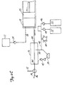
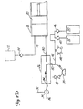
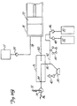
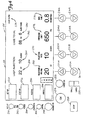
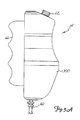
- FIG. 1 shows angiographie injector system 10 for injecting radiographic contrast material into a blood vessel under interactive physician control.
- System 10 includes main console 12, hand held remote control 14, syringe holder 16, syringe body 18, syringe plunger 20, radiographic material reservoir (bottle) 22, one-way valve 24, manifold 26, high pressure tube 28, catheter 30, patient medication port 32, three-way stop-cock 34, T-connector 36, pressure transducer 38, stop-cock 40, tubing 42, peristaltic pump 44, saline check valve 46, waste check valve 48, saline bag 50, waste bag 52, and bag support rack 54.
- Console 12 houses the electrical controls for system 10, together with the motors which drive piston 20 and peristaltic pump 44.
- user interface 54 provides control switches 56 and display 58 through which the user may enter control settings and monitor the operational state of system 10.
- Remote control 14 is connected to console 12 by cable 60 (although in other embodiments remote control 14 may be connected by a wireless connection such as an RF, infrared optic, or ultrasonic link).
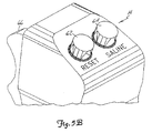
- Remote control 14 is, in the embodiment shown in Fig. 1 , a hand-held control which includes reset and saline push button switches 62 and 64, respectively, and flow rate control lever or trigger 66. By squeezing trigger 66, the user can provide a command signal to console 12 to provide a continuously variable injection rate.
- Syringe holder 16 projects from the left hand side of console 12.
- Syringe holder 16 is preferably a clear material, and includes a half cylindrical back shell 68, a half cylindrical front door 70 (which is shown in open position in Fig. 1 ), and reservoir holder 72.
- Syringe 18 is a transparent or translucent plastic cylinder having its open end 74 connected to console 12. Closed end 76 of syringe 18 contains two ports: upper port 78 and lower port 80.
- Plunger 20 is movable within syringe body 18. Plunger 20 is connected to, and driven by a motor located within console 12.
- Radiographic contrast material reservoir 22 is connected through one-way check valve 24 to upper port 78. Radiographic contrast material is drawn from reservoir 22 through check valve 24 and upper port 78 into the pumping chamber defined by syringe body 18 and plunger 20.
- Check valve 24 is preferably a weighted one-way valve which permits air to flow from syringe body 18 back into reservoir 22, but will not permit radiographic contrast material to flow from syringe body 18 to reservoir 22. This permits automatic purging of air from the system, as will be described in more detail later.
- Lower port 80 of syringe body 18 is connected to manifold 26.
- Manifold 26 includes a spring biased spool valve which normally connects transducer/saline port 82 and patient port 84. When radiographic contrast material is to be injected, the pressure of the radiographic material causes the spool valve to change states so that lower port 80 is connected to patient port 84.
- High pressure tube 28 is a flexible tube which connects patient port 84 to catheter 30.
- Three-way stop-cock 34 is located at the distal end of tube 28.
- Rotatable luer lock connector 86 is connected to stop-cock 34 and mates with luer connector 88 at the proximal end of catheter 30.
- Stop-cock 34 either blocks flow between tube 28 and catheter 30, permits flow, or connects medication port 32 to catheter 30.
- system 10 In addition to injecting radiographic material into a patient through catheter 30, system 10 also permits other related functions to be performed.
- a device for delivering the patient medication (not shown in Fig. 1 ) may be connected to medication port 32 when medication is to be delivered through catheter 30 to the patient,
- pressure transducer 38 monitors the blood pressure through the column of fluid which extends from catheter 30, tube 28, patient port 84, manifold 26, transducer/saline port 82, tubing 90, T-connector 36, and tubing 92.
- Transducer 38 has an associated stop-cock 40 which allows transducer 38 to be exposed to atmospheric pressure during calibration and also allows for removal expulsion of trapped air so the dome chamber of transducer 38 can be flushed with saline.
- Peristaltic pump 44 supplies saline solution from bag 50 through saline check valve 46, tubing 42, T-connector 36 and tubing 90 to saline port 82.
- peristaltic pump 44 When peristaltic pump 44 is operating to supply saline solution, the saline solution is supplied through manifold 26 to patient port 84 and then through tube 28 to catheter 30.
- Peristaltic pump 44 also operates in an opposite direction to draw fluid from catheter 30 and through tube 28, manifold 26, tubing 90, T-connector 36 and tubing 42 to waste check valve 48 and then into waste collection bag 52.
- syringe body 18, manifold 26, tube 28, catheter 30, T-connector 36, tubing 42, check valves 46 and 48, bags 50 and 52, and tubing 90 and 92 are all disposable items. They must be installed in system 10 each time an angiography procedure is to be performed with a new patient. Once system 10 is set up with all the disposable items installed, door 70 is closed, and syringe body 18 filled with contrast material and purged of air, the user (typically a physician) enters into system 10 the safety parameters that will apply to the injection of radiographic contrast material.
- safety parameters typically include the maximum amount of radiographic contrast material to be injected during any one injection, the maximum flow rate of the injection, the maximum pressure developed within syringe body 18, and the maximum rise time or acceleration of the injection.
- the user operates remote control 14 by squeezing trigger 66.
- system 10 causes the flow rate of the injection to increase as the force or distance of travel of trigger 66 is increased.
- System 10 allows the user to tailor the contrast injections to the needs of the patient, thereby maximizing the quality of the procedure, increasing the safety, and reducing the amount of contrast material required to perform the fluoroscopic examination.
- Figs. 2A-2G are diagrams illustrating fluid flow paths during seven different operations of system 10. Those operations are contrast fill ( Fig. 2A ), air purge ( Fig. 2B ), patient inject ( Fig. 2C ), patient pressure ( Fig. 2D ), saline flush ( Fig. 2E ), aspirate waste ( Fig. 2F ), and medicate patient ( Fig. 2G ).
- the contrast fill operation illustrated in Fig. 2A involves the filling of syringe body 18 with radiographic contrast material from reservoir (contrast media supply) 22, The contrast fill operation is performed during initial set up of system 14, and may be repeated during operation of system 10 whenever syringe body 18 is running low on radiographic contrast material.
- plunger 20 is initially driven to its furthest forward position adjacent closed end 76 of syringe body 18. This will expel to the atmosphere the majority of the air which is located within syringe body 18.
- Plunger 20 is then retracted, which creates a vacuum within syringe body 18 which draws contrast material from reservoir 22 through check valve 24 into syringe body 18 through upper port 78.
- the Contrast Fill operation typically will result in some air being drawn into or remaining within syringe body 18. It is important, of course, to prevent air from being injected into the patient through catheter 30. That is the purpose of the Air Purge operation shown in Fig. 2B , Also, the location of two ports at different elevations allows for a greater amount of safety in preventing air bubbles in the injection.
- one-way valve 24 is a weighted one-way valve which allows flow of radiographic contrast material from reservoir 22 to upper port 78, but will not allow radiographic contrast material to flow in the opposite direction from upper port 78 to reservoir 22. Valve 24 will, however, allow air to flow from port 78 to reservoir 22. As soon as radiographic contrast material begins flowing out of syringe body 18 through upper port 78 to valve 24, valve 24 closes to prevent any further flow toward reservoir 22.
- Valve 24 can also, in alternative embodiments, can be a solenoid actuated or motor driven valve operated under control of the electric circuitry within console 12, In either case, valve 24 is capable to withstanding the relatively high pressures to which it will be subjected during the inject operation. Preferably, valve 24 is capable of withstanding static fluid pressures up to about 82,7 bar (1200 p.s.i.).
- Fig. 2C illustrates the Patient Inject operation.
- Plunger 20 travels forward under the interactive control of the user, who is controlling trigger 66 of remote control 14.
- the movement of plunger 20 creates hydraulic pressure to force contrast material out of syringe body 18 through lower port 80 and through manifold 26 and high pressure tube 28 into catheter 30.
- syringe lower port 80 and patient port 84 are connected for fluid flow during the patient inject operation.
- Manifold 26 contains a valve which controls the routing of fluid connections between patient port 84 and either syringe bottom port 80 or transducer/saline port 82.
- manifold 26 includes a spool valve which is spring biased so that patient port 84 is normally connected to transducer/saline port 82 (as illustrated in Figs. 2A and 2B ).
- the spool valve opens automatically during the patient inject operation in response to increase pressure exerted on it from the syringe lower port 80.
- the spool valve closes and returns to its original position allowing for connection of patient port 84 to transducer 38 when a slight vacuum is applied by retraction of plunger 20 at the end of each Patient Inject operation.
- the valve within manifold 26 is an electromechanical or motor driven valve which is actuated at appropriate times to connect either syringe lower port 80 or transducer/saline port 82 to patient port 84.
- the actuator mechanism is controlled by console 12, Once again in this alternative embodiment, the valve protects pressure transducer 38 from being exposed to high pressure.
- Fig. 2D illustrates the Patient Pressure operation.
- System 10 allows for reading of the patient's blood pressure, which is monitored through catheter 30.
- Patient blood pressure can be monitored through the use of pressure transducer 38 at any time except during the patient inject, saline flush, and waste aspirate operations.
- the pressure reading being produced by pressure transducer 38 may be normalized by manually opening stop-cock 40 and closing stop-cock 34 to expose pressure transducer 38 to atmospheric pressure.
- saline solution is used to flush all of the internal lines, pressure transducer chamber 38, tube 28, and catheter 30.
- peristaltic pump 44 is operating in a direction which causes saline solution to be drawn from bag 50 through check valve 46 and through tubing 42 to saline port 82.
- Manifold 26 connects saline port 82 to patient port 84 so that saline solution is pumped out of patientport 84 and through tube 28 and catheter 30.
- patient port 84 is again connected to saline port 82.
- peristaltic pump 44 is operating in the opposite direction from its rotation during the saline flush operation.
- patient fluids are aspirated from patient port 84 to saline port 82 and then through tubing 42 and check valve 48 into waste collection bag 52.
- Peristaltic pump 44 acts as a valve pinching/occluding tubing 42 and preventing back flow to/from saline and waste containers 50 and 52 in conjunction with check valves 46 and 48.
- System 10 allows for that option by providing patient medication port 32. As shown in Fig. 2G , when stop-cock 34 is open, a medication source connected to port 32 will be connected to patient port 84, and thereby to catheter 30. During the medicate patient operation, peristaltic pump 44 and plunger 20 are not moving.
- Fig. 3 is an electrical block diagram of the control system which controls the operation of angiographic injector system 10.
- the electrical control system includes digital computer 100, which receives input signals from remote control 14 and front panel controls 56 through interface 102, and provides signals to display 58 to display operation data, alerts, status information and operator prompts.
- Computer 100 controls the motion of plunger 20 through a motor drive circuit which includes motor 104, motor amplifier 106, tachometer 108, potentiometer 110, a rectifier 112, pressure sensing load cell 114, and AID converter 160.
- motor drive circuit which includes motor 104, motor amplifier 106, tachometer 108, potentiometer 110, a rectifier 112, pressure sensing load cell 114, and AID converter 160.
- Motor amplifier 106 provides a Drive I signal to motor 104 in response to Control Voltage, Fwd/Rev,and/Brake signals from computer 100 and a speed feedback signal from tachometer 108 through rectifier 112,
- the outputs of tachometer 108 and potentiometer 110 are supplied to computer 100 through AID converter 116 as Speed Monitor and Position Monitor signals. These allow computer 100 to check motor speed, motor direction, and position (volume is a calculated value).
- Pressure sensor 114 senses motor current or plunger force in order to measure the pressure being applied to the radiographic contrast material within syringe body 18. This Pressure Monitor Signal is supplied through AID converter 116 and interface 102 to computer 100.
- Peristaltic pump 44 is driven under the control of computer 100 through pump motor 120, motor driver 122 and optical encoder 124.
- Computer 100 provides Saline (Forward) and Waste (Reverse) drive signals to motor driver 122 to operate pump motor 120 in a forward direction for saline flush and a reverse direction for waste aspiration.
- Optical encoder 124 provides the Speed Direction Monitor signal to interface 102 which indicates both the speed and the direction of rotation of pump motor 120.
- Fig. 3 illustrates an embodiment of the control system in which valve motor 130 is used to actuate valves such as one-way valve 24 and the valve within manifold 26.
- computer 100 controls valve motor 130 through motor driver 132, and monitors position through a Position Monitor feedback signal from potentiometer 134.
- valve motor 130 is a stepper motor.
- Computer 100 monitors temperature of the contrast material based upon a Temp Monitor signal from temperature sensor 140. Temperature sensor 140 is preferably positioned near syringe body 18. If the temperature being sensed by temperature sensor 140 is too high, computer 100 will disable operation motor 104 to discontinue patient injection. If the temperature is to low, computer 100 provides a /Temp Enable drive signal to heater drive 150, which energizes heater 152. In one preferred embodiment, heater 152 is a resistive film heater which is positioned within syringe holder 116 adjacent tosyringe body 18,
- Computer 100 also receives feedback signals from contrast bottle sensor 160, forward limit sensor 162, reverse limit sensor 164, syringe missing sensor 166, chamber open sensor 168, no contrast bubble detector 170, and air in line bubble detector 172.
- Contrast bottle sensor 160 is a miniature switch located within reservoir holder 72.
- the state of the Contrast Bottle Present signal from sensor 1 60 indicates whether a reservoir 22 is in position within holder 72. If reservoir 22 is not present, computer 100 will disable the fill operation.
- Forward limit and reverse limit sensors 162 sense the end limit positions of plunger 20. When plunger 20 reaches its forward limit position, no further forward movement of plunger 20 is permitted. Similarly, when reverse limit sensor 164 indicates that plunger 20 has reached its reverse limit position, no further reverse movements are permitted.
- Syringe missing sensor 166 is a miniature switch or infrared emitter/detector which indicates when syringe body 18 is not in position within syringe holder 16. If syringe body 18 is not in position, all movement functions are disabled except that plunger 20 can move to its reverse limit position (i.e., return to zero).
- Chamber open sensor 168 is a miniature switch or infrared emitter/detector which senses when door 70 of syringe holder 16 is open. When the signal from sensor 168 indicates that door 70 is open, all movement functions are disabled. Only when door 70 is closed and locked may any movement be allowed. When door 70 is indicated as closed and sensor 166 indicates the syringe body 18 is in position, other normal functions of the system 10 can proceed.
- Bubble detector 170 is positioned between reservoir 22 and top port 78, and is preferably an infrared emitter/detector which senses air bubbles. If an air bubble is sensed in the flow path between reservoir 22 and top port 78 during a fill operation, the fill operation is disabled until a new reservoir is connected.
- Bubble detector 172 is positioned to sense air bubbles in high pressure line 28. It is preferably an infrared emitter/detector type of bubble detector. Any air bubble which is sensed in high pressure line 28 results in the disabling of all fluid push out functions, whether the fluid is saline solution from peristaltic pump 44 or contrast material from syringe body 18.
- the control system of Fig. 3 also includes the capability to provide a control signal to x-ray equipment through relay 180 which is controlled by computer 100.
- computer 100 receives data from blood pressure transducer 38 and from an electrocardiograph (ECG) system, which is separate from injector system 10.
- ECG electrocardiograph
- the Pressure and ECG signals are received through signal conditioners and A/D converter 190, and are transferred to computer 100.
- the ECG signal is used by computer 100 in one preferred embodiment, to synchronize operation of motor 104 (and thus the Patient Inject operation) with heart beats.
- the injection of radiographic contrast material is synchronized to the coronary artery blood flow.
- the time periods of systole and diastole are determined using an electrocardiographic (ECG) electrical signal, arterial blood pressure waveform analysis, or other timing based on the heart rate.
- ECG electrocardiographic
- the injection of contrast material is interrupted during the period of systole, which reduces or stops contrast injection during this time.
- the operator can vary the rate of contrast injection into the coronary artery while computer 100 automatically pulses the contrast injection to the cardiac cycle
- the inertial forces of the moving contrast material and expansion of the containers and tubing holding the contrast material and transmitting it to the patient can cause a phase lag between movement of plunger 20 within syringe body 18 and movement of contrast material out of catheter 30 into the patient.
- a variable time offset can be entered through control panel 54 such that the timing of the cardiac cycle can be offset by a selected time. Since the magnitude of the phase lag may be dependent on the frequency of the heart rate, an algorithm within computer 100 continuously and automatically adjusts the magnitude of the time offset, based on the instantaneous heart rate during the injection of contrast material.
- FIG. 4 shows one embodiment of control panel 54 which illustrates the front panel control switches 56 and display 58 of one embodiment of the present invention.
- Front panel control switches 56 include Set Up/Fill/End switch 200, Purge switch 202, Aspirate switch 204, Saline switch 206, Enable OK switch 208, Injection Volume Limit switches 210a and 210b, Injection Flow Rate Limit switches 212a and 212b, Injection Pressure Limit switches 214a and 214b, Rise Time switches 216a and 216b, OK switch 218, Injection Range Toggle switch 220, Large Injection OK switch 222, and Stop switch 224.
- Set Up/Fill/End switch 200 is a momentary push button switch. When it is first activated, the user will be notified to place syringe 18 in syringe holder 16. When syringe 18 has been placed in syringe holder 16 (which is indicated to computer 100 by sensor 166), the user will be instructed to close and lock the chamber (i.e., to close door 70). Plunger 20 is moved to its full forward position expelling all air within the syringe. Display 58 then indicates to the operator that contrast reservoir 22 should be connected.
- contrast reservoir 22 Once contrast reservoir 22 has been put in place, the operator is requested to depress OK switch 218, at which time plunger 20 will retract at a set rate (preferably corresponding to a flow rate of 10 ml per second) to the maximum syringe volume. If the real speed (as indicated by feedback to computer 100 from AID converter 116) is greater than the set speed, system 10 will stop.
- plunger 20 is at its rearward most position, motor 104 is actuated to move plunger 20 forward to purge all air bubbles.
- Pressure sensor 114 provides an indication of when one-way valve 24 is closed and pressure is beginning to build up within syringe body 18. Once the purge is completed, the total volume injected and the number of injections counter is reset.
- switch 200 also allows for full retraction and disengagement of plunger 20 from syringe body 18.
- Purge switch 202 is a protected momentary push button switch. When activated, Purge switch 202 causes plunger 20 to move forward to expel air through top port 78. The forward movement of plunger 20 is limited and stopped when a predetermined pressure within syringe 18 is reached. This is sensed by pressure sensor 114. The purge operation which is initiated by Purge switch 202 will expel air within syringe 20. The user may also use Purge switch 202 to purge fluid through patient port 84 by depressing and holding Purge switch 202 continuously on.
- Aspirate switch 204 is a momentary push button switch which causes computer 100 to activate pump motor 120 of peristaltic pump 44. Pump motor 120 is operated to aspirate catheter 30 at a set speed, with the aspirated fluid being collected in waste bag 52. All other motion functions are disengaged during aspiration. If the real speed of motor 120 is greater than a set speed, computer 100 will stop motor 120.
- Saline switch 206 is an alternate action switch. Pump motor 120 is activated in response to Saline switch 206 being pushed on, and saline solution from bag 50 is introduced into manifold 26 and catheter 30 at a set speed. If Saline switch 206 is not pushed a second time to stop the flow of saline solution within 10 seconds, computer 100 automatically stops pump motor 120. If a time-out is reached, Saline switch 206 must be reset to its original state prior to initiating any further actions.
- Enable OK switch 208 is a momentary push button switch. After the system has detected a disabling function at the end of an injection other than a limit, Enable OK switch 208 must be activated prior to activating OK switch 218 and initiating any further function.
- Injection Volume Limit keys 210a and 210b are pushed to either increase or decrease the maximum injection volume that the system will inject during any one injection. Key 210a causes an increase in the maximum volume value, and key 210b causes a decrease. Once the maximum injection volume limit has been set, if the measured volume reaches the set value, computer 100 will stop motor 104 and will not restart until OK switch 218 has been depressed. If a large injection (i.e., greater than 10 ml) has been selected, OK switch 218 and Large Injection OK switch 220 must both be reset prior to initiating the large injection.
- Injection Flow Rate Limit keys 212a and 212b allow the physician to select the maximum flow rate that the system can reach during any one injection. If the measured rate (which is determined by the feedback signals from tachometer 108 and potentiometer 110) reaches the set value, computer 100 will control motor 104 to limit the flow rate to the set value.
- Injection Pressure Limit keys 214a and 214b allow the physician to select the maximum pressure that the system can reach during any one injection. If the measured pressure, as determined by pressure sensor 114, reaches the set value, computer 100 will control motor 104 to limit the pressure to the injection pressure limit. The injection rate will also be limited as a result.
- Rise Time keys 216a and 216b allow the physician to select the rise time that the system will allow while changing flow rate during any one injection.
- Computer 100 controls motor 104 to limit the rise time to the set value.
- keys 210a-210b, 212a-212b, 214a-214b, and 216a-216b can be replaced by other devices for selecting numerical values. These include selector dials, numerical keypads, and touch screens.
- OK switch 218 is a momentary push button switch which resets functions and hardware sensors. In response to OK switch 218 being activated, computer 100 controls display 58 to ask the operator to acknowledge that the correct function has been selected. Activation of OK switch 218 causes the status to be set to Ready.
- Injection Range switch 220 is a toggle switch. Depending on whether switch 220 is in the "small” or “large” position, it selects either a high or a low injection volume range for the next injection.
- Large Injection OK switch 222 is a momentary push button switch. When the large injection range has been selected by injection range switch 220, the Large Injection OK button 222 must be activated to enable OK switch 218. OK switch 218 must be activated prior to each injection. On large volume injections, the user is required to verify the volume selected by activating first Large Injection OK switch 222 and then OK switch 218.
- Stop switch 224 is a momentary push button switch. When stop switch 224 is pushed, it disables all functions. Display 58 remains active. Display panel 58 includes Set-Up display 250, Status display 252, Alerts display 254, Limits display 256, total number of injections display 260, total volume injection display 262, flow rate display 264, injection volume display 266, injection volume limit display 268, injection rate limit display 270, pressure limit display 272, rise time minimum display 274, large injection display 276, and real time clock display 278.
- Set-Up display 250 contains a series of messages which are displayed as the operator goes through the set up procedure. The display of messages in set up display 250 are initiated by the actuation of set up switch 200 as described previously.
- Status display 252 provides a flashing indication of one of several different operating conditions.
- these status conditions which can be displayed include “Ready”, “Set-Up”, “Injecting”, “Filling”, “Flushing”, and "Aspirating”.
- Alerts display 254 and Limits display 256 notify the operator of conditions in which system 10 has encountered a critical control parameter and will disable operation, or has reached an upper or lower limit and will continue to function in a limited fashion, or has reached an upper or lower limit and will continue to operate.
- Total number of injections display 260 displays the total number of injections (cumulative) given for the current patient case. The cumulative total volume injected during the current patient case is displayed by total volume display 262.
- Displays 264 and 266 provide information on the current or last injection.
- Display 264 shows digital value of the real time flow rate to the patient during injection. Once the injection is completed, the value displayed on display 264 represents the peak flow rate reached during that injection.
- Display 266 shows the digital value of the volume injected during the most recent injection.
- Display 268 displays the digital value of the maximum injection volume selected by operation of switches 210a and 210b.
- display 270 shows the digital value of the maximum flow rate that the system will allow, as selected by switches 212a and 212b.
- Display 272 shows the digital value of the maximum pressure that the system will allow to be developed in syringe 18.
- the pressure limit is selected by switches 214a and 214b.
- Display 274 displays the minimum rise time that the system will allow while changing flow rate.
- the minimum rise time is selected through switches 216a and 216b.
- Large injection display 276 provides a clear indication when the large injection scale has been selected by the operator.
- Real-time clock display 278 shows the current time in hours, minutes, and seconds.
- Figs. 5A and 5B show remote control 14 which includes main housing 300, which is designed to conform to the users hand.
- Trigger 66 is movable with respect to housing 300, and the position of trigger 66 generates a command signal which is a function of trigger position.
- trigger 66 is linked to a potentiometer within housing 300.
- the command signal controls the injunction flow rate or speed. The flow rate is directly proportional to trigger position.
- Reset switch 62 is a momentary push button switch whose function is identical to that of OK switch 218. Alternatively, Reset switch 62 may also be labeled "OK".
- Saline switch 64 on remote control 14 is an alternate action push button switch which is pushed to turn on and pushed again to turn off.
- the function of Saline switch 62 is the same as that of Saline switch 206 on front panel 54.
- Foot pedal remote control 14' in the form of a foot pedal is used instead of the hand held remote control 14 illustrated in Fig. 1 and in Figs. 5A and 5B .
- Foot pedal remote control 14' includes foot operated speed pedal or trigger 66' for providing a command signal, as well as Reset or OK switch 62' and Saline switch 64'. Covers 310 and 312 protect switches 62' and 64' so that they can only be actuated by hand and not accidentally by foot.
- Foot pedal remote control 14' is connected to console 12 by cable 60', but could alternatively be connected by a wireless link.
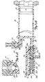
- Figs. 7A-7D and Figs. 8A-8C illustrate the construction and operation of one way valve 24 and manifold 26 during Contrast Fill, Air Purge and Patient Injection operation.
- Figs. 7A and 8A illustrate one way or check valve 24, manifold 26, syringe body 18, and plunger 20 during a Contrast Fill operation.
- Inlet check valve of one way valve 24 includes weighted ball 350 which is positioned at its lower seated position within valve chamber 352 in Figs. 7A and 7B .
- Contrast material is being drawn into syringe body 18 by the rearward movement of plunger 20. The contrast material flows through passages 354 around ball 350 and into upper port 78.
- Manifold 26 contains spring loaded spool valve 360, which includes spool body 362, shaft 364, O-rings 366, 368 and 370, bias spring 372, and retainer 374.
- bias spring 372 urges spool body 362 to its right-most position toward syringe body 18. In this position, spool body 362 blocks lower port 80 of syringe body 18 while connecting transducer saline port 82 to patient port 84 through diagonal passage 376.
- 0-rings 366 and 368 on the one hand, and O-ring 370 on the other hand, are positioned on the opposite sides of diagonal passage 376 to provide a fluid seal.
- Figs. 7B and 8B illustrate the Air Purge operation.
- Syringe body 18 has been filled with contrast fluid, but also contains trapped air.
- Plunger 20 is driven forward to force the air out of syringe body 18 through upper port 78 and through check valve 24. The force of the air may cause a slight lifting of ball 350 in check valve 20.
- Ball 350 is sufficiently heavy that the air being forced out of syringe body 18 and back toward reservoir 22 cannot lift ball 350 into its uppermost seated position where it would block the flow of air out of syringe body 18.
- spool valve 360 is in the same position as in Fig. 7A , Diagonal passage 376 connects transducer saline port 82 with patient port 84, As a result, pressure monitoring by pressure transducer 38 can be performed during the Air Purge (as well as the Contrast Fill) operation.
- Fig. 7C and 8C illustrate the state of manifold 26 and check valve 24 at the end of the Air Purge operation and at the beginning of a Patient Inject operation.
- Fig. 7D illustrates the patient inject operation.
- Plunger 20 is moving forward, and inlet check valve 24 is closed.
- the pressure at lower port 80 has become sufficiently high to overcome the bias force of spring 372.
- Spool body 362 has been driven to the left so that lower port 80 is connected to patient port 84.
- spool body 362 blocks transducer/saline port 82.
- spool valve 360 By virtue of the operation of spool valve 360, the high pressure generated by movement of plunger 20 and syringe body 18 is directly connected to patient port 84, while saline port 82 and pressure transducer 38 are protected from the high pressure.
- the pressure to actuate may be variable and determined after manufacture by increasing or decreasing the syringe preload.
- the angiographic injector system of the present invention provides interactive control of the delivery of radiographic contrast material to a catheter through a user actuated proportional control. This allows the user to adjust the flow rate of contrast material interactively as needed and as the patient's condition changes.
- syringe holder 16 may take other forms, such as an end loaded cylinder.
- manifold 26 can take other configurations and can incorporate, for example, a part of ports 78 and 80.
Abstract
Description
- This invention relates to angiography and more specifically, the injector used to inject a medical fluid such as radiographic contrast material into living organisms.
- One of the major systems in the human body is the circulatory system. The major components of the circulatory system are the heart, blood vessels, and the blood, all of which are vital to the transportation of materials between the external environment and the different cells and tissues of the human body.
- The blood vessels are the network of passageways through which the blood travels in the human body. Specifically, arteries carry the oxygenated blood away from the left ventricle of the heart. These arteries are aligned in progressively decreasing diameter and pressure capability from the aorta, which carries the blood immediately out of the heart to other major arteries, to smaller arteries, to arterioles, and finally to tiny capillaries, which feed the cells and tissues of the human body. Similarly, veins carry the oxygen depleted blood back to the right atrium of the heart using a progressively increasing diameter network of venules and veins.
- If the heart chambers, valves, arteries, veins or other capillaries connected thereto are either abnormal (such as from a birth defect), restricted (such as from atherosclerotic plaque buildup), or deteriorating (such as from aneurism formation), then a physician may need to examine the heart and connected network of vessels. The physician may also need to correct any problems encountered during the examination with a catheter or similar medical instrument.
- Angiography is a procedure used in the detection and treatment of abnormalities or restrictions in blood vessels. During angiography, a radiographic image of a vascular structure is obtained by injecting radiographic contrast material through a catheter into a vein or artery. The vascular structures fluidly connected with the vein or artery in which the injection occurred are filled with contrast material. X-rays are passed through the region of the body in which the contrast material was injected. The X-rays are absorbed by the contrast material, causing a radiographic outline or image of the blood vessel containing the contrast material. The x-ray images of the blood vessels filled with contrast material are usually recorded onto film or videotape and are displayed on a fluoroscope monitor.
- Angiography gives the doctor an image of the vascular structures in question. This image may be used solely for diagnostic purposes, or the image may be used during a procedure such as angioplasty where a balloon is inserted into the vascular system and inflated to open a stenosis caused by atherosclerotic plaque buildup.
- Currently, during angiography, after a physician places a catheter into a vein or artery (by direct insertion into the vessel or through a skin puncture site), the angiographic catheter is connected to either a manual or an automatic contrast injection mechanism.
- A simple manual contrast injection mechanism typically has a syringe and a catheter connection. The syringe includes a chamber with a plunger therein. Radiographic contrast material is suctioned into the chamber. Any air is removed by actuating the plunger while the catheter connection is facing upward so that any air, which floats on the radiographic contrast material, is ejected from the chamber into the air. The catheter connection is then attached to a catheter that is positioned in a vein or artery in the patient.
- The plunger is manually actuated to eject the radiographic contrast material from the chamber, through the catheter, and into a vein or artery. The user of the manual contrast injection mechanism may adjust the rate and volume of injection by altering the manual actuation force applied to the plunger.
- Often, more than one type of fluid injection is desired, such as a saline flush followed by the radiographic contrast material. One of the most common manual injection mechanisms used today includes a valve mechanism which controls which of the fluids will flow into the valuing mechanism and out to the catheter within the patient. The valve mechanism contains a plurality of manual valves that the user operates manually to open and close that particular fluid channel. When the user suctions or injects contrast fluid into the chamber, the fluid is pulled from the valve mechanism via the open valves. By changing the valve positions, another fluid may be injected.
- These manual injection mechanisms are typically hand actuated. This allows user control over the quantity and pressure of the injection. However, all of the manual systems are only capable of injecting the radiographic contrast material at maximum pressure that can be applied by the human hand (i.e., 150 p.s.i). Also, the quantity of radiographic contrast material is typically limited to a maximum of about 12cc. Finally, there are no safety limits on these manual contrast injection mechanisms which act to restrict or stop injections that are outside of reasonable parameters (such as rate or pressure) and no active sensors to detect air bubbles or other hazards.
- Currently used motorized injection devices consist of a syringe connected to a linear actuator. The linear actuator is connected to a motor, which is controlled electronically. The operator enters into the electronic control a fixed volume of contrast material to be injected at a fixed rate of injection. The fixed rate of injection consists of a specified initial rate of flow increase and a final rate of injection until the entire volume of contrast material is injected.
- There is no interactive control between the operator and machine, except to start or stop the injection. Any change in flow rate must occur by stopping the machine and resetting the parameters.
- The lack of ability to vary the rate of injection during the injection results in suboptimal quality of angiographic studies. This is because the optimal flow rate of injections varies considerably between patients. In the cardiovascular system, the rate and volume of contrast injection is dependent on the size of and blood flow rate within the chamber or blood vessel being injected. In many or most cases, these parameters are not known precisely.
- Moreover, the optimal rate of injection can change rapidly, as the patient's condition changes in response to drugs, illness, or normal physiology. Consequently, the initial injection of contrast material may be insufficient in flow rate to outline the structure on x-ray imaging, necessitating another injection. Conversely, an excessive flow rate might injure the chamber or blood vessel being injected, cause the catheter to be displaced (from the jet of contrast material exiting the catheter tip), or lead to toxic effects from contrast overdose (such as abnormal heart rhythm).
- At present, the operator can choose between two systems for injecting contrast material: a manual injection system which allows for a variable, operator interactive flow rate of limited flow rate and a preprogrammed motorized system without operator interactive feedback (other than the operator can start/stop the procedure).
- The present invention is an angiographie injector system which supplies radiographic contrast material to a catheter at a user determined variable flow rate which can be instantaneously and continuously varied and includes both high pressure and low pressure systems. Thee injector system includes a pump which delivers radiographic contrast material to an outlet which is connected to a catheter. A user (typically a physician) controls the flow rate of radiographic contrast material from the pump to the catheter with a user actuated proportional control. By operating the proportional control, the user can vary a command signal in order to adjust the flow rate of radiographic contrast material from the pump to the outlet during the operation of the pump. The proportional control is preferably a remote control operated by hand or foot and allows the user to interactively adjust flow rate (and thus volume of material delivered to the patient) while observing the angiographic procedure (for example on a fluoroscope monitor).
- The injector system includes a controller which is responsive to the command signal from the user actuated proportional control. Based upon that command signal, the controller controls flow rate of the radiographic contrast material from the pump to the outlet.
- The high pressure system of the injector system includes a motor driven injector pump which supplies radiographic contrast material under high pressure to a catheter. The low pressure system includes, for example, a pressure transducer for measuring blood pressure and a pump which is used to both for delivering saline solution to the patient and for aspirating waste fluid. A manifold is connected to the syringe pump, the low pressure system, the catheter which is inserted into the patient. A valve associated with the manifold is normally maintained in a first state which connects the low pressure system to the catheter through the manifold. When pressure from the syringe pump reaches a predetermined level, the valve switches to a second state which connects the syringe pump to the catheter, while disconnecting the low pressure system from the catheter.
-
-
Fig. 1 is a perspective view illustrating a preferred embodiment of the angiographic injector system of the present invention. -
Figs. 2A-2G are diagrams illustrating operations of the system ofFig. 1 . -
Fig. 3 is an electrical block diagram of the control system of the injector system ofFig. 1 . -
Fig. 4 illustrates front panel controls and displays of a preferred embodiment of the injector system of the present invention. -
Figs. 5A and5B are side and partial top perspective views of the remote control of the system ofFig. 1 . -
Fig. 6 is a perspective view of a foot operated remote control. -
Figs. 7A-7D illustrate the operation of the inlet check valve and manifold during contrast fill, air purge, and patient inject operations. -
Figs. 8A-8C illustrate operation of the inlet check valve in greater detail. -
Figure 1 showsangiographie injector system 10 for injecting radiographic contrast material into a blood vessel under interactive physician control.System 10 includes main console 12, hand heldremote control 14,syringe holder 16,syringe body 18,syringe plunger 20, radiographic material reservoir (bottle) 22, one-way valve 24,manifold 26,high pressure tube 28,catheter 30,patient medication port 32, three-way stop-cock 34, T-connector 36,pressure transducer 38, stop-cock 40,tubing 42,peristaltic pump 44,saline check valve 46, waste check valve 48,saline bag 50,waste bag 52, andbag support rack 54. - Console 12 houses the electrical controls for
system 10, together with the motors which drivepiston 20 andperistaltic pump 44. On the front surface of console 12,user interface 54 provides control switches 56 anddisplay 58 through which the user may enter control settings and monitor the operational state ofsystem 10. -
Remote control 14 is connected to console 12 by cable 60 (although in other embodimentsremote control 14 may be connected by a wireless connection such as an RF, infrared optic, or ultrasonic link).Remote control 14 is, in the embodiment shown inFig. 1 , a hand-held control which includes reset and saline push button switches 62 and 64, respectively, and flow rate control lever ortrigger 66. By squeezingtrigger 66, the user can provide a command signal to console 12 to provide a continuously variable injection rate. -
Syringe holder 16 projects from the left hand side of console 12.Syringe holder 16 is preferably a clear material, and includes a halfcylindrical back shell 68, a half cylindrical front door 70 (which is shown in open position inFig. 1 ), andreservoir holder 72. -
Syringe 18 is a transparent or translucent plastic cylinder having itsopen end 74 connected to console 12. Closed end 76 ofsyringe 18 contains two ports:upper port 78 andlower port 80. -
Plunger 20 is movable withinsyringe body 18.Plunger 20 is connected to, and driven by a motor located within console 12. - Radiographic
contrast material reservoir 22 is connected through one-way check valve 24 toupper port 78. Radiographic contrast material is drawn fromreservoir 22 throughcheck valve 24 andupper port 78 into the pumping chamber defined bysyringe body 18 andplunger 20. Checkvalve 24 is preferably a weighted one-way valve which permits air to flow fromsyringe body 18 back intoreservoir 22, but will not permit radiographic contrast material to flow fromsyringe body 18 toreservoir 22. This permits automatic purging of air from the system, as will be described in more detail later. -
Lower port 80 ofsyringe body 18 is connected tomanifold 26.Manifold 26 includes a spring biased spool valve which normally connects transducer/saline port 82 andpatient port 84. When radiographic contrast material is to be injected, the pressure of the radiographic material causes the spool valve to change states so thatlower port 80 is connected topatient port 84. -
High pressure tube 28 is a flexible tube which connectspatient port 84 tocatheter 30. Three-way stop-cock 34 is located at the distal end oftube 28. Rotatableluer lock connector 86 is connected to stop-cock 34 and mates withluer connector 88 at the proximal end ofcatheter 30. Stop-cock 34 either blocks flow betweentube 28 andcatheter 30, permits flow, or connectsmedication port 32 tocatheter 30. - In addition to injecting radiographic material into a patient through
catheter 30,system 10 also permits other related functions to be performed. A device for delivering the patient medication (not shown inFig. 1 ) may be connected tomedication port 32 when medication is to be delivered throughcatheter 30 to the patient, - When
catheter 30 is in place in the patient, and an injection of radiographic contrast material is not taking place,pressure transducer 38 monitors the blood pressure through the column of fluid which extends fromcatheter 30,tube 28,patient port 84,manifold 26, transducer/saline port 82,tubing 90, T-connector 36, andtubing 92.Transducer 38 has an associated stop-cock 40 which allowstransducer 38 to be exposed to atmospheric pressure during calibration and also allows for removal expulsion of trapped air so the dome chamber oftransducer 38 can be flushed with saline. -
Peristaltic pump 44 supplies saline solution frombag 50 throughsaline check valve 46,tubing 42, T-connector 36 andtubing 90 tosaline port 82. Whenperistaltic pump 44 is operating to supply saline solution, the saline solution is supplied throughmanifold 26 topatient port 84 and then throughtube 28 tocatheter 30. -
Peristaltic pump 44 also operates in an opposite direction to draw fluid fromcatheter 30 and throughtube 28,manifold 26,tubing 90, T-connector 36 andtubing 42 to waste check valve 48 and then intowaste collection bag 52. - In a preferred embodiment of the present invention,
syringe body 18,manifold 26,tube 28,catheter 30, T-connector 36,tubing 42,check valves 46 and 48,bags tubing system 10 each time an angiography procedure is to be performed with a new patient. Oncesystem 10 is set up with all the disposable items installed,door 70 is closed, andsyringe body 18 filled with contrast material and purged of air, the user (typically a physician) enters intosystem 10 the safety parameters that will apply to the injection of radiographic contrast material. These safety parameters typically include the maximum amount of radiographic contrast material to be injected during any one injection, the maximum flow rate of the injection, the maximum pressure developed withinsyringe body 18, and the maximum rise time or acceleration of the injection. To actuate an injection of contrast material, the user operatesremote control 14 by squeezingtrigger 66. Within the preset safety parameters,system 10 causes the flow rate of the injection to increase as the force or distance of travel oftrigger 66 is increased. - Typically, the user will meter the amount and rate of contrast material injected based upon continuous observation of the contrast outflow into the structure being injected using fluoroscopy or other imaging methods.
System 10 allows the user to tailor the contrast injections to the needs of the patient, thereby maximizing the quality of the procedure, increasing the safety, and reducing the amount of contrast material required to perform the fluoroscopic examination. -
Figs. 2A-2G are diagrams illustrating fluid flow paths during seven different operations ofsystem 10. Those operations are contrast fill (Fig. 2A ), air purge (Fig. 2B ), patient inject (Fig. 2C ), patient pressure (Fig. 2D ), saline flush (Fig. 2E ), aspirate waste (Fig. 2F ), and medicate patient (Fig. 2G ). - The contrast fill operation illustrated in
Fig. 2A involves the filling ofsyringe body 18 with radiographic contrast material from reservoir (contrast media supply) 22, The contrast fill operation is performed during initial set up ofsystem 14, and may be repeated during operation ofsystem 10 wheneversyringe body 18 is running low on radiographic contrast material. - During initial set up of
system 10,plunger 20 is initially driven to its furthest forward position adjacent closed end 76 ofsyringe body 18. This will expel to the atmosphere the majority of the air which is located withinsyringe body 18. -
Plunger 20 is then retracted, which creates a vacuum withinsyringe body 18 which draws contrast material fromreservoir 22 throughcheck valve 24 intosyringe body 18 throughupper port 78. - The Contrast Fill operation typically will result in some air being drawn into or remaining within
syringe body 18. It is important, of course, to prevent air from being injected into the patient throughcatheter 30. That is the purpose of the Air Purge operation shown inFig. 2B , Also, the location of two ports at different elevations allows for a greater amount of safety in preventing air bubbles in the injection. - During the Air Purge operation,
plunger 20 travels forward to expel trapped air withinsyringe body 18. The air, being lighter than the contrast material, gathers near the top ofsyringe body 18. Asplunger 20 moves forward, the air is expelled fromsyringe body 18 throughupper port 78 and one-way valve 24, In the embodiment illustrated inFig. 2B , one-way valve 24 is a weighted one-way valve which allows flow of radiographic contrast material fromreservoir 22 toupper port 78, but will not allow radiographic contrast material to flow in the opposite direction fromupper port 78 toreservoir 22.Valve 24 will, however, allow air to flow fromport 78 toreservoir 22. As soon as radiographic contrast material begins flowing out ofsyringe body 18 throughupper port 78 tovalve 24,valve 24 closes to prevent any further flow towardreservoir 22. -
Valve 24 can also, in alternative embodiments, can be a solenoid actuated or motor driven valve operated under control of the electric circuitry within console 12, In either case,valve 24 is capable to withstanding the relatively high pressures to which it will be subjected during the inject operation. Preferably,valve 24 is capable of withstanding static fluid pressures up to about 82,7 bar (1200 p.s.i.). -
Fig. 2C illustrates the Patient Inject operation.Plunger 20 travels forward under the interactive control of the user, who is controllingtrigger 66 ofremote control 14. The movement ofplunger 20 creates hydraulic pressure to force contrast material out ofsyringe body 18 throughlower port 80 and throughmanifold 26 andhigh pressure tube 28 intocatheter 30. As shown inFig. 2C , syringelower port 80 andpatient port 84 are connected for fluid flow during the patient inject operation. -
Manifold 26 contains a valve which controls the routing of fluid connections betweenpatient port 84 and eithersyringe bottom port 80 or transducer/saline port 82. In one embodiment of the present invention,manifold 26 includes a spool valve which is spring biased so thatpatient port 84 is normally connected to transducer/saline port 82 (as illustrated inFigs. 2A and2B ). When the pressure atsyringe bottom port 80 builds with the movement ofplunger 20 forward, the bias force against the spool valve is overcome so thatsyringe bottom port 80 is connected topatient port 84, and transducer/saline port 82 is disconnected the valve withinmanifold 26 protectspressure transducer 38 from being exposed to the high pressure generated by the patient inject operation. - The spool valve opens automatically during the patient inject operation in response to increase pressure exerted on it from the syringe
lower port 80. The spool valve closes and returns to its original position allowing for connection ofpatient port 84 totransducer 38 when a slight vacuum is applied by retraction ofplunger 20 at the end of each Patient Inject operation. - In an alternative embodiment, the valve within
manifold 26 is an electromechanical or motor driven valve which is actuated at appropriate times to connect either syringelower port 80 or transducer/saline port 82 topatient port 84. The actuator mechanism is controlled by console 12, Once again in this alternative embodiment, the valve protectspressure transducer 38 from being exposed to high pressure. -
Fig. 2D illustrates the Patient Pressure operation.System 10 allows for reading of the patient's blood pressure, which is monitored throughcatheter 30. Patient blood pressure can be monitored through the use ofpressure transducer 38 at any time except during the patient inject, saline flush, and waste aspirate operations. The pressure reading being produced bypressure transducer 38 may be normalized by manually opening stop-cock 40 and closing stop-cock 34 to exposepressure transducer 38 to atmospheric pressure. - During the Saline Flush operation illustrated in
Fig. 2E , saline solution is used to flush all of the internal lines,pressure transducer chamber 38,tube 28, andcatheter 30. As shown inFig. 2E ,peristaltic pump 44 is operating in a direction which causes saline solution to be drawn frombag 50 throughcheck valve 46 and throughtubing 42 tosaline port 82.Manifold 26 connectssaline port 82 topatient port 84 so that saline solution is pumped out ofpatientport 84 and throughtube 28 andcatheter 30. - During the Aspirate Waste operation,
patient port 84 is again connected tosaline port 82. During this operation,peristaltic pump 44 is operating in the opposite direction from its rotation during the saline flush operation. As a result, patient fluids are aspirated frompatient port 84 tosaline port 82 and then throughtubing 42 and check valve 48 intowaste collection bag 52.Peristaltic pump 44 acts as a valve pinching/occludingtubing 42 and preventing back flow to/from saline andwaste containers check valves 46 and 48. - With
catheter 30 in place within the patient, it may be desirable to supply patient medication.System 10 allows for that option by providingpatient medication port 32. As shown inFig. 2G , when stop-cock 34 is open, a medication source connected to port 32 will be connected topatient port 84, and thereby tocatheter 30. During the medicate patient operation,peristaltic pump 44 andplunger 20 are not moving. -
Fig. 3 is an electrical block diagram of the control system which controls the operation ofangiographic injector system 10. The electrical control system includesdigital computer 100, which receives input signals fromremote control 14 and front panel controls 56 throughinterface 102, and provides signals to display 58 to display operation data, alerts, status information and operator prompts. -
Computer 100 controls the motion ofplunger 20 through a motor drive circuit which includesmotor 104, motor amplifier 106,tachometer 108,potentiometer 110, a rectifier 112, pressure sensingload cell 114, andAID converter 160. - Motor amplifier 106 provides a Drive I signal to
motor 104 in response to Control Voltage, Fwd/Rev,and/Brake signals fromcomputer 100 and a speed feedback signal fromtachometer 108 through rectifier 112, The outputs oftachometer 108 andpotentiometer 110 are supplied tocomputer 100 throughAID converter 116 as Speed Monitor and Position Monitor signals. These allowcomputer 100 to check motor speed, motor direction, and position (volume is a calculated value). -
Pressure sensor 114 senses motor current or plunger force in order to measure the pressure being applied to the radiographic contrast material withinsyringe body 18. This Pressure Monitor Signal is supplied throughAID converter 116 andinterface 102 tocomputer 100. -
Peristaltic pump 44 is driven under the control ofcomputer 100 throughpump motor 120,motor driver 122 andoptical encoder 124.Computer 100 provides Saline (Forward) and Waste (Reverse) drive signals tomotor driver 122 to operatepump motor 120 in a forward direction for saline flush and a reverse direction for waste aspiration.Optical encoder 124 provides the Speed Direction Monitor signal to interface 102 which indicates both the speed and the direction of rotation ofpump motor 120. -
Fig. 3 illustrates an embodiment of the control system in whichvalve motor 130 is used to actuate valves such as one-way valve 24 and the valve withinmanifold 26. In this embodiment,computer 100controls valve motor 130 throughmotor driver 132, and monitors position through a Position Monitor feedback signal frompotentiometer 134. In this particular embodiment,valve motor 130 is a stepper motor. -
Computer 100 monitors temperature of the contrast material based upon a Temp Monitor signal fromtemperature sensor 140.Temperature sensor 140 is preferably positioned nearsyringe body 18. If the temperature being sensed bytemperature sensor 140 is too high,computer 100 will disableoperation motor 104 to discontinue patient injection. If the temperature is to low,computer 100 provides a /Temp Enable drive signal to heater drive 150, which energizes heater 152. In one preferred embodiment, heater 152 is a resistive film heater which is positioned withinsyringe holder 116 adjacenttosyringe body 18, -
Computer 100 also receives feedback signals fromcontrast bottle sensor 160, forward limit sensor 162,reverse limit sensor 164,syringe missing sensor 166, chamberopen sensor 168, nocontrast bubble detector 170, and air inline bubble detector 172. - Contrast
bottle sensor 160 is a miniature switch located withinreservoir holder 72. The state of the Contrast Bottle Present signal fromsensor 1 60 indicates whether areservoir 22 is in position withinholder 72. Ifreservoir 22 is not present,computer 100 will disable the fill operation. - Forward limit and reverse limit sensors 162 sense the end limit positions of
plunger 20. Whenplunger 20 reaches its forward limit position, no further forward movement ofplunger 20 is permitted. Similarly, whenreverse limit sensor 164 indicates thatplunger 20 has reached its reverse limit position, no further reverse movements are permitted. -
Syringe missing sensor 166 is a miniature switch or infrared emitter/detector which indicates whensyringe body 18 is not in position withinsyringe holder 16. Ifsyringe body 18 is not in position, all movement functions are disabled except thatplunger 20 can move to its reverse limit position (i.e., return to zero). - Chamber
open sensor 168 is a miniature switch or infrared emitter/detector which senses whendoor 70 ofsyringe holder 16 is open. When the signal fromsensor 168 indicates thatdoor 70 is open, all movement functions are disabled. Only whendoor 70 is closed and locked may any movement be allowed. Whendoor 70 is indicated as closed andsensor 166 indicates thesyringe body 18 is in position, other normal functions of thesystem 10 can proceed. -
Bubble detector 170 is positioned betweenreservoir 22 andtop port 78, and is preferably an infrared emitter/detector which senses air bubbles. If an air bubble is sensed in the flow path betweenreservoir 22 andtop port 78 during a fill operation, the fill operation is disabled until a new reservoir is connected. -
Bubble detector 172 is positioned to sense air bubbles inhigh pressure line 28. It is preferably an infrared emitter/detector type of bubble detector. Any air bubble which is sensed inhigh pressure line 28 results in the disabling of all fluid push out functions, whether the fluid is saline solution fromperistaltic pump 44 or contrast material fromsyringe body 18. - The control system of
Fig. 3 also includes the capability to provide a control signal to x-ray equipment through relay 180 which is controlled bycomputer 100. In addition,computer 100 receives data fromblood pressure transducer 38 and from an electrocardiograph (ECG) system, which is separate frominjector system 10. The Pressure and ECG signals are received through signal conditioners and A/D converter 190, and are transferred tocomputer 100. The ECG signal is used bycomputer 100 in one preferred embodiment, to synchronize operation of motor 104 (and thus the Patient Inject operation) with heart beats. - Blood flow to the heart occurs predominantly in diastole (when the heart is between contractions). Continuous injection of contrast material results in spillage of the contrast material into the aorta during systole (during contraction). By injecting primarily during diastole, contrast dosage can be reduced without impairing the completeness of the contrast injection into the coronary artery.
- In a preferred embodiment, the injection of radiographic contrast material is synchronized to the coronary artery blood flow. The time periods of systole and diastole are determined using an electrocardiographic (ECG) electrical signal, arterial blood pressure waveform analysis, or other timing based on the heart rate. By controlling speed of
motor 104, speed and therefore movement ofplunger 20, the injection of contrast material is interrupted during the period of systole, which reduces or stops contrast injection during this time. In combination withremote control 14, the operator can vary the rate of contrast injection into the coronary artery whilecomputer 100 automatically pulses the contrast injection to the cardiac cycle The inertial forces of the moving contrast material and expansion of the containers and tubing holding the contrast material and transmitting it to the patient can cause a phase lag between movement ofplunger 20 withinsyringe body 18 and movement of contrast material out ofcatheter 30 into the patient. To adjust to the phase lag between theplunger 20 movement and contrast expulsion into the patient, a variable time offset can be entered throughcontrol panel 54 such that the timing of the cardiac cycle can be offset by a selected time. Since the magnitude of the phase lag may be dependent on the frequency of the heart rate, an algorithm withincomputer 100 continuously and automatically adjusts the magnitude of the time offset, based on the instantaneous heart rate during the injection of contrast material. -
Fig. 4 shows one embodiment ofcontrol panel 54 which illustrates the front panel control switches 56 anddisplay 58 of one embodiment of the present invention. Front panel control switches 56 include Set Up/Fill/End switch 200,Purge switch 202,Aspirate switch 204,Saline switch 206, EnableOK switch 208, Injection Volume Limit switches 210a and 210b, Injection Flow Rate Limit switches 212a and 212b, Injection Pressure Limit switches 214a and 214b, Rise Time switches 216a and 216b,OK switch 218, InjectionRange Toggle switch 220, Large InjectionOK switch 222, and Stopswitch 224. - Set Up/Fill/
End switch 200 is a momentary push button switch. When it is first activated, the user will be notified to placesyringe 18 insyringe holder 16. Whensyringe 18 has been placed in syringe holder 16 (which is indicated tocomputer 100 by sensor 166), the user will be instructed to close and lock the chamber (i.e., to close door 70).Plunger 20 is moved to its full forward position expelling all air within the syringe.Display 58 then indicates to the operator that contrastreservoir 22 should be connected. Oncecontrast reservoir 22 has been put in place, the operator is requested to depressOK switch 218, at whichtime plunger 20 will retract at a set rate (preferably corresponding to a flow rate of 10 ml per second) to the maximum syringe volume. If the real speed (as indicated by feedback tocomputer 100 from AID converter 116) is greater than the set speed,system 10 will stop. - Once
plunger 20 is at its rearward most position,motor 104 is actuated to moveplunger 20 forward to purge all air bubbles.Pressure sensor 114 provides an indication of when one-way valve 24 is closed and pressure is beginning to build up withinsyringe body 18. Once the purge is completed, the total volume injected and the number of injections counter is reset. - The actuation of
switch 200 also allows for full retraction and disengagement ofplunger 20 fromsyringe body 18. -
Purge switch 202 is a protected momentary push button switch. When activated,Purge switch 202 causesplunger 20 to move forward to expel air throughtop port 78. The forward movement ofplunger 20 is limited and stopped when a predetermined pressure withinsyringe 18 is reached. This is sensed bypressure sensor 114. The purge operation which is initiated byPurge switch 202 will expel air withinsyringe 20. The user may also usePurge switch 202 to purge fluid throughpatient port 84 by depressing and holdingPurge switch 202 continuously on. -
Aspirate switch 204 is a momentary push button switch which causescomputer 100 to activatepump motor 120 ofperistaltic pump 44.Pump motor 120 is operated to aspiratecatheter 30 at a set speed, with the aspirated fluid being collected inwaste bag 52. All other motion functions are disengaged during aspiration. If the real speed ofmotor 120 is greater than a set speed,computer 100 will stopmotor 120. -
Saline switch 206 is an alternate action switch.Pump motor 120 is activated in response toSaline switch 206 being pushed on, and saline solution frombag 50 is introduced intomanifold 26 andcatheter 30 at a set speed. IfSaline switch 206 is not pushed a second time to stop the flow of saline solution within 10 seconds,computer 100 automatically stopspump motor 120. If a time-out is reached,Saline switch 206 must be reset to its original state prior to initiating any further actions. - Enable
OK switch 208 is a momentary push button switch. After the system has detected a disabling function at the end of an injection other than a limit, EnableOK switch 208 must be activated prior to activatingOK switch 218 and initiating any further function. - Injection Volume Limit keys 210a and 210b are pushed to either increase or decrease the maximum injection volume that the system will inject during any one injection. Key 210a causes an increase in the maximum volume value, and key 210b causes a decrease. Once the maximum injection volume limit has been set, if the measured volume reaches the set value,
computer 100 will stopmotor 104 and will not restart untilOK switch 218 has been depressed. If a large injection (i.e., greater than 10 ml) has been selected,OK switch 218 and Large InjectionOK switch 220 must both be reset prior to initiating the large injection. - Injection Flow Rate Limit keys 212a and 212b allow the physician to select the maximum flow rate that the system can reach during any one injection. If the measured rate (which is determined by the feedback signals from
tachometer 108 and potentiometer 110) reaches the set value,computer 100 will controlmotor 104 to limit the flow rate to the set value. - Injection Pressure Limit keys 214a and 214b allow the physician to select the maximum pressure that the system can reach during any one injection. If the measured pressure, as determined by
pressure sensor 114, reaches the set value,computer 100 will controlmotor 104 to limit the pressure to the injection pressure limit. The injection rate will also be limited as a result. - Rise Time keys 216a and 216b allow the physician to select the rise time that the system will allow while changing flow rate during any one injection.
Computer 100 controls motor 104 to limit the rise time to the set value. In alternative embodiments, keys 210a-210b, 212a-212b, 214a-214b, and 216a-216b can be replaced by other devices for selecting numerical values. These include selector dials, numerical keypads, and touch screens. -
OK switch 218 is a momentary push button switch which resets functions and hardware sensors. In response toOK switch 218 being activated,computer 100 controls display 58 to ask the operator to acknowledge that the correct function has been selected. Activation ofOK switch 218 causes the status to be set to Ready. -
Injection Range switch 220 is a toggle switch. Depending on whetherswitch 220 is in the "small" or "large" position, it selects either a high or a low injection volume range for the next injection. - Large Injection
OK switch 222 is a momentary push button switch. When the large injection range has been selected byinjection range switch 220, the Large InjectionOK button 222 must be activated to enableOK switch 218. OK switch 218 must be activated prior to each injection. On large volume injections, the user is required to verify the volume selected by activating first Large InjectionOK switch 222 and thenOK switch 218. -
Stop switch 224 is a momentary push button switch. Whenstop switch 224 is pushed, it disables all functions.Display 58 remains active.Display panel 58 includes Set-Up display 250,Status display 252,Alerts display 254, Limits display 256, total number of injections display 260, totalvolume injection display 262,flow rate display 264,injection volume display 266, injectionvolume limit display 268, injectionrate limit display 270,pressure limit display 272, rise timeminimum display 274, large injection display 276, and realtime clock display 278. - Set-
Up display 250 contains a series of messages which are displayed as the operator goes through the set up procedure. The display of messages in set updisplay 250 are initiated by the actuation of set upswitch 200 as described previously. -
Status display 252 provides a flashing indication of one of several different operating conditions. In the embodiment shown inFig. 4 , these status conditions which can be displayed include "Ready", "Set-Up", "Injecting", "Filling", "Flushing", and "Aspirating". - Alerts display 254 and Limits display 256 notify the operator of conditions in which
system 10 has encountered a critical control parameter and will disable operation, or has reached an upper or lower limit and will continue to function in a limited fashion, or has reached an upper or lower limit and will continue to operate. - Total number of injections display 260 displays the total number of injections (cumulative) given for the current patient case. The cumulative total volume injected during the current patient case is displayed by
total volume display 262. -
Displays Display 264 shows digital value of the real time flow rate to the patient during injection. Once the injection is completed, the value displayed ondisplay 264 represents the peak flow rate reached during that injection.Display 266 shows the digital value of the volume injected during the most recent injection. -
Display 268 displays the digital value of the maximum injection volume selected by operation of switches 210a and 210b. Similarly, display 270 shows the digital value of the maximum flow rate that the system will allow, as selected by switches 212a and 212b. -
Display 272 shows the digital value of the maximum pressure that the system will allow to be developed insyringe 18. The pressure limit is selected by switches 214a and 214b. -
Display 274 displays the minimum rise time that the system will allow while changing flow rate. The minimum rise time is selected through switches 216a and 216b. - Large injection display 276 provides a clear indication when the large injection scale has been selected by the operator.
- Real-
time clock display 278 shows the current time in hours, minutes, and seconds. -
Figs. 5A and5B showremote control 14 which includesmain housing 300, which is designed to conform to the users hand.Trigger 66 is movable with respect tohousing 300, and the position oftrigger 66 generates a command signal which is a function of trigger position. In one embodiment, trigger 66 is linked to a potentiometer withinhousing 300. The command signal controls the injunction flow rate or speed. The flow rate is directly proportional to trigger position. -
Reset switch 62 is a momentary push button switch whose function is identical to that ofOK switch 218. Alternatively,Reset switch 62 may also be labeled "OK". -
Saline switch 64 onremote control 14 is an alternate action push button switch which is pushed to turn on and pushed again to turn off. The function ofSaline switch 62 is the same as that ofSaline switch 206 onfront panel 54. - As illustrated in another embodiment of the present invention, an alternative remote control 14' in the form of a foot pedal is used instead of the hand held
remote control 14 illustrated inFig. 1 and inFigs. 5A and5B . Foot pedal remote control 14' includes foot operated speed pedal or trigger 66' for providing a command signal, as well as Reset or OK switch 62' and Saline switch 64'.Covers -
Figs. 7A-7D andFigs. 8A-8C illustrate the construction and operation of oneway valve 24 andmanifold 26 during Contrast Fill, Air Purge and Patient Injection operation. -
Figs. 7A and 8A illustrate one way orcheck valve 24,manifold 26,syringe body 18, andplunger 20 during a Contrast Fill operation. Inlet check valve of oneway valve 24 includesweighted ball 350 which is positioned at its lower seated position withinvalve chamber 352 inFigs. 7A and7B . Contrast material is being drawn intosyringe body 18 by the rearward movement ofplunger 20. The contrast material flows throughpassages 354 aroundball 350 and intoupper port 78. -
Manifold 26 contains spring loadedspool valve 360, which includesspool body 362,shaft 364, O-rings bias spring 372, andretainer 374. As shown inFig. 7A , during the Contrast Fill operation,bias spring 372 urgesspool body 362 to its right-most position towardsyringe body 18. In this position,spool body 362 blockslower port 80 ofsyringe body 18 while connectingtransducer saline port 82 topatient port 84 throughdiagonal passage 376. 0-rings ring 370 on the other hand, are positioned on the opposite sides ofdiagonal passage 376 to provide a fluid seal. -
Figs. 7B and 8B illustrate the Air Purge operation.Syringe body 18 has been filled with contrast fluid, but also contains trapped air.Plunger 20 is driven forward to force the air out ofsyringe body 18 throughupper port 78 and throughcheck valve 24. The force of the air may cause a slight lifting ofball 350 incheck valve 20.Ball 350, however, is sufficiently heavy that the air being forced out ofsyringe body 18 and back towardreservoir 22 cannot liftball 350 into its uppermost seated position where it would block the flow of air out ofsyringe body 18. - During the Air Purge operation,
spool valve 360 is in the same position as inFig. 7A ,Diagonal passage 376 connectstransducer saline port 82 withpatient port 84, As a result, pressure monitoring bypressure transducer 38 can be performed during the Air Purge (as well as the Contrast Fill) operation. -
Fig. 7C and 8C illustrate the state ofmanifold 26 andcheck valve 24 at the end of the Air Purge operation and at the beginning of a Patient Inject operation. - In
Fig. 7C , all air has been expelled fromsyringe body 18. Bail 350 floats on the radiographic contrast material, so that when all air has been removed and the radiographic contrast material begins to flow out ofsyringe body 18 and throughupper port 78 tovalve chamber 352,ball 350 is moved upwards to its upper seated position.Ball 350 blocks any continued upward flow of radiographic contrast material, as is illustrated inFigs. 7C and 8C . - In the state which is illustrated in
Fig. 7C , the pressure withinsyringe body 18, and specifically the pressure inlower port 80 has not yet reached a level at which the bias force ofspring 372 has been overcome. As a result,spool body 362 has not yet moved to the left anddiagonal passage 376 continues to connecttransducer saline port 82 withpatient port 84. -
Fig. 7D illustrates the patient inject operation.Plunger 20 is moving forward, andinlet check valve 24 is closed. The pressure atlower port 80 has become sufficiently high to overcome the bias force ofspring 372.Spool body 362 has been driven to the left so thatlower port 80 is connected topatient port 84. At the sametime spool body 362 blocks transducer/saline port 82. - By virtue of the operation of
spool valve 360, the high pressure generated by movement ofplunger 20 andsyringe body 18 is directly connected topatient port 84, whilesaline port 82 andpressure transducer 38 are protected from the high pressure. The pressure to actuate may be variable and determined after manufacture by increasing or decreasing the syringe preload. - In conclusion, the angiographic injector system of the present invention provides interactive control of the delivery of radiographic contrast material to a catheter through a user actuated proportional control. This allows the user to adjust the flow rate of contrast material interactively as needed and as the patient's condition changes.
- Although the present invention has been described with reference to preferred embodiments, workers skilled in the art will recognize that changes may be made in form and detail without departing from the spirit and scope of the claims. For example,
syringe holder 16 may take other forms, such as an end loaded cylinder. Similarly, manifold 26 can take other configurations and can incorporate, for example, a part ofports - Subsequently a number of preferred options are summarized:
- 1. An angiographie injector for supplying radiographic contrast material to a catheter at a user determined continuously variable flow rate, the injector comprising: an outlet for connection to a catheter; a pump for delivering radiographic contrast material to the outlet; a user-actuated control for supplying a command signal to adjust a flow rate of the radiographic contrast material from the pump to the outlet during operation of the pump; and a controller for controlling the flow rate of the radiographic contrast material from the pump to the outlet as a function of the command signal.
In this option the user-actuated control is a proportional control.
Further, in this option of the injector the pump is driven by a motor, and the controller controls the rate of the motor as a function of the command signal. Also, it is preferred that the pump includes: a cylinder; an inlet port for connection to a supply of radiographic material; an outlet port for connection to the outlet; and a piston which is movable in the cylinder and is driven by the motor.
The injector preferably further comprises: a normally closed valve connected between the outlet port and the outlet for blocking flow of radiographic material to the outlet until a predetermined parameter is reached at the lower outlet port. Preferably, the user-actuated control is a handheld device including a hand grip and a user-operated actuator for producing the command signal. In this case the user-actuated control is a foot operated device for producing the command signal while the controller receives an electrical signal derived from a patient and coordinates operation of the pump with the electrical signal. Optionally, the electrical signal is an ECG signal.
The injector of the first option may further comprise: a bubble detector for detecting presence of an air bubble and providing a signal to the controller to cause operation of the pump to halt and optionally the bubble detector is positioned to detect presence of an air bubble between the pump and the outlet.
In a second embodiment of an angiographie injector for supplying radiographic contrast material to a catheter, the injector comprising: a pump for delivering radiographic contrast material under pressure to a catheter; a controller for controlling operation of the pump as a function of a command signal so that flow rate of radiographic contrast material from the pump to the catheter is a function of the command signal; and a remote control for allowing a user to interactively control the flow rate of the radiographic contrast material from the pump to the catheter during operation of the pump, the remote control supplying the command signal to the controller.
In this emodiment of the injector the pump includes: a syringe body; a plunger movable in the syringe body; and a plunger drive for moving the plunger under control of the controller and it is preferred that the controller receives an electrical signal derived from a patient and coordinates operation of the pump with the electrical signal.
The injector of this second embodiment further comprises: a bubble detector for detecting presence of an air bubble and providing a signal to the controller to cause operation of the pump to halt. - 2. The invention also discloses a method of supplying radiographic contrast material to a patient through a catheter inserted into the patient, the method comprising: initiating operation of a motor driven pump to deliver radiographic contrast material to the catheter as a function of motor rate; displaying a radiographic image of the patient while radiographic contrast material is being delivered by the pump to the catheter; and interactively controlling motor rate based upon the radiographic image of the patient.
The method further comprises: coordinating operation of the motor driven pump with an ECG signal derived from the patient.
It is preferred that the coordinating operation causes delivery of injection of the radiographic contrast material to be interrupted during a period of systole.
In this method a phase lag may be provided between a cardiac cycle indicated by the ECG signal and delivery of radiographic contrast material.
The method may further comprise: adjusting the phase lag as a function of instantaneous heart rate of the patient. - 3. There is further disclosed an angiographic injector for supplying radiographic contrast material to a catheter, the injector comprising: an outlet for connection to a catheter; a pump for delivering radiographic contrast material to the outlet; a controller for controlling the flow rate of the radiographic contrast material from the pump to the outlet; and a bubble detector for detecting presence of an air bubble and providing a signal to the controller to cause operation of the pump to halt.
In an injector of this third embodiment the bubble detector may be positioned to detect presence of an air bubble between the pump and the outlet. It may also be that the bubble detector is positioned to detect presence of an air bubble between a supply of radiographic contrast material and the pump. - 4. In an angiographic injector of a forth option for supplying radiographic contrast material to a catheter, the injector comprising: a pump for delivering radiographic contrast material under pressure to a catheter; a controller for controlling operation of the pump as a function of an ECG signal so that flow of radiographic contrast material from the pump through the catheter and into a coronary artery occurs primarily during diastole.
Preferably, the controller initiates operation of the pump at a variable offset with respect to the ECG signal, the variable offset being a function of instantaneous heart rate of the patient. - 5. In an angiographie injection system of another embodiment for use in
Conjunction with a catheter having a distal end for insertion into a patient and having a proximal end, the system comprising: a motor driven pump for supplying radiographic material under pressure; a low pressure system; a manifold having a first port for connection to the syringe, a second port for connection to the proximal end of the catheter, and a third port for connection to the low pressure system; and a valve, associated with the manifold, having a first state in which the second and third ports are connected, and a second state in which the first and second ports are connected, the valve being normally biased to the first state and being switchable to the second state when fluid pressure from the pump reaches a predetermined level.
In this case the low pressure system may include a pressure transducer connected to the third port. In addition it may be provided that the low pressure system further includes a pump for delivering fluid to the third port during a saline flush operation, and for aspirating fluid through the catheter and from the second port to the third port during a waste aspiration operation.
Claims (10)
- A medical fluid delivery arrangement comprising:(a) a high pressure tube (28) in fluid communication with an intravascular catheter (30);(b) a pump (18, 44) for supplying a fluid from a reservoir (22, 50); and(c) a low pressure tube (90,92) in fluid communication with a pressure sensor (38),
characterized by:(d) a manifold (26) including:(i) a first port (80) in fluid communication said pump (18, 44);(ii) a second port (84) in fluid communication with said high pressure tube (28); and(iii) a third port (82) in fluid communication with said low pressure tube (90,92);(e) wherein said manifold (26) includes a valve (360) having a first state and a mutually exclusive second state;(i) said first state being when second (84) and third (82) ports are connected;(ii) said second state being when the first (80) and second (84) ports are connected; and wherein said first (80) and third (82) ports of said valve are always disconnected in each state; and(f) said valve is normally biased to said first state and is switchable to said second state. - The medical fluid delivery arrangement of claim 1, wherein said valve (360) is a spring loaded valve.
- The medical fluid delivery arrangement of claim 1, wherein said valve (360) is a spring loaded spool valve.
- The medical fluid delivery arrangement of claim 3, wherein said spool valve comprises:a spool body (362);a shaft (364);O-rings (366, 368, 370); anda bias spring (372).
- The medical fluid delivery arrangement of any of claims 1-4, wherein said normal bias of said valve (360) is provided by a spring (372).
- The medical fluid delivery arrangement of any of claims 1-5, wherein said valve (360) remains in said first state during each of a contrast fill and an air purge operation, and switches to said second state at the beginning of a patient inject operation.
- The medical fluid delivery arrangement of any of claims 2-6, wherein said valve (360) switches to the second state once the pressure in said first port (80) is sufficient to overcome the bias force of the spring.
- The medical fluid delivery arrangement of any of claims 1-7, wherein said manifold's first port (80) is connected to a contrast agent source, said manifold's second port (84) is connected to a patient, and said manifold's third port (82) is connected to a saline source.
- The medical fluid delivery arrangement of any of claims 1-8, wherein said arrangement is used in an angiographic injector system.
- The medical fluid delivery arrangement of any of claims 1-9, further comprising a user actuated proportional control.
Applications Claiming Priority (4)
| Application Number | Priority Date | Filing Date | Title |
|---|---|---|---|
| US42530095A | 1995-04-20 | 1995-04-20 | |
| US42614895A | 1995-04-20 | 1995-04-20 | |
| EP20030023275 EP1380261B1 (en) | 1995-04-20 | 1996-04-19 | Radiographic contrast material injector |
| EP96910835A EP0821566B1 (en) | 1995-04-20 | 1996-04-19 | Angiographic injector |
Related Parent Applications (1)
| Application Number | Title | Priority Date | Filing Date |
|---|---|---|---|
| EP20030023275 Division EP1380261B1 (en) | 1995-04-20 | 1996-04-19 | Radiographic contrast material injector |
Publications (1)
| Publication Number | Publication Date |
|---|---|
| EP1920718A1 true EP1920718A1 (en) | 2008-05-14 |
Family
ID=27026635
Family Applications (3)
| Application Number | Title | Priority Date | Filing Date |
|---|---|---|---|
| EP20080100909 Withdrawn EP1920718A1 (en) | 1995-04-20 | 1996-04-19 | Radiographic contrast material injector |
| EP96910835A Expired - Lifetime EP0821566B1 (en) | 1995-04-20 | 1996-04-19 | Angiographic injector |
| EP20030023275 Expired - Lifetime EP1380261B1 (en) | 1995-04-20 | 1996-04-19 | Radiographic contrast material injector |
Family Applications After (2)
| Application Number | Title | Priority Date | Filing Date |
|---|---|---|---|
| EP96910835A Expired - Lifetime EP0821566B1 (en) | 1995-04-20 | 1996-04-19 | Angiographic injector |
| EP20030023275 Expired - Lifetime EP1380261B1 (en) | 1995-04-20 | 1996-04-19 | Radiographic contrast material injector |
Country Status (11)
| Country | Link |
|---|---|
| US (1) | US5800397A (en) |
| EP (3) | EP1920718A1 (en) |
| JP (1) | JP3882851B2 (en) |
| AT (2) | ATE251867T1 (en) |
| AU (1) | AU5391896A (en) |
| CA (1) | CA2216946C (en) |
| DE (2) | DE69637457T2 (en) |
| DK (1) | DK0821566T3 (en) |
| ES (1) | ES2205024T3 (en) |
| PT (1) | PT821566E (en) |
| WO (1) | WO1996032887A1 (en) |
Families Citing this family (209)
| Publication number | Priority date | Publication date | Assignee | Title |
|---|---|---|---|---|
| EP1258262A3 (en) | 1993-10-28 | 2002-12-18 | Medrad, Inc. | Total system for contrast delivery |
| EP0650738B1 (en) | 1993-10-28 | 2003-05-02 | Medrad, Inc. | Multi-patient fluid dispensing |
| US5840026A (en) | 1994-09-21 | 1998-11-24 | Medrad, Inc. | Patient specific dosing contrast delivery systems and methods |
| US6099502A (en) * | 1995-04-20 | 2000-08-08 | Acist Medical Systems, Inc. | Dual port syringe |
| US7267666B1 (en) | 1995-04-20 | 2007-09-11 | Acist Medical Systems, Inc. | Angiographic injector system with multiple processor redundancy |
| US6221045B1 (en) * | 1995-04-20 | 2001-04-24 | Acist Medical Systems, Inc. | Angiographic injector system with automatic high/low pressure switching |
| DE19647701A1 (en) * | 1996-11-08 | 1998-05-14 | Schering Ag | Device for obtaining constant densities of contrast media in tissues and organs |
| US5868710A (en) * | 1996-11-22 | 1999-02-09 | Liebel Flarsheim Company | Medical fluid injector |
| US6228047B1 (en) * | 1997-07-28 | 2001-05-08 | 1274515 Ontario Inc. | Method and apparatus for performing peritoneal dialysis |
| ATE386562T1 (en) * | 1997-11-07 | 2008-03-15 | Acist Medical Sys Inc | ANGIOGRAPHY SYRINGE WITH MULTIPLE REDUNDANT PROCESSORS |
| US6096011A (en) * | 1998-01-29 | 2000-08-01 | Medrad, Inc. | Aseptic connector and fluid delivery system using such an aseptic connector |
| DE19859811C2 (en) * | 1998-12-23 | 2001-05-10 | Hilekes Guido | Contrast agent injection system |
| US6055985A (en) * | 1999-04-09 | 2000-05-02 | B.H.B., L.C. | Methods for injecting a contrast medium to generate prolonged uniform vascular enhancement |
| JP4293689B2 (en) * | 1999-10-05 | 2009-07-08 | 株式会社根本杏林堂 | Contrast medium injection device |
| SE9904782D0 (en) * | 1999-12-22 | 1999-12-22 | Gambro Lundia Ab | Remote control for extracorporeal blood processing machines |
| US6626862B1 (en) * | 2000-04-04 | 2003-09-30 | Acist Medical Systems, Inc. | Fluid management and component detection system |
| US6673048B1 (en) | 2000-05-24 | 2004-01-06 | Acist Medical Systems, Inc. | Pressure sleeve assembly |
| AU8857501A (en) | 2000-09-08 | 2002-03-22 | Insulet Corp | Devices, systems and methods for patient infusion |
| US6669669B2 (en) | 2001-10-12 | 2003-12-30 | Insulet Corporation | Laminated patient infusion device |
| US7094216B2 (en) | 2000-10-18 | 2006-08-22 | Medrad, Inc. | Injection system having a pressure isolation mechanism and/or a handheld controller |
| ES2314781T3 (en) | 2000-11-09 | 2009-03-16 | Insulet Corporation | TRANSCUTANEOUS SUPPLY MEANS. |
| DE60115707T2 (en) | 2000-12-21 | 2006-08-10 | Insulet Corp., Beverly | REMOTE CONTROL MEDICAL DEVICE |
| EP1353721A2 (en) | 2001-01-23 | 2003-10-22 | University of California, Los Angeles | Method and apparatus to remove substances from vessels of the heart and other parts of the body to minimize or avoid renal or other harm or dysfunction |
| AU2002240386A1 (en) * | 2001-02-14 | 2002-08-28 | Acist Medical Systems, Inc. | Catheter fluid control system |
| JP2004532670A (en) | 2001-02-22 | 2004-10-28 | インシュレット コーポレイション | Modular infusion device and method |
| AU2002244142A1 (en) * | 2001-02-23 | 2002-09-12 | Stryker Instruments | Integrated medication delivery system |
| US20040034331A1 (en) * | 2001-02-23 | 2004-02-19 | Jason Toman | Integrated medication delivery system |
| US6699232B2 (en) * | 2001-03-01 | 2004-03-02 | Scimed Life Systems, Inc. | Fluid injection apparatus with improved contrast visualization |
| US7044933B2 (en) * | 2001-03-01 | 2006-05-16 | Scimed Life Systems, Inc. | Fluid injection system for coronary intervention |
| US6511457B2 (en) * | 2001-05-04 | 2003-01-28 | Garey Thompson | Airless syringe |
| US6896002B2 (en) * | 2001-08-21 | 2005-05-24 | Scimed Life Systems, Inc | Pressure transducer protection valve |
| US20030055380A1 (en) * | 2001-09-19 | 2003-03-20 | Flaherty J. Christopher | Plunger for patient infusion device |
| US7172572B2 (en) | 2001-10-04 | 2007-02-06 | Boston Scientific Scimed, Inc. | Manifold system for a medical device |
| US7549977B2 (en) * | 2002-12-20 | 2009-06-23 | Medrad, Inc. | Front load pressure jacket system with syringe holder and light illumination |
| US8540698B2 (en) | 2004-04-16 | 2013-09-24 | Medrad, Inc. | Fluid delivery system including a fluid path set and a check valve connector |
| US20070161970A1 (en) | 2004-04-16 | 2007-07-12 | Medrad, Inc. | Fluid Delivery System, Fluid Path Set, and Pressure Isolation Mechanism with Hemodynamic Pressure Dampening Correction |
| US20080154214A1 (en) * | 2006-12-22 | 2008-06-26 | Medrad, Inc. | Flow Based Pressure Isolation and Fluid Delivery System Including Flow Based Pressure Isolation |
| US7563249B2 (en) * | 2002-12-20 | 2009-07-21 | Medrad, Inc. | Syringe having an alignment flange, an extending lip and a radial expansion section of reduced wall thickness |
| EP1446175B1 (en) * | 2001-11-15 | 2006-11-08 | Arcomed Ag | Infusion pump |
| GB0129187D0 (en) * | 2001-12-06 | 2002-01-23 | Dca Design Int Ltd | Improvements in and relating to a medicament cartridge |
| EP1455642A4 (en) * | 2001-12-07 | 2006-12-27 | Acist Medical Sys Inc | Low pressure measurement devices in high pressure environments |
| US6834842B2 (en) | 2002-01-09 | 2004-12-28 | Scimed Life Systems, Inc. | Fluid management valve |
| US6692457B2 (en) * | 2002-03-01 | 2004-02-17 | Insulet Corporation | Flow condition sensor assembly for patient infusion device |
| US6830558B2 (en) | 2002-03-01 | 2004-12-14 | Insulet Corporation | Flow condition sensor assembly for patient infusion device |
| US6656159B2 (en) | 2002-04-23 | 2003-12-02 | Insulet Corporation | Dispenser for patient infusion device |
| US6656158B2 (en) | 2002-04-23 | 2003-12-02 | Insulet Corporation | Dispenser for patient infusion device |
| JP3854190B2 (en) * | 2002-04-26 | 2006-12-06 | 株式会社ジェイテクト | Motor control device |
| US6780170B2 (en) | 2002-05-15 | 2004-08-24 | Liebel-Flarsheim Company | Hydraulic remote for a medical fluid injector |
| US6723072B2 (en) | 2002-06-06 | 2004-04-20 | Insulet Corporation | Plunger assembly for patient infusion device |
| US20050159708A1 (en) * | 2002-07-24 | 2005-07-21 | Rudolf Sidler | Infusion pump, control program, semiconductor means and method for the dosed administration of a medicinal liquid |
| US6929619B2 (en) | 2002-08-02 | 2005-08-16 | Liebel-Flarshiem Company | Injector |
| JP2005537116A (en) * | 2002-08-31 | 2005-12-08 | ディセトロニック・ライセンシング・アクチェンゲゼルシャフト | Dosing device with temperature sensor |
| US9956377B2 (en) | 2002-09-20 | 2018-05-01 | Angiodynamics, Inc. | Method and apparatus for intra-aortic substance delivery to a branch vessel |
| US7144384B2 (en) * | 2002-09-30 | 2006-12-05 | Insulet Corporation | Dispenser components and methods for patient infusion device |
| US7192416B1 (en) | 2002-12-20 | 2007-03-20 | Medrad, Inc. | Front load pressure jacket system with grooved syringe holder |
| US7361156B2 (en) * | 2002-12-20 | 2008-04-22 | Medrad, Inc. | Pressure jacket system with pivotal locking members |
| EP1613390A2 (en) * | 2003-04-08 | 2006-01-11 | Medrad, Inc. | Fluid delivery systems, devices and methods for delivery of hazardous fluids |
| US20050020980A1 (en) * | 2003-06-09 | 2005-01-27 | Yoshio Inoue | Coupling system for an infusion pump |
| DE10346341A1 (en) * | 2003-10-06 | 2005-05-12 | Micro Mechatronic Technologies | Dosierspritzenpumpe |
| US8029454B2 (en) | 2003-11-05 | 2011-10-04 | Baxter International Inc. | High convection home hemodialysis/hemofiltration and sorbent system |
| WO2005051463A1 (en) * | 2003-11-25 | 2005-06-09 | Nemoto Kyorindo Co., Ltd | Medicine infuser |
| US7621892B2 (en) * | 2003-12-31 | 2009-11-24 | Mallinckrodt Inc. | Contrast container holder and method to fill syringes |
| US7491191B2 (en) * | 2004-02-13 | 2009-02-17 | Liebel-Flarsheim Company | Keep vein open method and injector with keep vein open function |
| CN105641776B (en) * | 2004-03-03 | 2021-03-30 | 株式会社根本杏林堂 | Chemical solution injection system, chemical solution injection device, and chemical solution heat-insulating device |
| WO2005102412A2 (en) * | 2004-04-08 | 2005-11-03 | Medrad, Inc. | Control device for a fluid delivery system |
| US7556619B2 (en) | 2004-04-16 | 2009-07-07 | Medrad, Inc. | Fluid delivery system having a fluid level sensor and a fluid control device for isolating a patient from a pump device |
| US7507221B2 (en) | 2004-10-13 | 2009-03-24 | Mallinckrodt Inc. | Powerhead of a power injection system |
| JP2008520287A (en) | 2004-11-16 | 2008-06-19 | メドラッド インコーポレーテッド | System and method for determining patient transfer function for drug infusion and modeling patient response |
| US7648483B2 (en) | 2004-11-22 | 2010-01-19 | Intelliject, Inc. | Devices, systems and methods for medicament delivery |
| US11590286B2 (en) | 2004-11-22 | 2023-02-28 | Kaleo, Inc. | Devices, systems and methods for medicament delivery |
| WO2006083876A2 (en) | 2005-02-01 | 2006-08-10 | Intelliject, Llc | Devices, systems, and methods for medicament delivery |
| US7648482B2 (en) | 2004-11-22 | 2010-01-19 | Intelliject, Inc. | Devices, systems, and methods for medicament delivery |
| US7947017B2 (en) | 2004-11-22 | 2011-05-24 | Intelliject, Inc. | Devices, systems and methods for medicament delivery |
| CN101087625B (en) | 2004-11-22 | 2012-02-22 | 因特利杰克特有限公司 | Devices and systems for medicament delivery |
| US10737028B2 (en) | 2004-11-22 | 2020-08-11 | Kaleo, Inc. | Devices, systems and methods for medicament delivery |
| EP2902053B1 (en) | 2004-11-24 | 2017-09-06 | Bayer Healthcare LLC | Devices, systems and methods for fluid delivery |
| US20060155247A1 (en) * | 2005-01-13 | 2006-07-13 | Lampropoulos Bryan R | Introducer sheath with rotatable stop cock |
| US8206360B2 (en) | 2005-02-01 | 2012-06-26 | Intelliject, Inc. | Devices, systems and methods for medicament delivery |
| US8231573B2 (en) | 2005-02-01 | 2012-07-31 | Intelliject, Inc. | Medicament delivery device having an electronic circuit system |
| US7731686B2 (en) | 2005-02-01 | 2010-06-08 | Intelliject, Inc. | Devices, systems and methods for medicament delivery |
| US9022980B2 (en) | 2005-02-01 | 2015-05-05 | Kaleo, Inc. | Medical injector simulation device |
| US8361026B2 (en) | 2005-02-01 | 2013-01-29 | Intelliject, Inc. | Apparatus and methods for self-administration of vaccines and other medicaments |
| US9011377B2 (en) | 2008-11-05 | 2015-04-21 | Bayer Medical Care Inc. | Fluid mixing control device for a multi-fluid delivery system |
| US7766883B2 (en) | 2007-10-30 | 2010-08-03 | Medrad, Inc. | System and method for proportional mixing and continuous delivery of fluids |
| US9433730B2 (en) | 2013-03-14 | 2016-09-06 | Bayer Healthcare Llc | Fluid mixing control device for a multi-fluid delivery system |
| DE102005019371B4 (en) | 2005-04-26 | 2009-04-09 | Siemens Ag | Image recording device for recording ultrasound images |
| CN101300042B (en) * | 2005-09-14 | 2012-09-19 | 阿西斯特医疗系统有限公司 | Method for providing injection surgery information in medical fluid injection system |
| EP2468350B1 (en) | 2005-11-21 | 2015-09-09 | ACIST Medical Systems, Inc. | Medical fluid injection system |
| US8852167B2 (en) * | 2005-12-01 | 2014-10-07 | Bayer Medical Care Inc. | Medical connector |
| WO2007076463A2 (en) * | 2005-12-27 | 2007-07-05 | Acist Medical Systems, Inc. | Balloon inflation device |
| US7637279B2 (en) * | 2006-01-20 | 2009-12-29 | Smiths Medical Asd, Inc. | Shuttle valve |
| US7618397B2 (en) * | 2006-04-12 | 2009-11-17 | Medrad, Inc. | Fluid delivery system with pump cassette |
| US20070250008A1 (en) * | 2006-04-20 | 2007-10-25 | Gelblum Eugene A | Fluid injection apparatus and adaptor pump therefor |
| WO2007133942A2 (en) * | 2006-05-11 | 2007-11-22 | Acist Medical System, Inc. | Air purge in a fluid injection system |
| EP3376504A1 (en) | 2006-12-29 | 2018-09-19 | Bayer Healthcare, LLC | Patient-based parameter generation systems for medical injection procedures |
| US20080172006A1 (en) * | 2007-01-15 | 2008-07-17 | Medrad, Inc. | Patency Check Compatible Check Valve And Fluid Delivery System Including The Patency Check Compatible Check Valve |
| WO2008091838A2 (en) | 2007-01-22 | 2008-07-31 | Intelliject, Inc. | Medical injector with compliance tracking and monitoring |
| US8439863B2 (en) * | 2007-05-04 | 2013-05-14 | Mallinckrodt Llc | Methods for controlling medical fluid injections |
| US8876765B2 (en) * | 2007-05-16 | 2014-11-04 | Smiths Medical Asd, Inc. | Pump module for use in a medical fluid dispensing system |
| US7951112B2 (en) * | 2007-05-16 | 2011-05-31 | Smiths Medical Asd, Inc. | Pump module for use in a medical fluid dispensing system |
| US8043075B2 (en) * | 2007-06-19 | 2011-10-25 | Smiths Medical Asd, Inc. | Progressive cavity propagation pump |
| DE102007029150A1 (en) * | 2007-06-25 | 2009-01-02 | Biotest Ag | Perfusion device for hollow organs and their use for perfusion of an explanted hollow organ |
| EP2170165B1 (en) | 2007-07-17 | 2018-12-05 | Bayer Healthcare LLC | Systems for determination of parameters for a procedure, for estimation of cardiopulmonary function and for fluid delivery |
| WO2009036413A1 (en) * | 2007-09-14 | 2009-03-19 | Medrad, Inc. | Fluid path set providing gravity flow prevention |
| US8403909B2 (en) * | 2007-10-19 | 2013-03-26 | Medrad, Inc. | Methods for capacitance volume correction in fluid delivery systems |
| ES2391718T3 (en) * | 2007-11-19 | 2012-11-29 | Mallinckrodt Llc | Fluid delivery system with multi-dose fluid source |
| USD994111S1 (en) | 2008-05-12 | 2023-08-01 | Kaleo, Inc. | Medicament delivery device cover |
| US8021344B2 (en) | 2008-07-28 | 2011-09-20 | Intelliject, Inc. | Medicament delivery device configured to produce an audible output |
| CN104587552B (en) | 2008-06-06 | 2017-11-14 | 拜耳医药保健有限公司 | For delivering fluid injection pill and the apparatus and method for handling harmful fluids to patient |
| US8057679B2 (en) | 2008-07-09 | 2011-11-15 | Baxter International Inc. | Dialysis system having trending and alert generation |
| US7981281B2 (en) * | 2008-07-09 | 2011-07-19 | Baxter International, Inc. | Dialysis system having regimen generation methodology |
| US8168063B2 (en) * | 2008-07-09 | 2012-05-01 | Baxter International Inc. | Dialysis system having filtering method for determining therapy prescriptions |
| US9514283B2 (en) | 2008-07-09 | 2016-12-06 | Baxter International Inc. | Dialysis system having inventory management including online dextrose mixing |
| US8062513B2 (en) | 2008-07-09 | 2011-11-22 | Baxter International Inc. | Dialysis system and machine having therapy prescription recall |
| EP2327432B1 (en) * | 2008-08-08 | 2012-10-17 | Mallinckrodt LLC | Power injector with automatic ram homing function |
| US7959598B2 (en) | 2008-08-20 | 2011-06-14 | Asante Solutions, Inc. | Infusion pump systems and methods |
| EP2341456A1 (en) | 2008-08-22 | 2011-07-06 | Mallinckrodt Inc. | Power injector with decay constant functionality |
| CN102202562B (en) | 2008-09-11 | 2014-04-23 | 阿西斯特医疗系统有限公司 | Physiological sensor delivery device and method |
| US9421330B2 (en) | 2008-11-03 | 2016-08-23 | Bayer Healthcare Llc | Mitigation of contrast-induced nephropathy |
| US8282829B2 (en) | 2009-05-20 | 2012-10-09 | Baxter International Inc. | System and method for automated data collection of twenty-four hour ultrafiltration and other patient parameters using wired or wireless technology |
| US8343098B2 (en) * | 2009-06-29 | 2013-01-01 | Acist Medical Systems, Inc. | Method and system for removing air from a flow path of a fluid injection device |
| US8926551B2 (en) * | 2009-07-07 | 2015-01-06 | Baxter Healthcare Inc. | Peritoneal dialysis therapy with large dialysis solution volumes |
| EP2735376B1 (en) | 2009-07-24 | 2017-08-23 | Bayer Healthcare LLC | Syringe for a fluid injector system |
| US20120157895A1 (en) * | 2009-08-26 | 2012-06-21 | The University Of Kansas | Device, system, and method for mechanosensory nerve ending stimulation |
| AU2011261296C1 (en) | 2010-06-04 | 2016-08-18 | Bayer Healthcare, Llc. | System and method for planning and monitoring multi-dose radiopharmaceutical usage on radiopharmaceutical injectors |
| JP6025718B2 (en) | 2010-06-24 | 2016-11-16 | ベイヤー メディカル ケア インク. | A model for drug propagation and parameter generation for infusion protocols |
| US8939943B2 (en) | 2011-01-26 | 2015-01-27 | Kaleo, Inc. | Medicament delivery device for administration of opioid antagonists including formulations for naloxone |
| US9084849B2 (en) | 2011-01-26 | 2015-07-21 | Kaleo, Inc. | Medicament delivery devices for administration of a medicament within a prefilled syringe |
| US8627816B2 (en) | 2011-02-28 | 2014-01-14 | Intelliject, Inc. | Medicament delivery device for administration of opioid antagonists including formulations for naloxone |
| CN103796578B (en) | 2011-05-11 | 2016-08-24 | 阿西斯特医疗系统有限公司 | Ink vessel transfusing method for sensing and system |
| CA2836042C (en) | 2011-05-12 | 2019-04-02 | Medrad, Inc. | Fluid injection system having various systems for controlling an injection procedure |
| JP5209765B2 (en) | 2011-07-28 | 2013-06-12 | プライムテック株式会社 | Fluid transport drive unit and control program for fluid transport drive unit |
| JP2014527881A (en) | 2011-09-21 | 2014-10-23 | ベイヤー メディカル ケア インク. | Continuous multi-fluid pump device, drive and actuation system and method |
| RU2497454C2 (en) * | 2012-01-24 | 2013-11-10 | Константин Анатольевич Калашников | Device for carrying out angiocoronarography |
| EP2830499B8 (en) | 2012-03-30 | 2019-04-03 | Insulet Corporation | Fluid delivery device with transcutaneous access tool, insertion mechansim and blood glucose monitoring for use therewith |
| US9486579B2 (en) | 2012-04-03 | 2016-11-08 | Bayer Healthcare Llc | High pressure sensor for use with a fluid delivery system |
| US10076630B2 (en) * | 2012-04-24 | 2018-09-18 | The Queen Elizabeth Hospital King's Lynn Nhs Foundation Trust | Device for performing regional anesthesia |
| WO2013172811A1 (en) | 2012-05-14 | 2013-11-21 | Medrad, Inc. | Systems and methods for determination of pharmaceutical fluid injection protocols based on x-ray tube voltage |
| US9522235B2 (en) | 2012-05-22 | 2016-12-20 | Kaleo, Inc. | Devices and methods for delivering medicaments from a multi-chamber container |
| EP2854649B1 (en) | 2012-05-25 | 2018-07-11 | Acist Medical Systems, Inc. | Fluid flow measurement systems and methods |
| US9393441B2 (en) | 2012-06-07 | 2016-07-19 | Bayer Healthcare Llc | Radiopharmaceutical delivery and tube management system |
| US9889288B2 (en) | 2012-06-07 | 2018-02-13 | Bayer Healthcare Llc | Tubing connectors |
| US9125976B2 (en) | 2012-06-07 | 2015-09-08 | Bayer Medical Care Inc. | Shield adapters |
| FR2991881B1 (en) | 2012-06-13 | 2014-09-05 | Medex Sa | DEVICE FOR INJECTING A LIQUID PRODUCT COMPRISING TWO MOBILE HALF-SHELLS IN ROTATION IN RELATION TO EACH OTHER |
| US9320846B2 (en) | 2012-08-28 | 2016-04-26 | Osprey Medical, Inc. | Devices and methods for modulating medium delivery |
| US10413677B2 (en) | 2012-08-28 | 2019-09-17 | Osprey Medical, Inc. | Volume monitoring device |
| US11116892B2 (en) | 2012-08-28 | 2021-09-14 | Osprey Medical, Inc. | Medium injection diversion and measurement |
| US9999718B2 (en) | 2012-08-28 | 2018-06-19 | Osprey Medical, Inc. | Volume monitoring device utilizing light-based systems |
| US10022497B2 (en) | 2012-08-28 | 2018-07-17 | Osprey Medical, Inc. | Reservoir for collection and reuse of diverted medium |
| US11219719B2 (en) | 2012-08-28 | 2022-01-11 | Osprey Medical, Inc. | Volume monitoring systems |
| US10010673B2 (en) | 2012-08-28 | 2018-07-03 | Osprey Medical, Inc. | Adjustable medium diverter |
| EP2897673B1 (en) | 2012-09-24 | 2020-01-22 | Medline Industries, Inc. | Power injector device and method of use |
| GB2506918A (en) * | 2012-10-12 | 2014-04-16 | Cambridge Consultants | Injector device |
| US9259527B2 (en) | 2012-10-17 | 2016-02-16 | Bayer Healthcare Llc | Fluid delivery system with high and low pressure hand manifold |
| EP2938376A4 (en) | 2012-12-27 | 2017-01-25 | Kaleo, Inc. | Devices, systems and methods for locating and interacting with medicament delivery systems |
| US11369739B2 (en) | 2013-01-21 | 2022-06-28 | Medline Industries, Lp | Method to provide injection system parameters for injecting fluid into patient |
| KR101511641B1 (en) * | 2013-03-06 | 2015-04-13 | 주식회사 갈렙 | Piston pump for injectting liquid |
| US9555379B2 (en) | 2013-03-13 | 2017-01-31 | Bayer Healthcare Llc | Fluid path set with turbulent mixing chamber, backflow compensator |
| WO2015073381A1 (en) | 2013-11-14 | 2015-05-21 | Epic Medical Concepts & Innovations, Inc. | Pneumatic somatosensory stimulation device and method |
| US10244951B2 (en) | 2014-06-10 | 2019-04-02 | Acist Medical Systems, Inc. | Physiological sensor delivery device and method |
| US9895488B2 (en) | 2014-06-27 | 2018-02-20 | Bayer Healthcare Llc | Conductive coding of syringe information |
| US9517307B2 (en) | 2014-07-18 | 2016-12-13 | Kaleo, Inc. | Devices and methods for delivering opioid antagonists including formulations for naloxone |
| CA2973257C (en) | 2015-01-09 | 2023-09-19 | Bayer Healthcare Llc | Multiple fluid delivery system with multi-use disposable set and features thereof |
| AU2016235054B2 (en) | 2015-03-24 | 2020-07-16 | Kaleo, Inc. | Devices and methods for delivering a lyophilized medicament |
| EP3106200A1 (en) * | 2015-06-19 | 2016-12-21 | MedTrace A/S | A system for safe radioisotope preparation and injection |
| GB2556479B (en) | 2015-06-30 | 2022-09-07 | Kaleo Inc | Auto-injectors for administration of a medicament within a prefilled syringe |
| CN106618786A (en) * | 2015-11-03 | 2017-05-10 | 青岛博首自动化设备有限公司 | Young bird automatic injection immunizing machine and young bird automatic injection immunizing method |
| WO2017091624A1 (en) | 2015-11-24 | 2017-06-01 | Insulet Corporation | Wearable automated medication delivery system |
| WO2017091584A1 (en) | 2015-11-25 | 2017-06-01 | Insulet Corporation | Wearable medication delivery device |
| EP3374905A1 (en) | 2016-01-13 | 2018-09-19 | Bigfoot Biomedical, Inc. | User interface for diabetes management system |
| CN112933333B (en) | 2016-01-14 | 2023-03-28 | 比格福特生物医药公司 | Adjusting insulin delivery rate |
| US10898638B2 (en) | 2016-03-03 | 2021-01-26 | Bayer Healthcare Llc | System and method for improved fluid delivery in multi-fluid injector systems |
| CN105664346A (en) * | 2016-03-15 | 2016-06-15 | 西安交通大学第一附属医院 | Percutaneous T-tube cholangiography agent bolus injection device |
| EP3871708A3 (en) | 2016-05-26 | 2022-01-19 | Insulet Corporation | Wearable drug delivery system comprising a prefilled cartridge |
| WO2018031891A1 (en) | 2016-08-12 | 2018-02-15 | Insulet Corporation | Plunger for drug delivery device |
| WO2018035051A1 (en) | 2016-08-14 | 2018-02-22 | Insulet Corporation | Drug delivery device with detection of position of the plunger |
| US10751485B2 (en) * | 2016-08-29 | 2020-08-25 | Cephea Valve Technologies, Inc. | Methods, systems, and devices for sealing and flushing a delivery system |
| US10751478B2 (en) | 2016-10-07 | 2020-08-25 | Insulet Corporation | Multi-stage delivery system |
| US10780217B2 (en) | 2016-11-10 | 2020-09-22 | Insulet Corporation | Ratchet drive for on body delivery system |
| JP7014797B2 (en) | 2016-12-23 | 2022-02-01 | カレオ,インコーポレイテッド | Drug delivery devices and methods for delivering drugs to babies and children |
| AU2018210313A1 (en) | 2017-01-17 | 2019-06-20 | Kaleo, Inc. | Medicament delivery devices with wireless connectivity and event detection |
| WO2018136699A1 (en) | 2017-01-19 | 2018-07-26 | Insulet Corporation | Cartridge hold-up volume reduction |
| WO2018156548A1 (en) | 2017-02-22 | 2018-08-30 | Insulet Corporation | Needle insertion mechanisms for drug containers |
| US10695485B2 (en) | 2017-03-07 | 2020-06-30 | Insulet Corporation | Very high volume user filled drug delivery device |
| US11607489B2 (en) | 2017-05-26 | 2023-03-21 | Bayer Healthcare Llc | Injector state logic with hemodynamic monitoring |
| KR101987936B1 (en) * | 2017-06-13 | 2019-06-11 | 순천향대학교 산학협력단 | Injection device for injecting contrast agent into carcass |
| US11280327B2 (en) | 2017-08-03 | 2022-03-22 | Insulet Corporation | Micro piston pump |
| US10973978B2 (en) | 2017-08-03 | 2021-04-13 | Insulet Corporation | Fluid flow regulation arrangements for drug delivery devices |
| CA3068544A1 (en) | 2017-08-31 | 2019-03-07 | Bayer Healthcare Llc | Method for dynamic pressure control in a fluid injector system |
| US11141535B2 (en) | 2017-08-31 | 2021-10-12 | Bayer Healthcare Llc | Fluid path impedance assessment for improving fluid delivery performance |
| CN110809482B (en) | 2017-08-31 | 2023-03-07 | 拜耳医药保健有限公司 | Fluid injector system volume compensation system and method |
| CA3067625A1 (en) | 2017-08-31 | 2019-03-07 | Bayer Healthcare Llc | Injector pressure calibration system and method |
| AU2018326380B2 (en) | 2017-08-31 | 2024-02-29 | Bayer Healthcare Llc | System and method for drive member position and fluid injector system mechanical calibration |
| US11786668B2 (en) | 2017-09-25 | 2023-10-17 | Insulet Corporation | Drug delivery devices, systems, and methods with force transfer elements |
| WO2019067367A1 (en) | 2017-09-26 | 2019-04-04 | Insulet Corporation | Needle mechanism module for drug delivery device |
| US11147931B2 (en) | 2017-11-17 | 2021-10-19 | Insulet Corporation | Drug delivery device with air and backflow elimination |
| USD928199S1 (en) | 2018-04-02 | 2021-08-17 | Bigfoot Biomedical, Inc. | Medication delivery device with icons |
| WO2019203895A1 (en) | 2018-04-20 | 2019-10-24 | Acist Medical Systems, Inc. | Assessment of a vessel |
| US11478162B2 (en) | 2018-05-23 | 2022-10-25 | Acist Medical Systems, Inc. | Flow measurement using image data |
| US10874803B2 (en) | 2018-05-31 | 2020-12-29 | Insulet Corporation | Drug cartridge with drive system |
| WO2019236818A1 (en) | 2018-06-06 | 2019-12-12 | Insulet Corporation | Linear shuttle pump for drug delivery |
| WO2020018433A1 (en) | 2018-07-16 | 2020-01-23 | Kaleo, Inc. | Medicament delivery devices with wireless connectivity and compliance detection |
| WO2020113006A1 (en) | 2018-11-28 | 2020-06-04 | Insulet Corporation | Drug delivery shuttle pump system and valve assembly |
| US11499841B2 (en) | 2019-04-12 | 2022-11-15 | Osprey Medical, Inc. | Energy-efficient position determining with multiple sensors |
| JP2022543523A (en) | 2019-08-09 | 2022-10-13 | カレオ,インコーポレイテッド | Device and method for delivery of substances in pre-filled syringes |
| US11369735B2 (en) | 2019-11-05 | 2022-06-28 | Insulet Corporation | Component positioning of a linear shuttle pump |
| US11633534B2 (en) | 2020-08-18 | 2023-04-25 | Acist Medical Systems, Inc. | Angiogram injections using electrocardiographic synchronization |
| CN113521434A (en) * | 2021-07-23 | 2021-10-22 | 巨翊科技(上海)有限公司 | High-pressure injection system and method |
| CN114871762B (en) * | 2022-07-12 | 2022-09-30 | 苏州恒瑞迦俐生生物医药科技有限公司 | Assembling mechanism |
Citations (13)
| Publication number | Priority date | Publication date | Assignee | Title |
|---|---|---|---|---|
| US2705501A (en) * | 1953-04-09 | 1955-04-05 | Cincinnati Shaper Co | Non-repeat valve |
| US3157201A (en) * | 1962-04-12 | 1964-11-17 | Cardiosonics Medical Instr Com | Fluid exchange valve |
| NL6402242A (en) * | 1964-03-05 | 1965-09-06 | ||
| US3672366A (en) * | 1966-11-28 | 1972-06-27 | Geoffrey Barnett Burchell | Valve and circuit for intermittent positive pressure breathing apparatus |
| US3812843A (en) * | 1973-03-12 | 1974-05-28 | Lear Siegler Inc | Method and apparatus for injecting contrast media into the vascular system |
| US3888239A (en) * | 1974-06-21 | 1975-06-10 | Morton K Rubinstein | Fluid injection system |
| US3957052A (en) * | 1974-09-13 | 1976-05-18 | Medical Development Corporation | Pumping-syringe |
| DE2500851A1 (en) * | 1974-11-27 | 1976-06-16 | Medrad Inc | INJECTOR FOR ANGIOGRAPHIC EXAMINATIONS |
| US4502508A (en) * | 1982-03-29 | 1985-03-05 | Smiths Industries Public Limited Company | Spool valve for connecting an output to one of two inputs |
| EP0389818A1 (en) * | 1989-03-28 | 1990-10-03 | Dexide, Inc. | Medical evacuation and irrigation device |
| WO1991018632A1 (en) * | 1990-05-25 | 1991-12-12 | St. Jude Medical, Inc. | Fluid control valve |
| US5147333A (en) * | 1991-05-13 | 1992-09-15 | Burron Medical Inc. | Needleless injection port with automatic backcheck valve |
| EP0702966A2 (en) * | 1994-09-21 | 1996-03-27 | Medrad Inc. | Patient specific dosing contrast delivery systems and methods |
Family Cites Families (52)
| Publication number | Priority date | Publication date | Assignee | Title |
|---|---|---|---|---|
| US3631847A (en) * | 1966-03-04 | 1972-01-04 | James C Hobbs | Method and apparatus for injecting fluid into the vascular system |
| US3623474A (en) * | 1966-07-25 | 1971-11-30 | Medrad Inc | Angiographic injection equipment |
| US3701345A (en) * | 1970-09-29 | 1972-10-31 | Medrad Inc | Angiographic injector equipment |
| US3768518A (en) * | 1971-03-01 | 1973-10-30 | V Roth | Fluid transfer valve |
| US3734258A (en) * | 1971-03-24 | 1973-05-22 | Eaton Corp | Coupling with quick release valve |
| US3768484A (en) * | 1972-10-06 | 1973-10-30 | Lawrence A Robert | Gastric cooling apparatus |
| US3910466A (en) * | 1974-01-09 | 1975-10-07 | Roean Ind | Air actuated plastic compound dispensing device |
| US4000685A (en) * | 1975-05-05 | 1977-01-04 | Montalvo Jr Edwin J | Push/pull valve for two or three way operation |
| US4044757A (en) * | 1976-01-14 | 1977-08-30 | The Kendall Company | Cholangiography device and method |
| NZ192198A (en) * | 1979-11-22 | 1984-11-09 | Allflex Int | Vacuum closed venting valve |
| US4367736A (en) * | 1980-08-25 | 1983-01-11 | Baxter Travenol Laboratories, Inc. | System for detecting bubble formation in clear and opaque fluids |
| US4370982A (en) * | 1980-09-10 | 1983-02-01 | Medrad, Inc. | Method and apparatus for injecting and for controlling the pressure of fluid being injected into a catheter |
| JPS57211361A (en) * | 1981-06-23 | 1982-12-25 | Terumo Corp | Liquid injecting apparatus |
| US4475666A (en) * | 1981-08-31 | 1984-10-09 | American Hospital Supply Corporation | Automated liquid dispenser control |
| US4444198A (en) * | 1981-12-21 | 1984-04-24 | Petre John H | Circulatory monitoring system and method |
| US4452251A (en) * | 1982-11-05 | 1984-06-05 | Medrad, Inc. | Syringe content indicating device |
| US4502488A (en) * | 1983-01-13 | 1985-03-05 | Allied Corporation | Injection system |
| US4585941A (en) * | 1983-02-28 | 1986-04-29 | E. R. Squibb & Sons, Inc. | Dosimetry system for strontium-rubidium infusion pump |
| US4854324A (en) * | 1984-01-31 | 1989-08-08 | Medrad, Inc. | Processor-controlled angiographic injector device |
| DE3576915D1 (en) * | 1984-06-06 | 1990-05-10 | Medrad Inc | ANGIOGRAPHY INJECTOR AND ANGIOGRAHY SYRINGE USED WITH THIS. |
| US4608996A (en) * | 1984-08-10 | 1986-09-02 | Cordis Corporation | External blood parameter diagnostic system |
| JPS61115539A (en) * | 1984-11-09 | 1986-06-03 | 株式会社 日立メデイコ | Digital x-ray photographing apparatus |
| US4812724A (en) * | 1984-11-13 | 1989-03-14 | Liebel-Flarsheim Corporation | Injector control |
| DE8516350U1 (en) * | 1985-06-04 | 1988-10-27 | Baxter Travenol Laboratories, Inc., Deerfield, Ill., Us | |
| US4661096A (en) * | 1985-09-06 | 1987-04-28 | Edward Teeple | Anti-air embolism and antiblood loss device for CVP catheter |
| US4596558A (en) * | 1985-09-13 | 1986-06-24 | Queen's University At Kingston | Pulsed external medication dispenser |
| US5180371A (en) * | 1986-05-30 | 1993-01-19 | Spintech, Inc. | Hypodermic anesthetic injection apparatus and method |
| US4842576A (en) * | 1986-10-15 | 1989-06-27 | Baxter International Inc. | System for generating substantially constant fluid pressure |
| US4779614A (en) * | 1987-04-09 | 1988-10-25 | Nimbus Medical, Inc. | Magnetically suspended rotor axial flow blood pump |
| US4865581A (en) * | 1987-05-29 | 1989-09-12 | Retroperfusion Systems, Inc. | Retroperfusion control apparatus, system and method |
| US5053002A (en) * | 1988-01-11 | 1991-10-01 | Olympus Corporation | Irrigation system for angioscope |
| US4921488A (en) * | 1988-01-15 | 1990-05-01 | Maitz Carlos A | Aspirator device for body fluids |
| US5084011A (en) * | 1990-01-25 | 1992-01-28 | Grady Daniel J | Method for oxygen therapy using hyperbarically oxygenated liquid |
| US4994065A (en) * | 1990-05-18 | 1991-02-19 | Zimmer, Inc. | Apparatus for dispensing low viscosity semi-fluid material under pressure |
| US5112200A (en) * | 1990-05-29 | 1992-05-12 | Nu-Tech Industries, Inc. | Hydrodynamically suspended rotor axial flow blood pump |
| US5059174A (en) * | 1990-08-23 | 1991-10-22 | Vaillancourt Vincent L | Fluid infusion delivery system |
| US5055005A (en) * | 1990-10-05 | 1991-10-08 | Kletschka Harold D | Fluid pump with levitated impeller |
| US5261883A (en) * | 1990-10-26 | 1993-11-16 | Alcon Surgical, Inc. | Portable apparatus for controlling fluid flow to a surgical site |
| US5137514A (en) * | 1990-11-01 | 1992-08-11 | Accumed Systems, Inc. | Inflation syringe assembly for percutaneous transluminal angioplasty |
| US5246012A (en) * | 1990-12-21 | 1993-09-21 | Ballard Medical Products | Bronchoalveolar lavage catheter |
| IT1244370B (en) * | 1991-01-11 | 1994-07-08 | Roerig Farmaceutici Italiana S | DEVICE FOR THE SELECTIVE COLLECTION OF BLOOD SAMPLES FROM TWO SECTIONS OF A LINE AND BY INJECTION OF DRUGS INTO THE BLOOD ITSELF |
| US5176658A (en) * | 1991-05-03 | 1993-01-05 | Sherwood Medical Company | Valve assembly for use in medical devices |
| US5213573A (en) * | 1991-08-05 | 1993-05-25 | Imed Corporation | Iv administration set infiltration monitor |
| DE69315450T2 (en) * | 1992-01-22 | 1998-05-20 | Alaris Medical Systems Inc N D | Condition determination of a liquid hose line |
| GB9203132D0 (en) * | 1992-02-14 | 1992-04-01 | Univ Southampton | Computer assisted dynamic digital angiography |
| US5259732A (en) * | 1992-04-29 | 1993-11-09 | Becton, Dickinson And Company | Syringe pump with syringe barrel position detector |
| US5342298A (en) * | 1992-07-31 | 1994-08-30 | Advanced Cardiovascular Systems, Inc. | Automated fluid pressure control system |
| GB9225014D0 (en) * | 1992-11-30 | 1993-01-20 | Univ Hospital London Dev Corp | Pulse injector for quantitative angiographic blood-flow measurements |
| US5472403A (en) * | 1993-05-11 | 1995-12-05 | The Regents Of The University Of California | Device for automatic injection of radionuclide |
| US5417213A (en) * | 1993-06-07 | 1995-05-23 | Prince; Martin R. | Magnetic resonance arteriography with dynamic intravenous contrast agents |
| US5515851A (en) * | 1993-07-30 | 1996-05-14 | Goldstein; James A. | Angiographic fluid control system |
| US5522804A (en) * | 1994-02-15 | 1996-06-04 | Lynn; Lawrence A. | Aspiration, mixing, and injection syringe |
-
1996
- 1996-04-19 JP JP53192596A patent/JP3882851B2/en not_active Expired - Lifetime
- 1996-04-19 ES ES96910835T patent/ES2205024T3/en not_active Expired - Lifetime
- 1996-04-19 EP EP20080100909 patent/EP1920718A1/en not_active Withdrawn
- 1996-04-19 EP EP96910835A patent/EP0821566B1/en not_active Expired - Lifetime
- 1996-04-19 EP EP20030023275 patent/EP1380261B1/en not_active Expired - Lifetime
- 1996-04-19 DE DE1996637457 patent/DE69637457T2/en not_active Expired - Lifetime
- 1996-04-19 AU AU53918/96A patent/AU5391896A/en not_active Abandoned
- 1996-04-19 PT PT96910835T patent/PT821566E/en unknown
- 1996-04-19 DK DK96910835T patent/DK0821566T3/en active
- 1996-04-19 WO PCT/US1996/005423 patent/WO1996032887A1/en active IP Right Grant
- 1996-04-19 CA CA 2216946 patent/CA2216946C/en not_active Expired - Lifetime
- 1996-04-19 AT AT96910835T patent/ATE251867T1/en active
- 1996-04-19 DE DE1996630370 patent/DE69630370T2/en not_active Expired - Lifetime
- 1996-04-19 AT AT03023275T patent/ATE387922T1/en not_active IP Right Cessation
-
1997
- 1997-10-07 US US08/946,293 patent/US5800397A/en not_active Expired - Lifetime
Patent Citations (13)
| Publication number | Priority date | Publication date | Assignee | Title |
|---|---|---|---|---|
| US2705501A (en) * | 1953-04-09 | 1955-04-05 | Cincinnati Shaper Co | Non-repeat valve |
| US3157201A (en) * | 1962-04-12 | 1964-11-17 | Cardiosonics Medical Instr Com | Fluid exchange valve |
| NL6402242A (en) * | 1964-03-05 | 1965-09-06 | ||
| US3672366A (en) * | 1966-11-28 | 1972-06-27 | Geoffrey Barnett Burchell | Valve and circuit for intermittent positive pressure breathing apparatus |
| US3812843A (en) * | 1973-03-12 | 1974-05-28 | Lear Siegler Inc | Method and apparatus for injecting contrast media into the vascular system |
| US3888239A (en) * | 1974-06-21 | 1975-06-10 | Morton K Rubinstein | Fluid injection system |
| US3957052A (en) * | 1974-09-13 | 1976-05-18 | Medical Development Corporation | Pumping-syringe |
| DE2500851A1 (en) * | 1974-11-27 | 1976-06-16 | Medrad Inc | INJECTOR FOR ANGIOGRAPHIC EXAMINATIONS |
| US4502508A (en) * | 1982-03-29 | 1985-03-05 | Smiths Industries Public Limited Company | Spool valve for connecting an output to one of two inputs |
| EP0389818A1 (en) * | 1989-03-28 | 1990-10-03 | Dexide, Inc. | Medical evacuation and irrigation device |
| WO1991018632A1 (en) * | 1990-05-25 | 1991-12-12 | St. Jude Medical, Inc. | Fluid control valve |
| US5147333A (en) * | 1991-05-13 | 1992-09-15 | Burron Medical Inc. | Needleless injection port with automatic backcheck valve |
| EP0702966A2 (en) * | 1994-09-21 | 1996-03-27 | Medrad Inc. | Patient specific dosing contrast delivery systems and methods |
Also Published As
| Publication number | Publication date |
|---|---|
| PT821566E (en) | 2004-03-31 |
| WO1996032887A1 (en) | 1996-10-24 |
| DK0821566T3 (en) | 2004-01-26 |
| ATE387922T1 (en) | 2008-03-15 |
| AU5391896A (en) | 1996-11-07 |
| DE69637457D1 (en) | 2008-04-17 |
| CA2216946A1 (en) | 1996-10-24 |
| DE69630370T2 (en) | 2004-06-24 |
| US5800397A (en) | 1998-09-01 |
| DE69630370D1 (en) | 2003-11-20 |
| ATE251867T1 (en) | 2003-11-15 |
| EP1380261A3 (en) | 2004-06-09 |
| CA2216946C (en) | 2008-07-08 |
| ES2205024T3 (en) | 2004-05-01 |
| JP3882851B2 (en) | 2007-02-21 |
| EP1380261B1 (en) | 2008-03-05 |
| JPH11503939A (en) | 1999-04-06 |
| EP0821566A4 (en) | 1998-10-07 |
| EP1380261A2 (en) | 2004-01-14 |
| EP0821566B1 (en) | 2003-10-15 |
| EP0821566A1 (en) | 1998-02-04 |
| DE69637457T2 (en) | 2008-10-02 |
Similar Documents
| Publication | Publication Date | Title |
|---|---|---|
| EP0821566B1 (en) | Angiographic injector | |
| US5573515A (en) | Self purging angiographic injector | |
| CA2216944C (en) | Self-purging angiographic injector | |
| US5882343A (en) | Dual port syringe | |
| US7959605B2 (en) | Angiographic injector and injection method | |
| CA2307611C (en) | Angiographic injector system with automatic high/low pressure switching | |
| US7662124B2 (en) | System and method for multiple injection procedures on heart vessels | |
| US7128729B2 (en) | Angiographic injector system and method of use | |
| US8082018B2 (en) | System and method for multiple injection procedures on heart vessels | |
| US20030028145A1 (en) | Angiographic injector system with multiple processor redundancy | |
| WO2007133942A2 (en) | Air purge in a fluid injection system |
Legal Events
| Date | Code | Title | Description |
|---|---|---|---|
| PUAI | Public reference made under article 153(3) epc to a published international application that has entered the european phase |
Free format text: ORIGINAL CODE: 0009012 |
|
| 17P | Request for examination filed |
Effective date: 20080208 |
|
| AC | Divisional application: reference to earlier application |
Ref document number: 1380261 Country of ref document: EP Kind code of ref document: P Ref document number: 0821566 Country of ref document: EP Kind code of ref document: P |
|
| AK | Designated contracting states |
Kind code of ref document: A1 Designated state(s): AT BE CH DE DK ES FI FR GB GR IE IT LI LU MC NL PT SE |
|
| AKX | Designation fees paid |
Designated state(s): AT BE CH DE DK ES FI FR GB GR IE IT LI LU MC NL PT SE |
|
| 17Q | First examination report despatched |
Effective date: 20090417 |
|
| STAA | Information on the status of an ep patent application or granted ep patent |
Free format text: STATUS: THE APPLICATION IS DEEMED TO BE WITHDRAWN |
|
| 18D | Application deemed to be withdrawn |
Effective date: 20140916 |