EP1920796A1 - Safety cannula needle with needle protection element activated automaticly on detaching the needle from the catheter - Google Patents
Safety cannula needle with needle protection element activated automaticly on detaching the needle from the catheter Download PDFInfo
- Publication number
- EP1920796A1 EP1920796A1 EP07119573A EP07119573A EP1920796A1 EP 1920796 A1 EP1920796 A1 EP 1920796A1 EP 07119573 A EP07119573 A EP 07119573A EP 07119573 A EP07119573 A EP 07119573A EP 1920796 A1 EP1920796 A1 EP 1920796A1
- Authority
- EP
- European Patent Office
- Prior art keywords
- cannula
- cannula needle
- protection element
- needle
- catheter
- Prior art date
- Legal status (The legal status is an assumption and is not a legal conclusion. Google has not performed a legal analysis and makes no representation as to the accuracy of the status listed.)
- Granted
Links
- 210000003462 vein Anatomy 0.000 claims abstract description 16
- 230000008878 coupling Effects 0.000 claims abstract description 13
- 238000010168 coupling process Methods 0.000 claims abstract description 13
- 238000005859 coupling reaction Methods 0.000 claims abstract description 13
- 230000001154 acute effect Effects 0.000 claims description 2
- 230000014759 maintenance of location Effects 0.000 claims 1
- 230000000452 restraining effect Effects 0.000 claims 1
- 239000002184 metal Substances 0.000 description 9
- 238000000926 separation method Methods 0.000 description 7
- 239000000463 material Substances 0.000 description 6
- 239000004033 plastic Substances 0.000 description 5
- 230000036961 partial effect Effects 0.000 description 3
- 239000008280 blood Substances 0.000 description 2
- 210000004369 blood Anatomy 0.000 description 2
- 239000012530 fluid Substances 0.000 description 2
- 238000003780 insertion Methods 0.000 description 2
- 230000037431 insertion Effects 0.000 description 2
- 229940127554 medical product Drugs 0.000 description 2
- 229910000831 Steel Inorganic materials 0.000 description 1
- 238000004026 adhesive bonding Methods 0.000 description 1
- 230000000903 blocking effect Effects 0.000 description 1
- 229910010293 ceramic material Inorganic materials 0.000 description 1
- 239000000470 constituent Substances 0.000 description 1
- 238000010276 construction Methods 0.000 description 1
- 210000002615 epidermis Anatomy 0.000 description 1
- 208000015181 infectious disease Diseases 0.000 description 1
- 230000000670 limiting effect Effects 0.000 description 1
- 238000004519 manufacturing process Methods 0.000 description 1
- 238000000034 method Methods 0.000 description 1
- 235000015097 nutrients Nutrition 0.000 description 1
- 230000000284 resting effect Effects 0.000 description 1
- 230000002441 reversible effect Effects 0.000 description 1
- 230000000630 rising effect Effects 0.000 description 1
- 239000010959 steel Substances 0.000 description 1
- 230000003313 weakening effect Effects 0.000 description 1
- 238000003466 welding Methods 0.000 description 1
Images


Classifications
-
- A—HUMAN NECESSITIES
- A61—MEDICAL OR VETERINARY SCIENCE; HYGIENE
- A61M—DEVICES FOR INTRODUCING MEDIA INTO, OR ONTO, THE BODY; DEVICES FOR TRANSDUCING BODY MEDIA OR FOR TAKING MEDIA FROM THE BODY; DEVICES FOR PRODUCING OR ENDING SLEEP OR STUPOR
- A61M25/00—Catheters; Hollow probes
- A61M25/01—Introducing, guiding, advancing, emplacing or holding catheters
- A61M25/06—Body-piercing guide needles or the like
- A61M25/0612—Devices for protecting the needle; Devices to help insertion of the needle, e.g. wings or holders
- A61M25/0618—Devices for protecting the needle; Devices to help insertion of the needle, e.g. wings or holders having means for protecting only the distal tip of the needle, e.g. a needle guard
-
- A—HUMAN NECESSITIES
- A61—MEDICAL OR VETERINARY SCIENCE; HYGIENE
- A61M—DEVICES FOR INTRODUCING MEDIA INTO, OR ONTO, THE BODY; DEVICES FOR TRANSDUCING BODY MEDIA OR FOR TAKING MEDIA FROM THE BODY; DEVICES FOR PRODUCING OR ENDING SLEEP OR STUPOR
- A61M5/00—Devices for bringing media into the body in a subcutaneous, intra-vascular or intramuscular way; Accessories therefor, e.g. filling or cleaning devices, arm-rests
- A61M5/178—Syringes
- A61M5/31—Details
- A61M5/32—Needles; Details of needles pertaining to their connection with syringe or hub; Accessories for bringing the needle into, or holding the needle on, the body; Devices for protection of needles
- A61M5/3205—Apparatus for removing or disposing of used needles or syringes, e.g. containers; Means for protection against accidental injuries from used needles
- A61M5/321—Means for protection against accidental injuries by used needles
- A61M5/3243—Means for protection against accidental injuries by used needles being axially-extensible, e.g. protective sleeves coaxially slidable on the syringe barrel
- A61M5/3273—Means for protection against accidental injuries by used needles being axially-extensible, e.g. protective sleeves coaxially slidable on the syringe barrel freely sliding on needle shaft without connection to syringe or needle
Definitions
- the present invention relates to a cannula needle or catheter needle in accordance with the introduction to the main claim.
- a cannula needle of the aforedescribed type comprises a first and a second portion which are mutually separable.
- the first portion comprises a catheter (usually of biocompatible plastic) to be introduced into a patient's vein, for example of the arm, and secured to a member to be fixed (in known manner) to the patient, for example to the patient's arm, in proximity to that vein.
- the second portion comprises a metal cannula used to cut the epidermis and the vein, to enable the catheter tube to be inserted into the vein.
- the cannula is associated with its own support element.
- the cannula is extracted from the catheter and from the vein, and the second portion of the cannula needle is separated from the first.
- any element for example a tube, for transferring a medical product from a reservoir (for example a bag containing for example blood or nutrient fluid) into the vein.
- the cannula needle can be of one or two way type, depending on whether the first portion must be able to be connected to one or two of said elements for transferring a medical product into the vein.
- Said elements are of more or less complicated form and are generally hollow and coupled to the cannula needle first portion when the second portion is associated with it: in other words, these elements are disposed between the two portions and are traversed by the cannula.
- the corresponding protection element is also separated from the first portion and lies on the point of the cannula, to cover it and protect the operator from contact therewith.
- a movable element is positioned in the front of said point when positioned in the cavity of the protection element to close this cavity and prevent an operator from contacting the point.
- Said protection elements can comprise elastic means which position them on the cannula, or are simply associated with the support for the needle such that they reach the point of this latter when it is separated from the catheter.
- An object of the present invention is to provide an improved catheter needle or cannula needle by which any risk of coming into contact with the cannula is safely and reliably eliminated, so ensuring the safety of those operators attending patients by adequately protecting them.
- Another object is to provide a cannula needle of the stated type which is simple to produce and use, is of small size, and the use of which does not negatively affect the cannula needle operability and/or its separation from the catheter.
- a cannula needle is indicated overall by 1 and comprises two portions 2 and 3, the first portion 2 being provided with a catheter 4 and the second portion comprising a usual cannula 5 to be inserted into the catheter 4 when the cannula has been introduced into patient's vein, and to be extracted from said catheter on termination of this introduction.
- the first portion 2 comprises a known part 8 to be fixed to the patient's body in proximity to the vein and comprises a usual member 9 for securing it to a conduit (not shown) connected to a container or receiver (such as a bag) containing for example blood or another fluid.
- the second portion 3 comprises a usual support 10 for the cannula 5.
- first portion 2 and second portion 3 are connected together on introducing the catheter 4 into the patient's vein, these portions being separable after this introduction to extract the cannula 5 from the catheter 4.
- the movement of the second portion 3 is facilitated by the presence of a gripping member 3A associated with this portion.
- a protection element 15 is provided interposed between the portions 2 and 3. This protection element 15 receives the point 13 of the cannula 5 when this is extracted from the catheter 4 and withdrawn from the second portion 2, said point being completely covered by the element 15 to prevent its contact with said operator.
- the element 15 comprises a member 16 hollow at 17 and traversed by the cannula 5 when this is inserted into the catheter 4.
- the cavity 17 comprises a first portion 18 close to the second portion 3 of the cannula needle 1 and a second portion 19 provided in a part 16A of the member 16 to be inserted into the usual through hole 20 in the first portion of the cannula needle 1 traversed by the cannula 5.
- the second portion 19, open at 19K at the end of the part 16A of the member 16 facing the catheter, is substantially of funnel shape and tapers towards the first portion 18 of the cavity 17 from which it is separated by its reduced-diameter end 19A.
- the part 16A of the member 16 of this element 15 comprises an outer annular projection 22 which fits into a corresponding annular seat 23 provided in the wall 20A of the hole 20 in the first portion 2 of the cannula needle
- the element 15 comprises substantially two parts 15A, 15B coupled together by snap-engagement.
- the part 15B is of substantially inverted U-shape and comprises two parallel arms 30, 31 joined together by a transverse part 32. Each of these arms presents an end 33 facing the opposing arm to cooperate by snap engagement with a corresponding seat 35 provided in the part 15A at the end of a corresponding groove 36 provide in a side 37 of said part.
- This groove 36 houses a corresponding arm 30, 31 of the part 15B.
- the distance between the arms 30, 31 is less than the distance between the sides 37 of the part 15A; in this manner, the arms 30, 31 diverge elastically on being mounted on the part 15A and approach each other when the ends 33 enter the seats 35 to hence lock the part 15B on the part 15A.
- the part 15B can be of plastic, metal, or metal clad with or co-moulded with plastic or with any other material suitable for the purpose.
- the part 15B can be mounted on the part 15A by mechanical coupling different from the aforesaid snap engagement.
- the ends 33 of the two arms 30, 31 of the part 15B can face outwards.
- the arms 30, 31 of the portion 15B become inserted into two slots 99 opening, for example, into a side 41 perpendicular to the sides 37 of the part 15A.
- the ends 33 engage the part 15A such as to secure the part 15B to it.
- the slots 99 could be present in the sides 37.
- the part 15B can present one or more holes 96 in its rear (with reference to the position of the element 15 relative to the catheter). Each hole couples to a corresponding pin 95 rising from the side 41 and having any shape. Each pin 95 can present, at its free end, an undercut 79 to more securely fix the part 15B to the part 15A by its insertion into the hole 96.
- a further method for fixing the part 15B to the part 15A is by gluing or welding the two components together.
- the part 15A presenting the cavity 17, is of substantially parallelepiped shape and presents, projecting from a face 40 thereof, to which the sides are perpendicular, the part 16A of the member 16.
- the transverse part 32 of the part 15B is positioned on an upper side 41 perpendicular to the sides 37 and to the face 40. From this transverse part there projects a substantially L-shaped piece 43 consequently presenting angled portions 44 and 45. The portion 45 is rigid with the part 32 via a hinge 47 formed by weakening material integral with the part 32 and the piece 43. Finally, in the embodiment of Figures 1-12, above this piece 43 there is a deformed elastic element 50 having a first end 51 rigid with the part 32 and a second end 52 acting on the portion 45 of the piece 43 and urging this latter towards the part 16A of the element 15.
- the portion 44 On coupling the element 15 and the first portion 2 of the cannula needle 1 together, the portion 44 is urged by the elastic element 50 to bear on said first portion 2 and is maintained forcibly bearing against this latter. To improve this bearing, the free end 44A of the portion 44 is rounded or otherwise shaped to obtain a form fit with said portion 2.
- the elastic element 50 can be replaced by a metal component 15C having the same functions as the elastic element.
- This metal component 15C can have a shape suitable for securing to the piece 43 of the part 15B, or be simply a wire 91 as shown in Figure 13. If the metal component 15C has a substantially rectangular shape, as shown in Figures 14 and 15, it can be secured to the piece 43 of the part 15B by insertion into two opposing seats 93 present at the end of a recess (or of a through slot) 98 present within the portion 45. Alternatively, the component 15C can be inserted into two opposing pockets 92 present as projections on the parts 32 and 45 of the part 15B.
- the component 15C can also be co-moulded with the part 15B.
- the piece 43 is made without any elastic element, as in Figure 16, and the part 15B is mainly of L-shape (although the part 32 and the arms 30, 31 are provided), the function of this elastic element is ensured by the mechanical and elastic properties of the constituent material of the part 15B and by the presence of the hinge 47.
- the part 15B is made of metal (or metal clad with plastic)
- the function of the elastic element can be obtained by a particular configuration of the part 15B, for example bent about itself at the opposite end to the portion 44 and rigid with the hinge 47 (not shown). In this manner, its particular form offers preloading to the part 15B, to prevent its yielding with time, with the risk of the part 44 not coupling to the end 16A of the component 15A, so non longer ensuring complete safety to the operator.
- the part 15B can also be made without any elastic element to automatically cause the portion 44 to rest on the end 19K of the element 15A. In that case, after extracting the needle, the operator must activate the safety system with a finger, to bring the portion 44 into contact with the end 19K.
- the part 15A of the element 15 also comprises anti-twist means for its coupling to the portion 2 of the cannula needle 1.
- anti-twist means are projections 55 extending from the face 40 of the portion 15A and arranged to cooperate with recesses 60 provided in a flange 61 present in known manner at the end of said portion 2.
- the cannula 5 In proximity to its point 13 at a predefined distance therefrom, the cannula 5 comprises a deformation 65 formed on the outside of the cannula to increase its transverse dimension. The distance of this transverse deformation from the point 13 is less than the length of the second portion 19 of the cavity 17 of the element 15 along the longitudinal axis W of this latter. On withdrawing the cannula from the catheter 4, this deformation cooperates by interference with the tapered end 19A of the portion 19, said cooperation preventing withdrawal of the needle from said element 15.
- This tapered end 19A is preferably flared at 70 on that side facing the first portion 18 of the cavity 17, to hence enable the cannula to pass towards the catheter 4 when the catheter needle 1 is being prepared for use, said inclination being such as to reduce the opening of the tapered end 19A in passing from the portion 18 to the portion 19 of the cavity 17.
- the cannula can be introduced into the interior of the element 15 and can emerge therefrom by being moved towards the catheter 4, whereas it cannot pass through the cavity 17 in the reverse direction to completely withdraw from the element 15, as the deformation 65 of the cannula 5 makes contact with the tapered end 19A of the portion 19 of this cavity and engages it.
- the opening or diameter of this latter is a few hundredths of a millimetre greater than the diameter of the cannula 5; this latter diameter is greater than that of said end at said deformation 65 where this diameter (of the cannula) is greater than that of the opening in said end 19A.
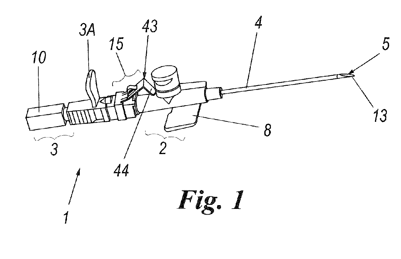
- a possible variant (shown in Figures 18 and 19) consists of inserting a ring or annular piece 90 into the cavity 18 of the part 15A of the protection element 15 within the portion 19 at a suitable distance from the aperture 19K.
- the annular piece 90 is hollow at 89 to enable the cannula 5 to slide within it.
- the central portion 88 of cavity 89 of annular piece 90 has a cross-section which is tenth microns greater than the nominal diameter of cannula 5, but less than the cross-section of the deformation 65 of the cannula 5.
- the deformation 65 cooperates by interference with the central portion 88 of the annular piece 90, said cooperation in no event enabling the needle to be withdrawn from said element 15.
- the cavity of the annular piece presents a pair of flared portions 87 facing and tapering towards each other.
- This flared portion has the same function as the part 70, described in relation to the preceding figures.
- the cavity of the annular piece 90 is symmetrical to enable said piece to be inserted into the cavity of the part 15A of the protection element 15 in both directions.
- the piece 90 can be fixed inside the cavity 18 of the part 15A of the element 15 by interference, by making its diameter greater than the inner diameter of the cavity 18.
- an undercut 78 in the form of an annular projection, for example see Figure 18
- the piece 90 can be glued to the interior of the element 15.
- the annular piece can be made of plastic, metal, ceramic material or any other material of adequate hardness and rigidity.
- the cannula needle of the invention is to be used.
- the needle is made to slide in the direction of the arrow F of that figure within the part 2 of the catheter needle 1 and into the cavity 17 of the element 15. This sliding takes place freely until the deformation 65 of the cannula 5 cooperates with the tapered end 19A ( Figure 7), this cooperation blocking the cannula at this latter. In this position the point 13 of the cannula 5 has been completely inserted into the portion 19 of said cavity.
- the elastic element 50 of the element 15 urges the portion 44 of the piece 43 above the aperture 19K of the portion 19 of the cavity 17 of the element 15, said portion 44 reclosing this aperture (and hence the part 16A of the member 16 of this element).
- the closure of said aperture prevents an operator being able to touch the needle and be injured. This is achieved totally automatically and safely.
- the portions 44 and 45 of the piece 43 are mutually inclined and non-perpendicular.
- the portions 44 and 45 form an acute angle between themselves, with the portion 44, after closure of the cavity, lying tightly resting on the aperture 19K.
- the aperture 19K can be formed not in a plane perpendicular to the axis W, but inclined to the axis W by an angle equal to the angle between the parts 44 and 45 of the piece 43. This aperture hence follows the inclination of the portion 44 for better closure.
- This figure shows a safety mechanism consisting of a triangular protrusion 106 positioned on the inner surface 107 of the part 44 of the piece 43 of the part 15B.
- this protrusion 106 irreversibly engages the surface 108 of the portion 19 of the part 15A.
- the triangular protrusion can be obtained by local deformation of the part 44 of said piece.
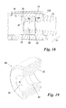
- a slot 132 (for example shown in Figure 16) provided in the portion 19 of the part 15A of the element 15.
- This slot is arranged to receive the part 44 of the piece 43 when positioned in front of the aperture 19K.
- the invention is hence of simple construction and use, and is of very low production cost.
- the protection element 15 is in the form of two separate portions 15A, 15B, it is simple to construct and to assemble with a cannula needle. The element can be produced separately from the cannula needle and then be connected to it, this allowing considerable flexibility from the industrial viewpoint.
- the two parts are easy to fit together using various industrial solutions, hence enabling the producer to choose the optimum solution.
- the two parts can be made of different materials, hence using materials suitable for the different functions which these parts have to perform.
- the element 15 can be torsionally locked onto the portion 2 of the cannula needle in a manner different from that described (for example, coupling by inserting pins into seats provided in the two components of the cannula needle) or the element 15 can be coupled to the portion 2 by external snap-engagement without providing the projection 22 cooperating with the seat 23.
- the protection element 15 could be coupled to the front portion 2 of the cannula needle 1, or the projection 22 cooperating with the seat 23 could be replaced by other mechanical couplings, already known to those operating in this sector.
- Figures 20 and 21 show other variants of the invention.
- the part 15B of the protection element 15 is defined by just the L-shaped piece 43, which is associated at its free end 43Z with the part 15A of said element.
- this end 43Z bent on itself to thicken it, is inserted into a seat 194 provided in a raised portion 195 formed on the side 41 of that part.
- the end 43Z presents the hole 96 and is arranged to cooperate with the pin 95 to secure it to the side 41 of the part 15A of the element 15.
- This pin is similar to that already described in relation to Figure 16.
Abstract
Description
- The present invention relates to a cannula needle or catheter needle in accordance with the introduction to the main claim.
- A cannula needle of the aforedescribed type comprises a first and a second portion which are mutually separable. The first portion comprises a catheter (usually of biocompatible plastic) to be introduced into a patient's vein, for example of the arm, and secured to a member to be fixed (in known manner) to the patient, for example to the patient's arm, in proximity to that vein. The second portion comprises a metal cannula used to cut the epidermis and the vein, to enable the catheter tube to be inserted into the vein. The cannula is associated with its own support element.
- When the catheter and cannula have been introduced into the vein, the cannula is extracted from the catheter and from the vein, and the second portion of the cannula needle is separated from the first. To this latter, or rather to the member carrying the catheter, there can then be connected any element, for example a tube, for transferring a medical product from a reservoir (for example a bag containing for example blood or nutrient fluid) into the vein.
- The cannula needle can be of one or two way type, depending on whether the first portion must be able to be connected to one or two of said elements for transferring a medical product into the vein.
- During the aforesaid separation of the needle of the second portion from the casing of the first portion it can happen that the medical operator or nurse assisting the patient may be accidentally pricked with the needle extracted from the catheter, with the possibility of contracting serious and dangerous infections.
- The Applicant is aware of cannula catheter needles provided with hollow protection elements for containing the point of the needle after it has been separated from the catheter, to prevent the operator being pricked by the needle. Such elements are described for example in
GB2292525 US5300045 and -
EP554841 - Said protection elements can comprise elastic means which position them on the cannula, or are simply associated with the support for the needle such that they reach the point of this latter when it is separated from the catheter.
- However, the known solutions do not always offer high reliability in use or are complicated and of considerable cost.
- Moreover, the presence of a protection device with a movable element which closes onto the cavity of this element (or within it) in the front of the cannula point can interfere with its movement in separating from the catheter, making it more difficult (for example because of rubbing between this movable element and the catheter). Again, if this protection element is completely inside the catheter until final separation (as in
US5300045 ), the operator may not be able to ascertain if the point of the cannula has been correctly protected or otherwise, on separation from the catheter. - An object of the present invention is to provide an improved catheter needle or cannula needle by which any risk of coming into contact with the cannula is safely and reliably eliminated, so ensuring the safety of those operators attending patients by adequately protecting them.
- Another object is to provide a cannula needle of the stated type which is simple to produce and use, is of small size, and the use of which does not negatively affect the cannula needle operability and/or its separation from the catheter.
- These and other objects which will be apparent to the expert of the art are attained by a cannula needle or catheter needle in accordance with the accompanying claims.
- The present invention will be more apparent from the accompanying drawings which are provided by way of non-limiting example and in which:
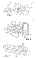
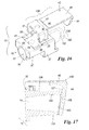
- Figure 1 is a perspective view of the overall catheter needle of the invention;
- Figure 2 is a perspective view of a detail of the catheter needle of the invention;
- Figure 3 is a detailed perspective view of a part of the invention;
- Figure 4 is a partial longitudinal section through the detail of Figure 3;
- Figure 5 is a partial perspective view of a stage during the use of the invention;
- Figure 6 is a perspective longitudinal sectional view of the invention during the separation of the needle from the catheter;
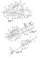
- Figure 7 is a longitudinal sectional side view of the invention during a further stage in its use;
- Figure 8 is a perspective longitudinal sectional view of the invention during a stage in which its two parts are undergoing separation;
- Figure 9 is a longitudinal section showing a further stage in the use of the invention;
- Figure 10 is a perspective view of the invention with its two parts separated;
- Figure 11 is an exploded perspective view of a specific embodiment of the invention;
- Figure 12 is a perspective view of the part of Figure 11 assembled;
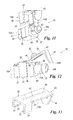
- Figure 13 is a perspective view of a different embodiment of a part of the invention;
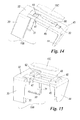
- Figures 14 and 15 are perspective views from different angles of a further variant of a part of the invention;
- Figure 16 is an exploded perspective view of a further embodiment of the invention;
- Figure 17 is a partial section through a further variant of the invention;
- Figure 18 is a section through a different internal configuration of the invention;
- Figure 19 is a detail of Figure 18; and
- Figures 20 and 21 show two further embodiments of the invention.
- With reference to said figures, a cannula needle is indicated overall by 1 and comprises two
portions first portion 2 being provided with a catheter 4 and the second portion comprising ausual cannula 5 to be inserted into the catheter 4 when the cannula has been introduced into patient's vein, and to be extracted from said catheter on termination of this introduction. - The
first portion 2 comprises a knownpart 8 to be fixed to the patient's body in proximity to the vein and comprises ausual member 9 for securing it to a conduit (not shown) connected to a container or receiver (such as a bag) containing for example blood or another fluid. - The
second portion 3 comprises ausual support 10 for thecannula 5. - In known manner, the
first portion 2 andsecond portion 3 are connected together on introducing the catheter 4 into the patient's vein, these portions being separable after this introduction to extract thecannula 5 from the catheter 4. The movement of thesecond portion 3 is facilitated by the presence of agripping member 3A associated with this portion. - To prevent an operator from being pricked by the
point 13 of thecannula 5, aprotection element 15 is provided interposed between theportions protection element 15 receives thepoint 13 of thecannula 5 when this is extracted from the catheter 4 and withdrawn from thesecond portion 2, said point being completely covered by theelement 15 to prevent its contact with said operator. - More specifically, the
element 15 comprises amember 16 hollow at 17 and traversed by thecannula 5 when this is inserted into the catheter 4. Thecavity 17 comprises afirst portion 18 close to thesecond portion 3 of thecannula needle 1 and asecond portion 19 provided in apart 16A of themember 16 to be inserted into the usual throughhole 20 in the first portion of thecannula needle 1 traversed by thecannula 5. Thesecond portion 19, open at 19K at the end of thepart 16A of themember 16 facing the catheter, is substantially of funnel shape and tapers towards thefirst portion 18 of thecavity 17 from which it is separated by its reduced-diameter end 19A. - To enable the
element 15 and thefirst portion 2 of thecannula needle 1 to be coupled together, thepart 16A of themember 16 of thiselement 15 comprises an outerannular projection 22 which fits into a correspondingannular seat 23 provided in thewall 20A of thehole 20 in thefirst portion 2 of the cannula needle - 1. In this manner, on introducing said
part 16A of themember 16 into thehole 20, when theprojection 22 fits into theseat 23 theelement 15 and saidfirst portion 2 are coupled together. - As shown in Figures 11 and 12, in a preferred embodiment of the invention, the
element 15 comprises substantially twoparts part 15B is of substantially inverted U-shape and comprises twoparallel arms transverse part 32. Each of these arms presents anend 33 facing the opposing arm to cooperate by snap engagement with acorresponding seat 35 provided in thepart 15A at the end of acorresponding groove 36 provide in aside 37 of said part. Thisgroove 36 houses acorresponding arm part 15B. Preferably, to achieve this snap engagement, the distance between thearms sides 37 of thepart 15A; in this manner, thearms part 15A and approach each other when theends 33 enter theseats 35 to hence lock thepart 15B on thepart 15A. - The
part 15B can be of plastic, metal, or metal clad with or co-moulded with plastic or with any other material suitable for the purpose. - The
part 15B can be mounted on thepart 15A by mechanical coupling different from the aforesaid snap engagement. - For example, as shown in Figure 16, the
ends 33 of the twoarms part 15B can face outwards. Thearms portion 15B become inserted into twoslots 99 opening, for example, into aside 41 perpendicular to thesides 37 of thepart 15A. Theends 33 engage thepart 15A such as to secure thepart 15B to it. Alternatively, theslots 99 could be present in thesides 37. - The
part 15B can present one ormore holes 96 in its rear (with reference to the position of theelement 15 relative to the catheter). Each hole couples to acorresponding pin 95 rising from theside 41 and having any shape. Eachpin 95 can present, at its free end, an undercut 79 to more securely fix thepart 15B to thepart 15A by its insertion into thehole 96. - A further method for fixing the
part 15B to thepart 15A is by gluing or welding the two components together. - The
part 15A, presenting thecavity 17, is of substantially parallelepiped shape and presents, projecting from aface 40 thereof, to which the sides are perpendicular, thepart 16A of themember 16. - The
transverse part 32 of thepart 15B is positioned on anupper side 41 perpendicular to thesides 37 and to theface 40. From this transverse part there projects a substantially L-shapedpiece 43 consequently presentingangled portions portion 45 is rigid with thepart 32 via ahinge 47 formed by weakening material integral with thepart 32 and thepiece 43. Finally, in the embodiment of Figures 1-12, above thispiece 43 there is a deformedelastic element 50 having afirst end 51 rigid with thepart 32 and asecond end 52 acting on theportion 45 of thepiece 43 and urging this latter towards thepart 16A of theelement 15. - On coupling the
element 15 and thefirst portion 2 of thecannula needle 1 together, theportion 44 is urged by theelastic element 50 to bear on saidfirst portion 2 and is maintained forcibly bearing against this latter. To improve this bearing, thefree end 44A of theportion 44 is rounded or otherwise shaped to obtain a form fit with saidportion 2. - The
elastic element 50 can be replaced by ametal component 15C having the same functions as the elastic element. Thismetal component 15C can have a shape suitable for securing to thepiece 43 of thepart 15B, or be simply awire 91 as shown in Figure 13. If themetal component 15C has a substantially rectangular shape, as shown in Figures 14 and 15, it can be secured to thepiece 43 of thepart 15B by insertion into two opposingseats 93 present at the end of a recess (or of a through slot) 98 present within theportion 45. Alternatively, thecomponent 15C can be inserted into two opposingpockets 92 present as projections on theparts part 15B. - The
component 15C can also be co-moulded with thepart 15B. - If the
piece 43 is made without any elastic element, as in Figure 16, and thepart 15B is mainly of L-shape (although thepart 32 and thearms part 15B and by the presence of thehinge 47. If thepart 15B is made of metal (or metal clad with plastic), the function of the elastic element can be obtained by a particular configuration of thepart 15B, for example bent about itself at the opposite end to theportion 44 and rigid with the hinge 47 (not shown). In this manner, its particular form offers preloading to thepart 15B, to prevent its yielding with time, with the risk of thepart 44 not coupling to theend 16A of thecomponent 15A, so non longer ensuring complete safety to the operator. - The
part 15B can also be made without any elastic element to automatically cause theportion 44 to rest on theend 19K of theelement 15A. In that case, after extracting the needle, the operator must activate the safety system with a finger, to bring theportion 44 into contact with theend 19K. - The
part 15A of theelement 15 also comprises anti-twist means for its coupling to theportion 2 of thecannula needle 1. These anti-twist means areprojections 55 extending from theface 40 of theportion 15A and arranged to cooperate withrecesses 60 provided in aflange 61 present in known manner at the end of saidportion 2. - In proximity to its
point 13 at a predefined distance therefrom, thecannula 5 comprises adeformation 65 formed on the outside of the cannula to increase its transverse dimension. The distance of this transverse deformation from thepoint 13 is less than the length of thesecond portion 19 of thecavity 17 of theelement 15 along the longitudinal axis W of this latter. On withdrawing the cannula from the catheter 4, this deformation cooperates by interference with thetapered end 19A of theportion 19, said cooperation preventing withdrawal of the needle from saidelement 15. Thistapered end 19A is preferably flared at 70 on that side facing thefirst portion 18 of thecavity 17, to hence enable the cannula to pass towards the catheter 4 when thecatheter needle 1 is being prepared for use, said inclination being such as to reduce the opening of thetapered end 19A in passing from theportion 18 to theportion 19 of thecavity 17. In this manner, the cannula can be introduced into the interior of theelement 15 and can emerge therefrom by being moved towards the catheter 4, whereas it cannot pass through thecavity 17 in the reverse direction to completely withdraw from theelement 15, as thedeformation 65 of thecannula 5 makes contact with thetapered end 19A of theportion 19 of this cavity and engages it. It should also be noted that to insert thecannula 5 into the catheter 4 without problems while allowing said engagement between thedeformation 65 and saidend 19A, the opening or diameter of this latter is a few hundredths of a millimetre greater than the diameter of thecannula 5; this latter diameter is greater than that of said end at saiddeformation 65 where this diameter (of the cannula) is greater than that of the opening in saidend 19A. - As an alternative to the
tapered end 19A of theportion 19, a possible variant (shown in Figures 18 and 19) consists of inserting a ring orannular piece 90 into thecavity 18 of thepart 15A of theprotection element 15 within theportion 19 at a suitable distance from theaperture 19K. Theannular piece 90 is hollow at 89 to enable thecannula 5 to slide within it. Thecentral portion 88 ofcavity 89 ofannular piece 90 has a cross-section which is tenth microns greater than the nominal diameter ofcannula 5, but less than the cross-section of thedeformation 65 of thecannula 5. On withdrawing the cannula from the catheter 4, thedeformation 65 cooperates by interference with thecentral portion 88 of theannular piece 90, said cooperation in no event enabling the needle to be withdrawn from saidelement 15. - The cavity of the annular piece presents a pair of flared
portions 87 facing and tapering towards each other. This flared portion has the same function as thepart 70, described in relation to the preceding figures. - The cavity of the
annular piece 90 is symmetrical to enable said piece to be inserted into the cavity of thepart 15A of theprotection element 15 in both directions. - The
piece 90 can be fixed inside thecavity 18 of thepart 15A of theelement 15 by interference, by making its diameter greater than the inner diameter of thecavity 18. Alternatively, an undercut 78 (in the form of an annular projection, for example see Figure 18) can be present inside thecavity 18 to maintain saidpiece 90 inside the cavity. Otherwise, thepiece 90 can be glued to the interior of theelement 15. - The annular piece can be made of plastic, metal, ceramic material or any other material of adequate hardness and rigidity.
- It will now be assumed that the cannula needle of the invention is to be used. After introducing the catheter 4 into the vein, the
cannula 5 is extracted from it. In a first stage, visible in Figure 6, the needle is made to slide in the direction of the arrow F of that figure within thepart 2 of thecatheter needle 1 and into thecavity 17 of theelement 15. This sliding takes place freely until thedeformation 65 of thecannula 5 cooperates with thetapered end 19A (Figure 7), this cooperation blocking the cannula at this latter. In this position thepoint 13 of thecannula 5 has been completely inserted into theportion 19 of said cavity. - Continuing the needle traction, the force applied in the direction of the arrow G of Figure 8 (parallel to the arrow F of Figure 6) causes the
annular projection 22 to detach from thecorresponding seat 23, with consequent separation of theelement 15 from thefirst portion 2 of thecannula needle 1. This element is hence detached from said portion. - On detachment, the
elastic element 50 of theelement 15 urges theportion 44 of thepiece 43 above theaperture 19K of theportion 19 of thecavity 17 of theelement 15, saidportion 44 reclosing this aperture (and hence thepart 16A of themember 16 of this element). As thepoint 13 of thecannula 5 is inserted into this portion and as the needle is stably coupled to theelement 15, the closure of said aperture prevents an operator being able to touch the needle and be injured. This is achieved totally automatically and safely. - To make undesirable reopening of the
cavity 17 more difficult, it is preferable to position theportions piece 43 mutually inclined and non-perpendicular. In this manner, theportions portion 44, after closure of the cavity, lying tightly resting on theaperture 19K. Likewise, theaperture 19K can be formed not in a plane perpendicular to the axis W, but inclined to the axis W by an angle equal to the angle between theparts piece 43. This aperture hence follows the inclination of theportion 44 for better closure. - To render the invention even more safe, mechanical couplings can be formed between the
portion 44 and the part 16a of themember 16 of theelement 15 to achieve snap closure of theaperture 19K, as shown in Figure 17. - This figure shows a safety mechanism consisting of a
triangular protrusion 106 positioned on theinner surface 107 of thepart 44 of thepiece 43 of thepart 15B. When thepart 44 covers theaperture 19K of thepiece 43, thisprotrusion 106 irreversibly engages thesurface 108 of theportion 19 of thepart 15A. - If the
piece 43 is of steel, the triangular protrusion can be obtained by local deformation of thepart 44 of said piece. - Safety can be further assured by a slot 132 (for example shown in Figure 16) provided in the
portion 19 of thepart 15A of theelement 15. This slot is arranged to receive thepart 44 of thepiece 43 when positioned in front of theaperture 19K. The invention is hence of simple construction and use, and is of very low production cost. In particular, as theprotection element 15 is in the form of twoseparate portions - The two parts are easy to fit together using various industrial solutions, hence enabling the producer to choose the optimum solution.
- Moreover, as the two parts are separate, they can be made of different materials, hence using materials suitable for the different functions which these parts have to perform.
- Various preferred embodiments of the invention have been described; others are however possible in the light of the aforegoing: for example, the
element 15 can be torsionally locked onto theportion 2 of the cannula needle in a manner different from that described (for example, coupling by inserting pins into seats provided in the two components of the cannula needle) or theelement 15 can be coupled to theportion 2 by external snap-engagement without providing theprojection 22 cooperating with theseat 23. Alternatively, theprotection element 15 could be coupled to thefront portion 2 of thecannula needle 1, or theprojection 22 cooperating with theseat 23 could be replaced by other mechanical couplings, already known to those operating in this sector. - Figures 20 and 21 show other variants of the invention. In these figures, in which parts corresponding to those of the already described figures are indicated by the same reference numerals, the
part 15B of theprotection element 15 is defined by just the L-shapedpiece 43, which is associated at its free end 43Z with thepart 15A of said element. - More specifically, in Figure 20 this end 43Z, bent on itself to thicken it, is inserted into a seat 194 provided in a raised portion 195 formed on the
side 41 of that part. Instead, in Figure 21 the end 43Z presents thehole 96 and is arranged to cooperate with thepin 95 to secure it to theside 41 of thepart 15A of theelement 15. This pin is similar to that already described in relation to Figure 16. - These variants are also to be considered as falling within the scope of the present document as defined by the accompanying claims.
Claims (25)
- A cannula needle or catheter needle (1) comprising a first portion (2) provided with a catheter (4) to be introduced into a vein and a second portion (3) provided with a cannula (5) which is inserted into the catheter (4) on introducing this latter into the vein, but is separable to be withdrawn from it after this introduction has taken place, the cannula (5) provided with a point (13) being associated with its own support (10) and being arranged to cooperate with a protection element (15) presenting a member (16) hollow (at 17) and open (at 19K) towards the catheter into which said cannula (5) is through-inserted, the cannula being locked in said element (15) when separated from the catheter (4), the protection element (15) being coupled to the first portion (2) and being interposed between this latter and said second portion (3), said protection element (15) being separable from the first portion (2) during the withdrawal of the cannula (5) from the catheter (4), said cannula (5) comprising coupling means (65) for securing it to said element (15) when its point (13), withdrawn from the catheter (4), is totally inserted into said cavity (17), this cooperation, together with the movement of the cannula (5), causing the protection element (15) to become detached from said first portion (2) of the cannula needle (1), the protection element (15) comprising a part (43) for closing its cavity (17) in which the cannula (5) is disposed on detaching said element (15) from the first portion (2) of the cannula needle (1), said protection element (15) being mechanically coupled to a part of the first portion (2) of said cannula needle (1), said closure part (43) being L-shaped and presenting angled portions (44, 45), a first (44) of these latter being arranged to position itself in front of the cavity (17) of the protection element (15) at the moment at which this latter separates from the first portion (2) of the cannula needle (1), characterised in that the part (43) forms at least part of a first portion (15B) of the protection element (15) which becomes connected to a second portion (15A) in which the internal cavity (17) of said element is present.
- A cannula needle as claimed in claim 1, characterised in that said L-shaped part (43) defines said first portion (15B) of the protection element and is directly secured to the second portion (15A) of this latter.
- A cannula needle as claimed in claim 2, characterised in that said L-shaped part (43) is an I-shaped strip and is secured at a free end to a retention element associated with the second portion (15A) of said protection element.
- A cannula needle as claimed in claim 1, characterised in that the first portion (15B) is substantially of inverted U-shape and comprises two arms (30, 31) arranged to connect to the second portion (15A) by mechanical coupling, said arms being connected together by a transverse part (32) from which the L-shaped part (43) projects.
- A cannula needle as claimed in claim 4, characterised in that said arms (30, 31) present ends (33) arranged to snap-engage respective seats (35, 99) provided inn the second portion (15A) of the protection element.
- A cannula needle as claimed in claim 4, characterised in that the first portion (44) of the L-shaped piece (43) is elastically loaded and presents an end (44A) which engages as a form fit with the exterior of the first portion (2) of the cannula needle (1) on which this end presses when the protection element is rigid with said first portion (2) of the cannula needle (1).
- A cannula needle as claimed in claim 1, characterised by comprising means (106) for mechanical connection between the first portion (44) of the part (43) and that part (16A) of the member (16) of the protection element (15) provided with the aperture (19K), said means (106) being associated with an internal surface (107) of said portion (44) and cooperating in closure with the internal surface (108) such as to maintain said portion (44) closed onto said aperture.
- A cannula needle as claimed in claim 1, characterised in that the portions (44, 45) of the part (43) form a contained acute angle.
- A cannula needle as claimed in claim 1, characterised in that the protection element (15) is mechanically coupled to an internal part (20) of said first portion (2).
- A cannula needle as claimed in claim 9, characterised in that the member (16) of the protection element (15) presents a part (16A) inserted into the usual through hole (20) of said first portion (2) of the cannula needle, said part (16A) comprising coupling means (22) and restraining counter-means (23) provided in said hole (20).
- A cannula needle as claimed in claim 10, characterised in that the coupling means are an annular projection (22) provided on the outside of the part (16A) of the member (16) of the protection element (15), the counter-means being a seat (23) provided within the wall (20A) of said through hole (20).
- A cannula needle as claimed in claim 10, characterised in that the cavity (17) of said member (16) comprises two consecutive portions (18, 19), the first portion (18) facing the second portion (3) of the cannula needle, the second portion (19) being tapered towards the first and terminating with a reduced diameter end (19A) separating the second portion (19) from the first (18), the second portion having an aperture (19K) at that end (16A) of the member (16) inserted into the through hole (20) of the second portion (2) of the cannula needle (1).
- A cannula needle as claimed in claim 12, characterised in that the reduced diameter end (19A) is defined by an annular piece (90) internally hollow (at 89) and presenting flared portions (87) which taper towards each other.
- A cannula needle as claimed in claim 13, characterised in that the annular piece (90) is fixed within the protection element.
- A cannula needle as claimed in claim 1, characterised in that the closure piece (43) of the first portion (15B) of the protection element (15) is elastically urged to bring the first (44) of its portions in front of the cavity (17) of the protection element (15), when in this position it being positioned in front of the aperture (19K) of said cavity (17), facing the first portion (2) of the cannula needle (1).
- A cannula needle as claimed in claim 15, characterised in that the protection element (15) comprises an elastic element (50, 15C) rigid with the first portion (15B) of the protection element (15) and having a second end (52) acting on the part (45) of the L-shaped piece (43) to urge the first portion (44) of this latter in front of the cavity (17).
- A cannula needle as claimed in claim 1, characterised in that the closure piece (43) of the first portion (15B) of the protection element (15) is elastically urged to bring the first (44) of its portions (44, 45) into a slot (132) provided in the second portion (15A) and opening into the cavity (17) of this latter.
- A cannula needle as claimed in claim 15, characterised in that the elastic element (50) is integral with the first portion (15B) of the protection element.
- A cannula needle as claimed in claim 15, characterised in that the elastic element is a component (15C) independently coupled to and rigid with the first portion (15B) of said element so as to act on the L-shaped piece (43) of this latter.
- A cannula needle as claimed in claim 18, characterised in that said elastic element is at least partially inserted in the seat and/or housings (93, 98) of said first portion (15B).
- A cannula needle as claimed in claim 1, characterised in that the aperture (19K) in that part (16A) of the member (16) facing the catheter lies in a plane cutting the axis (W), this aperture (19K) being inclined to the axis (W) by an angle equal to the angle between the parts (44, 45) of the piece (43).
- A cannula needle as claimed in claim 1, characterised in that anti-twist means (55) are provided on the protection element (15) to cooperate with counter-means (60) of the first portion (2) of the cannula needle to prevent relative torsional movements between this latter and said element.
- A cannula needle as claimed in claim 22, characterised in that the anti-twist means are at least one arm (55) projecting from the protection element and arranged to cooperate with a recess (60) provided in an end flange (61) of said first portion (2) of the cannula needle (1).
- A cannula needle as claimed in claim 23, characterised in that the anti-twist means comprising the arm (55) present a snap coupling to couple the protection element (15) to the front portion (2) of said cannula needle (1).
- A cannula needle as claimed in claim 22, characterised in that the anti-twist means are pins which become inserted into seats provided in the first and in the second portion (2, 3) of the cannula needle.
Applications Claiming Priority (1)
| Application Number | Priority Date | Filing Date | Title |
|---|---|---|---|
| ITMI20062127 ITMI20062127A1 (en) | 2006-11-07 | 2006-11-07 | SAFETY TUBE NEEDLE WITH AGING PROTECTION ELEMENT AUTOMATICALLY ACTIVATED WITH THE LOCKING OF THIS LAST FROM THE CATHETER |
Publications (2)
| Publication Number | Publication Date |
|---|---|
| EP1920796A1 true EP1920796A1 (en) | 2008-05-14 |
| EP1920796B1 EP1920796B1 (en) | 2012-08-29 |
Family
ID=38109664
Family Applications (1)
| Application Number | Title | Priority Date | Filing Date |
|---|---|---|---|
| EP20070119573 Active EP1920796B1 (en) | 2006-11-07 | 2007-10-30 | Safety cannula needle with needle protection element activated automaticly on detaching the needle from the catheter |
Country Status (4)
| Country | Link |
|---|---|
| EP (1) | EP1920796B1 (en) |
| ES (1) | ES2392627T3 (en) |
| IT (1) | ITMI20062127A1 (en) |
| PT (1) | PT1920796E (en) |
Cited By (6)
| Publication number | Priority date | Publication date | Assignee | Title |
|---|---|---|---|---|
| JP2015530150A (en) * | 2012-08-27 | 2015-10-15 | インジェクティメッド,インク. | Needle guard |
| US9440052B2 (en) | 2011-02-28 | 2016-09-13 | Injectimed, Inc. | Needle guard |
| US9610403B2 (en) | 2011-02-28 | 2017-04-04 | Injectimed, Inc. | Needle guard |
| JP2018023587A (en) * | 2016-08-10 | 2018-02-15 | ニプロ株式会社 | Indwelling needle assembly |
| EP3283146A4 (en) * | 2015-04-09 | 2019-02-27 | Vigmed AB | Needle tip shielding device and catheter hub therefore |
| WO2019123120A1 (en) * | 2017-12-18 | 2019-06-27 | Sol-Millennium Swiss R&D Center Sa | Improved safety catheter needle |
Families Citing this family (1)
| Publication number | Priority date | Publication date | Assignee | Title |
|---|---|---|---|---|
| GB2529270B (en) | 2015-01-02 | 2016-07-27 | Becton Dickinson Co | Safety intravenous catheter with friction-based retention and disabling feature |
Citations (4)
| Publication number | Priority date | Publication date | Assignee | Title |
|---|---|---|---|---|
| WO1992008502A1 (en) * | 1990-11-08 | 1992-05-29 | Mbo Laboratories, Inc. | Catheter assembly having safety means |
| US5300045A (en) * | 1993-04-14 | 1994-04-05 | Plassche Jr Walter M | Interventional needle having an automatically capping stylet |
| GB2292525A (en) * | 1994-08-24 | 1996-02-28 | Sterimatic Holdings Ltd | Catheter Unit having a Needle Locking Device and a Releasable Catheter Hub |
| DE20218551U1 (en) * | 2002-11-29 | 2004-04-08 | B. Braun Melsungen Ag | Injection or infusion needle protection unit, comprises a needle holder with a protective element for the needle tip, and a push sleeve and cover element |
-
2006
- 2006-11-07 IT ITMI20062127 patent/ITMI20062127A1/en unknown
-
2007
- 2007-10-30 EP EP20070119573 patent/EP1920796B1/en active Active
- 2007-10-30 PT PT07119573T patent/PT1920796E/en unknown
- 2007-10-30 ES ES07119573T patent/ES2392627T3/en active Active
Patent Citations (4)
| Publication number | Priority date | Publication date | Assignee | Title |
|---|---|---|---|---|
| WO1992008502A1 (en) * | 1990-11-08 | 1992-05-29 | Mbo Laboratories, Inc. | Catheter assembly having safety means |
| US5300045A (en) * | 1993-04-14 | 1994-04-05 | Plassche Jr Walter M | Interventional needle having an automatically capping stylet |
| GB2292525A (en) * | 1994-08-24 | 1996-02-28 | Sterimatic Holdings Ltd | Catheter Unit having a Needle Locking Device and a Releasable Catheter Hub |
| DE20218551U1 (en) * | 2002-11-29 | 2004-04-08 | B. Braun Melsungen Ag | Injection or infusion needle protection unit, comprises a needle holder with a protective element for the needle tip, and a push sleeve and cover element |
Cited By (12)
| Publication number | Priority date | Publication date | Assignee | Title |
|---|---|---|---|---|
| US9440052B2 (en) | 2011-02-28 | 2016-09-13 | Injectimed, Inc. | Needle guard |
| US9610403B2 (en) | 2011-02-28 | 2017-04-04 | Injectimed, Inc. | Needle guard |
| US9844624B2 (en) | 2011-02-28 | 2017-12-19 | Injectimed, Inc. | Needle guard |
| US9987423B2 (en) | 2011-02-28 | 2018-06-05 | Injectimed, Inc. | Needle guard |
| US10525197B2 (en) | 2011-02-28 | 2020-01-07 | Injectimed, Inc. | Needle guard |
| US11344671B2 (en) | 2011-02-28 | 2022-05-31 | Injectimed, Inc. | Needle guard |
| JP2015530150A (en) * | 2012-08-27 | 2015-10-15 | インジェクティメッド,インク. | Needle guard |
| EP3283146A4 (en) * | 2015-04-09 | 2019-02-27 | Vigmed AB | Needle tip shielding device and catheter hub therefore |
| US11202887B2 (en) | 2015-04-09 | 2021-12-21 | Vigmed Ab | Needle tip shielding device and catheter hub therefore |
| JP2018023587A (en) * | 2016-08-10 | 2018-02-15 | ニプロ株式会社 | Indwelling needle assembly |
| WO2019123120A1 (en) * | 2017-12-18 | 2019-06-27 | Sol-Millennium Swiss R&D Center Sa | Improved safety catheter needle |
| US11135404B2 (en) | 2017-12-18 | 2021-10-05 | Sol-Millennium Swiss R&D Center Sa | Safety catheter needle |
Also Published As
| Publication number | Publication date |
|---|---|
| ES2392627T3 (en) | 2012-12-12 |
| ITMI20062127A1 (en) | 2008-05-08 |
| EP1920796B1 (en) | 2012-08-29 |
| PT1920796E (en) | 2012-10-25 |
Similar Documents
| Publication | Publication Date | Title |
|---|---|---|
| EP1920796B1 (en) | Safety cannula needle with needle protection element activated automaticly on detaching the needle from the catheter | |
| KR100787691B1 (en) | Protector and storage needle assembly | |
| US10369280B2 (en) | Indwelling needle assembly | |
| EP2214754B1 (en) | Catheter insertion device with automatic safety barrier | |
| EP2736577B1 (en) | Needle tip protector assembly for safety iv catheter assembly | |
| EP2745769B1 (en) | Blood collection assembly | |
| US6357589B2 (en) | Packaging of catheter products | |
| EP2764885A1 (en) | Indwelling catheter | |
| JP7174353B2 (en) | Valved needle assembly and indwelling needle assembly | |
| KR20130086945A (en) | Tip protector for a safety catheter | |
| WO1995019193A1 (en) | Retractable venipuncture catheter needle and receptacle | |
| US20190192825A1 (en) | Passive release safety shield for catheter assemblies and related methods | |
| EP3260157B1 (en) | Indwelling needle assembly | |
| JP6089638B2 (en) | Indwelling needle assembly | |
| AU2014369757B2 (en) | Safety needle assemblies and related methods | |
| CN111093749B (en) | Improved medical device with elastically retractable safety needle | |
| JP2018117807A (en) | Indwelling needle assembly | |
| EP2450070B1 (en) | Blood collection set, sampling holder, and needle cover for preventing erroneous needle insertion | |
| CN113631214B (en) | Improved coupling between a telescoping needle shield and a catheter adapter | |
| RU2575312C2 (en) | Safety needle configuration and assembly | |
| US20230226312A1 (en) | Intravenous cannula | |
| JP7403760B2 (en) | medical connectors | |
| US20230226323A1 (en) | Intravenous cannula | |
| CN115835898A (en) | Catheter instrument comprising a catheter assembly with a catheter hub, a high pressure clamp and a needle shield, method of assembling the catheter instrument | |
| CN112057723A (en) | Safety catheter needle |
Legal Events
| Date | Code | Title | Description |
|---|---|---|---|
| PUAI | Public reference made under article 153(3) epc to a published international application that has entered the european phase |
Free format text: ORIGINAL CODE: 0009012 |
|
| AK | Designated contracting states |
Kind code of ref document: A1 Designated state(s): AT BE BG CH CY CZ DE DK EE ES FI FR GB GR HU IE IS IT LI LT LU LV MC MT NL PL PT RO SE SI SK TR |
|
| AX | Request for extension of the european patent |
Extension state: AL BA HR MK RS |
|
| 17P | Request for examination filed |
Effective date: 20081113 |
|
| AKX | Designation fees paid |
Designated state(s): AT BE BG CH CY CZ DE DK EE ES FI FR GB GR HU IE IS IT LI LT LU LV MC MT NL PL PT RO SE SI SK TR |
|
| GRAP | Despatch of communication of intention to grant a patent |
Free format text: ORIGINAL CODE: EPIDOSNIGR1 |
|
| GRAS | Grant fee paid |
Free format text: ORIGINAL CODE: EPIDOSNIGR3 |
|
| GRAA | (expected) grant |
Free format text: ORIGINAL CODE: 0009210 |
|
| AK | Designated contracting states |
Kind code of ref document: B1 Designated state(s): AT BE BG CH CY CZ DE DK EE ES FI FR GB GR HU IE IS IT LI LT LU LV MC MT NL PL PT RO SE SI SK TR |
|
| REG | Reference to a national code |
Ref country code: GB Ref legal event code: FG4D |
|
| REG | Reference to a national code |
Ref country code: CH Ref legal event code: EP |
|
| REG | Reference to a national code |
Ref country code: AT Ref legal event code: REF Ref document number: 572719 Country of ref document: AT Kind code of ref document: T Effective date: 20120915 |
|
| REG | Reference to a national code |
Ref country code: IE Ref legal event code: FG4D |
|
| REG | Reference to a national code |
Ref country code: DE Ref legal event code: R096 Ref document number: 602007025080 Country of ref document: DE Effective date: 20121025 Ref country code: PT Ref legal event code: SC4A Free format text: AVAILABILITY OF NATIONAL TRANSLATION Effective date: 20121016 |
|
| REG | Reference to a national code |
Ref country code: ES Ref legal event code: FG2A Ref document number: 2392627 Country of ref document: ES Kind code of ref document: T3 Effective date: 20121212 |
|
| REG | Reference to a national code |
Ref country code: AT Ref legal event code: MK05 Ref document number: 572719 Country of ref document: AT Kind code of ref document: T Effective date: 20120829 |
|
| REG | Reference to a national code |
Ref country code: NL Ref legal event code: VDEP Effective date: 20120829 |
|
| REG | Reference to a national code |
Ref country code: LT Ref legal event code: MG4D Effective date: 20120829 |
|
| PG25 | Lapsed in a contracting state [announced via postgrant information from national office to epo] |
Ref country code: LT Free format text: LAPSE BECAUSE OF FAILURE TO SUBMIT A TRANSLATION OF THE DESCRIPTION OR TO PAY THE FEE WITHIN THE PRESCRIBED TIME-LIMIT Effective date: 20120829 Ref country code: AT Free format text: LAPSE BECAUSE OF FAILURE TO SUBMIT A TRANSLATION OF THE DESCRIPTION OR TO PAY THE FEE WITHIN THE PRESCRIBED TIME-LIMIT Effective date: 20120829 Ref country code: FI Free format text: LAPSE BECAUSE OF FAILURE TO SUBMIT A TRANSLATION OF THE DESCRIPTION OR TO PAY THE FEE WITHIN THE PRESCRIBED TIME-LIMIT Effective date: 20120829 Ref country code: CY Free format text: LAPSE BECAUSE OF FAILURE TO SUBMIT A TRANSLATION OF THE DESCRIPTION OR TO PAY THE FEE WITHIN THE PRESCRIBED TIME-LIMIT Effective date: 20120829 Ref country code: IS Free format text: LAPSE BECAUSE OF FAILURE TO SUBMIT A TRANSLATION OF THE DESCRIPTION OR TO PAY THE FEE WITHIN THE PRESCRIBED TIME-LIMIT Effective date: 20121229 |
|
| PG25 | Lapsed in a contracting state [announced via postgrant information from national office to epo] |
Ref country code: BE Free format text: LAPSE BECAUSE OF FAILURE TO SUBMIT A TRANSLATION OF THE DESCRIPTION OR TO PAY THE FEE WITHIN THE PRESCRIBED TIME-LIMIT Effective date: 20120829 Ref country code: SE Free format text: LAPSE BECAUSE OF FAILURE TO SUBMIT A TRANSLATION OF THE DESCRIPTION OR TO PAY THE FEE WITHIN THE PRESCRIBED TIME-LIMIT Effective date: 20120829 Ref country code: SI Free format text: LAPSE BECAUSE OF FAILURE TO SUBMIT A TRANSLATION OF THE DESCRIPTION OR TO PAY THE FEE WITHIN THE PRESCRIBED TIME-LIMIT Effective date: 20120829 Ref country code: GR Free format text: LAPSE BECAUSE OF FAILURE TO SUBMIT A TRANSLATION OF THE DESCRIPTION OR TO PAY THE FEE WITHIN THE PRESCRIBED TIME-LIMIT Effective date: 20121130 Ref country code: LV Free format text: LAPSE BECAUSE OF FAILURE TO SUBMIT A TRANSLATION OF THE DESCRIPTION OR TO PAY THE FEE WITHIN THE PRESCRIBED TIME-LIMIT Effective date: 20120829 |
|
| PG25 | Lapsed in a contracting state [announced via postgrant information from national office to epo] |
Ref country code: DK Free format text: LAPSE BECAUSE OF FAILURE TO SUBMIT A TRANSLATION OF THE DESCRIPTION OR TO PAY THE FEE WITHIN THE PRESCRIBED TIME-LIMIT Effective date: 20120829 Ref country code: NL Free format text: LAPSE BECAUSE OF FAILURE TO SUBMIT A TRANSLATION OF THE DESCRIPTION OR TO PAY THE FEE WITHIN THE PRESCRIBED TIME-LIMIT Effective date: 20120829 Ref country code: RO Free format text: LAPSE BECAUSE OF FAILURE TO SUBMIT A TRANSLATION OF THE DESCRIPTION OR TO PAY THE FEE WITHIN THE PRESCRIBED TIME-LIMIT Effective date: 20120829 Ref country code: CZ Free format text: LAPSE BECAUSE OF FAILURE TO SUBMIT A TRANSLATION OF THE DESCRIPTION OR TO PAY THE FEE WITHIN THE PRESCRIBED TIME-LIMIT Effective date: 20120829 Ref country code: EE Free format text: LAPSE BECAUSE OF FAILURE TO SUBMIT A TRANSLATION OF THE DESCRIPTION OR TO PAY THE FEE WITHIN THE PRESCRIBED TIME-LIMIT Effective date: 20120829 |
|
| PG25 | Lapsed in a contracting state [announced via postgrant information from national office to epo] |
Ref country code: SK Free format text: LAPSE BECAUSE OF FAILURE TO SUBMIT A TRANSLATION OF THE DESCRIPTION OR TO PAY THE FEE WITHIN THE PRESCRIBED TIME-LIMIT Effective date: 20120829 Ref country code: PL Free format text: LAPSE BECAUSE OF FAILURE TO SUBMIT A TRANSLATION OF THE DESCRIPTION OR TO PAY THE FEE WITHIN THE PRESCRIBED TIME-LIMIT Effective date: 20120829 Ref country code: MC Free format text: LAPSE BECAUSE OF NON-PAYMENT OF DUE FEES Effective date: 20121031 |
|
| REG | Reference to a national code |
Ref country code: CH Ref legal event code: PL |
|
| PLBE | No opposition filed within time limit |
Free format text: ORIGINAL CODE: 0009261 |
|
| STAA | Information on the status of an ep patent application or granted ep patent |
Free format text: STATUS: NO OPPOSITION FILED WITHIN TIME LIMIT |
|
| GBPC | Gb: european patent ceased through non-payment of renewal fee |
Effective date: 20121129 |
|
| PG25 | Lapsed in a contracting state [announced via postgrant information from national office to epo] |
Ref country code: BG Free format text: LAPSE BECAUSE OF FAILURE TO SUBMIT A TRANSLATION OF THE DESCRIPTION OR TO PAY THE FEE WITHIN THE PRESCRIBED TIME-LIMIT Effective date: 20121129 Ref country code: DE Free format text: LAPSE BECAUSE OF NON-PAYMENT OF DUE FEES Effective date: 20130501 Ref country code: CH Free format text: LAPSE BECAUSE OF NON-PAYMENT OF DUE FEES Effective date: 20121031 Ref country code: LI Free format text: LAPSE BECAUSE OF NON-PAYMENT OF DUE FEES Effective date: 20121031 |
|
| REG | Reference to a national code |
Ref country code: IE Ref legal event code: MM4A |
|
| 26N | No opposition filed |
Effective date: 20130530 |
|
| REG | Reference to a national code |
Ref country code: DE Ref legal event code: R119 Ref document number: 602007025080 Country of ref document: DE Effective date: 20130501 |
|
| PG25 | Lapsed in a contracting state [announced via postgrant information from national office to epo] |
Ref country code: IE Free format text: LAPSE BECAUSE OF NON-PAYMENT OF DUE FEES Effective date: 20121030 |
|
| PG25 | Lapsed in a contracting state [announced via postgrant information from national office to epo] |
Ref country code: GB Free format text: LAPSE BECAUSE OF NON-PAYMENT OF DUE FEES Effective date: 20121129 Ref country code: MT Free format text: LAPSE BECAUSE OF FAILURE TO SUBMIT A TRANSLATION OF THE DESCRIPTION OR TO PAY THE FEE WITHIN THE PRESCRIBED TIME-LIMIT Effective date: 20120829 |
|
| PG25 | Lapsed in a contracting state [announced via postgrant information from national office to epo] |
Ref country code: TR Free format text: LAPSE BECAUSE OF FAILURE TO SUBMIT A TRANSLATION OF THE DESCRIPTION OR TO PAY THE FEE WITHIN THE PRESCRIBED TIME-LIMIT Effective date: 20120829 |
|
| PG25 | Lapsed in a contracting state [announced via postgrant information from national office to epo] |
Ref country code: LU Free format text: LAPSE BECAUSE OF NON-PAYMENT OF DUE FEES Effective date: 20121030 |
|
| PG25 | Lapsed in a contracting state [announced via postgrant information from national office to epo] |
Ref country code: HU Free format text: LAPSE BECAUSE OF FAILURE TO SUBMIT A TRANSLATION OF THE DESCRIPTION OR TO PAY THE FEE WITHIN THE PRESCRIBED TIME-LIMIT Effective date: 20071030 |
|
| REG | Reference to a national code |
Ref country code: FR Ref legal event code: PLFP Year of fee payment: 9 |
|
| REG | Reference to a national code |
Ref country code: FR Ref legal event code: PLFP Year of fee payment: 10 |
|
| REG | Reference to a national code |
Ref country code: FR Ref legal event code: PLFP Year of fee payment: 11 |
|
| REG | Reference to a national code |
Ref country code: ES Ref legal event code: PC2A Owner name: PIKDARE S.R.L. Effective date: 20180403 |
|
| REG | Reference to a national code |
Ref country code: FR Ref legal event code: PLFP Year of fee payment: 12 |
|
| REG | Reference to a national code |
Ref country code: FR Ref legal event code: TP Owner name: PIKDARE S.R.L., IT Effective date: 20180919 |
|
| REG | Reference to a national code |
Ref country code: ES Ref legal event code: PC2A Owner name: PIKDARE-SOCIETA' PER AZIONI Effective date: 20221116 |
|
| P01 | Opt-out of the competence of the unified patent court (upc) registered |
Effective date: 20230602 |
|
| P02 | Opt-out of the competence of the unified patent court (upc) changed |
Effective date: 20230822 |
|
| PGFP | Annual fee paid to national office [announced via postgrant information from national office to epo] |
Ref country code: ES Payment date: 20231222 Year of fee payment: 17 |
|
| PGFP | Annual fee paid to national office [announced via postgrant information from national office to epo] |
Ref country code: PT Payment date: 20231019 Year of fee payment: 17 Ref country code: IT Payment date: 20231027 Year of fee payment: 17 Ref country code: FR Payment date: 20231023 Year of fee payment: 17 |