EP1921996B1 - Broadband acoustic sensor for an implantable medical device - Google Patents
Broadband acoustic sensor for an implantable medical device Download PDFInfo
- Publication number
- EP1921996B1 EP1921996B1 EP06813763.7A EP06813763A EP1921996B1 EP 1921996 B1 EP1921996 B1 EP 1921996B1 EP 06813763 A EP06813763 A EP 06813763A EP 1921996 B1 EP1921996 B1 EP 1921996B1
- Authority
- EP
- European Patent Office
- Prior art keywords
- sensor
- compartment
- imd
- acoustic sensor
- diaphragm
- Prior art date
- Legal status (The legal status is an assumption and is not a legal conclusion. Google has not performed a legal analysis and makes no representation as to the accuracy of the status listed.)
- Not-in-force
Links
Images


Classifications
-
- A—HUMAN NECESSITIES
- A61—MEDICAL OR VETERINARY SCIENCE; HYGIENE
- A61B—DIAGNOSIS; SURGERY; IDENTIFICATION
- A61B7/00—Instruments for auscultation
- A61B7/02—Stethoscopes
- A61B7/023—Stethoscopes for introduction into the body, e.g. into the oesophagus
-
- A—HUMAN NECESSITIES
- A61—MEDICAL OR VETERINARY SCIENCE; HYGIENE
- A61N—ELECTROTHERAPY; MAGNETOTHERAPY; RADIATION THERAPY; ULTRASOUND THERAPY
- A61N1/00—Electrotherapy; Circuits therefor
- A61N1/18—Applying electric currents by contact electrodes
- A61N1/32—Applying electric currents by contact electrodes alternating or intermittent currents
- A61N1/36—Applying electric currents by contact electrodes alternating or intermittent currents for stimulation
- A61N1/372—Arrangements in connection with the implantation of stimulators
- A61N1/375—Constructional arrangements, e.g. casings
- A61N1/37512—Pacemakers
-
- A—HUMAN NECESSITIES
- A61—MEDICAL OR VETERINARY SCIENCE; HYGIENE
- A61N—ELECTROTHERAPY; MAGNETOTHERAPY; RADIATION THERAPY; ULTRASOUND THERAPY
- A61N1/00—Electrotherapy; Circuits therefor
- A61N1/18—Applying electric currents by contact electrodes
- A61N1/32—Applying electric currents by contact electrodes alternating or intermittent currents
- A61N1/36—Applying electric currents by contact electrodes alternating or intermittent currents for stimulation
- A61N1/362—Heart stimulators
- A61N1/365—Heart stimulators controlled by a physiological parameter, e.g. heart potential
- A61N1/36514—Heart stimulators controlled by a physiological parameter, e.g. heart potential controlled by a physiological quantity other than heart potential, e.g. blood pressure
- A61N1/36542—Heart stimulators controlled by a physiological parameter, e.g. heart potential controlled by a physiological quantity other than heart potential, e.g. blood pressure controlled by body motion, e.g. acceleration
-
- A—HUMAN NECESSITIES
- A61—MEDICAL OR VETERINARY SCIENCE; HYGIENE
- A61N—ELECTROTHERAPY; MAGNETOTHERAPY; RADIATION THERAPY; ULTRASOUND THERAPY
- A61N1/00—Electrotherapy; Circuits therefor
- A61N1/18—Applying electric currents by contact electrodes
- A61N1/32—Applying electric currents by contact electrodes alternating or intermittent currents
- A61N1/36—Applying electric currents by contact electrodes alternating or intermittent currents for stimulation
- A61N1/372—Arrangements in connection with the implantation of stimulators
- A61N1/375—Constructional arrangements, e.g. casings
- A61N1/3752—Details of casing-lead connections
- A61N1/3754—Feedthroughs
Definitions
- the present invention relates to sensors used in combination with a cardiac function management device such as a heart pacemaker or defibrillator to monitor and control the rhythm of the heart.
- a cardiac function management device such as a heart pacemaker or defibrillator to monitor and control the rhythm of the heart.
- the present invention more particularly relates to sensors used to detect heart sounds and methods of modifying therapy based on these heart sounds.
- Cardiac function management systems are used to treat heart arrhythmias. Pacemaker systems are commonly implanted in patients to treat bradycardia (i.e., abnormally slow heart rate).
- a pacemaker system includes an implantable pulse generator and leads, which form the electrical connection between the implantable pulse generator and the heart.
- An implantable cardioverter defibrillator (“ICD”) is used to treat tachycardia (i.e., abnormally rapid heart rate).
- An ICD also includes a pulse generator and leads that deliver electrical energy to the heart.
- ICD implantable cardioverter defibrillator
- An ICD also includes a pulse generator and leads that deliver electrical energy to the heart.
- CTR cardiac resynchronization therapy
- biventricular pacing is an emerging treatment for heart failure, which involves stimulation of both the right and the left ventricles to increase hemodynamic efficiency and cardiac output.
- the beating heart produces a series of auditory vibrations (i.e., heart sounds) that can be characterized by intensity, frequency, quality, and timing with respect to the cardiac cycle.
- heart sounds Two of the normal heart sounds, commonly known as the S1 and S2 sounds, relate to closing of various heart valves. Specifically, the S1 sound is generated by the closing of the mitral and tricuspid valves and thus generally correlates to the onset of ventricular systole, and the S2 sound is generated by the closing of the pulmomary and aortic valves and thus generally correlates to the onset of ventricular diastole.
- These sounds may also indicate problems or abnormalities in the pumping process, such as for example a murmur or mitral regurgitation.
- EP 1 151 719 A2 discloses an apparatus for monitoring the condition of a heart failure patient.
- An implantable or other ambulatory monitor senses the patient's respiratory patterns to identify the presence of periodic breathing, medical changes of the thorax due to breathing are detected and this data is used to recognize hyperventilation and apnea or hypoventilation.
- Mechanical changes of the thorax are detected using an ultrasound transducer or an intrathoracic pressure transducer.
- the implantable or other ambulatory device is used with one or a plurality of sensors, electronic circuitry that is coupled to the sensors and processes their output, a transmitter/receiver for telemetrically conveying information between the monitor and an external unit, and a patient alert which notifies the patient if medical attention should be sought.
- EP 0 798 016 A2 describes a pacemaker system which utilizes a pressure sensor positioned in the implantable pacemaker. Relative pressure signals ⁇ are transmitted from the patient's heart through the lumen of a pacing lead, which signals are communicated to the pressure sensor mounted either within the pacemaker connector block, or within the encapsulated pacemaker can.
- the pacemaker-mounted sensor receives detectable pressure variations representative of heart movement, and is able to transform such relative pressure signals into parameter signals for use in controlling a pacemaker operating variable such as pacing rate.
- the present invention relates to an implantable medical device (IMID) including a pulse generator having a housing and a compartment which defines an isolated cavity. A compartment diaphragm is disposed over and encloses the cavity. An acoustic sensor is adapted to sense chest sounds and generate a signal. A control circuit disposed within the pulse generator is operatively coupled to the acoustic sensor and is adapted to receive the signal.
- IMID implantable medical device
- the cavity is hermetically sealed and bounded by back wall, and the compartment diaphragm has a resonance frequency greater than about 20 kHz.
- the acoustic sensor has a sensor diaphragm and is adapted to sense chest sounds having a frequency from about 10 Hz to about 20 kHz.
- the sensor is disposed between the compartment diaphragm and the back wall such that a space is maintained between the sensor diaphragm and the compartment diaphragm, the space being filled with a fluid or gel, which has an independence that generally matches the impedance of the human body.
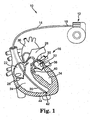
- FIG. 1 is a perspective view of an implantable medical device (IMD) or cardiac function management (CFM) system 10.
- the system 10 includes a pulse generator 12 and a cardiac lead 14.
- the lead 14 operates to convey electrical signals between the heart 16 and the pulse generator 12.
- a proximal end 18 of the lead 14 is coupled to the pulse generator 12 and a distal end 20 is coupled to the heart 16.
- the lead 14 includes a lead body extending from the lead proximal end 18 to the lead distal end 20.
- the heart 16 includes a right atrium 22, a right ventricle (RV) 24, and a pulmonary artery 26.
- a tricuspid valve 28 is located between and controls the flow of blood from the right atrium 22 and the right ventricle 24.
- a pulmonic valve 30 is located between and controls the flow of blood from the right ventricle 24 to the pulmonary artery 26.
- the heart 16 also includes a left atrium 32, a left ventricle (LV) 34, and an aorta 36.
- a mitral valve 38 is located between and controls the flow of blood from the left atrium 32 to the left ventricle 34.
- a aortic valve 40 is located between and controls the flow of blood from the left ventricle 34 to the aorta 36.
- the CFM system 10 includes a plurality of leads 14. For example, it may include a first lead 14 in communication with the left ventricle 34 and a second lead in communication with the right ventricle 24.
- the heart sound S1 is generated when the mitral valve 38 and the tricuspid valve 28 close.
- the S1 sound is referred to as the "lub" part of the "lub-dub” rhythm of the heart.
- the heart sound S2 is generated when the pulmonic valve 30 and the aortic valve 40 close and is referred to as the "dub" sound.
- the S3 heart sound is known to be a ventricular diastolic filling sound often indicative of certain pathological conditions including heart failure
- the S4 heart sound is known to be a ventricular diastolic filling sound resulting from atrial contraction and is also usually indicative of pathological conditions.
- heart sound refers to any sound made by the heart during operation, including any of S1, S2, S3, S4, or any components thereof.
- Other notable heart sounds include that of mitral regurgitation (MR).
- chest sound includes heart sounds as well as lung sounds and any other sounds that may be present in a patient's chest cavity. Common lung sounds of interest include coughs, rales and wheezes. Other chest sounds may include, for example, snoring and talking.
- a helical electrode 42 penetrates the endocardium of the RV 24 and is embedded in the myocardium 44 of the heart 16.
- the electrode 42 can be used to sense the electrical activity of the heart 16 or to apply a stimulating pulse to the left ventricle 34.
- the cardiac lead 14 of the present invention can also be implanted in any other portion of the heart 16 as known in the art of cardiac function management. For example, it may be implanted in the right atrium 22, the right ventricle 24, the pulmonary artery 26, the left ventricle 34, or in the coronary veins.
- the system 10 includes multiple electrodes 42 disposed to sense electrical activity and/or deliver therapy to both the left and right sides of the heart 16.
- FIGS. 2A and 2B show side views of the pulse generator 12 according to embodiments of the present invention.
- the pulse generator 12 includes a header 46 and a housing 48.
- the header 46 includes connectors 50 for connecting to the lead 14.
- the housing 48 encloses circuitry 52 and includes an outer wall or substantially planar face 54.
- a coin or compartment 56 is located on the planar face 54.
- the compartment 56 may protrude from the planar face 54 (in which case the back wall of the compartment 56 is the substantially planar face 54 of the housing 48) or may be inset into the housing 48.
- the compartment 56 includes a compartment diaphragm 58 and a cavity 60 located behind the compartment diaphragm 58 (shown in the enlarged section of FIG. 2A ).
- An acoustic sensor 62 is located in the cavity 60 between the compartment diaphragm 58 and back wall of the compartment 56.
- the compartment diaphragm 58 is generally flush with the face of the surrounding wall of the housing 48.
- the cavity 60 contains a fluid or gel having an acoustic impedance that is generally an acoustic match to that of the body in which it is implanted.
- This fluid or gel may be any substance generally known in the art having an impedance that generally matches that of the human body, such as for example water or an ultrasound gel.
- the cavity 60 is hermetically sealed.
- the housing 48 is comprised of titanium and may for example have a thickness of about 0.010 inch.
- the compartment diaphragm 58 is also comprised of titanium and has a thickness less than the thickness of the housing. Reducing the thickness of the compartment diaphragm 58 allows acoustic energy to vibrate the compartment diaphragm 58 more easily.
- the compartment diaphragm 58 has a thickness of between about 0.002 inch and about 0.010 inch.
- the resonant frequency of the compartment diaphragm 58 is much higher than the acoustic frequencies of interest in order to ensure a reasonably flat acoustic response over frequency. In one embodiment, for example, the resonant frequency of the compartment diaphragm 58 is greater than about 20,000 Hz.
- the acoustic sensor 62 is adapted to sense broadband chest sounds, which may include for example heart and lung sounds such as S2 splitting, mitral regurgitation, coughs, rales, and wheezes. Other chest sounds, which may be detected by the acoustic sensor 62 include Gallop sounds, snoring and a patient's voice.
- the acoustic sensor 62 is electrically connected to the circuitry 52 by one or more feedthroughs 64.
- the sensor 62 may have, for example, a broadband acoustic range of from about 10 to about 20,000 Hz. In one embodiment, the range of the sensor 62 is from about 100 to about 5,000 Hz, and, in yet another embodiment, the range is from about 100 ' to about 3,000 Hz.
- the acoustic sensor 62 can be comprised of any of a variety of microphones known in the art. Exemplary microphones include piezoelectric, piezoresistive, and capacitive-type microphones.
- the piezoelectric microphone may be made from any piezoelectric material, including piezocomposites, piezoceramics, piezoplastics and the like.
- the sensor 62 may, for example, be comprised of a piezoelectric film, such as polyvinylidine fluoride (PVDF), which takes the form of a thin plastic polymer sheet and may have a thin electrically conductive nickel copper alloy deposited on each side.
- PVDF polyvinylidine fluoride
- the sensor 62 acts as a strain gage that generates an electrical signal when the compartment diaphragm 58 vibrates in response to a heart or lung sound.
- the acoustic sensor 62 is a micro-electrical mechanical system (MEMS) device.
- MEMS micro-electrical mechanical system
- One such exemplary device is the SiSonic MEMS microphone available from Knowles Acoustics, Inc. (www.knowlesacoustics.com) of Itasca, Illinois.
- a MEMS microphone is fabricated from a silicon chip using standard semiconductor processing techniques.
- Such a microphone may include a diaphragm and a backplate fabricated from a silicon wafer.
- the thickness of the sensor 62 is from about 0.01 to about 2 mm. In another embodiment, the thickness of the sensor 62 is less than about 0.5 mm.
- the acoustic sensor 62 may have a width dimension and a length dimension each between about 1 and about 2 mm.
- FIGS. 2A and 2B illustrative two exemplary locations for the sensor 62 in the cavity 60.
- the sensor 62 is coupled to the compartment diaphragm 58.
- the diaphragm of the sensor 62 may be mechanically coupled to the compartment diaphragm 58.
- a piezoelectric or piezoresistive material is attached to an inner surface of the compartment diaphragm 58 using an epoxy or a medical adhesive as is known in the art.
- the sensor 62 is located on the back wall of the compartment 56, which is defined by the planar face 54 of the housing 48.
- the sensor 62 may include an opening to allow the portion of the sensor 62 located between the diaphragm and the planar face 54 to communicate with the remainder of the cavity 60, which minimizes acoustic dampening in the sensor 62.
- the diaphragm of the acoustic sensor 62 is separated from the compartment diaphragm 58 by a small distance. As noted above, this separation space in the cavity 60 may be filled with a fluid having an appropriate acoustic impedance.
- the acoustic sensor 62 is an accelerometer, including, for example, a piezoelectric crystal accelerometer sensor of the type used by pacemakers to sense the level of activity of the patient.
- an accelerometer for detecting heart sounds is described in more detail, for example, in U.S. Publication 2005/0137490 and U.S. Publication 2005/0102001 .
- the IMD 10 includes both an accelerometer and a piezoelectric sensor.
- the accelerometer is typically located inside the hermetic housing and is generally most effective at sensing lower frequencies, whereas the sensor is in a cavity located behind a diaphragm and is optimized for detecting frequencies above that detected by the accelerometer.
- the compartment diaphragm 58 and the compartment 56 can be any shape, including circular, oval, rectangular, or square. In the embodiment shown in FIG. 2C , the compartment diaphragm 58 and the compartment 56 both have a circular shape.
- the compartment 46 may include a chamfer 66 to avoid irritation of the body tissue adjacent to the compartment 56.
- the compartment 56 extends outwardly from the planar face 54, while in other embodiments, the compartment 56 is disposed within or behind the planar face 54.
- FIGS. 3A-3B show another embodiment of the present invention.
- the acoustic sensor 62 is located in a cavity 60 behind an outer surface 68 of the header 46.
- the header 46 can be comprised of Tecothane or any other suitable material as is known in the art.
- Sealed hermetic feedthroughs 64 electrically connect the acoustic sensor 62 to the circuitry 52.
- the acoustic sensor 62 shown in FIGS. 3A-3B is a substantially flat piezoelectric, piezoresistive, or capacitive device (e.g., a MEMS microphone), but in an alternative embodiment, the acoustic sensor 62 could comprise a piezoelectric cylindrical transducer, as is known in the art.
- the acoustic sensor 62 may be disposed within a cavity 60 behind the outer surface 68, as described with respect to FIGS. 2A-2B above.
- the diaphragm of the sensor 62 may be positioned such that it is not covered over by the material that forms the header body (e.g., Tecothane).
- the sensor 62 is directly exposed to bodily fluids, as the header material is not hermetically sealed and thus is penetrable by bodily fluids.
- the acoustic sensor 62 of FIGS. 3A-3B is contained in a hermetically sealed, titanium tab or housing (e.g., such as is described below with reference to FIGS. 4A and 4B ).
- the tab or housing includes a relatively thin diaphragm to allow sound to penetrate the tab and reach the acoustic sensor 62.
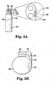
- FIGS. 4A-4B show yet another embodiment of the present invention.
- the acoustic sensor 62 shown in FIGS. 4A-4B is located in a sensor module or tab 70, which is located outside of the pulse generator 12.
- the tab 70 is structurally separate from the pulse generator 12.
- the acoustic sensor 62 is electrically connected to the circuitry 52 via a conductive member 72.
- the acoustic sensor 62 is coupled using any wireless communication technique known in the art.
- the tab 70 can be comprised of titanium and includes a compartment diaphragm 58 and a cavity 60.
- the tab 70 may be implanted near the patient's heart in a location adapted to detect key heart sounds, such as S1 and S2.
- the sensor 62 may be coupled either to the back wall of the tab 70 or directly to the diaphragm 58.
- the cavity 60 is filled with a fluid or gel that has an acoustic impedance generally matching that of thy body.
- FIG. 5 shows yet another embodiment of the present invention.
- the acoustic sensor 62 may comprise a cylindrical transducer as is known in the art, such as for example a piezoelectric cylindrical transducer.
- the sensor 62 may also comprise a generally flat MEMS transducer, as described above. This MEMS transducer may have a variety of shapes, including for example round, oval, rectangular or square.
- the acoustic sensor 62 is located on the lead 14 near the distal end 20 and is electrically connected to the circuitry 52 via a conductive member 72.
- the IMD 10 includes more than one acoustic sensor 62.
- it may include a first acoustic sensor 62 located in the housing 48 (see for example FIG. 2A ) and a second acoustic sensor 62 located on a lead (see for example FIG. 5 ).
- FIG. 6 shows at least a portion of the circuitry 52, for processing the signals received from the acoustic sensor 62, according to one embodiment of the present invention.
- the signal e.g., a voltage
- the analog signal is then converted to a digital signal by an analog-to-digital converter 76.
- This digital signal is then directed into a microprocessor or controller 78 for analysis.
- the signals may also be stored in a memory 80 coupled to the controller 78.
- the circuitry 52 may also include a sensing/stimulating circuit 82 for processing the electrical signals received from or delivered to the lead 14.
- the circuit 82 in one embodiment, generates an electrocardiogram (ECG), which is provided to the controller 78.
- ECG electrocardiogram
- Such a configuration as is shown in FIG. 6 allows the controller 78 to receive and store signals from the acoustic sensor 62 and/or from the lead 14. The controller 78 then analyzes these signals to identify heart sounds (e.g., S1, S2, S3, S4, MR and S2 splitting) and lung sounds (e.g., coughs, rales, and wheezes) and modifies therapy, as appropriate, based on the information these signals provide about the functioning of a patient's heart. In one embodiment, the controller 78 stores and averages several cycles (e.g., 10 cycles) of heart sound data, to help attenuate signal noise.
- heart sounds e.g., S1, S2, S3, S4, MR and S2 splitting
- lung sounds e.g., coughs, rales, and wheezes
- the controller 78 is programmed to subject the signal to a Fourier transform algorithm, such as a fast Fourier transform (FFT), which may provide for a more efficient technique for identifying certain chest sounds.
- FFT fast Fourier transform
- the controller 78 initiates this process of receiving signals from the acoustic sensor 62 at a predetermined time interval (e.g., hourly).
- the controller 78 continuously receives and evaluates signals from the acoustic sensor 62.
- the process is initiated upon detection of some prespecified condition, such as for example the detection by the controller 78 of a cardiac arrhythmia.
- identifying a specified chest sounds may be employed, including, for example, analyzing the signal from the acoustic sensor 62 to identify the presence of a signal exceeding a certain amplitude within a certain frequency range and within a specified portion of the cardiac cycle.
- a specified chest sound is identified by comparing the signal to an acoustic template representing a "normal" condition or to sounds previously recorded for that particular patient. These previously recorded sounds could, for example, be stored during an examination by a physician, after the physician confirms acceptable heart function.
- the ECG information is used to further assist in detecting a specified heart sound.
- the ECG information may be used to "window" a certain portion of the acoustic data, based on knowledge of a skilled artisan relating to the location in the cardiac cycle during which a specified sound is likely to occur.
- Exemplary techniques for identifying a specified heart sound and for correlating the acoustic data to a certain location in the cardiac cycle is disclosed in commonly-assigned U.S. Publication 2004/0106961 .
- the circuitry 52 further includes a logbook feature.
- the controller 78 may operate to store a predetermined time period of data in a specified area of the memory 80 periodically, or it may operate to store a specified time period of data only upon detection of an abnormal condition. This feature then allows a user to access this stored data at a later time for additional analysis.
- the system further includes an external device 84, which is operatively coupled to the circuitry 52 by, for example, a wireless RF communication link.
- the external device 84 may, for example, be an external programmer adapted for use with the implanted medical device 10.
- This external device 84 is, in turn, coupled to a remote system 86.
- the external device 84 and remote system 86 may, for example, be coupled by a telephone line, electrical or optical cable, RF interface, satellite link, local area network or wide area network.
- the remote system 86 allows a user (e.g., a physician) located at a remote location to obtain data relating to the heart sounds and to conduct or aid in the diagnosis of a patient based on such data.
- the remote system 86 includes an advanced patient management system, such as is disclosed in U.S. Publication 2004/0122484 .
Description
- The present invention relates to sensors used in combination with a cardiac function management device such as a heart pacemaker or defibrillator to monitor and control the rhythm of the heart. The present invention more particularly relates to sensors used to detect heart sounds and methods of modifying therapy based on these heart sounds.
- Cardiac function management systems are used to treat heart arrhythmias. Pacemaker systems are commonly implanted in patients to treat bradycardia (i.e., abnormally slow heart rate). A pacemaker system includes an implantable pulse generator and leads, which form the electrical connection between the implantable pulse generator and the heart. An implantable cardioverter defibrillator ("ICD") is used to treat tachycardia (i.e., abnormally rapid heart rate). An ICD also includes a pulse generator and leads that deliver electrical energy to the heart. These systems are also useful in the treatment of heart failure, which is often caused by bundle branch block that can disrupt synchrony between the right and left ventricles. For example, cardiac resynchronization therapy ("CRT") (also commonly referred to as biventricular pacing) is an emerging treatment for heart failure, which involves stimulation of both the right and the left ventricles to increase hemodynamic efficiency and cardiac output.
- The beating heart produces a series of auditory vibrations (i.e., heart sounds) that can be characterized by intensity, frequency, quality, and timing with respect to the cardiac cycle. Two of the normal heart sounds, commonly known as the S1 and S2 sounds, relate to closing of various heart valves. Specifically, the S1 sound is generated by the closing of the mitral and tricuspid valves and thus generally correlates to the onset of ventricular systole, and the S2 sound is generated by the closing of the pulmomary and aortic valves and thus generally correlates to the onset of ventricular diastole. These sounds may also indicate problems or abnormalities in the pumping process, such as for example a murmur or mitral regurgitation. There is thus a need for a cardiac rhythm management device that includes a sensor for sensing heart sounds.
-
EP 1 151 719 A2 discloses an apparatus for monitoring the condition of a heart failure patient. An implantable or other ambulatory monitor senses the patient's respiratory patterns to identify the presence of periodic breathing, medical changes of the thorax due to breathing are detected and this data is used to recognize hyperventilation and apnea or hypoventilation. Mechanical changes of the thorax are detected using an ultrasound transducer or an intrathoracic pressure transducer. The implantable or other ambulatory device is used with one or a plurality of sensors, electronic circuitry that is coupled to the sensors and processes their output, a transmitter/receiver for telemetrically conveying information between the monitor and an external unit, and a patient alert which notifies the patient if medical attention should be sought. - Further,
EP 0 798 016 A2 describes a pacemaker system which utilizes a pressure sensor positioned in the implantable pacemaker. Relative pressure signals∼ are transmitted from the patient's heart through the lumen of a pacing lead, which signals are communicated to the pressure sensor mounted either within the pacemaker connector block, or within the encapsulated pacemaker can. By this arrangement, the pacemaker-mounted sensor receives detectable pressure variations representative of heart movement, and is able to transform such relative pressure signals into parameter signals for use in controlling a pacemaker operating variable such as pacing rate. - The present invention relates to an implantable medical device (IMID) including a pulse generator having a housing and a compartment which defines an isolated cavity. A compartment diaphragm is disposed over and encloses the cavity. An acoustic sensor is adapted to sense chest sounds and generate a signal. A control circuit disposed within the pulse generator is operatively coupled to the acoustic sensor and is adapted to receive the signal.
- The cavity is hermetically sealed and bounded by back wall, and the compartment diaphragm has a resonance frequency greater than about 20 kHz. The acoustic sensor has a sensor diaphragm and is adapted to sense chest sounds having a frequency from about 10 Hz to about 20 kHz. The sensor is disposed between the compartment diaphragm and the back wall such that a space is maintained between the sensor diaphragm and the compartment diaphragm, the space being filled with a fluid or gel, which has an independence that generally matches the impedance of the human body.
- While multiple embodiments are disclosed, still other embodiments of the present invention will become apparent to those skilled in the art from the following detailed description, which shows and describes illustrative embodiments of the invention. Accordingly, the drawings and detailed description are to be regarded as illustrative in nature and not restrictive.
-
-
FIG. 1 shows a perspective view of a cardiac rhythm management device according to the present invention. -
FIGS. 2A-2C show various views of a cardiac rhythm management device having an acoustic sensor according to one embodiment of the present invention. -
FIGS. 3A-3B show various views of a cardiac rhythm management device having an acoustic sensor according to another embodiment of the present invention. -
FIGS. 4A-4B show various views of a cardiac rhythm management device having an acoustic sensor according to yet another embodiment of the present invention. -
FIG. 5 shows a perspective view of a cardiac rhythm management device having an acoustic sensor according to another embodiment of the present invention. -
FIG. 6 shows a circuit diagram, for receiving and processing a signal from an acoustic sensor, according to one embodiment of the present invention. - While the invention is amenable to various modifications and alternative forms, specific embodiments have been shown by way of example in the drawings and are described in detail below. The intention, however, is not to limit the invention to the particular embodiments described. On the contrary, the invention is intended to cover all modifications, equivalents, and alternatives falling within the scope of the invention as defined by the appended claims.
-
FIG. 1 is a perspective view of an implantable medical device (IMD) or cardiac function management (CFM)system 10. Thesystem 10 includes apulse generator 12 and acardiac lead 14. Thelead 14 operates to convey electrical signals between theheart 16 and thepulse generator 12. Aproximal end 18 of thelead 14 is coupled to thepulse generator 12 and adistal end 20 is coupled to theheart 16. Thelead 14 includes a lead body extending from the leadproximal end 18 to the leaddistal end 20. - The
heart 16 includes aright atrium 22, a right ventricle (RV) 24, and apulmonary artery 26. Atricuspid valve 28 is located between and controls the flow of blood from theright atrium 22 and theright ventricle 24. Apulmonic valve 30 is located between and controls the flow of blood from theright ventricle 24 to thepulmonary artery 26. Theheart 16 also includes aleft atrium 32, a left ventricle (LV) 34, and anaorta 36. Amitral valve 38 is located between and controls the flow of blood from theleft atrium 32 to theleft ventricle 34. Aaortic valve 40 is located between and controls the flow of blood from theleft ventricle 34 to theaorta 36. In one embodiment, theCFM system 10 includes a plurality ofleads 14. For example, it may include afirst lead 14 in communication with theleft ventricle 34 and a second lead in communication with theright ventricle 24. - The heart sound S1 is generated when the
mitral valve 38 and thetricuspid valve 28 close. The S1 sound is referred to as the "lub" part of the "lub-dub" rhythm of the heart. The heart sound S2 is generated when thepulmonic valve 30 and theaortic valve 40 close and is referred to as the "dub" sound. The S3 heart sound is known to be a ventricular diastolic filling sound often indicative of certain pathological conditions including heart failure, and the S4 heart sound is known to be a ventricular diastolic filling sound resulting from atrial contraction and is also usually indicative of pathological conditions. The phrase "heart sound," as used herein refers to any sound made by the heart during operation, including any of S1, S2, S3, S4, or any components thereof. Other notable heart sounds include that of mitral regurgitation (MR). The phrase "chest sound," as used herein includes heart sounds as well as lung sounds and any other sounds that may be present in a patient's chest cavity. Common lung sounds of interest include coughs, rales and wheezes. Other chest sounds may include, for example, snoring and talking. - In the embodiment shown in
FIG. 1 , ahelical electrode 42 penetrates the endocardium of theRV 24 and is embedded in themyocardium 44 of theheart 16. When positioned as above, theelectrode 42 can be used to sense the electrical activity of theheart 16 or to apply a stimulating pulse to theleft ventricle 34. In other embodiments, thecardiac lead 14 of the present invention can also be implanted in any other portion of theheart 16 as known in the art of cardiac function management. For example, it may be implanted in theright atrium 22, theright ventricle 24, thepulmonary artery 26, theleft ventricle 34, or in the coronary veins. In one embodiment, thesystem 10 includesmultiple electrodes 42 disposed to sense electrical activity and/or deliver therapy to both the left and right sides of theheart 16. -
FIGS. 2A and 2B show side views of thepulse generator 12 according to embodiments of the present invention. As shown inFIG. 2A , thepulse generator 12 includes aheader 46 and ahousing 48. Theheader 46 includesconnectors 50 for connecting to thelead 14. Thehousing 48 enclosescircuitry 52 and includes an outer wall or substantiallyplanar face 54. - As shown in
FIG. 2B , a coin orcompartment 56 is located on theplanar face 54. Thecompartment 56 may protrude from the planar face 54 (in which case the back wall of thecompartment 56 is the substantiallyplanar face 54 of the housing 48) or may be inset into thehousing 48. Thecompartment 56 includes acompartment diaphragm 58 and acavity 60 located behind the compartment diaphragm 58 (shown in the enlarged section ofFIG. 2A ). Anacoustic sensor 62 is located in thecavity 60 between thecompartment diaphragm 58 and back wall of thecompartment 56. In the embodiment where thecompartment 56 is inset into the housing, thecompartment diaphragm 58 is generally flush with the face of the surrounding wall of thehousing 48. In one embodiment, thecavity 60 contains a fluid or gel having an acoustic impedance that is generally an acoustic match to that of the body in which it is implanted. This fluid or gel may be any substance generally known in the art having an impedance that generally matches that of the human body, such as for example water or an ultrasound gel. - In the embodiment shown in
FIGS. 2A-2C , thecavity 60 is hermetically sealed. Thehousing 48 is comprised of titanium and may for example have a thickness of about 0.010 inch. Thecompartment diaphragm 58 is also comprised of titanium and has a thickness less than the thickness of the housing. Reducing the thickness of thecompartment diaphragm 58 allows acoustic energy to vibrate thecompartment diaphragm 58 more easily. In one embodiment, thecompartment diaphragm 58 has a thickness of between about 0.002 inch and about 0.010 inch. In one embodiment, the resonant frequency of thecompartment diaphragm 58 is much higher than the acoustic frequencies of interest in order to ensure a reasonably flat acoustic response over frequency. In one embodiment, for example, the resonant frequency of thecompartment diaphragm 58 is greater than about 20,000 Hz. - The
acoustic sensor 62 is adapted to sense broadband chest sounds, which may include for example heart and lung sounds such as S2 splitting, mitral regurgitation, coughs, rales, and wheezes. Other chest sounds, which may be detected by theacoustic sensor 62 include Gallop sounds, snoring and a patient's voice. Theacoustic sensor 62 is electrically connected to thecircuitry 52 by one ormore feedthroughs 64. Thesensor 62 may have, for example, a broadband acoustic range of from about 10 to about 20,000 Hz. In one embodiment, the range of thesensor 62 is from about 100 to about 5,000 Hz, and, in yet another embodiment, the range is from about 100 ' to about 3,000 Hz. - The
acoustic sensor 62 can be comprised of any of a variety of microphones known in the art. Exemplary microphones include piezoelectric, piezoresistive, and capacitive-type microphones. The piezoelectric microphone may be made from any piezoelectric material, including piezocomposites, piezoceramics, piezoplastics and the like. Thesensor 62 may, for example, be comprised of a piezoelectric film, such as polyvinylidine fluoride (PVDF), which takes the form of a thin plastic polymer sheet and may have a thin electrically conductive nickel copper alloy deposited on each side. Thesensor 62 acts as a strain gage that generates an electrical signal when thecompartment diaphragm 58 vibrates in response to a heart or lung sound. - In one embodiment, the
acoustic sensor 62 is a micro-electrical mechanical system (MEMS) device. One such exemplary device is the SiSonic MEMS microphone available from Knowles Acoustics, Inc. (www.knowlesacoustics.com) of Itasca, Illinois. A MEMS microphone is fabricated from a silicon chip using standard semiconductor processing techniques. Such a microphone may include a diaphragm and a backplate fabricated from a silicon wafer. In one embodiment, the thickness of thesensor 62 is from about 0.01 to about 2 mm. In another embodiment, the thickness of thesensor 62 is less than about 0.5 mm. Theacoustic sensor 62 may have a width dimension and a length dimension each between about 1 and about 2 mm. -
FIGS. 2A and 2B illustrative two exemplary locations for thesensor 62 in thecavity 60. As shown inFIG. 2A , thesensor 62 is coupled to thecompartment diaphragm 58. In this embodiment, the diaphragm of thesensor 62 may be mechanically coupled to thecompartment diaphragm 58. In one exemplary embodiment, a piezoelectric or piezoresistive material is attached to an inner surface of thecompartment diaphragm 58 using an epoxy or a medical adhesive as is known in the art. - As shown in
FIG. 2B , thesensor 62 is located on the back wall of thecompartment 56, which is defined by theplanar face 54 of thehousing 48. In this embodiment; thesensor 62 may include an opening to allow the portion of thesensor 62 located between the diaphragm and theplanar face 54 to communicate with the remainder of thecavity 60, which minimizes acoustic dampening in thesensor 62. In the embodiment ofFIG. 2B , the diaphragm of theacoustic sensor 62 is separated from thecompartment diaphragm 58 by a small distance. As noted above, this separation space in thecavity 60 may be filled with a fluid having an appropriate acoustic impedance. - In one embodiment, the
acoustic sensor 62 is an accelerometer, including, for example, a piezoelectric crystal accelerometer sensor of the type used by pacemakers to sense the level of activity of the patient. Use of such an accelerometer for detecting heart sounds is described in more detail, for example, inU.S. Publication 2005/0137490 andU.S. Publication 2005/0102001 . In another exemplary embodiment, theIMD 10 includes both an accelerometer and a piezoelectric sensor. In this embodiment, the accelerometer is typically located inside the hermetic housing and is generally most effective at sensing lower frequencies, whereas the sensor is in a cavity located behind a diaphragm and is optimized for detecting frequencies above that detected by the accelerometer. - The
compartment diaphragm 58 and thecompartment 56 can be any shape, including circular, oval, rectangular, or square. In the embodiment shown inFIG. 2C , thecompartment diaphragm 58 and thecompartment 56 both have a circular shape. Thecompartment 46 may include a chamfer 66 to avoid irritation of the body tissue adjacent to thecompartment 56. In one embodiment, thecompartment 56 extends outwardly from theplanar face 54, while in other embodiments, thecompartment 56 is disposed within or behind theplanar face 54. -
FIGS. 3A-3B show another embodiment of the present invention. As shown, theacoustic sensor 62 is located in acavity 60 behind an outer surface 68 of theheader 46. Theheader 46 can be comprised of Tecothane or any other suitable material as is known in the art. Sealedhermetic feedthroughs 64 electrically connect theacoustic sensor 62 to thecircuitry 52. Theacoustic sensor 62 shown inFIGS. 3A-3B is a substantially flat piezoelectric, piezoresistive, or capacitive device (e.g., a MEMS microphone), but in an alternative embodiment, theacoustic sensor 62 could comprise a piezoelectric cylindrical transducer, as is known in the art. In this embodiment, theacoustic sensor 62 may be disposed within acavity 60 behind the outer surface 68, as described with respect toFIGS. 2A-2B above. Alternatively, the diaphragm of thesensor 62 may be positioned such that it is not covered over by the material that forms the header body (e.g., Tecothane). In both of these embodiment, thesensor 62 is directly exposed to bodily fluids, as the header material is not hermetically sealed and thus is penetrable by bodily fluids. - In one embodiment, the
acoustic sensor 62 ofFIGS. 3A-3B is contained in a hermetically sealed, titanium tab or housing (e.g., such as is described below with reference toFIGS. 4A and 4B ). In this exemplary embodiment, the tab or housing includes a relatively thin diaphragm to allow sound to penetrate the tab and reach theacoustic sensor 62. -
FIGS. 4A-4B show yet another embodiment of the present invention. Theacoustic sensor 62 shown inFIGS. 4A-4B is located in a sensor module ortab 70, which is located outside of thepulse generator 12. In one embodiment, as shown inFIG. 4A , thetab 70 is structurally separate from thepulse generator 12. As shown inFIG. 4A , theacoustic sensor 62 is electrically connected to thecircuitry 52 via aconductive member 72. In another embodiment, theacoustic sensor 62 is coupled using any wireless communication technique known in the art. Thetab 70 can be comprised of titanium and includes acompartment diaphragm 58 and acavity 60. Thetab 70 may be implanted near the patient's heart in a location adapted to detect key heart sounds, such as S1 and S2. As described above with respect toFIGS. 2A and 2B , thesensor 62 may be coupled either to the back wall of thetab 70 or directly to thediaphragm 58. Also as described above, in one embodiment thecavity 60 is filled with a fluid or gel that has an acoustic impedance generally matching that of thy body. -
FIG. 5 shows yet another embodiment of the present invention. In this embodiment, theacoustic sensor 62 may comprise a cylindrical transducer as is known in the art, such as for example a piezoelectric cylindrical transducer. In this embodiment, thesensor 62 may also comprise a generally flat MEMS transducer, as described above. This MEMS transducer may have a variety of shapes, including for example round, oval, rectangular or square. Theacoustic sensor 62 is located on thelead 14 near thedistal end 20 and is electrically connected to thecircuitry 52 via aconductive member 72. In yet another embodiment, theIMD 10,includes more than oneacoustic sensor 62. For example, it may include a firstacoustic sensor 62 located in the housing 48 (see for exampleFIG. 2A ) and a secondacoustic sensor 62 located on a lead (see for exampleFIG. 5 ). -
FIG. 6 shows at least a portion of thecircuitry 52, for processing the signals received from theacoustic sensor 62, according to one embodiment of the present invention. As shown, the signal (e.g., a voltage) from theacoustic sensor 62 is processed by ananalog pre-processing circuit 74, which may include, for example, a filter and/or an amplifier. The analog signal is then converted to a digital signal by an analog-to-digital converter 76. This digital signal is then directed into a microprocessor orcontroller 78 for analysis. The signals may also be stored in amemory 80 coupled to thecontroller 78. As further shown inFIG. 6 , thecircuitry 52 may also include a sensing/stimulatingcircuit 82 for processing the electrical signals received from or delivered to thelead 14. Thecircuit 82, in one embodiment, generates an electrocardiogram (ECG), which is provided to thecontroller 78. - Such a configuration as is shown in
FIG. 6 allows thecontroller 78 to receive and store signals from theacoustic sensor 62 and/or from thelead 14. Thecontroller 78 then analyzes these signals to identify heart sounds (e.g., S1, S2, S3, S4, MR and S2 splitting) and lung sounds (e.g., coughs, rales, and wheezes) and modifies therapy, as appropriate, based on the information these signals provide about the functioning of a patient's heart. In one embodiment, thecontroller 78 stores and averages several cycles (e.g., 10 cycles) of heart sound data, to help attenuate signal noise. In another embodiment, thecontroller 78 is programmed to subject the signal to a Fourier transform algorithm, such as a fast Fourier transform (FFT), which may provide for a more efficient technique for identifying certain chest sounds. In one embodiment, thecontroller 78 initiates this process of receiving signals from theacoustic sensor 62 at a predetermined time interval (e.g., hourly). In other embodiments, thecontroller 78 continuously receives and evaluates signals from theacoustic sensor 62. In another embodiment, the process is initiated upon detection of some prespecified condition, such as for example the detection by thecontroller 78 of a cardiac arrhythmia. - Several techniques for identifying a specified chest sounds may be employed, including, for example, analyzing the signal from the
acoustic sensor 62 to identify the presence of a signal exceeding a certain amplitude within a certain frequency range and within a specified portion of the cardiac cycle. In one embodiment, a specified chest sound is identified by comparing the signal to an acoustic template representing a "normal" condition or to sounds previously recorded for that particular patient. These previously recorded sounds could, for example, be stored during an examination by a physician, after the physician confirms acceptable heart function. In one embodiment, the ECG information is used to further assist in detecting a specified heart sound. The ECG information, for example, may be used to "window" a certain portion of the acoustic data, based on knowledge of a skilled artisan relating to the location in the cardiac cycle during which a specified sound is likely to occur. Exemplary techniques for identifying a specified heart sound and for correlating the acoustic data to a certain location in the cardiac cycle is disclosed in commonly-assignedU.S. Publication 2004/0106961 . - In one embodiment, the
circuitry 52 further includes a logbook feature. In this embodiment, for example, thecontroller 78 may operate to store a predetermined time period of data in a specified area of thememory 80 periodically, or it may operate to store a specified time period of data only upon detection of an abnormal condition. This feature then allows a user to access this stored data at a later time for additional analysis. - In one embodiment, the system further includes an
external device 84, which is operatively coupled to thecircuitry 52 by, for example, a wireless RF communication link. Theexternal device 84 may, for example, be an external programmer adapted for use with the implantedmedical device 10. Thisexternal device 84 is, in turn, coupled to aremote system 86. Theexternal device 84 andremote system 86 may, for example, be coupled by a telephone line, electrical or optical cable, RF interface, satellite link, local area network or wide area network. Theremote system 86 allows a user (e.g., a physician) located at a remote location to obtain data relating to the heart sounds and to conduct or aid in the diagnosis of a patient based on such data. In one embodiment, theremote system 86 includes an advanced patient management system, such as is disclosed inU.S. Publication 2004/0122484 . - Various modifications and additions can be made to the exemplary embodiments discussed without departing from the scope of the present invention. Accordingly, the scope of the present invention is intended to embrace all such alternatives, modifications, and variations as fall within the scope of the claims.
Claims (13)
- An implantable medical device (IMD) comprising:a pulse generator (12) having a housing (48) and a compartment (56), the compartment (56) defining an isolated cavity (60);a compartment diaphragm (58) disposed over and enclosing the cavity (60);an acoustic sensor (62) adapted to sense chest sounds and generate a signal; anda control circuit (52) disposed within the housing (48) of the pulse generator (12), the circuit (52) operatively coupled to the acoustic sensor (52) and adapted to receive the signal,characterized in that the compartment (56) is disposed outside of the housing (48);the cavity (60) is hermetically sealed and bounded by an outer wall (54) of the housing (48);the compartment diaphragm (58) having a resonance frequency greater than about 20 kHz, the acoustic sensor (62) has a sensor diaphragm and is adapted to sense chest sounds having a frequency from about 10 Hz to about 20 kHz, the sensor (62) being disposed between the compartment diaphragm (58) and the outer wall (54) of the housing (48) such that a space is maintained between the sensor diaphragm and the compartment diaphragm (58), the space being filled with a fluid or gel, the fluid or gel having an impedance that generally matches the impedance of the human body.
- The IMD of claim 1 wherein an acoustic range of the acoustic sensor (62) is from about 100 to about 5,000 Hz.
- The IMD of claim 1 or claim 2, further comprising an accelerometer operatively coupled to the control circuit (52).
- The IMD of any of the preceding claims wherein the acoustic sensor (62) includes an amplifier for amplifying the signal detected by the acoustic sensor (62).
- The IMD of any of the preceding claims wherein the acoustic sensor (62) is a piezoresistive sensor or a capacitive sensor.
- The IMD of any of the preceding claims wherein the acoustic sensor (62) is a MEMS microphone, and further wherein the MEMS microphone is attached to the outer wall (54).
- The IMD of any of the preceding claims wherein the sensor diaphragm of the acoustic sensor (62) is made from a piezoelectric material.
- The IMD of claim 7 wherein the piezoelectric material comprises a piezoceramic material.
- The IMD of any of the preceding claims wherein the sensor diaphragm is attached to the compartment diaphragm (58) using an epoxy or medical adhesive.
- The IMD of any of the preceding claims wherein the pulse generator (12) includes a housing (48) and a header (46).
- The IMD of any of the preceding claims wherein the compartment (56) extends outwardly from the housing outer wall (54).
- The IMD of any of the preceding claims wherein the electrical connection between the acoustic sensor (62) and the control circuit (52) includes a hermetically sealed feedthrough (64).
- The IMD of any of the preceding claims wherein the compartment (56) is disposed in the header (46).
Applications Claiming Priority (2)
| Application Number | Priority Date | Filing Date | Title |
|---|---|---|---|
| US11/212,176 US7615012B2 (en) | 2005-08-26 | 2005-08-26 | Broadband acoustic sensor for an implantable medical device |
| PCT/US2006/033273 WO2007025163A1 (en) | 2005-08-26 | 2006-08-25 | Broadband acoustic sensor for an implantable medical device |
Publications (2)
| Publication Number | Publication Date |
|---|---|
| EP1921996A1 EP1921996A1 (en) | 2008-05-21 |
| EP1921996B1 true EP1921996B1 (en) | 2014-04-30 |
Family
ID=37591901
Family Applications (1)
| Application Number | Title | Priority Date | Filing Date |
|---|---|---|---|
| EP06813763.7A Not-in-force EP1921996B1 (en) | 2005-08-26 | 2006-08-25 | Broadband acoustic sensor for an implantable medical device |
Country Status (4)
| Country | Link |
|---|---|
| US (1) | US7615012B2 (en) |
| EP (1) | EP1921996B1 (en) |
| JP (1) | JP4889127B2 (en) |
| WO (1) | WO2007025163A1 (en) |
Families Citing this family (38)
| Publication number | Priority date | Publication date | Assignee | Title |
|---|---|---|---|---|
| US20030036746A1 (en) | 2001-08-16 | 2003-02-20 | Avi Penner | Devices for intrabody delivery of molecules and systems and methods utilizing same |
| US8271093B2 (en) | 2004-09-17 | 2012-09-18 | Cardiac Pacemakers, Inc. | Systems and methods for deriving relative physiologic measurements using a backend computing system |
| DE602005024179D1 (en) * | 2004-11-24 | 2010-11-25 | Remon Medical Technologies Ltd | IMPLANTABLE MEDICINE PRODUCT WITH INTEGRATED ACOUSTIC CONVERTER |
| US7813808B1 (en) | 2004-11-24 | 2010-10-12 | Remon Medical Technologies Ltd | Implanted sensor system with optimized operational and sensing parameters |
| US7570998B2 (en) * | 2005-08-26 | 2009-08-04 | Cardiac Pacemakers, Inc. | Acoustic communication transducer in implantable medical device header |
| US7742815B2 (en) * | 2005-09-09 | 2010-06-22 | Cardiac Pacemakers, Inc. | Using implanted sensors for feedback control of implanted medical devices |
| US20070208390A1 (en) * | 2006-03-01 | 2007-09-06 | Von Arx Jeffrey A | Implantable wireless sound sensor |
| US7744542B2 (en) * | 2006-04-20 | 2010-06-29 | Cardiac Pacemakers, Inc. | Implanted air passage sensors |
| US20080186691A1 (en) * | 2006-04-28 | 2008-08-07 | Mertz John C | Implantable medical device housing reinforcement |
| US7955268B2 (en) | 2006-07-21 | 2011-06-07 | Cardiac Pacemakers, Inc. | Multiple sensor deployment |
| EP2043740A2 (en) | 2006-07-21 | 2009-04-08 | Cardiac Pacemakers, Inc. | Ultrasonic transducer for a metallic cavity implanted medical device |
| US7912548B2 (en) * | 2006-07-21 | 2011-03-22 | Cardiac Pacemakers, Inc. | Resonant structures for implantable devices |
| US20080077440A1 (en) * | 2006-09-26 | 2008-03-27 | Remon Medical Technologies, Ltd | Drug dispenser responsive to physiological parameters |
| US8709631B1 (en) * | 2006-12-22 | 2014-04-29 | Pacesetter, Inc. | Bioelectric battery for implantable device applications |
| US8290577B2 (en) * | 2007-03-23 | 2012-10-16 | Brooks Donald J | Methods and apparatus for enhanced fiducial point determination and non-invasive hemodynamic parameter determination |
| US8825161B1 (en) | 2007-05-17 | 2014-09-02 | Cardiac Pacemakers, Inc. | Acoustic transducer for an implantable medical device |
| US7901360B1 (en) * | 2007-05-17 | 2011-03-08 | Pacesetter, Inc. | Implantable sensor for measuring physiologic information |
| EP2162185B1 (en) * | 2007-06-14 | 2015-07-01 | Cardiac Pacemakers, Inc. | Multi-element acoustic recharging system |
| US7682316B2 (en) * | 2007-07-23 | 2010-03-23 | Medtronic, Inc. | Implantable heart sound sensor with noise cancellation |
| EP2242538B1 (en) * | 2008-02-11 | 2016-04-06 | Cardiac Pacemakers, Inc. | Methods of monitoring hemodynamic status for ryhthm discrimination within the heart |
| WO2009102640A1 (en) * | 2008-02-12 | 2009-08-20 | Cardiac Pacemakers, Inc. | Systems and methods for controlling wireless signal transfers between ultrasound-enabled medical devices |
| US8591423B2 (en) * | 2008-10-10 | 2013-11-26 | Cardiac Pacemakers, Inc. | Systems and methods for determining cardiac output using pulmonary artery pressure measurements |
| WO2010059291A1 (en) | 2008-11-19 | 2010-05-27 | Cardiac Pacemakers, Inc. | Assessment of pulmonary vascular resistance via pulmonary artery pressure |
| US8184503B2 (en) * | 2009-05-18 | 2012-05-22 | Magnetrol International, Incorporated | Process measurement instrument with target rejection |
| US20100324378A1 (en) * | 2009-06-17 | 2010-12-23 | Tran Binh C | Physiologic signal monitoring using ultrasound signals from implanted devices |
| US8491488B1 (en) | 2010-10-01 | 2013-07-23 | Blaufuss Medical Multimedia Laboratories, LLC | Method and system for identifying cardiopulmonary findings by using a heart and lung sounds builder |
| US8617082B2 (en) | 2011-05-19 | 2013-12-31 | Medtronic, Inc. | Heart sounds-based pacing optimization |
| US8876727B2 (en) | 2011-05-19 | 2014-11-04 | Medtronic, Inc. | Phrenic nerve stimulation detection using heart sounds |
| US8777874B2 (en) * | 2011-05-24 | 2014-07-15 | Medtronic, Inc. | Acoustic based cough detection |
| WO2013003908A1 (en) * | 2011-07-06 | 2013-01-10 | Brc Ip Pty Ltd | Pulse sensor measurement system and method |
| US8886311B2 (en) | 2012-01-27 | 2014-11-11 | Medtronic, Inc. | Techniques for mitigating motion artifacts from implantable physiological sensors |
| US9095718B2 (en) | 2012-04-04 | 2015-08-04 | Medtronic, Inc. | Heart-sounds based adaptive cardiac resynchronization therapy timing parameter optimization system |
| JP6140881B2 (en) * | 2013-03-12 | 2017-06-07 | カーディアック ペースメイカーズ, インコーポレイテッド | Heart sound template comparison to identify true pacing modes |
| EP3100762B1 (en) * | 2015-06-02 | 2020-04-01 | BIOTRONIK SE & Co. KG | Diagnostic medical product having an adhesion-enhancing surface structure |
| US9795796B2 (en) * | 2015-08-25 | 2017-10-24 | Pacesetter, Inc. | Implantable electronic device employing fused thermoplastic-conductor subassembly and method of manufacturing the subassembly and the device |
| WO2017100691A1 (en) * | 2015-12-09 | 2017-06-15 | The Alfred E. Mann Foundation For Scientific Research | Implantable pressure sensors and medical devices |
| WO2018017226A1 (en) * | 2016-07-20 | 2018-01-25 | Cardiac Pacemakers, Inc. | System for utilizing an atrial contraction timing fiducial in a leadless cardiac pacemaker system |
| WO2019036600A1 (en) * | 2017-08-18 | 2019-02-21 | Cardiac Pacemakers, Inc. | Implantable medical device with pressure sensor |
Family Cites Families (136)
| Publication number | Priority date | Publication date | Assignee | Title |
|---|---|---|---|---|
| US2967957A (en) * | 1957-09-17 | 1961-01-10 | Massa Frank | Electroacoustic transducer |
| DE1967130C2 (en) * | 1968-01-25 | 1982-04-01 | Pioneer Electronic Corp., Tokyo | Mechanical-electrical or electrical-mechanical converter |
| US3568661A (en) * | 1968-10-02 | 1971-03-09 | Us Health Education & Welfare | Frequency modulated ultrasound technique for measurement of fluid velocity |
| JPS4926890B1 (en) * | 1970-12-04 | 1974-07-12 | ||
| US3676720A (en) * | 1971-01-26 | 1972-07-11 | Univ Ohio | Method and apparatus for controlling frequency of piezoelectric transducers |
| US3757770A (en) * | 1971-02-22 | 1973-09-11 | Bio Tel Western | Physiological pressure sensing and telemetry means employing a diode connected transistor transducer |
| JPS5221364B2 (en) * | 1971-11-04 | 1977-06-10 | ||
| JPS5123439B2 (en) * | 1971-11-05 | 1976-07-16 | ||
| JPS5410214B2 (en) * | 1973-10-15 | 1979-05-02 | ||
| JPS5215972B2 (en) * | 1974-02-28 | 1977-05-06 | ||
| JPS5220297Y2 (en) * | 1974-05-10 | 1977-05-10 | ||
| US4170742A (en) | 1974-07-15 | 1979-10-09 | Pioneer Electronic Corporation | Piezoelectric transducer with multiple electrode areas |
| GB1520118A (en) | 1975-08-11 | 1978-08-02 | Rank Organisation Ltd | Transducers |
| US4051455A (en) * | 1975-11-20 | 1977-09-27 | Westinghouse Electric Corporation | Double flexure disc electro-acoustic transducer |
| US4056742A (en) | 1976-04-30 | 1977-11-01 | Tibbetts Industries, Inc. | Transducer having piezoelectric film arranged with alternating curvatures |
| US4127110A (en) | 1976-05-24 | 1978-11-28 | Huntington Institute Of Applied Medical Research | Implantable pressure transducer |
| US4653508A (en) * | 1976-06-21 | 1987-03-31 | Cosman Eric R | Pressure-balanced telemetric pressure sensing system and method therefore |
| US4660568A (en) * | 1976-06-21 | 1987-04-28 | Cosman Eric R | Telemetric differential pressure sensing system and method therefore |
| US4593703A (en) * | 1976-06-21 | 1986-06-10 | Cosman Eric R | Telemetric differential pressure sensor with the improvement of a conductive shorted loop tuning element and a resonant circuit |
| US4096756A (en) * | 1977-07-05 | 1978-06-27 | Rca Corporation | Variable acoustic wave energy transfer-characteristic control device |
| US4181864A (en) * | 1978-06-22 | 1980-01-01 | Rca Corporation | Matching network for switchable segmented ultrasonic transducers |
| US4227407A (en) | 1978-11-30 | 1980-10-14 | Cornell Research Foundation, Inc. | Volume flow measurement system |
| US4481950A (en) | 1979-04-27 | 1984-11-13 | Medtronic, Inc. | Acoustic signalling apparatus for implantable devices |
| US4281484A (en) * | 1980-02-11 | 1981-08-04 | The Stoneleigh Trust | System for precisely and economically adjusting the resonance frequence of electroacoustic transducers |
| DE3009068A1 (en) | 1980-03-10 | 1981-09-24 | Reinhard Dipl.-Ing. Lerch | PIEZOPOLYMER CONVERTER WITH FIXED MEMBRANE SUPPORT |
| US4433400A (en) * | 1980-11-24 | 1984-02-21 | The United States Of America As Represented By The Department Of Health And Human Services | Acoustically transparent hydrophone probe |
| US4517665A (en) * | 1980-11-24 | 1985-05-14 | The United States Of America As Represented By The Department Of Health And Human Services | Acoustically transparent hydrophone probe |
| CA1157142A (en) * | 1981-01-09 | 1983-11-15 | Robert G. Dunn | Diaphragm design for a bender type acoustic sensor |
| JPS58137317A (en) * | 1982-02-09 | 1983-08-15 | Nec Corp | Thin-film piezoelectric compound oscillator |
| US5438553A (en) * | 1983-08-22 | 1995-08-01 | Raytheon Company | Transducer |
| US4519401A (en) * | 1983-09-20 | 1985-05-28 | Case Western Reserve University | Pressure telemetry implant |
| GB8325861D0 (en) * | 1983-09-28 | 1983-11-02 | Syrinx Presicion Instr Ltd | Force transducer |
| US4603701A (en) * | 1983-12-16 | 1986-08-05 | Hewlett-Packard Company | Stand-off device with special fluid |
| US5178153A (en) * | 1984-03-08 | 1993-01-12 | Einzig Robert E | Fluid flow sensing apparatus for in vivo and industrial applications employing novel differential optical fiber pressure sensors |
| JPS60189307A (en) * | 1984-03-09 | 1985-09-26 | Toshiba Corp | Piezoelectric thin film resonator and its manufacture |
| DE8408180U1 (en) * | 1984-03-16 | 1986-07-17 | Siemens AG, 1000 Berlin und 8000 München | Piezoelectric air-ultrasonic transducer with broadband characteristics |
| GB8422876D0 (en) | 1984-09-11 | 1984-10-17 | Secr Defence | Silicon implant devices |
| US4541431A (en) | 1984-09-20 | 1985-09-17 | Telectronics Pty. Ltd. | Use of telemetry coil to replace magnetically activated reed switch in implantable devices |
| US4653036A (en) * | 1984-10-23 | 1987-03-24 | The United States Of America As Represented By The Department Of Health And Human Services | Transducer hydrophone with filled reservoir |
| US4580074A (en) * | 1984-11-26 | 1986-04-01 | General Motors Corporation | Piezoelectric transducer with coded output signal |
| US4676255A (en) * | 1985-07-03 | 1987-06-30 | Cosman Eric R | Telemetric in-vivo calibration method and apparatus using a negative pressure applicator |
| US4781715A (en) | 1986-04-30 | 1988-11-01 | Temple University Of The Commonwealth System Of Higher Education | Cardiac prosthesis having integral blood pressure sensor |
| US4672976A (en) * | 1986-06-10 | 1987-06-16 | Cherne Industries, Inc. | Heart sound sensor |
| US4835435A (en) * | 1988-01-19 | 1989-05-30 | Hewlett-Packard Company | Simple, sensitive, frequency-tuned drop detector |
| US4911172A (en) * | 1988-03-28 | 1990-03-27 | Telectronics Pacing Systems, Inc. | Probe tip ultrasonic transducers and method of manufacture |
| US4846191A (en) * | 1988-05-27 | 1989-07-11 | Data Sciences, Inc. | Device for chronic measurement of internal body pressure |
| DE3824171A1 (en) * | 1988-07-16 | 1990-01-18 | Teroson Gmbh | MASS SPRING SYSTEMS FOR SOUNDPROOF PURPOSES |
| US5024224A (en) * | 1988-09-01 | 1991-06-18 | Storz Instrument Company | Method of readout of implanted hearing aid device and apparatus therefor |
| DE3831809A1 (en) | 1988-09-19 | 1990-03-22 | Funke Hermann | DEVICE DETERMINED AT LEAST PARTLY IN THE LIVING BODY |
| US5012815A (en) * | 1989-02-02 | 1991-05-07 | Yale University | Dynamic spectral phonocardiograph |
| US4958100A (en) | 1989-02-22 | 1990-09-18 | Massachusetts Institute Of Technology | Actuated truss system |
| US5160870A (en) | 1990-06-25 | 1992-11-03 | Carson Paul L | Ultrasonic image sensing array and method |
| AT397898B (en) * | 1991-09-25 | 1994-07-25 | Akg Akustische Kino Geraete | MEMBRANE FOR ELECTRODYNAMIC CONVERTERS |
| US5300875A (en) * | 1992-06-08 | 1994-04-05 | Micron Technology, Inc. | Passive (non-contact) recharging of secondary battery cell(s) powering RFID transponder tags |
| US5306294A (en) * | 1992-08-05 | 1994-04-26 | Ultrasonic Sensing And Monitoring Systems, Inc. | Stent construction of rolled configuration |
| US5367500A (en) | 1992-09-30 | 1994-11-22 | The United States Of America As Represented By The Secretary Of The Navy | Transducer structure |
| US5628782A (en) * | 1992-12-11 | 1997-05-13 | W. L. Gore & Associates, Inc. | Method of making a prosthetic vascular graft |
| US5423334A (en) * | 1993-02-01 | 1995-06-13 | C. R. Bard, Inc. | Implantable medical device characterization system |
| US5410587A (en) * | 1993-03-01 | 1995-04-25 | Matsushita Communication Industrial Corp. Of America | Ultrasonic radiotelephone for an automobile |
| US5381067A (en) * | 1993-03-10 | 1995-01-10 | Hewlett-Packard Company | Electrical impedance normalization for an ultrasonic transducer array |
| US5314457A (en) * | 1993-04-08 | 1994-05-24 | Jeutter Dean C | Regenerative electrical |
| US5339290A (en) * | 1993-04-16 | 1994-08-16 | Hewlett-Packard Company | Membrane hydrophone having inner and outer membranes |
| US5873835A (en) * | 1993-04-29 | 1999-02-23 | Scimed Life Systems, Inc. | Intravascular pressure and flow sensor |
| US5381386A (en) * | 1993-05-19 | 1995-01-10 | Hewlett-Packard Company | Membrane hydrophone |
| US5289821A (en) * | 1993-06-30 | 1994-03-01 | Swartz William M | Method of ultrasonic Doppler monitoring of blood flow in a blood vessel |
| US5483501A (en) * | 1993-09-14 | 1996-01-09 | The Whitaker Corporation | Short distance ultrasonic distance meter |
| US5495137A (en) * | 1993-09-14 | 1996-02-27 | The Whitaker Corporation | Proximity sensor utilizing polymer piezoelectric film with protective metal layer |
| US5476488A (en) | 1993-12-15 | 1995-12-19 | Pacesetter, Inc. | Telemetry system power control for implantable medical devices |
| US5488954A (en) * | 1994-09-09 | 1996-02-06 | Georgia Tech Research Corp. | Ultrasonic transducer and method for using same |
| EP0706835B1 (en) * | 1994-10-10 | 1999-01-20 | Endress + Hauser GmbH + Co. | Method of operating an ultrasonic piezoelectric transducer and circuit arrangement for performing the method |
| US5562714A (en) | 1995-02-03 | 1996-10-08 | Medtronic, Inc. | Magnetic field strength regulator for implant |
| US5832924A (en) | 1995-02-16 | 1998-11-10 | Medwave, Inc. | Method of positioning a sensor for determining blood pressure of an artery |
| US5554177A (en) | 1995-03-27 | 1996-09-10 | Medtronic, Inc. | Method and apparatus to optimize pacing based on intensity of acoustic signal |
| US5956292A (en) | 1995-04-13 | 1999-09-21 | The Charles Stark Draper Laboratory, Inc. | Monolithic micromachined piezoelectric acoustic transducer and transducer array and method of making same |
| US5571152A (en) | 1995-05-26 | 1996-11-05 | Light Sciences Limited Partnership | Microminiature illuminator for administering photodynamic therapy |
| US5704352A (en) * | 1995-11-22 | 1998-01-06 | Tremblay; Gerald F. | Implantable passive bio-sensor |
| US5679026A (en) | 1995-12-21 | 1997-10-21 | Ventritex, Inc. | Header adapter for an implantable cardiac stimulation device |
| AU710983B2 (en) * | 1996-02-15 | 1999-10-07 | Armand P. Neukermans | Improved biocompatible transducers |
| US5833603A (en) | 1996-03-13 | 1998-11-10 | Lipomatrix, Inc. | Implantable biosensing transponder |
| US5825117A (en) | 1996-03-26 | 1998-10-20 | Hewlett-Packard Company | Second harmonic imaging transducers |
| US6223081B1 (en) * | 1996-03-28 | 2001-04-24 | Medtronic, Inc. | Implantable stimulus system having stimulus generator with pressure sensor and common lead for transmitting stimulus pulses to a body location and pressure signals from the body location to the stimulus generator |
| WO1997035636A1 (en) * | 1996-03-28 | 1997-10-02 | Medtronic, Inc. | Detection of pressure waves transmitted through catheter/lead body |
| US5733313A (en) * | 1996-08-01 | 1998-03-31 | Exonix Corporation | RF coupled, implantable medical device with rechargeable back-up power source |
| US5879283A (en) * | 1996-08-07 | 1999-03-09 | St. Croix Medical, Inc. | Implantable hearing system having multiple transducers |
| US5749909A (en) * | 1996-11-07 | 1998-05-12 | Sulzer Intermedics Inc. | Transcutaneous energy coupling using piezoelectric device |
| US5741316A (en) * | 1996-12-02 | 1998-04-21 | Light Sciences Limited Partnership | Electromagnetic coil configurations for power transmission through tissue |
| US5735887A (en) * | 1996-12-10 | 1998-04-07 | Exonix Corporation | Closed-loop, RF-coupled implanted medical device |
| US5792195A (en) * | 1996-12-16 | 1998-08-11 | Cardiac Pacemakers, Inc. | Acceleration sensed safe upper rate envelope for calculating the hemodynamic upper rate limit for a rate adaptive cardiac rhythm management device |
| ES2208963T3 (en) * | 1997-01-03 | 2004-06-16 | Biosense, Inc. | PRESSURE SENSITIVE VASCULAR ENDOPROTESIS. |
| US5957950A (en) | 1997-01-21 | 1999-09-28 | Northwestern University Medical School | Vascular acoustic emission analysis in a balloon angioplasty system |
| EP1666087A3 (en) * | 1997-02-26 | 2009-04-29 | The Alfred E Mann Foundation for Scientific Research | Battery-powered patient implantable device |
| US5967986A (en) | 1997-11-25 | 1999-10-19 | Vascusense, Inc. | Endoluminal implant with fluid flow sensing capability |
| US5807258A (en) | 1997-10-14 | 1998-09-15 | Cimochowski; George E. | Ultrasonic sensors for monitoring the condition of a vascular graft |
| US5843135A (en) | 1997-10-20 | 1998-12-01 | Medtronic, Inc. | Pacing system with lead having a single conductor for connecting to pressure sensor and electrode |
| US6475170B1 (en) | 1997-12-30 | 2002-11-05 | Remon Medical Technologies Ltd | Acoustic biosensor for monitoring physiological conditions in a body implantation site |
| US6140740A (en) | 1997-12-30 | 2000-10-31 | Remon Medical Technologies, Ltd. | Piezoelectric transducer |
| US5935081A (en) * | 1998-01-20 | 1999-08-10 | Cardiac Pacemakers, Inc. | Long term monitoring of acceleration signals for optimization of pacing therapy |
| US6082367A (en) * | 1998-04-29 | 2000-07-04 | Medtronic, Inc. | Audible sound communication from an implantable medical device |
| US6144880A (en) * | 1998-05-08 | 2000-11-07 | Cardiac Pacemakers, Inc. | Cardiac pacing using adjustable atrio-ventricular delays |
| US6044298A (en) * | 1998-10-13 | 2000-03-28 | Cardiac Pacemakers, Inc. | Optimization of pacing parameters based on measurement of integrated acoustic noise |
| US6554761B1 (en) * | 1999-10-29 | 2003-04-29 | Soundport Corporation | Flextensional microphones for implantable hearing devices |
| US6409675B1 (en) * | 1999-11-10 | 2002-06-25 | Pacesetter, Inc. | Extravascular hemodynamic monitor |
| US6600949B1 (en) * | 1999-11-10 | 2003-07-29 | Pacesetter, Inc. | Method for monitoring heart failure via respiratory patterns |
| US6477406B1 (en) * | 1999-11-10 | 2002-11-05 | Pacesetter, Inc. | Extravascular hemodynamic acoustic sensor |
| US6527729B1 (en) * | 1999-11-10 | 2003-03-04 | Pacesetter, Inc. | Method for monitoring patient using acoustic sensor |
| US6970742B2 (en) * | 2000-01-11 | 2005-11-29 | Savacor, Inc. | Method for detecting, diagnosing, and treating cardiovascular disease |
| DE10015421C2 (en) * | 2000-03-28 | 2002-07-04 | Implex Ag Hearing Technology I | Partially or fully implantable hearing system |
| DE10018361C2 (en) * | 2000-04-13 | 2002-10-10 | Cochlear Ltd | At least partially implantable cochlear implant system for the rehabilitation of a hearing disorder |
| DE10018334C1 (en) * | 2000-04-13 | 2002-02-28 | Implex Hear Tech Ag | At least partially implantable system for the rehabilitation of a hearing impairment |
| US7220232B2 (en) * | 2000-08-24 | 2007-05-22 | Timi 3 Systems, Inc. | Method for delivering ultrasonic energy |
| US7335169B2 (en) * | 2000-08-24 | 2008-02-26 | Timi 3 Systems, Inc. | Systems and methods for delivering ultrasound energy at an output power level that remains essentially constant despite variations in transducer impedance |
| US6741714B2 (en) * | 2000-10-04 | 2004-05-25 | Widex A/S | Hearing aid with adaptive matching of input transducers |
| US7024248B2 (en) * | 2000-10-16 | 2006-04-04 | Remon Medical Technologies Ltd | Systems and methods for communicating with implantable devices |
| US7283874B2 (en) * | 2000-10-16 | 2007-10-16 | Remon Medical Technologies Ltd. | Acoustically powered implantable stimulating device |
| US6792308B2 (en) * | 2000-11-17 | 2004-09-14 | Medtronic, Inc. | Myocardial performance assessment |
| US20020087151A1 (en) * | 2000-12-29 | 2002-07-04 | Afx, Inc. | Tissue ablation apparatus with a sliding ablation instrument and method |
| US6622044B2 (en) * | 2001-01-04 | 2003-09-16 | Cardiac Pacemakers Inc. | System and method for removing narrowband noise |
| US7052466B2 (en) * | 2001-04-11 | 2006-05-30 | Cardiac Pacemakers, Inc. | Apparatus and method for outputting heart sounds |
| US7611471B2 (en) * | 2001-05-28 | 2009-11-03 | HD Medical Inc. | Heart diagnosis system |
| US6763722B2 (en) * | 2001-07-13 | 2004-07-20 | Transurgical, Inc. | Ultrasonic transducers |
| JP2003218805A (en) * | 2002-01-25 | 2003-07-31 | Tama Tlo Kk | Power and signal transmission device using ultrasonic waves |
| WO2003068047A2 (en) * | 2002-02-11 | 2003-08-21 | Gold - T Tech, Inc. | Method for preventing thrombus formation |
| US7236821B2 (en) * | 2002-02-19 | 2007-06-26 | Cardiac Pacemakers, Inc. | Chronically-implanted device for sensing and therapy |
| US8391989B2 (en) * | 2002-12-18 | 2013-03-05 | Cardiac Pacemakers, Inc. | Advanced patient management for defining, identifying and using predetermined health-related events |
| US6740076B2 (en) * | 2002-04-26 | 2004-05-25 | Medtronic, Inc. | Ultrasonic septum monitoring for implantable medical devices |
| US7228175B2 (en) * | 2002-05-15 | 2007-06-05 | Cardiac Pacemakers, Inc. | Cardiac rhythm management systems and methods using acoustic contractility indicator |
| US20040106954A1 (en) * | 2002-11-15 | 2004-06-03 | Whitehurst Todd K. | Treatment of congestive heart failure |
| US7123962B2 (en) * | 2002-12-02 | 2006-10-17 | Cardiac Pacemakers, Inc. | Phonocardiographic image-based atrioventricular delay optimization |
| US7972275B2 (en) * | 2002-12-30 | 2011-07-05 | Cardiac Pacemakers, Inc. | Method and apparatus for monitoring of diastolic hemodynamics |
| US7035684B2 (en) * | 2003-02-26 | 2006-04-25 | Medtronic, Inc. | Method and apparatus for monitoring heart function in a subcutaneously implanted device |
| EP1615692A2 (en) * | 2003-04-11 | 2006-01-18 | Cardiac Pacemakers, Inc. | Multi-parameter arrhythmia discrimination |
| US7248923B2 (en) * | 2003-11-06 | 2007-07-24 | Cardiac Pacemakers, Inc. | Dual-use sensor for rate responsive pacing and heart sound monitoring |
| US7431699B2 (en) * | 2003-12-24 | 2008-10-07 | Cardiac Pacemakers, Inc. | Method and apparatus for third heart sound detection |
| US20050149138A1 (en) * | 2003-12-24 | 2005-07-07 | Xiaoyi Min | System and method for determining optimal pacing sites based on myocardial activation times |
| DE602005024179D1 (en) * | 2004-11-24 | 2010-11-25 | Remon Medical Technologies Ltd | IMPLANTABLE MEDICINE PRODUCT WITH INTEGRATED ACOUSTIC CONVERTER |
| EP2043740A2 (en) * | 2006-07-21 | 2009-04-08 | Cardiac Pacemakers, Inc. | Ultrasonic transducer for a metallic cavity implanted medical device |
-
2005
- 2005-08-26 US US11/212,176 patent/US7615012B2/en not_active Expired - Fee Related
-
2006
- 2006-08-25 JP JP2008528211A patent/JP4889127B2/en not_active Expired - Fee Related
- 2006-08-25 WO PCT/US2006/033273 patent/WO2007025163A1/en active Application Filing
- 2006-08-25 EP EP06813763.7A patent/EP1921996B1/en not_active Not-in-force
Also Published As
| Publication number | Publication date |
|---|---|
| EP1921996A1 (en) | 2008-05-21 |
| US7615012B2 (en) | 2009-11-10 |
| US20070049977A1 (en) | 2007-03-01 |
| JP2009505749A (en) | 2009-02-12 |
| WO2007025163A1 (en) | 2007-03-01 |
| JP4889127B2 (en) | 2012-03-07 |
Similar Documents
| Publication | Publication Date | Title |
|---|---|---|
| EP1921996B1 (en) | Broadband acoustic sensor for an implantable medical device | |
| EP1581302B1 (en) | Apparatus for monitoring of diastolic hemodynamics | |
| US7570998B2 (en) | Acoustic communication transducer in implantable medical device header | |
| US7248923B2 (en) | Dual-use sensor for rate responsive pacing and heart sound monitoring | |
| JP5183467B2 (en) | Cardiac therapy control system based on electromechanical timing | |
| US5554177A (en) | Method and apparatus to optimize pacing based on intensity of acoustic signal | |
| AU2007275231B2 (en) | Acoustic communication transducer in implantable medical device header | |
| EP3496808B1 (en) | Diastolic endocardial accelerations for heart failure monitoring | |
| US20070208390A1 (en) | Implantable wireless sound sensor | |
| US8116868B2 (en) | Implantable device with cardiac event audio playback | |
| JPH11506380A (en) | System for detecting pressure waves transmitted through a catheter / lead body | |
| US20210308467A1 (en) | Implantable medical device with pressure sensor | |
| US20150126886A1 (en) | Method and apparatus for detecting atrial filling pressure | |
| US8825161B1 (en) | Acoustic transducer for an implantable medical device |
Legal Events
| Date | Code | Title | Description |
|---|---|---|---|
| PUAI | Public reference made under article 153(3) epc to a published international application that has entered the european phase |
Free format text: ORIGINAL CODE: 0009012 |
|
| 17P | Request for examination filed |
Effective date: 20080326 |
|
| AK | Designated contracting states |
Kind code of ref document: A1 Designated state(s): AT BE BG CH CY CZ DE DK EE ES FI FR GB GR HU IE IS IT LI LT LU LV MC NL PL PT RO SE SI SK TR |
|
| 17Q | First examination report despatched |
Effective date: 20080708 |
|
| DAX | Request for extension of the european patent (deleted) | ||
| GRAP | Despatch of communication of intention to grant a patent |
Free format text: ORIGINAL CODE: EPIDOSNIGR1 |
|
| INTG | Intention to grant announced |
Effective date: 20140103 |
|
| GRAS | Grant fee paid |
Free format text: ORIGINAL CODE: EPIDOSNIGR3 |
|
| GRAA | (expected) grant |
Free format text: ORIGINAL CODE: 0009210 |
|
| AK | Designated contracting states |
Kind code of ref document: B1 Designated state(s): AT BE BG CH CY CZ DE DK EE ES FI FR GB GR HU IE IS IT LI LT LU LV MC NL PL PT RO SE SI SK TR |
|
| REG | Reference to a national code |
Ref country code: GB Ref legal event code: FG4D Ref country code: CH Ref legal event code: EP |
|
| REG | Reference to a national code |
Ref country code: AT Ref legal event code: REF Ref document number: 664560 Country of ref document: AT Kind code of ref document: T Effective date: 20140515 |
|
| REG | Reference to a national code |
Ref country code: IE Ref legal event code: FG4D |
|
| REG | Reference to a national code |
Ref country code: DE Ref legal event code: R096 Ref document number: 602006041351 Country of ref document: DE Effective date: 20140612 |
|
| REG | Reference to a national code |
Ref country code: AT Ref legal event code: MK05 Ref document number: 664560 Country of ref document: AT Kind code of ref document: T Effective date: 20140430 |
|
| REG | Reference to a national code |
Ref country code: LT Ref legal event code: MG4D |
|
| REG | Reference to a national code |
Ref country code: NL Ref legal event code: VDEP Effective date: 20140430 |
|
| PG25 | Lapsed in a contracting state [announced via postgrant information from national office to epo] |
Ref country code: IS Free format text: LAPSE BECAUSE OF FAILURE TO SUBMIT A TRANSLATION OF THE DESCRIPTION OR TO PAY THE FEE WITHIN THE PRESCRIBED TIME-LIMIT Effective date: 20140830 Ref country code: FI Free format text: LAPSE BECAUSE OF FAILURE TO SUBMIT A TRANSLATION OF THE DESCRIPTION OR TO PAY THE FEE WITHIN THE PRESCRIBED TIME-LIMIT Effective date: 20140430 Ref country code: CY Free format text: LAPSE BECAUSE OF FAILURE TO SUBMIT A TRANSLATION OF THE DESCRIPTION OR TO PAY THE FEE WITHIN THE PRESCRIBED TIME-LIMIT Effective date: 20140430 Ref country code: BG Free format text: LAPSE BECAUSE OF FAILURE TO SUBMIT A TRANSLATION OF THE DESCRIPTION OR TO PAY THE FEE WITHIN THE PRESCRIBED TIME-LIMIT Effective date: 20140730 Ref country code: NL Free format text: LAPSE BECAUSE OF FAILURE TO SUBMIT A TRANSLATION OF THE DESCRIPTION OR TO PAY THE FEE WITHIN THE PRESCRIBED TIME-LIMIT Effective date: 20140430 Ref country code: LT Free format text: LAPSE BECAUSE OF FAILURE TO SUBMIT A TRANSLATION OF THE DESCRIPTION OR TO PAY THE FEE WITHIN THE PRESCRIBED TIME-LIMIT Effective date: 20140430 Ref country code: GR Free format text: LAPSE BECAUSE OF FAILURE TO SUBMIT A TRANSLATION OF THE DESCRIPTION OR TO PAY THE FEE WITHIN THE PRESCRIBED TIME-LIMIT Effective date: 20140731 |
|
| PG25 | Lapsed in a contracting state [announced via postgrant information from national office to epo] |
Ref country code: PL Free format text: LAPSE BECAUSE OF FAILURE TO SUBMIT A TRANSLATION OF THE DESCRIPTION OR TO PAY THE FEE WITHIN THE PRESCRIBED TIME-LIMIT Effective date: 20140430 Ref country code: LV Free format text: LAPSE BECAUSE OF FAILURE TO SUBMIT A TRANSLATION OF THE DESCRIPTION OR TO PAY THE FEE WITHIN THE PRESCRIBED TIME-LIMIT Effective date: 20140430 Ref country code: SE Free format text: LAPSE BECAUSE OF FAILURE TO SUBMIT A TRANSLATION OF THE DESCRIPTION OR TO PAY THE FEE WITHIN THE PRESCRIBED TIME-LIMIT Effective date: 20140430 Ref country code: AT Free format text: LAPSE BECAUSE OF FAILURE TO SUBMIT A TRANSLATION OF THE DESCRIPTION OR TO PAY THE FEE WITHIN THE PRESCRIBED TIME-LIMIT Effective date: 20140430 Ref country code: ES Free format text: LAPSE BECAUSE OF FAILURE TO SUBMIT A TRANSLATION OF THE DESCRIPTION OR TO PAY THE FEE WITHIN THE PRESCRIBED TIME-LIMIT Effective date: 20140430 |
|
| PG25 | Lapsed in a contracting state [announced via postgrant information from national office to epo] |
Ref country code: PT Free format text: LAPSE BECAUSE OF FAILURE TO SUBMIT A TRANSLATION OF THE DESCRIPTION OR TO PAY THE FEE WITHIN THE PRESCRIBED TIME-LIMIT Effective date: 20140901 |
|
| PG25 | Lapsed in a contracting state [announced via postgrant information from national office to epo] |
Ref country code: BE Free format text: LAPSE BECAUSE OF FAILURE TO SUBMIT A TRANSLATION OF THE DESCRIPTION OR TO PAY THE FEE WITHIN THE PRESCRIBED TIME-LIMIT Effective date: 20140430 Ref country code: RO Free format text: LAPSE BECAUSE OF FAILURE TO SUBMIT A TRANSLATION OF THE DESCRIPTION OR TO PAY THE FEE WITHIN THE PRESCRIBED TIME-LIMIT Effective date: 20140430 Ref country code: CZ Free format text: LAPSE BECAUSE OF FAILURE TO SUBMIT A TRANSLATION OF THE DESCRIPTION OR TO PAY THE FEE WITHIN THE PRESCRIBED TIME-LIMIT Effective date: 20140430 Ref country code: SK Free format text: LAPSE BECAUSE OF FAILURE TO SUBMIT A TRANSLATION OF THE DESCRIPTION OR TO PAY THE FEE WITHIN THE PRESCRIBED TIME-LIMIT Effective date: 20140430 Ref country code: DK Free format text: LAPSE BECAUSE OF FAILURE TO SUBMIT A TRANSLATION OF THE DESCRIPTION OR TO PAY THE FEE WITHIN THE PRESCRIBED TIME-LIMIT Effective date: 20140430 Ref country code: EE Free format text: LAPSE BECAUSE OF FAILURE TO SUBMIT A TRANSLATION OF THE DESCRIPTION OR TO PAY THE FEE WITHIN THE PRESCRIBED TIME-LIMIT Effective date: 20140430 |
|
| REG | Reference to a national code |
Ref country code: DE Ref legal event code: R097 Ref document number: 602006041351 Country of ref document: DE |
|
| PLBE | No opposition filed within time limit |
Free format text: ORIGINAL CODE: 0009261 |
|
| STAA | Information on the status of an ep patent application or granted ep patent |
Free format text: STATUS: NO OPPOSITION FILED WITHIN TIME LIMIT |
|
| PG25 | Lapsed in a contracting state [announced via postgrant information from national office to epo] |
Ref country code: MC Free format text: LAPSE BECAUSE OF FAILURE TO SUBMIT A TRANSLATION OF THE DESCRIPTION OR TO PAY THE FEE WITHIN THE PRESCRIBED TIME-LIMIT Effective date: 20140430 Ref country code: LU Free format text: LAPSE BECAUSE OF FAILURE TO SUBMIT A TRANSLATION OF THE DESCRIPTION OR TO PAY THE FEE WITHIN THE PRESCRIBED TIME-LIMIT Effective date: 20140825 |
|
| REG | Reference to a national code |
Ref country code: CH Ref legal event code: PL |
|
| 26N | No opposition filed |
Effective date: 20150202 |
|
| GBPC | Gb: european patent ceased through non-payment of renewal fee |
Effective date: 20140825 |
|
| PG25 | Lapsed in a contracting state [announced via postgrant information from national office to epo] |
Ref country code: CH Free format text: LAPSE BECAUSE OF NON-PAYMENT OF DUE FEES Effective date: 20140831 Ref country code: LI Free format text: LAPSE BECAUSE OF NON-PAYMENT OF DUE FEES Effective date: 20140831 |
|
| REG | Reference to a national code |
Ref country code: DE Ref legal event code: R097 Ref document number: 602006041351 Country of ref document: DE Effective date: 20150202 |
|
| REG | Reference to a national code |
Ref country code: IE Ref legal event code: MM4A |
|
| REG | Reference to a national code |
Ref country code: FR Ref legal event code: ST Effective date: 20150430 |
|
| PG25 | Lapsed in a contracting state [announced via postgrant information from national office to epo] |
Ref country code: SI Free format text: LAPSE BECAUSE OF FAILURE TO SUBMIT A TRANSLATION OF THE DESCRIPTION OR TO PAY THE FEE WITHIN THE PRESCRIBED TIME-LIMIT Effective date: 20140430 Ref country code: GB Free format text: LAPSE BECAUSE OF NON-PAYMENT OF DUE FEES Effective date: 20140825 |
|
| PG25 | Lapsed in a contracting state [announced via postgrant information from national office to epo] |
Ref country code: IE Free format text: LAPSE BECAUSE OF NON-PAYMENT OF DUE FEES Effective date: 20140825 Ref country code: FR Free format text: LAPSE BECAUSE OF NON-PAYMENT OF DUE FEES Effective date: 20140901 |
|
| PGFP | Annual fee paid to national office [announced via postgrant information from national office to epo] |
Ref country code: DE Payment date: 20150818 Year of fee payment: 10 |
|
| PGFP | Annual fee paid to national office [announced via postgrant information from national office to epo] |
Ref country code: IT Payment date: 20150827 Year of fee payment: 10 |
|
| PG25 | Lapsed in a contracting state [announced via postgrant information from national office to epo] |
Ref country code: HU Free format text: LAPSE BECAUSE OF FAILURE TO SUBMIT A TRANSLATION OF THE DESCRIPTION OR TO PAY THE FEE WITHIN THE PRESCRIBED TIME-LIMIT; INVALID AB INITIO Effective date: 20060825 Ref country code: TR Free format text: LAPSE BECAUSE OF FAILURE TO SUBMIT A TRANSLATION OF THE DESCRIPTION OR TO PAY THE FEE WITHIN THE PRESCRIBED TIME-LIMIT Effective date: 20140430 |
|
| REG | Reference to a national code |
Ref country code: DE Ref legal event code: R119 Ref document number: 602006041351 Country of ref document: DE |
|
| PG25 | Lapsed in a contracting state [announced via postgrant information from national office to epo] |
Ref country code: DE Free format text: LAPSE BECAUSE OF NON-PAYMENT OF DUE FEES Effective date: 20170301 |
|
| PG25 | Lapsed in a contracting state [announced via postgrant information from national office to epo] |
Ref country code: IT Free format text: LAPSE BECAUSE OF NON-PAYMENT OF DUE FEES Effective date: 20160825 |