EP1923631A2 - Valve device for interrupting the gas supply in a feed line - Google Patents
Valve device for interrupting the gas supply in a feed line Download PDFInfo
- Publication number
- EP1923631A2 EP1923631A2 EP07022285A EP07022285A EP1923631A2 EP 1923631 A2 EP1923631 A2 EP 1923631A2 EP 07022285 A EP07022285 A EP 07022285A EP 07022285 A EP07022285 A EP 07022285A EP 1923631 A2 EP1923631 A2 EP 1923631A2
- Authority
- EP
- European Patent Office
- Prior art keywords
- valve
- valve device
- pressure regulator
- supply line
- port
- Prior art date
- Legal status (The legal status is an assumption and is not a legal conclusion. Google has not performed a legal analysis and makes no representation as to the accuracy of the status listed.)
- Granted
Links
Images


Classifications
-
- F—MECHANICAL ENGINEERING; LIGHTING; HEATING; WEAPONS; BLASTING
- F23—COMBUSTION APPARATUS; COMBUSTION PROCESSES
- F23K—FEEDING FUEL TO COMBUSTION APPARATUS
- F23K5/00—Feeding or distributing other fuel to combustion apparatus
- F23K5/002—Gaseous fuel
- F23K5/007—Details
-
- F—MECHANICAL ENGINEERING; LIGHTING; HEATING; WEAPONS; BLASTING
- F23—COMBUSTION APPARATUS; COMBUSTION PROCESSES
- F23N—REGULATING OR CONTROLLING COMBUSTION
- F23N1/00—Regulating fuel supply
- F23N1/002—Regulating fuel supply using electronic means
-
- F—MECHANICAL ENGINEERING; LIGHTING; HEATING; WEAPONS; BLASTING
- F23—COMBUSTION APPARATUS; COMBUSTION PROCESSES
- F23N—REGULATING OR CONTROLLING COMBUSTION
- F23N5/00—Systems for controlling combustion
- F23N5/24—Preventing development of abnormal or undesired conditions, i.e. safety arrangements
- F23N5/242—Preventing development of abnormal or undesired conditions, i.e. safety arrangements using electronic means
-
- F—MECHANICAL ENGINEERING; LIGHTING; HEATING; WEAPONS; BLASTING
- F23—COMBUSTION APPARATUS; COMBUSTION PROCESSES
- F23K—FEEDING FUEL TO COMBUSTION APPARATUS
- F23K2900/00—Special features of, or arrangements for fuel supplies
- F23K2900/05001—Control or safety devices in gaseous or liquid fuel supply lines
-
- F—MECHANICAL ENGINEERING; LIGHTING; HEATING; WEAPONS; BLASTING
- F23—COMBUSTION APPARATUS; COMBUSTION PROCESSES
- F23N—REGULATING OR CONTROLLING COMBUSTION
- F23N2235/00—Valves, nozzles or pumps
- F23N2235/12—Fuel valves
- F23N2235/20—Membrane valves
-
- F—MECHANICAL ENGINEERING; LIGHTING; HEATING; WEAPONS; BLASTING
- F23—COMBUSTION APPARATUS; COMBUSTION PROCESSES
- F23N—REGULATING OR CONTROLLING COMBUSTION
- F23N2235/00—Valves, nozzles or pumps
- F23N2235/12—Fuel valves
- F23N2235/24—Valve details
Definitions
- the invention relates to a valve device for interrupting the gas supply of a supply line.
- Gas pressure regulators (optional with safety valve) are known. They are installed between the gas supply line and the end user for safety reasons. The function is to keep the gas pressure on the consumer side at different flow rates constant and to compensate for pressure fluctuations in the supply line. In addition, at too high inlet pressure, the gas supply is interrupted by the overpressure shutdown of the gas pressure regulator.
- the object of the invention is to provide a valve device which allows a more flexible interruption of the gas supply.
- a valve device for interrupting the gas supply of a supply line which is characterized in that it comprises a valve which is controllable by means of an external signal, in particular an electrical signal.
- the invention is based on the finding that with a purely mechanically operating pressure regulator, the gas supply can be interrupted only in the presence of an overpressure in the gas supply line, wherein the limit value for the overpressure depends on the pressure regulator used.
- the valve device according to the invention it is always possible to interrupt the gas supply when certain shutdown conditions are present.
- the switch-off conditions can be set individually beforehand and possibly also changed.
- the valve is connected to a bus.
- the valve can be switched without additional power supply by the energy provided by the bus.
- the valve is a bistable valve, in particular a bistable 3/2-way valve.
- a bistable valve has the advantage that in the event of a power failure, the position of the valve remains unchanged.
- the invention provides for this case, a pressure regulator inserted into the supply line, wherein the valve is connected to the pressure regulator.
- the pressure regulator With the pressure regulator, the high energy consumption for closing the line can be accomplished by the existing overpressure shutdown of a gas pressure regulator is used.
- the functionality according to the invention (locking in case of a determined need) is ensured by the externally controllable, connected to the pressure regulator valve.
- the pressure regulator is equipped with a vacuum shut-off, which can be triggered by the valve device.
- a first port (input) of the valve with a supply line a second port (working port) of the valve with a pressure control chamber of the pressure regulator and a third port (vent) of the valve with an output of the pressure regulator connect.
- first switching state normal state
- second connection and the third connection of the valve in a first switching state (normal state)
- second switching state blocking state
- the valve is a pilot valve for actuating the pneumatic valve, which may be coupled via a movable piston rod to a pressure regulator. At least the pneumatic valve can be integrated in the pressure regulator.
- the pneumatic valve can also be mounted directly in the supply line and manage the interruption of the gas supply.
- the interruption of the gas supply can be locked due to the externally controllable valve not only in the presence of an overpressure, but also due to other circumstances.
- the external signal can be provided by a sensor, in particular a gas or smoke sensor.
- FIG. 1 shows a first embodiment of the valve device according to the invention.
- the device comprises a pressure regulator 18 inserted into a gas supply line and a switching valve connected to the pressure regulator 18 in the form of a bistable 3/2-way valve 17.
- the control of the valve 17 via an electronic system via an electronic system.
- the electronics can be divided into a control unit and a valve electronics connected to it via a bus.
- the valve electronics are able to store this energy.
- the valve electronics switch the valve 17 using the previously stored energy. Apart from the supply via the bus, no additional energy supply is required for this purpose.
- the pressure regulator 18 used in the embodiment according to FIG. 1 has an inlet 4 connected to the gas inlet, an outlet 5, a valve seal 6, a valve seat 7, a bypass 8, a spindle 9, a pressure regulating chamber 10, a plate 11 and a spring 12 on.
- a pressure regulator of a different design can also be used.
- the gas supply line is further connected to the first port 1 (input) of the 3/2-way valve 17.
- the pressure control chamber 10 of the pressure regulator 18 is connected to the second port 2 (working port) of the valve 17.
- the output 5 of the pressure regulator 18 is connected to the third port 3 (venting) of the 3/2-way valve 17.
- the ports 2 and 3 are connected through in the 3/2-way valve 17 (first stable state).
- the bypass 8 between the output 5 and pressure control chamber 10 of the pressure regulator 18 is closed.
- the device according to the invention fulfills no special function in this state and acts like a conventional pressure regulator inserted into the gas supply line.
- the switching back of the 3/2-way valve 17 is carried out in the same manner, d. H. again in response to an external signal and with the help of the energy removed from the bus. This is possible because it is a bistable valve. After switching back, the pressure regulator 18 is again in the normal state.
- the pressure control chamber 10 of the pressure regulator 18 can be vented via the bistable 3/2-way valve 17 to lower the plate 11 by the force of the spring 12 and release the valve seat 7. At the same time, the bypass 8 is closed.
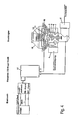
- FIG. 1 A second embodiment of the invention is shown in FIG.
- the valve device here comprises a pneumatic valve 15, a pilot valve 17 and a pressure regulator 18, which is constructed similar to the first embodiment described above.
- the pneumatic valve 15 is coupled via a movable piston rod 16 with seal holder 14 to the input 4 of the pressure regulator 18. At least the pneumatic valve 15 may be partially or completely integrated into the pressure regulator 18.
- the electronic control of the valve device is carried out as in the first embodiment.
- Switched here is the pilot valve 17, which is bistable 3/2-way valve is formed.
- the energy for the switching process is taken from the bus, without the need for an additional power supply.
- the pneumatic valve 15 In the normal state, the pneumatic valve 15 is opened, so that the gas flow to the consumer is not interrupted. By switching the pilot valve 17, the supply pressure, which is present at the input 4 of the pressure regulator 18, is applied to the pneumatic valve 15. By actuating the pneumatic valve 15, the gas supply to the consumer is then interrupted in the pressure regulator 18.
- the maximum stroke of the pneumatic valve 15 must be so large in the open state (normal state) that the flow in the pressure regulator 18 is not or only slightly affected.
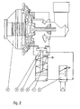
- FIG. 3 shows a third embodiment of the invention, which is very similar to the previously described second embodiment, but in which no pressure regulator is used.
- the device with the pilot valve 17 and the pneumatic valve 15 is attached directly to the supply line. After switching the pilot valve 17, the pneumatic valve 15 itself provides for the interruption of the gas supply.
- FIG. 4 shows a fourth embodiment based on the first embodiment.
- the gas pressure regulator 18 is constructed here somewhat differently and additionally equipped with a vacuum shut-off. In the case of a pressure drop in the consumer line, which occurs, for example, in the event of a leak (line break, accidentally open consumption point, etc.), the pressure regulator 18 automatically shuts off the gas supply.
- bistable valve 17 of the valve device is controllable by means of an external signal. In the event of a power failure, the position of the bistable valve 17 remains unchanged.
- valve 17 can also be switched as a result of an external signal of a sensor, in particular a gas or smoke sensor.
Abstract
Description
Die Erfindung betrifft eine Ventilvorrichtung zur Unterbrechung der Gaszufuhr einer Versorgungsleitung.The invention relates to a valve device for interrupting the gas supply of a supply line.
Gasdruckregler (optional mit Sicherheitsventil) sind bekannt. Sie werden zwischen Gasversorgungsleitung und Endverbraucher aus Sicherheitsgründen installiert. Die Funktion besteht darin, den Gasdruck auf der Endverbraucherseite bei unterschiedlichen Durchflüssen konstant zu halten und Druckschwankungen in der Versorgungsleitung auszugleichen. Außerdem wird bei zu hohem Eingangsdruck die Gaszufuhr durch die Überdruckabschaltung des Gasdruckreglers unterbrochen.Gas pressure regulators (optional with safety valve) are known. They are installed between the gas supply line and the end user for safety reasons. The function is to keep the gas pressure on the consumer side at different flow rates constant and to compensate for pressure fluctuations in the supply line. In addition, at too high inlet pressure, the gas supply is interrupted by the overpressure shutdown of the gas pressure regulator.
Aufgabe der Erfindung ist es, eine Ventilvorrichtung zu schaffen, die eine flexiblere Unterbrechung der Gaszufuhr ermöglicht.The object of the invention is to provide a valve device which allows a more flexible interruption of the gas supply.
Zur Lösung dieser Aufgabe wird eine Ventilvorrichtung zur Unterbrechung der Gaszufuhr einer Versorgungsleitung vorgeschlagen, die dadurch gekennzeichnet ist, dass sie ein Ventil umfasst, das mittel eines externen Signals, insbesondere eines elektrischen Signals, steuerbar ist. Die Erfindung beruht auf der Erkenntnis, dass mit einem rein mechanisch arbeitenden Druckregler die Gaszufuhr nur bei Vorliegen eines Überdrucks in der Gasversorgungsleitung unterbrochen werden kann, wobei der Grenzwert für den Überdruck vom verwendeten Druckregler abhängt. Mit der erfindungsgemäßen Ventilvorrichtung ist es dagegen jederzeit möglich, die Gaszufuhr zu unterbrechen, wenn bestimmte Abschaltbedingungen vorliegen. Die Abschaltbedingungen können vorher individuell festgelegt und ggf. auch geändert werden.To achieve this object, a valve device for interrupting the gas supply of a supply line is proposed, which is characterized in that it comprises a valve which is controllable by means of an external signal, in particular an electrical signal. The invention is based on the finding that with a purely mechanically operating pressure regulator, the gas supply can be interrupted only in the presence of an overpressure in the gas supply line, wherein the limit value for the overpressure depends on the pressure regulator used. With the valve device according to the invention, however, it is always possible to interrupt the gas supply when certain shutdown conditions are present. The switch-off conditions can be set individually beforehand and possibly also changed.
Gemäß den bevorzugten Ausführungsformen der Erfindung ist das Ventil an einen Bus angeschlossen. Das Ventil kann ohne zusätzliche Energieversorgung durch die vom Bus bereitgestellte Energie geschaltet werden.According to the preferred embodiments of the invention, the valve is connected to a bus. The valve can be switched without additional power supply by the energy provided by the bus.
Vorzugsweise ist das Ventil ein bistabiles Ventil, insbesondere ein bistabiles 3/2-Wege-Ventil. Die Verwendung eines bistabilen Ventils hat den Vorteil, daß bei einem Stromausfall die Position des Ventils unverändert bleibt.Preferably, the valve is a bistable valve, in particular a bistable 3/2-way valve. The use of a bistable valve has the advantage that in the event of a power failure, the position of the valve remains unchanged.
Erfolgt die Unterbrechung der Gaszufuhr durch Absperrung einer Hauptzufuhrleitung ist hierfür in der Regel eine große Kraft notwendig. Deshalb sieht die Erfindung für diesen Fall einen in die Versorgungsleitung eingefügten Druckregler vor, wobei das Ventil an den Druckregler angeschlossen ist. Mit dem Druckregler kann der hohe Energieaufwand zum Schließen der Leitung bewerkstelligt werden, indem die vorhandene Überdruckabschaltung eines Gasdruckreglers genutzt wird. Die erfindungsgemäße Funktionalität (Sperren bei festgestelltem Bedarf) ist durch das extern steuerbare, an den Druckregler angeschlossene Ventil gewährleistet.If the interruption of the gas supply by blocking a main supply line this is usually a large force necessary. Therefore, the invention provides for this case, a pressure regulator inserted into the supply line, wherein the valve is connected to the pressure regulator. With the pressure regulator, the high energy consumption for closing the line can be accomplished by the existing overpressure shutdown of a gas pressure regulator is used. The functionality according to the invention (locking in case of a determined need) is ensured by the externally controllable, connected to the pressure regulator valve.
Gemäß einer Weiterbildung der Erfindung ist der Druckregler mit einer Unterdruckabschaltung ausgestattet, die durch die Ventilvorrichtung ausgelöst werden kann.According to one embodiment of the invention, the pressure regulator is equipped with a vacuum shut-off, which can be triggered by the valve device.
Bei Verwendung eines Druckreglers ist es zweckmäßig, einen ersten Anschluss (Eingang) des Ventils mit einer Zuleitung der Versorgungsleitung, einen zweiten Anschluss (Arbeitsanschluss) des Ventils mit einer Druckregelkammer des Druckreglers und einen dritten Anschluss (Entlüftung) des Ventils mit einem Ausgang des Druckreglers zu verbinden.When using a pressure regulator, it is convenient to a first port (input) of the valve with a supply line, a second port (working port) of the valve with a pressure control chamber of the pressure regulator and a third port (vent) of the valve with an output of the pressure regulator connect.
In einem ersten Schaltzustand (Normalzustand) können dann der zweite - Anschluss und der dritte Anschluss des Ventils und in einem zweiten Schaltzustand (Sperrzustand) der erste Anschluss und der zweite Anschluss des Ventils verbunden werden.In a first switching state (normal state), the second connection and the third connection of the valve and in a second switching state (blocking state) the first connection and the second connection of the valve can then be connected.
Alternativ kann vorgesehen sein, die Druckregelkammer des Druckreglers über das Ventil zu entlüften.Alternatively it can be provided to vent the pressure control chamber of the pressure regulator via the valve.
Gemäß einer anderen Ausführungsform ist das Ventil ein Vorsteuerventil zur Betätigung des Pneumatikventils, das über eine bewegliche Kolbenstange an einen Druckregler angekoppelt sein kann. Wenigstens das Pneumatikventil kann in den Druckregler integriert sein.According to another embodiment, the valve is a pilot valve for actuating the pneumatic valve, which may be coupled via a movable piston rod to a pressure regulator. At least the pneumatic valve can be integrated in the pressure regulator.
Das Pneumatikventil kann auch direkt in der Versorgungsleitung angebracht werden und dort die Unterbrechung der Gaszufuhr bewerkstelligen.The pneumatic valve can also be mounted directly in the supply line and manage the interruption of the gas supply.
Die Unterbrechung der Gaszufuhr kann aufgrund des extern steuerbaren Ventils nicht nur bei Vorliegen eines Überdrucks, sondern auch aufgrund anderer Umstände gesperrt werden. Beispielsweise kann das externe Signal von einem Sensor, insbesondere einem Gas- oder Rauchsensor, bereitgestellt werden.The interruption of the gas supply can be locked due to the externally controllable valve not only in the presence of an overpressure, but also due to other circumstances. For example, the external signal can be provided by a sensor, in particular a gas or smoke sensor.
Weitere Merkmale und Vorteile der Erfindung ergeben sich aus der nachfolgenden Beschreibung bevorzugter Ausführungsformen unter Bezugnahme auf die beigefügten Zeichnungen. In den Zeichnungen zeigen:
Figur 1 eine erste Ausführungsform der erfindungsgemäßen Ventilvorrichtung;Figur 2 eine zweite Ausführungsform der erfindungsgemäßen Ventilvorrichtung;Figur 3 eine dritte Ausführungsform der erfindungsgemäßen Ventilvorrichtung; undFigur 4 eine vierte Ausführungsform der erfindungsgemäßen Ventilvorrichtung.
- Figure 1 shows a first embodiment of the valve device according to the invention;
- Figure 2 shows a second embodiment of the valve device according to the invention;
- 3 shows a third embodiment of the valve device according to the invention; and
- Figure 4 shows a fourth embodiment of the valve device according to the invention.
In Figur 1 ist eine erste Ausführungsform der erfindungsgemäßen Ventilvorrichtung dargestellt. Die Vorrichtung umfasst einen in eine Gasversorgungsleitung eingefügten Druckregler 18 und ein an den Druckregler 18 angeschlossenes Schaltventil in Form eines bistabilen 3/2-Wege-Ventils 17.FIG. 1 shows a first embodiment of the valve device according to the invention. The device comprises a
Die Steuerung des Ventils 17 erfolgt über eine Elektronik. Gemäß der Darstellung in Figur 1 kann die Elektronik in eine Kontrolleinheit und eine über einen Bus mit dieser verbundenen Ventilelektronik aufgeteilt werden. Die vom Bus zur Verfügung gestellte Leistung ist auf 12 V und 1,5 mA (= 18 mW) begrenzt. Die Ventilelektronik ist in der Lage, diese Energie zu speichern. In Reaktion auf ein zusätzliches, externes Steuersignal, das in der Regel von der Kontrolleinheit ausgegeben wird, schaltet die Ventilelektronik das Ventil 17 unter Verwendung der zuvor gespeicherten Energie. Außer der Versorgung über den Bus wird hierfür keine zusätzliche Energieversorgung benötigt.The control of the
Der bei der Ausführungsform gemäß Figur 1 verwendete Druckregler 18 weist einen mit der Gaszuleitung verbundenen Eingang 4, einen Ausgang 5, eine Ventildichtung 6, einen Ventilsitz 7, einen Bypass 8, eine Spindel 9, eine Druckregelkammer 10, einen Teller 11 und eine Feder 12 auf. Generell kann aber auch ein Druckregler anderer Bauart eingesetzt werden.The
Die Gaszuleitung ist ferner mit dem ersten Anschluss 1 (Eingang) des 3/2-Wege-Ventils 17 verbunden. Die Druckregelkammer 10 des Druckreglers 18 ist mit dem zweiten Anschluss 2 (Arbeitsanschluss) des Ventils 17 verbunden. Der Ausgang 5 des Druckreglers 18 ist mit dem dritten Anschluss 3 (Entlüftung) des 3/2-Wege-Ventils 17 verbunden.The gas supply line is further connected to the first port 1 (input) of the 3/2-
Im Normalzustand sind im 3/2-Wege-Ventil 17 die Anschlüsse 2 und 3 durchverbunden (erster stabiler Zustand). Der Bypass 8 zwischen dem Ausgang 5 und Druckregelkammer 10 des Druckreglers 18 ist verschlossen. Die erfindungsgemäße Vorrichtung erfüllt in diesem Zustand keine besondere Funktion und wirkt wie ein herkömmlicher, in die Gasversorgungsleitung eingefügter Druckregler.In the normal state, the
Wird das 3/2-Wege-Ventil 17 nun infolge eines externen Signals geschaltet (zweiter stabiler Zustand), so verbindet es die Anschlüsse 2 und 1. Damit wird der Versorgungsdruck in die Druckregelkammer 10 des Druckreglers 18 aufgeschaltet. Folglich wird der Teller 11 des Druckreglers 18 gegen die Feder 12 angehoben und schließt über die Spindel 9 den Ventilsitz 7. Dadurch ist die Gaszufuhr zum Verbraucher unterbrochen.If the 3/2-
Das Rückschalten des 3/2-Wege-Ventils 17 erfolgt auf die gleiche Weise, d. h. wiederum in Reaktion auf ein externes Signal und mit Hilfe der aus dem Bus entnommenen Energie. Dies ist möglich, da es sich um ein bistabiles Ventil handelt. Nach dem Rückschalten befindet sich der Druckregler 18 wieder im Normalzustand.The switching back of the 3/2-
Alternativ zu dieser Lösung kann die Druckregelkammer 10 des Druckreglers 18 über das bistabile 3/2-Wege-Ventil 17 entlüftet werden, um den Teller 11 durch die Kraft der Feder 12 abzusenken und den Ventilsitz 7 freizugeben. Gleichzeitig wird der Bypass 8 verschlossen.Alternatively to this solution, the
Eine zweite Ausführungsform der Erfindung ist in Figur 2 dargestellt. Die Ventilvorrichtung umfasst hier ein Pneumatikventil 15, ein Vorsteuerventil 17 und einen Druckregler 18, der ähnlich wie bei der zuvor beschriebenen ersten Ausführungsform aufgebaut ist. Das Pneumatikventil 15 ist über eine bewegliche Kolbenstange 16 mit Dichtungshalter 14 an den Eingang 4 des Druckreglers 18 angekoppelt. Zumindest das Pneumatikventil 15 kann teilweise oder vollständig in den Druckregler 18 integriert sein.A second embodiment of the invention is shown in FIG. The valve device here comprises a
Die elektronische Steuerung der Ventilvorrichtung erfolgt wie bei der ersten Ausführungsform. Geschaltet wird hier das Vorsteuerventil 17, das als bistabiles 3/2-Wege-Ventil ausgebildet ist. Die Energie für den Schaltvorgang wird dem Bus entnommen, ohne dass eine zusätzliche Spannungsversorgung nötig ist.The electronic control of the valve device is carried out as in the first embodiment. Switched here is the
Im Normalzustand ist das Pneumatikventil 15 geöffnet, so dass der Gasstrom zum Verbraucher nicht unterbrochen ist. Durch Schalten des Vorsteuerventils 17 wird der Versorgungsdruck, der am Eingang 4 des Druckreglers 18 ansteht, auf das Pneumatikventil 15 gegeben. Durch die Betätigung des Pneumatikventils 15 wird dann im Druckregler 18 die Gaszufuhr zum Verbraucher unterbrochen.In the normal state, the
Der maximale Hub des Pneumatikventils 15 muss im geöffneten Zustand (Normalzustand) so groß sein, dass der Durchfluss im Druckregler 18 gar nicht oder nur geringfügig beeinträchtigt wird.The maximum stroke of the
In Figur 3 ist eine dritte Ausführungsform der Erfindung gezeigt, die der zuvor beschriebenen zweiten Ausführungsform sehr ähnlich ist, bei der jedoch kein Druckregler zum Einsatz kommt. Hier ist die Vorrichtung mit dem Vorsteuerventil 17 und dem Pneumatikventil 15 direkt an der Versorgungsleitung angebracht. Nach dem Schalten des Vorsteuerventils 17 sorgt das Pneumatikventil 15 selbst für die Unterbrechung der Gaszufuhr.FIG. 3 shows a third embodiment of the invention, which is very similar to the previously described second embodiment, but in which no pressure regulator is used. Here, the device with the
In Figur 4 ist eine vierte Ausführungsform dargestellt, die auf der ersten Ausführungsform basiert. Der Gasdruckregler 18 ist hier etwas anders aufgebaut und zusätzlich mit einer Unterdruckabschaltung ausgestattet. Bei einem Druckabfall in der Verbraucherleitung, der beispielsweise im Falle einer Leckage (Leitungsbruch, versehentlich offene Verbrauchsstelle u.ä.) auftritt, schaltet der Druckregler 18 die Gaszufuhr automatisch ab.FIG. 4 shows a fourth embodiment based on the first embodiment. The
Allen Ausführungsformen ist gemeinsam, dass das bistabile Ventil 17 der Ventilvorrichtung mittel eines externen Signals steuerbar ist. Bei einem Stromausfall bleibt die Position des bistabilen Ventils 17 unverändert.All embodiments have in common that the
Zur Erhöhung der Sicherheit für den Verbraucher kann das Ventil 17 auch infolge eines externen Signals eines Sensors, insbesondere eines Gas- oder Rauchsensors, geschaltet werden.To increase safety for the consumer, the
- 1, 2, 31, 2, 3
- Ein/Ausgänge des bistabilen 312-Wege-VentilsInputs / outputs of the bistable 312-way valve
- 44
- Eingang DruckreglerInput pressure regulator
- 55
- Ausgang DruckreglerOutput pressure regulator
- 66
- Ventildichtungvalve seal
- 77
- Ventilsitzvalve seat
- 88th
- Bypassbypass
- 99
- Spindelspindle
- 1010
- DruckregelkammerPressure control chamber
- 1111
- TellerPlate
- 1212
- Federfeather
- 1414
- Dichtungshalterseal holder
- 1515
- Pneumatikventilpneumatic valve
- 1616
- Kolbenstangepiston rod
- 1717
-
bistabiles 3/2-Wege-Ventil
Bistable 3/2-way valve - 1818
- Druckreglerpressure regulator
Claims (16)
Applications Claiming Priority (2)
| Application Number | Priority Date | Filing Date | Title |
|---|---|---|---|
| DE102006054430 | 2006-11-16 | ||
| DE102007009288A DE102007009288A1 (en) | 2006-11-16 | 2007-02-26 | Valve device for interrupting the gas supply of a supply line |
Publications (3)
| Publication Number | Publication Date |
|---|---|
| EP1923631A2 true EP1923631A2 (en) | 2008-05-21 |
| EP1923631A3 EP1923631A3 (en) | 2011-07-06 |
| EP1923631B1 EP1923631B1 (en) | 2014-09-03 |
Family
ID=39032170
Family Applications (1)
| Application Number | Title | Priority Date | Filing Date |
|---|---|---|---|
| EP07022285.6A Not-in-force EP1923631B1 (en) | 2006-11-16 | 2007-11-16 | Valve device for interrupting the gas supply in a feed line |
Country Status (2)
| Country | Link |
|---|---|
| EP (1) | EP1923631B1 (en) |
| DE (1) | DE102007009288A1 (en) |
Cited By (1)
| Publication number | Priority date | Publication date | Assignee | Title |
|---|---|---|---|---|
| NL2023052B1 (en) | 2019-05-02 | 2020-11-23 | Gavilar B V | Method and device for closing a gas pressure control device |
Citations (9)
| Publication number | Priority date | Publication date | Assignee | Title |
|---|---|---|---|---|
| DE2111343B1 (en) * | 1971-03-10 | 1972-04-27 | Kromschroeder Ag G | Arrangement for performing a leak test of fuel shut-off devices connected in series in the fuel line to a fire station |
| EP0177620A1 (en) * | 1984-01-26 | 1986-04-16 | GebràDer Sulzer Aktiengesellschaft | Pressure fluid-actuated valve |
| US5126934A (en) * | 1989-06-09 | 1992-06-30 | Smart House, L.P. | Gas distribution system |
| US5244179A (en) * | 1992-08-21 | 1993-09-14 | Sloan Valve Company | Diaphragm stop for sensor-operated, battery-powered flush valve |
| US5457594A (en) * | 1992-09-11 | 1995-10-10 | Festo Kg | Electropneumatic control device |
| EP0751350A2 (en) * | 1995-06-29 | 1997-01-02 | ELCO KLÖCKNER HEIZTECHNIK GmbH | Combustion plant and method for controlling and/or monitoring a combustion plant |
| DE19729229A1 (en) * | 1997-07-09 | 1999-01-14 | Ruhrgas Ag | Shutting down fluid supply systems in emergency |
| EP1382910A2 (en) * | 2002-07-18 | 2004-01-21 | Honeywell B.V. | Control device for gas burners |
| DE102005010684B3 (en) * | 2005-03-09 | 2006-05-11 | Honeywell B.V. | Control equipment for gas burner has safety device integrated into fourth gas line connected with third gas area and main valve closes when safety device exceeds given temperature |
Family Cites Families (6)
| Publication number | Priority date | Publication date | Assignee | Title |
|---|---|---|---|---|
| DE3633312A1 (en) * | 1986-09-30 | 1988-04-07 | Rexroth Mannesmann Gmbh | Magnetically operated valve, acting, in particular, as a safety valve |
| DE3925686C2 (en) * | 1988-08-25 | 1994-12-08 | Hydraulik Ring Gmbh | Device for continuously influencing a fluid flow in a valve |
| DE3931962A1 (en) * | 1989-09-25 | 1991-04-04 | Rexroth Mannesmann Gmbh | CONTROL ELECTRONICS FOR AN ELECTRICALLY ADJUSTABLE ACTUATOR |
| DE3936619A1 (en) * | 1989-11-03 | 1991-05-08 | Man Nutzfahrzeuge Ag | METHOD FOR INJECTING A FUEL INTO THE COMBUSTION CHAMBER OF AN AIR COMPRESSING, SELF-IGNITION ENGINE, AND APPARATUS FOR CARRYING OUT THIS METHOD |
| US5445185A (en) * | 1993-04-05 | 1995-08-29 | Ford Motor Company | Piezoelectric fluid control valve |
| DE19821768C2 (en) * | 1998-05-14 | 2000-09-07 | Siemens Ag | Dosing device and dosing method |
-
2007
- 2007-02-26 DE DE102007009288A patent/DE102007009288A1/en not_active Withdrawn
- 2007-11-16 EP EP07022285.6A patent/EP1923631B1/en not_active Not-in-force
Patent Citations (9)
| Publication number | Priority date | Publication date | Assignee | Title |
|---|---|---|---|---|
| DE2111343B1 (en) * | 1971-03-10 | 1972-04-27 | Kromschroeder Ag G | Arrangement for performing a leak test of fuel shut-off devices connected in series in the fuel line to a fire station |
| EP0177620A1 (en) * | 1984-01-26 | 1986-04-16 | GebràDer Sulzer Aktiengesellschaft | Pressure fluid-actuated valve |
| US5126934A (en) * | 1989-06-09 | 1992-06-30 | Smart House, L.P. | Gas distribution system |
| US5244179A (en) * | 1992-08-21 | 1993-09-14 | Sloan Valve Company | Diaphragm stop for sensor-operated, battery-powered flush valve |
| US5457594A (en) * | 1992-09-11 | 1995-10-10 | Festo Kg | Electropneumatic control device |
| EP0751350A2 (en) * | 1995-06-29 | 1997-01-02 | ELCO KLÖCKNER HEIZTECHNIK GmbH | Combustion plant and method for controlling and/or monitoring a combustion plant |
| DE19729229A1 (en) * | 1997-07-09 | 1999-01-14 | Ruhrgas Ag | Shutting down fluid supply systems in emergency |
| EP1382910A2 (en) * | 2002-07-18 | 2004-01-21 | Honeywell B.V. | Control device for gas burners |
| DE102005010684B3 (en) * | 2005-03-09 | 2006-05-11 | Honeywell B.V. | Control equipment for gas burner has safety device integrated into fourth gas line connected with third gas area and main valve closes when safety device exceeds given temperature |
Cited By (1)
| Publication number | Priority date | Publication date | Assignee | Title |
|---|---|---|---|---|
| NL2023052B1 (en) | 2019-05-02 | 2020-11-23 | Gavilar B V | Method and device for closing a gas pressure control device |
Also Published As
| Publication number | Publication date |
|---|---|
| EP1923631A3 (en) | 2011-07-06 |
| EP1923631B1 (en) | 2014-09-03 |
| DE102007009288A1 (en) | 2008-05-21 |
Similar Documents
| Publication | Publication Date | Title |
|---|---|---|
| EP1382910B1 (en) | Control device for gas burners | |
| EP0616941B1 (en) | System to avoid the self-opening of a door or a cover not correctly closed and locked, in an aircraft fuselage | |
| DE102016008107A1 (en) | tank valve | |
| DE102006013538B4 (en) | Pressure control device for an emergency oxygen supply system in an aircraft | |
| EP2283900B1 (en) | Emergency oxygen supply device | |
| DE112010000058T5 (en) | Valve system for vehicle high-pressure tank | |
| EP2237128B1 (en) | Pilot operated proportional pressure valve assembly with electronic pre-controller | |
| DE3036789C2 (en) | Pressure relief device | |
| DE2657854A1 (en) | GAS PRESSURE REGULATOR | |
| WO2017088944A1 (en) | Tank valve | |
| EP0810136A1 (en) | Pressure installation | |
| EP0433791A1 (en) | Actuator for a feeding valve | |
| EP1923631A2 (en) | Valve device for interrupting the gas supply in a feed line | |
| DE102014005454A1 (en) | Shut-off valve and fuel cell system | |
| EP1447321B1 (en) | Submarine wit a safety valve in a gas supply line | |
| DE10119339B4 (en) | Fuel cell system and method for pressure regulation in fuel cell systems and use of the fuel cell system | |
| DE3633660C2 (en) | ||
| DE4320937A1 (en) | Actuator for a control valve | |
| DE102014001375A1 (en) | Device for supplying an energy system | |
| EP0758063B1 (en) | Starting valve for pneumatic systems | |
| EP0492068B1 (en) | Compressed air system with a high pressure part and a low pressure part | |
| EP2908055B1 (en) | Gas valve with integrated air pressure monitor | |
| DE102013205961A1 (en) | Safety system for a hydraulic circuit | |
| DE10311449B4 (en) | Closing device for a fire section | |
| DE4004406A1 (en) | Re-switchable signal generator for safety function tripping - generates tripping signal in two channels by different pressure states, respectively |
Legal Events
| Date | Code | Title | Description |
|---|---|---|---|
| PUAI | Public reference made under article 153(3) epc to a published international application that has entered the european phase |
Free format text: ORIGINAL CODE: 0009012 |
|
| AK | Designated contracting states |
Kind code of ref document: A2 Designated state(s): AT BE BG CH CY CZ DE DK EE ES FI FR GB GR HU IE IS IT LI LT LU LV MC MT NL PL PT RO SE SI SK TR |
|
| AX | Request for extension of the european patent |
Extension state: AL BA HR MK RS |
|
| RAP1 | Party data changed (applicant data changed or rights of an application transferred) |
Owner name: BUERKERT WERKE GMBH |
|
| PUAL | Search report despatched |
Free format text: ORIGINAL CODE: 0009013 |
|
| AK | Designated contracting states |
Kind code of ref document: A3 Designated state(s): AT BE BG CH CY CZ DE DK EE ES FI FR GB GR HU IE IS IT LI LT LU LV MC MT NL PL PT RO SE SI SK TR |
|
| AX | Request for extension of the european patent |
Extension state: AL BA HR MK RS |
|
| 17P | Request for examination filed |
Effective date: 20111031 |
|
| 17Q | First examination report despatched |
Effective date: 20120123 |
|
| AKX | Designation fees paid |
Designated state(s): AT BE BG CH CY CZ DE DK EE ES FI FR GB GR HU IE IS IT LI LT LU LV MC MT NL PL PT RO SE SI SK TR |
|
| GRAP | Despatch of communication of intention to grant a patent |
Free format text: ORIGINAL CODE: EPIDOSNIGR1 |
|
| INTG | Intention to grant announced |
Effective date: 20140324 |
|
| GRAS | Grant fee paid |
Free format text: ORIGINAL CODE: EPIDOSNIGR3 |
|
| GRAA | (expected) grant |
Free format text: ORIGINAL CODE: 0009210 |
|
| AK | Designated contracting states |
Kind code of ref document: B1 Designated state(s): AT BE BG CH CY CZ DE DK EE ES FI FR GB GR HU IE IS IT LI LT LU LV MC MT NL PL PT RO SE SI SK TR |
|
| REG | Reference to a national code |
Ref country code: GB Ref legal event code: FG4D Free format text: NOT ENGLISH |
|
| REG | Reference to a national code |
Ref country code: AT Ref legal event code: REF Ref document number: 685822 Country of ref document: AT Kind code of ref document: T Effective date: 20140915 Ref country code: CH Ref legal event code: EP |
|
| REG | Reference to a national code |
Ref country code: IE Ref legal event code: FG4D Free format text: LANGUAGE OF EP DOCUMENT: GERMAN |
|
| REG | Reference to a national code |
Ref country code: DE Ref legal event code: R096 Ref document number: 502007013409 Country of ref document: DE Effective date: 20141009 |
|
| PG25 | Lapsed in a contracting state [announced via postgrant information from national office to epo] |
Ref country code: GR Free format text: LAPSE BECAUSE OF FAILURE TO SUBMIT A TRANSLATION OF THE DESCRIPTION OR TO PAY THE FEE WITHIN THE PRESCRIBED TIME-LIMIT Effective date: 20141204 Ref country code: LT Free format text: LAPSE BECAUSE OF FAILURE TO SUBMIT A TRANSLATION OF THE DESCRIPTION OR TO PAY THE FEE WITHIN THE PRESCRIBED TIME-LIMIT Effective date: 20140903 Ref country code: SE Free format text: LAPSE BECAUSE OF FAILURE TO SUBMIT A TRANSLATION OF THE DESCRIPTION OR TO PAY THE FEE WITHIN THE PRESCRIBED TIME-LIMIT Effective date: 20140903 Ref country code: FI Free format text: LAPSE BECAUSE OF FAILURE TO SUBMIT A TRANSLATION OF THE DESCRIPTION OR TO PAY THE FEE WITHIN THE PRESCRIBED TIME-LIMIT Effective date: 20140903 Ref country code: ES Free format text: LAPSE BECAUSE OF FAILURE TO SUBMIT A TRANSLATION OF THE DESCRIPTION OR TO PAY THE FEE WITHIN THE PRESCRIBED TIME-LIMIT Effective date: 20140903 |
|
| REG | Reference to a national code |
Ref country code: NL Ref legal event code: VDEP Effective date: 20140903 |
|
| REG | Reference to a national code |
Ref country code: LT Ref legal event code: MG4D |
|
| PG25 | Lapsed in a contracting state [announced via postgrant information from national office to epo] |
Ref country code: LV Free format text: LAPSE BECAUSE OF FAILURE TO SUBMIT A TRANSLATION OF THE DESCRIPTION OR TO PAY THE FEE WITHIN THE PRESCRIBED TIME-LIMIT Effective date: 20140903 Ref country code: CY Free format text: LAPSE BECAUSE OF FAILURE TO SUBMIT A TRANSLATION OF THE DESCRIPTION OR TO PAY THE FEE WITHIN THE PRESCRIBED TIME-LIMIT Effective date: 20140903 |
|
| PG25 | Lapsed in a contracting state [announced via postgrant information from national office to epo] |
Ref country code: NL Free format text: LAPSE BECAUSE OF FAILURE TO SUBMIT A TRANSLATION OF THE DESCRIPTION OR TO PAY THE FEE WITHIN THE PRESCRIBED TIME-LIMIT Effective date: 20140903 |
|
| PG25 | Lapsed in a contracting state [announced via postgrant information from national office to epo] |
Ref country code: CZ Free format text: LAPSE BECAUSE OF FAILURE TO SUBMIT A TRANSLATION OF THE DESCRIPTION OR TO PAY THE FEE WITHIN THE PRESCRIBED TIME-LIMIT Effective date: 20140903 Ref country code: EE Free format text: LAPSE BECAUSE OF FAILURE TO SUBMIT A TRANSLATION OF THE DESCRIPTION OR TO PAY THE FEE WITHIN THE PRESCRIBED TIME-LIMIT Effective date: 20140903 Ref country code: RO Free format text: LAPSE BECAUSE OF FAILURE TO SUBMIT A TRANSLATION OF THE DESCRIPTION OR TO PAY THE FEE WITHIN THE PRESCRIBED TIME-LIMIT Effective date: 20140903 Ref country code: SK Free format text: LAPSE BECAUSE OF FAILURE TO SUBMIT A TRANSLATION OF THE DESCRIPTION OR TO PAY THE FEE WITHIN THE PRESCRIBED TIME-LIMIT Effective date: 20140903 Ref country code: PT Free format text: LAPSE BECAUSE OF FAILURE TO SUBMIT A TRANSLATION OF THE DESCRIPTION OR TO PAY THE FEE WITHIN THE PRESCRIBED TIME-LIMIT Effective date: 20150105 Ref country code: IS Free format text: LAPSE BECAUSE OF FAILURE TO SUBMIT A TRANSLATION OF THE DESCRIPTION OR TO PAY THE FEE WITHIN THE PRESCRIBED TIME-LIMIT Effective date: 20150103 |
|
| PG25 | Lapsed in a contracting state [announced via postgrant information from national office to epo] |
Ref country code: PL Free format text: LAPSE BECAUSE OF FAILURE TO SUBMIT A TRANSLATION OF THE DESCRIPTION OR TO PAY THE FEE WITHIN THE PRESCRIBED TIME-LIMIT Effective date: 20140903 |
|
| REG | Reference to a national code |
Ref country code: DE Ref legal event code: R097 Ref document number: 502007013409 Country of ref document: DE |
|
| PG25 | Lapsed in a contracting state [announced via postgrant information from national office to epo] |
Ref country code: MC Free format text: LAPSE BECAUSE OF FAILURE TO SUBMIT A TRANSLATION OF THE DESCRIPTION OR TO PAY THE FEE WITHIN THE PRESCRIBED TIME-LIMIT Effective date: 20140903 Ref country code: LU Free format text: LAPSE BECAUSE OF FAILURE TO SUBMIT A TRANSLATION OF THE DESCRIPTION OR TO PAY THE FEE WITHIN THE PRESCRIBED TIME-LIMIT Effective date: 20141116 Ref country code: BE Free format text: LAPSE BECAUSE OF NON-PAYMENT OF DUE FEES Effective date: 20141130 |
|
| REG | Reference to a national code |
Ref country code: CH Ref legal event code: PL |
|
| PLBE | No opposition filed within time limit |
Free format text: ORIGINAL CODE: 0009261 |
|
| STAA | Information on the status of an ep patent application or granted ep patent |
Free format text: STATUS: NO OPPOSITION FILED WITHIN TIME LIMIT |
|
| PG25 | Lapsed in a contracting state [announced via postgrant information from national office to epo] |
Ref country code: DK Free format text: LAPSE BECAUSE OF FAILURE TO SUBMIT A TRANSLATION OF THE DESCRIPTION OR TO PAY THE FEE WITHIN THE PRESCRIBED TIME-LIMIT Effective date: 20140903 Ref country code: LI Free format text: LAPSE BECAUSE OF NON-PAYMENT OF DUE FEES Effective date: 20141130 Ref country code: CH Free format text: LAPSE BECAUSE OF NON-PAYMENT OF DUE FEES Effective date: 20141130 |
|
| 26N | No opposition filed |
Effective date: 20150604 |
|
| GBPC | Gb: european patent ceased through non-payment of renewal fee |
Effective date: 20141203 |
|
| REG | Reference to a national code |
Ref country code: IE Ref legal event code: MM4A |
|
| REG | Reference to a national code |
Ref country code: FR Ref legal event code: ST Effective date: 20150731 |
|
| PG25 | Lapsed in a contracting state [announced via postgrant information from national office to epo] |
Ref country code: IT Free format text: LAPSE BECAUSE OF FAILURE TO SUBMIT A TRANSLATION OF THE DESCRIPTION OR TO PAY THE FEE WITHIN THE PRESCRIBED TIME-LIMIT Effective date: 20140903 |
|
| PG25 | Lapsed in a contracting state [announced via postgrant information from national office to epo] |
Ref country code: IE Free format text: LAPSE BECAUSE OF NON-PAYMENT OF DUE FEES Effective date: 20141116 Ref country code: GB Free format text: LAPSE BECAUSE OF NON-PAYMENT OF DUE FEES Effective date: 20141203 |
|
| PG25 | Lapsed in a contracting state [announced via postgrant information from national office to epo] |
Ref country code: SI Free format text: LAPSE BECAUSE OF FAILURE TO SUBMIT A TRANSLATION OF THE DESCRIPTION OR TO PAY THE FEE WITHIN THE PRESCRIBED TIME-LIMIT Effective date: 20140903 Ref country code: FR Free format text: LAPSE BECAUSE OF NON-PAYMENT OF DUE FEES Effective date: 20141201 |
|
| REG | Reference to a national code |
Ref country code: AT Ref legal event code: MM01 Ref document number: 685822 Country of ref document: AT Kind code of ref document: T Effective date: 20141116 |
|
| PG25 | Lapsed in a contracting state [announced via postgrant information from national office to epo] |
Ref country code: AT Free format text: LAPSE BECAUSE OF NON-PAYMENT OF DUE FEES Effective date: 20141116 |
|
| PG25 | Lapsed in a contracting state [announced via postgrant information from national office to epo] |
Ref country code: BG Free format text: LAPSE BECAUSE OF FAILURE TO SUBMIT A TRANSLATION OF THE DESCRIPTION OR TO PAY THE FEE WITHIN THE PRESCRIBED TIME-LIMIT Effective date: 20140903 |
|
| PG25 | Lapsed in a contracting state [announced via postgrant information from national office to epo] |
Ref country code: HU Free format text: LAPSE BECAUSE OF FAILURE TO SUBMIT A TRANSLATION OF THE DESCRIPTION OR TO PAY THE FEE WITHIN THE PRESCRIBED TIME-LIMIT; INVALID AB INITIO Effective date: 20071116 Ref country code: MT Free format text: LAPSE BECAUSE OF FAILURE TO SUBMIT A TRANSLATION OF THE DESCRIPTION OR TO PAY THE FEE WITHIN THE PRESCRIBED TIME-LIMIT Effective date: 20140903 Ref country code: TR Free format text: LAPSE BECAUSE OF FAILURE TO SUBMIT A TRANSLATION OF THE DESCRIPTION OR TO PAY THE FEE WITHIN THE PRESCRIBED TIME-LIMIT Effective date: 20140903 |
|
| PGFP | Annual fee paid to national office [announced via postgrant information from national office to epo] |
Ref country code: DE Payment date: 20191126 Year of fee payment: 13 |
|
| REG | Reference to a national code |
Ref country code: DE Ref legal event code: R119 Ref document number: 502007013409 Country of ref document: DE |
|
| PG25 | Lapsed in a contracting state [announced via postgrant information from national office to epo] |
Ref country code: DE Free format text: LAPSE BECAUSE OF NON-PAYMENT OF DUE FEES Effective date: 20210601 |
|
| P01 | Opt-out of the competence of the unified patent court (upc) registered |
Effective date: 20230523 |