EP1925271A1 - Intervertebral implant - Google Patents
Intervertebral implant Download PDFInfo
- Publication number
- EP1925271A1 EP1925271A1 EP06024186A EP06024186A EP1925271A1 EP 1925271 A1 EP1925271 A1 EP 1925271A1 EP 06024186 A EP06024186 A EP 06024186A EP 06024186 A EP06024186 A EP 06024186A EP 1925271 A1 EP1925271 A1 EP 1925271A1
- Authority
- EP
- European Patent Office
- Prior art keywords
- intervertebral implant
- implant according
- instrument
- cage
- portions
- Prior art date
- Legal status (The legal status is an assumption and is not a legal conclusion. Google has not performed a legal analysis and makes no representation as to the accuracy of the status listed.)
- Granted
Links
- 239000007943 implant Substances 0.000 title claims abstract description 51
- 230000008878 coupling Effects 0.000 claims abstract description 22
- 238000010168 coupling process Methods 0.000 claims abstract description 22
- 238000005859 coupling reaction Methods 0.000 claims abstract description 22
- 238000004873 anchoring Methods 0.000 claims description 4
- 230000002093 peripheral effect Effects 0.000 claims description 4
- 230000004927 fusion Effects 0.000 description 15
- 238000000034 method Methods 0.000 description 6
- 208000031968 Cadaver Diseases 0.000 description 1
- 230000001419 dependent effect Effects 0.000 description 1
- 238000002513 implantation Methods 0.000 description 1
- 230000007170 pathology Effects 0.000 description 1
- 230000037361 pathway Effects 0.000 description 1
Images


Classifications
-
- A—HUMAN NECESSITIES
- A61—MEDICAL OR VETERINARY SCIENCE; HYGIENE
- A61F—FILTERS IMPLANTABLE INTO BLOOD VESSELS; PROSTHESES; DEVICES PROVIDING PATENCY TO, OR PREVENTING COLLAPSING OF, TUBULAR STRUCTURES OF THE BODY, e.g. STENTS; ORTHOPAEDIC, NURSING OR CONTRACEPTIVE DEVICES; FOMENTATION; TREATMENT OR PROTECTION OF EYES OR EARS; BANDAGES, DRESSINGS OR ABSORBENT PADS; FIRST-AID KITS
- A61F2/00—Filters implantable into blood vessels; Prostheses, i.e. artificial substitutes or replacements for parts of the body; Appliances for connecting them with the body; Devices providing patency to, or preventing collapsing of, tubular structures of the body, e.g. stents
- A61F2/02—Prostheses implantable into the body
- A61F2/30—Joints
- A61F2/44—Joints for the spine, e.g. vertebrae, spinal discs
- A61F2/4455—Joints for the spine, e.g. vertebrae, spinal discs for the fusion of spinal bodies, e.g. intervertebral fusion of adjacent spinal bodies, e.g. fusion cages
- A61F2/4465—Joints for the spine, e.g. vertebrae, spinal discs for the fusion of spinal bodies, e.g. intervertebral fusion of adjacent spinal bodies, e.g. fusion cages having a circular or kidney shaped cross-section substantially perpendicular to the axis of the spine
-
- A—HUMAN NECESSITIES
- A61—MEDICAL OR VETERINARY SCIENCE; HYGIENE
- A61F—FILTERS IMPLANTABLE INTO BLOOD VESSELS; PROSTHESES; DEVICES PROVIDING PATENCY TO, OR PREVENTING COLLAPSING OF, TUBULAR STRUCTURES OF THE BODY, e.g. STENTS; ORTHOPAEDIC, NURSING OR CONTRACEPTIVE DEVICES; FOMENTATION; TREATMENT OR PROTECTION OF EYES OR EARS; BANDAGES, DRESSINGS OR ABSORBENT PADS; FIRST-AID KITS
- A61F2/00—Filters implantable into blood vessels; Prostheses, i.e. artificial substitutes or replacements for parts of the body; Appliances for connecting them with the body; Devices providing patency to, or preventing collapsing of, tubular structures of the body, e.g. stents
- A61F2/02—Prostheses implantable into the body
- A61F2/30—Joints
- A61F2/30767—Special external or bone-contacting surface, e.g. coating for improving bone ingrowth
- A61F2/30771—Special external or bone-contacting surface, e.g. coating for improving bone ingrowth applied in original prostheses, e.g. holes or grooves
-
- A—HUMAN NECESSITIES
- A61—MEDICAL OR VETERINARY SCIENCE; HYGIENE
- A61F—FILTERS IMPLANTABLE INTO BLOOD VESSELS; PROSTHESES; DEVICES PROVIDING PATENCY TO, OR PREVENTING COLLAPSING OF, TUBULAR STRUCTURES OF THE BODY, e.g. STENTS; ORTHOPAEDIC, NURSING OR CONTRACEPTIVE DEVICES; FOMENTATION; TREATMENT OR PROTECTION OF EYES OR EARS; BANDAGES, DRESSINGS OR ABSORBENT PADS; FIRST-AID KITS
- A61F2/00—Filters implantable into blood vessels; Prostheses, i.e. artificial substitutes or replacements for parts of the body; Appliances for connecting them with the body; Devices providing patency to, or preventing collapsing of, tubular structures of the body, e.g. stents
- A61F2/02—Prostheses implantable into the body
- A61F2/30—Joints
- A61F2/46—Special tools or methods for implanting or extracting artificial joints, accessories, bone grafts or substitutes, or particular adaptations therefor
- A61F2/4603—Special tools or methods for implanting or extracting artificial joints, accessories, bone grafts or substitutes, or particular adaptations therefor for insertion or extraction of endoprosthetic joints or of accessories thereof
- A61F2/4611—Special tools or methods for implanting or extracting artificial joints, accessories, bone grafts or substitutes, or particular adaptations therefor for insertion or extraction of endoprosthetic joints or of accessories thereof of spinal prostheses
-
- A—HUMAN NECESSITIES
- A61—MEDICAL OR VETERINARY SCIENCE; HYGIENE
- A61F—FILTERS IMPLANTABLE INTO BLOOD VESSELS; PROSTHESES; DEVICES PROVIDING PATENCY TO, OR PREVENTING COLLAPSING OF, TUBULAR STRUCTURES OF THE BODY, e.g. STENTS; ORTHOPAEDIC, NURSING OR CONTRACEPTIVE DEVICES; FOMENTATION; TREATMENT OR PROTECTION OF EYES OR EARS; BANDAGES, DRESSINGS OR ABSORBENT PADS; FIRST-AID KITS
- A61F2/00—Filters implantable into blood vessels; Prostheses, i.e. artificial substitutes or replacements for parts of the body; Appliances for connecting them with the body; Devices providing patency to, or preventing collapsing of, tubular structures of the body, e.g. stents
- A61F2/02—Prostheses implantable into the body
- A61F2/30—Joints
- A61F2002/30001—Additional features of subject-matter classified in A61F2/28, A61F2/30 and subgroups thereof
- A61F2002/30108—Shapes
- A61F2002/3011—Cross-sections or two-dimensional shapes
- A61F2002/30112—Rounded shapes, e.g. with rounded corners
- A61F2002/30133—Rounded shapes, e.g. with rounded corners kidney-shaped or bean-shaped
-
- A—HUMAN NECESSITIES
- A61—MEDICAL OR VETERINARY SCIENCE; HYGIENE
- A61F—FILTERS IMPLANTABLE INTO BLOOD VESSELS; PROSTHESES; DEVICES PROVIDING PATENCY TO, OR PREVENTING COLLAPSING OF, TUBULAR STRUCTURES OF THE BODY, e.g. STENTS; ORTHOPAEDIC, NURSING OR CONTRACEPTIVE DEVICES; FOMENTATION; TREATMENT OR PROTECTION OF EYES OR EARS; BANDAGES, DRESSINGS OR ABSORBENT PADS; FIRST-AID KITS
- A61F2/00—Filters implantable into blood vessels; Prostheses, i.e. artificial substitutes or replacements for parts of the body; Appliances for connecting them with the body; Devices providing patency to, or preventing collapsing of, tubular structures of the body, e.g. stents
- A61F2/02—Prostheses implantable into the body
- A61F2/30—Joints
- A61F2002/30001—Additional features of subject-matter classified in A61F2/28, A61F2/30 and subgroups thereof
- A61F2002/30316—The prosthesis having different structural features at different locations within the same prosthesis; Connections between prosthetic parts; Special structural features of bone or joint prostheses not otherwise provided for
- A61F2002/30329—Connections or couplings between prosthetic parts, e.g. between modular parts; Connecting elements
- A61F2002/30383—Connections or couplings between prosthetic parts, e.g. between modular parts; Connecting elements made by laterally inserting a protrusion, e.g. a rib into a complementarily-shaped groove
- A61F2002/30387—Dovetail connection
-
- A—HUMAN NECESSITIES
- A61—MEDICAL OR VETERINARY SCIENCE; HYGIENE
- A61F—FILTERS IMPLANTABLE INTO BLOOD VESSELS; PROSTHESES; DEVICES PROVIDING PATENCY TO, OR PREVENTING COLLAPSING OF, TUBULAR STRUCTURES OF THE BODY, e.g. STENTS; ORTHOPAEDIC, NURSING OR CONTRACEPTIVE DEVICES; FOMENTATION; TREATMENT OR PROTECTION OF EYES OR EARS; BANDAGES, DRESSINGS OR ABSORBENT PADS; FIRST-AID KITS
- A61F2/00—Filters implantable into blood vessels; Prostheses, i.e. artificial substitutes or replacements for parts of the body; Appliances for connecting them with the body; Devices providing patency to, or preventing collapsing of, tubular structures of the body, e.g. stents
- A61F2/02—Prostheses implantable into the body
- A61F2/30—Joints
- A61F2002/30001—Additional features of subject-matter classified in A61F2/28, A61F2/30 and subgroups thereof
- A61F2002/30316—The prosthesis having different structural features at different locations within the same prosthesis; Connections between prosthetic parts; Special structural features of bone or joint prostheses not otherwise provided for
- A61F2002/30329—Connections or couplings between prosthetic parts, e.g. between modular parts; Connecting elements
- A61F2002/30383—Connections or couplings between prosthetic parts, e.g. between modular parts; Connecting elements made by laterally inserting a protrusion, e.g. a rib into a complementarily-shaped groove
- A61F2002/3039—Connections or couplings between prosthetic parts, e.g. between modular parts; Connecting elements made by laterally inserting a protrusion, e.g. a rib into a complementarily-shaped groove with possibility of relative movement of the rib within the groove
- A61F2002/30392—Rotation
-
- A—HUMAN NECESSITIES
- A61—MEDICAL OR VETERINARY SCIENCE; HYGIENE
- A61F—FILTERS IMPLANTABLE INTO BLOOD VESSELS; PROSTHESES; DEVICES PROVIDING PATENCY TO, OR PREVENTING COLLAPSING OF, TUBULAR STRUCTURES OF THE BODY, e.g. STENTS; ORTHOPAEDIC, NURSING OR CONTRACEPTIVE DEVICES; FOMENTATION; TREATMENT OR PROTECTION OF EYES OR EARS; BANDAGES, DRESSINGS OR ABSORBENT PADS; FIRST-AID KITS
- A61F2/00—Filters implantable into blood vessels; Prostheses, i.e. artificial substitutes or replacements for parts of the body; Appliances for connecting them with the body; Devices providing patency to, or preventing collapsing of, tubular structures of the body, e.g. stents
- A61F2/02—Prostheses implantable into the body
- A61F2/30—Joints
- A61F2002/30001—Additional features of subject-matter classified in A61F2/28, A61F2/30 and subgroups thereof
- A61F2002/30316—The prosthesis having different structural features at different locations within the same prosthesis; Connections between prosthetic parts; Special structural features of bone or joint prostheses not otherwise provided for
- A61F2002/30329—Connections or couplings between prosthetic parts, e.g. between modular parts; Connecting elements
- A61F2002/30471—Connections or couplings between prosthetic parts, e.g. between modular parts; Connecting elements connected by a hinged linkage mechanism, e.g. of the single-bar or multi-bar linkage type
-
- A—HUMAN NECESSITIES
- A61—MEDICAL OR VETERINARY SCIENCE; HYGIENE
- A61F—FILTERS IMPLANTABLE INTO BLOOD VESSELS; PROSTHESES; DEVICES PROVIDING PATENCY TO, OR PREVENTING COLLAPSING OF, TUBULAR STRUCTURES OF THE BODY, e.g. STENTS; ORTHOPAEDIC, NURSING OR CONTRACEPTIVE DEVICES; FOMENTATION; TREATMENT OR PROTECTION OF EYES OR EARS; BANDAGES, DRESSINGS OR ABSORBENT PADS; FIRST-AID KITS
- A61F2/00—Filters implantable into blood vessels; Prostheses, i.e. artificial substitutes or replacements for parts of the body; Appliances for connecting them with the body; Devices providing patency to, or preventing collapsing of, tubular structures of the body, e.g. stents
- A61F2/02—Prostheses implantable into the body
- A61F2/30—Joints
- A61F2002/30001—Additional features of subject-matter classified in A61F2/28, A61F2/30 and subgroups thereof
- A61F2002/30316—The prosthesis having different structural features at different locations within the same prosthesis; Connections between prosthetic parts; Special structural features of bone or joint prostheses not otherwise provided for
- A61F2002/30329—Connections or couplings between prosthetic parts, e.g. between modular parts; Connecting elements
- A61F2002/30476—Connections or couplings between prosthetic parts, e.g. between modular parts; Connecting elements locked by an additional locking mechanism
- A61F2002/305—Snap connection
-
- A—HUMAN NECESSITIES
- A61—MEDICAL OR VETERINARY SCIENCE; HYGIENE
- A61F—FILTERS IMPLANTABLE INTO BLOOD VESSELS; PROSTHESES; DEVICES PROVIDING PATENCY TO, OR PREVENTING COLLAPSING OF, TUBULAR STRUCTURES OF THE BODY, e.g. STENTS; ORTHOPAEDIC, NURSING OR CONTRACEPTIVE DEVICES; FOMENTATION; TREATMENT OR PROTECTION OF EYES OR EARS; BANDAGES, DRESSINGS OR ABSORBENT PADS; FIRST-AID KITS
- A61F2/00—Filters implantable into blood vessels; Prostheses, i.e. artificial substitutes or replacements for parts of the body; Appliances for connecting them with the body; Devices providing patency to, or preventing collapsing of, tubular structures of the body, e.g. stents
- A61F2/02—Prostheses implantable into the body
- A61F2/30—Joints
- A61F2002/30001—Additional features of subject-matter classified in A61F2/28, A61F2/30 and subgroups thereof
- A61F2002/30316—The prosthesis having different structural features at different locations within the same prosthesis; Connections between prosthetic parts; Special structural features of bone or joint prostheses not otherwise provided for
- A61F2002/30535—Special structural features of bone or joint prostheses not otherwise provided for
- A61F2002/30537—Special structural features of bone or joint prostheses not otherwise provided for adjustable
- A61F2002/30538—Special structural features of bone or joint prostheses not otherwise provided for adjustable for adjusting angular orientation
- A61F2002/3054—Special structural features of bone or joint prostheses not otherwise provided for adjustable for adjusting angular orientation about a connection axis or implantation axis for selecting any one of a plurality of radial orientations between two modular parts, e.g. Morse taper connections, at discrete positions, angular positions or continuous positions
-
- A—HUMAN NECESSITIES
- A61—MEDICAL OR VETERINARY SCIENCE; HYGIENE
- A61F—FILTERS IMPLANTABLE INTO BLOOD VESSELS; PROSTHESES; DEVICES PROVIDING PATENCY TO, OR PREVENTING COLLAPSING OF, TUBULAR STRUCTURES OF THE BODY, e.g. STENTS; ORTHOPAEDIC, NURSING OR CONTRACEPTIVE DEVICES; FOMENTATION; TREATMENT OR PROTECTION OF EYES OR EARS; BANDAGES, DRESSINGS OR ABSORBENT PADS; FIRST-AID KITS
- A61F2/00—Filters implantable into blood vessels; Prostheses, i.e. artificial substitutes or replacements for parts of the body; Appliances for connecting them with the body; Devices providing patency to, or preventing collapsing of, tubular structures of the body, e.g. stents
- A61F2/02—Prostheses implantable into the body
- A61F2/30—Joints
- A61F2002/30001—Additional features of subject-matter classified in A61F2/28, A61F2/30 and subgroups thereof
- A61F2002/30316—The prosthesis having different structural features at different locations within the same prosthesis; Connections between prosthetic parts; Special structural features of bone or joint prostheses not otherwise provided for
- A61F2002/30535—Special structural features of bone or joint prostheses not otherwise provided for
- A61F2002/30601—Special structural features of bone or joint prostheses not otherwise provided for telescopic
-
- A—HUMAN NECESSITIES
- A61—MEDICAL OR VETERINARY SCIENCE; HYGIENE
- A61F—FILTERS IMPLANTABLE INTO BLOOD VESSELS; PROSTHESES; DEVICES PROVIDING PATENCY TO, OR PREVENTING COLLAPSING OF, TUBULAR STRUCTURES OF THE BODY, e.g. STENTS; ORTHOPAEDIC, NURSING OR CONTRACEPTIVE DEVICES; FOMENTATION; TREATMENT OR PROTECTION OF EYES OR EARS; BANDAGES, DRESSINGS OR ABSORBENT PADS; FIRST-AID KITS
- A61F2/00—Filters implantable into blood vessels; Prostheses, i.e. artificial substitutes or replacements for parts of the body; Appliances for connecting them with the body; Devices providing patency to, or preventing collapsing of, tubular structures of the body, e.g. stents
- A61F2/02—Prostheses implantable into the body
- A61F2/30—Joints
- A61F2002/30001—Additional features of subject-matter classified in A61F2/28, A61F2/30 and subgroups thereof
- A61F2002/30316—The prosthesis having different structural features at different locations within the same prosthesis; Connections between prosthetic parts; Special structural features of bone or joint prostheses not otherwise provided for
- A61F2002/30535—Special structural features of bone or joint prostheses not otherwise provided for
- A61F2002/30604—Special structural features of bone or joint prostheses not otherwise provided for modular
-
- A—HUMAN NECESSITIES
- A61—MEDICAL OR VETERINARY SCIENCE; HYGIENE
- A61F—FILTERS IMPLANTABLE INTO BLOOD VESSELS; PROSTHESES; DEVICES PROVIDING PATENCY TO, OR PREVENTING COLLAPSING OF, TUBULAR STRUCTURES OF THE BODY, e.g. STENTS; ORTHOPAEDIC, NURSING OR CONTRACEPTIVE DEVICES; FOMENTATION; TREATMENT OR PROTECTION OF EYES OR EARS; BANDAGES, DRESSINGS OR ABSORBENT PADS; FIRST-AID KITS
- A61F2/00—Filters implantable into blood vessels; Prostheses, i.e. artificial substitutes or replacements for parts of the body; Appliances for connecting them with the body; Devices providing patency to, or preventing collapsing of, tubular structures of the body, e.g. stents
- A61F2/02—Prostheses implantable into the body
- A61F2/30—Joints
- A61F2002/30001—Additional features of subject-matter classified in A61F2/28, A61F2/30 and subgroups thereof
- A61F2002/30621—Features concerning the anatomical functioning or articulation of the prosthetic joint
- A61F2002/30649—Ball-and-socket joints
-
- A—HUMAN NECESSITIES
- A61—MEDICAL OR VETERINARY SCIENCE; HYGIENE
- A61F—FILTERS IMPLANTABLE INTO BLOOD VESSELS; PROSTHESES; DEVICES PROVIDING PATENCY TO, OR PREVENTING COLLAPSING OF, TUBULAR STRUCTURES OF THE BODY, e.g. STENTS; ORTHOPAEDIC, NURSING OR CONTRACEPTIVE DEVICES; FOMENTATION; TREATMENT OR PROTECTION OF EYES OR EARS; BANDAGES, DRESSINGS OR ABSORBENT PADS; FIRST-AID KITS
- A61F2/00—Filters implantable into blood vessels; Prostheses, i.e. artificial substitutes or replacements for parts of the body; Appliances for connecting them with the body; Devices providing patency to, or preventing collapsing of, tubular structures of the body, e.g. stents
- A61F2/02—Prostheses implantable into the body
- A61F2/30—Joints
- A61F2/30767—Special external or bone-contacting surface, e.g. coating for improving bone ingrowth
- A61F2/30771—Special external or bone-contacting surface, e.g. coating for improving bone ingrowth applied in original prostheses, e.g. holes or grooves
- A61F2002/30772—Apertures or holes, e.g. of circular cross section
-
- A—HUMAN NECESSITIES
- A61—MEDICAL OR VETERINARY SCIENCE; HYGIENE
- A61F—FILTERS IMPLANTABLE INTO BLOOD VESSELS; PROSTHESES; DEVICES PROVIDING PATENCY TO, OR PREVENTING COLLAPSING OF, TUBULAR STRUCTURES OF THE BODY, e.g. STENTS; ORTHOPAEDIC, NURSING OR CONTRACEPTIVE DEVICES; FOMENTATION; TREATMENT OR PROTECTION OF EYES OR EARS; BANDAGES, DRESSINGS OR ABSORBENT PADS; FIRST-AID KITS
- A61F2/00—Filters implantable into blood vessels; Prostheses, i.e. artificial substitutes or replacements for parts of the body; Appliances for connecting them with the body; Devices providing patency to, or preventing collapsing of, tubular structures of the body, e.g. stents
- A61F2/02—Prostheses implantable into the body
- A61F2/30—Joints
- A61F2/30767—Special external or bone-contacting surface, e.g. coating for improving bone ingrowth
- A61F2/30771—Special external or bone-contacting surface, e.g. coating for improving bone ingrowth applied in original prostheses, e.g. holes or grooves
- A61F2002/30795—Blind bores, e.g. of circular cross-section
-
- A—HUMAN NECESSITIES
- A61—MEDICAL OR VETERINARY SCIENCE; HYGIENE
- A61F—FILTERS IMPLANTABLE INTO BLOOD VESSELS; PROSTHESES; DEVICES PROVIDING PATENCY TO, OR PREVENTING COLLAPSING OF, TUBULAR STRUCTURES OF THE BODY, e.g. STENTS; ORTHOPAEDIC, NURSING OR CONTRACEPTIVE DEVICES; FOMENTATION; TREATMENT OR PROTECTION OF EYES OR EARS; BANDAGES, DRESSINGS OR ABSORBENT PADS; FIRST-AID KITS
- A61F2/00—Filters implantable into blood vessels; Prostheses, i.e. artificial substitutes or replacements for parts of the body; Appliances for connecting them with the body; Devices providing patency to, or preventing collapsing of, tubular structures of the body, e.g. stents
- A61F2/02—Prostheses implantable into the body
- A61F2/30—Joints
- A61F2/30767—Special external or bone-contacting surface, e.g. coating for improving bone ingrowth
- A61F2/30771—Special external or bone-contacting surface, e.g. coating for improving bone ingrowth applied in original prostheses, e.g. holes or grooves
- A61F2002/30841—Sharp anchoring protrusions for impaction into the bone, e.g. sharp pins, spikes
-
- A—HUMAN NECESSITIES
- A61—MEDICAL OR VETERINARY SCIENCE; HYGIENE
- A61F—FILTERS IMPLANTABLE INTO BLOOD VESSELS; PROSTHESES; DEVICES PROVIDING PATENCY TO, OR PREVENTING COLLAPSING OF, TUBULAR STRUCTURES OF THE BODY, e.g. STENTS; ORTHOPAEDIC, NURSING OR CONTRACEPTIVE DEVICES; FOMENTATION; TREATMENT OR PROTECTION OF EYES OR EARS; BANDAGES, DRESSINGS OR ABSORBENT PADS; FIRST-AID KITS
- A61F2/00—Filters implantable into blood vessels; Prostheses, i.e. artificial substitutes or replacements for parts of the body; Appliances for connecting them with the body; Devices providing patency to, or preventing collapsing of, tubular structures of the body, e.g. stents
- A61F2/02—Prostheses implantable into the body
- A61F2/30—Joints
- A61F2/30767—Special external or bone-contacting surface, e.g. coating for improving bone ingrowth
- A61F2/30771—Special external or bone-contacting surface, e.g. coating for improving bone ingrowth applied in original prostheses, e.g. holes or grooves
- A61F2002/30878—Special external or bone-contacting surface, e.g. coating for improving bone ingrowth applied in original prostheses, e.g. holes or grooves with non-sharp protrusions, for instance contacting the bone for anchoring, e.g. keels, pegs, pins, posts, shanks, stems, struts
-
- A—HUMAN NECESSITIES
- A61—MEDICAL OR VETERINARY SCIENCE; HYGIENE
- A61F—FILTERS IMPLANTABLE INTO BLOOD VESSELS; PROSTHESES; DEVICES PROVIDING PATENCY TO, OR PREVENTING COLLAPSING OF, TUBULAR STRUCTURES OF THE BODY, e.g. STENTS; ORTHOPAEDIC, NURSING OR CONTRACEPTIVE DEVICES; FOMENTATION; TREATMENT OR PROTECTION OF EYES OR EARS; BANDAGES, DRESSINGS OR ABSORBENT PADS; FIRST-AID KITS
- A61F2/00—Filters implantable into blood vessels; Prostheses, i.e. artificial substitutes or replacements for parts of the body; Appliances for connecting them with the body; Devices providing patency to, or preventing collapsing of, tubular structures of the body, e.g. stents
- A61F2/02—Prostheses implantable into the body
- A61F2/30—Joints
- A61F2/44—Joints for the spine, e.g. vertebrae, spinal discs
- A61F2002/4415—Joints for the spine, e.g. vertebrae, spinal discs elements of the prosthesis being arranged in a chain like manner
-
- A—HUMAN NECESSITIES
- A61—MEDICAL OR VETERINARY SCIENCE; HYGIENE
- A61F—FILTERS IMPLANTABLE INTO BLOOD VESSELS; PROSTHESES; DEVICES PROVIDING PATENCY TO, OR PREVENTING COLLAPSING OF, TUBULAR STRUCTURES OF THE BODY, e.g. STENTS; ORTHOPAEDIC, NURSING OR CONTRACEPTIVE DEVICES; FOMENTATION; TREATMENT OR PROTECTION OF EYES OR EARS; BANDAGES, DRESSINGS OR ABSORBENT PADS; FIRST-AID KITS
- A61F2/00—Filters implantable into blood vessels; Prostheses, i.e. artificial substitutes or replacements for parts of the body; Appliances for connecting them with the body; Devices providing patency to, or preventing collapsing of, tubular structures of the body, e.g. stents
- A61F2/02—Prostheses implantable into the body
- A61F2/30—Joints
- A61F2/44—Joints for the spine, e.g. vertebrae, spinal discs
- A61F2002/448—Joints for the spine, e.g. vertebrae, spinal discs comprising multiple adjacent spinal implants within the same intervertebral space or within the same vertebra, e.g. comprising two adjacent spinal implants
-
- A—HUMAN NECESSITIES
- A61—MEDICAL OR VETERINARY SCIENCE; HYGIENE
- A61F—FILTERS IMPLANTABLE INTO BLOOD VESSELS; PROSTHESES; DEVICES PROVIDING PATENCY TO, OR PREVENTING COLLAPSING OF, TUBULAR STRUCTURES OF THE BODY, e.g. STENTS; ORTHOPAEDIC, NURSING OR CONTRACEPTIVE DEVICES; FOMENTATION; TREATMENT OR PROTECTION OF EYES OR EARS; BANDAGES, DRESSINGS OR ABSORBENT PADS; FIRST-AID KITS
- A61F2/00—Filters implantable into blood vessels; Prostheses, i.e. artificial substitutes or replacements for parts of the body; Appliances for connecting them with the body; Devices providing patency to, or preventing collapsing of, tubular structures of the body, e.g. stents
- A61F2/02—Prostheses implantable into the body
- A61F2/30—Joints
- A61F2/46—Special tools or methods for implanting or extracting artificial joints, accessories, bone grafts or substitutes, or particular adaptations therefor
- A61F2/4603—Special tools or methods for implanting or extracting artificial joints, accessories, bone grafts or substitutes, or particular adaptations therefor for insertion or extraction of endoprosthetic joints or of accessories thereof
- A61F2002/4625—Special tools or methods for implanting or extracting artificial joints, accessories, bone grafts or substitutes, or particular adaptations therefor for insertion or extraction of endoprosthetic joints or of accessories thereof with relative movement between parts of the instrument during use
- A61F2002/4627—Special tools or methods for implanting or extracting artificial joints, accessories, bone grafts or substitutes, or particular adaptations therefor for insertion or extraction of endoprosthetic joints or of accessories thereof with relative movement between parts of the instrument during use with linear motion along or rotating motion about the instrument axis or the implantation direction, e.g. telescopic, along a guiding rod, screwing inside the instrument
-
- A—HUMAN NECESSITIES
- A61—MEDICAL OR VETERINARY SCIENCE; HYGIENE
- A61F—FILTERS IMPLANTABLE INTO BLOOD VESSELS; PROSTHESES; DEVICES PROVIDING PATENCY TO, OR PREVENTING COLLAPSING OF, TUBULAR STRUCTURES OF THE BODY, e.g. STENTS; ORTHOPAEDIC, NURSING OR CONTRACEPTIVE DEVICES; FOMENTATION; TREATMENT OR PROTECTION OF EYES OR EARS; BANDAGES, DRESSINGS OR ABSORBENT PADS; FIRST-AID KITS
- A61F2/00—Filters implantable into blood vessels; Prostheses, i.e. artificial substitutes or replacements for parts of the body; Appliances for connecting them with the body; Devices providing patency to, or preventing collapsing of, tubular structures of the body, e.g. stents
- A61F2/02—Prostheses implantable into the body
- A61F2/30—Joints
- A61F2/46—Special tools or methods for implanting or extracting artificial joints, accessories, bone grafts or substitutes, or particular adaptations therefor
- A61F2/4603—Special tools or methods for implanting or extracting artificial joints, accessories, bone grafts or substitutes, or particular adaptations therefor for insertion or extraction of endoprosthetic joints or of accessories thereof
- A61F2002/4629—Special tools or methods for implanting or extracting artificial joints, accessories, bone grafts or substitutes, or particular adaptations therefor for insertion or extraction of endoprosthetic joints or of accessories thereof connected to the endoprosthesis or implant via a threaded connection
-
- A—HUMAN NECESSITIES
- A61—MEDICAL OR VETERINARY SCIENCE; HYGIENE
- A61F—FILTERS IMPLANTABLE INTO BLOOD VESSELS; PROSTHESES; DEVICES PROVIDING PATENCY TO, OR PREVENTING COLLAPSING OF, TUBULAR STRUCTURES OF THE BODY, e.g. STENTS; ORTHOPAEDIC, NURSING OR CONTRACEPTIVE DEVICES; FOMENTATION; TREATMENT OR PROTECTION OF EYES OR EARS; BANDAGES, DRESSINGS OR ABSORBENT PADS; FIRST-AID KITS
- A61F2220/00—Fixations or connections for prostheses classified in groups A61F2/00 - A61F2/26 or A61F2/82 or A61F9/00 or A61F11/00 or subgroups thereof
- A61F2220/0025—Connections or couplings between prosthetic parts, e.g. between modular parts; Connecting elements
- A61F2220/0091—Connections or couplings between prosthetic parts, e.g. between modular parts; Connecting elements connected by a hinged linkage mechanism, e.g. of the single-bar or multi-bar linkage type
-
- A—HUMAN NECESSITIES
- A61—MEDICAL OR VETERINARY SCIENCE; HYGIENE
- A61F—FILTERS IMPLANTABLE INTO BLOOD VESSELS; PROSTHESES; DEVICES PROVIDING PATENCY TO, OR PREVENTING COLLAPSING OF, TUBULAR STRUCTURES OF THE BODY, e.g. STENTS; ORTHOPAEDIC, NURSING OR CONTRACEPTIVE DEVICES; FOMENTATION; TREATMENT OR PROTECTION OF EYES OR EARS; BANDAGES, DRESSINGS OR ABSORBENT PADS; FIRST-AID KITS
- A61F2230/00—Geometry of prostheses classified in groups A61F2/00 - A61F2/26 or A61F2/82 or A61F9/00 or A61F11/00 or subgroups thereof
- A61F2230/0002—Two-dimensional shapes, e.g. cross-sections
- A61F2230/0004—Rounded shapes, e.g. with rounded corners
- A61F2230/0015—Kidney-shaped, e.g. bean-shaped
-
- A—HUMAN NECESSITIES
- A61—MEDICAL OR VETERINARY SCIENCE; HYGIENE
- A61F—FILTERS IMPLANTABLE INTO BLOOD VESSELS; PROSTHESES; DEVICES PROVIDING PATENCY TO, OR PREVENTING COLLAPSING OF, TUBULAR STRUCTURES OF THE BODY, e.g. STENTS; ORTHOPAEDIC, NURSING OR CONTRACEPTIVE DEVICES; FOMENTATION; TREATMENT OR PROTECTION OF EYES OR EARS; BANDAGES, DRESSINGS OR ABSORBENT PADS; FIRST-AID KITS
- A61F2250/00—Special features of prostheses classified in groups A61F2/00 - A61F2/26 or A61F2/82 or A61F9/00 or A61F11/00 or subgroups thereof
- A61F2250/0004—Special features of prostheses classified in groups A61F2/00 - A61F2/26 or A61F2/82 or A61F9/00 or A61F11/00 or subgroups thereof adjustable
- A61F2250/0006—Special features of prostheses classified in groups A61F2/00 - A61F2/26 or A61F2/82 or A61F9/00 or A61F11/00 or subgroups thereof adjustable for adjusting angular orientation
Definitions
- the present invention relates to an intervertebral implant for maintaining a desired space between two vertebral bodies of a spine.
- Such an implant is also known as an "interbody fusion cage”. It is used to treat pathologies of the intervertebral disc.
- An interbody fusion cage is usually placed inside an intervertebral disc that has been partially discected beforehand.
- the interbody fusion cage restores the height of the intervertebral disc and allows the vertebral bodies to merge. Examples of intersomatic fusion cages are described in international patent applications WO 02/089712 and WO 2005/055869 .
- the technique to which the invention is particularly interested is the "TLIF” technique (Transforaminal Lumbar Interbody Fusion) according to which the cage is introduced by a unilateral posterior path open through the tissues.
- TLIF Transforaminal Lumbar Interbody Fusion
- An interbody fusion cage must be placed in a well-defined position in the space of the intervertebral disc.
- the cage is more precisely placed in the front part of said space.
- the intersomatic fusion cages used in the TLIF technique generally have an arcuate shape, with a convex face and a concave face.
- the convex side must be compared with the anterior side of the space of the intervertebral disc and the concave side facing the posterior side. To do this, it is necessary to rotate the cage after its introduction into the space of the intervertebral disc. This establishment of the cage is quite delicate to achieve and requires the use of a relatively large number of bent instruments.
- the patent application French FR 2 861 582 describes an interbody fusion cage and an associated grasping instrument that are designed to ensure freedom of rotation of the cage relative to the instrument.
- the cage has at each of its ends vertical recesses oblong section formed over the entire height of the cage and horizontal notches emerging in the vertical recesses.
- the instrument comprises a rod end tooth is provided with a cylindrical hooking lug which can be coupled to the vertical recesses in the manner of a bayonet.
- the rod is inside a movable tube, said locking, which can be moved towards or away from the hooking lug by means of a knob to tighten the wall of the cage between the end of the tube and the hooking lug, and thus temporarily secure the cage and the instrument, or to release this wall to allow rotation of the instrument relative to the cage.
- the mode of connection between the cage and the gripping instrument has several disadvantages. Due to the oblong section of the vertical recesses, a horizontal translational clearance will exist between the hooking lug and the vertical recesses if the locking tube is not sufficiently tight against the wall of the cage. Such a game will interfere with the accuracy of movement of the cage. Another disadvantage is that this method of binding requires the surgeon to perform successive and tedious tightening and loosening of the locking tube during the establishment of the cage.
- the present invention aims to provide an intervertebral implant designed to facilitate its rotation in its final position when placed between two vertebral bodies.
- an intervertebral implant comprising a body comprising upper and lower faces intended to be in contact with respective vertebral bodies to maintain a desired space between these vertebral bodies, characterized in that it comprises a pivot on the at least one upper and lower faces.
- Such pivot may cooperate with the corresponding vertebral body during the introduction of the implant to allow easy rotation thereof around the imaginary axis defined by the pivot.
- the intervertebral implant according to the invention also preferably comprises means for coupling to a grasping instrument arranged to allow rotation of the instrument relative to the implant, these coupling means comprising a housing formed in the body and opening on a peripheral face of said body and a member movable in rotation in the housing, said movable member being adapted to mate with one end of the instrument.
- Such coupling means allow the use of a gripping instrument without locking tube and easy to handle.
- the body comprises first and second parts articulated horizontally between a first relative position where the first and second parts are substantially aligned and a second relative position where the first and second parts are at an angle to each other.
- the first relative position gives the implant a straight temporary shape that allows it to move more easily in the generally narrow passageway or posterior pathway that is practiced in the tissues.
- the second relative position is the end position, which gives the implant an arched shape adapted to its function.
- an intervertebral implant or interbody fusion cage according to a first embodiment of the invention comprises an arcuate body 1 comprising an upper face 2, a lower face 3, a convex front face 4, a concave posterior face 5 and two rounded end faces 6, 7 connecting the anterior 4 and posterior 5 faces.
- the upper and lower faces 2, 3 are intended to be in contact with two respective adjacent vertebral bodies, more specifically with two vertebral trays. Pins 8 are provided on these upper and lower faces 2, 3 to anchor in the vertebral plates.
- Orifices 9 passing through the body 1 over its entire height allow the fusion of the vertebral bodies.
- Vascularization holes may also be provided.
- the body 1 comprises on each of the upper and lower faces 2, 3, or at least on one of them, a pivot 10, 11.
- the pivots 10, 11 are located at one end of the body 1 and are aligned with each other.
- the pivots 10, 11 have a hemispherical shape. They could nevertheless have another form, for example conical or pyramidal.
- the cage can be put in place according to the TLIF technique.
- a unilateral posterior approach is open to the right or left of the spine, the vertebral bodies between which the cage must be introduced are distracted, the parts of the intervertebral disc affected are removed and the cage is introduced by said path.
- the distraction of the vertebral bodies must be sufficient so that the pivots 10, 11 can not interfere with the introduction of the cage.
- the cage is inserted into the space of the intervertebral disk, the distraction of the vertebral bodies is released, the vertebral plateaux then come into contact with the pivots 10, 11, which form a depression in the vertebral plates.
- the cage can then be turned easily into its final position around a single imaginary axis passing through the pivots 10, 11.
- An impact of the vertebral bodies on the cage allows the vertebral plates to come into contact with the upper and lower faces 2, 3 and the pins 8 to anchor in the vertebral plates to fix the cage in position.
- the body 1 comprises at its end opposite to that comprising the pivots 10, 11 a housing 12 opening on its periphery, more precisely on the end face 7.
- the housing 12 is spherical and opens on the end face 7 through a frustoconical opening 13 flared outwardly.
- a spherical coupling member 14 is disposed in the housing 12 so as to be able to move in rotation on itself, without play, in the manner of a ball joint, while remaining trapped in the housing 12.
- This coupling member 14 is traversed along one of its axes by a tapped bore 15 whose diameter is smaller than the small diameter of the frustoconical opening 13 and which communicates with the frustoconical opening 13 to be able to receive through this opening 13 a threaded end of a rod of a grasping (not shown).
- the movable coupling member 14 thus gives the cage a freedom in rotation with respect to its gripping instrument within limits defined by the wall of the frustoconical opening 13, which wall serves as a support and abutment surface for the grasping instrument.
- This freedom in rotation is exerted in all directions within the cone defined by the wall of the opening 13, and therefore in particular in horizontal and vertical planes.
- Such a gripping instrument can thus serve both to bring the cage into the space of the intervertebral disc and rotate the cage horizontally to give it its final position.
- the freedom in vertical rotation of the cage relative to the instrument will facilitate the introduction and movement of the cage in the passage leading to the space of the intervertebral disc, passage which is narrow and offers little visibility to the surgeon.
- the movable coupling member 14 can be given a cylindrical, rather than spherical shape, if such vertical rotational freedom is not desired.
- the coupling member 14 has a spherical shape
- a lug 16 located on the coupling member 14 cooperates with a larger housing 17 made in the body 1 to lock in place. rotating the coupling member 14 in the direction of screwing and unscrewing the threaded end of the instrument in the bore 15 and thus allow the coupling and uncoupling of the cage and the instrument.
- FIGS 4 and 5 show an intervertebral implant or interbody fusion cage according to a second embodiment of the invention.
- the cage comprises on each or at least one of its upper and lower faces 20, 21, in addition to the pivot 22, 23, here of conical shape, and anchoring pins 24, a protuberance 25 , 26 of height lower than that of the pivot 22, 23 but much greater than that of the anchoring pins 24.
- the protuberances 25, 26 have an inclined plane face 27 which defines, with a peripheral face of the protuberances 25, 26, a ridge
- This cutting edge 28 has, in the plane of the face 27, a curved shape, preferably elliptical as shown, allowing the protuberances 25, 26 to become anchored gradually in the vertebral plates during the rotation maneuver of the cage around the imaginary axis passing through the pivots 22, 23 and the raprochement vertebrae consecutive relaxation of the distraction.
- This anchoring of the protuberances 25, 26 makes it possible to fix the final position of the cage before the impact.
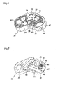
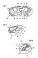
- Figures 6 to 11 show an intervertebral implant or interbody fusion cage according to a third embodiment of the invention.
- the body 30 consists of two parts 31, 32 hinged horizontally to one another between a first relative position, called open position, where the parts 31, 32 are aligned (FIG. a second relative position, said closed position, where the portions 31, 32 are at an angle to each other ( Figure 6) and give the cage a conventional arcuate shape.
- the articulation between the parts 31, 32 is made by cooperating with a male articulation member 33, of cylindrical shape, of the part 32 with a female articulation member or cavity 34, of correspondingly cylindrical shape, of the part 31
- the male member 33 comprises a horizontal rib 35 along its periphery, which rib cooperates with a corresponding horizontal groove 36 formed in the wall of the cavity 34 for vertically positioning and locking the body portions 31, 32, one by report to the other.
- the rib could be located on the wall of the cavity 34 and the corresponding groove in the male member 33.
- the cavity 34 defines laterally two guiding and abutment members 37, 38 which cooperate with corresponding cavities 39, 40 of the part 32 located on either side of the male articulation member 33 to guide and limit the stroke relative parts 31, 32.
- the guiding and abutment member 37, respectively 38, abuts against the bottom of the cavity 39, respectively 40, when the portions 31, 32 are in their open relative position, respectively closed.
- This vertical rib 41 slides on the guide and abutment member 38 while maintaining the side walls of the cavity 40 spaced elastically when the portions 31, 32 move between their open relative position and their closed relative position.
- the rib 41 is housed in a corresponding vertical latching groove 42 formed in the guiding and abutment member 38 when the latter comes into abutment in the bottom of the cavity 40, that is to say when the parts 31, 32 reach their closed relative position. In this position, the cavity 40 returns to its rest form, undeformed, and the body portions 31, 32 are locked.
- the vertical rib 41 could be located on the guide and abutment member 38 and the corresponding groove 42 in the wall of the cavity 40.
- the closed relative position of the body portions 31, 32 is particularly adapted to the introduction of the cage into the space of the intervertebral disc. Indeed, as already indicated, the passage or posterior path practiced through the tissue by which the cage is introduced is narrow. As an illustration, this passage has been shown schematically in Figure 12 by dashed lines designated by the reference VP, the space of the intervertebral disk being designated by the ED mark.
- the conventional arched shape of an interbody fusion cage does not facilitate the introduction and movement of the cage in this VP passage.
- the articulated cage according to this third embodiment of the invention is introduced and moved longitudinally in this passage VP then that the body portions 31, 32 are in their open relative position, where the cage is rectilinear ( Figure 8).
- the body portions 31, 32 comprise in their thickness respectively a blind longitudinal hole 43 and a longitudinal through hole 44 which are aligned when the body portions 31, 32 are in their open relative position.
- These holes 43, 44 are intended to receive a rod 45 of a first gripping instrument (FIG. 11), which keeps the body portions 31, 32 in their open relative position. This instrument is gradually removed as soon as the cage has entered the space of the intervertebral disk ED.
- the cage according to this third embodiment comprises coupling means 46 to 51 identical to the means 12 to 17 of the first embodiment.
- These coupling means 46 to 51 receive a second gripping instrument, designated in FIG. 11 by reference numeral 52, which, thanks to its freedom in rotation relative to the cage, makes it possible to rotate the cage as a whole for the placing in the anterior portion of the space of the intervertebral disk ED and rotating the body portions 31, 32 relative to each other until the locking of these portions 31, 32 in their closed relative position.
- this second instrument 52 is coupled to the cage before its introduction into the passageway VP. It is unscrewed from the cage and removed as soon as the cage has been put into its final position.
- the intersomatic fusion cage according to this third embodiment may also comprise a pivot 50 and a corresponding cutting protuberance (not shown) on one or each of the upper and lower faces of the body 30, as in the first embodiment, for facilitate the rotation then the positioning of the cage.
Abstract
Description
La présente invention concerne un implant intervertébral, destiné à maintenir un espace souhaité entre deux corps vertébraux d'une colonne vertébrale. Un tel implant est également connu sous le nom de « cage de fusion intersomatique ». Il sert à traiter les pathologies du disque intervertébral.The present invention relates to an intervertebral implant for maintaining a desired space between two vertebral bodies of a spine. Such an implant is also known as an "interbody fusion cage". It is used to treat pathologies of the intervertebral disc.
Une cage de fusion intersomatique est généralement placée à l'intérieur d'un disque intervertébral dont on a réalisé préalablement une discectomie partielle. La cage de fusion intersomatique rétablit la hauteur du disque intervertébral et permet aux corps vertébraux de fusionner. Des exemples de cages de fusion intersomatique sont décrits dans les demandes de brevet internationales
Il existe plusieurs techniques de mise en place d'une cage de fusion intersomatique. La technique à laquelle s'intéresse tout particulièrement l'invention est la technique « TLIF » (Transforaminal Lumbar Interbody Fusion) selon laquelle la cage est introduite par une voie postérieure unilatérale ouverte à travers les tissus.There are several techniques for setting up an interbody fusion cage. The technique to which the invention is particularly interested is the "TLIF" technique (Transforaminal Lumbar Interbody Fusion) according to which the cage is introduced by a unilateral posterior path open through the tissues.
Une cage de fusion intersomatique doit être placée dans une position bien déterminée dans l'espace du disque intervertébral. La cage est plus précisément placée dans la partie antérieure dudit espace. Les cages de fusion intersomatique que l'on utilise dans le cadre de la technique TLIF ont généralement une forme arquée, avec une face convexe et une face concave. La face convexe doit être mise en regard du côté antérieur de l'espace du disque intervertébral et la face concave en regard du côté postérieur. Pour ce faire, il est nécessaire de faire tourner la cage après son introduction dans l'espace du disque intervertébral. Cette mise en place de la cage est assez délicate à réaliser et nécessite l'emploi d'un nombre relativement élevé d'instruments coudés.An interbody fusion cage must be placed in a well-defined position in the space of the intervertebral disc. The cage is more precisely placed in the front part of said space. The intersomatic fusion cages used in the TLIF technique generally have an arcuate shape, with a convex face and a concave face. The convex side must be compared with the anterior side of the space of the intervertebral disc and the concave side facing the posterior side. To do this, it is necessary to rotate the cage after its introduction into the space of the intervertebral disc. This establishment of the cage is quite delicate to achieve and requires the use of a relatively large number of bent instruments.
La demande de brevet
En autorisant une rotation entre la cage et son instrument de préhension, le nombre d'instruments nécessaires à la mise en place de la cage est réduit. Toutefois, malgré cette liberté en rotation, faire tourner la cage pour la mettre dans sa position finale reste une opération délicate. De plus, le mode de liaison entre la cage et l'instrument de préhension présente plusieurs inconvénients. Du fait de la section oblongue des évidements verticaux, un jeu en translation horizontale existera entre l'ergot d'accrochage et les évidements verticaux si le tube de blocage n'est pas suffisamment serré contre la paroi de la cage. Un tel jeu nuira à la précision de déplacement de la cage. Un autre inconvénient est que ce mode de liaison impose au chirurgien d'effectuer des serrages et desserrages successifs et fastidieux du tube de blocage pendant la mise en place de la cage.By allowing a rotation between the cage and its gripping instrument, the number of instruments necessary for the establishment of the cage is reduced. However, despite this freedom in rotation, turning the cage to put it in its final position remains a delicate operation. In addition, the mode of connection between the cage and the gripping instrument has several disadvantages. Due to the oblong section of the vertical recesses, a horizontal translational clearance will exist between the hooking lug and the vertical recesses if the locking tube is not sufficiently tight against the wall of the cage. Such a game will interfere with the accuracy of movement of the cage. Another disadvantage is that this method of binding requires the surgeon to perform successive and tedious tightening and loosening of the locking tube during the establishment of the cage.
La présente invention vise à proposer un implant intervertébral conçu pour faciliter sa rotation dans sa position finale lors de sa mise en place entre deux corps vertébraux.The present invention aims to provide an intervertebral implant designed to facilitate its rotation in its final position when placed between two vertebral bodies.
A cette fin, il est prévu un implant intervertébral comprenant un corps comprenant des faces supérieure et inférieure destinées à être en contact avec des corps vertébraux respectifs pour maintenir un espace souhaité entre ces corps vertébraux, caractérisé en ce qu'il comprend un pivot sur l'une au moins des faces supérieure et inférieure. Un tel pivot peut coopérer avec le corps vertébral correspondant pendant la mise en place de l'implant pour permettre une rotation aisée de celui-ci autour de l'axe imaginaire défini par le pivot.To this end, there is provided an intervertebral implant comprising a body comprising upper and lower faces intended to be in contact with respective vertebral bodies to maintain a desired space between these vertebral bodies, characterized in that it comprises a pivot on the at least one upper and lower faces. Such pivot may cooperate with the corresponding vertebral body during the introduction of the implant to allow easy rotation thereof around the imaginary axis defined by the pivot.
Pour faciliter encore sa mise en place, l'implant intervertébral selon l'invention comprend en outre, de préférence, des moyens d'accouplement à un instrument de préhension agencés pour autoriser une rotation de l'instrument par rapport à l'implant, ces moyens d'accouplement comprenant un logement ménagé dans le corps et débouchant sur une face périphérique dudit corps et un organe mobile en rotation dans le logement, cet organe mobile étant apte à s'accoupler avec une extrémité de l'instrument. De tels moyens d'accouplement permettent l'utilisation d'un instrument de préhension sans tube de blocage et simple à manipuler.To further facilitate its implementation, the intervertebral implant according to the invention also preferably comprises means for coupling to a grasping instrument arranged to allow rotation of the instrument relative to the implant, these coupling means comprising a housing formed in the body and opening on a peripheral face of said body and a member movable in rotation in the housing, said movable member being adapted to mate with one end of the instrument. Such coupling means allow the use of a gripping instrument without locking tube and easy to handle.
De préférence, afin de faciliter encore la mise en place de l'implant selon l'invention, le corps comprend des première et seconde parties articulées horizontalement entre une première position relative où les première et seconde parties sont sensiblement alignées et une seconde position relative où les première et seconde parties font un angle entre elles. La première position relative confère à l'implant une forme temporaire droite qui lui permet de se déplacer plus aisément dans le passage ou voie postérieur, généralement étroit, qui est pratiqué dans les tissus. La seconde position relative est la position finale, qui donne à l'implant une forme arquée adaptée à sa fonction.Preferably, in order to further facilitate the placement of the implant according to the invention, the body comprises first and second parts articulated horizontally between a first relative position where the first and second parts are substantially aligned and a second relative position where the first and second parts are at an angle to each other. The first relative position gives the implant a straight temporary shape that allows it to move more easily in the generally narrow passageway or posterior pathway that is practiced in the tissues. The second relative position is the end position, which gives the implant an arched shape adapted to its function.
Des modes de réalisation particuliers de l'invention sont définis dans les revendications dépendantes annexées.Particular embodiments of the invention are defined in the appended dependent claims.
D'autres caractéristiques et avantages de la présente invention apparaîtront à la lecture de la description détaillée suivante faite en référence aux dessins annexés dans lesquels :
- les figures 1 à 3 sont respectivement une vue en perspective de dessus, une vue de côté et une coupe horizontale en perspective, prise suivant le plan III-III de la figure 2, d'un implant intervertébral selon un premier mode de réalisation de l'invention ;
- les figures 4 et 5 sont respectivement une vue en perspective de dessus et une vue de côté d'un implant intervertébral selon un second mode de réalisation de l'invention ;
- les figures 6 à 8 sont respectivement une vue en perspective de dessus, une coupe horizontale en perspective et une vue plane de dessus d'un implant intervertébral selon un troisième mode de réalisation de l'invention ;
- les figures 9 et 10 sont respectivement des vues en perspective de deux parties formant le corps de l'implant intervertébral selon le troisième mode de réalisation de l'invention ;
- la figure 11 est une vue plane en coupe horizontale de l'implant intervertébral selon le troisième mode de réalisation de l'invention accouplé à deux instruments de préhension et de manipulation ;
- la figure 12 montre l'implant intervertébral selon le troisième mode de réalisation de l'invention dans sa position finale sur une vertèbre.
- Figures 1 to 3 are respectively a perspective view from above, a side view and a horizontal section in perspective, taken next the plane III-III of Figure 2, an intervertebral implant according to a first embodiment of the invention;
- Figures 4 and 5 are respectively a perspective view from above and a side view of an intervertebral implant according to a second embodiment of the invention;
- Figures 6 to 8 are respectively a perspective view from above, a horizontal section in perspective and a plan view from above of an intervertebral implant according to a third embodiment of the invention;
- Figures 9 and 10 are respectively perspective views of two parts forming the body of the intervertebral implant according to the third embodiment of the invention;
- Figure 11 is a horizontal sectional plan view of the intervertebral implant according to the third embodiment of the invention coupled to two instruments for gripping and manipulation;
- Figure 12 shows the intervertebral implant according to the third embodiment of the invention in its final position on a vertebra.
En référence aux figures 1 à 3, un implant intervertébral ou cage de fusion intersomatique selon un premier mode de réalisation de l'invention comprend un corps de forme arquée 1 comprenant une face supérieure 2, une face inférieure 3, une face antérieure convexe 4, une face postérieure concave 5 et deux faces d'extrémité arrondies 6, 7 reliant les faces antérieure 4 et postérieure 5. Les faces antérieure 4, postérieure 5 et d'extrémité 6, 7 définissent ensemble la périphérie du corps 1.With reference to FIGS. 1 to 3, an intervertebral implant or interbody fusion cage according to a first embodiment of the invention comprises an
Les faces supérieure et inférieure 2, 3 sont destinées à être en contact avec deux corps vertébraux adjacents respectifs, plus précisément avec deux plateaux vertébraux. Des picots 8 sont prévus sur ces faces supérieure et inférieure 2, 3 pour s'ancrer dans les plateaux vertébraux.The upper and
Des orifices 9 traversant le corps 1 sur toute sa hauteur permettent la fusion des corps vertébraux. Des trous de vascularisation (non représentés) peuvent également être prévus.
Conformément à l'invention, le corps 1 comporte sur chacune des faces supérieure et inférieure 2, 3, ou au moins sur l'une d'entre elles, un pivot 10, 11. Les pivots 10, 11 sont situés à une extrémité du corps 1 et sont alignés l'un par rapport à l'autre. Dans l'exemple représenté, les pivots 10, 11 ont une forme hémisphérique. Ils pourraient néanmoins avoir une autre forme, par exemple conique ou pyramidale.According to the invention, the
La cage peut être mise en place selon la technique TLIF. Une voie d'abord unilatérale postérieure est ouverte à droite ou à gauche de la colonne vertébrale, les corps vertébraux entre lesquels doit être introduite la cage sont distractés, les parties du disque intervertébral affectées sont retirées et la cage est introduite par ladite voie. La distraction des corps vertébraux doit être suffisante pour que les pivots 10, 11 ne puissent pas gêner l'introduction de la cage. Une fois la cage introduite dans l'espace du disque intervertébral, la distraction des corps vertébraux est relâchée, Les plateaux vertébraux viennent alors au contact des pivots 10, 11, qui forment une dépression dans les plateaux vertébraux. La cage peut ensuite être tournée aisément jusque dans sa position finale autour d'un axe imaginaire unique passant par les pivots 10, 11. Un impactage des corps vertébraux sur la cage permet aux plateaux vertébraux de venir au contact des faces supérieure et inférieure 2, 3 et aux picots 8 de s'ancrer dans les plateaux vertébraux pour fixer la cage en position.The cage can be put in place according to the TLIF technique. A unilateral posterior approach is open to the right or left of the spine, the vertebral bodies between which the cage must be introduced are distracted, the parts of the intervertebral disc affected are removed and the cage is introduced by said path. The distraction of the vertebral bodies must be sufficient so that the
Selon une autre caractéristique de l'invention, le corps 1 comprend à son extrémité opposée à celle comprenant les pivots 10, 11 un logement 12 débouchant sur sa périphérie, plus précisément sur la face d'extrémité 7. Dans l'exemple illustré, le logement 12 est sphérique et débouche sur la face d'extrémité 7 par l'intermédiaire d'une ouverture tronconique 13 évasée vers l'extérieur. Un organe d'accouplement de forme sphérique 14 est disposé dans le logement 12 de manière à pouvoir se déplacer en rotation sur lui-même, sans jeu, à la manière d'une rotule, tout en restant prisonnier du logement 12. Cet organe d'accouplement 14 est traversé le long d'un de ses axes par un alésage taraudé 15 dont le diamètre est plus petit que le petit diamètre de l'ouverture tronconique 13 et qui communique avec l'ouverture tronconique 13 pour pouvoir recevoir à travers cette ouverture 13 une extrémité filetée d'une tige d'un instrument de préhension (non représenté).According to another characteristic of the invention, the
L'organe d'accouplement mobile 14 confère ainsi à la cage une liberté en rotation par rapport à son instrument de préhension dans des limites définies par la paroi de l'ouverture tronconique 13, paroi qui sert de surface d'appui et de butée pour l'instrument de préhension. Cette liberté en rotation s'exerce dans toutes les directions à l'intérieur du cône défini par la paroi de l'ouverture 13, et donc en particulier dans des plans horizontaux et verticaux. Un tel instrument de préhension pourra donc servir à la fois à faire entrer la cage dans l'espace du disque intervertébral et à faire tourner cette cage horizontalement pour lui donner sa position finale. La liberté en rotation verticale de la cage par rapport à l'instrument facilitera quant à elle l'introduction et le déplacement de la cage dans le passage la conduisant dans l'espace du disque intervertébral, passage qui est étroit et qui offre peu de visibilité au chirurgien. En variante, néanmoins, on peut donner à l'organe d'accouplement mobile 14 une forme cylindrique, plutôt que sphérique, si une telle liberté en rotation verticale n'est pas souhaitée.The
Lorsque, comme dans l'exemple illustré, l'organe d'accouplement 14 a une forme sphérique, un ergot 16 situé sur l'organe d'accouplement 14 coopère avec un logement 17 de plus grande taille pratiqué dans le corps 1 pour bloquer en rotation l'organe d'accouplement 14 dans les sens du vissage et du dévissage de l'extrémité filetée de l'instrument dans l'alésage 15 et permettre ainsi l'accouplement et le désaccouplement de la cage et de l'instrument.When, as in the example illustrated, the
Les figures 4 et 5 montrent un implant intervertébral ou cage de fusion intersomatique selon un second mode de réalisation de l'invention. Dans ce second mode de réalisation, la cage comporte sur chacune ou l'une au moins de ses faces supérieure et inférieure 20, 21, en plus du pivot 22, 23, ici de forme conique, et des picots d'ancrage 24, une protubérance 25, 26 de hauteur inférieure à celle du pivot 22, 23 mais très supérieure à celle des picots d'ancrage 24. Les protubérances 25, 26 ont une face plane inclinée 27 qui définit, avec une face périphérique des protubérances 25, 26, une arête coupante 28. Cette arrête 28 a, dans le plan de la face 27, une forme courbe, de préférence elliptique comme représenté, permettant aux protubérances 25, 26 de venir s'ancrer progressivement dans les plateaux vertébraux pendant la manoeuvre de rotation de la cage autour de l'axe imaginaire passant par les pivots 22, 23 et le raprochement des vertèbres consécutif au relâchement de la distraction. Cet ancrage des protubérances 25, 26 permet de fixer la position finale de la cage avant l'impactage.Figures 4 and 5 show an intervertebral implant or interbody fusion cage according to a second embodiment of the invention. In this second embodiment, the cage comprises on each or at least one of its upper and lower faces 20, 21, in addition to the
Les figures 6 à 11 montrent un implant intervertébral ou cage de fusion intersomatique selon un troisième mode de réalisation de l'invention. Dans ce troisième mode de réalisation, le corps 30 est constitué de deux parties 31, 32 articulées horizontalement l'une à l'autre entre une première position relative, dite position ouverte, où les parties 31, 32 sont alignées (figure 8) et une seconde position relative, dite position fermée, où les parties 31, 32 font un angle entre elles (figure 6) et confèrent à la cage une forme conventionnelle arquée.Figures 6 to 11 show an intervertebral implant or interbody fusion cage according to a third embodiment of the invention. In this third embodiment, the
L'articulation entre les parties 31, 32 est réalisée en faisant coopérer un organe d'articulation mâle 33, de forme cylindrique, de la partie 32 avec un organe d'articulation femelle ou cavité 34, de forme correspondante cylindrique, de la partie 31. L'organe mâle 33 comprend une nervure horizontale 35 le long de sa périphérie, nervure qui coopère avec une gorge horizontale correspondante 36 pratiquée dans la paroi de la cavité 34 pour positionner et bloquer verticalement les parties de corps 31, 32 l'une par rapport à l'autre. En variante, bien entendu, la nervure pourrait être située sur la paroi de la cavité 34 et la gorge correspondante dans l'organe mâle 33.The articulation between the
La cavité 34 définit latéralement deux organes de guidage et de butée 37, 38 qui coopèrent avec des cavités correspondantes 39, 40 de la partie 32 situées de part et d'autre de l'organe d'articulation mâle 33 pour guider et limiter la course relative des parties 31, 32. L'organe de guidage et de butée 37, respectivement 38, est en butée contre le fond de la cavité 39, respectivement 40, lorsque les parties 31, 32 sont dans leur position relative ouverte, respectivement fermée.The
Celle des cavités 39, 40 la plus proche du côté postérieur de la cage, à savoir la cavité 40, comporte sur sa paroi latérale opposée à l'organe mate 33 une nervure verticale d'encliquetage 41 (cf. figure 8). Cette nervure verticale 41 glisse sur l'organe de guidage et de butée 38 en maintenant les parois latérales de la cavité 40 écartées élastiquement lorsque les parties 31, 32 se déplacent entre leur position relative ouverte et leur position relative fermée. La nervure 41 vient se loger dans une rainure verticale d'encliquetage correspondante 42 pratiquée dans l'organe de guidage et de butée 38 lorsque ce dernier arrive en butée dans le fond de la cavité 40, c'est-à-dire lorsque les parties 31, 32 atteignent leur position relative fermée. Dans cette position, la cavité 40 retrouve sa forme de repos, non déformée, et les parties de corps 31, 32 sont verrouillées. En variante, bien entendu, la nervure verticale 41 pourrait être située sur l'organe de guidage et de butée 38 et la rainure correspondante 42 dans la paroi de la cavité 40.That of the
La position relative fermée des parties de corps 31, 32 est particulièrement adaptée à l'introduction de la cage dans l'espace du disque intervertébral. En effet, comme déjà indiqué, le passage ou voie postérieur pratiqué à travers les tissus par lequel la cage est introduite est étroit. A titre d'illustration, ce passage a été représenté de manière schématique à la figure 12 par des traits pointillés désignés par le repère VP, l'espace du disque intervertébral étant lui désigné par le repère ED. La forme conventionnelle arquée d'une cage de fusion intersomatique ne facilite pas l'introduction et le déplacement de la cage dans ce passage VP. La cage articulée selon ce troisième mode de réalisation de l'invention est introduite et déplacée longitudinalement dans ce passage VP alors que les parties de corps 31, 32 sont dans leur position relative ouverte, où la cage est rectiligne (figure 8). A cet effet, les parties de corps 31, 32 comprennent dans leur épaisseur respectivement un trou longitudinal borgne 43 et un trou longitudinal traversant 44 qui sont alignés lorsque les parties de corps 31, 32 sont dans leur position relative ouverte. Ces trous 43, 44 sont destinés à recevoir une tige 45 d'un premier instrument de préhension (figure 11), qui maintient les parties de corps 31, 32 dans leur position relative ouverte. Cet instrument est retiré progressivement dès que la cage a pénétré dans l'espace du disque intervertébral ED.The closed relative position of the
La position relative ouverte des parties de corps 31, 32 correspond, quant à elle, à la position d'implantation finale de la cage, comme montré à la figure 12. Pour pouvoir manipuler la cage et la mettre dans sa position finale après qu'elle a pénétré dans l'espace du disque intervertébral ED, la cage selon ce troisième mode de réalisation comprend des moyens d'accouplement 46 à 51 identiques aux moyens 12 à 17 du premier mode de réalisation. Ces moyens d'accouplement 46 à 51 reçoivent un second instrument de préhension, désigné à la figure 11 par le repère 52, qui, grâce à sa liberté en rotation par rapport à la cage, permet de faire tourner la cage dans son ensemble pour la placer dans la partie antérieure de l'espace du disque intervertébral ED et de faire tourner les parties de corps 31, 32 l'une par rapport à l'autre jusqu'au verrouillage de ces parties 31, 32 dans leur position relative fermée. Comme le premier instrument 45, ce second instrument 52 est accouplé à la cage avant son introduction dans le passage VP. Il est devissé de la cage et retiré dès que la cage a été mise dans sa position finale.The relative open position of the
La cage de fusion intersomatique selon ce troisième mode de réalisation peut aussi comprendre un pivot 50 et une protubérance coupante correspondante (non représentée) sur l'une ou chacune des faces supérieure et inférieure du corps 30, comme dans le premier mode de réalisation, pour faciliter la rotation puis le positionnement de la cage.The intersomatic fusion cage according to this third embodiment may also comprise a
Claims (19)
caractérisé en ce que l'une des première et seconde parties (31, 32) du corps (30), dite partie mâle (32), comprend un organe d'articulation mâle (33) coopérant avec un organe d'articulation femelle (34) de l'autre partie du corps (30), dite partie femelle (31), pour l'articulation des première et seconde parties (31, 32), et en ce que l'organe d'articulation femelle (34) définit des premier et second organes de guidage et de butée (37, 38) qui coopèrent avec des première et seconde cavités (39, 40) de la partie mâle (32) lorsque lesdites parties mâle et femelle (31, 32) sont dans leurs première et seconde positions relatives, respectivement.Intervertebral implant according to one of claims 12 to 14,
characterized in that one of the first and second portions (31,32) of the body (30), said male portion (32), comprises a male hinge member (33) cooperating with a female hinge member (34). ) of the other part of the body (30), said female part (31), for the articulation of the first and second parts (31, 32), and in that the female articulation member (34) defines first and second guide and stop members (37, 38) which cooperate with first and second cavities (39, 40) of the male portion (32) when said male and female portions (31, 32) are in their first and second second relative positions, respectively.
caractérisé en ce que sa forme et sa taille sont adaptées à une introduction entre deux corps vertébraux par voie postérieure unilatérale.Intervertebral implant according to any one of claims 1 to 18,
characterized in that its shape and size are adapted for introduction between two vertebral bodies unilaterally posteriorly.
Priority Applications (3)
| Application Number | Priority Date | Filing Date | Title |
|---|---|---|---|
| AT06024186T ATE439817T1 (en) | 2006-11-22 | 2006-11-22 | INTERVERBARY IMPLANT |
| DE602006008636T DE602006008636D1 (en) | 2006-11-22 | 2006-11-22 | Intervertebral implant |
| EP06024186A EP1925271B1 (en) | 2006-11-22 | 2006-11-22 | Intervertebral implant |
Applications Claiming Priority (1)
| Application Number | Priority Date | Filing Date | Title |
|---|---|---|---|
| EP06024186A EP1925271B1 (en) | 2006-11-22 | 2006-11-22 | Intervertebral implant |
Publications (2)
| Publication Number | Publication Date |
|---|---|
| EP1925271A1 true EP1925271A1 (en) | 2008-05-28 |
| EP1925271B1 EP1925271B1 (en) | 2009-08-19 |
Family
ID=37946392
Family Applications (1)
| Application Number | Title | Priority Date | Filing Date |
|---|---|---|---|
| EP06024186A Not-in-force EP1925271B1 (en) | 2006-11-22 | 2006-11-22 | Intervertebral implant |
Country Status (3)
| Country | Link |
|---|---|
| EP (1) | EP1925271B1 (en) |
| AT (1) | ATE439817T1 (en) |
| DE (1) | DE602006008636D1 (en) |
Cited By (11)
| Publication number | Priority date | Publication date | Assignee | Title |
|---|---|---|---|---|
| FR2948277A1 (en) * | 2009-07-27 | 2011-01-28 | Medicrea International | ASSEMBLY COMPRISING AN INTERVERTEBRAL IMPLANT FOR IMMOBILIZING A VERTEBRA IN RELATION TO ANOTHER AND A POSITION INSTRUMENT OF THIS IMPLANT |
| EP2303196A1 (en) * | 2008-07-23 | 2011-04-06 | Marc I. Malberg | Modular nucleus pulposus prosthesis |
| FR2952526A1 (en) * | 2009-11-17 | 2011-05-20 | Orthopaedic & Spine Dev | Variable angular geometry prosthesis for spacing upper and lower vertebral bodies in surgical field, has ends assuring rotational stop of body using covers, where rotational stop is consolidated via end of element projected on arm |
| WO2011108950A1 (en) * | 2010-03-03 | 2011-09-09 | Lfc Spółka Z.O.O. | Prosthesis for spinal column, instrument for its guiding and method for implantation thereof |
| EP2364114A1 (en) * | 2008-10-13 | 2011-09-14 | Globus Medical, Inc. | Intervertebral spacer |
| WO2012083173A3 (en) * | 2010-12-17 | 2012-12-27 | Kyphon Sarl | Flexible spinal implant |
| US9364338B2 (en) | 2008-07-23 | 2016-06-14 | Resspond Spinal Systems | Modular nucleus pulposus prosthesis |
| CN106037998A (en) * | 2016-07-05 | 2016-10-26 | 杨晋才 | Variable-angle interbody fusion device |
| CN110368146A (en) * | 2019-07-12 | 2019-10-25 | 浙江科惠医疗器械股份有限公司 | A kind of rotary opening formula Invasive lumbar fusion device |
| CN112932749A (en) * | 2021-01-28 | 2021-06-11 | 燕山大学 | Combined type porous interbody fusion cage and processing method thereof |
| EP3865096A1 (en) * | 2020-02-05 | 2021-08-18 | K2M, Inc. | Flexible interbody implant |
Families Citing this family (5)
| Publication number | Priority date | Publication date | Assignee | Title |
|---|---|---|---|---|
| US8021429B2 (en) | 2007-03-08 | 2011-09-20 | Zimmer Spine, Inc. | Deployable segmented TLIF device |
| US8545566B2 (en) | 2008-10-13 | 2013-10-01 | Globus Medical, Inc. | Articulating spacer |
| CA2793185C (en) | 2010-03-16 | 2019-02-12 | Pinnacle Spine Group, Llc | Intervertebral implants and graft delivery systems and methods |
| US9380932B1 (en) | 2011-11-02 | 2016-07-05 | Pinnacle Spine Group, Llc | Retractor devices for minimally invasive access to the spine |
| WO2014159739A1 (en) | 2013-03-14 | 2014-10-02 | Pinnacle Spine Group, Llc | Interbody implants and graft delivery systems |
Citations (5)
| Publication number | Priority date | Publication date | Assignee | Title |
|---|---|---|---|---|
| DE19710392C1 (en) | 1997-03-13 | 1999-07-01 | Haehnel Michael | Slipped disc implant comprises an extensible, hinged or wound body |
| WO2005087143A1 (en) | 2004-03-10 | 2005-09-22 | Sepitec Foundation | Implant used in stabilising operations on the thoracic and lumbar vertebral column |
| WO2006066228A2 (en) * | 2004-12-16 | 2006-06-22 | Innovative Spinal Technologies | Expandable implants for spinal disc replacement |
| WO2006079356A1 (en) | 2005-01-28 | 2006-08-03 | Advanced Medical Technologies Ag | Implant for transforaminal intracorporeal fusion |
| US20060241761A1 (en) * | 2005-04-08 | 2006-10-26 | G&L Consulting | Spine implant insertion device and method |
-
2006
- 2006-11-22 DE DE602006008636T patent/DE602006008636D1/en active Active
- 2006-11-22 AT AT06024186T patent/ATE439817T1/en not_active IP Right Cessation
- 2006-11-22 EP EP06024186A patent/EP1925271B1/en not_active Not-in-force
Patent Citations (5)
| Publication number | Priority date | Publication date | Assignee | Title |
|---|---|---|---|---|
| DE19710392C1 (en) | 1997-03-13 | 1999-07-01 | Haehnel Michael | Slipped disc implant comprises an extensible, hinged or wound body |
| WO2005087143A1 (en) | 2004-03-10 | 2005-09-22 | Sepitec Foundation | Implant used in stabilising operations on the thoracic and lumbar vertebral column |
| WO2006066228A2 (en) * | 2004-12-16 | 2006-06-22 | Innovative Spinal Technologies | Expandable implants for spinal disc replacement |
| WO2006079356A1 (en) | 2005-01-28 | 2006-08-03 | Advanced Medical Technologies Ag | Implant for transforaminal intracorporeal fusion |
| US20060241761A1 (en) * | 2005-04-08 | 2006-10-26 | G&L Consulting | Spine implant insertion device and method |
Cited By (22)
| Publication number | Priority date | Publication date | Assignee | Title |
|---|---|---|---|---|
| EP2303196A4 (en) * | 2008-07-23 | 2012-07-04 | Marc I Malberg | Modular nucleus pulposus prosthesis |
| EP2303196A1 (en) * | 2008-07-23 | 2011-04-06 | Marc I. Malberg | Modular nucleus pulposus prosthesis |
| US9364338B2 (en) | 2008-07-23 | 2016-06-14 | Resspond Spinal Systems | Modular nucleus pulposus prosthesis |
| US8795375B2 (en) | 2008-07-23 | 2014-08-05 | Resspond Spinal Systems | Modular nucleus pulposus prosthesis |
| EP2364114A1 (en) * | 2008-10-13 | 2011-09-14 | Globus Medical, Inc. | Intervertebral spacer |
| EP2364114A4 (en) * | 2008-10-13 | 2013-05-29 | Globus Medical Inc | Intervertebral spacer |
| US9101492B2 (en) | 2009-07-27 | 2015-08-11 | Medicrea International | Set comprising an intervertebral implant for immobilising a vertebra with respect to another and an instrument for installing this implant |
| FR2948277A1 (en) * | 2009-07-27 | 2011-01-28 | Medicrea International | ASSEMBLY COMPRISING AN INTERVERTEBRAL IMPLANT FOR IMMOBILIZING A VERTEBRA IN RELATION TO ANOTHER AND A POSITION INSTRUMENT OF THIS IMPLANT |
| WO2011013047A3 (en) * | 2009-07-27 | 2011-04-07 | Medicrea International | Set comprising an intervertebral implant for immobilising a vertebra with respect to another and an instrument for installing this implant |
| FR2952526A1 (en) * | 2009-11-17 | 2011-05-20 | Orthopaedic & Spine Dev | Variable angular geometry prosthesis for spacing upper and lower vertebral bodies in surgical field, has ends assuring rotational stop of body using covers, where rotational stop is consolidated via end of element projected on arm |
| RU2570967C2 (en) * | 2010-03-03 | 2015-12-20 | Лфс Сполка З.О.О. | Anterior spinal implant, implant guide instrument and method for installing it |
| US8753400B2 (en) | 2010-03-03 | 2014-06-17 | LfC Sp. z o.o. | Prosthesis of anterior spinal column, instrument guiding the prosthesis and method for installation thereof |
| WO2011108950A1 (en) * | 2010-03-03 | 2011-09-09 | Lfc Spółka Z.O.O. | Prosthesis for spinal column, instrument for its guiding and method for implantation thereof |
| CN102869322A (en) * | 2010-03-03 | 2013-01-09 | Lfc斯博拉卡公司 | Prosthesis for spinal column, instrument for its guiding and method for implantation thereof |
| WO2012083173A3 (en) * | 2010-12-17 | 2012-12-27 | Kyphon Sarl | Flexible spinal implant |
| US8512408B2 (en) | 2010-12-17 | 2013-08-20 | Warsaw Orthopedic, Inc. | Flexiable spinal implant |
| CN106037998A (en) * | 2016-07-05 | 2016-10-26 | 杨晋才 | Variable-angle interbody fusion device |
| CN110368146A (en) * | 2019-07-12 | 2019-10-25 | 浙江科惠医疗器械股份有限公司 | A kind of rotary opening formula Invasive lumbar fusion device |
| CN110368146B (en) * | 2019-07-12 | 2020-07-31 | 浙江科惠医疗器械股份有限公司 | Rotary expanding type interbody fusion cage |
| EP3865096A1 (en) * | 2020-02-05 | 2021-08-18 | K2M, Inc. | Flexible interbody implant |
| US11707361B2 (en) | 2020-02-05 | 2023-07-25 | K2M, Inc. | Flexible interbody implant |
| CN112932749A (en) * | 2021-01-28 | 2021-06-11 | 燕山大学 | Combined type porous interbody fusion cage and processing method thereof |
Also Published As
| Publication number | Publication date |
|---|---|
| DE602006008636D1 (en) | 2009-10-01 |
| EP1925271B1 (en) | 2009-08-19 |
| ATE439817T1 (en) | 2009-09-15 |
Similar Documents
| Publication | Publication Date | Title |
|---|---|---|
| EP1925271B1 (en) | Intervertebral implant | |
| EP1299054B1 (en) | Intersomatic implant | |
| EP1089677B1 (en) | Backbone intersomatic implant with anchoring elements | |
| FR2771282A1 (en) | Surgical support implant for spine | |
| FR2893838A1 (en) | Intervertebral disc prosthesis for insertion in spinal column, has osseous anchoring element positioned near peripheral edge of preset plate among pair of plates such that curved articulation surface is formed on preset plate | |
| EP2231074B1 (en) | Intervertebral stabilization assembly for arthrodesis, comprising an impaction cage body, and an ancillary device for implanting same | |
| EP2308426A1 (en) | Intersomatic implants in two parts | |
| WO2007065993A2 (en) | Cases for setting and intersomatically fusing vertebrae | |
| FR2865630A1 (en) | Intervertebral disk prosthesis insertion device, has clamp comprising rear surface with form for engaging with form of rear edge of prosthesis that is held by flexible blades mounted on lateral edges of clamp | |
| FR2914180A1 (en) | EXPANSIVE CAGE FOR VERTEBRAL SURGERY. | |
| FR2715293A1 (en) | Vertebral interbody fusion cage. | |
| FR2763836A1 (en) | CERVICAL INTERVERTEBRAL CAGE | |
| FR2977474A1 (en) | INTERSOMATIC CAGE, IN PARTICULAR OF THE TRANSFORAMINAL TYPE | |
| WO2010142882A1 (en) | Intervertebral implant and tool for placing same | |
| EP3554428B1 (en) | Ancillary device for implanting a cup for a cotyloid implant of a total hip prosthesis | |
| FR2764795A1 (en) | Inervertebral spinal fixation cage | |
| WO2013117861A1 (en) | Intersomatic implant and tool for installing such an implant | |
| FR2796268A1 (en) | DEVICE FOR HOLDING A FRAMEWORK FOR RECEIVING A HOLDING AND FILLING PRODUCT WITHOUT THE RISK OF SPREADING THE SAME INSIDE THE HUMAN BODY | |
| WO2018127574A1 (en) | Intervertebral implant with graft retention | |
| WO2014140503A1 (en) | Spinal ancillary device | |
| EP2389903B1 (en) | System for performing arthrodesis between two vertebrae and installation accessories | |
| WO2014140445A1 (en) | Intervertebral fusion implant and surgical instrument for fitting this implant in place | |
| WO2016146898A1 (en) | Interbody cage, particularly of the transforaminal type | |
| FR2929504A1 (en) | Prosthesis assembly for accompanying intervertebral movement, has nose rotated to simultaneously induce opening of intervertebral space and displacement of cage body similar to that of cam, when nose is introduced into intervertebral space | |
| FR2893839A1 (en) | Intervertebral disc prosthesis inserting instrumentation for vertebral column of patient, has prehension device with prehension end providing profile to forceps, where profile co-operates with faces of plates of prosthesis |
Legal Events
| Date | Code | Title | Description |
|---|---|---|---|
| PUAI | Public reference made under article 153(3) epc to a published international application that has entered the european phase |
Free format text: ORIGINAL CODE: 0009012 |
|
| AK | Designated contracting states |
Kind code of ref document: A1 Designated state(s): AT BE BG CH CY CZ DE DK EE ES FI FR GB GR HU IE IS IT LI LT LU LV MC NL PL PT RO SE SI SK TR |
|
| AX | Request for extension of the european patent |
Extension state: AL BA HR MK RS |
|
| 17P | Request for examination filed |
Effective date: 20080618 |
|
| 17Q | First examination report despatched |
Effective date: 20080721 |
|
| AKX | Designation fees paid |
Designated state(s): AT BE BG CH CY CZ DE DK EE ES FI FR GB GR HU IE IS IT LI LT LU LV MC NL PL PT RO SE SI SK TR |
|
| GRAP | Despatch of communication of intention to grant a patent |
Free format text: ORIGINAL CODE: EPIDOSNIGR1 |
|
| GRAS | Grant fee paid |
Free format text: ORIGINAL CODE: EPIDOSNIGR3 |
|
| GRAA | (expected) grant |
Free format text: ORIGINAL CODE: 0009210 |
|
| RAP1 | Party data changed (applicant data changed or rights of an application transferred) |
Owner name: EDEN SPINE EUROPE SA |
|
| AK | Designated contracting states |
Kind code of ref document: B1 Designated state(s): AT BE BG CH CY CZ DE DK EE ES FI FR GB GR HU IE IS IT LI LT LU LV MC NL PL PT RO SE SI SK TR |
|
| REG | Reference to a national code |
Ref country code: GB Ref legal event code: FG4D Free format text: NOT ENGLISH |
|
| REG | Reference to a national code |
Ref country code: CH Ref legal event code: EP |
|
| REG | Reference to a national code |
Ref country code: IE Ref legal event code: FG4D |
|
| REF | Corresponds to: |
Ref document number: 602006008636 Country of ref document: DE Date of ref document: 20091001 Kind code of ref document: P |
|
| REG | Reference to a national code |
Ref country code: CH Ref legal event code: NV Representative=s name: MICHELI & CIE SA |
|
| LTIE | Lt: invalidation of european patent or patent extension |
Effective date: 20090819 |
|
| PG25 | Lapsed in a contracting state [announced via postgrant information from national office to epo] |
Ref country code: FI Free format text: LAPSE BECAUSE OF FAILURE TO SUBMIT A TRANSLATION OF THE DESCRIPTION OR TO PAY THE FEE WITHIN THE PRESCRIBED TIME-LIMIT Effective date: 20090819 Ref country code: ES Free format text: LAPSE BECAUSE OF FAILURE TO SUBMIT A TRANSLATION OF THE DESCRIPTION OR TO PAY THE FEE WITHIN THE PRESCRIBED TIME-LIMIT Effective date: 20091130 Ref country code: IS Free format text: LAPSE BECAUSE OF FAILURE TO SUBMIT A TRANSLATION OF THE DESCRIPTION OR TO PAY THE FEE WITHIN THE PRESCRIBED TIME-LIMIT Effective date: 20091219 Ref country code: SE Free format text: LAPSE BECAUSE OF FAILURE TO SUBMIT A TRANSLATION OF THE DESCRIPTION OR TO PAY THE FEE WITHIN THE PRESCRIBED TIME-LIMIT Effective date: 20090819 Ref country code: LT Free format text: LAPSE BECAUSE OF FAILURE TO SUBMIT A TRANSLATION OF THE DESCRIPTION OR TO PAY THE FEE WITHIN THE PRESCRIBED TIME-LIMIT Effective date: 20090819 Ref country code: AT Free format text: LAPSE BECAUSE OF FAILURE TO SUBMIT A TRANSLATION OF THE DESCRIPTION OR TO PAY THE FEE WITHIN THE PRESCRIBED TIME-LIMIT Effective date: 20090819 |
|
| NLV1 | Nl: lapsed or annulled due to failure to fulfill the requirements of art. 29p and 29m of the patents act | ||
| PG25 | Lapsed in a contracting state [announced via postgrant information from national office to epo] |
Ref country code: PL Free format text: LAPSE BECAUSE OF FAILURE TO SUBMIT A TRANSLATION OF THE DESCRIPTION OR TO PAY THE FEE WITHIN THE PRESCRIBED TIME-LIMIT Effective date: 20090819 Ref country code: NL Free format text: LAPSE BECAUSE OF FAILURE TO SUBMIT A TRANSLATION OF THE DESCRIPTION OR TO PAY THE FEE WITHIN THE PRESCRIBED TIME-LIMIT Effective date: 20090819 Ref country code: SI Free format text: LAPSE BECAUSE OF FAILURE TO SUBMIT A TRANSLATION OF THE DESCRIPTION OR TO PAY THE FEE WITHIN THE PRESCRIBED TIME-LIMIT Effective date: 20090819 Ref country code: LV Free format text: LAPSE BECAUSE OF FAILURE TO SUBMIT A TRANSLATION OF THE DESCRIPTION OR TO PAY THE FEE WITHIN THE PRESCRIBED TIME-LIMIT Effective date: 20090819 |
|
| REG | Reference to a national code |
Ref country code: IE Ref legal event code: FD4D |
|
| PG25 | Lapsed in a contracting state [announced via postgrant information from national office to epo] |
Ref country code: PT Free format text: LAPSE BECAUSE OF FAILURE TO SUBMIT A TRANSLATION OF THE DESCRIPTION OR TO PAY THE FEE WITHIN THE PRESCRIBED TIME-LIMIT Effective date: 20091221 Ref country code: CY Free format text: LAPSE BECAUSE OF FAILURE TO SUBMIT A TRANSLATION OF THE DESCRIPTION OR TO PAY THE FEE WITHIN THE PRESCRIBED TIME-LIMIT Effective date: 20090819 Ref country code: BG Free format text: LAPSE BECAUSE OF FAILURE TO SUBMIT A TRANSLATION OF THE DESCRIPTION OR TO PAY THE FEE WITHIN THE PRESCRIBED TIME-LIMIT Effective date: 20091119 |
|
| PG25 | Lapsed in a contracting state [announced via postgrant information from national office to epo] |
Ref country code: CZ Free format text: LAPSE BECAUSE OF FAILURE TO SUBMIT A TRANSLATION OF THE DESCRIPTION OR TO PAY THE FEE WITHIN THE PRESCRIBED TIME-LIMIT Effective date: 20090819 Ref country code: RO Free format text: LAPSE BECAUSE OF FAILURE TO SUBMIT A TRANSLATION OF THE DESCRIPTION OR TO PAY THE FEE WITHIN THE PRESCRIBED TIME-LIMIT Effective date: 20090819 Ref country code: DK Free format text: LAPSE BECAUSE OF FAILURE TO SUBMIT A TRANSLATION OF THE DESCRIPTION OR TO PAY THE FEE WITHIN THE PRESCRIBED TIME-LIMIT Effective date: 20090819 Ref country code: EE Free format text: LAPSE BECAUSE OF FAILURE TO SUBMIT A TRANSLATION OF THE DESCRIPTION OR TO PAY THE FEE WITHIN THE PRESCRIBED TIME-LIMIT Effective date: 20090819 Ref country code: IE Free format text: LAPSE BECAUSE OF FAILURE TO SUBMIT A TRANSLATION OF THE DESCRIPTION OR TO PAY THE FEE WITHIN THE PRESCRIBED TIME-LIMIT Effective date: 20090819 |
|
| PG25 | Lapsed in a contracting state [announced via postgrant information from national office to epo] |
Ref country code: SK Free format text: LAPSE BECAUSE OF FAILURE TO SUBMIT A TRANSLATION OF THE DESCRIPTION OR TO PAY THE FEE WITHIN THE PRESCRIBED TIME-LIMIT Effective date: 20090819 |
|
| PLBE | No opposition filed within time limit |
Free format text: ORIGINAL CODE: 0009261 |
|
| STAA | Information on the status of an ep patent application or granted ep patent |
Free format text: STATUS: NO OPPOSITION FILED WITHIN TIME LIMIT |
|
| PG25 | Lapsed in a contracting state [announced via postgrant information from national office to epo] |
Ref country code: MC Free format text: LAPSE BECAUSE OF NON-PAYMENT OF DUE FEES Effective date: 20091130 |
|
| 26N | No opposition filed |
Effective date: 20100520 |
|
| REG | Reference to a national code |
Ref country code: FR Ref legal event code: ST Effective date: 20100730 |
|
| PG25 | Lapsed in a contracting state [announced via postgrant information from national office to epo] |
Ref country code: FR Free format text: LAPSE BECAUSE OF NON-PAYMENT OF DUE FEES Effective date: 20091130 Ref country code: GR Free format text: LAPSE BECAUSE OF FAILURE TO SUBMIT A TRANSLATION OF THE DESCRIPTION OR TO PAY THE FEE WITHIN THE PRESCRIBED TIME-LIMIT Effective date: 20091120 |
|
| PG25 | Lapsed in a contracting state [announced via postgrant information from national office to epo] |
Ref country code: IT Free format text: LAPSE BECAUSE OF FAILURE TO SUBMIT A TRANSLATION OF THE DESCRIPTION OR TO PAY THE FEE WITHIN THE PRESCRIBED TIME-LIMIT Effective date: 20090819 |
|
| PG25 | Lapsed in a contracting state [announced via postgrant information from national office to epo] |
Ref country code: LU Free format text: LAPSE BECAUSE OF NON-PAYMENT OF DUE FEES Effective date: 20091122 |
|
| PG25 | Lapsed in a contracting state [announced via postgrant information from national office to epo] |
Ref country code: HU Free format text: LAPSE BECAUSE OF FAILURE TO SUBMIT A TRANSLATION OF THE DESCRIPTION OR TO PAY THE FEE WITHIN THE PRESCRIBED TIME-LIMIT Effective date: 20100220 |
|
| PG25 | Lapsed in a contracting state [announced via postgrant information from national office to epo] |
Ref country code: TR Free format text: LAPSE BECAUSE OF FAILURE TO SUBMIT A TRANSLATION OF THE DESCRIPTION OR TO PAY THE FEE WITHIN THE PRESCRIBED TIME-LIMIT Effective date: 20090819 |
|
| PGFP | Annual fee paid to national office [announced via postgrant information from national office to epo] |
Ref country code: DE Payment date: 20171121 Year of fee payment: 12 |
|
| PGFP | Annual fee paid to national office [announced via postgrant information from national office to epo] |
Ref country code: BE Payment date: 20171120 Year of fee payment: 12 Ref country code: GB Payment date: 20171123 Year of fee payment: 12 Ref country code: CH Payment date: 20171017 Year of fee payment: 12 |
|
| REG | Reference to a national code |
Ref country code: DE Ref legal event code: R119 Ref document number: 602006008636 Country of ref document: DE |
|
| REG | Reference to a national code |
Ref country code: CH Ref legal event code: PL |
|
| GBPC | Gb: european patent ceased through non-payment of renewal fee |
Effective date: 20181122 |
|
| REG | Reference to a national code |
Ref country code: BE Ref legal event code: MM Effective date: 20181130 |
|
| PG25 | Lapsed in a contracting state [announced via postgrant information from national office to epo] |
Ref country code: CH Free format text: LAPSE BECAUSE OF NON-PAYMENT OF DUE FEES Effective date: 20181130 Ref country code: LI Free format text: LAPSE BECAUSE OF NON-PAYMENT OF DUE FEES Effective date: 20181130 |
|
| PG25 | Lapsed in a contracting state [announced via postgrant information from national office to epo] |
Ref country code: DE Free format text: LAPSE BECAUSE OF NON-PAYMENT OF DUE FEES Effective date: 20190601 |
|
| PG25 | Lapsed in a contracting state [announced via postgrant information from national office to epo] |
Ref country code: BE Free format text: LAPSE BECAUSE OF NON-PAYMENT OF DUE FEES Effective date: 20181130 |
|
| PG25 | Lapsed in a contracting state [announced via postgrant information from national office to epo] |
Ref country code: GB Free format text: LAPSE BECAUSE OF NON-PAYMENT OF DUE FEES Effective date: 20181122 |