EP1925555A1 - A method for the packaging of a paper roll - Google Patents
A method for the packaging of a paper roll Download PDFInfo
- Publication number
- EP1925555A1 EP1925555A1 EP07112168A EP07112168A EP1925555A1 EP 1925555 A1 EP1925555 A1 EP 1925555A1 EP 07112168 A EP07112168 A EP 07112168A EP 07112168 A EP07112168 A EP 07112168A EP 1925555 A1 EP1925555 A1 EP 1925555A1
- Authority
- EP
- European Patent Office
- Prior art keywords
- roll
- wrapping
- tape
- angle
- during
- Prior art date
- Legal status (The legal status is an assumption and is not a legal conclusion. Google has not performed a legal analysis and makes no representation as to the accuracy of the status listed.)
- Granted
Links
Images


Classifications
-
- B—PERFORMING OPERATIONS; TRANSPORTING
- B65—CONVEYING; PACKING; STORING; HANDLING THIN OR FILAMENTARY MATERIAL
- B65B—MACHINES, APPARATUS OR DEVICES FOR, OR METHODS OF, PACKAGING ARTICLES OR MATERIALS; UNPACKING
- B65B25/00—Packaging other articles presenting special problems
- B65B25/14—Packaging paper or like sheets, envelopes, or newspapers, in flat, folded, or rolled form
- B65B25/146—Packaging paper or like sheets, envelopes, or newspapers, in flat, folded, or rolled form packaging rolled-up articles
- B65B25/148—Jumbo paper rolls
Definitions
- the present invention relates to a method for the packaging of a paper roll.
- the packaging of the roll is carried out by wrapping a first wrapping tape around an intermediate portion of the roll, and two further wrapping tapes around side end portions of the roll itself so as to create an intermediate cylindrical envelope and two end caps, which are in turn frontally closed by respective head disks.
- portions of the roll, and in particular the areas near to the axial ends of the roll itself, result not being perfectly covered by the wrapping tape and, besides giving rise to problems following the lack of protection of the roll from moisture and dust, this implies problems for the quality of the wrapped product and an unacceptable appearance.
- a method for the packaging of a paper roll displaying a symmetry axis thereof comprising the steps of rotating the roll around said symmetry axis and wrapping it by means of paper tape; the wrapping comprising the operations of advancing a first paper tape towards the roll in a feeding direction forming a determined angle with a plane orthogonal to said symmetry axis and progressively translating the first tape fed in a direction parallel to said symmetry axis during the advancing towards the roll, characterized in that the wrapping comprises the further step of varying said determined angle during at least part of the translation of said first tape in the direction parallel to the symmetry axis and before cutting the first tape.
- the wrapping of said first tape is preferably carried out from an intermediate portion of said roll and by progressively translating the first tape towards a longitudinal end edge of said roll; the variation of said angle being carried out during the wrapping of at least one portion of said roll, which in comprised between said intermediate portion and said longitudinal end edge.
- the wrapping of said first tape is carried out from an intermediate portion of said roll which is substantially arranged halfway through said roll.
- numeral 1 indicates, as a whole, an intrinsically known unit for packaging a paper roll 2 displaying a symmetry axis 3.
- the unit 1 comprises a support and handling device 4 for supporting the roll 2 with its axis 3 in a horizontal position and rotating the roll 2 itself around its axis 3.
- the unit 1 further comprises a feeding assembly 6 to advance a paper tape 7 for the packaging or wrapping towards the outer side surface of the roll 2.
- the assembly 6 comprises a fixed structure 8 supporting a rectilinear guide 9, which extends parallelly to the axis 3 of the roll 2 and carries a power-operated carriage 10 which is slidingly coupled in opposite directions.
- a turret 11 is coupled to the carriage 10, the turret 11 also being power-operated and rotatable with respect to the carriage 10 around a vertical axis 12, as well as orthogonal to the axis 12.
- the turret 11 in turn supports a roll 13 of the packaging tape 7 arranged with an axis thereof parallel to the axis 3 and a diagrammatically shown guide 15 integrally connected to the turret 11 itself to guide the tape 7 in a rectilinear direction 16, which coincides with the axis of the guide 15 towards the side surface of the roll 2.
- the roll 2 arranged on the support device 4 and rotated by the device 4 itself, as shown in figure 1, is packaged by wrapping it with the tape 7 as follows: the carriage 10 and the turret 11 are initially arranged in a reference or zero position, shown in figure 1, in which the guide axis 15 and therefore the feeding direction of the roll 7 form a null angle A with a plane P orthogonal to the axis 3 and lies on the axial center plane 3, i.e. halfway through the roll 2. At this point, the turret 11 is rotated clockwise in figure 2 until the angle A formed with the plane P (figure 2) reaches a predetermined value as a function of the length of the roll 2.
- the end of the tape 7 is connected in a known manner to a middle portion 18 of the roll 2, whereupon the roll 2 itself is rotated around its axis 3 and, at the same time, the carriage 10 is progressively translated leftwards in Figure 2, i.e. towards the same part of the left end edge 19 of the roll 2, and the turret 11 is rotated clockwise in figure 3.
- the angle A is varied and, in particular, increased until it reaches a determined maximum value, as shown in figure 3.
- the angle A is maintained constant and the wrapping continues until an edge 7a of the tape 7 is arranged near to an end portion or axial end portion 20 of the roll 2 delimited by the edge 19.
- the turret 11 and therefore the guide 15 are progressively rotated counterclockwise, as shown in Figure 4, so that the maximum angle reached is progressively decreased until it reaches a minimum value when the tape 7 wraps the end portion 20.
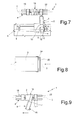
- the tape 7 continues to be wrapped even when the edge 7a passes beyond the end edge 19 thus creating a tubular envelope in which, as shown in figure 8, the last wrapped segment, indicated by numeral 21 is arranged above and axially protruding from the underlying tape segment.
- the wrapping or the spiraling of the first half of the roll 2 ends when the aforementioned tubular end envelope displays a variable length L between one hundred and twenty and two hundred and fifty millimeters, whereupon the tape 7 is cut in a known manner (figure 5) and the carriage 10 is drawn back and taken in its starting position (figure 1). Once such a position has been reached, the wrapping or the spiraling of the second half of the roll 2 starts by rotating the turret clockwise until the axis of the guide 15 is arranged in a position substantially specular to the position taken at the beginning of the wrapping of the first half of the roll 2.
- the turret 11 is rotated so that the axis of the guide forms an angle B with the plane P which is substantially equivalent to the angle A when the carriage 10 was arranged in the same axial position.
- the end of the tape 7 is advanced towards the roll 2, overlapped and glued to an initial segment of the tape 7 surrounding the middle portion 18 of the roll 2, whereupon the carriage 10 is shifted towards the right end edge 22 (figure 6), and the angle B is varied by the same law, according to which the angle A is varied, until the end edge 22 is reached and a corresponding tubular envelope exactly equivalent to the envelope obtained at edge 19 is also obtained at such an edge.
- the tape 7 is cut a second time and after having moved away the carriage 10, the aforementioned axial end envelopes are deformed towards the inside until they are taken into contact with the respective front surfaces of the roll 2, whereupon respective closing disks 25 (figure 8) which complete the packaging of the roll 2 are applied on the turned-over parts of tape and on the front surfaces.
- the end envelopes are progressively deformed in contact with the roll 2 during the forming thereof. In this manner, wrappings are obtained which are specular with respect to the plane orthogonal to the axis 3 of the roll 2 which passes through the center of the roll 2 itself.
- the wrapping both of the first half of the roll 2 and of the second half of the roll 2 itself starts by arranging the carriage 10 always in the same middle position of the roll 2 although directing the guide 15 by an angle which is advantageously equivalent to the aforementioned maximum angle.
- the wrapping or the spiraling of the two halves of the roll 2 is carried out for the initial segments having a constant angle and the angle is varied as previously described only near to the end portions of the roll 2.
- the carriage 10 is not positioned in a middle position as previously described, i.e. halfway through the roll 2 itself, but instead at an intermediate portion of the roll 2 itself and, advantageously, at an end portion. From such a position, the turret 11 is rotated so that the axis of the guide 15 forms an angle equivalent to the angle A or to the aforementioned maximum wrapping angle, whereupon the carriage is shifted towards the end portion opposite to the roll 2 and the initial angle is adjusted according to one or the other of the modes described previously.
- the roll 2 is almost totally wrapped before the tape 7 is cut and the packaging is completed with a second wrapping according to one or the other mode described previously for the wrapping of the second half of the roll 2 or, advantageously, by arranging the turret 11 so that the advancing direction forms a null angle with the plane P and carrying out a cylindrical wrapping on the uncovered part of the roll 2.
- the manufacturing of the packaging in two halves combined with the variation of the feeding angle of the tape 7 allows a more effective sealing between the tape itself and the corresponding inner disk as each tape segment overlapped to a corresponding inner segment is arranged in a position projecting with respect to the corresponding inner segment itself so that the projecting portion may conveniently be glued to the corresponding disk (figure 8).
- a correct variation of the feeding angle especially as a function of the size of the roll subsequently allows to completely wrap the roll 2 without leaving areas of the roll 2 itself uncovered and without the formation of wrinkles such as to compromise both the following handling and the aesthetic appearance.
- the quality of the packaging is then ensured by the fact that in the junction area of the two wrappings, the tapes are overlapped one on the other and are integrally connected with one another. This avoids at least partial detachments of at least one of the two wrappings and therefore avoids any problem in the following handling steps of the wrapped or packaged rolls.
- the wrapping of the roll 2 could be made by varying the feeding direction of the tape 7 in a different manner from that described by way of example, for instance by maintaining the same wrapping degree or quality as the size of the roll 2 or of the used wrapping material varies.
- the wrapping may be carried out by using two wrapping roll 2-holder carriages 10 which are distinct and independent one from the other and each supports a corresponding tape roll 2.
- the wrapping cycle time may further be reduced by synchronizing the two carriages 10 and feeding at least part of the two tapes simultaneously.
Abstract
Description
- The present invention relates to a method for the packaging of a paper roll.
- In the field of coated paper roll forming, it is known to package the roll itself by wrapping it with paper tape, once the roll has been formed, mainly to avoid the variation of the moisture content of the roll and protect the roll itself from dust and possible knocks during the following shifting of the rolls.
- Currently, the packaging of the roll is carried out by wrapping a first wrapping tape around an intermediate portion of the roll, and two further wrapping tapes around side end portions of the roll itself so as to create an intermediate cylindrical envelope and two end caps, which are in turn frontally closed by respective head disks.
- Even though the known wrapping modes of the above described type are used, they do prove poorly satisfactory for several reasons. Firstly, they require relatively long wrapping times as a consequence of the complete wrapping of the roll implying in any case the execution of three cutting operations for the wrapping tapes. This sets an insurmountable limit to the reduction of the packaging cycle time and accordingly to the increase of the number of currently wrapped rolls.
- Furthermore, the wrapping normally requires the use of tapes displaying different widths thus implying obvious complications in the handling and management of the different tape rolls.
- Finally, in some cases, portions of the roll, and in particular the areas near to the axial ends of the roll itself, result not being perfectly covered by the wrapping tape and, besides giving rise to problems following the lack of protection of the roll from moisture and dust, this implies problems for the quality of the wrapped product and an unacceptable appearance.
- It is an object of the present invention to provide a method for the packaging of paper rolls, which allows to solve the problems set forth above in a simple and cost-effective manner and, in particular, it allows a fast wrapping which is also effective and involves a low consumption of wrapping material.
- According to the present invention there is provided a method for the packaging of a paper roll displaying a symmetry axis thereof, the method comprising the steps of rotating the roll around said symmetry axis and wrapping it by means of paper tape; the wrapping comprising the operations of advancing a first paper tape towards the roll in a feeding direction forming a determined angle with a plane orthogonal to said symmetry axis and progressively translating the first tape fed in a direction parallel to said symmetry axis during the advancing towards the roll, characterized in that the wrapping comprises the further step of varying said determined angle during at least part of the translation of said first tape in the direction parallel to the symmetry axis and before cutting the first tape.
- In the above defined method, the wrapping of said first tape is preferably carried out from an intermediate portion of said roll and by progressively translating the first tape towards a longitudinal end edge of said roll; the variation of said angle being carried out during the wrapping of at least one portion of said roll, which in comprised between said intermediate portion and said longitudinal end edge.
- Advantageously, the wrapping of said first tape is carried out from an intermediate portion of said roll which is substantially arranged halfway through said roll.
- The invention will now be described with reference to the accompanying figures which show a non-limitative embodiment thereof, in which:
- Figures from 1 to 7 show a diagrammatic view - substantially in blocks - of a unit for the packaging of a paper roll arranged in different functional positions for carrying out the method according to the dictates of the present invention;
- Figure 8 shows a section view of an end portion of the wrapped
roll 2 according to the method of the present invention; and - Figure 9 shows the unit in figures from 1 to 7 in an other functional position for carrying out a variant of a step of the method according to the invention.
- In figures from 1 to 7,
numeral 1 indicates, as a whole, an intrinsically known unit for packaging apaper roll 2 displaying asymmetry axis 3. Theunit 1 comprises a support and handlingdevice 4 for supporting theroll 2 with itsaxis 3 in a horizontal position and rotating theroll 2 itself around itsaxis 3. Theunit 1 further comprises afeeding assembly 6 to advance apaper tape 7 for the packaging or wrapping towards the outer side surface of theroll 2. Theassembly 6 comprises afixed structure 8 supporting arectilinear guide 9, which extends parallelly to theaxis 3 of theroll 2 and carries a power-operatedcarriage 10 which is slidingly coupled in opposite directions. Aturret 11 is coupled to thecarriage 10, theturret 11 also being power-operated and rotatable with respect to thecarriage 10 around avertical axis 12, as well as orthogonal to theaxis 12. Theturret 11 in turn supports aroll 13 of thepackaging tape 7 arranged with an axis thereof parallel to theaxis 3 and a diagrammatically shownguide 15 integrally connected to theturret 11 itself to guide thetape 7 in arectilinear direction 16, which coincides with the axis of theguide 15 towards the side surface of theroll 2. - The
roll 2 arranged on thesupport device 4 and rotated by thedevice 4 itself, as shown in figure 1, is packaged by wrapping it with thetape 7 as follows: thecarriage 10 and theturret 11 are initially arranged in a reference or zero position, shown in figure 1, in which theguide axis 15 and therefore the feeding direction of theroll 7 form a null angle A with a plane P orthogonal to theaxis 3 and lies on theaxial center plane 3, i.e. halfway through theroll 2. At this point, theturret 11 is rotated clockwise in figure 2 until the angle A formed with the plane P (figure 2) reaches a predetermined value as a function of the length of theroll 2. - Once such an angular position has been reached, the end of the
tape 7 is connected in a known manner to amiddle portion 18 of theroll 2, whereupon theroll 2 itself is rotated around itsaxis 3 and, at the same time, thecarriage 10 is progressively translated leftwards in Figure 2, i.e. towards the same part of theleft end edge 19 of theroll 2, and theturret 11 is rotated clockwise in figure 3. In this manner, during the wrapping of themiddle portion 18, the angle A is varied and, in particular, increased until it reaches a determined maximum value, as shown in figure 3. Subsequently, the angle A is maintained constant and the wrapping continues until anedge 7a of thetape 7 is arranged near to an end portion oraxial end portion 20 of theroll 2 delimited by theedge 19. Once such a position has been reached, theturret 11 and therefore theguide 15 are progressively rotated counterclockwise, as shown in Figure 4, so that the maximum angle reached is progressively decreased until it reaches a minimum value when thetape 7 wraps theend portion 20. Thetape 7 continues to be wrapped even when theedge 7a passes beyond theend edge 19 thus creating a tubular envelope in which, as shown in figure 8, the last wrapped segment, indicated by numeral 21 is arranged above and axially protruding from the underlying tape segment. The wrapping or the spiraling of the first half of theroll 2 ends when the aforementioned tubular end envelope displays a variable length L between one hundred and twenty and two hundred and fifty millimeters, whereupon thetape 7 is cut in a known manner (figure 5) and thecarriage 10 is drawn back and taken in its starting position (figure 1). Once such a position has been reached, the wrapping or the spiraling of the second half of theroll 2 starts by rotating the turret clockwise until the axis of theguide 15 is arranged in a position substantially specular to the position taken at the beginning of the wrapping of the first half of theroll 2. In particular, theturret 11 is rotated so that the axis of the guide forms an angle B with the plane P which is substantially equivalent to the angle A when thecarriage 10 was arranged in the same axial position. At this point, the end of thetape 7 is advanced towards theroll 2, overlapped and glued to an initial segment of thetape 7 surrounding themiddle portion 18 of theroll 2, whereupon thecarriage 10 is shifted towards the right end edge 22 (figure 6), and the angle B is varied by the same law, according to which the angle A is varied, until theend edge 22 is reached and a corresponding tubular envelope exactly equivalent to the envelope obtained atedge 19 is also obtained at such an edge. At this point, thetape 7 is cut a second time and after having moved away thecarriage 10, the aforementioned axial end envelopes are deformed towards the inside until they are taken into contact with the respective front surfaces of theroll 2, whereupon respective closing disks 25 (figure 8) which complete the packaging of theroll 2 are applied on the turned-over parts of tape and on the front surfaces. According to a different embodiment, the end envelopes are progressively deformed in contact with theroll 2 during the forming thereof. In this manner, wrappings are obtained which are specular with respect to the plane orthogonal to theaxis 3 of theroll 2 which passes through the center of theroll 2 itself. - In the variant shown in figure 9, the wrapping both of the first half of the
roll 2 and of the second half of theroll 2 itself starts by arranging thecarriage 10 always in the same middle position of theroll 2 although directing theguide 15 by an angle which is advantageously equivalent to the aforementioned maximum angle. In this manner, the wrapping or the spiraling of the two halves of theroll 2 is carried out for the initial segments having a constant angle and the angle is varied as previously described only near to the end portions of theroll 2. - According to a further variant, at the beginning of the wrapping of the
roll 2, thecarriage 10 is not positioned in a middle position as previously described, i.e. halfway through theroll 2 itself, but instead at an intermediate portion of theroll 2 itself and, advantageously, at an end portion. From such a position, theturret 11 is rotated so that the axis of theguide 15 forms an angle equivalent to the angle A or to the aforementioned maximum wrapping angle, whereupon the carriage is shifted towards the end portion opposite to theroll 2 and the initial angle is adjusted according to one or the other of the modes described previously. In this manner, with the first wrapping, theroll 2 is almost totally wrapped before thetape 7 is cut and the packaging is completed with a second wrapping according to one or the other mode described previously for the wrapping of the second half of theroll 2 or, advantageously, by arranging theturret 11 so that the advancing direction forms a null angle with the plane P and carrying out a cylindrical wrapping on the uncovered part of theroll 2. - From the above, it first of all results apparent that the above described wrapping mode and, in particular, the fact that the angle of the advancing direction of the
tape 7 towards theroll 2 is varied and, in practice, the pitch of the spiraling, allows to wrap or spiral theentire roll 2 by means of two cuts of thetape 7 only. In this manner the wrapping cycle time may be decreased and the production per hour may accordingly be increased. Moreover, the fact that the feeding angle of thetape 7 towards the longitudinal edges of the roll is varied allows to increase the mechanical strength in the areas near to the longitudinal edges themselves, which are the areas more at risk in theroll 2 handling processes. Furthermore, the manufacturing of the packaging in two halves combined with the variation of the feeding angle of thetape 7 allows a more effective sealing between the tape itself and the corresponding inner disk as each tape segment overlapped to a corresponding inner segment is arranged in a position projecting with respect to the corresponding inner segment itself so that the projecting portion may conveniently be glued to the corresponding disk (figure 8). - A correct variation of the feeding angle especially as a function of the size of the roll subsequently allows to completely wrap the
roll 2 without leaving areas of theroll 2 itself uncovered and without the formation of wrinkles such as to compromise both the following handling and the aesthetic appearance. - The quality of the packaging is then ensured by the fact that in the junction area of the two wrappings, the tapes are overlapped one on the other and are integrally connected with one another. This avoids at least partial detachments of at least one of the two wrappings and therefore avoids any problem in the following handling steps of the wrapped or packaged rolls.
- From the above, it is apparent that modifications and variants may be made to the described method without however departing from the protective scope defined by the claims. In particular, the wrapping of the
roll 2 could be made by varying the feeding direction of thetape 7 in a different manner from that described by way of example, for instance by maintaining the same wrapping degree or quality as the size of theroll 2 or of the used wrapping material varies. - Furthermore, the wrapping may be carried out by using two wrapping roll 2-
holder carriages 10 which are distinct and independent one from the other and each supports acorresponding tape roll 2. In such a condition, the wrapping cycle time may further be reduced by synchronizing the twocarriages 10 and feeding at least part of the two tapes simultaneously.
Claims (14)
- A method for the packaging of a paper roll (2) displaying a symmetry axis (3) thereof, the method comprising the steps of rotating the roll around said symmetry axis and wrapping it by means of paper tape; the wrapping comprising the operations of advancing a first paper tape (7) towards the roll in a feeding direction (16) forming a determined angle (A) (B) with a plane (P) orthogonal to said symmetry axis and progressively translating the first tape fed in a direction parallel to said symmetry axis during the advancing towards the roll, characterized in that the wrapping comprises the further step of varying said determined angle during at least part of the translation of said first tape in the direction parallel to the symmetry axis and before cutting the first tape.
- A method according to claim 1, characterized in that the wrapping of said first tape is carried out from an intermediate portion (18) of said roll and by progressively translating the first tape towards a longitudinal end edge of said roll; the variation of said angle being carried out during the wrapping of at least one portion of said roll, which is comprised between said intermediate portion and said longitudinal end edge.
- A method according to claim 2, characterized in that the wrapping of said first tape is carried out from an intermediate portion of said roll which is substantially arranged halfway through of said roll.
- A method according to claim 2 or 3, characterized in that the variation of said angle is carried out at least during the wrapping of a portion of said roll near to said longitudinal end edge.
- A method according to claim 4, characterized in that said angle is adjusted so that it takes a minimum value near to said longitudinal end edge.
- A method according to any of the preceding claims, characterized in that the variation of said angle is carried out during the wrapping of said intermediate portion of said roll.
- A method according to claim 5 or 6, characterized in that during the wrapping of said intermediate portion of the roll, said angle is adjusted so that it takes a minimum value.
- A method according to any of the preceding claims, characterized in that the variation of said angle is carried out by progressively decreasing the value of said determined angle.
- A method according to one of claims from 1 to 7, characterized in that the variation of said angle is carried out by progressively increasing the value of said determined angle during the wrapping of a first portion of the roll and by progressively reducing the value of the angle at the end of the wrapping of said first portion during the wrapping of a second portion of said roll.
- A method according to claim 1, characterized in that said wrapping is carried out substantially from a first longitudinal end edge of said roll and by shifting towards a second longitudinal end edge which is opposite to said first end edge; the variation of said angle being carried out at least during the wrapping of a portion of said roll near to said second longitudinal end edge.
- A method according to any of the preceding claims, characterized in that near to each of the longitudinal end edges of the roll, said determined angle is varied so that the respective initial segment of the tape axially protrudes beyond a corresponding underlying segment of tape wrapped on the roll.
- A method according to any of the preceding claims, characterized in that the wrapping of said roll is completed by means of a single second wrapping tape; said second wrapping tape being at least partially overlapped and joined to an initial segment of said first tape and initially advanced in an advancing direction by forming a further determined angle (B) (A) with a plane (P) orthogonal to said axis; said further determined angle being varied during the completion of the wrapping of said roll.
- A method according to claim 12, characterized in that said further angle is varied by the same variation law as for the angle of said first wrapping tape so as to obtain specular wrappings with respect to a plane orthogonal to the axis of the roll and passing through the center line of the roll.
- A paper roll made according to the method according to any of the preceding claims.
Applications Claiming Priority (1)
| Application Number | Priority Date | Filing Date | Title |
|---|---|---|---|
| IT000764A ITTO20060764A1 (en) | 2006-10-23 | 2006-10-23 | METHOD FOR PACKAGING A ROLL OF PAPER MATERIAL |
Publications (2)
| Publication Number | Publication Date |
|---|---|
| EP1925555A1 true EP1925555A1 (en) | 2008-05-28 |
| EP1925555B1 EP1925555B1 (en) | 2011-01-05 |
Family
ID=39110888
Family Applications (1)
| Application Number | Title | Priority Date | Filing Date |
|---|---|---|---|
| EP07112168A Not-in-force EP1925555B1 (en) | 2006-10-23 | 2007-07-10 | A method for the packaging of a paper roll |
Country Status (4)
| Country | Link |
|---|---|
| EP (1) | EP1925555B1 (en) |
| AT (1) | ATE494222T1 (en) |
| DE (1) | DE602007011712D1 (en) |
| IT (1) | ITTO20060764A1 (en) |
Citations (3)
| Publication number | Priority date | Publication date | Assignee | Title |
|---|---|---|---|---|
| US3928939A (en) * | 1973-05-14 | 1975-12-30 | John Edwards & Associates Inc | Method of wrapping elongate cylindrical objects |
| US5203139A (en) * | 1991-06-28 | 1993-04-20 | Eastman Kodak Company | Apparatus and method for winding and wrapping rolls of web material |
| EP1449772A1 (en) * | 2003-02-24 | 2004-08-25 | Signode System Gmbh | Method and device for wrapping a film around a cylindrical roll of material |
-
2006
- 2006-10-23 IT IT000764A patent/ITTO20060764A1/en unknown
-
2007
- 2007-07-10 EP EP07112168A patent/EP1925555B1/en not_active Not-in-force
- 2007-07-10 AT AT07112168T patent/ATE494222T1/en not_active IP Right Cessation
- 2007-07-10 DE DE602007011712T patent/DE602007011712D1/en active Active
Patent Citations (3)
| Publication number | Priority date | Publication date | Assignee | Title |
|---|---|---|---|---|
| US3928939A (en) * | 1973-05-14 | 1975-12-30 | John Edwards & Associates Inc | Method of wrapping elongate cylindrical objects |
| US5203139A (en) * | 1991-06-28 | 1993-04-20 | Eastman Kodak Company | Apparatus and method for winding and wrapping rolls of web material |
| EP1449772A1 (en) * | 2003-02-24 | 2004-08-25 | Signode System Gmbh | Method and device for wrapping a film around a cylindrical roll of material |
Also Published As
| Publication number | Publication date |
|---|---|
| ATE494222T1 (en) | 2011-01-15 |
| ITTO20060764A1 (en) | 2008-04-24 |
| EP1925555B1 (en) | 2011-01-05 |
| DE602007011712D1 (en) | 2011-02-17 |
Similar Documents
| Publication | Publication Date | Title |
|---|---|---|
| KR102254063B1 (en) | Convoluted tube | |
| CN108601391B (en) | Method and machine for making rod segments for multilayer cylindrical tubular rods for use in making smoking articles | |
| US5046298A (en) | Method and apparatus for wrapping a roll with stretch wrap | |
| EP3070006B1 (en) | Wrapping method and packer machine to fold a wrapper around a group of tobacco articles | |
| EP1925555B1 (en) | A method for the packaging of a paper roll | |
| RU2739953C2 (en) | Method and device for production of roll from dough semi-product and separating sheet | |
| JPH05178364A (en) | Packaging material for packaging book, preparation thereof and manufacturing machine for it | |
| CA2182044C (en) | Device and method for wrapping a roll of continuous web material | |
| EP0105039A2 (en) | A wrapping and a method of its manufacture | |
| US20220411113A1 (en) | Pack for smoking products | |
| EP2266904A2 (en) | Foil roll with wound stiffening core, apparatus for winding the roll and method | |
| EP0431922B1 (en) | Wrapping roll-like articles | |
| CN108601392B (en) | Device and method for manufacturing a semi-finished product intended to form part of an article for smoking | |
| US3238951A (en) | Apparatus for wrapping and tipping cigars | |
| US5154040A (en) | Process and apparatus for continuous packaging under vacuum of sheets or plates | |
| EP1492710B1 (en) | Method for wrapping a roll of material and a wrapped roll of material | |
| US5236530A (en) | Edge strip control and apparatus thereof | |
| WO2018055085A1 (en) | Packaging machine with a reel with anti rotation means | |
| KR20160025941A (en) | Internal band type paper bag and the manufacturing method thereof | |
| US3199421A (en) | Container | |
| US6185909B1 (en) | Method for packaging a material web roll | |
| US20230301342A1 (en) | Modular cigar | |
| US20210197992A1 (en) | Segmented wrapping films and related methods | |
| JPH0582048B2 (en) | ||
| GB0523891D0 (en) | Variable speed wrapping |
Legal Events
| Date | Code | Title | Description |
|---|---|---|---|
| PUAI | Public reference made under article 153(3) epc to a published international application that has entered the european phase |
Free format text: ORIGINAL CODE: 0009012 |
|
| AK | Designated contracting states |
Kind code of ref document: A1 Designated state(s): AT BE BG CH CY CZ DE DK EE ES FI FR GB GR HU IE IS IT LI LT LU LV MC MT NL PL PT RO SE SI SK TR |
|
| AX | Request for extension of the european patent |
Extension state: AL BA HR MK RS |
|
| 17P | Request for examination filed |
Effective date: 20081128 |
|
| 17Q | First examination report despatched |
Effective date: 20090107 |
|
| AKX | Designation fees paid |
Designated state(s): AT BE BG CH CY CZ DE DK EE ES FI FR GB GR HU IE IS IT LI LT LU LV MC MT NL PL PT RO SE SI SK TR |
|
| GRAP | Despatch of communication of intention to grant a patent |
Free format text: ORIGINAL CODE: EPIDOSNIGR1 |
|
| GRAS | Grant fee paid |
Free format text: ORIGINAL CODE: EPIDOSNIGR3 |
|
| GRAA | (expected) grant |
Free format text: ORIGINAL CODE: 0009210 |
|
| AK | Designated contracting states |
Kind code of ref document: B1 Designated state(s): AT BE BG CH CY CZ DE DK EE ES FI FR GB GR HU IE IS IT LI LT LU LV MC MT NL PL PT RO SE SI SK TR |
|
| REG | Reference to a national code |
Ref country code: GB Ref legal event code: FG4D |
|
| REG | Reference to a national code |
Ref country code: CH Ref legal event code: EP |
|
| REG | Reference to a national code |
Ref country code: IE Ref legal event code: FG4D |
|
| REF | Corresponds to: |
Ref document number: 602007011712 Country of ref document: DE Date of ref document: 20110217 Kind code of ref document: P |
|
| REG | Reference to a national code |
Ref country code: DE Ref legal event code: R096 Ref document number: 602007011712 Country of ref document: DE Effective date: 20110217 |
|
| REG | Reference to a national code |
Ref country code: CH Ref legal event code: NV Representative=s name: ANDRE ROLAND S.A. |
|
| REG | Reference to a national code |
Ref country code: NL Ref legal event code: VDEP Effective date: 20110105 |
|
| PG25 | Lapsed in a contracting state [announced via postgrant information from national office to epo] |
Ref country code: SI Free format text: LAPSE BECAUSE OF FAILURE TO SUBMIT A TRANSLATION OF THE DESCRIPTION OR TO PAY THE FEE WITHIN THE PRESCRIBED TIME-LIMIT Effective date: 20110105 |
|
| LTIE | Lt: invalidation of european patent or patent extension |
Effective date: 20110105 |
|
| PG25 | Lapsed in a contracting state [announced via postgrant information from national office to epo] |
Ref country code: PT Free format text: LAPSE BECAUSE OF FAILURE TO SUBMIT A TRANSLATION OF THE DESCRIPTION OR TO PAY THE FEE WITHIN THE PRESCRIBED TIME-LIMIT Effective date: 20110505 Ref country code: GR Free format text: LAPSE BECAUSE OF FAILURE TO SUBMIT A TRANSLATION OF THE DESCRIPTION OR TO PAY THE FEE WITHIN THE PRESCRIBED TIME-LIMIT Effective date: 20110406 Ref country code: LT Free format text: LAPSE BECAUSE OF FAILURE TO SUBMIT A TRANSLATION OF THE DESCRIPTION OR TO PAY THE FEE WITHIN THE PRESCRIBED TIME-LIMIT Effective date: 20110105 Ref country code: SE Free format text: LAPSE BECAUSE OF FAILURE TO SUBMIT A TRANSLATION OF THE DESCRIPTION OR TO PAY THE FEE WITHIN THE PRESCRIBED TIME-LIMIT Effective date: 20110105 Ref country code: ES Free format text: LAPSE BECAUSE OF FAILURE TO SUBMIT A TRANSLATION OF THE DESCRIPTION OR TO PAY THE FEE WITHIN THE PRESCRIBED TIME-LIMIT Effective date: 20110416 Ref country code: LV Free format text: LAPSE BECAUSE OF FAILURE TO SUBMIT A TRANSLATION OF THE DESCRIPTION OR TO PAY THE FEE WITHIN THE PRESCRIBED TIME-LIMIT Effective date: 20110105 Ref country code: IS Free format text: LAPSE BECAUSE OF FAILURE TO SUBMIT A TRANSLATION OF THE DESCRIPTION OR TO PAY THE FEE WITHIN THE PRESCRIBED TIME-LIMIT Effective date: 20110505 |
|
| PG25 | Lapsed in a contracting state [announced via postgrant information from national office to epo] |
Ref country code: PL Free format text: LAPSE BECAUSE OF FAILURE TO SUBMIT A TRANSLATION OF THE DESCRIPTION OR TO PAY THE FEE WITHIN THE PRESCRIBED TIME-LIMIT Effective date: 20110105 Ref country code: AT Free format text: LAPSE BECAUSE OF FAILURE TO SUBMIT A TRANSLATION OF THE DESCRIPTION OR TO PAY THE FEE WITHIN THE PRESCRIBED TIME-LIMIT Effective date: 20110105 Ref country code: BG Free format text: LAPSE BECAUSE OF FAILURE TO SUBMIT A TRANSLATION OF THE DESCRIPTION OR TO PAY THE FEE WITHIN THE PRESCRIBED TIME-LIMIT Effective date: 20110405 Ref country code: FI Free format text: LAPSE BECAUSE OF FAILURE TO SUBMIT A TRANSLATION OF THE DESCRIPTION OR TO PAY THE FEE WITHIN THE PRESCRIBED TIME-LIMIT Effective date: 20110105 Ref country code: CY Free format text: LAPSE BECAUSE OF FAILURE TO SUBMIT A TRANSLATION OF THE DESCRIPTION OR TO PAY THE FEE WITHIN THE PRESCRIBED TIME-LIMIT Effective date: 20110105 Ref country code: NL Free format text: LAPSE BECAUSE OF FAILURE TO SUBMIT A TRANSLATION OF THE DESCRIPTION OR TO PAY THE FEE WITHIN THE PRESCRIBED TIME-LIMIT Effective date: 20110105 |
|
| PG25 | Lapsed in a contracting state [announced via postgrant information from national office to epo] |
Ref country code: EE Free format text: LAPSE BECAUSE OF FAILURE TO SUBMIT A TRANSLATION OF THE DESCRIPTION OR TO PAY THE FEE WITHIN THE PRESCRIBED TIME-LIMIT Effective date: 20110105 Ref country code: DK Free format text: LAPSE BECAUSE OF FAILURE TO SUBMIT A TRANSLATION OF THE DESCRIPTION OR TO PAY THE FEE WITHIN THE PRESCRIBED TIME-LIMIT Effective date: 20110105 |
|
| PLBE | No opposition filed within time limit |
Free format text: ORIGINAL CODE: 0009261 |
|
| STAA | Information on the status of an ep patent application or granted ep patent |
Free format text: STATUS: NO OPPOSITION FILED WITHIN TIME LIMIT |
|
| PG25 | Lapsed in a contracting state [announced via postgrant information from national office to epo] |
Ref country code: CZ Free format text: LAPSE BECAUSE OF FAILURE TO SUBMIT A TRANSLATION OF THE DESCRIPTION OR TO PAY THE FEE WITHIN THE PRESCRIBED TIME-LIMIT Effective date: 20110105 Ref country code: SK Free format text: LAPSE BECAUSE OF FAILURE TO SUBMIT A TRANSLATION OF THE DESCRIPTION OR TO PAY THE FEE WITHIN THE PRESCRIBED TIME-LIMIT Effective date: 20110105 Ref country code: RO Free format text: LAPSE BECAUSE OF FAILURE TO SUBMIT A TRANSLATION OF THE DESCRIPTION OR TO PAY THE FEE WITHIN THE PRESCRIBED TIME-LIMIT Effective date: 20110105 |
|
| 26N | No opposition filed |
Effective date: 20111006 |
|
| PG25 | Lapsed in a contracting state [announced via postgrant information from national office to epo] |
Ref country code: MT Free format text: LAPSE BECAUSE OF FAILURE TO SUBMIT A TRANSLATION OF THE DESCRIPTION OR TO PAY THE FEE WITHIN THE PRESCRIBED TIME-LIMIT Effective date: 20110105 Ref country code: IT Free format text: LAPSE BECAUSE OF FAILURE TO SUBMIT A TRANSLATION OF THE DESCRIPTION OR TO PAY THE FEE WITHIN THE PRESCRIBED TIME-LIMIT Effective date: 20110105 |
|
| REG | Reference to a national code |
Ref country code: CH Ref legal event code: PCAR Free format text: ANDRE ROLAND S.A.;CASE POSTALE 5107;1002 LAUSANNE (CH) |
|
| REG | Reference to a national code |
Ref country code: DE Ref legal event code: R097 Ref document number: 602007011712 Country of ref document: DE Effective date: 20111006 |
|
| PG25 | Lapsed in a contracting state [announced via postgrant information from national office to epo] |
Ref country code: MC Free format text: LAPSE BECAUSE OF NON-PAYMENT OF DUE FEES Effective date: 20110731 |
|
| GBPC | Gb: european patent ceased through non-payment of renewal fee |
Effective date: 20110710 |
|
| REG | Reference to a national code |
Ref country code: IE Ref legal event code: MM4A |
|
| PG25 | Lapsed in a contracting state [announced via postgrant information from national office to epo] |
Ref country code: GB Free format text: LAPSE BECAUSE OF NON-PAYMENT OF DUE FEES Effective date: 20110710 |
|
| PG25 | Lapsed in a contracting state [announced via postgrant information from national office to epo] |
Ref country code: IE Free format text: LAPSE BECAUSE OF NON-PAYMENT OF DUE FEES Effective date: 20110710 |
|
| PG25 | Lapsed in a contracting state [announced via postgrant information from national office to epo] |
Ref country code: LU Free format text: LAPSE BECAUSE OF NON-PAYMENT OF DUE FEES Effective date: 20110710 |
|
| PG25 | Lapsed in a contracting state [announced via postgrant information from national office to epo] |
Ref country code: TR Free format text: LAPSE BECAUSE OF FAILURE TO SUBMIT A TRANSLATION OF THE DESCRIPTION OR TO PAY THE FEE WITHIN THE PRESCRIBED TIME-LIMIT Effective date: 20110105 |
|
| PG25 | Lapsed in a contracting state [announced via postgrant information from national office to epo] |
Ref country code: HU Free format text: LAPSE BECAUSE OF FAILURE TO SUBMIT A TRANSLATION OF THE DESCRIPTION OR TO PAY THE FEE WITHIN THE PRESCRIBED TIME-LIMIT Effective date: 20110105 |
|
| PGFP | Annual fee paid to national office [announced via postgrant information from national office to epo] |
Ref country code: CH Payment date: 20130712 Year of fee payment: 7 |
|
| PGFP | Annual fee paid to national office [announced via postgrant information from national office to epo] |
Ref country code: BE Payment date: 20140714 Year of fee payment: 8 |
|
| REG | Reference to a national code |
Ref country code: CH Ref legal event code: PL |
|
| PG25 | Lapsed in a contracting state [announced via postgrant information from national office to epo] |
Ref country code: LI Free format text: LAPSE BECAUSE OF NON-PAYMENT OF DUE FEES Effective date: 20140731 Ref country code: CH Free format text: LAPSE BECAUSE OF NON-PAYMENT OF DUE FEES Effective date: 20140731 |
|
| REG | Reference to a national code |
Ref country code: FR Ref legal event code: PLFP Year of fee payment: 10 |
|
| REG | Reference to a national code |
Ref country code: DE Ref legal event code: R082 Ref document number: 602007011712 Country of ref document: DE Representative=s name: GLAWE DELFS MOLL PARTNERSCHAFT MBB VON PATENT-, DE |
|
| REG | Reference to a national code |
Ref country code: FR Ref legal event code: PLFP Year of fee payment: 11 |
|
| PG25 | Lapsed in a contracting state [announced via postgrant information from national office to epo] |
Ref country code: BE Free format text: LAPSE BECAUSE OF NON-PAYMENT OF DUE FEES Effective date: 20150731 |
|
| PGFP | Annual fee paid to national office [announced via postgrant information from national office to epo] |
Ref country code: FR Payment date: 20170727 Year of fee payment: 11 |
|
| PG25 | Lapsed in a contracting state [announced via postgrant information from national office to epo] |
Ref country code: FR Free format text: LAPSE BECAUSE OF NON-PAYMENT OF DUE FEES Effective date: 20180731 |
|
| PGFP | Annual fee paid to national office [announced via postgrant information from national office to epo] |
Ref country code: DE Payment date: 20190731 Year of fee payment: 13 |
|
| REG | Reference to a national code |
Ref country code: DE Ref legal event code: R119 Ref document number: 602007011712 Country of ref document: DE |
|
| PG25 | Lapsed in a contracting state [announced via postgrant information from national office to epo] |
Ref country code: DE Free format text: LAPSE BECAUSE OF NON-PAYMENT OF DUE FEES Effective date: 20210202 |