EP1928523B1 - Auto-injection device with needle protecting cap having outer and inner sleeves - Google Patents
Auto-injection device with needle protecting cap having outer and inner sleeves Download PDFInfo
- Publication number
- EP1928523B1 EP1928523B1 EP05787023A EP05787023A EP1928523B1 EP 1928523 B1 EP1928523 B1 EP 1928523B1 EP 05787023 A EP05787023 A EP 05787023A EP 05787023 A EP05787023 A EP 05787023A EP 1928523 B1 EP1928523 B1 EP 1928523B1
- Authority
- EP
- European Patent Office
- Prior art keywords
- syringe
- injection device
- trigger
- housing
- drive
- Prior art date
- Legal status (The legal status is an assumption and is not a legal conclusion. Google has not performed a legal analysis and makes no representation as to the accuracy of the status listed.)
- Active
Links
- 238000002347 injection Methods 0.000 title claims abstract description 57
- 239000007924 injection Substances 0.000 title claims abstract description 57
- 230000000717 retained effect Effects 0.000 claims description 11
- 230000000994 depressogenic effect Effects 0.000 abstract description 10
- 239000012530 fluid Substances 0.000 description 18
- 239000003814 drug Substances 0.000 description 14
- 229940079593 drug Drugs 0.000 description 14
- 238000013016 damping Methods 0.000 description 13
- 230000002706 hydrostatic effect Effects 0.000 description 8
- 230000003068 static effect Effects 0.000 description 6
- 244000273618 Sphenoclea zeylanica Species 0.000 description 2
- 230000006835 compression Effects 0.000 description 2
- 238000007906 compression Methods 0.000 description 2
- 230000036512 infertility Effects 0.000 description 2
- 241000180579 Arca Species 0.000 description 1
- 238000004891 communication Methods 0.000 description 1
- 230000002500 effect on skin Effects 0.000 description 1
- 238000005516 engineering process Methods 0.000 description 1
- 208000015181 infectious disease Diseases 0.000 description 1
- 230000014759 maintenance of location Effects 0.000 description 1
- 238000000034 method Methods 0.000 description 1
- 230000035939 shock Effects 0.000 description 1
- 238000007920 subcutaneous administration Methods 0.000 description 1
- 230000000007 visual effect Effects 0.000 description 1
Images


Classifications
-
- A—HUMAN NECESSITIES
- A61—MEDICAL OR VETERINARY SCIENCE; HYGIENE
- A61M—DEVICES FOR INTRODUCING MEDIA INTO, OR ONTO, THE BODY; DEVICES FOR TRANSDUCING BODY MEDIA OR FOR TAKING MEDIA FROM THE BODY; DEVICES FOR PRODUCING OR ENDING SLEEP OR STUPOR
- A61M5/00—Devices for bringing media into the body in a subcutaneous, intra-vascular or intramuscular way; Accessories therefor, e.g. filling or cleaning devices, arm-rests
- A61M5/178—Syringes
- A61M5/20—Automatic syringes, e.g. with automatically actuated piston rod, with automatic needle injection, filling automatically
- A61M5/2033—Spring-loaded one-shot injectors with or without automatic needle insertion
-
- A—HUMAN NECESSITIES
- A61—MEDICAL OR VETERINARY SCIENCE; HYGIENE
- A61M—DEVICES FOR INTRODUCING MEDIA INTO, OR ONTO, THE BODY; DEVICES FOR TRANSDUCING BODY MEDIA OR FOR TAKING MEDIA FROM THE BODY; DEVICES FOR PRODUCING OR ENDING SLEEP OR STUPOR
- A61M5/00—Devices for bringing media into the body in a subcutaneous, intra-vascular or intramuscular way; Accessories therefor, e.g. filling or cleaning devices, arm-rests
- A61M5/178—Syringes
- A61M5/31—Details
- A61M5/32—Needles; Details of needles pertaining to their connection with syringe or hub; Accessories for bringing the needle into, or holding the needle on, the body; Devices for protection of needles
- A61M5/3202—Devices for protection of the needle before use, e.g. caps
-
- A—HUMAN NECESSITIES
- A61—MEDICAL OR VETERINARY SCIENCE; HYGIENE
- A61M—DEVICES FOR INTRODUCING MEDIA INTO, OR ONTO, THE BODY; DEVICES FOR TRANSDUCING BODY MEDIA OR FOR TAKING MEDIA FROM THE BODY; DEVICES FOR PRODUCING OR ENDING SLEEP OR STUPOR
- A61M5/00—Devices for bringing media into the body in a subcutaneous, intra-vascular or intramuscular way; Accessories therefor, e.g. filling or cleaning devices, arm-rests
- A61M5/178—Syringes
- A61M5/20—Automatic syringes, e.g. with automatically actuated piston rod, with automatic needle injection, filling automatically
- A61M2005/2006—Having specific accessories
- A61M2005/2013—Having specific accessories triggering of discharging means by contact of injector with patient body
-
- A—HUMAN NECESSITIES
- A61—MEDICAL OR VETERINARY SCIENCE; HYGIENE
- A61M—DEVICES FOR INTRODUCING MEDIA INTO, OR ONTO, THE BODY; DEVICES FOR TRANSDUCING BODY MEDIA OR FOR TAKING MEDIA FROM THE BODY; DEVICES FOR PRODUCING OR ENDING SLEEP OR STUPOR
- A61M5/00—Devices for bringing media into the body in a subcutaneous, intra-vascular or intramuscular way; Accessories therefor, e.g. filling or cleaning devices, arm-rests
- A61M5/178—Syringes
- A61M5/20—Automatic syringes, e.g. with automatically actuated piston rod, with automatic needle injection, filling automatically
- A61M2005/206—With automatic needle insertion
-
- A—HUMAN NECESSITIES
- A61—MEDICAL OR VETERINARY SCIENCE; HYGIENE
- A61M—DEVICES FOR INTRODUCING MEDIA INTO, OR ONTO, THE BODY; DEVICES FOR TRANSDUCING BODY MEDIA OR FOR TAKING MEDIA FROM THE BODY; DEVICES FOR PRODUCING OR ENDING SLEEP OR STUPOR
- A61M5/00—Devices for bringing media into the body in a subcutaneous, intra-vascular or intramuscular way; Accessories therefor, e.g. filling or cleaning devices, arm-rests
- A61M5/178—Syringes
- A61M5/20—Automatic syringes, e.g. with automatically actuated piston rod, with automatic needle injection, filling automatically
- A61M2005/2073—Automatic syringes, e.g. with automatically actuated piston rod, with automatic needle injection, filling automatically preventing premature release, e.g. by making use of a safety lock
- A61M2005/208—Release is possible only when device is pushed against the skin, e.g. using a trigger which is blocked or inactive when the device is not pushed against the skin
-
- A—HUMAN NECESSITIES
- A61—MEDICAL OR VETERINARY SCIENCE; HYGIENE
- A61M—DEVICES FOR INTRODUCING MEDIA INTO, OR ONTO, THE BODY; DEVICES FOR TRANSDUCING BODY MEDIA OR FOR TAKING MEDIA FROM THE BODY; DEVICES FOR PRODUCING OR ENDING SLEEP OR STUPOR
- A61M5/00—Devices for bringing media into the body in a subcutaneous, intra-vascular or intramuscular way; Accessories therefor, e.g. filling or cleaning devices, arm-rests
- A61M5/178—Syringes
- A61M5/31—Details
- A61M2005/3103—Leak prevention means for distal end of syringes, i.e. syringe end for mounting a needle
- A61M2005/3107—Leak prevention means for distal end of syringes, i.e. syringe end for mounting a needle for needles
- A61M2005/3109—Caps sealing the needle bore by use of, e.g. air-hardening adhesive, elastomer or epoxy resin
-
- A—HUMAN NECESSITIES
- A61—MEDICAL OR VETERINARY SCIENCE; HYGIENE
- A61M—DEVICES FOR INTRODUCING MEDIA INTO, OR ONTO, THE BODY; DEVICES FOR TRANSDUCING BODY MEDIA OR FOR TAKING MEDIA FROM THE BODY; DEVICES FOR PRODUCING OR ENDING SLEEP OR STUPOR
- A61M5/00—Devices for bringing media into the body in a subcutaneous, intra-vascular or intramuscular way; Accessories therefor, e.g. filling or cleaning devices, arm-rests
- A61M5/178—Syringes
- A61M5/31—Details
- A61M2005/3117—Means preventing contamination of the medicament compartment of a syringe
- A61M2005/3118—Means preventing contamination of the medicament compartment of a syringe via the distal end of a syringe, i.e. syringe end for mounting a needle cannula
- A61M2005/312—Means preventing contamination of the medicament compartment of a syringe via the distal end of a syringe, i.e. syringe end for mounting a needle cannula comprising sealing means, e.g. severable caps, to be removed prior to injection by, e.g. tearing or twisting
-
- A—HUMAN NECESSITIES
- A61—MEDICAL OR VETERINARY SCIENCE; HYGIENE
- A61M—DEVICES FOR INTRODUCING MEDIA INTO, OR ONTO, THE BODY; DEVICES FOR TRANSDUCING BODY MEDIA OR FOR TAKING MEDIA FROM THE BODY; DEVICES FOR PRODUCING OR ENDING SLEEP OR STUPOR
- A61M5/00—Devices for bringing media into the body in a subcutaneous, intra-vascular or intramuscular way; Accessories therefor, e.g. filling or cleaning devices, arm-rests
- A61M5/178—Syringes
- A61M5/31—Details
- A61M5/32—Needles; Details of needles pertaining to their connection with syringe or hub; Accessories for bringing the needle into, or holding the needle on, the body; Devices for protection of needles
- A61M5/3205—Apparatus for removing or disposing of used needles or syringes, e.g. containers; Means for protection against accidental injuries from used needles
- A61M5/321—Means for protection against accidental injuries by used needles
- A61M5/3213—Caps placed axially onto the needle, e.g. equipped with finger protection guards
- A61M2005/3215—Tools enabling the cap placement
-
- A—HUMAN NECESSITIES
- A61—MEDICAL OR VETERINARY SCIENCE; HYGIENE
- A61M—DEVICES FOR INTRODUCING MEDIA INTO, OR ONTO, THE BODY; DEVICES FOR TRANSDUCING BODY MEDIA OR FOR TAKING MEDIA FROM THE BODY; DEVICES FOR PRODUCING OR ENDING SLEEP OR STUPOR
- A61M5/00—Devices for bringing media into the body in a subcutaneous, intra-vascular or intramuscular way; Accessories therefor, e.g. filling or cleaning devices, arm-rests
- A61M5/178—Syringes
- A61M5/31—Details
- A61M5/32—Needles; Details of needles pertaining to their connection with syringe or hub; Accessories for bringing the needle into, or holding the needle on, the body; Devices for protection of needles
- A61M5/3202—Devices for protection of the needle before use, e.g. caps
- A61M5/3204—Needle cap remover, i.e. devices to dislodge protection cover from needle or needle hub, e.g. deshielding devices
-
- A—HUMAN NECESSITIES
- A61—MEDICAL OR VETERINARY SCIENCE; HYGIENE
- A61M—DEVICES FOR INTRODUCING MEDIA INTO, OR ONTO, THE BODY; DEVICES FOR TRANSDUCING BODY MEDIA OR FOR TAKING MEDIA FROM THE BODY; DEVICES FOR PRODUCING OR ENDING SLEEP OR STUPOR
- A61M5/00—Devices for bringing media into the body in a subcutaneous, intra-vascular or intramuscular way; Accessories therefor, e.g. filling or cleaning devices, arm-rests
- A61M5/178—Syringes
- A61M5/31—Details
- A61M5/32—Needles; Details of needles pertaining to their connection with syringe or hub; Accessories for bringing the needle into, or holding the needle on, the body; Devices for protection of needles
- A61M5/3205—Apparatus for removing or disposing of used needles or syringes, e.g. containers; Means for protection against accidental injuries from used needles
- A61M5/321—Means for protection against accidental injuries by used needles
- A61M5/3243—Means for protection against accidental injuries by used needles being axially-extensible, e.g. protective sleeves coaxially slidable on the syringe barrel
- A61M5/326—Fully automatic sleeve extension, i.e. in which triggering of the sleeve does not require a deliberate action by the user
Definitions
- the present invention relates to an injection device of the type that receives a syringe, extends it, discharges its contents and then retracts it automatically
- Devices of this general description are shown in US 5,599,309 ; WO 95/35126 , WO 05/070481 and EP-A-0 516 473 and tend to employ a drive spring and some form of release mechanism that releases the syringe from the influence of the drive spring once its contents are supposed to have been discharged, to allow it to be retracted by a return spring.
- the return spring is relatively weak, since its restoring force must be overcome by the drive spring, even while the drive spring is doing work on the various components of the injector device and the syringe during an injection cycle. This may give rise to a problem when the injection device is used with sealed hypodermic syringes, which typically have a hermetically sealed cover or "boot” that covers the hypodermic needle and maintains the sterility of the syringe contents.
- boot it is necessary to maintain the sterility of the syringe contents up to the point of administration, which devices that are designed to be disposable, as many will be, means that the boot must be removed with the syringe inside the injection device.
- the action required to remove the boot from the syringe is simply to pull the boot away from the syringe, which requires a force in excess of 20N. This is significantly greater than the restoring force of the return spring, so the syringe will be pulled out of the injection device as the boot is removed and, when the boot comes away, it will snap back into place. This is not the best way to handle the syringe. The shock could damage it, the needle could be damaged and there may he problems re-engaging the syringe with those components of the injection device designed to act upon it.
- the infection devices of the present invention are designed to deal with these problems.
- An injection device comprises: a housing adapted to receive a syringe having a discharge nozzle and having a boot that covers its discharge nozzle, so that the syringe is movable between a retracted position in which the discharge nozzle is contained within the housing and an extended position in which the discharge nozzle extends from the housing through an exit aperture, the housing including means for biasing the syringe from its extended position to its retracted position; a releasable locking mechanism that retains the syringe in its retracted positions; and a housing closure member that can occupy a first position, in which it locates on the housing and prevents the locking mechanism from being released, and a second position, in which it does not prevent the.
- the device further comprises an actuator; a drive that is acted upon by the actuator and in turn acts upon the syringe to advance it from its retracted position to its extended position and discharge its contents through the discharge nozzle; a release mechanism operable to release the locking mechanism, thus allowing the syringes to he advanced by the actuator from its retracted position to its extended position, and in which the first position or the housing closure member is one in which it prevents the release mechanism from being operated; and a return mechanism, activated when the drive has reached a nominal return position, to release the syringe from the action of the actuator, whereupon the biasing means restores the syringe to its retracted position.
- the locking mechanism is characterised in that it comprises a latch member that is located within the housing and is biased into a position in which it engages
- the housing closure member When the housing closure member is in its first position, it not only locates on the housing and engages the boot, but it also prevents the locking mechanism from being released. Thus, the syringe is locked into its retracted position and cannot be driven forwards. When the housing closure member is moved, it takes the boot with it, during which process the locking mechanism still prevents the syringe from moving. Afterwards, the locking mechanism can be released as required, allowing the syringe to be driven forwards when the device is used. Therefore, the syringe can move forwards only once the boot has been removed, not during its removal.
- the housing closure member when it is in its first position, it closes the exit aperture to the discharge nozzle.
- the closure member may he removable.
- the first position of the housing closure member is one in which it locates on the housing and the second position is one in which it does not.
- the housing closure member could be a cap that locates onto the housing by means of a thread.
- the release mechanism may be a primary member movable between locking and releasing positions, the first position of the housing closure member being one in which it covers the primary member.
- a particularly effective arrangement is one in which the locking position of the primary member is one in which it projects from the exit aperture and the releasing position is one in which it does not projects from the exit aperture or projects from it to a lesser extent.
- the primary member may he moved from its locking position to its releasing positions by bringing the end of the injection device into contact with the skin at the injection site. Apart from anything else, this ensures that the injection device is optimally positioned relative to the injection site before the injection cycle can begin.
- a primary member in the form of a sleeve allows a relatively large arca to contact the skin and allows the discharge nozzle of the syringe to be advanced and retracted within it. In the case of a hypodermic syringe, the sleeve will shroud the needle from view, which is a good idea for the squeamish, particularly those who have to administer to themselves.
- the primary member mentioned above may include a latch opening through which the latch member projects before it engages the locking surface, the primary member acting as a cam and the latch member as a cam follower, so that movement of the primary member from its locking position to its releasing position causes the latch member to disengage from the locking surface.
- the latch member may include a ramped surface against which a surface of the primary member acts to disengage it from the locking surface.
- the injection device may further comprise a trigger movable from a rest position, in which it causes the drive to be retained in a positions corresponding to the retracted position of the syringe, to an active position, in which it no longer causes the drive to he so retained, thus allowing it to be advanced by the actuator and in turn to advance the syringe, from its retracted position to its extended position and discharge its contents through the discharge nozzle; and an interlock member movable between a locking position, at which it prevents movement of the trigger from its rest position to its active position, and a releasing positions, at which it allows movement of the trigger from its rest position to its active position, the trigger thereafter being retained in its active positions.
- Such a device provides a visual indication that it is either ready to use or has been used. If it is ready for use, the trigger will he in its rest position. If it has been used, the trigger will he in its active position. These positions can be discriminated by the user. Moreover, the device incorporated the mechanism for achieving this result into a safety interlock mechanism, in the interests of simplicity.
- the trigger may comprises a locking member that, in the rest position of the trigger, engages a locking surface of the drive and, in the active position, docs not.
- the interlock member may comprises a primary member, the locking position of the interlock member being one in which the primary member projects from the exit aperture and tha releasing position being one in which the primary member does not project from the exit aperture or projects from it to a lesser extent.
- the interlock member may be moved from its locking position to its releasing position by bringing the end of the injection device into contact with the skin at the injection site. Apart from anything else, this ensures that the injection device is optimally positioned relative to the injection site before the injection cycle can begin.
- a primary member in the form of a sleeve allows a relatively large area to contact the skin and allows the discharge nozzle of the syringe to be advanced and retracted within it. In the case of a hypodermic syringe, the sleeve will shroud the needle from view, which is to good idea for the squeamish, particularly those who have to administer to themselves.
- the locking of the trigger in its rest position may be achieved as follows.
- the trigger and the interlock member include a projection and an aperture, the projection being in register with the aperture when the interlock member is in its releasing position, but not otherwise. This allows the trigger to move from its rest position to its active position by movement of the projection into the aperture.
- the projection may be on the trigger and the aperture is in the interlock member.
- the retention of the trigger in its active position may be achieved as follows.
- the trigger and another component of the device include a latching projection and a corresponding latching surface against which the latching projection latches when the trigger is in its active position,
- the latching projection may be on the trigger.
- This other component or the device is preferably the interlock member.
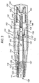
- Fig. 1 shows the end of an injection device housing 112 and a cap 111.
- the cap 111 includes a thread 113 that cooperates with a corresponding thread 115 on the end of the housing.
- the end of the housing 112 has an exit aperture 128, from which the end of a sleeve 119 can be seen to emerge.
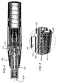
- the cap 111 has a central boss 121 that fits within the sleeve 119 when the cap 111 is installed on the housing 112, as can be seen in fig. 2 .
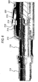
- Fig. 3 shows an injection device 110 in more detail.
- the housing 112 contains a hypodermic syringe 114 of conventional types including a syringe body 116 terminating at one end in a hypodermic needle 118 and at the other in a flange 120.
- the conventional plunger that would normally be used to discharge the contents of the syringe 114 manually has been removed and replaced with a drive element 134 that terminates in a bung 122.
- the bung 122 constrains a drug 124 to be administered within the syringe body 116. Whilst the syringe illustrated is of hypodermic type, this need not necessarily be so.
- Transcutaneous or ballistic dermal and subcutaneous syringes may also be used with the injection device of the present invention.
- the housing includes a return spring 126 that biases the syringe 114 from an extended position in which the needle 118 extends from an aperture 128 in the housing 112 to a retracted position in which the discharge nozzle 118 is contained within the housing 112.
- the return spring 126 acts on the syringe 114 via a syringe carrier 127.
- an actuator which here takes the form of a compression drive spring 130.
- Drive from the drive spring 130 is transmitted via a multi-component drive to the syringe 114 to advance it from its retracted position to its extended position and discharge its contents through the needle 118.
- the drive accomplishes this task by acting directly on the drug 124 and the syringe 114.
- Hydrostatic forces acting through the drug 124 and, to a lesser extent, static friction between the bung 122 and the syringe body 116 initially ensure that they advance together, until the return spring 126 bottoms out or the syringe body 116 meets some other obstruction (not shown) that retards its motion.
- the multi-component drive between the drive spring 130 and the syringe 114 consists of three principal components.
- a drive sleeve 131 takes drive from the drive spring 130 and transmits it to flexible latch arms 133 on a first drive element 132. This in turn transmits drive via flexible latch arms 135 to a second drive element, the drive element 134 already mentioned.
- the first drive element 132 includes a hollow stem 140, the inner cavity of which forms a collection chamber 142 in communication with a vent 144 that extends from the collection chamber through the end of the stem 140.
- the second drive element 134 includes a blind bore 146 that is open at one end to receive the stem 140 and closed at the other. As can be seen, the bore 146 and the stem 140 defining a fluid reservoir 148, within which a damping fluid is contained.
- a trigger (not shown) is provided that, when operated, serves to decouple the drive sleeve 131 from the housing 112, allowing it to move relative to the housing 112 under the influence of the drive spring 130.
- the operation of the device is then as follows.
- the drive spring 130 moves the drive sleeve 131, the drive sleeve 131 moves the first drive element 32 and the first drive element 132 moves the second drive element 134, in each case by acting through the flexible latch arms 133, 135.
- the second drive element 134 moves and, by virtue of static friction and hydrostatic forces acting through the drug 124 to be administered, moves the syringe body 116 against the action of the return spring 126.
- the return spring 126 compresses and the hypodermic needle 118 emerges from the exit aperture 128 of the housing 112. This continues until the return spring 126 bottoms out or the syringe body 116 meets some other obstruction (not shown) that retards its motion.
- the flexible latch arms 135 linking the first and second drive elements 132, 134 reach a constriction 137 within the housing 112.
- the constriction 137 moves the flexible latch arms 135 inwards from the position shown to a position at which they no longer couple the first drive element 132 to the second drive element 134, aided by the bevelled surfaces on the constriction 137.
- the first drive element 132 acts no longer on the second drive element 134, allowing the first drive element 132 to move relative to the second drive element 134.
- the volume of the reservoir 146 will tend to decrease as the first drive element 132 moves relative to the second drive element 134 when the former is acted upon by the drive spring 130.
- the reservoir 148 collapses damping fluid is forced through the vent 144 into the collection chamber 142.
- the force exerted by the drive spring 130 does work on the damping fluid, causing it to flow though the constriction formed by the vent 144, and also acts hydrostatically through the fluid and through friction between the first and second drive elements 132, 134, thence via the second drive element 134. Losses associated with the flow of the damping fluid do not attenuate the force acting on the body of the syringe to a great extent.
- the return spring 126 remains compressed and the hypodermic needle remains extended.
- the second drive element 134 completes its travel within the syringe body 116 and can go no further. At this point, the contents of the syringe 114 are completely discharged and the force exerted by the drive spring 130 acts to retain the second drive element 134 in its terminal position and to continue to cause the damping fluid to flow though the vent 144, allowing the first drive element 132 to continue its movement.
- the flexible latch arms 133 linking the drive sleeve 131 with the first drive element 132 reach another constriction 139 within the housing 112.
- the constriction 139 moves the flexible latch arms 133 inwards from the position shown to a position at which they no longer couple the drive sleeve 131 to the first drive element 132, aided by the bevelled surfaces on the constriction 139.
- the drive sleeve 131 acts no longer on the first drive element 132, allowing them to move relative each other.
- the syringe 114 is released, because the forces developed by the drive spring 130 are no longer being transmitted to the syringe 114, and the only force acting on the syringe will be the return force from the return spring 126. Thus, the syringe 114 is now returned to its retracted position and the injection cycle is complete.
- the end of the syringe is sealed with a boot 123.
- the central boss 121 of the cap that fits within the sleeve 119 when the cap 111 is installed on the housing 112, is hollow at the end and the lip 125 of the hollow end is bevelled on its leading edge 157, but not its trailing edge.
- the leading edge 157 of the lip 125 rides over a shoulder 159 on the boot 123.
- the trailing edge of the lip 125 will not ride over the shoulder 159, which means that the boot 123 is pulled off the syringe 114 as the cap 111 is removed.
- the syringe carrier 127 is prevented from movement by a resilient latch member 161 that is located within the housing 112 and is biased into a position in which it engages a locking surface 163 of a syringe carrier 127.
- the latch member 161 Before engaging the locking surface 163, the latch member 161 also extends thorough a latch opening 165 in the sleeve 119, the end of which projects from the exit aperture 128.
- the latch member 161 includes a ramped surface 167 against which an edge 171 of the latch opening 165 acts in the manner of a cam acting on a cam follower.
- the sleeve 119 moves in a direction into the housing 112, or in other words depression of the projecting end of the sleeve, brings the edge 171 of the latch opening 165 into contact with the ramped surface 167 of the latch member 161 and further depression causes the latch member 161 to move outwards and thus to disengage from the locking surface 163.
- the sleeve 119 may be depressed by bringing the end of the injection device into contact with the skin at an injection site. Once the latch member 161 has disengaged from the locking surface 163, the syringe carrier 127 is free to move as required under the influence of the actuator and drive.
- the device includes a trigger 300 having a button 302 at one end and a pair of lugs 304 that cooperate with pins (not shown) on the inside of the housing 112 to allow the trigger to pivot about an axis through the two lugs 304.
- the end of the locking member 306 remote from the button 302 engages the end of the drive sleeve 131, against which the drive spring 130 acts and which in turn acts upon the multi-component drive previously discussed. This prevents the drive sleeve 131 from moving under the influence of the drive spring 130.
- the button 302 is depressed, the trigger 300 pivots about the lugs 304, which lifts the end of the locking member 306 from its engagement with the drive sleeve 131, now allowing the drive sleeve 131 to move under the influence of the drive spring 130.
- Fig. 7 shows the exit aperture 128 in the end of the housing 112, from which the end of the sleeve 119 can again be seen to emerge.
- the sleeve 119 is coupled to a button lock 310 which moves together with the sleeve 119.
- the trigger includes a stop pin 312 and the button lock 310 includes an stop aperture 314 which, as shown in fig. 6 , are out of register. They can, however, be brought into register by inward movement of the sleeve 119, which results in a corresponding movement of the button lock 310. Whilst the stop pin 312 and the stop aperture 314 are out of register, the button 302 may not be depressed; once they are in register, it may.
- the trigger 300 also includes a flexible, barbed latching projection 316 and the button lock 310 also includes a latching surface 318 with which the latching projection 316 engages when the button is depressed. Once the latching projection 316 has latched with the latching surface 318, the trigger 300 is permanently retained with the button 302 in its depressed position.
- the sleeve 119 moves in a direction into the housing 112, or in other words depression of the projecting end of the sleeve, brings the stop pin 312 into register with the stop aperture 314, allowing the trigger button 302 to be depressed, whereupon it is retained in its depressed position by the latching projection 316 and the latching surface 318.
- the sleeve 119 may be depressed by bringing the end of the injection device into contact with the skin at an injection site which, apart from anything else, ensures it is properly positioned before the injection cycle begins.
- the use of the sleeve 119 both the release and lock the trigger 300 and to allow the syringe carrier 127 to move, together with a boot-removing cap 111 that prevents the sleeve 119 from being depressed results in an integrated injection device of elegant design.
- FIG 8 shows a preferred injection device 210 to which the improvements described above with reference to Figures 6 and 7 are applied.
- a housing 212 contains a hypodermic syringe 214.
- the syringe 214 is again of conventional type, including a syringe body 216 terminating at one end in a hypodermic needle 218 and at the other in a flange 220, and a rubber bung 222 that constraint a drug 224 to be administered within the syringe body 216.
- the conventional plunger that would normally be connected to the bung 222 and used to discharge the contents of the syringe 214 manually, has been removed and replaced with a multi-component drive element as will be described below.
- the housing includes a return spring 226 that biases the syringe 214 from an extended position in which the needle 218 extends from aperture 228 in the housing 212, to a retracted position in which the hypodermic needle 218 is contained within the housing 212.
- the return spring 226 acts on the syringe 214 via a sleeve 227.
- a compression drive spring 230 Drive from the drive spring 230 this transmitted via the multi-component drive to the syringe 214 to advance it from its retracted position to its extended position and discharge its contents through the needle 218.
- the drive accomplishes this task by acting directly on the drug 224 and the syringe 214. Hydrostatic forces acting through the drug 224 and, to a lesser extent, static friction between the bung 222 and the syringe body 216 initially ensure that they advance together, until the return spring 226 bottoms out or the syringe body 216 meets some other obstruction that retards its motion.
- the multi component drive between the drive spring 230 and the syringe 214 again consists of three principal components.
- the drive sleeve 231 takes drive from the drive sparing 230 and transmits it to flexible latch arms 233 on a first drive element 232. These elements are shown in detail "A”.
- the first drive element 232 in turn transmits drive via flexible latch arms 235 to a second drive element 234.
- These elements are shown in detail "B”.
- the first drive element 232 includes a hollow stem 240, the inner cavity of which forms a collection chamber 242.
- the second drive element 234 includes a blind for 246 that is open at one end to receive the stem 240 and closed at the other. As can be seen, the bore 246 and the stem 240 define a fluid reservoir 248, within which a damping fluid is contained.
- a trigger as described above with reference to figures 6 and 7 is provided in the middle of the housing 212.
- the trigger one operated, serves to decouple the drive sleeve 231 from the housing 212 allowing it to move relative to the housing 212 under the influence of the drive spring 230.
- the operation of the device is then as follows.
- the drive spring 230 moves the drive sleeve 231
- the drive sleeve 231 moves the first drive element 232
- the first drive element 232 moves the second drive element 234, in each case by acting through the flexible matching arms 233, 235.
- the second drive element 234 moves and, by virtue of static friction and hydrostatic forces acting through the drug 224 to be administered, moves the syringe body 216 against the action of the return spring 226.
- the return spring 226 compresses and the hypodermic needle 218 emerges from the exit aperture 228 of the housing 212. This continues until the return spring 226 bottoms out or the syringe body 216 meets some other obstruction that retards its motion.
- the flexible latch arms 235 linking the first and second drive elements 232, 234 reach a constriction 237.
- the constriction 237 is formed by a component 262 that is initially free to move relative to all other components, but that is constrained between the syringe flange 220 and additional flexible arms 247 on the second drive element 234. These additional flexible arms 247 overlie the flexible arms 235 on the first drive element 232, by means of which drive is transmitted to the second drive element 234.
- Figure 3 illustrates the injection device 210 at the position where the additional flexible arms 247 are just making contact with the constriction 237 in the component 262.
- the constriction 237 moves the additional flexible arms 247 inwards, aided by the bevelled surfaces on both, and the additional flexible arms 247 in turn move the flexible arms 235, by means of which drive is transmitted from the first drive element 232 to the second drive element 234, inwards from the position shown to a position at which they no longer couple the first and second drive elements together. Once this happens, the first drive element 232 acts no longer on the second drive element 234, allowing the first drive element 232 to move relative to the second drive element 234.
- the volume of the reservoir 248 will tend to decrease as the first drive element 232 moves relative to the second drive element 234 when the former is acted upon by the drive spring 230.
- damping fluid is forced into the collection chamber 242.
- the force exerted by the drive spring 230 does work on the damping fluid, causing it to flow into the collection chamber 242, and also acts hydrostatically through the fluid and through friction between the first and second drive elements 232, 234, thence via the second drive element 234. Losses associated with the flow of the damping fluid do not attenuate the force acting on the body of the syringe to a great extent.
- the return spring 226 remains compressed and the hypodermic needle remains extended.
- the second drive element 234 completes its travel within the syringe body 216 and can go no further. At this point, the contents of the syringe 214 are completely discharged and the force exerted by the drive spring 230 acts to retain the second drive element 234 in its terminal position and to continue to cause the damping fluid to flow into the collection chamber 142, allowing the first drive element 232 to continue its movement.
- a flange 270 on the rear of the second drive element 234 normally retains the flexible arms 233 in engagement with the drive sleeve 231.
- the flexible latch arms 233 linking the drive sleeve 231 with the first drive element 232 move sufficiently far forward relative to the second drive element 234 that the flange 270 is brought to register with a rebate 272 in the flexible arms 233, whereupon it ceases to be effective in retaining the flexible arms 233 in engagement with the drive sleeve 231.
- the drive sleeve 231 moves the flexible latch arms 233 inwards from the position shown to a position at which they no longer couple the drive sleeve 231 to the first drive element 232, aided by the bevelled latching surfaces 274 on the flexible arms 233. Once this happens, the drive sleeve 231 acts no longer on the first drive element 232, allowing them to move relative to each other. At this point, of course, the syringe 214 is released, because the forces developed by the drive spring 230 are no longer being transmitted to the syringe 214, and the only force acting on the syringe will be the return force from the return spring 226. Thus, the syringe 214 now returns to its retracted position and the injection cycle is complete.
Abstract
Description
- The present invention relates to an injection device of the type that receives a syringe, extends it, discharges its contents and then retracts it automatically Devices of this general description are shown in
US 5,599,309 ;WO 95/35126 WO 05/070481 EP-A-0 516 473 and tend to employ a drive spring and some form of release mechanism that releases the syringe from the influence of the drive spring once its contents are supposed to have been discharged, to allow it to be retracted by a return spring. - Generally, the return spring is relatively weak, since its restoring force must be overcome by the drive spring, even while the drive spring is doing work on the various components of the injector device and the syringe during an injection cycle. This may give rise to a problem when the injection device is used with sealed hypodermic syringes, which typically have a hermetically sealed cover or "boot" that covers the hypodermic needle and maintains the sterility of the syringe contents. Naturally, it is necessary to maintain the sterility of the syringe contents up to the point of administration, which devices that are designed to be disposable, as many will be, means that the boot must be removed with the syringe inside the injection device.
- Typically, the action required to remove the boot from the syringe is simply to pull the boot away from the syringe, which requires a force in excess of 20N. This is significantly greater than the restoring force of the return spring, so the syringe will be pulled out of the injection device as the boot is removed and, when the boot comes away, it will snap back into place. This is not the best way to handle the syringe. The shock could damage it, the needle could be damaged and there may he problems re-engaging the syringe with those components of the injection device designed to act upon it. Even in cases where there is no return spring, such as in the devices taught in
US 2005/0203466 andUS 6,077,247 , where the syringe is held in place by friction with components of the injection device, the problem will still arise of relocating the syringe onto those components of the injection device designed to act upon it. - The infection devices of the present invention are designed to deal with these problems.
- An injection device according to a first aspect of the invention comprises: a housing adapted to receive a syringe having a discharge nozzle and having a boot that covers its discharge nozzle, so that the syringe is movable between a retracted position in which the discharge nozzle is contained within the housing and an extended position in which the discharge nozzle extends from the housing through an exit aperture, the housing including means for biasing the syringe from its extended position to its retracted position; a releasable locking mechanism that retains the syringe in its retracted positions; and a housing closure member that can occupy a first position, in which it locates on the housing and prevents the locking mechanism from being released, and a second position, in which it does not prevent the. locking mechanism from being released, the first position of the housing closure member being one in which it engages the boot, so that movement of the housing closure member to its second position results in removal of the boot from the syringe. The device further comprises an actuator; a drive that is acted upon by the actuator and in turn acts upon the syringe to advance it from its retracted position to its extended position and discharge its contents through the discharge nozzle; a release mechanism operable to release the locking mechanism, thus allowing the syringes to he advanced by the actuator from its retracted position to its extended position, and in which the first position or the housing closure member is one in which it prevents the release mechanism from being operated; and a return mechanism, activated when the drive has reached a nominal return position, to release the syringe from the action of the actuator, whereupon the biasing means restores the syringe to its retracted position. The locking mechanism is characterised in that it comprises a latch member that is located within the housing and is biased into a position in which it engages a locking surface. The release mechanism moves it from that position into a position in which it no longer engages the lucking surface.
- When the housing closure member is in its first position, it not only locates on the housing and engages the boot, but it also prevents the locking mechanism from being released. Thus, the syringe is locked into its retracted position and cannot be driven forwards. When the housing closure member is moved, it takes the boot with it, during which process the locking mechanism still prevents the syringe from moving. Afterwards, the locking mechanism can be released as required, allowing the syringe to be driven forwards when the device is used. Therefore, the syringe can move forwards only once the boot has been removed, not during its removal.
- Preferably, when the housing closure member is in its first position, it closes the exit aperture to the discharge nozzle. For convenience, the closure member may he removable. In other words, the first position of the housing closure member is one in which it locates on the housing and the second position is one in which it does not. For example, the housing closure member could be a cap that locates onto the housing by means of a thread.
- The release mechanism may be a primary member movable between locking and releasing positions, the first position of the housing closure member being one in which it covers the primary member.
- A particularly effective arrangement is one in which the locking position of the primary member is one in which it projects from the exit aperture and the releasing position is one in which it does not projects from the exit aperture or projects from it to a lesser extent. This means that the primary member may he moved from its locking position to its releasing positions by bringing the end of the injection device into contact with the skin at the injection site. Apart from anything else, this ensures that the injection device is optimally positioned relative to the injection site before the injection cycle can begin. A primary member in the form of a sleeve allows a relatively large arca to contact the skin and allows the discharge nozzle of the syringe to be advanced and retracted within it. In the case of a hypodermic syringe, the sleeve will shroud the needle from view, which is a good idea for the squeamish, particularly those who have to administer to themselves.
- The primary member mentioned above may include a latch opening through which the latch member projects before it engages the locking surface, the primary member acting as a cam and the latch member as a cam follower, so that movement of the primary member from its locking position to its releasing position causes the latch member to disengage from the locking surface. The latch member may include a ramped surface against which a surface of the primary member acts to disengage it from the locking surface.
- The injection device may further comprise a trigger movable from a rest position, in which it causes the drive to be retained in a positions corresponding to the retracted position of the syringe, to an active position, in which it no longer causes the drive to he so retained, thus allowing it to be advanced by the actuator and in turn to advance the syringe, from its retracted position to its extended position and discharge its contents through the discharge nozzle; and an interlock member movable between a locking position, at which it prevents movement of the trigger from its rest position to its active position, and a releasing positions, at which it allows movement of the trigger from its rest position to its active position, the trigger thereafter being retained in its active positions.
- Such a device provides a visual indication that it is either ready to use or has been used. If it is ready for use, the trigger will he in its rest position. If it has been used, the trigger will he in its active position. These positions can be discriminated by the user. Moreover, the device incorporated the mechanism for achieving this result into a safety interlock mechanism, in the interests of simplicity. The trigger may comprises a locking member that, in the rest position of the trigger, engages a locking surface of the drive and, in the active position, docs not.
- The interlock member may comprises a primary member, the locking position of the interlock member being one in which the primary member projects from the exit aperture and tha releasing position being one in which the primary member does not project from the exit aperture or projects from it to a lesser extent. This means that the interlock member may be moved from its locking position to its releasing position by bringing the end of the injection device into contact with the skin at the injection site. Apart from anything else, this ensures that the injection device is optimally positioned relative to the injection site before the injection cycle can begin. A primary member in the form of a sleeve allows a relatively large area to contact the skin and allows the discharge nozzle of the syringe to be advanced and retracted within it. In the case of a hypodermic syringe, the sleeve will shroud the needle from view, which is to good idea for the squeamish, particularly those who have to administer to themselves.
- The locking of the trigger in its rest position may be achieved as follows. The trigger and the interlock member include a projection and an aperture, the projection being in register with the aperture when the interlock member is in its releasing position, but not otherwise. This allows the trigger to move from its rest position to its active position by movement of the projection into the aperture. The projection may be on the trigger and the aperture is in the interlock member.
- The retention of the trigger in its active position may be achieved as follows. The trigger and another component of the device include a latching projection and a corresponding latching surface against which the latching projection latches when the trigger is in its active position, The latching projection may be on the trigger. This other component or the device is preferably the interlock member.
- The invention will now he described by way of example with reference to the accompanying drawings, in which:
-
Figure 1 shows the end of in injection device before a cap is affixed to it; -
Figure 2 shows it once the cap has been affixed; -
Figure 3 shows in section a device with the cap affixed; -
Figure 4 shows in section a device after the cap has been removed; and -
Figure 5 is an enlarged cut-out fromfigure 4 . -
Figure 6 shows in sectional schematic how an injection device may be further modified; -
Figure 7 is a cut-away view of such a modified injection device; and -
Figure 8 shows in section a preferred injection device. -
Fig. 1 shows the end of aninjection device housing 112 and acap 111. Other parts of the device will be described in greater detail below, but it will be seen that thecap 111 includes athread 113 that cooperates with acorresponding thread 115 on the end of the housing. The end of thehousing 112 has anexit aperture 128, from which the end of asleeve 119 can be seen to emerge. Thecap 111 has acentral boss 121 that fits within thesleeve 119 when thecap 111 is installed on thehousing 112, as can be seen infig. 2 . -
Fig. 3 shows aninjection device 110 in more detail. Thehousing 112 contains ahypodermic syringe 114 of conventional types including asyringe body 116 terminating at one end in ahypodermic needle 118 and at the other in aflange 120. The conventional plunger that would normally be used to discharge the contents of thesyringe 114 manually has been removed and replaced with adrive element 134 that terminates in abung 122. Thebung 122 constrains adrug 124 to be administered within thesyringe body 116. Whilst the syringe illustrated is of hypodermic type, this need not necessarily be so. Transcutaneous or ballistic dermal and subcutaneous syringes may also be used with the injection device of the present invention. As illustrated, the housing includes areturn spring 126 that biases thesyringe 114 from an extended position in which theneedle 118 extends from anaperture 128 in thehousing 112 to a retracted position in which thedischarge nozzle 118 is contained within thehousing 112. Thereturn spring 126 acts on thesyringe 114 via asyringe carrier 127. - At the other end of the housing is an actuator, which here takes the form of a
compression drive spring 130. Drive from thedrive spring 130 is transmitted via a multi-component drive to thesyringe 114 to advance it from its retracted position to its extended position and discharge its contents through theneedle 118. The drive accomplishes this task by acting directly on thedrug 124 and thesyringe 114. Hydrostatic forces acting through thedrug 124 and, to a lesser extent, static friction between the bung 122 and thesyringe body 116 initially ensure that they advance together, until thereturn spring 126 bottoms out or thesyringe body 116 meets some other obstruction (not shown) that retards its motion. - The multi-component drive between the
drive spring 130 and thesyringe 114 consists of three principal components. Adrive sleeve 131 takes drive from thedrive spring 130 and transmits it toflexible latch arms 133 on afirst drive element 132. This in turn transmits drive viaflexible latch arms 135 to a second drive element, thedrive element 134 already mentioned. - The
first drive element 132 includes ahollow stem 140, the inner cavity of which forms acollection chamber 142 in communication with avent 144 that extends from the collection chamber through the end of thestem 140. Thesecond drive element 134 includes ablind bore 146 that is open at one end to receive thestem 140 and closed at the other. As can be seen, thebore 146 and thestem 140 defining afluid reservoir 148, within which a damping fluid is contained. - A trigger (not shown) is provided that, when operated, serves to decouple the
drive sleeve 131 from thehousing 112, allowing it to move relative to thehousing 112 under the influence of thedrive spring 130. The operation of the device is then as follows. - Initially, the
drive spring 130 moves thedrive sleeve 131, thedrive sleeve 131 moves the first drive element 32 and thefirst drive element 132 moves thesecond drive element 134, in each case by acting through theflexible latch arms second drive element 134 moves and, by virtue of static friction and hydrostatic forces acting through thedrug 124 to be administered, moves thesyringe body 116 against the action of thereturn spring 126. Thereturn spring 126 compresses and thehypodermic needle 118 emerges from theexit aperture 128 of thehousing 112. This continues until thereturn spring 126 bottoms out or thesyringe body 116 meets some other obstruction (not shown) that retards its motion. Because the static friction between thesecond drive element 134 and thesyringe body 116 and the hydrostatic forces acting through thedrug 124 to be administered are not sufficient to resist the full drive force developed by thedrive spring 130, at this point thesecond drive element 134 begins to move within thesyringe body 116 and thedrug 124 begins to be discharged. Dynamic friction between thesecond drive element 134 and thesyringe body 116 and hydrostatic forces acting through thedrug 124 to be administered are, however, sufficient to retain thereturn spring 126 in its compressed state, so thehypodermic needle 118 remains extended. - Before the
second drive element 134 reaches the end of its travel within thesyringe body 116, so before the contents of the syringe have fully discharged, theflexible latch arms 135 linking the first andsecond drive elements constriction 137 within thehousing 112. Theconstriction 137 moves theflexible latch arms 135 inwards from the position shown to a position at which they no longer couple thefirst drive element 132 to thesecond drive element 134, aided by the bevelled surfaces on theconstriction 137. Once this happens, thefirst drive element 132 acts no longer on thesecond drive element 134, allowing thefirst drive element 132 to move relative to thesecond drive element 134. - Because the damping fluid is contained within a
reservoir 148 defined between the end of thefirst drive element 132 and theblind bore 146 in thesecond drive element 134, the volume of thereservoir 146 will tend to decrease as thefirst drive element 132 moves relative to thesecond drive element 134 when the former is acted upon by thedrive spring 130. As thereservoir 148 collapses, damping fluid is forced through thevent 144 into thecollection chamber 142. Thus, once theflexible latch arms 135 have been released, the force exerted by thedrive spring 130 does work on the damping fluid, causing it to flow though the constriction formed by thevent 144, and also acts hydrostatically through the fluid and through friction between the first andsecond drive elements second drive element 134. Losses associated with the flow of the damping fluid do not attenuate the force acting on the body of the syringe to a great extent. Thus, thereturn spring 126 remains compressed and the hypodermic needle remains extended. - After a time, the
second drive element 134 completes its travel within thesyringe body 116 and can go no further. At this point, the contents of thesyringe 114 are completely discharged and the force exerted by thedrive spring 130 acts to retain thesecond drive element 134 in its terminal position and to continue to cause the damping fluid to flow though thevent 144, allowing thefirst drive element 132 to continue its movement. - Before the
reservoir 148 of fluid is exhausted, theflexible latch arms 133 linking thedrive sleeve 131 with thefirst drive element 132 reach anotherconstriction 139 within thehousing 112. Theconstriction 139 moves theflexible latch arms 133 inwards from the position shown to a position at which they no longer couple thedrive sleeve 131 to thefirst drive element 132, aided by the bevelled surfaces on theconstriction 139. Once this happens, thedrive sleeve 131 acts no longer on thefirst drive element 132, allowing them to move relative each other. At this point, of course, thesyringe 114 is released, because the forces developed by thedrive spring 130 are no longer being transmitted to thesyringe 114, and the only force acting on the syringe will be the return force from thereturn spring 126. Thus, thesyringe 114 is now returned to its retracted position and the injection cycle is complete. - All this takes place, of course, only once the
cap 111 has been removed from the end of thehousing 112. As can be seen fromfig. 3 , the end of the syringe is sealed with aboot 123. Thecentral boss 121 of the cap that fits within thesleeve 119 when thecap 111 is installed on thehousing 112, is hollow at the end and thelip 125 of the hollow end is bevelled on itsleading edge 157, but not its trailing edge. Thus, as thecap 111 is installed, theleading edge 157 of thelip 125 rides over ashoulder 159 on theboot 123. However, as thecap 111 is removed, the trailing edge of thelip 125 will not ride over theshoulder 159, which means that theboot 123 is pulled off thesyringe 114 as thecap 111 is removed. - Meanwhile, as can best be seen in
figs. 4 and 5 , thesyringe carrier 127, with respect to which thesyringe 114 cannot move, is prevented from movement by aresilient latch member 161 that is located within thehousing 112 and is biased into a position in which it engages a lockingsurface 163 of asyringe carrier 127. Before engaging the lockingsurface 163, thelatch member 161 also extends thorough alatch opening 165 in thesleeve 119, the end of which projects from theexit aperture 128. Thelatch member 161 includes a rampedsurface 167 against which anedge 171 of the latch opening 165 acts in the manner of a cam acting on a cam follower. Thus, movement of thesleeve 119 in a direction into thehousing 112, or in other words depression of the projecting end of the sleeve, brings theedge 171 of thelatch opening 165 into contact with the rampedsurface 167 of thelatch member 161 and further depression causes thelatch member 161 to move outwards and thus to disengage from the lockingsurface 163. Thesleeve 119 may be depressed by bringing the end of the injection device into contact with the skin at an injection site. Once thelatch member 161 has disengaged from the lockingsurface 163, thesyringe carrier 127 is free to move as required under the influence of the actuator and drive. -
Figs. 6 and7 show the device may be further modified. Althoughfigs. 6 and7 differ fromfigs. 4 and 5 in some details, the principles now discussed are applicable to the device shown infigs. 4 and 5 . As can be seen, the device includes atrigger 300 having abutton 302 at one end and a pair oflugs 304 that cooperate with pins (not shown) on the inside of thehousing 112 to allow the trigger to pivot about an axis through the two lugs 304. The main body portion of thetrigger 300, to which both thebutton 302 and thelugs 304 are affixed, forms a lockingmember 306. In the position shown, the end of the lockingmember 306 remote from thebutton 302 engages the end of thedrive sleeve 131, against which thedrive spring 130 acts and which in turn acts upon the multi-component drive previously discussed. This prevents thedrive sleeve 131 from moving under the influence of thedrive spring 130. When thebutton 302 is depressed, thetrigger 300 pivots about thelugs 304, which lifts the end of the lockingmember 306 from its engagement with thedrive sleeve 131, now allowing thedrive sleeve 131 to move under the influence of thedrive spring 130. -
Fig. 7 shows theexit aperture 128 in the end of thehousing 112, from which the end of thesleeve 119 can again be seen to emerge. As is shown infig. 6 , thesleeve 119 is coupled to abutton lock 310 which moves together with thesleeve 119. The trigger includes astop pin 312 and thebutton lock 310 includes an stop aperture 314 which, as shown infig. 6 , are out of register. They can, however, be brought into register by inward movement of thesleeve 119, which results in a corresponding movement of thebutton lock 310. Whilst thestop pin 312 and the stop aperture 314 are out of register, thebutton 302 may not be depressed; once they are in register, it may. Thetrigger 300 also includes a flexible,barbed latching projection 316 and thebutton lock 310 also includes a latchingsurface 318 with which the latchingprojection 316 engages when the button is depressed. Once the latchingprojection 316 has latched with the latchingsurface 318, thetrigger 300 is permanently retained with thebutton 302 in its depressed position. - Thus, movement of the
sleeve 119 in a direction into thehousing 112, or in other words depression of the projecting end of the sleeve, brings thestop pin 312 into register with the stop aperture 314, allowing thetrigger button 302 to be depressed, whereupon it is retained in its depressed position by the latchingprojection 316 and the latchingsurface 318. Thesleeve 119 may be depressed by bringing the end of the injection device into contact with the skin at an injection site which, apart from anything else, ensures it is properly positioned before the injection cycle begins. - The use of the
sleeve 119 both the release and lock thetrigger 300 and to allow thesyringe carrier 127 to move, together with a boot-removingcap 111 that prevents thesleeve 119 from being depressed results in an integrated injection device of elegant design. -
Figure 8 shows apreferred injection device 210 to which the improvements described above with reference toFigures 6 and7 are applied. Again, ahousing 212 contains ahypodermic syringe 214. Thesyringe 214 is again of conventional type, including asyringe body 216 terminating at one end in ahypodermic needle 218 and at the other in aflange 220, and arubber bung 222 that constraint adrug 224 to be administered within thesyringe body 216. The conventional plunger that would normally be connected to thebung 222 and used to discharge the contents of thesyringe 214 manually, has been removed and replaced with a multi-component drive element as will be described below. Whilst the syringe illustrated is again of hypodermic type, this need not necessarily be so. As illustrated, the housing includes areturn spring 226 that biases thesyringe 214 from an extended position in which theneedle 218 extends fromaperture 228 in thehousing 212, to a retracted position in which thehypodermic needle 218 is contained within thehousing 212. Thereturn spring 226 acts on thesyringe 214 via asleeve 227. - At the other end of the housing is a
compression drive spring 230. Drive from thedrive spring 230 this transmitted via the multi-component drive to thesyringe 214 to advance it from its retracted position to its extended position and discharge its contents through theneedle 218. The drive accomplishes this task by acting directly on thedrug 224 and thesyringe 214. Hydrostatic forces acting through thedrug 224 and, to a lesser extent, static friction between the bung 222 and thesyringe body 216 initially ensure that they advance together, until thereturn spring 226 bottoms out or thesyringe body 216 meets some other obstruction that retards its motion. - The multi component drive between the
drive spring 230 and thesyringe 214 again consists of three principal components. Thedrive sleeve 231 takes drive from the drive sparing 230 and transmits it toflexible latch arms 233 on afirst drive element 232. These elements are shown in detail "A". Thefirst drive element 232 in turn transmits drive viaflexible latch arms 235 to asecond drive element 234. These elements are shown in detail "B". As before, thefirst drive element 232 includes ahollow stem 240, the inner cavity of which forms acollection chamber 242. Thesecond drive element 234 includes a blind for 246 that is open at one end to receive thestem 240 and closed at the other. As can be seen, thebore 246 and thestem 240 define afluid reservoir 248, within which a damping fluid is contained. - A trigger as described above with reference to
figures 6 and7 is provided in the middle of thehousing 212. The trigger, one operated, serves to decouple thedrive sleeve 231 from thehousing 212 allowing it to move relative to thehousing 212 under the influence of thedrive spring 230. The operation of the device is then as follows. - Initially, the
drive spring 230 moves thedrive sleeve 231, thedrive sleeve 231 moves thefirst drive element 232 and thefirst drive element 232 moves thesecond drive element 234, in each case by acting through theflexible matching arms second drive element 234 moves and, by virtue of static friction and hydrostatic forces acting through thedrug 224 to be administered, moves thesyringe body 216 against the action of thereturn spring 226. Thereturn spring 226 compresses and thehypodermic needle 218 emerges from theexit aperture 228 of thehousing 212. This continues until thereturn spring 226 bottoms out or thesyringe body 216 meets some other obstruction that retards its motion. Because the static friction between the bung 222 and thesyringe body 216 and the hydrostatic forces acting through thedrug 224 to be administered are not sufficient to resist the full drive force developed by thedrive spring 230, at this point thesecond drive element 234 begins to move within thesyringe body 216 and thedrug 224 begins to be discharged. Dynamic friction between the bung 222 and thesyringe body 216 and hydrostatic forces acting through thedrug 224 to be administered are, however, sufficient to retain thereturn spring 226 in its compressed state, so thehypodermic needle 218 remains extended. - Before the
second drive element 234 reaches the end of its travel within thesyringe body 216, so before the contents of the syringe have fully discharged, theflexible latch arms 235 linking the first andsecond drive elements constriction 237. Theconstriction 237 is formed by acomponent 262 that is initially free to move relative to all other components, but that is constrained between thesyringe flange 220 and additionalflexible arms 247 on thesecond drive element 234. These additionalflexible arms 247 overlie theflexible arms 235 on thefirst drive element 232, by means of which drive is transmitted to thesecond drive element 234.Figure 3 illustrates theinjection device 210 at the position where the additionalflexible arms 247 are just making contact with theconstriction 237 in thecomponent 262. - The
constriction 237 moves the additionalflexible arms 247 inwards, aided by the bevelled surfaces on both, and the additionalflexible arms 247 in turn move theflexible arms 235, by means of which drive is transmitted from thefirst drive element 232 to thesecond drive element 234, inwards from the position shown to a position at which they no longer couple the first and second drive elements together. Once this happens, thefirst drive element 232 acts no longer on thesecond drive element 234, allowing thefirst drive element 232 to move relative to thesecond drive element 234. - Because the damping fluid is contained within a
reservoir 248 defined between the end of thefirst drive element 232 and theblind bore 246 in thesecond drive element 234, the volume of thereservoir 248 will tend to decrease as thefirst drive element 232 moves relative to thesecond drive element 234 when the former is acted upon by thedrive spring 230. As thereservoir 248 collapses, damping fluid is forced into thecollection chamber 242. Thus, once theflexible latch arms 235 have been released, the force exerted by thedrive spring 230 does work on the damping fluid, causing it to flow into thecollection chamber 242, and also acts hydrostatically through the fluid and through friction between the first andsecond drive elements second drive element 234. Losses associated with the flow of the damping fluid do not attenuate the force acting on the body of the syringe to a great extent. Thus, thereturn spring 226 remains compressed and the hypodermic needle remains extended. - After a time, the
second drive element 234 completes its travel within thesyringe body 216 and can go no further. At this point, the contents of thesyringe 214 are completely discharged and the force exerted by thedrive spring 230 acts to retain thesecond drive element 234 in its terminal position and to continue to cause the damping fluid to flow into thecollection chamber 142, allowing thefirst drive element 232 to continue its movement. - A
flange 270 on the rear of thesecond drive element 234 normally retains theflexible arms 233 in engagement with thedrive sleeve 231. However, before thereservoir 248 of damping fluid is exhausted, theflexible latch arms 233 linking thedrive sleeve 231 with thefirst drive element 232 move sufficiently far forward relative to thesecond drive element 234 that theflange 270 is brought to register with arebate 272 in theflexible arms 233, whereupon it ceases to be effective in retaining theflexible arms 233 in engagement with thedrive sleeve 231. Now, thedrive sleeve 231 moves theflexible latch arms 233 inwards from the position shown to a position at which they no longer couple thedrive sleeve 231 to thefirst drive element 232, aided by the bevelled latchingsurfaces 274 on theflexible arms 233. Once this happens, thedrive sleeve 231 acts no longer on thefirst drive element 232, allowing them to move relative to each other. At this point, of course, thesyringe 214 is released, because the forces developed by thedrive spring 230 are no longer being transmitted to thesyringe 214, and the only force acting on the syringe will be the return force from thereturn spring 226. Thus, thesyringe 214 now returns to its retracted position and the injection cycle is complete.
Claims (17)
- An injection device comprising:a housing (112) adapted to receive a syringe (114) having a discharge nozzle (118) and having a boot (123) that covers its discharge nozzle, so that the syringe is movable between a retracted position in which the discharge nozzle is contained within the housing and an extended position in which the discharge nozzle extends from the housing through an exit aperture (128), the housing including means for biasing (126) the syringe from its extended position to its retracted position;a releasable locking mechanism that retains the syringe in its retracted position; anda housing closure member (111) that can occupy a first position, in which it locates on the housing and prevents the locking mechanism from being released, and a second position, in which it does not prevent the locking mechanism from being released, the first position of the housing closure member being one in which it engages the boot, so that movement of the housing closure member to its second position results in removal of the boot from the syringe;an actuator (130);a drive (131) that is acted upon by the actuator and in turn acts upon the syringe to advance it from its retracted position to its extended position and discharge its contents through the discharge nozzle;a release mechanism operable to release the locking mechanism, thus allowing the syringe to be advanced by the actuator from its retracted position to its extended position, and in which the first position of the housing closure member is one in which it prevents the release mechanism from being operated; anda return mechanism, activated when the drive has reached a nominal return position, to release the syringe from the action of the actuator, whereupon the biasing means restores the syringe to its retracted position; characterised in that:the locking mechanism comprises a latch member (161) that is located within the housing and is biased into a position in which it engages a locking surface (163) and the release mechanism moves it from that position into a position in which it no longer engages the locking surface.
- An injection device according to claim 1 in which the first position of the housing closure member is one in which it closes the exit aperture to the discharge nozzle, and the second position is one in which it does not.
- An injection device according to claim 1 or claim 2 in which the first position of the housing closure member is one in which it locates on the housing and the second position is one in which it does not.
- An injection device according to any preceding claim in which the housing closure member is a cap (111) that locates onto the housing.
- An injection device according to claim 1 in which the release mechanism is a primary member (119) movable between locking and releasing positions and in which the first position of the housing closure member is one in which it covers the primary member.
- An injection device according to claim 5 in which the locking position of the primary member is one in which it projects from the exit aperture and the releasing position is one in which it does not project from the exit aperture or projects from it to a lesser extent.
- An injection device according to claim 6 in which the primary member is a sleeve (119).
- An injection device according to claim 6 or claim 7 in which the primary member includes a latch opening (165) through which the latch member projects before it engages the locking surface, the primary member acting as a cam and the latch member as a cam follower, so that movement of the primary member from its locking position to its releasing position causes the latch member to disengage from the locking surface.
- An injection device according to claim 8 in which the latch member includes a ramped surface (167) against which a surface of the primary member acts to disengage it from the locking surface.
- An injection device according to any one of claims 1-7 further comprising:a trigger movable from a rest position, in which it causes the drive to be retained in a position corresponding to the retracted position of the syringe, to an active position, in which it no longer causes the drive to be so retained, thus allowing it to be advanced by the actuator and in turn to advance the syringe from its retracted position to its extended position and discharge its contents through the discharge nozzle; andan interlock member movable between a locking position, at which it prevents movement of the trigger from its rest position to its active position, and a releasing position, at which it allows movement of the trigger from its rest position to its active position, the trigger thereafter being retained in its active position.
- An injection device according to any one of claims 5-7 further comprising:a trigger movable from a rest position, in which it causes the drive to be retained in a position corresponding to the retracted position of the syringe, to an operative position, in which it no longer causes the drive to be so retained, thus allowing it to be advanced by the actuator and in turn to advance the syringe from its retracted position to its extended position and discharge its contents through the discharge nozzle; andan interlock member comprising the primary member, the interlock member being movable between a locking position, at which it prevents movement of the trigger from its rest position to its active position and the primary member projects from the exit aperture, and a releasing position, at which it allows movement of the trigger from its rest position to its active position and the primary member does not project from the exit aperture or projects from it to a lesser extent, the trigger thereafter being retained in its active position.
- An injection device according to claim 10 or claim 11, in which the trigger comprises a locking member that, in the rest position of the trigger, engages a locking surface of the drive and, in the active position, does not.
- An injection device according to any one of claims 10-12 in which the trigger and the interlock member include a projection and an aperture, the projection being in register with the aperture when the interlock member is in its releasing position, but not otherwise, thus allowing the trigger to move from its rest position to its active position by movement of the projection into the aperture.
- An injection device according to claim 13 in which the projection is on the trigger and the aperture is in the interlock member.
- An injection device according to any one of claims 10-14 in which the trigger and another component of the device include a latching projection and a corresponding latching surface against which the latching projection latches when the trigger is in its active position.
- An injection device according to claim 15 in which the latching projection is on the trigger.
- An injection device according to claim 15 or claim 16 in which the said other component of the device is the interlock member.
Priority Applications (2)
| Application Number | Priority Date | Filing Date | Title |
|---|---|---|---|
| PL05787023T PL1928523T3 (en) | 2005-09-27 | 2005-09-27 | Auto-injection device with needle protecting cap having outer and inner sleeves |
| SI200531139T SI1928523T1 (en) | 2005-09-27 | 2005-09-27 | Auto-injection device with needle protecting cap having outer and inner sleeves |
Applications Claiming Priority (1)
| Application Number | Priority Date | Filing Date | Title |
|---|---|---|---|
| PCT/GB2005/003725 WO2007036676A1 (en) | 2005-09-27 | 2005-09-27 | Auto-injection device with needle protecting cap having outer and inner sleeves |
Publications (2)
| Publication Number | Publication Date |
|---|---|
| EP1928523A1 EP1928523A1 (en) | 2008-06-11 |
| EP1928523B1 true EP1928523B1 (en) | 2010-07-21 |
Family
ID=36293661
Family Applications (1)
| Application Number | Title | Priority Date | Filing Date |
|---|---|---|---|
| EP05787023A Active EP1928523B1 (en) | 2005-09-27 | 2005-09-27 | Auto-injection device with needle protecting cap having outer and inner sleeves |
Country Status (20)
| Country | Link |
|---|---|
| US (2) | US20110098656A1 (en) |
| EP (1) | EP1928523B1 (en) |
| JP (1) | JP5275031B2 (en) |
| KR (1) | KR101289635B1 (en) |
| CN (1) | CN101346157B (en) |
| AT (1) | ATE474612T1 (en) |
| AU (1) | AU2005336826B2 (en) |
| BR (1) | BRPI0520572B8 (en) |
| CA (1) | CA2623962C (en) |
| DE (1) | DE602005022504D1 (en) |
| DK (1) | DK1928523T3 (en) |
| EA (1) | EA014438B1 (en) |
| ES (1) | ES2346893T3 (en) |
| IL (1) | IL190420A (en) |
| NO (1) | NO342250B1 (en) |
| NZ (1) | NZ567184A (en) |
| PL (1) | PL1928523T3 (en) |
| PT (1) | PT1928523E (en) |
| SI (1) | SI1928523T1 (en) |
| WO (1) | WO2007036676A1 (en) |
Cited By (27)
| Publication number | Priority date | Publication date | Assignee | Title |
|---|---|---|---|---|
| US8277414B2 (en) | 2004-05-28 | 2012-10-02 | Cilag Gmbh International | Injection device |
| US8313463B2 (en) | 2004-05-28 | 2012-11-20 | Cilag Gmbh International | Injection device |
| US8313465B2 (en) | 2004-05-28 | 2012-11-20 | Cilag Gmbh International | Injection device |
| US8313464B2 (en) | 2004-05-28 | 2012-11-20 | Cilag Gmbh International | Injection device |
| US8317751B2 (en) | 2005-04-06 | 2012-11-27 | Cilag Gmbh International | Injection device |
| US8343110B2 (en) | 2004-05-28 | 2013-01-01 | Cilag Gmbh International | Injection device |
| US8366669B2 (en) | 2005-04-06 | 2013-02-05 | Cilag Gmbh International | Injection device |
| US8834419B2 (en) | 2008-06-19 | 2014-09-16 | Cilag Gmbh International | Reusable auto-injector |
| US8845594B2 (en) | 2008-06-19 | 2014-09-30 | Cilag Gmbh International | Auto-injector with filling means |
| US8939958B2 (en) | 2008-06-19 | 2015-01-27 | Cilag Gmbh International | Fluid transfer assembly for a syringe |
| US8968236B2 (en) | 2005-04-06 | 2015-03-03 | Cilag Gmbh International | Injection device |
| US9028451B2 (en) | 2006-06-01 | 2015-05-12 | Cilag Gmbh International | Injection device |
| US9028453B2 (en) | 2008-06-19 | 2015-05-12 | Cilag Gmbh International | Reusable auto-injector |
| US9072833B2 (en) | 2006-06-01 | 2015-07-07 | Cilag Gmbh International | Injection device |
| US9358346B2 (en) | 2005-08-30 | 2016-06-07 | Cilag Gmbh International | Needle assembly for a prefilled syringe system |
| US9649441B2 (en) | 2005-04-06 | 2017-05-16 | Cilag Gmbh International | Injection device (bayonet cap removal) |
| US9675757B2 (en) | 2004-05-28 | 2017-06-13 | Cilag Gmbh International | Injection device |
| US9675758B2 (en) | 2004-05-28 | 2017-06-13 | Cilag Gmbh International | Injection device |
| US9682194B2 (en) | 2008-06-19 | 2017-06-20 | Cilag Gmbh International | Re-useable auto-injector with filling means |
| US9731080B2 (en) | 2005-04-06 | 2017-08-15 | Cilag Gmbh International | Injection device |
| US9757520B2 (en) | 2006-06-01 | 2017-09-12 | Cilag Gmbh International | Injection device |
| US9770558B2 (en) | 2005-09-27 | 2017-09-26 | Cilag Gmbh International | Auto-injection device with needle protecting cap having outer and inner sleeves |
| US9895493B2 (en) | 2004-05-28 | 2018-02-20 | Cilag Gmbh International | Injection device |
| US10709849B2 (en) | 2013-06-11 | 2020-07-14 | Cilag Gmbh International | Guide for an injection device |
| US10799646B2 (en) | 2013-06-11 | 2020-10-13 | Cilag Gmbh International | Injection device |
| US11123492B2 (en) | 2013-06-11 | 2021-09-21 | Cilag Gmbh International | Injection device |
| US11173255B2 (en) | 2013-06-11 | 2021-11-16 | Cilag Gmbh International | Injection device |
Families Citing this family (91)
| Publication number | Priority date | Publication date | Assignee | Title |
|---|---|---|---|---|
| JP3993169B2 (en) | 2002-02-11 | 2007-10-17 | アンタレス・ファーマ・インコーポレーテッド | Intradermal syringe |
| US20190357827A1 (en) | 2003-08-01 | 2019-11-28 | Dexcom, Inc. | Analyte sensor |
| WO2009048462A1 (en) | 2007-10-09 | 2009-04-16 | Dexcom, Inc. | Integrated insulin delivery system with continuous glucose sensor |
| DK1850892T4 (en) | 2005-01-24 | 2023-06-06 | Antares Pharma Inc | Prefilled needle-assisted syringe injector |
| US20070173770A1 (en) | 2006-01-23 | 2007-07-26 | The Medical House Plc | Injection device |
| GB0601309D0 (en) | 2006-01-23 | 2006-03-01 | Medical House The Plc | Injection device |
| US8251947B2 (en) | 2006-05-03 | 2012-08-28 | Antares Pharma, Inc. | Two-stage reconstituting injector |
| JP5362591B2 (en) | 2007-03-09 | 2013-12-11 | イーライ リリー アンド カンパニー | Delay mechanism for automatic injection equipment |
| GB2451665B (en) | 2007-08-08 | 2012-09-26 | Cilag Gmbh Int | Injection device |
| GB2451664B (en) | 2007-08-08 | 2012-06-20 | Cilag Gmbh Int | Injection device |
| GB2451666B (en) * | 2007-08-08 | 2012-08-22 | Cilag Gmbh Int | Injection device |
| GB2451662B (en) * | 2007-08-08 | 2012-09-19 | Cilag Gmbh Int | Injection device |
| GB2451663B (en) | 2007-08-08 | 2012-09-26 | Cilag Gmbh Int | Injection device |
| GB2452286B (en) * | 2007-08-29 | 2012-09-26 | Cilag Gmbh Int | Injection system |
| ES2742504T3 (en) * | 2007-09-25 | 2020-02-14 | Becton Dickinson France | Autoinjector with shield elimination element comprising anti-tamper means |
| EP2211945B1 (en) * | 2007-09-25 | 2017-09-20 | Becton Dickinson France | Autoinjector received in external socket |
| CN101854967B (en) * | 2007-09-25 | 2013-06-05 | 贝克顿迪金森法国公司 | Autoinjector with deactivating means moveable by a safety shield |
| ES2641881T3 (en) | 2007-09-25 | 2017-11-14 | Becton Dickinson France | Automatic injector with activator positionable in active position by the movement of a safety guard and indication of the active position |
| WO2009040602A1 (en) | 2007-09-25 | 2009-04-02 | Becton Dickinson France | Autoinject0r with deactivating means moveable by a safety shield |
| JP5129337B2 (en) * | 2007-10-05 | 2013-01-30 | ベクトン・ディキンソン・フランス・エス.エー.エス. | Instrument for automatic injection of products at the injection site |
| GB0724907D0 (en) * | 2007-12-20 | 2008-01-30 | Ucb Pharma Sa | Auto-injector |
| GB0800103D0 (en) | 2008-01-04 | 2008-02-13 | Owen Mumford Ltd | Sheath removver device |
| CN101977645B (en) * | 2008-04-10 | 2013-01-30 | 松下电器产业株式会社 | Medication administering device |
| GB2461088B (en) * | 2008-06-19 | 2012-09-26 | Cilag Gmbh Int | Injection device |
| EP2318075B1 (en) | 2008-08-05 | 2019-05-22 | Antares Pharma, Inc. | Multiple dosage injector |
| GB2463034B (en) | 2008-08-28 | 2012-11-07 | Owen Mumford Ltd | Autoinjection devices |
| JP5438116B2 (en) | 2008-09-29 | 2014-03-12 | ベクトン ディキンソン フランス | Injection device with holding means actuated by a needle shield |
| GB2465390A (en) * | 2008-11-17 | 2010-05-19 | Owen Mumford Ltd | Syringe needle cover remover |
| GB0901801D0 (en) * | 2009-02-05 | 2009-03-11 | Medical House Plc The | Improved autoinjector |
| JP5591221B2 (en) * | 2009-03-11 | 2014-09-17 | テルモ株式会社 | Puncture device assembly and chemical injection device |
| CA2755779C (en) | 2009-03-20 | 2015-11-10 | Antares Pharma, Inc. | Hazardous agent injection system |
| US8529518B2 (en) | 2009-06-12 | 2013-09-10 | Novo Nordisk A/S | Drug delivery device with cap functions for needle assembly |
| CA2770558A1 (en) * | 2009-08-12 | 2011-02-17 | Sanofi-Aventis Deutschland Gmbh | Cap for a portable medical delivery device and such a medical delivery device |
| ES2778025T3 (en) * | 2009-08-19 | 2020-08-07 | Safety Syringes Inc | Needle-stick safety device activated by contact with the patient |
| US9526846B2 (en) | 2009-08-19 | 2016-12-27 | Safety Syringes, Inc. | Patient-contact activated needle stick safety device |
| JP5706900B2 (en) * | 2009-10-08 | 2015-04-22 | サノフィ−アベンティス・ドイチュラント・ゲゼルシャフト・ミット・ベシュレンクテル・ハフツング | Drug injection device with lockout function |
| CN102665805B (en) | 2009-10-16 | 2017-12-08 | 詹森生物科技公司 | Palm activated form drug delivery device |
| US9233213B2 (en) | 2009-10-16 | 2016-01-12 | Janssen Biotech, Inc. | Palm activated drug delivery device |
| JP5763654B2 (en) * | 2009-10-21 | 2015-08-12 | オウエン マンフォード リミティド | Automatic syringe |
| CN102753212B (en) | 2009-12-16 | 2016-04-27 | 贝克顿·迪金森公司 | From injection device |
| PL2708252T3 (en) | 2010-03-01 | 2016-01-29 | Lilly Co Eli | Automatic injection device with delay mechanism including dual functioning biasing member |
| EP2588172B1 (en) * | 2010-05-20 | 2019-04-17 | SHL Medical AG | Medicament delivery device |
| EP2399635A1 (en) | 2010-06-28 | 2011-12-28 | Sanofi-Aventis Deutschland GmbH | Auto-injector |
| US8945071B2 (en) * | 2010-09-02 | 2015-02-03 | Becton, Dickinson And Company | Self-injection device having needle cover with activation preventer |
| GB2486748B (en) | 2011-03-24 | 2013-04-10 | Owen Mumford Ltd | Autoinjector devices |
| US9220660B2 (en) | 2011-07-15 | 2015-12-29 | Antares Pharma, Inc. | Liquid-transfer adapter beveled spike |
| US8496619B2 (en) | 2011-07-15 | 2013-07-30 | Antares Pharma, Inc. | Injection device with cammed ram assembly |
| BR112014004103A2 (en) | 2011-08-24 | 2017-04-04 | Unitract Syringe Pty Ltd | auto-injector for pre-filled retractable syringe |
| CA2845400A1 (en) | 2011-09-20 | 2013-03-28 | Sanofi-Aventis Deutschland Gmbh | Cap assembly for a drug delivery device |
| JP6182812B2 (en) | 2012-02-06 | 2017-08-23 | ユニトラクト シリンジ プロプライエタリイ リミテッドUnitract Syringe Pty Ltd | Plunger subassembly and auto-injector with low retraction activation force |
| EP2926861B1 (en) * | 2012-03-14 | 2019-01-30 | SHL Medical AG | Medicament delivery device |
| EP2833944A4 (en) | 2012-04-06 | 2016-05-25 | Antares Pharma Inc | Needle assisted jet injection administration of testosterone compositions |
| KR101686725B1 (en) * | 2012-04-10 | 2016-12-14 | 케어베이 유럽 리미티드 | Cap assembly |
| WO2013169800A1 (en) | 2012-05-07 | 2013-11-14 | Antares Pharma, Inc. | Injection device with cammed ram assembly |
| KR20190135566A (en) | 2012-07-05 | 2019-12-06 | 유니트랙트 시린지 피티와이 엘티디 | Automatic injectors for injectable cartridges and drive control mechanisms therefor |
| US10052436B2 (en) | 2012-08-20 | 2018-08-21 | Carebay Europe Ltd | Automatic injection device |
| EP2908889B1 (en) * | 2012-10-17 | 2018-09-05 | Oval Medical Technologies Limited | Automatic drug delivery devices |
| PT2953667T (en) | 2013-02-11 | 2020-01-28 | Antares Pharma Inc | Needle assisted jet injection device having reduced trigger force |
| GB2511317A (en) | 2013-02-27 | 2014-09-03 | Owen Mumford Ltd | Automatic injection device |
| US9707354B2 (en) | 2013-03-11 | 2017-07-18 | Antares Pharma, Inc. | Multiple dosage injector with rack and pinion dosage system |
| CN105025957A (en) | 2013-03-14 | 2015-11-04 | 伊莱利利公司 | Trigger assembly for an automatic injection device |
| CA2899558A1 (en) | 2013-03-14 | 2014-10-02 | Eli Lilly And Company | Delay mechanism suitable for compact automatic injection device |
| SG11201507604VA (en) * | 2013-03-15 | 2015-10-29 | Janssen Biotech Inc | Palm activated drug delivery device |
| DK2991705T3 (en) | 2013-05-01 | 2020-02-03 | Unl Holdings Llc | STAMP DRIVE CAR INJECTORS |
| SG11201509810TA (en) | 2013-05-31 | 2015-12-30 | 3M Innovative Properties Co | Microneedle injection and infusion apparatus and method of using same |
| EP3003458B1 (en) | 2013-05-31 | 2019-12-04 | 3M Innovative Properties Company | Microneedle injection apparatus comprising a dual cover |
| MX353241B (en) * | 2013-05-31 | 2018-01-05 | 3M Innovative Properties Co | Microneedle injection apparatus comprising an inverted actuator. |
| GB2515041B (en) * | 2013-06-11 | 2015-04-22 | Cilag Gmbh Int | Injection Device |
| USD764657S1 (en) | 2013-07-03 | 2016-08-23 | Unitract Syringe Pty Ltd | Automatic injector |
| CN105592877B (en) | 2013-09-30 | 2019-06-28 | 麦迪麦珀医疗工程有限公司 | Needle retraction mechanism for automatic injector |
| US20160367766A1 (en) * | 2015-03-24 | 2016-12-22 | Jeff Baker | Injection training and compliance device and method |
| US20170188911A1 (en) | 2015-12-30 | 2017-07-06 | Dexcom, Inc. | Transcutaneous analyte sensor systems and methods |
| USD819198S1 (en) | 2016-04-28 | 2018-05-29 | Amgen Inc. | Autoinjector with removable cap |
| US20180110925A1 (en) * | 2016-10-21 | 2018-04-26 | Summit Street Medical LLC | Drug delivery |
| US10661015B2 (en) | 2016-10-31 | 2020-05-26 | Summit Street Medical LLC | Wearable drug delivery device |
| KR101811846B1 (en) * | 2017-03-15 | 2017-12-22 | 김휘화 | Safety improved semi-automatic syringe |
| US11097067B2 (en) | 2017-04-25 | 2021-08-24 | Cc Biotechnology Corporation | Injection pen |
| HUE063121T2 (en) | 2017-06-23 | 2024-01-28 | Dexcom Inc | Transcutaneous analyte sensors, applicators therefor, and needle hub comprising anti-rotation feature |
| CN209606445U (en) | 2017-10-24 | 2019-11-08 | 德克斯康公司 | Pre-connection analyte sensor |
| US11331022B2 (en) | 2017-10-24 | 2022-05-17 | Dexcom, Inc. | Pre-connected analyte sensors |
| WO2019160933A1 (en) * | 2018-02-16 | 2019-08-22 | Summit Street Medical LLC | Wearable drug delivery device |
| KR101862679B1 (en) * | 2018-05-03 | 2018-05-31 | 박영오 | Syringe kit for treating keloids |
| USD1010811S1 (en) | 2019-09-30 | 2024-01-09 | Amgen Inc. | Handheld drug delivery device |
| USD973866S1 (en) | 2020-11-05 | 2022-12-27 | Amgen Inc. | Handheld drug delivery device |
| USD962423S1 (en) | 2020-11-05 | 2022-08-30 | Amgen Inc. | Handheld drug delivery device |
| USD974547S1 (en) | 2020-11-05 | 2023-01-03 | Amgen Inc. | Handheld drug delivery device |
| USD985117S1 (en) | 2021-03-10 | 2023-05-02 | Amgen Inc. | Handheld drug delivery device |
| USD985118S1 (en) | 2021-03-10 | 2023-05-02 | Amgen Inc. | Handheld drug delivery device |
| USD985116S1 (en) | 2021-03-10 | 2023-05-02 | Amgen Inc. | Handheld drug delivery device |
| USD985119S1 (en) | 2021-03-30 | 2023-05-02 | Amgen Inc. | Handheld drug delivery device |
| CN115350364B (en) * | 2022-08-16 | 2023-06-23 | 重庆市沙坪坝区人民医院 | Hidden needle pen |
Citations (2)
| Publication number | Priority date | Publication date | Assignee | Title |
|---|---|---|---|---|
| US20050049561A1 (en) * | 2003-08-28 | 2005-03-03 | Edgar Hommann | Administering device wtih a protective cap removing device and a needle protecting sleeve locking means |
| WO2005070481A1 (en) * | 2004-01-23 | 2005-08-04 | The Medical House Plc | Injection device |
Family Cites Families (571)
| Publication number | Priority date | Publication date | Assignee | Title |
|---|---|---|---|---|
| DE356704C (en) | 1918-03-15 | 1922-07-27 | Edmondo Luswergh Dr | syringe |
| US1845036A (en) * | 1930-03-12 | 1932-02-16 | Herbert H Busher | Hypodermic syringe |
| GB412054A (en) | 1932-08-04 | 1934-06-21 | Loewe Opta Gmbh | Improvements in wireless receivers |
| US2019382A (en) | 1935-02-19 | 1935-10-29 | Art Metal Works Inc | Torch |
| US2147616A (en) | 1937-07-09 | 1939-02-14 | Elmer J Chaput | Dental and medical hypodermic syringe |
| US2295849A (en) | 1940-10-25 | 1942-09-15 | Gustave L Kayden | Attachment for hypodermic syringes |
| US2531267A (en) | 1947-10-16 | 1950-11-21 | Harnisch Fritz | Hypodermic syringe operating device |
| FR1078911A (en) | 1949-08-17 | 1954-11-24 | Automatic hypodermic syringe and its ampoule | |
| FR1014881A (en) | 1950-03-21 | 1952-08-25 | Automatic device for parenteral injections | |
| US2764977A (en) | 1951-05-24 | 1956-10-02 | Becton Dickinson Co | Hypodermic injection mechanism |
| US2854975A (en) | 1952-08-07 | 1958-10-07 | Miljam Instr Corp | Hypodermic syringe |
| FR1169935A (en) | 1957-03-22 | 1959-01-07 | S E D A T Soc D Etudes Et D Ap | Improvements to auto-injectable ampoules |
| US2828742A (en) * | 1957-05-02 | 1958-04-01 | American Home Prod | Cartridge-needle unit |
| GB909898A (en) | 1958-04-17 | 1962-11-07 | Donald Travers Lewis | Improvements in or relating to a device for automatically effecting injections with a hypodermic syringe |
| US3076455A (en) | 1958-12-19 | 1963-02-05 | Robert K Mcconnaughey | Holder for hypodermic syringe cartridges |
| GB964585A (en) | 1960-03-23 | |||
| US3329146A (en) | 1963-10-02 | 1967-07-04 | Baxter Laboratories Inc | Needle container |
| US3320955A (en) * | 1963-10-09 | 1967-05-23 | Sarnoff Stanley Jay | Automatic injection hypodermic syringe |
| FR1538565A (en) | 1967-07-26 | 1968-09-06 | Automatic hypodermic syringe | |
| NL6712087A (en) * | 1967-09-02 | 1969-03-04 | ||
| US3543603A (en) | 1968-01-10 | 1970-12-01 | Rex Chainbelt Inc | Automatic quick release mechanism |
| NO124977B (en) | 1968-08-09 | 1972-07-03 | Philips Nv | |
| FR2040830A5 (en) | 1969-04-15 | 1971-01-22 | Ben Moura Pierre | |
| BE755224A (en) | 1969-08-25 | 1971-02-24 | Philips Nv | INJECTION SYRINGE |
| DE6944378U (en) | 1969-11-14 | 1970-04-16 | Georg A Henke Gmbh Fa | SELF-INJECTING DEVICE |
| US3702608A (en) | 1970-12-15 | 1972-11-14 | Robert C Tibbs | Painless injection device with powered plunger |
| BE795162A (en) * | 1972-02-10 | 1973-08-08 | Philips Nv | INJEKTIE-INRICHTING |
| US3797488A (en) * | 1972-07-10 | 1974-03-19 | Ampoules Inc | Ampoule applicator with one-way clutch |
| US3880163A (en) * | 1973-10-26 | 1975-04-29 | Jack H Ritterskamp | Medicinal syringe actuating device |
| NL172403C (en) | 1974-04-08 | 1983-09-01 | Duphar Int Res | SYRINGE WITH A CARTRIDGE AND A CARTRIDGE, WITH THE CARTRIDGE CONTAINING PATTERN LOCKERS, AND THE CARTRIDGE CONTAINER FOR AN INJECTION SYRINGE. |
| GB1514725A (en) | 1975-05-23 | 1978-06-21 | Everett Med Prod Ltd | Hyperdermic needle assembly |
| GB1583157A (en) | 1976-05-07 | 1981-01-21 | Kenova Ab | Syringes |
| US4165739A (en) | 1976-09-02 | 1979-08-28 | Doherty Norman R | Inoculator |
| US4180070A (en) | 1977-08-29 | 1979-12-25 | Abbott Laboratories | Disposable double vial syringe |
| US4222380A (en) | 1977-12-02 | 1980-09-16 | Olympus Optical Co., Ltd. | Celiac injector |
| DE2812729A1 (en) | 1978-03-23 | 1979-09-27 | Michael Becker | INJECTION DEVICE FOR INTRAMUSCULAR INJECTION, PRESENTLY OF INSULIN |
| US4185628A (en) * | 1978-05-31 | 1980-01-29 | Kopfer Rudolph J | Compartmental syringe |
| US4194505A (en) * | 1978-09-15 | 1980-03-25 | Vac-O-Cast, Inc. | Containerized hypodermic module |
| US4237882A (en) | 1979-09-27 | 1980-12-09 | Sherwood Medical Industries Inc. | Needle sheath |
| DE8006721U1 (en) | 1980-03-12 | 1981-09-03 | Becker, Michael, 5020 Frechen | INJECTION DEVICE FOR INTRAMUSCULAR INJECTION OF A MEDICINE, IN PARTICULAR INSULIN |
| US4299238A (en) | 1980-06-24 | 1981-11-10 | Baidwan Balinderjeet S | Vented piston and push-rod subassembly for use in a syringe barrel |
| FR2506161A1 (en) | 1981-05-20 | 1982-11-26 | Alsetex Armement | Self:injection syringe with compartments for specific liquids - is spring:loaded first to penetrate patient then inject liq.(s), is automatic |
| US4403989A (en) | 1981-09-14 | 1983-09-13 | Syntex (U.S.A.) Inc. | Injection device |
| US4407283A (en) | 1981-10-19 | 1983-10-04 | Dale C. Grier | Self-injecting syringe |
| US4394863A (en) | 1981-10-23 | 1983-07-26 | Survival Technology, Inc. | Automatic injector with cartridge having separate sequentially injectable medicaments |
| US4378015A (en) * | 1981-12-21 | 1983-03-29 | Wardlaw Stephen C | Automatic injecting syringe |
| US4425120A (en) * | 1982-04-15 | 1984-01-10 | Sampson Norma A | Shielded hypodermic syringe |
| US4430080A (en) | 1982-06-09 | 1984-02-07 | Becton, Dickinson And Company | Syringe assembly with snap-fit components |
| US4430082A (en) * | 1982-06-25 | 1984-02-07 | Hoffmann-La Roche Inc. | Hypodermic syringe assembly |
| US4500310A (en) | 1982-12-20 | 1985-02-19 | Becton, Dickinson And Company | Variable sealing pressure plunger rod assembly |
| US4676530A (en) | 1983-04-07 | 1987-06-30 | Warner-Lambert Company | Coupling assembly for use in fluid flow systems |
| US4521237A (en) | 1983-05-23 | 1985-06-04 | Kahle Engineering Co. | Glass dose syringe |
| US4561856A (en) | 1983-08-18 | 1985-12-31 | Cochran Ulrich D | Infusion pump |
| DE3342407A1 (en) | 1983-11-24 | 1985-06-05 | Erwin 6950 Mosbach Maurer | INJECTION DEVICE |
| AU573369B2 (en) | 1984-07-31 | 1988-06-02 | N.J. Phillips Pty. Limited | A rumen injector |
| NZ212899A (en) | 1984-07-31 | 1987-10-30 | Phillips Pty Ltd N J | Piston operated adjustable volume dose injector for animals |
| DD229932A1 (en) | 1984-12-03 | 1985-11-20 | Nordhausen Veb Fernmeldewerk | INJECTION PISTOL, ESPECIALLY FOR METAL-GLASS SPRAYING |
| DD234613A1 (en) | 1985-02-14 | 1986-04-09 | Karl Marx Stadt Tech Hochschul | DEVICE WITH DAY MEDICATION DEPOT FOR PAIN-RELIEF INJECTION |
| US4627835A (en) * | 1985-03-11 | 1986-12-09 | Strato Medical Corporation | Tubing assembly for infusion device |
| US4636201A (en) * | 1985-11-01 | 1987-01-13 | American Hospital Supply Corporation | Hypodermic syringe having a protective sheath cover |
| US4636198A (en) | 1985-11-18 | 1987-01-13 | Mallinckrodt, Inc. | Power syringe with volume reducing adapter |
| US4639250A (en) * | 1986-02-20 | 1987-01-27 | Becton, Dickinson And Company | Syringe barrel and hypodermic needle assembly |
| US4735311A (en) | 1986-04-09 | 1988-04-05 | The West Company | Needle shield assembly |
| US4744786A (en) | 1986-06-17 | 1988-05-17 | Cordis Corporation | Infusion pump |
| FR2600258A1 (en) | 1986-06-18 | 1987-12-24 | Hazon Bernard | PUSH-SYRINGE DEVICE FOR AUTOMATIC PARENTERAL INJECTION WITH SERVICING AND PROGRAMMING |
| DE3645245C2 (en) | 1986-11-14 | 1994-01-27 | Haselmeier Wilhelm Fa | Injection appliance |
| CA1285441C (en) | 1987-03-17 | 1991-07-02 | Roy D. Mcnaughton | Mcnaughton syringe shield type b |
| DE3715258C2 (en) * | 1987-05-08 | 1996-10-31 | Haselmeier Wilhelm Fa | Injection device |
| FR2629706B1 (en) | 1988-04-11 | 1992-05-22 | Accaries Claude | LIQUID INJECTION APPARATUS, PARTICULARLY FOR USE IN DENTAL CARE |
| WO1988010129A1 (en) | 1987-06-25 | 1988-12-29 | Nova Medical Pty. Limited | Slow delivery injection device |
| US5364369A (en) * | 1987-07-08 | 1994-11-15 | Reynolds David L | Syringe |
| US4787891A (en) | 1987-07-13 | 1988-11-29 | Paul Levin | Syringe holder and applicator |
| US4874384A (en) | 1987-07-13 | 1989-10-17 | International Medical Innovators, Inc. | Needle safety guard |
| AU3071689A (en) | 1988-03-01 | 1989-09-07 | Ryan Medical, Inc. | Safety needled medical devices capable of one-handed manipulation |
| JPH0534669Y2 (en) * | 1988-03-16 | 1993-09-02 | ||
| GB8809115D0 (en) | 1988-04-18 | 1988-05-18 | Turner R C | Syringes |
| US5156599A (en) | 1988-06-28 | 1992-10-20 | Sherwood Medical Company | Syringe and sliding locking needle shield |
| US5026349A (en) | 1988-10-05 | 1991-06-25 | Autoject Systems Inc. | Liquid medicament injector system |
| FR2638359A1 (en) | 1988-11-03 | 1990-05-04 | Tino Dalto | SYRINGE GUIDE WITH ADJUSTMENT OF DEPTH DEPTH OF NEEDLE IN SKIN |
| US5263933A (en) | 1988-12-14 | 1993-11-23 | Patco Ventures Ltd. | Safety syringe needle device with interchangeable and retractable needle platform |
| JPH02185261A (en) | 1988-12-20 | 1990-07-19 | Candera Estourci Miracle | Syringe |
| US4988339A (en) * | 1988-12-30 | 1991-01-29 | Vadher Dinesh L | Retractable needle/syringe devices for blood collection, catheterization, and medicinal injection procedures |
| US4929232A (en) | 1989-03-30 | 1990-05-29 | Becton, Dickinson And Company | Syringe having tamper evidence features |
| JPH02299660A (en) | 1989-05-15 | 1990-12-11 | Yokoshima Rika Sangyo Kk | Method for filling liquid medicine into syringe serving also as container |
| US4969870A (en) | 1989-06-07 | 1990-11-13 | The Regents Of The University Of California | Method and apparatus for intraosseous infusions |
| US6096005A (en) * | 1989-07-11 | 2000-08-01 | Mdc Investment Holdings, Inc. | Retractable needle medical devices |
| DE3929777A1 (en) | 1989-09-07 | 1991-03-14 | Dieter Dr Lucas | INJECTION SYRINGE |
| US5112119A (en) | 1989-10-27 | 1992-05-12 | International Business Machines Corp. | Support structure for devices in a computer apparatus |
| US5312335A (en) * | 1989-11-09 | 1994-05-17 | Bioject Inc. | Needleless hypodermic injection device |
| GB8926825D0 (en) | 1989-11-28 | 1990-01-17 | Glaxo Group Ltd | Device |
| CN2059579U (en) | 1989-12-22 | 1990-07-25 | 国营建安机械厂 | Device for inserting needle into vein for beast |
| ATE178803T1 (en) | 1990-02-12 | 1999-04-15 | Procter & Gamble | COMPOUNDS AND ITEMS FOR ODOR CONTROL |
| US5057079A (en) | 1990-04-03 | 1991-10-15 | Roland Tiemann | Sheathing device for after use protection from a syringe needle |
| WO1992000701A1 (en) | 1990-07-04 | 1992-01-23 | Maxwell Edmund Whisson | Improved parenteral device |
| FR2665079A1 (en) | 1990-07-27 | 1992-01-31 | Conception Fabr Innovations Me | Syringe with disposable needle |
| GB9100819D0 (en) * | 1991-01-15 | 1991-02-27 | Medimech Int Ltd | Subcutaneous injector |
| US5098400A (en) * | 1991-02-14 | 1992-03-24 | Sherwood Medical Company | Needle shield |
| US5188613A (en) * | 1991-04-03 | 1993-02-23 | Shaw Thomas J | Nonreusable syringe with safety indicator |
| US5405362A (en) * | 1991-04-29 | 1995-04-11 | The Board Of Regents For The University Of Texas System | Interactive external defibrillation and drug injection system |
| US5868711A (en) * | 1991-04-29 | 1999-02-09 | Board Of Regents, The University Of Texas System | Implantable intraosseous device for rapid vascular access |
| US5176643A (en) | 1991-04-29 | 1993-01-05 | George C. Kramer | System and method for rapid vascular drug delivery |
| US5451210A (en) | 1991-04-29 | 1995-09-19 | Lifequest Medical, Inc. | System and method for rapid vascular drug delivery |
| US5271744A (en) | 1991-04-29 | 1993-12-21 | George C. Kramer | System and method for rapid vascular drug delivery |
| US5147325A (en) | 1991-05-03 | 1992-09-15 | Sherwood Medical Company | Rigid needle shield |
| GB9111600D0 (en) * | 1991-05-30 | 1991-07-24 | Owen Mumford Ltd | Improvements relating to injection devices |
| EP0518416A1 (en) | 1991-06-13 | 1992-12-16 | Duphar International Research B.V | Injection device |
| GB9115765D0 (en) | 1991-07-22 | 1991-09-04 | Britt Adrian J | Bacterial enzyme for cocaine detection |
| EP0525525B1 (en) * | 1991-07-24 | 1995-05-03 | Medico Development Investment Company | Injector |
| DE69229180T2 (en) | 1991-11-12 | 1999-10-14 | Urs A Ramel | LANCETTE DEVICE |
| US5242400A (en) * | 1991-12-06 | 1993-09-07 | The Medtech Group, Inc. | Disposable pre-filled syringe with retractable needle |
| GB9200219D0 (en) * | 1992-01-07 | 1992-02-26 | Medimech Int Ltd | Automatic injectors |
| US5242416A (en) | 1992-01-09 | 1993-09-07 | Hutson Clifford L | Shield assembly for needle syringes |
| DE69302852T2 (en) | 1992-03-27 | 1996-09-26 | Duphar Int Res | Automatic syringe |
| ZA932947B (en) | 1992-04-28 | 1993-10-27 | Schering Plough Healthcare | Applicator for semisolid medications |
| US6290683B1 (en) | 1992-04-29 | 2001-09-18 | Mali-Tech Ltd. | Skin piercing needle assembly |
| IL105706A (en) | 1992-05-15 | 1996-10-16 | Safe T Ltd | Hollow needle applicator |
| US5250026A (en) | 1992-05-27 | 1993-10-05 | Destron/Idi, Inc. | Adjustable precision transponder injector |
| US5267962A (en) | 1992-06-10 | 1993-12-07 | Jenson Robert W | Disposable hypodermic syringe with needle safe feature |
| EP0585626A1 (en) | 1992-08-14 | 1994-03-09 | Hoechst Aktiengesellschaft | Laminated mineral fibre mat |
| AU5016893A (en) | 1992-08-17 | 1994-03-15 | Edward F. Allard | Method and apparatus for a retracting needle |
| US5267963A (en) | 1992-08-21 | 1993-12-07 | Nicholas Bachynsky | Medication injection device |
| EP0658090B1 (en) * | 1992-09-01 | 1998-11-04 | Edwin L. Adair | Sterilizable endoscope with separable disposable tube assembly |
| US5190526A (en) * | 1992-09-18 | 1993-03-02 | Murray Kenneth W | Hypodermic safety syringe with retracting needle system |
| WO1994007554A1 (en) | 1992-09-28 | 1994-04-14 | Equidyne Systems, Incorporated | Hypodermic jet injector |
| US5569189A (en) * | 1992-09-28 | 1996-10-29 | Equidyne Systems, Inc. | hypodermic jet injector |
| US5681291A (en) | 1992-11-19 | 1997-10-28 | Tebro S.A. | Disposable auto-injector for prefilled syringes |
| IT1256577B (en) | 1992-12-11 | 1995-12-11 | Ermanno Greco | DEVICE PREPARED FOR THE AUTOMATIC ADMINISTRATION OF A DRUG VIA INTRADERMIC. |
| US5370621A (en) | 1992-12-14 | 1994-12-06 | Mallinckrodt Medical, Inc. | Insert device for facilitating limited aspiration of a delivery apparatus |
| DK0625917T3 (en) | 1992-12-15 | 1998-09-28 | Sanofi Sa | Device for preparing a solution, suspension or emulsion of a medical substance |
| US5250037A (en) | 1992-12-18 | 1993-10-05 | Becton, Dickinson And Company | Syringe having needle isolation features |
| EP0693946B1 (en) | 1993-03-24 | 2001-05-16 | Owen Mumford Limited | Improvements relating to injection devices |
| US5540666A (en) | 1993-03-31 | 1996-07-30 | Immuno Aktiengesellschaft | Cannula shield and injection syringe system |
| US5330081A (en) | 1993-04-08 | 1994-07-19 | Impact Products, Inc. | Measuring dosage dispenser |
| JP3296025B2 (en) | 1993-05-21 | 2002-06-24 | ニプロ株式会社 | Drug-filled syringe |
| US5368577A (en) | 1993-05-24 | 1994-11-29 | Biocon International Corporation | Needle stick prevention device |
| US5540664A (en) | 1993-05-27 | 1996-07-30 | Washington Biotech Corporation | Reloadable automatic or manual emergency injection system |
| US5358489A (en) | 1993-05-27 | 1994-10-25 | Washington Biotech Corporation | Reloadable automatic or manual emergency injection system |
| US5425715A (en) | 1993-08-05 | 1995-06-20 | Survival Technology, Inc. | Reloadable injector |
| US5312364A (en) | 1993-08-06 | 1994-05-17 | Pyng | Intraosseous infusion device |
| JP3199524B2 (en) * | 1993-08-06 | 2001-08-20 | 日本メジフィジックス株式会社 | Luer needle unit and syringe |
| FR2717086A1 (en) | 1994-03-11 | 1995-09-15 | Debiotech | Syringe system for mixing two compounds |
| CA2170160C (en) | 1993-09-07 | 2002-08-27 | Frederic Neftel | Syringe device for mixing two compounds |
| US5385551A (en) * | 1993-09-22 | 1995-01-31 | Shaw; Thomas J. | Nonreusable medical device with front retraction |
| US5372586A (en) | 1993-10-20 | 1994-12-13 | Habley Medical Technology Corp. | Telescoping pharmaceutical storage and mixing syringe |
| JPH07120326A (en) | 1993-10-22 | 1995-05-12 | Komatsu Ltd | Wavelength detector |
| JPH07116224A (en) | 1993-10-28 | 1995-05-09 | Arute:Kk | Syringe |
| CA2135706C (en) | 1993-11-15 | 1999-06-15 | Walter E. Cover | Retractable-needle cannula insertion set with refinements to better control leakage, retraction speed, and reuse |
| US5330430A (en) | 1993-12-06 | 1994-07-19 | Sullivan Robert J | Retractable syringe applicator |
| US5356395A (en) | 1993-12-14 | 1994-10-18 | Chen Shih Shuan | Safety syringe shield |
| FR2715071B1 (en) | 1994-01-17 | 1996-03-01 | Aguettant Lab | Automatic drug injector. |
| JPH07213610A (en) | 1994-01-28 | 1995-08-15 | Shirota Denki Rozai Kk | Dental electric injector |
| US5478316A (en) * | 1994-02-02 | 1995-12-26 | Becton, Dickinson And Company | Automatic self-injection device |
| US5514097A (en) | 1994-02-14 | 1996-05-07 | Genentech, Inc. | Self administered injection pen apparatus and method |
| WO1995024176A1 (en) | 1994-03-07 | 1995-09-14 | Bioject, Inc. | Ampule filling device |
| FR2718357B1 (en) * | 1994-04-06 | 1997-10-03 | Defarges Alain Moreau | Improvements made to a needleless jet injection device. |
| GB9408500D0 (en) | 1994-04-28 | 1994-06-22 | Pa Consulting Services | Improvements in or relating to injection devices |
| US5411488A (en) | 1994-05-06 | 1995-05-02 | Sterling Winthrop Inc. | Pre-filled syringe and pre-filled cartridge having an improved plunger and plunger rod for reducing syringing force |
| AU1994295A (en) | 1994-05-16 | 1995-12-05 | Washington Biotech Corporation | Modular automatic or manual emergency medicine injection system |
| US5609584A (en) * | 1994-05-18 | 1997-03-11 | Gettig Technologies, Inc. | Adaptor system for use with a syringe |
| JP4201345B2 (en) | 1994-05-30 | 2008-12-24 | ビィ ディ メディコ ソシエタ ア レスポンサビリタ リミタータ | Injection device |
| GB9412301D0 (en) | 1994-06-17 | 1994-08-10 | Safe T Ltd | Hollow-needle drugs etc applicators |
| WO1996000053A1 (en) | 1994-06-24 | 1996-01-04 | Icu Medical, Inc. | Fluid transfer device and method of use |
| CA2154853C (en) | 1994-07-27 | 2007-01-16 | John Glyndwr Wilmot | Nipple plunger |
| DE4428467A1 (en) | 1994-08-11 | 1996-02-15 | Dietmar Dr Med Enk | Syringe, e.g. for spinal anaesthetics |
| EP0781114B1 (en) | 1994-09-16 | 2005-05-25 | Ethicon Endo-Surgery, Inc. | Devices for defining and marking tissue |
| AUPM922394A0 (en) | 1994-11-03 | 1994-11-24 | Astra Pharmaceuticals Pty Ltd | Plastic syringe with overcap |
| US5637094A (en) | 1994-11-04 | 1997-06-10 | Pos-T-Vac, Inc. | Multiple dosage syringe |
| US5599302A (en) * | 1995-01-09 | 1997-02-04 | Medi-Ject Corporation | Medical injection system and method, gas spring thereof and launching device using gas spring |
| US5647845A (en) | 1995-02-01 | 1997-07-15 | Habley Medical Technology Corporation | Generic intravenous infusion system |
| US5607395A (en) | 1995-02-02 | 1997-03-04 | Ragsdale; Ronald | Device for remote injection of animals |
| GB9504878D0 (en) | 1995-03-10 | 1995-04-26 | Weston Medical Ltd | Viscously coupled actuator |
| GB9506087D0 (en) | 1995-03-24 | 1995-05-10 | Owen Mumford Ltd | Improvements relating to medical injection devices |
| US5779668A (en) | 1995-03-29 | 1998-07-14 | Abbott Laboratories | Syringe barrel for lyophilization, reconstitution and administration |
| FR2733155B1 (en) | 1995-04-18 | 1997-09-19 | Tebro | RECHARGEABLE SELF-INJECTOR |
| FR2733687B1 (en) * | 1995-05-04 | 1997-10-03 | Brunel Marc | METHOD FOR MANUFACTURING A PRE-FILLED INJECTION DEVICE CONTAINING A DOSE OF LIQUID TO BE INJECTED, AND INJECTION DEVICE PRODUCED |
| FR2736553B1 (en) | 1995-07-12 | 1998-01-09 | Soc Et Et D Applic Tech Sedat | INJECTION SYRINGE, IN PARTICULAR LIQUID MEDICAL PRODUCTS, WITH MOBILE NEEDLE PROTECTOR |
| DE29513214U1 (en) | 1995-08-21 | 1997-01-02 | Adamaszek Franz Heinz | Dosing and automatic injection system |
| US5520653A (en) | 1995-09-01 | 1996-05-28 | Medrad, Inc. | Syringe adapter for front-loading medical injector |
| US5674204A (en) | 1995-09-19 | 1997-10-07 | Becton Dickinson And Company | Medication delivery pen cap actuated dose delivery clutch |
| FR2739564B3 (en) | 1995-10-06 | 1998-04-10 | Calomili Gerard | SINGLE USE SAFETY SYRINGE, WITH WHICH THE NEEDLE CANNULA AUTOMATICALLY AND FULLY RETRACTS AFTER FIRST USE |
| US5658259A (en) | 1995-10-19 | 1997-08-19 | Meridian Medical Technologies, Inc. | Dental cartridge assembly auto-injector with protective needle cover |
| US5807334A (en) | 1995-10-20 | 1998-09-15 | Hodosh; Milton | Fluid dispensing apparatus |
| US6159161A (en) | 1995-10-20 | 2000-12-12 | Hodosh; Milton | Microprocessor-controlled fluid dispensing apparatus |
| US5567160A (en) | 1995-10-26 | 1996-10-22 | Survival Technology, Inc. | Autoinjector training device |
| US5997513A (en) | 1995-11-22 | 1999-12-07 | Smith; Jerry A. | Syringe cover cooperating with needle cover |
| FR2741810B1 (en) | 1995-11-30 | 1998-02-20 | Soc Et Et D Applic Tech Sedat | SYRINGE FOR THE INJECTION OF AN EXTEMPORANEOUS MIXTURE |
| US5899879A (en) | 1995-12-19 | 1999-05-04 | Genesis Medical Technologies, Inc. | Spring-actuated needleless injector |
| US5609577A (en) * | 1996-01-29 | 1997-03-11 | Haber; Terry M. | Automatically locking hypodermic needle hiding shield for a dose metering syringe |
| DE19603707A1 (en) | 1996-02-02 | 1997-08-07 | Carnaudmetalbox Sa | Dosing device for compressible containers |
| JPH09225029A (en) | 1996-02-26 | 1997-09-02 | Material Eng Tech Lab Inc | Injector and its manufacture |
| US5865795A (en) * | 1996-02-29 | 1999-02-02 | Medi-Ject Corporation | Safety mechanism for injection devices |
| GB9606829D0 (en) | 1996-03-30 | 1996-06-05 | Jeffrey Peter | Supplying materials etc |
| IT1284642B1 (en) * | 1996-05-02 | 1998-05-21 | Ermanno Greco | REFINEMENTS FOR AUTOMATIC SYRINGES FOR INJECTION |
| GB9612724D0 (en) | 1996-06-18 | 1996-08-21 | Owen Mumford Ltd | Improvements relating to injection devices |
| WO1998001170A1 (en) * | 1996-07-05 | 1998-01-15 | Novo Nordisk A/S | Automatic needle insertion mechanism |
| US5709662A (en) * | 1996-08-23 | 1998-01-20 | Becton Dickinson France, S.A. | Cartridge for an injection device |
| US5843036A (en) | 1996-08-23 | 1998-12-01 | Becton Dickinson And Company | Non-dosing cartridge for an injection device |
| WO1998011927A1 (en) | 1996-09-20 | 1998-03-26 | Disetronic Licensing Ag | Expulsion member for advancing the stopper of a syringe ampoule and a corresponding stopper |
| US5697908A (en) | 1996-09-26 | 1997-12-16 | Becton Dickinson France, S.A. | Lockable safety shield for a prefillable syringe |
| AU7398096A (en) | 1996-10-09 | 1998-05-05 | Equidyne Systems, Incorporated | Hypodermic jet injector |
| US5873861A (en) * | 1996-11-12 | 1999-02-23 | Medrad, Inc. | Plunger systems |
| US6090897A (en) | 1996-12-09 | 2000-07-18 | Nippon Shokubai Co., Ltd. | Curable resin composition and its use |
| US5817058A (en) | 1996-12-23 | 1998-10-06 | Shaw; Thomas J. | Retractable catheter introducer structure |
| US6203530B1 (en) * | 1997-01-28 | 2001-03-20 | Pos-T-Vac, Inc. | Auto-injection device |
| US6293925B1 (en) | 1997-12-31 | 2001-09-25 | Minimed Inc. | Insertion device for an insertion set and method of using the same |
| BR9700930A (en) | 1997-02-07 | 1998-12-08 | Rhone Poulenc Rorer Gmbh | Unit for sale intended for parenteral application a device for the execution of parenteral application as well as a refill unit for the above mentioned unit for sale |
| CN1190599A (en) | 1997-02-12 | 1998-08-19 | 约尼-鲍伦斯·劳拉有限公司 | Complete set of commodity, equipment and spare parts for external use of intestines and stomach |
| US6159184A (en) | 1997-03-10 | 2000-12-12 | Safety Syringes, Inc. | Disposable self-shielding unit dose syringe guard |
| US6331172B1 (en) | 1997-04-14 | 2001-12-18 | Baxter International Inc. | Applicator for dispensing measured quantities with use of controlled suction |
| US6454746B1 (en) | 1997-06-04 | 2002-09-24 | Eli Lilly And Company | Medication delivery apparatus |
| US5865804A (en) | 1997-07-16 | 1999-02-02 | Bachynsky; Nicholas | Rotary cam syringe |
| GB9714948D0 (en) | 1997-07-16 | 1997-09-17 | Owen Mumford Ltd | Improvements relating to injection devices |
| US5954738A (en) | 1997-07-31 | 1999-09-21 | Bayer Corporation | Blood sampling device with lancet damping system |
| GB9716065D0 (en) * | 1997-07-31 | 1997-10-01 | Owen Mumford Ltd | Improvements relating to injection devices |
| US6171276B1 (en) * | 1997-08-06 | 2001-01-09 | Pharmacia & Upjohn Ab | Automated delivery device and method for its operation |
| IL134415A (en) | 1997-08-21 | 2004-01-04 | Ares Trading Sa | Injection devices |
| US6569115B1 (en) | 1997-08-28 | 2003-05-27 | Mdc Investment Holdings, Inc. | Pre-filled retractable needle injection device |
| WO1999016485A1 (en) | 1997-09-29 | 1999-04-08 | Becton Dickinson And Company | Injection device and drug cartridge for preventing cross-use of the device and drug cartridge |
| US6090078A (en) | 1997-09-30 | 2000-07-18 | Becton, Dickinson And Company | Dampening devices and methods for needle retracting safety vascular access devices |
| US6004296A (en) | 1997-09-30 | 1999-12-21 | Becton Dickinson France, S.A. | Lockable safety shield assembly for a prefillable syringe |
| IE970782A1 (en) | 1997-10-22 | 1999-05-05 | Elan Corp | An improved automatic syringe |
| US6045534A (en) * | 1997-10-27 | 2000-04-04 | Sarcos, Inc. | Disposable fluid injection module |
| US6086562A (en) | 1997-10-27 | 2000-07-11 | Sarcos, Inc. | Disposable automatic injection device |
| CA2307131A1 (en) | 1997-10-30 | 1999-05-14 | Laboratoire Aguettant | Safety syringe for medical use |
| FR2770404B1 (en) | 1997-11-05 | 2000-01-28 | Sedat | AUTOMATIC INJECTOR WITH NEEDLE RETRACTION AT THE END OF INJECTION |
| US6015438A (en) * | 1997-11-14 | 2000-01-18 | Retractable Technologies Inc. | Full displacement retractable syringe |
| US5913843A (en) | 1997-11-26 | 1999-06-22 | Jentzen; S. William | Dampening device for spring movement |
| JPH11164887A (en) | 1997-12-05 | 1999-06-22 | Nippon Zeon Co Ltd | Cylindrical molding |
| IT1304761B1 (en) | 1998-01-20 | 2001-03-29 | Nardino Righi | DISPOSABLE SAFETY SYRINGE. |
| DE29801168U1 (en) | 1998-01-24 | 1999-08-12 | Medico Dev Investment Co | Injection device |
| FR2774294B1 (en) | 1998-02-04 | 2000-04-14 | Marc Brunel | DEVICE FOR AUTOMATICALLY INJECTING A DOSE OF MEDICINAL PRODUCT |
| GB9803084D0 (en) | 1998-02-14 | 1998-04-08 | Owen Mumford Ltd | Improvements relating to medical injection devices |
| CA2229522A1 (en) | 1998-04-15 | 1999-10-15 | Thomas Randall Inkpen | Needle aid |
| GB9808408D0 (en) | 1998-04-18 | 1998-06-17 | Owen Mumford Ltd | Improvements relating to injection devices |
| US6209738B1 (en) * | 1998-04-20 | 2001-04-03 | Becton, Dickinson And Company | Transfer set for vials and medical containers |
| DE19819409A1 (en) | 1998-04-30 | 1999-11-11 | Schering Ag | Injection device |
| CA2328059A1 (en) | 1998-05-07 | 1999-11-11 | Akzo Nobel Nv | Use of interleukin-18 as vaccine adjuvant |
| DE19821933C1 (en) | 1998-05-15 | 1999-11-11 | Disetronic Licensing Ag | Device for administering an injectable product |
| DE19822031C2 (en) | 1998-05-15 | 2000-03-23 | Disetronic Licensing Ag | Auto injection device |
| FR2778853B1 (en) | 1998-05-19 | 2000-12-22 | Sedat | INJECTION SYRINGE WITH SPRING LOADED NEEDLE PROTECTOR |
| WO2000006227A1 (en) | 1998-07-27 | 2000-02-10 | Medi-Ject Corporation | Loading mechanism for medical injector assembly |
| US6358236B1 (en) | 1998-08-06 | 2002-03-19 | Baxter International Inc. | Device for reconstituting medicaments for injection |
| US6428528B2 (en) | 1998-08-11 | 2002-08-06 | Antares Pharma, Inc. | Needle assisted jet injector |
| GB9817662D0 (en) | 1998-08-13 | 1998-10-07 | Crocker Peter J | Substance delivery |
| AU5639099A (en) | 1998-09-04 | 2000-03-27 | Owen Mumford Limited | Improvements relating to fluid tranfer assemblies |
| FR2784033B1 (en) | 1998-10-01 | 2000-12-22 | Marc Brunel | SINGLE USE INJECTION DEVICE FOR PRE-FILLED |
| US6506177B2 (en) | 1998-10-14 | 2003-01-14 | Sergio Landau | Needle-less injection system |
| SE9803662D0 (en) * | 1998-10-26 | 1998-10-26 | Pharmacia & Upjohn Ab | autoinjector |
| JP2000126293A (en) | 1998-10-28 | 2000-05-09 | Shimadzu Corp | Needleless injector |
| US20020173748A1 (en) | 1998-10-29 | 2002-11-21 | Mcconnell Susan | Reservoir connector |
| CA2350706A1 (en) | 1998-11-13 | 2000-05-25 | Elan Pharma International Limited | Drug delivery systems and methods |
| US6264629B1 (en) | 1998-11-18 | 2001-07-24 | Bioject, Inc. | Single-use needle-less hypodermic jet injection apparatus and method |
| US6783509B1 (en) | 1998-11-18 | 2004-08-31 | Bioject Inc. | Single-use needle-less hypodermic jet injection apparatus and method |
| US6689093B2 (en) * | 1998-11-18 | 2004-02-10 | Bioject, Inc. | Single-use needle-less hypodermic jet injection apparatus and method |
| DE29822494U1 (en) | 1998-12-17 | 2000-05-04 | Medico Dev Investment Co | Injection device |
| US6036675A (en) * | 1999-02-03 | 2000-03-14 | Specialized Health Products, Inc. | Safety sterile cartride unit apparatus and methods |
| GB9903475D0 (en) | 1999-02-17 | 1999-04-07 | Owen Mumford Ltd | Improvements relating to injection devices |
| IL128709A (en) | 1999-02-24 | 2004-09-27 | Teva Medical Ltd | Fluid sampling apparatus |
| US6258062B1 (en) | 1999-02-25 | 2001-07-10 | Joseph M. Thielen | Enclosed container power supply for a needleless injector |
| FR2790948B1 (en) | 1999-03-18 | 2001-06-22 | Sedat | DEVICE FOR BIDIRECTIONAL TRANSFER OF A LIQUID BETWEEN A BOTTLE AND A CAPSULE |
| AU5614199A (en) | 1999-04-14 | 2000-11-14 | Thomas Randall Inkpen | Needle injection-facilitating device |
| NO310224B1 (en) | 1999-04-22 | 2001-06-11 | Medical Needle As | Disposable syringe with automatically retractable needle |
| US20040069044A1 (en) | 1999-04-29 | 2004-04-15 | Gilad Lavi | Device for measuring a volume of drug |
| SE9901736D0 (en) | 1999-05-12 | 1999-05-12 | Pharmacia & Upjohn Ab | Injectino device and method for ITS operation |
| NZ335985A (en) | 1999-05-27 | 2001-04-27 | Simcro Tech Ltd | Measuring dispenser for a container |
| US6330960B1 (en) | 1999-06-04 | 2001-12-18 | Mcneil-Ppc, Inc. | Squeeze dispenser |
| CA2379409C (en) | 1999-07-15 | 2007-05-15 | Bracco International B.V. | Plunger for syringe |
| US6743203B1 (en) | 1999-07-27 | 2004-06-01 | Pharma Consult Ges.M.B.H. | Device for automatically injecting injection liquids |
| JP2001046498A (en) | 1999-08-06 | 2001-02-20 | Shimadzu Corp | Needleless syringe |
| US6491667B1 (en) | 1999-08-31 | 2002-12-10 | Becton, Dickinson And Company | Syringe tip cap |
| US6162199A (en) | 1999-09-20 | 2000-12-19 | Geringer; Joseph Robert | Device for loading a syringe from a vial |
| FR2799376B1 (en) | 1999-10-07 | 2002-01-18 | Marc Brunel | SINGLE USE INJECTION DEVICE |
| FR2799654B1 (en) | 1999-10-13 | 2002-01-11 | Sod Conseils Rech Applic | DEVICE FOR RECONSTRUCTING A THERAPEUTIC SOLUTION, SUSPENSION OR DISPERSION AND PREPARATION AND PACKAGING METHOD THEREOF |
| US6569123B2 (en) | 1999-10-14 | 2003-05-27 | Becton, Dickinson And Company | Prefillable intradermal injector |
| US6494865B1 (en) | 1999-10-14 | 2002-12-17 | Becton Dickinson And Company | Intradermal delivery device including a needle assembly |
| US6391003B1 (en) | 1999-10-25 | 2002-05-21 | Antares Pharma, Inc. | Locking mechanism for a jet injector |
| US7029457B2 (en) | 1999-11-23 | 2006-04-18 | Felton International, Inc. | Jet injector with hand piece |
| WO2001041837A1 (en) | 1999-12-08 | 2001-06-14 | Union Medico | Injection device |
| US6425885B1 (en) | 1999-12-20 | 2002-07-30 | Ultradent Products, Inc. | Hydraulic syringe |
| US6926696B2 (en) | 1999-12-23 | 2005-08-09 | Owais Mohammed | Hypodermic syringe needle assembly and method of making the same |
| ATE297232T1 (en) | 2000-01-07 | 2005-06-15 | Glaxo Group Ltd | INJECTION DEVICE FOR ADMINISTRATION OF PARTICULAR MEDICAL FLUIDS |
| US7799009B2 (en) | 2000-01-24 | 2010-09-21 | Bracco Diagnostics Inc. | Tabletop drug dispensing vial access adapter |
| US6190363B1 (en) * | 2000-01-24 | 2001-02-20 | Bracco Diagnostics, Inc. | Self-aligning plunger rod |
| US6139534A (en) | 2000-01-24 | 2000-10-31 | Bracco Diagnostics, Inc. | Vial access adapter |
| GB0002095D0 (en) | 2000-01-28 | 2000-03-22 | Novartis Ag | Device |
| JP2001212237A (en) | 2000-01-31 | 2001-08-07 | Shimadzu Corp | Neeldeless syringe |
| US6595957B1 (en) | 2000-01-31 | 2003-07-22 | Ethicon, Inc. | Surgical fluid management system with a dampening chamber |
| DE50007821D1 (en) | 2000-02-16 | 2004-10-21 | Haselmeier S A R L | METHOD FOR THE RECONSTITUTION OF AN INJECTION LIQUID, AND INJECTION DEVICE FOR IMPLEMENTING SUCH A METHOD |
| GB0003790D0 (en) | 2000-02-18 | 2000-04-05 | Astrazeneca Uk Ltd | Medical device |
| FR2805868A1 (en) | 2000-03-02 | 2001-09-07 | Peugeot Citroen Automobiles Sa | Elastic component such as compression spring used in vehicle manufacture is made from cylinder of flexible material with series of transverse slots |
| WO2001064266A1 (en) | 2000-03-02 | 2001-09-07 | Daikyo Seiko, Ltd. | Prefilled syringe assembly |
| US7527607B2 (en) | 2000-03-06 | 2009-05-05 | Mdc Investment Holdings, Inc. | Hypodermic syringe with retractable needle |
| US6855130B2 (en) | 2000-03-07 | 2005-02-15 | Becton, Dickinson And Company | Passive safety device for needle of IV infusion or blood collection set |
| US6832992B2 (en) | 2000-03-07 | 2004-12-21 | Becton, Dickinson And Company | Passive safety device for needle of blood collection set |
| GB0007071D0 (en) * | 2000-03-24 | 2000-05-17 | Sams Bernard | One-way clutch mechanisms and injector devices |
| US6371959B1 (en) * | 2000-04-05 | 2002-04-16 | Michael E. Trice | Radiolucent position locating device and drill guide |
| US6471677B2 (en) | 2000-04-06 | 2002-10-29 | Gem Plastics, Inc. | Fluid collection device with protective shield |
| WO2001077384A2 (en) | 2000-04-07 | 2001-10-18 | Epigenomics Ag | Detection of single nucleotide polymorphisms (snp's) and cytosine-methylations |
| US6558348B2 (en) | 2000-04-07 | 2003-05-06 | Equidyne Systems, Inc. | Low cost disposable needleless injector system for variable and fixed dose applications |
| GB0008955D0 (en) * | 2000-04-12 | 2000-05-31 | Owen Mumford Ltd | An injector pack |
| US6607508B2 (en) | 2000-04-27 | 2003-08-19 | Invivotech, Inc. | Vial injector device |
| US6183134B1 (en) | 2000-05-04 | 2001-02-06 | Illinois Tool Works, Inc. | High internal force resistant peel sealable zipper |
| US6613022B1 (en) | 2000-05-05 | 2003-09-02 | Safety Syringes, Inc. | Passive needle guard for syringes |
| SK287079B6 (en) | 2000-05-15 | 2009-11-05 | Ares Trading S. A. | Storage container for at least one hypodermic needle |
| US6716198B2 (en) | 2000-05-18 | 2004-04-06 | Novo Nordisk A/S | Injection device |
| US6740062B2 (en) | 2000-05-22 | 2004-05-25 | Pharmacia Ab | Medical device |
| US6517517B1 (en) * | 2000-06-08 | 2003-02-11 | Mayo Foundation For Medical Education And Research | Automated injection device for administration of liquid medicament |
| US6585690B1 (en) | 2000-06-29 | 2003-07-01 | Becton Dickinson And Company | Hypodermic syringe with selectivity retractable needle |
| AUPQ867900A0 (en) * | 2000-07-10 | 2000-08-03 | Medrad, Inc. | Medical injector system |
| US6986760B2 (en) | 2000-08-02 | 2006-01-17 | Becton, Dickinson And Company | Pen needle and safety shield system |
| FR2812817B1 (en) | 2000-08-09 | 2002-10-31 | Sanofi Synthelabo | PROTECTION DEVICE FOR A SYRINGE NEEDLE |
| US20020032412A1 (en) * | 2000-08-24 | 2002-03-14 | John Riemelmoser | Syringe with retractable needle and a single use syringe |
| AU2001281753A1 (en) | 2000-08-29 | 2002-03-13 | Novo-Nordisk A/S | Automatic injection device with torsion function for retraction of needle |
| JP2004508897A (en) * | 2000-09-21 | 2004-03-25 | エラン・ファルマ・インターナショナル・リミテッド | Reshaping and injection system |
| JP3941366B2 (en) | 2000-09-22 | 2007-07-04 | フジノン株式会社 | Syringe device stopper |
| FR2815543B1 (en) | 2000-10-19 | 2003-10-24 | Sedat | SELF-INJECTION SYRINGE OF AN EXTEMPORANEOUS MIXTURE |
| WO2002040854A1 (en) | 2000-11-17 | 2002-05-23 | Isuzu Motors Limited | Needle lift damper device of injector for fuel injection and needle lift damping method |
| IT1320104B1 (en) | 2000-11-27 | 2003-11-18 | Paolo Versini | INJECTOR DEVICE FOR MEDICAL AND COSMETIC TREATMENTS. |
| US6569085B2 (en) * | 2001-08-16 | 2003-05-27 | Syntheon, Llc | Methods and apparatus for delivering a medical instrument over an endoscope while the endoscope is in a body lumen |
| SE518981C2 (en) | 2000-12-14 | 2002-12-17 | Shl Medical Ab | autoinjector |
| US6387078B1 (en) | 2000-12-21 | 2002-05-14 | Gillespie, Iii Richard D. | Automatic mixing and injecting apparatus |
| US6485460B2 (en) * | 2001-01-12 | 2002-11-26 | Bracco Diagnostics, Inc. | Tamper evident syringe barrel |
| JP4256677B2 (en) | 2001-01-18 | 2009-04-22 | メドラッド インコーポレーテッド | Syringe interface and adapter used for medical injectors |
| US6811545B2 (en) | 2001-01-31 | 2004-11-02 | Vincent L. Vaillancourt | Safety needle |
| US6673049B2 (en) * | 2001-02-15 | 2004-01-06 | Disetronic Licensing Ag | Injection device for injecting fluid |
| US6645170B2 (en) | 2001-03-05 | 2003-11-11 | Bioject Medical Technologies, Inc. | Simplified disposable needle-free injection apparatus and method |
| US6471669B2 (en) * | 2001-03-05 | 2002-10-29 | Bioject Medical Technologies Inc. | Disposable needle-free injection apparatus and method |
| BR0208064A (en) | 2001-03-13 | 2006-10-10 | Mdc Invest Holdings Inc | medical device and process for injecting medicine |
| EP1383555A2 (en) | 2001-03-15 | 2004-01-28 | Mdc Investment Holdings, Inc. | Retractable needle medical device for injecting fluid from a pre-filled cartridge |
| EP3210637B1 (en) | 2001-04-06 | 2021-01-27 | F. Hoffmann-La Roche AG | Infusion set |
| GB0109002D0 (en) * | 2001-04-10 | 2001-05-30 | Glaxo Group Ltd | Dispenser |
| GB0109001D0 (en) | 2001-04-10 | 2001-05-30 | Glaxo Group Ltd | Dispenser |
| US6755220B2 (en) | 2001-04-27 | 2004-06-29 | Penjet Corporation | Method and apparatus for filling or refilling a needle-less injector |
| US6648850B2 (en) | 2001-06-08 | 2003-11-18 | Bioject, Inc. | Durable needle-less jet injector apparatus and method |
| US20050124944A1 (en) | 2001-07-09 | 2005-06-09 | Hwang Charles G. | Needle shield assembly having hinged needle shield and flexible cannula lock |
| DE10137962A1 (en) | 2001-08-07 | 2003-02-20 | Roesch Ag Medizintechnik | Ampule for injection device for injecting medium into human or animal tissues without needle, comprising plug which closes chamber with injection medium, and is penetrated by hollow needle |
| BR0211773A (en) | 2001-08-09 | 2004-07-27 | Becton Dickinson Co | Retractable needle safety device |
| GB0119520D0 (en) | 2001-08-10 | 2001-10-03 | Owen Mumford Ltd | Improvements relating to injection devices |
| DE10140704A1 (en) | 2001-08-18 | 2003-03-06 | Vetter & Co Apotheker | Process for mixing a poorly soluble pharmaceutical substance with a solvent and syringe to apply the process |
| US7235063B2 (en) | 2001-08-21 | 2007-06-26 | D'antonio Consultants International, Inc. | Hypodermic injection system |
| GB2391480B (en) | 2002-08-05 | 2007-02-28 | Caretek Medical Ltd | Drug delivery system |
| US7488306B2 (en) * | 2001-09-26 | 2009-02-10 | Smiths Medical Asd, Inc. | Needle protection device with dampener |
| AU2002353790A1 (en) | 2001-10-03 | 2003-04-14 | Medical Instill Technologies, Inc. | Syringe and reconstitution syringe |
| FR2830765B1 (en) * | 2001-10-15 | 2004-07-23 | Plastic Omnium Cie | SAFETY DEVICE FOR A SYRINGE |
| US6796967B2 (en) * | 2001-10-22 | 2004-09-28 | Nps Pharmaceuticals, Inc. | Injection needle assembly |
| US7569035B1 (en) | 2001-11-02 | 2009-08-04 | Meridian Medical Technologies, Inc. | Automatic injector with anti-coring needle |
| SI2221076T1 (en) | 2001-11-09 | 2013-06-28 | Alza Corporation | Pneumatic powered autoinjector |
| US6607510B2 (en) | 2001-11-09 | 2003-08-19 | Bioject Medical Technologies Inc. | Disposable needle-free injection apparatus and method |
| CN100363063C (en) | 2001-11-09 | 2008-01-23 | 阿尔扎公司 | Collapsible syringe cartridge |
| WO2003041768A1 (en) | 2001-11-14 | 2003-05-22 | Riemser Arzneimittel Ag | Injection device and ampoule, particularly for an injection device |
| US20030105430A1 (en) | 2001-11-30 | 2003-06-05 | Elan Pharma International Limited Wil House | Automatic injector |
| US6863659B2 (en) | 2001-12-10 | 2005-03-08 | Bruce George Sharpe | Sharp safe hydraulic retractable syringe |
| ES2605734T3 (en) | 2001-12-13 | 2017-03-16 | Becton, Dickinson And Company | Needle closure system extractor |
| JP4046998B2 (en) * | 2001-12-14 | 2008-02-13 | ロレアル | Applicator |
| EP1455869A2 (en) | 2001-12-19 | 2004-09-15 | Disetronic Licensing AG | Administration device comprising an expulsion member and a stopper covering |
| US20040143224A1 (en) | 2002-01-07 | 2004-07-22 | Jeffrey Field | Method and apparatus for inhibiting fluid loss from a syringe |
| GB0200444D0 (en) | 2002-01-10 | 2002-02-27 | Owen Mumford Ltd | Improvements relating to medical injection devices |
| US6875205B2 (en) | 2002-02-08 | 2005-04-05 | Alaris Medical Systems, Inc. | Vial adapter having a needle-free valve for use with vial closures of different sizes |
| JP3993169B2 (en) * | 2002-02-11 | 2007-10-17 | アンタレス・ファーマ・インコーポレーテッド | Intradermal syringe |
| DE10207276A1 (en) | 2002-02-21 | 2003-09-11 | Disetronic Licensing Ag | Needle insertion device with a transversely movable holding element |
| GB0204673D0 (en) | 2002-02-28 | 2002-04-10 | Dca Design Int Ltd | Improvements in and relating to a medicament delivery device |
| GB0206560D0 (en) * | 2002-03-20 | 2002-05-01 | Glaxo Group Ltd | Novel device |
| AU2003201335B2 (en) | 2002-03-20 | 2009-07-23 | Becton, Dickinson And Company | Shieldable needle assembly with biased safety shield |
| JP2003298253A (en) | 2002-03-29 | 2003-10-17 | Denso Corp | Housing structure and mounting structure of electronic control apparatus |
| US6912417B1 (en) | 2002-04-05 | 2005-06-28 | Ichor Medical Systmes, Inc. | Method and apparatus for delivery of therapeutic agents |
| US20030199814A1 (en) | 2002-04-19 | 2003-10-23 | Parsons J. Stuart | Multi-component ampule |
| WO2003088893A2 (en) | 2002-04-19 | 2003-10-30 | Equidyne Systems, Inc. | Multi-component ampule |
| WO2003090822A1 (en) | 2002-04-24 | 2003-11-06 | Ares Trading Sa | Device for preparing a medicinal liquid and method for preserving a solution of medicament for injection |
| GB2388033A (en) | 2002-05-02 | 2003-11-05 | Pa Consulting Services | Automatic injection device |
| DK1503816T3 (en) | 2002-05-02 | 2007-04-23 | Pa Consulting Services | injection device |
| GB2396298A (en) | 2002-12-17 | 2004-06-23 | Pa Consulting Services | Injection device and drive coupling |
| US6776777B2 (en) | 2002-05-10 | 2004-08-17 | Becton, Dickinson And Company | Passive safety shield system for injection devices |
| US7207973B2 (en) | 2002-05-10 | 2007-04-24 | Becton, Dickinson And Company | Passive safety shield system for injection devices |
| US6808507B2 (en) | 2002-05-10 | 2004-10-26 | Cambridge Biostability Ltd. | Safety injectors |
| GB0211294D0 (en) | 2002-05-17 | 2002-06-26 | Owen Mumford Ltd | Improvements relating to injection devices |
| US6979316B1 (en) | 2002-05-23 | 2005-12-27 | Seedlings Life Science Ventures Llc | Apparatus and method for rapid auto-injection of medication |
| US7156823B2 (en) * | 2002-06-04 | 2007-01-02 | Bioject Inc. | High workload needle-free injection system |
| US6676630B2 (en) * | 2002-06-04 | 2004-01-13 | Bioject Medical Technologies, Inc. | Needle-free injection system |
| WO2003103750A1 (en) | 2002-06-05 | 2003-12-18 | Elan Pharma International Limited | Injector adapter and combination thereof |
| MY139059A (en) * | 2002-06-24 | 2009-08-28 | Alza Corp | Reusable, spring driven autoinjector |
| US6764465B2 (en) | 2002-06-24 | 2004-07-20 | Long Hsiung Chen | Syringe with retractable needle and safety lock |
| EP3610909A1 (en) | 2002-07-02 | 2020-02-19 | PHC Holdings Corporation | Automatic administration instrument for medical use |
| JP2006506606A (en) | 2002-07-16 | 2006-02-23 | アイジーン インコーポレイテッド | Diabetes retinopathy diagnostic protein |
| TW572761B (en) | 2002-07-17 | 2004-01-21 | Ming-Jeng Shiu | Syringe with retraction force |
| AU2003257994A1 (en) | 2002-07-31 | 2004-02-16 | Alza Corporation | Injection device providing automatic needle retraction |
| US20040087897A1 (en) | 2002-07-31 | 2004-05-06 | Birger Hjertman | Device and method for liquid jet generation |
| FR2845052B1 (en) | 2002-08-06 | 2005-06-24 | Fico Mirrors | ASSEMBLY FOR THE ARTICULATED CONNECTION OF A RETROVISOR MIRROR |
| US7083600B2 (en) | 2002-08-08 | 2006-08-01 | Advanced Medical Sharps, Inc. | Safety needle and shield |
| AU2003265511A1 (en) * | 2002-08-21 | 2004-03-11 | Pharmacia Corporation | Injectable pharmaceutical suspension in a two-chamber vial |
| US9486581B2 (en) | 2002-09-11 | 2016-11-08 | Becton, Dickinson And Company | Injector device with force lock-out and injection rate limiting mechanisms |
| US7160913B2 (en) * | 2002-09-13 | 2007-01-09 | Thomas Jefferson University | Methods and kit for treating Parkinson's disease |
| EP1401089A1 (en) * | 2002-09-18 | 2004-03-24 | Continental ISAD Electronic Systems GmbH & Co. KG | Electrical machine, formed as starter, generator or starter-generator for a vehicle |
| DE60328109D1 (en) | 2002-09-24 | 2009-08-06 | Shl Group Ab | INJECTION DEVICE |
| GB0222731D0 (en) | 2002-10-01 | 2002-11-06 | Parker David W | Improvements in or relating to hypodermic syringes |
| DE10248061A1 (en) | 2002-10-15 | 2004-05-06 | Disetronic Licensing Ag | Injection device with idle stroke |
| GB0224505D0 (en) | 2002-10-22 | 2002-11-27 | Medical House The Plc | Needles injection device |
| WO2004101025A2 (en) | 2003-05-09 | 2004-11-25 | Intravacc, Inc. | Needle free hypodermic injector and ampule for intradermal, subcutaneous and intramuscular injection |
| US6939319B1 (en) | 2002-11-20 | 2005-09-06 | Conrad Anstead | Process and device for single use, needle-free intradermal, subcutaneous, or intramuscular injections |
| KR20040043896A (en) | 2002-11-20 | 2004-05-27 | 삼성전자주식회사 | Push button |
| JP2006507061A (en) | 2002-11-25 | 2006-03-02 | テクファーマ・ライセンシング・アクチェンゲゼルシャフト | Automatic injection device with resettable release safety device |
| CH696186A5 (en) | 2002-11-25 | 2007-02-15 | Tecpharma Licensing Ag | Device for securing hypodermic needles. |
| CH695926A5 (en) | 2002-11-25 | 2006-10-31 | Tecpharma Licensing Ag | Device for automatically injecting an active ingredient. |
| EP1572268A1 (en) | 2002-11-25 | 2005-09-14 | Tecpharma Licensing AG | Device for automatically injecting an active agent |
| WO2004047892A1 (en) | 2002-11-25 | 2004-06-10 | Tecpharma Licensing Ag | Injection apparatus comprising a needle-protecting device |
| GB0228483D0 (en) * | 2002-12-06 | 2003-01-08 | Boots Healthcare Int Ltd | Bottle |
| US6939330B1 (en) | 2002-12-12 | 2005-09-06 | Medsolve Llc | Syringe insertion system |
| GB0229345D0 (en) | 2002-12-17 | 2003-01-22 | Safe T Ltd | Hollow needle applicators |
| GB2396816A (en) | 2002-12-17 | 2004-07-07 | Pa Consulting Services | Injection device |
| US7252651B2 (en) | 2003-01-07 | 2007-08-07 | Becton, Dickinson And Company | Disposable injection device |
| US6767336B1 (en) | 2003-01-09 | 2004-07-27 | Sheldon Kaplan | Automatic injector |
| US7678333B2 (en) | 2003-01-22 | 2010-03-16 | Duoject Medical Systems Inc. | Fluid transfer assembly for pharmaceutical delivery system and method for using same |
| NZ541530A (en) | 2003-01-22 | 2007-06-29 | Duoject Inc | Pharmaceutical delivery systems and methods for using same |
| FR2852851B1 (en) | 2003-03-25 | 2006-01-06 | Sedat | NEEDLE PROTECTION DEVICE FOR SYRINGE, AND INJECTION DEVICE COMPRISING SYRINGE AND PROTECTIVE DEVICE |
| US7115114B2 (en) | 2003-05-02 | 2006-10-03 | Becton, Dickinson And Company | Medical device having releasable retainer |
| US6805686B1 (en) | 2003-05-06 | 2004-10-19 | Abbott Laboratories | Autoinjector with extendable needle protector shroud |
| GB0312852D0 (en) | 2003-06-05 | 2003-07-09 | Owen Mumford Ltd | Improvements relating to syringe firing mechanisms |
| MXPA05013437A (en) * | 2003-06-09 | 2007-08-24 | Nipro Diabetes Systems Inc | Coupling system for an infusion pump. |
| DE10327254B4 (en) | 2003-06-17 | 2010-01-28 | Disetronic Licensing Ag | Modular infusion pump |
| EP1491478B1 (en) * | 2003-06-25 | 2007-05-09 | Müller Martini Holding AG | Diverting device |
| GB2403711A (en) | 2003-07-07 | 2005-01-12 | Gw Pharma Ltd | Drug dispenser with controlled access |
| JP3883527B2 (en) | 2003-07-17 | 2007-02-21 | ニプロ株式会社 | Transfer needle |
| US7500963B2 (en) * | 2003-07-22 | 2009-03-10 | Safety Syringes, Inc. | Systems and methods for automatic medical injection with safeguard |
| GB2404338B (en) | 2003-07-30 | 2007-01-24 | Safe T Ltd | Actuator and containment device for a syringe |
| US20050027255A1 (en) * | 2003-07-31 | 2005-02-03 | Sid Technologies, Llc | Automatic injector |
| DE20311996U1 (en) | 2003-08-01 | 2003-10-16 | Hoelzle Dieter Tech Projekte | injection device |
| US8932264B2 (en) | 2003-08-11 | 2015-01-13 | Becton, Dickinson And Company | Medication delivery pen assembly with needle locking safety shield |
| DE10340586A1 (en) * | 2003-09-03 | 2005-04-07 | Tecpharma Licensing Ag | Mixing device for multi-chamber ampoule |
| DE10342058B4 (en) | 2003-09-11 | 2007-10-25 | Tecpharma Licensing Ag | Administration device for an injectable product with a trigger safety device |
| US7097071B2 (en) | 2003-09-16 | 2006-08-29 | Mark L Anderson | Dispenser container technology |
| IL157981A (en) | 2003-09-17 | 2014-01-30 | Elcam Medical Agricultural Cooperative Ass Ltd | Auto-injector |
| FR2860162B1 (en) | 2003-09-26 | 2006-06-02 | Becton Dickinson France | DEVICE FOR PROTECTING AN INJECTION APPARATUS |
| DE10348185A1 (en) | 2003-10-16 | 2005-05-19 | Tecpharma Licensing Ag | Injection device for administering fluid product e.g. insulin, comprising injection needle and needle cover arranged on holder or on casing so that it can shift and generally surrounds injection needle in advanced position |
| US20050085776A1 (en) | 2003-10-16 | 2005-04-21 | Edgar Hommann | Injection device for administering a fluid product |
| WO2005035028A1 (en) | 2003-10-16 | 2005-04-21 | Tecpharma Licensing Ag | Injection device for administering a fluid product |
| JP2005141729A (en) | 2003-10-17 | 2005-06-02 | Fuji Xerox Co Ltd | Method, device, and program for peripheral apparatus and control and method, device, and program for display control |
| FR2861310B1 (en) | 2003-10-22 | 2006-09-22 | Plastef Investissements | SECURE INJECTION SYRINGE DEVICE |
| DE10351598A1 (en) | 2003-11-05 | 2005-06-16 | Tecpharma Licensing Ag | Auto-injection device |
| DE10351599A1 (en) | 2003-11-05 | 2005-06-16 | Tecpharma Licensing Ag | Auto-injection device |
| US20050101919A1 (en) | 2003-11-07 | 2005-05-12 | Lennart Brunnberg | Device for an injector |
| US20050125019A1 (en) | 2003-12-05 | 2005-06-09 | Paul Kudrna | Lancet device and method |
| CH696421A5 (en) | 2003-12-18 | 2007-06-15 | Tecpharma Licensing Ag | Autoinjector with arresting the drug container. |
| ATE446112T1 (en) * | 2003-12-18 | 2009-11-15 | Tecpharma Licensing Ag | TRIGGERABLE INJECTION DEVICE |
| AU2004298717A1 (en) | 2003-12-18 | 2005-06-30 | Novo Nordisk A/S | Nozzle device with skin stretching means |
| US20050137523A1 (en) | 2003-12-22 | 2005-06-23 | Wyatt Philip W. | Medicament administration apparatus |
| GB2410188B (en) | 2004-01-23 | 2006-01-25 | Medical House Plc | Injection device |
| FR2865407B1 (en) | 2004-01-27 | 2006-04-28 | Crossject | NEEDLELESS SYRINGE WITH INJECTOR RECEPTACLE AMORTISSANT |
| US7717879B2 (en) | 2004-02-03 | 2010-05-18 | Smjm Inject Gmbh | Anesthetic syringe |
| US20050209554A1 (en) | 2004-03-19 | 2005-09-22 | Sergio Landau | Needle-free single-use cartridge and injection system |
| WO2005095391A1 (en) | 2004-03-24 | 2005-10-13 | Array Biopharma Inc. | Thiazoliums as transketolase inhibitors |
| US20050222539A1 (en) | 2004-03-30 | 2005-10-06 | Pediamed Pharmaceuticals, Inc. | Automatic injection device |
| IL161660A0 (en) | 2004-04-29 | 2004-09-27 | Medimop Medical Projects Ltd | Liquid drug delivery device |
| NL1026187C2 (en) | 2004-05-13 | 2005-11-15 | Univ Eindhoven Tech | Device for generating corona discharges. |
| US20050261633A1 (en) | 2004-05-19 | 2005-11-24 | Khalaj Ben M | Rechargeable handheld injection device with reversible drive having adjustable syringe cradle |
| GB2414401B (en) | 2004-05-28 | 2009-06-17 | Cilag Ag Int | Injection device |
| GB2414398B (en) | 2004-05-28 | 2009-04-22 | Cilag Ag Int | Injection device |
| US7717874B2 (en) | 2004-05-28 | 2010-05-18 | Bioject, Inc. | Needle-free injection system |
| GB2414400B (en) | 2004-05-28 | 2009-01-14 | Cilag Ag Int | Injection device |
| GB2414403B (en) | 2004-05-28 | 2009-01-07 | Cilag Ag Int | Injection device |
| GB2414402B (en) | 2004-05-28 | 2009-04-22 | Cilag Ag Int | Injection device |
| GB2414404B (en) | 2004-05-28 | 2009-06-03 | Cilag Ag Int | Injection device |
| GB2414399B (en) | 2004-05-28 | 2008-12-31 | Cilag Ag Int | Injection device |
| GB2414409B (en) | 2004-05-28 | 2009-11-18 | Cilag Ag Int | Injection device |
| GB2414406B (en) | 2004-05-28 | 2009-03-18 | Cilag Ag Int | Injection device |
| DE102004026745B4 (en) | 2004-05-28 | 2013-06-20 | Justus-Liebig-Universität Giessen | Method and device for applying nanoscale polymer fibers as a carrier for agricultural active ingredients |
| PL1755712T3 (en) | 2004-05-28 | 2018-06-29 | Cilag Gmbh International | Injection device |
| US20050273054A1 (en) | 2004-06-03 | 2005-12-08 | Florida Atlantic University | Epinephrine auto-injector |
| ITMI20041471A1 (en) | 2004-07-21 | 2004-10-21 | Sergio Restelli | STANDARD SYRINGE SAFETY KIT FOR SINGLE USE SAFETY SYRINGE |
| US20060100588A1 (en) | 2004-07-23 | 2006-05-11 | Lennart Brunnberg | Needle handling device |
| US7449012B2 (en) * | 2004-08-06 | 2008-11-11 | Meridian Medical Technologies, Inc. | Automatic injector |
| US20060069350A1 (en) * | 2004-09-30 | 2006-03-30 | Buenger David R | Medical syringe injector pen |
| US7731678B2 (en) | 2004-10-13 | 2010-06-08 | Hyprotek, Inc. | Syringe devices and methods for mixing and administering medication |
| US20060089593A1 (en) | 2004-10-26 | 2006-04-27 | Sergio Landau | Needle-free injection device for individual users |
| US20060089594A1 (en) | 2004-10-26 | 2006-04-27 | Sergio Landau | Needle-free injection device |
| US7255689B2 (en) | 2004-10-29 | 2007-08-14 | Safety Syringes, Inc. | Syringe with anti-rotation for luer lock |
| US7666168B2 (en) * | 2004-11-05 | 2010-02-23 | Don Millerd | Syringe guard with selected needle configurations |
| US7412273B2 (en) | 2004-11-15 | 2008-08-12 | Biosense Webster, Inc. | Soft linear mapping catheter with stabilizing tip |
| US7297136B2 (en) | 2004-12-06 | 2007-11-20 | Wyrick Ronald E | Medicine injection devices and methods |
| US7905352B2 (en) | 2004-12-06 | 2011-03-15 | Washington Biotech Corporation | Kits containing medicine injection devices and containers |
| CA2591420A1 (en) | 2004-12-09 | 2006-06-15 | West Pharmaceutical Services, Inc. | Breech loaded fixed needle syringe and automatic injection device having the same |
| US7407494B2 (en) | 2005-01-31 | 2008-08-05 | Bostroem Anders | Device for delivering medicament |
| US20060258986A1 (en) | 2005-02-11 | 2006-11-16 | Hunter Ian W | Controlled needle-free transport |
| US20060184103A1 (en) | 2005-02-17 | 2006-08-17 | West Pharmaceutical Services, Inc. | Syringe safety device |
| DE102005007614A1 (en) | 2005-02-18 | 2006-08-24 | Tecpharma Licensing Ag | Auto-injector with a release lock |
| US20070060904A1 (en) | 2005-03-14 | 2007-03-15 | Becton, Dickinson And Company | Filling system and method for syringes with short needles |
| GB2427826B (en) | 2005-04-06 | 2010-08-25 | Cilag Ag Int | Injection device comprising a locking mechanism associated with integrally formed biasing means |
| GB2424836B (en) | 2005-04-06 | 2010-09-22 | Cilag Ag Int | Injection device (bayonet cap removal) |
| GB2424835B (en) | 2005-04-06 | 2010-06-09 | Cilag Ag Int | Injection device (modified trigger) |
| GB2425062B (en) | 2005-04-06 | 2010-07-21 | Cilag Ag Int | Injection device |
| GB2424837B (en) | 2005-04-06 | 2010-10-06 | Cilag Ag Int | Injection device |
| GB2424838B (en) | 2005-04-06 | 2011-02-23 | Cilag Ag Int | Injection device (adaptable drive) |
| FR2884721A1 (en) | 2005-04-20 | 2006-10-27 | Becton Dickinson France Soc Pa | Assistance device for device of injection of a product, comprises hollow body for receiving the product, hollow injection needle for penetrating into injection site, piston placed in the body, hollow sleeve with bearing surface |
| US7618393B2 (en) | 2005-05-03 | 2009-11-17 | Pharmajet, Inc. | Needle-less injector and method of fluid delivery |
| US7699802B2 (en) | 2005-05-03 | 2010-04-20 | Pharmajet, Inc. | Needle-less injector |
| WO2007035563A2 (en) * | 2005-09-19 | 2007-03-29 | Lifescan, Inc. | Malfunction detection via pressure pulsation |
| US20110098656A1 (en) | 2005-09-27 | 2011-04-28 | Burnell Rosie L | Auto-injection device with needle protecting cap having outer and inner sleeves |
| CN101282752A (en) | 2005-10-11 | 2008-10-08 | 伊莱利利公司 | Apparatus for injecting a pharmaceutical |
| DE102005052502A1 (en) | 2005-11-03 | 2007-05-16 | Tecpharma Licensing Ag | Auto-injector activation trigger element |
| GB2433032A (en) | 2005-12-08 | 2007-06-13 | Owen Mumford Ltd | Syringe with dose adjustment means |
| US7981101B2 (en) | 2005-12-30 | 2011-07-19 | Carefusion 303, Inc. | Medical vial adapter with reduced diameter cannula and enlarged vent lumen |
| US8926562B2 (en) | 2005-12-30 | 2015-01-06 | Hospira, Inc. | Syringe holding system |
| JP4741952B2 (en) | 2006-02-02 | 2011-08-10 | Idec株式会社 | Operation switch |
| FR2899482A1 (en) | 2006-04-11 | 2007-10-12 | Becton Dickinson France Soc Pa | Automatic medicament/product injection device for patient, has safety shield coupled to housing, and provided in active state at end of needle insertion step before which product/medicament injection step is not started |
| US7547300B2 (en) | 2006-04-12 | 2009-06-16 | Icu Medical, Inc. | Vial adaptor for regulating pressure |
| CN101426543A (en) | 2006-04-21 | 2009-05-06 | 诺沃-诺迪斯克有限公司 | Two stage jet injection device |
| US8251947B2 (en) | 2006-05-03 | 2012-08-28 | Antares Pharma, Inc. | Two-stage reconstituting injector |
| WO2007129324A2 (en) | 2006-05-09 | 2007-11-15 | Gil Yigal | A disposable injecting device with auto-retraction mechanism |
| GB2465919B (en) | 2006-05-10 | 2010-12-08 | Owen Mumford Ltd | Injection device with cap that can be re-fitted post injection |
| GB2438629B (en) | 2006-06-01 | 2011-02-23 | Cilag Gmbh Int | Injection device |
| GB2438591B (en) | 2006-06-01 | 2011-07-13 | Cilag Gmbh Int | Injection device |
| GB2438593B (en) | 2006-06-01 | 2011-03-30 | Cilag Gmbh Int | Injection device (cap removal feature) |
| GB2438590B (en) | 2006-06-01 | 2011-02-09 | Cilag Gmbh Int | Injection device |
| US7618396B2 (en) | 2006-08-09 | 2009-11-17 | Avant Medical Corp. | Injection system with hidden needles |
| US7811262B2 (en) | 2006-08-23 | 2010-10-12 | Medtronic Minimed, Inc. | Systems and methods allowing for reservoir filling and infusion medium delivery |
| US7794434B2 (en) | 2006-08-23 | 2010-09-14 | Medtronic Minimed, Inc. | Systems and methods allowing for reservoir filling and infusion medium delivery |
| US7828764B2 (en) | 2006-08-23 | 2010-11-09 | Medtronic Minimed, Inc. | Systems and methods allowing for reservoir filling and infusion medium delivery |
| CA2564061A1 (en) * | 2006-10-16 | 2008-04-16 | Duoject Medical Systems Inc. | Reconstitution system for mixing the contents of a vial containing a first substance with a second substance stored in a cartridge |
| US8167863B2 (en) | 2006-10-16 | 2012-05-01 | Carefusion 303, Inc. | Vented vial adapter with filter for aerosol retention |
| US9345831B2 (en) | 2006-10-19 | 2016-05-24 | E3D Agricultural Cooperative Association Ltd | Automatic injection device |
| GB2443606B (en) | 2006-11-13 | 2011-07-20 | Cilag Gmbh Int | Injection device |
| ATE514443T1 (en) | 2006-12-13 | 2011-07-15 | Shl Group Ab | AUTOINJECTOR |
| GB0625169D0 (en) | 2006-12-18 | 2007-01-24 | Medical House Plc The | Improved autoinjector |
| US7871397B2 (en) | 2006-12-26 | 2011-01-18 | Stat Medical Devices, Inc. | Pen needle tip |
| GB2446778A (en) * | 2007-02-01 | 2008-08-27 | Pa Knowledge Ltd | Syringe adaptor |
| JP2010527248A (en) | 2007-02-01 | 2010-08-12 | ピーエー ノウレッジ リミテッド | Auto-injector and adapter that covers auto-injector needle |
| US7883499B2 (en) | 2007-03-09 | 2011-02-08 | Icu Medical, Inc. | Vial adaptors and vials for regulating pressure |
| JP5362591B2 (en) | 2007-03-09 | 2013-12-11 | イーライ リリー アンド カンパニー | Delay mechanism for automatic injection equipment |
| WO2008113864A1 (en) | 2007-03-22 | 2008-09-25 | Tecpharma Licensing Ag | Injection device having trigger safety devices |
| JP5307038B2 (en) | 2007-03-23 | 2013-10-02 | エス・ホー・エル・グループ・アクチボラゲット | Automatic syringe |
| US8434528B2 (en) | 2007-04-30 | 2013-05-07 | Medtronic Minimed, Inc. | Systems and methods for reservoir filling |
| US7959715B2 (en) | 2007-04-30 | 2011-06-14 | Medtronic Minimed, Inc. | Systems and methods allowing for reservoir air bubble management |
| JP4780034B2 (en) | 2007-05-18 | 2011-09-28 | 株式会社島津製作所 | Needleless syringe |
| WO2008144575A2 (en) * | 2007-05-18 | 2008-11-27 | Optiscan Biomedical Corporation | Fluid injection and safety system |
| US20080306443A1 (en) | 2007-06-06 | 2008-12-11 | Mallinckrodt Inc. | Medical Fluid Injector Having Wireless Pressure Monitoring Feature |
| GB2451663B (en) | 2007-08-08 | 2012-09-26 | Cilag Gmbh Int | Injection device |
| GB2451665B (en) | 2007-08-08 | 2012-09-26 | Cilag Gmbh Int | Injection device |
| GB2452286B (en) | 2007-08-29 | 2012-09-26 | Cilag Gmbh Int | Injection system |
| ES2641881T3 (en) | 2007-09-25 | 2017-11-14 | Becton Dickinson France | Automatic injector with activator positionable in active position by the movement of a safety guard and indication of the active position |
| WO2009062508A1 (en) | 2007-11-12 | 2009-05-22 | Bang & Olufsen Medicom A/S | Auto injector with a rotatable release shaft |
| GB2461085B (en) * | 2008-06-19 | 2012-08-29 | Cilag Gmbh Int | Injection device |
| GB2461087B (en) * | 2008-06-19 | 2012-09-26 | Cilag Gmbh Int | Injection device |
| GB2461088B (en) | 2008-06-19 | 2012-09-26 | Cilag Gmbh Int | Injection device |
| GB2461089B (en) * | 2008-06-19 | 2012-09-19 | Cilag Gmbh Int | Injection device |
| JP5603335B2 (en) | 2008-08-29 | 2014-10-08 | ノボ・ノルデイスク・エー/エス | Medical syringe with time delay indicator |
| ES2677902T3 (en) | 2008-09-29 | 2018-08-07 | Becton Dickinson France | Automatic injection device |
| WO2010066591A1 (en) | 2008-12-12 | 2010-06-17 | Shl Group Ab | Medicament delivery device |
| JP2012521825A (en) | 2009-03-31 | 2012-09-20 | サノフィ−アベンティス・ドイチュラント・ゲゼルシャフト・ミット・ベシュレンクテル・ハフツング | Drug delivery device |
| GB2472578A (en) | 2009-08-10 | 2011-02-16 | Owen Mumford Ltd | Sheath removal device and needle protector |
| DK2470241T4 (en) | 2009-08-27 | 2023-11-20 | Sanofi Aventis Deutschland | HOUSING COMPONENT FOR A DRUG DELIVERY DEVICE |
| CN102711875B (en) | 2009-10-30 | 2014-07-16 | 赛诺菲-安万特德国有限公司 | Drug delivery devices and method of assembly |
| JP5807021B2 (en) * | 2010-02-18 | 2015-11-10 | サノフィ−アベンティス・ドイチュラント・ゲゼルシャフト・ミット・ベシュレンクテル・ハフツング | Automatic syringe |
| PL2708252T3 (en) | 2010-03-01 | 2016-01-29 | Lilly Co Eli | Automatic injection device with delay mechanism including dual functioning biasing member |
| WO2012000875A1 (en) | 2010-06-28 | 2012-01-05 | Sanofi-Aventis Deutschland Gmbh | Auto-injector |
| EP2399629A1 (en) | 2010-06-28 | 2011-12-28 | Sanofi-Aventis Deutschland GmbH | Auto-injector |
| EP2399628A1 (en) * | 2010-06-28 | 2011-12-28 | Sanofi-Aventis Deutschland GmbH | Auto-injector |
| EP2399635A1 (en) | 2010-06-28 | 2011-12-28 | Sanofi-Aventis Deutschland GmbH | Auto-injector |
| KR101840625B1 (en) | 2010-07-02 | 2018-03-21 | 사노피-아벤티스 도이칠란트 게엠베하 | Safety device for a pre-filled syringe and injection device |
| JP5938403B2 (en) | 2010-07-02 | 2016-06-22 | サノフィ−アベンティス・ドイチュラント・ゲゼルシャフト・ミット・ベシュレンクテル・ハフツング | Safety devices for drug-filled syringes and injection devices |
| US9694138B2 (en) | 2010-07-02 | 2017-07-04 | Sanofi-Anetis Deutschland GMBH | Safety device for a pre-filled syringe, injection device and injection kit |
| EP2468332A1 (en) | 2010-12-21 | 2012-06-27 | Sanofi-Aventis Deutschland GmbH | Auto-injector |
| EP2468330A1 (en) | 2010-12-21 | 2012-06-27 | Sanofi-Aventis Deutschland GmbH | Auto-injector |
| EP2489380A1 (en) | 2011-02-18 | 2012-08-22 | Sanofi-Aventis Deutschland GmbH | Injection device |
| GB2488579A (en) | 2011-03-02 | 2012-09-05 | Owen Mumford Ltd | Autoinjector with "injection complete" indicator |
| US9731075B2 (en) | 2011-06-17 | 2017-08-15 | Sanofi-Aventis Deutschland Gmbh | Cartridge holder latch mating to axial through opening of bearing with central threaded opening |
| CN104667387B (en) | 2011-08-31 | 2019-03-01 | Shl集团有限责任公司 | Injection device |
| US9821118B2 (en) * | 2011-09-02 | 2017-11-21 | Unl Holdings Llc | Automatic reconstitution for dual chamber syringe |
| US10357608B2 (en) * | 2011-09-09 | 2019-07-23 | Merck Patent Gmbh | Re-loadable auto injector |
| HUE029364T2 (en) | 2011-09-29 | 2017-03-28 | Sanofi Aventis Deutschland | Drug delivery device and method for a drug delivery device |
| EP2583706A1 (en) | 2011-10-21 | 2013-04-24 | Sanofi-Aventis Deutschland GmbH | Auto-injector |
| HUE026766T2 (en) | 2012-09-05 | 2016-07-28 | Becton Dickinson France | Automatic injection device |
| EP2705862B1 (en) | 2012-09-05 | 2015-07-08 | Becton Dickinson France | Automatic injection device |
| GB2515041B (en) | 2013-06-11 | 2015-04-22 | Cilag Gmbh Int | Injection Device |
-
2004
- 2004-05-28 US US10/578,807 patent/US20110098656A1/en active Granted
-
2005
- 2005-09-27 DE DE602005022504T patent/DE602005022504D1/en active Active
- 2005-09-27 AT AT05787023T patent/ATE474612T1/en active
- 2005-09-27 NZ NZ567184A patent/NZ567184A/en unknown
- 2005-09-27 SI SI200531139T patent/SI1928523T1/en unknown
- 2005-09-27 PL PL05787023T patent/PL1928523T3/en unknown
- 2005-09-27 EP EP05787023A patent/EP1928523B1/en active Active
- 2005-09-27 CN CN200580051939XA patent/CN101346157B/en active Active
- 2005-09-27 US US10/578,807 patent/US9770558B2/en active Active
- 2005-09-27 JP JP2008532848A patent/JP5275031B2/en active Active
- 2005-09-27 BR BRPI0520572A patent/BRPI0520572B8/en active IP Right Grant
- 2005-09-27 KR KR1020087009582A patent/KR101289635B1/en active IP Right Grant
- 2005-09-27 AU AU2005336826A patent/AU2005336826B2/en active Active
- 2005-09-27 PT PT05787023T patent/PT1928523E/en unknown
- 2005-09-27 WO PCT/GB2005/003725 patent/WO2007036676A1/en active Application Filing
- 2005-09-27 EA EA200800939A patent/EA014438B1/en unknown
- 2005-09-27 CA CA2623962A patent/CA2623962C/en active Active
- 2005-09-27 ES ES05787023T patent/ES2346893T3/en active Active
- 2005-09-27 DK DK05787023.0T patent/DK1928523T3/en active
-
2008
- 2008-03-25 IL IL190420A patent/IL190420A/en active IP Right Grant
- 2008-03-27 NO NO20081501A patent/NO342250B1/en unknown
Patent Citations (2)
| Publication number | Priority date | Publication date | Assignee | Title |
|---|---|---|---|---|
| US20050049561A1 (en) * | 2003-08-28 | 2005-03-03 | Edgar Hommann | Administering device wtih a protective cap removing device and a needle protecting sleeve locking means |
| WO2005070481A1 (en) * | 2004-01-23 | 2005-08-04 | The Medical House Plc | Injection device |
Cited By (27)
| Publication number | Priority date | Publication date | Assignee | Title |
|---|---|---|---|---|
| US8277414B2 (en) | 2004-05-28 | 2012-10-02 | Cilag Gmbh International | Injection device |
| US8313463B2 (en) | 2004-05-28 | 2012-11-20 | Cilag Gmbh International | Injection device |
| US8313465B2 (en) | 2004-05-28 | 2012-11-20 | Cilag Gmbh International | Injection device |
| US8313464B2 (en) | 2004-05-28 | 2012-11-20 | Cilag Gmbh International | Injection device |
| US9675758B2 (en) | 2004-05-28 | 2017-06-13 | Cilag Gmbh International | Injection device |
| US8343110B2 (en) | 2004-05-28 | 2013-01-01 | Cilag Gmbh International | Injection device |
| US9675757B2 (en) | 2004-05-28 | 2017-06-13 | Cilag Gmbh International | Injection device |
| US9895493B2 (en) | 2004-05-28 | 2018-02-20 | Cilag Gmbh International | Injection device |
| US8317751B2 (en) | 2005-04-06 | 2012-11-27 | Cilag Gmbh International | Injection device |
| US8968236B2 (en) | 2005-04-06 | 2015-03-03 | Cilag Gmbh International | Injection device |
| US9649441B2 (en) | 2005-04-06 | 2017-05-16 | Cilag Gmbh International | Injection device (bayonet cap removal) |
| US8366669B2 (en) | 2005-04-06 | 2013-02-05 | Cilag Gmbh International | Injection device |
| US9731080B2 (en) | 2005-04-06 | 2017-08-15 | Cilag Gmbh International | Injection device |
| US9358346B2 (en) | 2005-08-30 | 2016-06-07 | Cilag Gmbh International | Needle assembly for a prefilled syringe system |
| US9770558B2 (en) | 2005-09-27 | 2017-09-26 | Cilag Gmbh International | Auto-injection device with needle protecting cap having outer and inner sleeves |
| US9757520B2 (en) | 2006-06-01 | 2017-09-12 | Cilag Gmbh International | Injection device |
| US9028451B2 (en) | 2006-06-01 | 2015-05-12 | Cilag Gmbh International | Injection device |
| US9072833B2 (en) | 2006-06-01 | 2015-07-07 | Cilag Gmbh International | Injection device |
| US9028453B2 (en) | 2008-06-19 | 2015-05-12 | Cilag Gmbh International | Reusable auto-injector |
| US9682194B2 (en) | 2008-06-19 | 2017-06-20 | Cilag Gmbh International | Re-useable auto-injector with filling means |
| US8939958B2 (en) | 2008-06-19 | 2015-01-27 | Cilag Gmbh International | Fluid transfer assembly for a syringe |
| US8845594B2 (en) | 2008-06-19 | 2014-09-30 | Cilag Gmbh International | Auto-injector with filling means |
| US8834419B2 (en) | 2008-06-19 | 2014-09-16 | Cilag Gmbh International | Reusable auto-injector |
| US10709849B2 (en) | 2013-06-11 | 2020-07-14 | Cilag Gmbh International | Guide for an injection device |
| US10799646B2 (en) | 2013-06-11 | 2020-10-13 | Cilag Gmbh International | Injection device |
| US11123492B2 (en) | 2013-06-11 | 2021-09-21 | Cilag Gmbh International | Injection device |
| US11173255B2 (en) | 2013-06-11 | 2021-11-16 | Cilag Gmbh International | Injection device |
Also Published As
| Publication number | Publication date |
|---|---|
| AU2005336826B2 (en) | 2012-11-29 |
| BRPI0520572A2 (en) | 2009-05-19 |
| NZ567184A (en) | 2009-12-24 |
| AU2005336826A1 (en) | 2007-04-05 |
| KR101289635B1 (en) | 2013-07-30 |
| JP2009509605A (en) | 2009-03-12 |
| ATE474612T1 (en) | 2010-08-15 |
| WO2007036676A1 (en) | 2007-04-05 |
| KR20080063776A (en) | 2008-07-07 |
| DK1928523T3 (en) | 2010-10-25 |
| IL190420A0 (en) | 2008-11-03 |
| EP1928523A1 (en) | 2008-06-11 |
| NO342250B1 (en) | 2018-04-30 |
| PT1928523E (en) | 2010-09-10 |
| EA200800939A1 (en) | 2008-08-29 |
| CA2623962A1 (en) | 2007-04-05 |
| ES2346893T3 (en) | 2010-10-21 |
| SI1928523T1 (en) | 2010-11-30 |
| DE602005022504D1 (en) | 2010-09-02 |
| IL190420A (en) | 2010-12-30 |
| PL1928523T3 (en) | 2010-12-31 |
| NO20081501L (en) | 2008-06-11 |
| JP5275031B2 (en) | 2013-08-28 |
| BRPI0520572B8 (en) | 2021-06-22 |
| US9770558B2 (en) | 2017-09-26 |
| CN101346157B (en) | 2011-01-12 |
| EA014438B1 (en) | 2010-12-30 |
| CA2623962C (en) | 2015-06-02 |
| BRPI0520572B1 (en) | 2017-03-28 |
| CN101346157A (en) | 2009-01-14 |
| US20110098656A1 (en) | 2011-04-28 |
Similar Documents
| Publication | Publication Date | Title |
|---|---|---|
| EP1928523B1 (en) | Auto-injection device with needle protecting cap having outer and inner sleeves | |
| AU2005247149B2 (en) | Injection device | |
| GB2414398A (en) | Injection Device. | |
| EP2326368B1 (en) | Automatic injection device with trigger lock | |
| EP2173413B2 (en) | Injection device | |
| AU2008285449B2 (en) | Injection device | |
| AU2008285446B2 (en) | Injection device with locking mechanism for syringe carrier |
Legal Events
| Date | Code | Title | Description |
|---|---|---|---|
| PUAI | Public reference made under article 153(3) epc to a published international application that has entered the european phase |
Free format text: ORIGINAL CODE: 0009012 |
|
| TPAC | Observations filed by third parties |
Free format text: ORIGINAL CODE: EPIDOSNTIPA |
|
| 17P | Request for examination filed |
Effective date: 20080331 |
|
| AK | Designated contracting states |
Kind code of ref document: A1 Designated state(s): AT BE BG CH CY CZ DE DK EE ES FI FR GB GR HU IE IS IT LI LT LU LV MC NL PL PT RO SE SI SK TR |
|
| 17Q | First examination report despatched |
Effective date: 20081121 |
|
| TPAC | Observations filed by third parties |
Free format text: ORIGINAL CODE: EPIDOSNTIPA |
|
| TPAC | Observations filed by third parties |
Free format text: ORIGINAL CODE: EPIDOSNTIPA |
|
| GRAP | Despatch of communication of intention to grant a patent |
Free format text: ORIGINAL CODE: EPIDOSNIGR1 |
|
| DAX | Request for extension of the european patent (deleted) | ||
| GRAS | Grant fee paid |
Free format text: ORIGINAL CODE: EPIDOSNIGR3 |
|
| GRAA | (expected) grant |
Free format text: ORIGINAL CODE: 0009210 |
|
| AK | Designated contracting states |
Kind code of ref document: B1 Designated state(s): AT BE BG CH CY CZ DE DK EE ES FI FR GB GR HU IE IS IT LI LT LU LV MC NL PL PT RO SE SI SK TR |
|
| REG | Reference to a national code |
Ref country code: GB Ref legal event code: FG4D |
|
| REG | Reference to a national code |
Ref country code: CH Ref legal event code: EP |
|
| REG | Reference to a national code |
Ref country code: IE Ref legal event code: FG4D |
|
| REF | Corresponds to: |
Ref document number: 602005022504 Country of ref document: DE Date of ref document: 20100902 Kind code of ref document: P |
|
| REG | Reference to a national code |
Ref country code: PT Ref legal event code: SC4A Free format text: AVAILABILITY OF NATIONAL TRANSLATION Effective date: 20100903 |
|
| REG | Reference to a national code |
Ref country code: CH Ref legal event code: NV Representative=s name: E. BLUM & CO. AG PATENT- UND MARKENANWAELTE VSP |
|
| REG | Reference to a national code |
Ref country code: RO Ref legal event code: EPE |
|
| REG | Reference to a national code |
Ref country code: SE Ref legal event code: TRGR |
|
| REG | Reference to a national code |
Ref country code: GR Ref legal event code: EP Ref document number: 20100402142 Country of ref document: GR Ref country code: ES Ref legal event code: FG2A Ref document number: 2346893 Country of ref document: ES Kind code of ref document: T3 |
|
| REG | Reference to a national code |
Ref country code: DK Ref legal event code: T3 |
|
| REG | Reference to a national code |
Ref country code: NL Ref legal event code: T3 |
|
| LTIE | Lt: invalidation of european patent or patent extension |
Effective date: 20100721 |
|
| REG | Reference to a national code |
Ref country code: PL Ref legal event code: T3 |
|
| PG25 | Lapsed in a contracting state [announced via postgrant information from national office to epo] |
Ref country code: LT Free format text: LAPSE BECAUSE OF FAILURE TO SUBMIT A TRANSLATION OF THE DESCRIPTION OR TO PAY THE FEE WITHIN THE PRESCRIBED TIME-LIMIT Effective date: 20100721 |
|
| PG25 | Lapsed in a contracting state [announced via postgrant information from national office to epo] |
Ref country code: CY Free format text: LAPSE BECAUSE OF FAILURE TO SUBMIT A TRANSLATION OF THE DESCRIPTION OR TO PAY THE FEE WITHIN THE PRESCRIBED TIME-LIMIT Effective date: 20100721 |
|
| REG | Reference to a national code |
Ref country code: HU Ref legal event code: AG4A Ref document number: E009259 Country of ref document: HU |
|
| PG25 | Lapsed in a contracting state [announced via postgrant information from national office to epo] |
Ref country code: LV Free format text: LAPSE BECAUSE OF FAILURE TO SUBMIT A TRANSLATION OF THE DESCRIPTION OR TO PAY THE FEE WITHIN THE PRESCRIBED TIME-LIMIT Effective date: 20100721 |
|
| REG | Reference to a national code |
Ref country code: SK Ref legal event code: T3 Ref document number: E 8450 Country of ref document: SK |
|
| PLBI | Opposition filed |
Free format text: ORIGINAL CODE: 0009260 |
|
| PG25 | Lapsed in a contracting state [announced via postgrant information from national office to epo] |
Ref country code: MC Free format text: LAPSE BECAUSE OF NON-PAYMENT OF DUE FEES Effective date: 20100930 |
|
| PLAX | Notice of opposition and request to file observation + time limit sent |
Free format text: ORIGINAL CODE: EPIDOSNOBS2 |
|
| 26 | Opposition filed |
Opponent name: EIP LIMITED Effective date: 20110412 |
|
| PG25 | Lapsed in a contracting state [announced via postgrant information from national office to epo] |
Ref country code: EE Free format text: LAPSE BECAUSE OF FAILURE TO SUBMIT A TRANSLATION OF THE DESCRIPTION OR TO PAY THE FEE WITHIN THE PRESCRIBED TIME-LIMIT Effective date: 20100721 |
|
| REG | Reference to a national code |
Ref country code: DE Ref legal event code: R026 Ref document number: 602005022504 Country of ref document: DE Effective date: 20110412 |
|
| PLBB | Reply of patent proprietor to notice(s) of opposition received |
Free format text: ORIGINAL CODE: EPIDOSNOBS3 |
|
| RAP2 | Party data changed (patent owner data changed or rights of a patent transferred) |
Owner name: CILAG GMBH INTERNATIONAL |
|
| REG | Reference to a national code |
Ref country code: FR Ref legal event code: PLFP Year of fee payment: 11 |
|
| PLAB | Opposition data, opponent's data or that of the opponent's representative modified |
Free format text: ORIGINAL CODE: 0009299OPPO |
|
| REG | Reference to a national code |
Ref country code: DE Ref legal event code: R100 Ref document number: 602005022504 Country of ref document: DE |
|
| R26 | Opposition filed (corrected) |
Opponent name: EIP LIMITED Effective date: 20110412 |
|
| PLCK | Communication despatched that opposition was rejected |
Free format text: ORIGINAL CODE: EPIDOSNREJ1 |
|
| PLBN | Opposition rejected |
Free format text: ORIGINAL CODE: 0009273 |
|
| STAA | Information on the status of an ep patent application or granted ep patent |
Free format text: STATUS: OPPOSITION REJECTED |
|
| 27O | Opposition rejected |
Effective date: 20151020 |
|
| REG | Reference to a national code |
Ref country code: FR Ref legal event code: PLFP Year of fee payment: 12 |
|
| REG | Reference to a national code |
Ref country code: FR Ref legal event code: PLFP Year of fee payment: 13 |
|
| REG | Reference to a national code |
Ref country code: FR Ref legal event code: PLFP Year of fee payment: 14 |
|
| PGFP | Annual fee paid to national office [announced via postgrant information from national office to epo] |
Ref country code: TR Payment date: 20220922 Year of fee payment: 18 Ref country code: SK Payment date: 20220815 Year of fee payment: 18 Ref country code: SE Payment date: 20220811 Year of fee payment: 18 Ref country code: RO Payment date: 20220829 Year of fee payment: 18 Ref country code: PT Payment date: 20220922 Year of fee payment: 18 Ref country code: LU Payment date: 20220916 Year of fee payment: 18 Ref country code: FI Payment date: 20220909 Year of fee payment: 18 Ref country code: DK Payment date: 20220909 Year of fee payment: 18 Ref country code: CZ Payment date: 20220916 Year of fee payment: 18 Ref country code: BG Payment date: 20220818 Year of fee payment: 18 Ref country code: AT Payment date: 20220825 Year of fee payment: 18 |
|
| PGFP | Annual fee paid to national office [announced via postgrant information from national office to epo] |
Ref country code: SI Payment date: 20220818 Year of fee payment: 18 Ref country code: PL Payment date: 20220812 Year of fee payment: 18 Ref country code: HU Payment date: 20220816 Year of fee payment: 18 Ref country code: GR Payment date: 20220816 Year of fee payment: 18 |
|
| P01 | Opt-out of the competence of the unified patent court (upc) registered |
Effective date: 20230527 |
|
| PGFP | Annual fee paid to national office [announced via postgrant information from national office to epo] |
Ref country code: NL Payment date: 20230816 Year of fee payment: 19 |
|
| PGFP | Annual fee paid to national office [announced via postgrant information from national office to epo] |
Ref country code: IT Payment date: 20230810 Year of fee payment: 19 Ref country code: IE Payment date: 20230809 Year of fee payment: 19 Ref country code: GB Payment date: 20230803 Year of fee payment: 19 |
|
| PGFP | Annual fee paid to national office [announced via postgrant information from national office to epo] |
Ref country code: IS Payment date: 20230905 Year of fee payment: 19 Ref country code: FR Payment date: 20230808 Year of fee payment: 19 Ref country code: DE Payment date: 20230802 Year of fee payment: 19 Ref country code: BE Payment date: 20230818 Year of fee payment: 19 |
|
| PGFP | Annual fee paid to national office [announced via postgrant information from national office to epo] |
Ref country code: ES Payment date: 20231010 Year of fee payment: 19 |
|
| PGFP | Annual fee paid to national office [announced via postgrant information from national office to epo] |
Ref country code: CH Payment date: 20231002 Year of fee payment: 19 |