EP1929346B1 - Enclosure and organizer for telecommunication lines and splices - Google Patents
Enclosure and organizer for telecommunication lines and splices Download PDFInfo
- Publication number
- EP1929346B1 EP1929346B1 EP06789634A EP06789634A EP1929346B1 EP 1929346 B1 EP1929346 B1 EP 1929346B1 EP 06789634 A EP06789634 A EP 06789634A EP 06789634 A EP06789634 A EP 06789634A EP 1929346 B1 EP1929346 B1 EP 1929346B1
- Authority
- EP
- European Patent Office
- Prior art keywords
- support
- support basket
- enclosure
- housing
- tray
- Prior art date
- Legal status (The legal status is an assumption and is not a legal conclusion. Google has not performed a legal analysis and makes no representation as to the accuracy of the status listed.)
- Not-in-force
Links
Images


Classifications
-
- G—PHYSICS
- G02—OPTICS
- G02B—OPTICAL ELEMENTS, SYSTEMS OR APPARATUS
- G02B6/00—Light guides; Structural details of arrangements comprising light guides and other optical elements, e.g. couplings
- G02B6/44—Mechanical structures for providing tensile strength and external protection for fibres, e.g. optical transmission cables
- G02B6/4439—Auxiliary devices
- G02B6/444—Systems or boxes with surplus lengths
- G02B6/4441—Boxes
- G02B6/4442—Cap coupling boxes
-
- H—ELECTRICITY
- H02—GENERATION; CONVERSION OR DISTRIBUTION OF ELECTRIC POWER
- H02G—INSTALLATION OF ELECTRIC CABLES OR LINES, OR OF COMBINED OPTICAL AND ELECTRIC CABLES OR LINES
- H02G15/00—Cable fittings
- H02G15/013—Sealing means for cable inlets
-
- H—ELECTRICITY
- H02—GENERATION; CONVERSION OR DISTRIBUTION OF ELECTRIC POWER
- H02G—INSTALLATION OF ELECTRIC CABLES OR LINES, OR OF COMBINED OPTICAL AND ELECTRIC CABLES OR LINES
- H02G15/00—Cable fittings
- H02G15/02—Cable terminations
- H02G15/06—Cable terminating boxes, frames or other structures
- H02G15/076—Cable terminating boxes, frames or other structures for multi-conductor cables
Definitions
- the present invention relates generally to enclosures for telecommunications cables. More particularly, the invention relates to enclosures for containing telecommunication lines and telecommunication line splices.
- Telecommunication cables are ubiquitous and used for distributing all manner of data across vast networks.
- the majority of cables are electrically conductive cables (typically copper), although the use of optical fiber cables is growing rapidly in telecommunication systems as larger and larger amounts of data are transmitted.
- a telecommunication cable typically includes a bundle of individual telecommunication lines (either optical fibers or copper wires) that are encased within a protective sheath.
- the cable branches may be further distributed until the network reaches individual homes, businesses, offices, and so on.
- the enclosure has one or more ports through which cables enter and/or exit the enclosure. Once inside the enclosure, the cable is opened to expose the telecommunication lines therein.
- Conventional telecommunication enclosures are constructed to facilitate the management and protection of individual telecommunication lines and splices thereof.
- conventional enclosures have re-enterable housings and are designed to incorporate splice trays to assist a craftsman in creating a splice connection between two telecommunication lines. Once all required splices are made, the enclosure is secured to protect the opened portion of the cable from moisture, dust, insects, and other hazards.
- an enclosure After an enclosure is closed and secured, it must satisfy several technical performance requirements to ensure reliable protection of the opened portion of the cable and various other electronic or optical components within the enclosure.
- the enclosure must satisfy various environmental related requirements, such as corrosion and insect resistance, and must be able to withstand predetermined external pressures and impact forces without failing.
- Polymer enclosures are generally preferred, as they most easily satisfy the environmental requirements, in addition to being more easily produced.
- polymer materials often have more difficulty satisfying the pressure and impact requirements.
- enclosures for some applications (such as hand-hole installations) must be capable of withstanding an external pressure equivalent to a 20 ft.
- the enclosure comprises a housing longitudinally extending from an open first end to a closed second end.
- the housing defines an internal cavity extending in the longitudinal direction, the internal cavity having a circumferential shape in a direction transverse to the longitudinal direction.
- a base member is configured for attachment to the open first end of the housing to provide an enclosed configuration.
- the base member defines at least one port configured for passage of at least one telecommunications cable therethrough.
- a support basket is connected to the base member, wherein the support basket extends longitudinally within the internal cavity of the housing in the enclosed configuration.
- the support basket is shaped to substantially conform to the circumferential shape of the internal cavity.
- a pivot tray is pivotably mounted to the support basket, wherein the pivot tray defines a closure compartment between a first side of the pivot tray and the support basket and a terminal compartment on a second side of the pivot tray opposite the closure compartment.
- the invention is described herein as used with telecommunication cables or simply "cables" having one or more telecommunication lines therein.
- telecommunication cables or simply "cables” having one or more telecommunication lines therein.
- such use is exemplary only, and it is understood and intended that the present invention is equally suitable for use with other types of cables including, but not limited to, electrical power cables, optical fiber cables, copper wire cables, coaxial cables, drop lines, branch lines, and distribution lines, to name a few.
- the invention is described herein as used with telecommunication line splices, or simply "splices”.
- the enclosure 20 includes a base 22 and a housing 24 removeably securable to the base 22.
- the base 22 includes at least one port 26 for receiving a telecommunications cable (not shown).
- the ports 26 allow passage of a single cable, or multiple cables in combination with a sealing member as is known in the art.
- the base 22 may have one, two, or any other number ports 26 as is required for a particular enclosure 20.
- the housing 24 is hollow and defines a longitudinal internal cavity 30 extending from a first end 32 to a second end 34 of the housing 24.
- the internal cavity 30 has a circumferential shape in a direction transverse to the longitudinal direction.
- An opening at the first end 32 of the housing 24 is shaped and sized to fit over and engage with the base 22 in a conventional manner. When engaged, the base 22 and housing 24 provide protection for the internal components of the enclosure 20 from weather, insects and other external hazards.
- the housing 24 and cavity 30 therein are substantially oval in transverse cross-section, and the closed second end 34 of the housing 24 is substantially dome-shaped.
- the base 22 has a substantially oval cross-section in the transverse direction that matches the shape of the open end of the housing 24.
- the shapes of the base 22 and housing 24 are not so limited, and in other embodiments the housing 24 and base 22 may have other shapes and cross-sections.
- shape of the transverse cross-section of the housing 24 and base 22 may be substantially circular, rectangular, square, or any other shape as is required or desired for a particular application.
- the closed second end 34 of the housing 24 may likewise be any suitable shape.
- the closed second end 34 of the housing 24 is not monolithically formed with the remainder of the housing 24, as shown in the illustrated embodiment.
- the housing 24 may comprise an assembly of components, such as a longitudinal hollow body having two open ends, wherein a cap or other similar device is used to form the closed second end 34.
- the housing 24 is made without internal or external rib members, thereby requiring an increase in housing material (e.g., polymer) strength to meet external pressure requirements, at the expense of a compromised ability to satisfy the impact requirements.
- a support frame 40 is secured to the base 22 by one or more mounting bracket portions 42 extending from the frame 40.
- the mounting bracket portions 42 in the illustrated embodiment are configured to be secured to the base 22 by bolts or screws (not shown).
- the support frame 40 may be secured to the base 22 by any conventional means including, but not limited to bolts, screws, interlocking elements on the frame 40 and base 22, adhesive, or any other suitable means.
- the support frame 40 is shaped to extend longitudinally into the internal cavity 30 of the housing 24 when the enclosure 20 is closed.
- the support frame 40 includes at least one portion 44 that provides support about substantially the entire circumference of the internal cavity 30 of housing 24 at between the first end 32 and the second end 34 of the housing 24 to prevent excessive deflection or collapse of the housing 24 under excessive force or pressure.
- the support frame 40 and in particular portion 44, is configured to be in contact with the walls 46 of the internal cavity 30 to minimize deflection of the housing 24.
- the support frame 40, and in particular portion 44 is spaced from the walls 46 of the interior cavity 30 to provide clearance for installation of the housing over the support frame 40 and to allow a predetermined amount of deflection of the housing 24.
- the support frame 40 is spaced from the interior walls 46 of the housing 24 by a distance of about 10% or less of the internal diameter of the interior cavity 30. For example, for an internal cavity 30 having an internal diameter of about 8 inches, the frame 40 is spaced from the interior walls 46 by a distance of about 0.8 inches or less.
- mounting bracket portions 42 are integrally formed with support frame 40, such as by stamping frame 40 and mounting bracket portions 42 from a single piece of sheet metal, molding frame 40 and mounting bracket portions 42 as a single unit, or overmolding frame 40 onto mounting bracket portions 42.
- mounting bracket portions 42 are separately formed from support frame 40 and then secured to frame 40 using any suitable conventional means, such as screws, bolts, welding, adhesive, etc.
- the support frame 40 includes a generally U-shaped support basket 50 having an exterior surface configured to substantially conform to a first portion of the circumferential shape of the internal cavity 30, and a generally U-shaped support band 52 having an exterior surface configured to substantially conform to a second portion of the circumferential shape of the cavity 30.
- the support basket 50 and the support band 52 provide support about the circumference of the internal cavity 30 of the housing 24 by closely conforming to the circumferential shape of the walls 46 of internal cavity 30.
- the combined support basket 50 and support band 52 reinforces the walls 46 and provides resistance and limits the deflection of the housing 24 under heavy external pressure, such as caused by water or ice. It also deflects and absorbs impact forces protecting the telecommunication lines and splices therein.
- the support basket 50 also protects telecommunication lines therein by preventing accidental pinching of the lines during installation of the housing 24 on the base 22.
- the support band 52 is positioned such that it supports the housing 24 near a midpoint along the length of the support basket 50. In other embodiments, the support band 52 is positioned closer to the bottom of the support basket 50 or closer to the top of the support basket 50, depending upon the portion of the housing 24 containing critical telecommunication lines and components that are desired to be protected under external pressure and impact forces. In the illustrated implementation, the support band 52 extends longitudinally along the internal cavity 30 for only a portion of the length of the support basket 50.
- the support band 52 may extend longitudinally along up to the full length of the support basket 50.
- the top 53 of the support basket 50 may be configured to conform to the shape of the closed second end 34 of the housing 24, and so as to aid in containing and protecting telecommunication lines during installation and removal of the housing 24 from the base 22.
- the support basket 50 is configured to manage and protect telecommunication lines and splices therein.
- the support basket 50 extends substantially the full length of the internal cavity 30 of the housing 24. In other embodiments, the support basket 50 does not extend the full length of the internal cavity 30.
- the support basket 50 conforms to about one half of the circumference of the internal cavity 30. In other embodiments, the support basket 50 conforms to more than about one half of the circumference of the internal cavity 30. In other embodiments, the support basket 50 conforms to less than about one half of the circumference of the internal cavity 30. Although only a single support band 52 is illustrated, more than one support band 52 may be secured to the support basket 50.
- the support band 52 may be secured to the support basket 50 using conventional techniques.
- the support band 52 is releasably secured to the support basket 50, so as to provide full and easy access to the interior of the support basket 50.
- the support basket 50 includes slots 60 shaped to receive tabs 62 extending from the support band 52.
- the slots 60 and tabs 62 may optionally be provided with interlocking features to prevent inadvertent disengagement of the support basket 50 and the support band 52.
- the support band 52 can be removed, and then reinstalled prior to securing the enclosure 20.
- the support band 52 is permanently secured to the support basket 50.
- support band 52 is integrally formed with support basket 50.
- the support band 52 is secured to support basket 50 by a hinge member, thereby allowing the support band 52 to be rotated out of the way when access to the interior of the support basket 50 is required.
- support band 52 is a separate hoop that slidingly engages and surrounds support basket 50.
- the support basket 50 is configured to support, maintain and manage telecommunication lines and splices in several different manners, depending upon the requirements of a particular installation.
- telecommunication lines and splices may simply be positioned within the interior of the generally U-shaped support basket 50, without any other type of telecommunication line management features (such as splice trays, excess line holders, optical/electrical components etc.).
- telecommunication line management features are used with and incorporated into the support basket 50.
- the illustrated support basket 50 and support band 52 may be used with different types of splice trays.
- the support basket 50 may be used to support stackable trays 66 ( Figs. 3-4 ) or hinged trays 68 ( Figs. 6-7 ).
- the support basket 50 is shown using stackable splice trays 66.
- Support basket 50 is provided with support tabs 70 that protrude into the interior of the support basket 50.
- Support tabs 70 serve as mounting or support points for flat splice trays 66 as are known in the art.
- the support tabs 70 are positioned such that a plurality of flat splice trays 66 may be supported in a stacked manner.
- the number of splice trays 66 that can be supported depends on the size of the support basket 50 and the size of splice trays 66. In the illustrated embodiment, up to four (4) splice trays 66 can be supported (see Fig. 4 ).
- holes 72 in the support tabs 70 mate with protrusions (not shown) on the splice trays 66 and serve as locating features for the splice trays 66 and prevent the trays 66 from sliding after installation.
- the support tabs 70 also aid in maintaining separate splice areas 74 and telecommunication line slack storage areas 76 within the enclosure 20.
- a storage area 76 for excess lengths of telecommunication lines is formed between the splice tray 66 and the interior surface of the support basket 50.
- Holes or slots 78 in the support basket 50 may be used to secure slack telecommunication line loops with for example, cable ties or other means known in the art.
- the splice trays 66 may be secured to the support basket 50 in any conventional manner.
- slots 80 on the side of the support basket 50 may be used for mounting a strap (not shown) or other securing means which secures the splice trays 66 to support basket 50.
- means other than or in addition to support tabs 70 may be used or provided to support trays 66.
- mounting brackets (not shown) may be secured to support basket 50, where different mounting brackets may be provided with different tray configurations.
- a support band 52' is configured to support, maintain and manage telecommunication lines and splices in a manner similar to support basket 50.
- support band 52' extends substantially the full length of support basket 50, and is configured similarly to support basket 50 to include support tabs 70', holes 78' and any other desired features for securing additional splice trays, telecommunication lines, and the like.
- the support basket 50 is shown using hinged splice trays 68a, 68b (collectively splice trays 68).
- an adaptor bracket 82 is installed in the support basket 50.
- the adaptor bracket 82 provides mounting features for the hinged splice trays 68, and further creates a telecommunication line slack storage section 76 underneath the bracket 82.
- the adaptor bracket 82 may be mounted on the support basket 50 using any suitable conventional means, such as screws, interlocking snaps, sliding engagement features, adhesive, etc.
- the adaptor bracket 82 is secured to the support basket 50 in a hinged manner.
- the adaptor bracket 82 includes lateral protrusions 84 near its bottom edge.
- the lateral protrusions 84 are configured to engage opposed openings 86 in the support basket 50 near the bottom of the support basket 50, such that adaptor bracket 82 may be rotated about the axis defined by the lateral protrusions 84.
- at least one of openings 86 is provided with a slot 87 to capture a mating one of protrusions 84, such that the bracket 50 is held in an open position.
- the slack telecommunication line storage area 76 under the adaptor bracket 82 may be easily accessed by rotating the bracket 82 and any splice trays 68 thereon out of the way.
- a craftsman can completely remove the adaptor bracket 82 and any installed splice trays 68 to ease the creation of splices.
- the top end 83 of the adaptor bracket 82 is configured to be secured to top end 53 of support basket 50 to prevent unintended rotation of the adaptor bracket 82.
- the adaptor bracket 82 and support basket 50 may be secured together near the top of the support basket 50, such as by a retaining screw and/or a security wire, to prevent unauthorized access to the slack telecommunication line storage area 76.
- the mounting features of the adaptor bracket 82 allow more than one type or size of hinged splice tray 68 to be attached to the adaptor bracket 82.
- the adaptor bracket 82 may be configured to allow mounting of 5 mm thick splice trays 68a and/or 10 mm thick splice trays 68b by selection of an appropriate mounting bracket 90a, 90b (collectively mounting brackets 90).
- a mounting bracket 90a for four 5 mm thick hinged splice trays 68a and a mounting bracket 90b for two 10 mm thick hinged splice trays 68b are shown.
- Mounting brackets 90a, 90b include upturned opposed lateral edges 92 having grooves 94 shaped for snap engagement with pivot pins 96 extending from the splice trays 68a, 68b.
- Mounting brackets 90a, 90b are removably secured to adaptor bracket 82, such that the desired configuration of splice trays 68a, 68b (e.g., number and/or type of splice trays) held by the adaptor bracket 82 can be modified to suit a particular application.
- each mounting bracket 90a, 90b includes a tab 95 extending from a top end which mounts in a corresponding slot 97 in the adaptor bracket 82 and thereby properly positions the mounting brackets 90a, 90b on the adaptor bracket 82.
- a retaining screw (not shown) extending through holes 98 at a bottom end of the mounting brackets 90a, 90b holds the brackets 90a, 90b in place.
- Mounting brackets 90a, 90b may alternately be secured to adaptor bracket 82 using any other suitable means.
- tabs 99 formed on bracket 82 allow management and securing of telecommunication lines to the bracket 82 before entering into the hinged splice trays. This provides the strain relief and organization of the telecommunication lines.
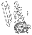
- a pivot tray 100 providing separate splicing and drop connection areas, commonly referred to as closure compartment 102 and terminal compartment 104, respectively, within the enclosure 20.
- closure compartment 102 the pivot tray 100 is shown in the closed or "secured” position
- Fig. 9 the pivot tray 100 is shown oriented in the open or “unsecured” position.
- Craft separation is provided in the enclosure 20 of Figs. 8-9 by providing first compartment 102 (for splicing into the telecommunication lines of the cable) and a second compartment 104 (for establishing drop connections from the splice telecommunication lines).
- the pivot tray 100 separates and defines the first and second compartments 102, 104 on opposite sides of the pivot tray 100, such that first compartment 102 is adjacent a back side 106 of the pivot tray 100 and second compartment 104 is adjacent a front side 108 of the pivot tray 100.
- the back side 106 of the pivot tray 100 is that side facing toward the support basket 50
- the front side 108 of the pivot tray 100 is that side facing away from the support basket 50.
- the first compartment 102 is only accessible when the pivot tray 100 is moved (e.g., by pivoting) into the open or unsecured position as shown in Fig. 9
- the second compartment is accessible simply by opening the enclosure, as by removing the housing 24 from the base 22.
- the pivot tray 100 is pivotably mounted to the support basket 50 in a similar manner as adaptor bracket 82 described above.
- the pivot tray 100 includes lateral protrusions 110 near its bottom edge.
- the lateral protrusions 110 are configured to engage opposed openings 86 in the support basket 50 near the bottom of the support basket 50, such that the pivot tray 100 pivots or rotates about the axis defined by the lateral protrusions 110 near the bottom of the support basket 50.
- the top end 112 of the pivot tray 100 is configured to be secured to the top 53 of the support basket 50, such as by a retaining screw and/or a security wire, to maintain pivot tray 100 in the closed or secured position and prevent unauthorized access to the closure compartment 102.
- the pivot tray 100 includes connector mounting features 114 positioned on its front side 108, and splice forming, organization and management features 116 positioned on its back side.
- the top portion of the front side 108 of pivot tray 100 is raised to form a routing compartment 118 and mounting face 120 for standard connector couplings 122, such as SC connector couplings.
- the routing compartment 118 is configured to comply with bend radius requirements of optical fibers.
- Mounting face 120 may be angled relative to front side 108 to ease engagement and disengagement of connector couplings 122 and maximize space for the connector and its strain relief boot.
- a splice tray 124 is mounted on or integrally formed with the back side 106 of the pivot tray 100. Positioning the splice tray 124 on the back side 106 of the pivot tray 100 (instead of mounting the splice tray on the support tabs 70 of support basket 50, as shown and describe with respect to Figs. 2-4 ) helps for easy routing of the connector pigtails from the splice tray 124 to the connector couplings 122 located in mounting face 120 on the front side 108 of the pivot tray 100. In addition, storage space 76 for slack telecommunication lines remains between the splice tray 124 on the back side 106 of the pivot tray 100 and the support basket 50 when pivot tray 100 is in the closed or secured position.
- Some drop cables may have pre-terminated pigtail connectors that can simply be plugged into the connector couplings 122 mounted onto the front (terminal compartment) side 108 of the pivot tray 100.
- Other drop cables may require a fusion or mechanical splice be formed between a pigtail connector fiber and the drop cable fibers. In this case, slack lengths of the pigtail connector fibers can be stored and managed on the flat front side 108 of the pivot tray 100.
- a splice tray or splice holders can be mounted on or integrally formed with the front side 108 of the pivot tray 100 to allow splicing of the drop cable fibers to the pigtail fibers in the second (terminal) compartment.
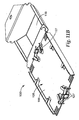
- a pivot tray 100' includes a fiber management tray 126 having fiber retention structures 127 integrally formed on one of or both back side 106 and front side 108. Fiber retention structures 127 are configured for management and storage of telecommunication lines and elements thereof (e.g., holding loops of optical fiber and/or splice holders of the types known in the art). Fiber management tray 126 may also be configured to accept and retain one or more splice trays (not shown) of the types known in the art.
- optical components e.g., 1xN or 2xN power splitters, WDM, CDWM, DWDM, switches, etc.
- a splice tray 124 Figures 3-7 and 9
- fiber management trays 126 Figures 11A and 11B
- directly mounted on back side 102 of pivot tray 100 or directly mounted on the support basket 50 or in the first compartment 76 area using any suitable mounting means according to the application requirement.
- pivot tray 100 is formed with multiple rows of the couplings 122 to form a fiber distribution patch panel on front side 108 of pivot tray 100, and optical components can be mounted as described above on the back side 106 of pivot tray 100 to support fiber distribution point applications.
- a pigtail connection is made with the telecommunication line in the enclosure and routed to an external connector (e.g. an OptitapTM connector made by Coming) positioned in a port 26 of the base 22, thereby allowing drop connection without further opening of the enclosure 20.
- an external connector e.g. an OptitapTM connector made by Coming
- the pivot tray 100 beneficially allows any enclosure 20 initially having only a single compartment to be converted to an enclosure 20 having separate closure and termination compartments 102, 104, respectively, where such separate compartments are necessary or desirable.
- the pivot tray 100 is illustrated with a particular support basket 50 having a support band 52, use of the pivot tray 100 is not so limited.
- the pivot tray 100 may be installed in any suitable enclosure 20, with or without a support basket 50. Where a support basket 50 is used, the configuration of the support basket 50 may be adapted to the particular size and shape of the enclosure 20, and use of a support band 52 as described herein is not required.
- pivot tray 100 may be used with a support basket 50 similar to that illustrated, but without the support band 52. Where deflection of the housing 24 is a concern, the support band 52 can be used.
- the pivot tray 100 may be pivotably mounted directly to the enclosure 20, without using a support basket 50.
- the various components of the enclosure 20, support frame 40, and elements thereof are formed of any suitable material.
- the materials are selected depending upon the intended application and may include both polymers and metals.
- the base 22 and housing 24 are formed of polymeric materials by methods such as injection molding, extrusion, casting, machining, and the like, while the support frame 40 and components thereof are formed of metal by methods such as molding, casting, stamping, machining the like. Material selection will depend upon factors including, but not limited to, chemical exposure conditions; environmental exposure conditions including temperature and humidity conditions, flame-retardancy requirements, material strength, and rigidity, to name a few.
- enclosure 20, support frame 40, pivot tray 100 and components thereof can be used and adapted to many diverse applications, including (but not limited to) telecommunication cables, electrical power cables, optical fiber cables, copper wire cables, drop lines, branch lines, distribution lines, pipes and conduits, to name a few.
Description
- The present invention relates generally to enclosures for telecommunications cables. More particularly, the invention relates to enclosures for containing telecommunication lines and telecommunication line splices.
- Telecommunication cables are ubiquitous and used for distributing all manner of data across vast networks. The majority of cables are electrically conductive cables (typically copper), although the use of optical fiber cables is growing rapidly in telecommunication systems as larger and larger amounts of data are transmitted. A telecommunication cable typically includes a bundle of individual telecommunication lines (either optical fibers or copper wires) that are encased within a protective sheath. As telecommunication cables are routed across data networks, it is necessary to periodically open the cable so that one or more telecommunication lines therein may be spliced, thereby allowing data to be distributed to other cables or "branches" of the telecommunication network. The cable branches may be further distributed until the network reaches individual homes, businesses, offices, and so on.
- At each point where a telecommunication cable is opened, it is necessary to provide some type of enclosure to protect the exposed interior of the cable. Commonly, the enclosure has one or more ports through which cables enter and/or exit the enclosure. Once inside the enclosure, the cable is opened to expose the telecommunication lines therein. Conventional telecommunication enclosures are constructed to facilitate the management and protection of individual telecommunication lines and splices thereof. For example, conventional enclosures have re-enterable housings and are designed to incorporate splice trays to assist a craftsman in creating a splice connection between two telecommunication lines. Once all required splices are made, the enclosure is secured to protect the opened portion of the cable from moisture, dust, insects, and other hazards.
- After an enclosure is closed and secured, it must satisfy several technical performance requirements to ensure reliable protection of the opened portion of the cable and various other electronic or optical components within the enclosure. For example, the enclosure must satisfy various environmental related requirements, such as corrosion and insect resistance, and must be able to withstand predetermined external pressures and impact forces without failing. Polymer enclosures are generally preferred, as they most easily satisfy the environmental requirements, in addition to being more easily produced. However, polymer materials often have more difficulty satisfying the pressure and impact requirements. According to current performance requirements such as Telcodia GR771, enclosures for some applications (such as hand-hole installations) must be capable of withstanding an external pressure equivalent to a 20 ft. (6.1 m) water-head and an impact force of 100 ft-lbs (13.84 kg-m) without leaking, collapsing, cracking, or otherwise failing. These particular performance requirements are somewhat conflicting, because a rigid enclosure is preferred for satisfying the pressure testing requirement, while a resilient enclosure is preferred for satisfying the impact testing requirement. As a result, enclosures having sufficient rigidity to withstand the external pressure requirements are often so rigid as to crack or shatter when subjected to the impact requirements, while enclosures having sufficient resiliency to withstand the impact requirements often incur substantial deflection that can cause damage to internal components when subjected to the impact and external pressure requirement. Document
US 6533472 discloses such an enclosure known from the prior art. - In one embodiment, the enclosure comprises a housing longitudinally extending from an open first end to a closed second end. The housing defines an internal cavity extending in the longitudinal direction, the internal cavity having a circumferential shape in a direction transverse to the longitudinal direction. A base member is configured for attachment to the open first end of the housing to provide an enclosed configuration. The base member defines at least one port configured for passage of at least one telecommunications cable therethrough. A support basket is connected to the base member, wherein the support basket extends longitudinally within the internal cavity of the housing in the enclosed configuration. The support basket is shaped to substantially conform to the circumferential shape of the internal cavity. A pivot tray is pivotably mounted to the support basket, wherein the pivot tray defines a closure compartment between a first side of the pivot tray and the support basket and a terminal compartment on a second side of the pivot tray opposite the closure compartment.
- Embodiments of the invention are better understood with reference to the following drawings. The elements of the drawings are not necessarily to scale relative to each other. Like reference numerals designate corresponding similar parts.
-
Figure 1 is an exploded perspective illustration of one embodiment of an enclosure having a support frame according to the invention. -
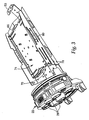
Figure 2 is a perspective illustration showing the support frame ofFig. 1 attached to a base of the enclosure. -
Figure 3 is a perspective illustration of the support frame and base ofFig. 2 showing splice trays being stacked. -
Figure 4 is a perspective illustration of the support frame and base ofFig. 3 showing the support frame filled with splice trays. -
Figure 5 is a perspective illustration showing a bracket for adapting the support frame ofFigs. 1-2 for use with hinged splice trays. -
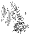
Figure 6 is a perspective illustration showing the adaptor bracket ofFig. 5 installed in the support frame ofFig. 2 and receiving a plurality of hinged splice trays. -
Figure 7 is a perspective illustration showing the hinged splice trays ofFig. 6 assembled in the support frame. -
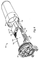
Figure 8 is a perspective illustration of the enclosure and support frame ofFigs. 1-2 used with a pivot tray dividing the enclosure into separate closure and termination compartments. -
Figure 9 is a perspective illustration of the enclosure ofFig. 8 , showing the pivot tray positioned to allow access to the closure compartment. -
Figure 10 is a perspective illustration of an alternate support band configuration. -
Figures 11A and11B are perspective illustrations of a dual-sided splice tray usable in the enclosure ofFigures 8 and9 . - In the following detailed description of the preferred embodiments, reference is made to the accompanying drawings, which form a part hereof, and in which is shown by way of illustration specific embodiments in which the invention may be practiced. The illustrated embodiments are not intended to be exhaustive of all embodiments according to the invention. It is to be understood that other embodiments may be utilized and structural or logical changes may be made without departing from the scope of the present invention. The following detailed description, therefore, is not to be taken in a limiting sense, and the scope of the present invention is defined by the appended claims.
- For purposes of clarity, the invention is described herein as used with telecommunication cables or simply "cables" having one or more telecommunication lines therein. However, such use is exemplary only, and it is understood and intended that the present invention is equally suitable for use with other types of cables including, but not limited to, electrical power cables, optical fiber cables, copper wire cables, coaxial cables, drop lines, branch lines, and distribution lines, to name a few. Similarly, the invention is described herein as used with telecommunication line splices, or simply "splices". However, such use is exemplary only, and it is understood and intended that the present invention is equally suitable for use with other types of interconnections including, but not limited to, splices, connectors, hybrid connectors, and optical or electrical components as are known in the art, to name a few.
- Referring to
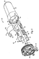
Figs. 1 and2 , anexemplary enclosure 20 according to one embodiment of the invention is illustrated in an exploded or disassembled condition. Theenclosure 20 includes abase 22 and ahousing 24 removeably securable to thebase 22. Thebase 22 includes at least oneport 26 for receiving a telecommunications cable (not shown). Theports 26 allow passage of a single cable, or multiple cables in combination with a sealing member as is known in the art. Thebase 22 may have one, two, or anyother number ports 26 as is required for aparticular enclosure 20. Thehousing 24 is hollow and defines a longitudinalinternal cavity 30 extending from afirst end 32 to asecond end 34 of thehousing 24. Theinternal cavity 30 has a circumferential shape in a direction transverse to the longitudinal direction. An opening at thefirst end 32 of thehousing 24 is shaped and sized to fit over and engage with thebase 22 in a conventional manner. When engaged, thebase 22 andhousing 24 provide protection for the internal components of theenclosure 20 from weather, insects and other external hazards. - In the exemplary embodiment, the
housing 24 andcavity 30 therein are substantially oval in transverse cross-section, and the closedsecond end 34 of thehousing 24 is substantially dome-shaped. Thebase 22 has a substantially oval cross-section in the transverse direction that matches the shape of the open end of thehousing 24. However, in practice, the shapes of thebase 22 andhousing 24 are not so limited, and in other embodiments thehousing 24 andbase 22 may have other shapes and cross-sections. For example, shape of the transverse cross-section of thehousing 24 andbase 22 may be substantially circular, rectangular, square, or any other shape as is required or desired for a particular application. The closedsecond end 34 of thehousing 24 may likewise be any suitable shape. In other embodiments, the closedsecond end 34 of thehousing 24 is not monolithically formed with the remainder of thehousing 24, as shown in the illustrated embodiment. For example, in other embodiments thehousing 24 may comprise an assembly of components, such as a longitudinal hollow body having two open ends, wherein a cap or other similar device is used to form the closedsecond end 34. In one embodiment, thehousing 24 is made without internal or external rib members, thereby requiring an increase in housing material (e.g., polymer) strength to meet external pressure requirements, at the expense of a compromised ability to satisfy the impact requirements. - A
support frame 40 is secured to thebase 22 by one or moremounting bracket portions 42 extending from theframe 40. The mountingbracket portions 42 in the illustrated embodiment are configured to be secured to thebase 22 by bolts or screws (not shown). In other embodiments, thesupport frame 40 may be secured to thebase 22 by any conventional means including, but not limited to bolts, screws, interlocking elements on theframe 40 andbase 22, adhesive, or any other suitable means. Thesupport frame 40 is shaped to extend longitudinally into theinternal cavity 30 of thehousing 24 when theenclosure 20 is closed. Thesupport frame 40 includes at least oneportion 44 that provides support about substantially the entire circumference of theinternal cavity 30 ofhousing 24 at between thefirst end 32 and thesecond end 34 of thehousing 24 to prevent excessive deflection or collapse of thehousing 24 under excessive force or pressure. In one embodiment, thesupport frame 40, and inparticular portion 44, is configured to be in contact with thewalls 46 of theinternal cavity 30 to minimize deflection of thehousing 24. In another embodiment, thesupport frame 40, and inparticular portion 44, is spaced from thewalls 46 of theinterior cavity 30 to provide clearance for installation of the housing over thesupport frame 40 and to allow a predetermined amount of deflection of thehousing 24. In one embodiment, thesupport frame 40 is spaced from theinterior walls 46 of thehousing 24 by a distance of about 10% or less of the internal diameter of theinterior cavity 30. For example, for aninternal cavity 30 having an internal diameter of about 8 inches, theframe 40 is spaced from theinterior walls 46 by a distance of about 0.8 inches or less. - In one embodiment, mounting
bracket portions 42 are integrally formed withsupport frame 40, such as by stampingframe 40 and mountingbracket portions 42 from a single piece of sheet metal,molding frame 40 and mountingbracket portions 42 as a single unit, orovermolding frame 40 onto mountingbracket portions 42. In another embodiment, mountingbracket portions 42 are separately formed fromsupport frame 40 and then secured to frame 40 using any suitable conventional means, such as screws, bolts, welding, adhesive, etc. - As illustrated in
Figs. 1 and2 , in one embodiment thesupport frame 40 includes a generallyU-shaped support basket 50 having an exterior surface configured to substantially conform to a first portion of the circumferential shape of theinternal cavity 30, and a generallyU-shaped support band 52 having an exterior surface configured to substantially conform to a second portion of the circumferential shape of thecavity 30. Together, thesupport basket 50 and thesupport band 52 provide support about the circumference of theinternal cavity 30 of thehousing 24 by closely conforming to the circumferential shape of thewalls 46 ofinternal cavity 30. The combinedsupport basket 50 andsupport band 52 reinforces thewalls 46 and provides resistance and limits the deflection of thehousing 24 under heavy external pressure, such as caused by water or ice. It also deflects and absorbs impact forces protecting the telecommunication lines and splices therein. Thesupport basket 50 also protects telecommunication lines therein by preventing accidental pinching of the lines during installation of thehousing 24 on thebase 22. - For purposes of description, the end of the
support basket 50 nearest thebase 22 will be described as being the "bottom" of thesupport basket 50, while the end of thesupport basket 50 furthest from the base 22 will be described as being the "top" of thesupport basket 50. In the illustrated implementation, thesupport band 52 is positioned such that it supports thehousing 24 near a midpoint along the length of thesupport basket 50. In other embodiments, thesupport band 52 is positioned closer to the bottom of thesupport basket 50 or closer to the top of thesupport basket 50, depending upon the portion of thehousing 24 containing critical telecommunication lines and components that are desired to be protected under external pressure and impact forces. In the illustrated implementation, thesupport band 52 extends longitudinally along theinternal cavity 30 for only a portion of the length of thesupport basket 50. In other embodiments, thesupport band 52 may extend longitudinally along up to the full length of thesupport basket 50. In one embodiment, the top 53 of thesupport basket 50 may be configured to conform to the shape of the closedsecond end 34 of thehousing 24, and so as to aid in containing and protecting telecommunication lines during installation and removal of thehousing 24 from thebase 22. - The
support basket 50 is configured to manage and protect telecommunication lines and splices therein. In one embodiment, thesupport basket 50 extends substantially the full length of theinternal cavity 30 of thehousing 24. In other embodiments, thesupport basket 50 does not extend the full length of theinternal cavity 30. In one embodiment, thesupport basket 50 conforms to about one half of the circumference of theinternal cavity 30. In other embodiments, thesupport basket 50 conforms to more than about one half of the circumference of theinternal cavity 30. In other embodiments, thesupport basket 50 conforms to less than about one half of the circumference of theinternal cavity 30. Although only asingle support band 52 is illustrated, more than onesupport band 52 may be secured to thesupport basket 50. - The
support band 52 may be secured to thesupport basket 50 using conventional techniques. In one embodiment, thesupport band 52 is releasably secured to thesupport basket 50, so as to provide full and easy access to the interior of thesupport basket 50. For example, in the exemplary embodiment thesupport basket 50 includesslots 60 shaped to receivetabs 62 extending from thesupport band 52. Theslots 60 andtabs 62 may optionally be provided with interlocking features to prevent inadvertent disengagement of thesupport basket 50 and thesupport band 52. During installation or when working within theenclosure 20, thesupport band 52 can be removed, and then reinstalled prior to securing theenclosure 20. In other embodiments, thesupport band 52 is permanently secured to thesupport basket 50. In one embodiment,support band 52 is integrally formed withsupport basket 50. In one embodiment, thesupport band 52 is secured to supportbasket 50 by a hinge member, thereby allowing thesupport band 52 to be rotated out of the way when access to the interior of thesupport basket 50 is required. In another embodiment,support band 52 is a separate hoop that slidingly engages and surroundssupport basket 50. Those skilled in the art will recognize other suitable configurations and means for securing thesupport band 52 to thesupport basket 50. - The
support basket 50 is configured to support, maintain and manage telecommunication lines and splices in several different manners, depending upon the requirements of a particular installation. In one implementation, telecommunication lines and splices may simply be positioned within the interior of the generallyU-shaped support basket 50, without any other type of telecommunication line management features (such as splice trays, excess line holders, optical/electrical components etc.). In other implementations, telecommunication line management features are used with and incorporated into thesupport basket 50. For example, the illustratedsupport basket 50 andsupport band 52 may be used with different types of splice trays. In particular, thesupport basket 50 may be used to support stackable trays 66 (Figs. 3-4 ) or hinged trays 68 (Figs. 6-7 ). - Referring to
Figs. 3-4 , thesupport basket 50 is shown usingstackable splice trays 66.Support basket 50 is provided withsupport tabs 70 that protrude into the interior of thesupport basket 50.Support tabs 70 serve as mounting or support points forflat splice trays 66 as are known in the art. In the illustrated embodiment, thesupport tabs 70 are positioned such that a plurality offlat splice trays 66 may be supported in a stacked manner. The number ofsplice trays 66 that can be supported depends on the size of thesupport basket 50 and the size ofsplice trays 66. In the illustrated embodiment, up to four (4)splice trays 66 can be supported (seeFig. 4 ). In one embodiment, holes 72 in thesupport tabs 70 mate with protrusions (not shown) on thesplice trays 66 and serve as locating features for thesplice trays 66 and prevent thetrays 66 from sliding after installation. Thesupport tabs 70 also aid in maintainingseparate splice areas 74 and telecommunication lineslack storage areas 76 within theenclosure 20. In particular, upon installation of asplice tray 66 on thesupport tabs 70, astorage area 76 for excess lengths of telecommunication lines is formed between thesplice tray 66 and the interior surface of thesupport basket 50. Excess lengths of telecommunication lines are thus easily accessible, but simultaneously prevented from interfering with splicing of telecommunication lines on thesplice trays 66. Holes orslots 78 in thesupport basket 50 may be used to secure slack telecommunication line loops with for example, cable ties or other means known in the art. Thesplice trays 66 may be secured to thesupport basket 50 in any conventional manner. In one embodiment,slots 80 on the side of thesupport basket 50 may be used for mounting a strap (not shown) or other securing means which secures thesplice trays 66 to supportbasket 50. In other embodiments, means other than or in addition tosupport tabs 70 may be used or provided to supporttrays 66. For example, mounting brackets (not shown) may be secured to supportbasket 50, where different mounting brackets may be provided with different tray configurations. - Referring now to
Figure 10 , in one embodiment a support band 52' is configured to support, maintain and manage telecommunication lines and splices in a manner similar to supportbasket 50. In the embodiment illustrated inFigure 9 , support band 52' extends substantially the full length ofsupport basket 50, and is configured similarly to supportbasket 50 to include support tabs 70', holes 78' and any other desired features for securing additional splice trays, telecommunication lines, and the like. - Referring now to
Figs. 5-7 , thesupport basket 50 is shown using hingedsplice trays adaptor bracket 82 is installed in thesupport basket 50. Theadaptor bracket 82 provides mounting features for the hinged splice trays 68, and further creates a telecommunication lineslack storage section 76 underneath thebracket 82. Theadaptor bracket 82 may be mounted on thesupport basket 50 using any suitable conventional means, such as screws, interlocking snaps, sliding engagement features, adhesive, etc. - In the illustrated embodiment, the
adaptor bracket 82 is secured to thesupport basket 50 in a hinged manner. Theadaptor bracket 82 includeslateral protrusions 84 near its bottom edge. Thelateral protrusions 84 are configured to engageopposed openings 86 in thesupport basket 50 near the bottom of thesupport basket 50, such thatadaptor bracket 82 may be rotated about the axis defined by thelateral protrusions 84. In one embodiment, at least one ofopenings 86 is provided with aslot 87 to capture a mating one ofprotrusions 84, such that thebracket 50 is held in an open position. In this manner, the slack telecommunicationline storage area 76 under theadaptor bracket 82 may be easily accessed by rotating thebracket 82 and any splice trays 68 thereon out of the way. In addition, during installation and repair, a craftsman can completely remove theadaptor bracket 82 and any installed splice trays 68 to ease the creation of splices. In one embodiment, thetop end 83 of theadaptor bracket 82 is configured to be secured totop end 53 ofsupport basket 50 to prevent unintended rotation of theadaptor bracket 82. In one embodiment, theadaptor bracket 82 andsupport basket 50 may be secured together near the top of thesupport basket 50, such as by a retaining screw and/or a security wire, to prevent unauthorized access to the slack telecommunicationline storage area 76. - In one embodiment, the mounting features of the
adaptor bracket 82 allow more than one type or size of hinged splice tray 68 to be attached to theadaptor bracket 82. For example, theadaptor bracket 82 may be configured to allow mounting of 5 mmthick splice trays 68a and/or 10 mmthick splice trays 68b by selection of anappropriate mounting bracket Fig. 5 , a mountingbracket 90a for four 5 mm thick hingedsplice trays 68a and a mountingbracket 90b for two 10 mm thick hingedsplice trays 68b are shown. Mountingbrackets lateral edges 92 havinggrooves 94 shaped for snap engagement with pivot pins 96 extending from thesplice trays brackets adaptor bracket 82, such that the desired configuration ofsplice trays adaptor bracket 82 can be modified to suit a particular application. In one embodiment, each mountingbracket tab 95 extending from a top end which mounts in acorresponding slot 97 in theadaptor bracket 82 and thereby properly positions the mountingbrackets adaptor bracket 82. A retaining screw (not shown) extending throughholes 98 at a bottom end of the mountingbrackets brackets brackets adaptor bracket 82 using any other suitable means. Beneficially,tabs 99 formed onbracket 82 allow management and securing of telecommunication lines to thebracket 82 before entering into the hinged splice trays. This provides the strain relief and organization of the telecommunication lines. - As telecommunication networks are expanded, two separate craft crews may need to work within the
enclosure 20. First, construction crews (typically having higher levels of skill and training) install theenclosure 20, open the cable to expose the telecommunication lines therein, splice into the telecommunication lines, and make it ready for the final drop connection. At a later time, such as when a customer subscribes to a service, installation and repair crews (typically having lower levels of skill and training) install a final drop connection to the customer premise and turn the service on or off. Because of the differing skill levels between the crafts, it is desirable to provide craft separation to prevent unwanted or unauthorized access (either intentional or inadvertent) to the telecommunication lines and splices thereof to maintain and improve reliability and integrity of the network. - Referring now to
Figs. 8-9 , thesupport basket 50 as described above is shown as used with apivot tray 100 providing separate splicing and drop connection areas, commonly referred to asclosure compartment 102 andterminal compartment 104, respectively, within theenclosure 20. InFig. 8 thepivot tray 100 is shown in the closed or "secured" position, while inFig. 9 thepivot tray 100 is shown oriented in the open or "unsecured" position. Craft separation is provided in theenclosure 20 ofFigs. 8-9 by providing first compartment 102 (for splicing into the telecommunication lines of the cable) and a second compartment 104 (for establishing drop connections from the splice telecommunication lines). In particular, thepivot tray 100 separates and defines the first andsecond compartments pivot tray 100, such thatfirst compartment 102 is adjacent aback side 106 of thepivot tray 100 andsecond compartment 104 is adjacent afront side 108 of thepivot tray 100. For purposes of description, theback side 106 of thepivot tray 100 is that side facing toward thesupport basket 50, while thefront side 108 of thepivot tray 100 is that side facing away from thesupport basket 50. Thefirst compartment 102 is only accessible when thepivot tray 100 is moved (e.g., by pivoting) into the open or unsecured position as shown inFig. 9 , while the second compartment is accessible simply by opening the enclosure, as by removing thehousing 24 from thebase 22. - The
pivot tray 100 is pivotably mounted to thesupport basket 50 in a similar manner asadaptor bracket 82 described above. In particular, thepivot tray 100 includeslateral protrusions 110 near its bottom edge. Thelateral protrusions 110 are configured to engageopposed openings 86 in thesupport basket 50 near the bottom of thesupport basket 50, such that thepivot tray 100 pivots or rotates about the axis defined by thelateral protrusions 110 near the bottom of thesupport basket 50. Thetop end 112 of thepivot tray 100 is configured to be secured to the top 53 of thesupport basket 50, such as by a retaining screw and/or a security wire, to maintainpivot tray 100 in the closed or secured position and prevent unauthorized access to theclosure compartment 102. - The
pivot tray 100 includesconnector mounting features 114 positioned on itsfront side 108, and splice forming, organization and management features 116 positioned on its back side. Referring toFig. 8 , the top portion of thefront side 108 ofpivot tray 100 is raised to form arouting compartment 118 and mountingface 120 forstandard connector couplings 122, such as SC connector couplings. In one embodiment, therouting compartment 118 is configured to comply with bend radius requirements of optical fibers. Mountingface 120 may be angled relative tofront side 108 to ease engagement and disengagement ofconnector couplings 122 and maximize space for the connector and its strain relief boot. - Referring to
Fig. 9 , asplice tray 124 is mounted on or integrally formed with theback side 106 of thepivot tray 100. Positioning thesplice tray 124 on theback side 106 of the pivot tray 100 (instead of mounting the splice tray on thesupport tabs 70 ofsupport basket 50, as shown and describe with respect toFigs. 2-4 ) helps for easy routing of the connector pigtails from thesplice tray 124 to theconnector couplings 122 located in mountingface 120 on thefront side 108 of thepivot tray 100. In addition,storage space 76 for slack telecommunication lines remains between thesplice tray 124 on theback side 106 of thepivot tray 100 and thesupport basket 50 whenpivot tray 100 is in the closed or secured position. - When establishing drop lines from the
enclosure 20, several types of connections may be accommodated. Some drop cables may have pre-terminated pigtail connectors that can simply be plugged into theconnector couplings 122 mounted onto the front (terminal compartment)side 108 of thepivot tray 100. Other drop cables may require a fusion or mechanical splice be formed between a pigtail connector fiber and the drop cable fibers. In this case, slack lengths of the pigtail connector fibers can be stored and managed on the flatfront side 108 of thepivot tray 100. In one embodiment, a splice tray or splice holders can be mounted on or integrally formed with thefront side 108 of thepivot tray 100 to allow splicing of the drop cable fibers to the pigtail fibers in the second (terminal) compartment. In one embodiment, as shown inFigures 11A and11B , apivot tray 100' includes afiber management tray 126 havingfiber retention structures 127 integrally formed on one of or bothback side 106 andfront side 108.Fiber retention structures 127 are configured for management and storage of telecommunication lines and elements thereof (e.g., holding loops of optical fiber and/or splice holders of the types known in the art).Fiber management tray 126 may also be configured to accept and retain one or more splice trays (not shown) of the types known in the art. - In one embodiment, optical components (e.g., 1xN or 2xN power splitters, WDM, CDWM, DWDM, switches, etc.) can be mounted in a splice tray 124 (
Figures 3-7 and9 ), held by fiber management trays 126 (Figures 11A and11B ), directly mounted onback side 102 ofpivot tray 100, or directly mounted on thesupport basket 50 or in thefirst compartment 76 area using any suitable mounting means according to the application requirement. - In one embodiment,
pivot tray 100 is formed with multiple rows of thecouplings 122 to form a fiber distribution patch panel onfront side 108 ofpivot tray 100, and optical components can be mounted as described above on theback side 106 ofpivot tray 100 to support fiber distribution point applications. - In other embodiments, a pigtail connection is made with the telecommunication line in the enclosure and routed to an external connector (e.g. an Optitap™ connector made by Coming) positioned in a
port 26 of thebase 22, thereby allowing drop connection without further opening of theenclosure 20. - The
pivot tray 100 beneficially allows anyenclosure 20 initially having only a single compartment to be converted to anenclosure 20 having separate closure andtermination compartments pivot tray 100 is illustrated with aparticular support basket 50 having asupport band 52, use of thepivot tray 100 is not so limited. In particular, thepivot tray 100 may be installed in anysuitable enclosure 20, with or without asupport basket 50. Where asupport basket 50 is used, the configuration of thesupport basket 50 may be adapted to the particular size and shape of theenclosure 20, and use of asupport band 52 as described herein is not required. For example, where deflection of thehousing 24 is not a concern,pivot tray 100 may be used with asupport basket 50 similar to that illustrated, but without thesupport band 52. Where deflection of thehousing 24 is a concern, thesupport band 52 can be used. In other implementations, thepivot tray 100 may be pivotably mounted directly to theenclosure 20, without using asupport basket 50. - In each of the embodiments and implementations described herein, the various components of the
enclosure 20,support frame 40, and elements thereof are formed of any suitable material. The materials are selected depending upon the intended application and may include both polymers and metals. In one embodiment, thebase 22 andhousing 24 are formed of polymeric materials by methods such as injection molding, extrusion, casting, machining, and the like, while thesupport frame 40 and components thereof are formed of metal by methods such as molding, casting, stamping, machining the like. Material selection will depend upon factors including, but not limited to, chemical exposure conditions; environmental exposure conditions including temperature and humidity conditions, flame-retardancy requirements, material strength, and rigidity, to name a few. - Although described herein generally with respect to telecommunication cables, telecommunication lines, and telecommunication line splices, it is within the scope of the invention that the
enclosure 20,support frame 40,pivot tray 100 and components thereof can be used and adapted to many diverse applications, including (but not limited to) telecommunication cables, electrical power cables, optical fiber cables, copper wire cables, drop lines, branch lines, distribution lines, pipes and conduits, to name a few. - Although specific embodiments have been illustrated and described herein for purposes of description of the preferred embodiment, it will be appreciated by those of ordinary skill in the art that a wide variety of alternate or equivalent implementations may be substituted for the specific embodiments shown and described without departing from the scope of the present invention. Those with skill in the art will readily appreciate that the present invention may be implemented in a very wide variety of embodiments. This application is intended to cover any adaptations or variations of the embodiments discussed herein. Therefore, it is manifestly intended that this invention be limited only by the claims and the equivalents thereof.
Claims (3)
- An enclosure (20) comprising:- a housing (24) longitudinally extending from an open first end to a closed second end, the housing defining an internal cavity (30) extending in the longitudinal direction, the internal cavity having a circumferential shape in a direction transverse to the longitudinal direction;- a base member (22) configured for attachment to the open first end of the housing to provide an enclosed configuration, the base member (22) defining at least one port (26) configured for passage of at least one telecommunications cable therethrough;- a support basket (50) connected to the base member (22), wherein the support basket extends longitudinally within the internal cavity of the housing in the enclosed configuration, the support basket shaped to substantially conform to the circumferential shape of the internal cavity;- a pivot tray (66) pivotably mounted to the support basket, wherein the pivot tray defines a closure compartment between a first side of the pivot tray and the support basket and a terminal compartment on a second side of the pivot tray opposite the closure compartment, characterized in that the enclosure further comprisesa support band (52) secured to the support basket, the support band shaped to substantially conform to the circumferential shape of the cavity, wherein the support basket and the connected support band extend around substantially the entire circumference of the internal cavity
- The enclosure of claim 1, wherein the pivot tray is lockable to the support basket to control access to the closure compartment.
- The enclosure of claim 1, wherein the pivot tray comprises a splice tray on the first side of the pivot tray and connector mounting features on the second side of the pivot tray.
Applications Claiming Priority (2)
| Application Number | Priority Date | Filing Date | Title |
|---|---|---|---|
| US11/216,229 US7333706B2 (en) | 2005-08-31 | 2005-08-31 | Enclosure and organizer for telecommunication lines and splices |
| PCT/US2006/031102 WO2007027388A2 (en) | 2005-08-31 | 2006-08-09 | Enclosure and organizer for telecommunication lines and splices |
Publications (2)
| Publication Number | Publication Date |
|---|---|
| EP1929346A2 EP1929346A2 (en) | 2008-06-11 |
| EP1929346B1 true EP1929346B1 (en) | 2013-02-27 |
Family
ID=37307166
Family Applications (1)
| Application Number | Title | Priority Date | Filing Date |
|---|---|---|---|
| EP06789634A Not-in-force EP1929346B1 (en) | 2005-08-31 | 2006-08-09 | Enclosure and organizer for telecommunication lines and splices |
Country Status (10)
| Country | Link |
|---|---|
| US (1) | US7333706B2 (en) |
| EP (1) | EP1929346B1 (en) |
| JP (1) | JP2009506380A (en) |
| CN (1) | CN101263409B (en) |
| AR (1) | AR054951A1 (en) |
| BR (1) | BRPI0615308A2 (en) |
| MX (1) | MX2008002430A (en) |
| RU (1) | RU2372699C1 (en) |
| TW (1) | TW200717958A (en) |
| WO (1) | WO2007027388A2 (en) |
Families Citing this family (40)
| Publication number | Priority date | Publication date | Assignee | Title |
|---|---|---|---|---|
| US7120347B2 (en) * | 2004-01-27 | 2006-10-10 | Corning Cable Systems Llc | Multi-port optical connection terminal |
| US7509015B2 (en) * | 2006-07-26 | 2009-03-24 | Ortronics, Inc. | Secure fiber optic network cassette assembly |
| US7668432B2 (en) * | 2007-01-31 | 2010-02-23 | Tyco Electronics Corporation | Multi-drop closure systems and methods for fiber optic cabling |
| US7499622B2 (en) * | 2007-02-28 | 2009-03-03 | Corning Cable Systems Llc | Fiber optic drop terminals for multiple dwelling units |
| US7740409B2 (en) * | 2007-09-19 | 2010-06-22 | Corning Cable Systems Llc | Multi-port optical connection terminal |
| US7697812B2 (en) * | 2008-01-18 | 2010-04-13 | 3M Innovative Properties Company | Enclosure and organizer for telecommunication lines and splices |
| CN101521545B (en) * | 2008-02-27 | 2012-10-10 | 3M创新有限公司 | High-density optical fiber distributing hub |
| US7580608B1 (en) | 2008-04-29 | 2009-08-25 | Corning Cable Systems Llc | Pushing-in fiber optic cable driver |
| US8554042B2 (en) * | 2009-02-18 | 2013-10-08 | Commscope, Inc. | Optical fiber management shelf including door with push-push fastener |
| CA2755337C (en) * | 2009-07-21 | 2015-12-15 | Afl Telecommunications Llc | Modular resealable high conductor count packaging and method |
| CA2756296C (en) * | 2009-10-14 | 2019-09-03 | Afl Telecommunications Llc | Fiber splice enclosure |
| DE102010006611B4 (en) * | 2010-02-01 | 2012-11-08 | Adc Gmbh | Holder for at least one cassette |
| PT2619617T (en) | 2010-09-21 | 2017-03-27 | Huber+Suhner Ag | Environmentally sealed cable breakout assemblies |
| EP2633354A1 (en) | 2010-10-28 | 2013-09-04 | Corning Cable Systems LLC | Impact resistant fiber optic enclosures and related methods |
| US8861919B2 (en) | 2011-02-16 | 2014-10-14 | Tyco Electronics Corporation | Fiber optic closure |
| US9069151B2 (en) | 2011-10-26 | 2015-06-30 | Corning Cable Systems Llc | Composite cable breakout assembly |
| KR101285448B1 (en) * | 2012-01-03 | 2013-07-12 | 에쓰이에이치에프코리아 (주) | Branching device for hybrid fanout cable |
| ES2891094T3 (en) * | 2012-04-03 | 2022-01-26 | CommScope Connectivity Belgium BVBA | Telecom Box & Organizer |
| US8873926B2 (en) | 2012-04-26 | 2014-10-28 | Corning Cable Systems Llc | Fiber optic enclosures employing clamping assemblies for strain relief of cables, and related assemblies and methods |
| EP3252897B1 (en) * | 2012-07-02 | 2018-12-19 | CommScope Connectivity Belgium BVBA | Re-enterable enclosure |
| EP2936228A1 (en) | 2012-12-19 | 2015-10-28 | Tyco Electronics Raychem BVBA | Distribution device with incrementally added splitters |
| US9660397B2 (en) | 2014-03-24 | 2017-05-23 | Commscope Technologies Llc | Plate for cable connector attachments |
| CN106687841B (en) | 2014-06-17 | 2020-08-14 | 康普连通比利时私人有限公司 | Cable distribution system |
| US10509187B2 (en) * | 2014-09-23 | 2019-12-17 | Ppc Broadband, Inc. | Universal multi-purpose compartmentalized telecommunications box |
| RU2583998C1 (en) * | 2015-01-20 | 2016-05-20 | Борис Алексеевич Хозяинов | Device for installation of switching cords in telecommunication rack (box) |
| US10247899B2 (en) * | 2015-09-04 | 2019-04-02 | Commscope Technologies Llc | Device for distributing hybrid trunk cable |
| BR102015023980B1 (en) * | 2015-09-17 | 2022-07-19 | Furukawa Electric Latam S.A. | OPTICAL TERMINATION BOX |
| US10606009B2 (en) | 2015-12-01 | 2020-03-31 | CommScope Connectivity Belgium BVBA | Cable distribution system with fan out devices |
| WO2017129815A1 (en) * | 2016-01-28 | 2017-08-03 | CommScope Connectivity Belgium BVBA | Modular hybrid closure |
| DE202017101492U1 (en) * | 2017-03-15 | 2018-06-26 | Wieland Electric Gmbh | connection adapter |
| US9829665B1 (en) | 2017-04-27 | 2017-11-28 | Afl Telecommunications Llc | Fiber optic splice enclosures |
| EP3698192A4 (en) * | 2017-10-17 | 2021-09-22 | Corning Research And Development Corporation | Enclosure for splicing of optical fibers |
| US10928274B2 (en) * | 2018-03-09 | 2021-02-23 | Viavi Solutions Inc. | Fiber-optic interconnection stabilization apparatus |
| US10558007B2 (en) | 2018-03-13 | 2020-02-11 | Corning Research & Development Corporation | Enclosure for local convergence point for fiber optic communications network |
| ES2928209T3 (en) | 2018-05-14 | 2022-11-16 | Afl Telecommunications Llc | Butt closures and organizer sets therefor |
| US11125961B2 (en) * | 2018-09-07 | 2021-09-21 | Go!Foton Holdings, Inc. | Optical fiber distribution system |
| GB2585377B (en) * | 2019-07-05 | 2023-09-06 | British Telecomm | Protective Apparatus |
| EP3994512A1 (en) * | 2019-07-05 | 2022-05-11 | British Telecommunications public limited company | Protective apparatus |
| DE102019125763A1 (en) * | 2019-09-25 | 2021-03-25 | Connect Com GmbH | Distribution device with channel bodies for sealing devices |
| EP4042219B1 (en) * | 2019-10-08 | 2023-12-06 | AFL Telecommunications LLC | Organizer assemblies for fiber optic closures |
Family Cites Families (28)
| Publication number | Priority date | Publication date | Assignee | Title |
|---|---|---|---|---|
| GB2225442B (en) | 1988-11-26 | 1992-10-14 | Bowthorpe Hellermann Ltd | Optical fibre jointing |
| US5093885A (en) * | 1990-07-11 | 1992-03-03 | Adc Telecommunications, Inc. | Fiber optic connector module |
| US5097529A (en) | 1991-03-22 | 1992-03-17 | At&T Bell Laboratories | Space-saving optical fiber cable closure |
| DE4229884C2 (en) | 1992-09-04 | 1994-06-16 | Krone Ag | Device for storing the single and loose tubes of fiber optic cables in distribution facilities for telecommunications and data technology |
| KR960705231A (en) * | 1993-09-10 | 1996-10-09 | 데이비드 어니스트 오스본 | BREAK-OUT TRAY |
| US5790739A (en) | 1995-12-21 | 1998-08-04 | Siecor Corporation | Optical fiber interconnect and canister closure assembly |
| PL182960B1 (en) | 1996-02-29 | 2002-05-31 | Raychem Sa Nv | Optical fibres distributing apparatus |
| US5734776A (en) * | 1996-08-28 | 1998-03-31 | Adc Telecommunications, Inc. | Outside plant cross-connect apparatus |
| US5774618A (en) | 1996-12-19 | 1998-06-30 | Lucent Technologies Inc. | Compact closure for optical fiber cable |
| US5946440A (en) * | 1997-11-17 | 1999-08-31 | Adc Telecommunications, Inc. | Optical fiber cable management device |
| JPH11167029A (en) | 1997-12-05 | 1999-06-22 | Fujikura Ltd | Extra length housing tray |
| US6014490A (en) | 1998-06-05 | 2000-01-11 | Siecor Operation, Llc | Optical fiber interconnection closure having a fiber management frame |
| US6249632B1 (en) * | 1998-11-12 | 2001-06-19 | Wittmeier, Ii David Arthur | Fiber optic splice closure including end pivoting slack storage holder and associated methods |
| US6249633B1 (en) * | 1998-11-12 | 2001-06-19 | Wittmeier, Ii David Arthur | Fiber optic splice closure including side pivoting slack storage holder and associated methods |
| US6424781B1 (en) * | 1999-03-01 | 2002-07-23 | Adc Telecommunications, Inc. | Optical fiber distribution frame with pivoting connector panels |
| US6507691B1 (en) | 1999-03-22 | 2003-01-14 | Tyco Electronics Corporation | Fiber optic splice organizer with splicing tray and associated method |
| US6275640B1 (en) | 1999-04-21 | 2001-08-14 | Tyco Electrtonics Corporation | Fiber optic splice closure including end pivoting slack storage holder with adjustable rear wall and associated methods |
| US6411767B1 (en) | 1999-08-24 | 2002-06-25 | Corning Cable Systems Llc | Optical fiber interconnection closures |
| US6533472B1 (en) | 1999-10-19 | 2003-03-18 | Alcoa Fujikura Limited | Optical fiber splice closure assembly |
| US6496640B1 (en) | 1999-12-16 | 2002-12-17 | Corning Cable Systems Llc | Splice closure with removable and pivotable splice trays, and associated methods |
| US6539160B2 (en) | 2000-10-27 | 2003-03-25 | Corning Cable Systems Llc | Optical fiber splicing and connecting assembly with coupler cassette |
| US6434313B1 (en) | 2000-10-31 | 2002-08-13 | Corning Cable Systems Llc | Fiber optic closure with couplers and splice tray |
| GB0108255D0 (en) | 2001-04-02 | 2001-05-23 | Tyco Electronics Raychem Nv | Optical fibre organiser |
| BRPI0209987B1 (en) | 2001-05-25 | 2015-04-22 | Preformed Line Products Co | Cable splice apparatus |
| US6621975B2 (en) | 2001-11-30 | 2003-09-16 | Corning Cable Systems Llc | Distribution terminal for network access point |
| US6778752B2 (en) | 2002-05-31 | 2004-08-17 | Corning Cable Systems Llc | Below grade closure for local convergence point |
| US7142764B2 (en) * | 2003-03-20 | 2006-11-28 | Tyco Electronics Corporation | Optical fiber interconnect cabinets, termination modules and fiber connectivity management for the same |
| US7038137B2 (en) | 2003-06-18 | 2006-05-02 | Preformed Line Products Company | Fiber closure system |
-
2005
- 2005-08-31 US US11/216,229 patent/US7333706B2/en active Active
-
2006
- 2006-08-09 RU RU2008113163/09A patent/RU2372699C1/en not_active IP Right Cessation
- 2006-08-09 WO PCT/US2006/031102 patent/WO2007027388A2/en active Application Filing
- 2006-08-09 JP JP2008529060A patent/JP2009506380A/en not_active Withdrawn
- 2006-08-09 MX MX2008002430A patent/MX2008002430A/en active IP Right Grant
- 2006-08-09 CN CN2006800335032A patent/CN101263409B/en not_active Expired - Fee Related
- 2006-08-09 BR BRPI0615308-9A patent/BRPI0615308A2/en not_active IP Right Cessation
- 2006-08-09 EP EP06789634A patent/EP1929346B1/en not_active Not-in-force
- 2006-08-25 TW TW095131251A patent/TW200717958A/en unknown
- 2006-08-30 AR ARP060103777A patent/AR054951A1/en unknown
Also Published As
| Publication number | Publication date |
|---|---|
| WO2007027388A3 (en) | 2007-05-03 |
| CN101263409A (en) | 2008-09-10 |
| MX2008002430A (en) | 2008-03-27 |
| JP2009506380A (en) | 2009-02-12 |
| WO2007027388A2 (en) | 2007-03-08 |
| AR054951A1 (en) | 2007-07-25 |
| EP1929346A2 (en) | 2008-06-11 |
| CN101263409B (en) | 2010-09-01 |
| TW200717958A (en) | 2007-05-01 |
| US7333706B2 (en) | 2008-02-19 |
| RU2372699C1 (en) | 2009-11-10 |
| US20070047895A1 (en) | 2007-03-01 |
| BRPI0615308A2 (en) | 2011-05-17 |
Similar Documents
| Publication | Publication Date | Title |
|---|---|---|
| EP1929346B1 (en) | Enclosure and organizer for telecommunication lines and splices | |
| EP1929347B1 (en) | Enclosure for telecommunication lines and splices | |
| US7697812B2 (en) | Enclosure and organizer for telecommunication lines and splices | |
| EP2508928B1 (en) | Enclosure for telecommunications cables, with removable organizer | |
| EP2185961B1 (en) | Fiber optic cable control clips and enclosure assemblies and methods incorporating the same | |
| US5734776A (en) | Outside plant cross-connect apparatus | |
| CA2750171C (en) | A system for an internal rotating storage spool combined with top and bottom cable access in a fiber distribution terminal | |
| EP2074458B1 (en) | Fiber circuit management system with splice tray | |
| EP3631548A1 (en) | Mechanical cable entry port | |
| WO2014035611A1 (en) | Sealed fiber optic splice tray |
Legal Events
| Date | Code | Title | Description |
|---|---|---|---|
| PUAI | Public reference made under article 153(3) epc to a published international application that has entered the european phase |
Free format text: ORIGINAL CODE: 0009012 |
|
| 17P | Request for examination filed |
Effective date: 20080317 |
|
| AK | Designated contracting states |
Kind code of ref document: A2 Designated state(s): AT BE BG CH CY CZ DE DK EE ES FI FR GB GR HU IE IS IT LI LT LU LV MC NL PL PT RO SE SI SK TR |
|
| 17Q | First examination report despatched |
Effective date: 20100805 |
|
| DAX | Request for extension of the european patent (deleted) | ||
| GRAP | Despatch of communication of intention to grant a patent |
Free format text: ORIGINAL CODE: EPIDOSNIGR1 |
|
| RIN1 | Information on inventor provided before grant (corrected) |
Inventor name: ALLEN, WILLIAM, G. Inventor name: PARIKH, RUTESH, D. |
|
| GRAS | Grant fee paid |
Free format text: ORIGINAL CODE: EPIDOSNIGR3 |
|
| GRAA | (expected) grant |
Free format text: ORIGINAL CODE: 0009210 |
|
| AK | Designated contracting states |
Kind code of ref document: B1 Designated state(s): AT BE BG CH CY CZ DE DK EE ES FI FR GB GR HU IE IS IT LI LT LU LV MC NL PL PT RO SE SI SK TR |
|
| REG | Reference to a national code |
Ref country code: GB Ref legal event code: FG4D |
|
| REG | Reference to a national code |
Ref country code: CH Ref legal event code: EP |
|
| REG | Reference to a national code |
Ref country code: AT Ref legal event code: REF Ref document number: 598785 Country of ref document: AT Kind code of ref document: T Effective date: 20130315 |
|
| REG | Reference to a national code |
Ref country code: IE Ref legal event code: FG4D |
|
| REG | Reference to a national code |
Ref country code: DE Ref legal event code: R096 Ref document number: 602006034790 Country of ref document: DE Effective date: 20130425 |
|
| REG | Reference to a national code |
Ref country code: AT Ref legal event code: MK05 Ref document number: 598785 Country of ref document: AT Kind code of ref document: T Effective date: 20130227 |
|
| REG | Reference to a national code |
Ref country code: LT Ref legal event code: MG4D |
|
| PG25 | Lapsed in a contracting state [announced via postgrant information from national office to epo] |
Ref country code: IS Free format text: LAPSE BECAUSE OF FAILURE TO SUBMIT A TRANSLATION OF THE DESCRIPTION OR TO PAY THE FEE WITHIN THE PRESCRIBED TIME-LIMIT Effective date: 20130627 Ref country code: SE Free format text: LAPSE BECAUSE OF FAILURE TO SUBMIT A TRANSLATION OF THE DESCRIPTION OR TO PAY THE FEE WITHIN THE PRESCRIBED TIME-LIMIT Effective date: 20130227 Ref country code: ES Free format text: LAPSE BECAUSE OF FAILURE TO SUBMIT A TRANSLATION OF THE DESCRIPTION OR TO PAY THE FEE WITHIN THE PRESCRIBED TIME-LIMIT Effective date: 20130607 Ref country code: LT Free format text: LAPSE BECAUSE OF FAILURE TO SUBMIT A TRANSLATION OF THE DESCRIPTION OR TO PAY THE FEE WITHIN THE PRESCRIBED TIME-LIMIT Effective date: 20130227 Ref country code: BG Free format text: LAPSE BECAUSE OF FAILURE TO SUBMIT A TRANSLATION OF THE DESCRIPTION OR TO PAY THE FEE WITHIN THE PRESCRIBED TIME-LIMIT Effective date: 20130527 Ref country code: AT Free format text: LAPSE BECAUSE OF FAILURE TO SUBMIT A TRANSLATION OF THE DESCRIPTION OR TO PAY THE FEE WITHIN THE PRESCRIBED TIME-LIMIT Effective date: 20130227 |
|
| REG | Reference to a national code |
Ref country code: NL Ref legal event code: VDEP Effective date: 20130227 |
|
| PG25 | Lapsed in a contracting state [announced via postgrant information from national office to epo] |
Ref country code: PL Free format text: LAPSE BECAUSE OF FAILURE TO SUBMIT A TRANSLATION OF THE DESCRIPTION OR TO PAY THE FEE WITHIN THE PRESCRIBED TIME-LIMIT Effective date: 20130227 Ref country code: GR Free format text: LAPSE BECAUSE OF FAILURE TO SUBMIT A TRANSLATION OF THE DESCRIPTION OR TO PAY THE FEE WITHIN THE PRESCRIBED TIME-LIMIT Effective date: 20130528 Ref country code: SI Free format text: LAPSE BECAUSE OF FAILURE TO SUBMIT A TRANSLATION OF THE DESCRIPTION OR TO PAY THE FEE WITHIN THE PRESCRIBED TIME-LIMIT Effective date: 20130227 Ref country code: BE Free format text: LAPSE BECAUSE OF FAILURE TO SUBMIT A TRANSLATION OF THE DESCRIPTION OR TO PAY THE FEE WITHIN THE PRESCRIBED TIME-LIMIT Effective date: 20130227 Ref country code: FI Free format text: LAPSE BECAUSE OF FAILURE TO SUBMIT A TRANSLATION OF THE DESCRIPTION OR TO PAY THE FEE WITHIN THE PRESCRIBED TIME-LIMIT Effective date: 20130227 Ref country code: LV Free format text: LAPSE BECAUSE OF FAILURE TO SUBMIT A TRANSLATION OF THE DESCRIPTION OR TO PAY THE FEE WITHIN THE PRESCRIBED TIME-LIMIT Effective date: 20130227 Ref country code: PT Free format text: LAPSE BECAUSE OF FAILURE TO SUBMIT A TRANSLATION OF THE DESCRIPTION OR TO PAY THE FEE WITHIN THE PRESCRIBED TIME-LIMIT Effective date: 20130627 |
|
| PG25 | Lapsed in a contracting state [announced via postgrant information from national office to epo] |
Ref country code: EE Free format text: LAPSE BECAUSE OF FAILURE TO SUBMIT A TRANSLATION OF THE DESCRIPTION OR TO PAY THE FEE WITHIN THE PRESCRIBED TIME-LIMIT Effective date: 20130227 Ref country code: SK Free format text: LAPSE BECAUSE OF FAILURE TO SUBMIT A TRANSLATION OF THE DESCRIPTION OR TO PAY THE FEE WITHIN THE PRESCRIBED TIME-LIMIT Effective date: 20130227 Ref country code: RO Free format text: LAPSE BECAUSE OF FAILURE TO SUBMIT A TRANSLATION OF THE DESCRIPTION OR TO PAY THE FEE WITHIN THE PRESCRIBED TIME-LIMIT Effective date: 20130227 Ref country code: NL Free format text: LAPSE BECAUSE OF FAILURE TO SUBMIT A TRANSLATION OF THE DESCRIPTION OR TO PAY THE FEE WITHIN THE PRESCRIBED TIME-LIMIT Effective date: 20130227 Ref country code: CZ Free format text: LAPSE BECAUSE OF FAILURE TO SUBMIT A TRANSLATION OF THE DESCRIPTION OR TO PAY THE FEE WITHIN THE PRESCRIBED TIME-LIMIT Effective date: 20130227 Ref country code: DK Free format text: LAPSE BECAUSE OF FAILURE TO SUBMIT A TRANSLATION OF THE DESCRIPTION OR TO PAY THE FEE WITHIN THE PRESCRIBED TIME-LIMIT Effective date: 20130227 |
|
| PGFP | Annual fee paid to national office [announced via postgrant information from national office to epo] |
Ref country code: DE Payment date: 20130807 Year of fee payment: 8 |
|
| PG25 | Lapsed in a contracting state [announced via postgrant information from national office to epo] |
Ref country code: CY Free format text: LAPSE BECAUSE OF FAILURE TO SUBMIT A TRANSLATION OF THE DESCRIPTION OR TO PAY THE FEE WITHIN THE PRESCRIBED TIME-LIMIT Effective date: 20130227 |
|
| PG25 | Lapsed in a contracting state [announced via postgrant information from national office to epo] |
Ref country code: IT Free format text: LAPSE BECAUSE OF FAILURE TO SUBMIT A TRANSLATION OF THE DESCRIPTION OR TO PAY THE FEE WITHIN THE PRESCRIBED TIME-LIMIT Effective date: 20130227 |
|
| PLBE | No opposition filed within time limit |
Free format text: ORIGINAL CODE: 0009261 |
|
| STAA | Information on the status of an ep patent application or granted ep patent |
Free format text: STATUS: NO OPPOSITION FILED WITHIN TIME LIMIT |
|
| 26N | No opposition filed |
Effective date: 20131128 |
|
| REG | Reference to a national code |
Ref country code: DE Ref legal event code: R097 Ref document number: 602006034790 Country of ref document: DE Effective date: 20131128 |
|
| REG | Reference to a national code |
Ref country code: CH Ref legal event code: PL |
|
| GBPC | Gb: european patent ceased through non-payment of renewal fee |
Effective date: 20130809 |
|
| PG25 | Lapsed in a contracting state [announced via postgrant information from national office to epo] |
Ref country code: LI Free format text: LAPSE BECAUSE OF NON-PAYMENT OF DUE FEES Effective date: 20130831 Ref country code: MC Free format text: LAPSE BECAUSE OF FAILURE TO SUBMIT A TRANSLATION OF THE DESCRIPTION OR TO PAY THE FEE WITHIN THE PRESCRIBED TIME-LIMIT Effective date: 20130227 Ref country code: CH Free format text: LAPSE BECAUSE OF NON-PAYMENT OF DUE FEES Effective date: 20130831 |
|
| REG | Reference to a national code |
Ref country code: IE Ref legal event code: MM4A |
|
| PG25 | Lapsed in a contracting state [announced via postgrant information from national office to epo] |
Ref country code: IE Free format text: LAPSE BECAUSE OF NON-PAYMENT OF DUE FEES Effective date: 20130809 Ref country code: GB Free format text: LAPSE BECAUSE OF NON-PAYMENT OF DUE FEES Effective date: 20130809 |
|
| PGFP | Annual fee paid to national office [announced via postgrant information from national office to epo] |
Ref country code: FR Payment date: 20140808 Year of fee payment: 9 |
|
| REG | Reference to a national code |
Ref country code: DE Ref legal event code: R119 Ref document number: 602006034790 Country of ref document: DE |
|
| REG | Reference to a national code |
Ref country code: DE Ref legal event code: R119 Ref document number: 602006034790 Country of ref document: DE Effective date: 20150303 |
|
| PG25 | Lapsed in a contracting state [announced via postgrant information from national office to epo] |
Ref country code: TR Free format text: LAPSE BECAUSE OF FAILURE TO SUBMIT A TRANSLATION OF THE DESCRIPTION OR TO PAY THE FEE WITHIN THE PRESCRIBED TIME-LIMIT Effective date: 20130227 |
|
| PG25 | Lapsed in a contracting state [announced via postgrant information from national office to epo] |
Ref country code: LU Free format text: LAPSE BECAUSE OF NON-PAYMENT OF DUE FEES Effective date: 20130809 Ref country code: DE Free format text: LAPSE BECAUSE OF NON-PAYMENT OF DUE FEES Effective date: 20150303 Ref country code: HU Free format text: LAPSE BECAUSE OF FAILURE TO SUBMIT A TRANSLATION OF THE DESCRIPTION OR TO PAY THE FEE WITHIN THE PRESCRIBED TIME-LIMIT; INVALID AB INITIO Effective date: 20060809 |
|
| REG | Reference to a national code |
Ref country code: FR Ref legal event code: ST Effective date: 20160429 |
|
| PG25 | Lapsed in a contracting state [announced via postgrant information from national office to epo] |
Ref country code: FR Free format text: LAPSE BECAUSE OF NON-PAYMENT OF DUE FEES Effective date: 20150831 |