EP1932942A2 - Splashguard and inlet diffuser for high vacuum, high flow bubbler vessel - Google Patents
Splashguard and inlet diffuser for high vacuum, high flow bubbler vessel Download PDFInfo
- Publication number
- EP1932942A2 EP1932942A2 EP07123198A EP07123198A EP1932942A2 EP 1932942 A2 EP1932942 A2 EP 1932942A2 EP 07123198 A EP07123198 A EP 07123198A EP 07123198 A EP07123198 A EP 07123198A EP 1932942 A2 EP1932942 A2 EP 1932942A2
- Authority
- EP
- European Patent Office
- Prior art keywords
- bubbler
- outlet
- vessel
- liquid
- inlet
- Prior art date
- Legal status (The legal status is an assumption and is not a legal conclusion. Google has not performed a legal analysis and makes no representation as to the accuracy of the status listed.)
- Granted
Links
- 239000007788 liquid Substances 0.000 claims abstract description 58
- 239000002184 metal Substances 0.000 claims abstract description 15
- 229910052751 metal Inorganic materials 0.000 claims abstract description 15
- 239000012707 chemical precursor Substances 0.000 claims description 27
- 239000012159 carrier gas Substances 0.000 claims description 21
- 239000007789 gas Substances 0.000 claims description 13
- 238000000034 method Methods 0.000 claims description 6
- 239000002245 particle Substances 0.000 claims description 5
- 239000000126 substance Substances 0.000 description 15
- 239000000443 aerosol Substances 0.000 description 5
- 238000004519 manufacturing process Methods 0.000 description 5
- 239000000463 material Substances 0.000 description 4
- 239000010935 stainless steel Substances 0.000 description 4
- 229910001220 stainless steel Inorganic materials 0.000 description 4
- 239000012263 liquid product Substances 0.000 description 3
- 239000004065 semiconductor Substances 0.000 description 3
- 230000015572 biosynthetic process Effects 0.000 description 2
- 230000005587 bubbling Effects 0.000 description 2
- 238000010276 construction Methods 0.000 description 2
- 238000000151 deposition Methods 0.000 description 2
- 230000008021 deposition Effects 0.000 description 2
- 239000000047 product Substances 0.000 description 2
- 101001121408 Homo sapiens L-amino-acid oxidase Proteins 0.000 description 1
- 102100026388 L-amino-acid oxidase Human genes 0.000 description 1
- 230000015556 catabolic process Effects 0.000 description 1
- 239000000919 ceramic Substances 0.000 description 1
- 238000005229 chemical vapour deposition Methods 0.000 description 1
- 238000005260 corrosion Methods 0.000 description 1
- 230000007797 corrosion Effects 0.000 description 1
- 238000006731 degradation reaction Methods 0.000 description 1
- 239000004744 fabric Substances 0.000 description 1
- 238000001914 filtration Methods 0.000 description 1
- 238000002347 injection Methods 0.000 description 1
- 239000007924 injection Substances 0.000 description 1
- 238000002955 isolation Methods 0.000 description 1
- 229910001092 metal group alloy Inorganic materials 0.000 description 1
- 229920003023 plastic Polymers 0.000 description 1
- 239000004033 plastic Substances 0.000 description 1
- 239000012255 powdered metal Substances 0.000 description 1
- 239000007787 solid Substances 0.000 description 1
- 238000003860 storage Methods 0.000 description 1
- 239000004753 textile Substances 0.000 description 1
- 238000003466 welding Methods 0.000 description 1
Images


Classifications
-
- C—CHEMISTRY; METALLURGY
- C23—COATING METALLIC MATERIAL; COATING MATERIAL WITH METALLIC MATERIAL; CHEMICAL SURFACE TREATMENT; DIFFUSION TREATMENT OF METALLIC MATERIAL; COATING BY VACUUM EVAPORATION, BY SPUTTERING, BY ION IMPLANTATION OR BY CHEMICAL VAPOUR DEPOSITION, IN GENERAL; INHIBITING CORROSION OF METALLIC MATERIAL OR INCRUSTATION IN GENERAL
- C23C—COATING METALLIC MATERIAL; COATING MATERIAL WITH METALLIC MATERIAL; SURFACE TREATMENT OF METALLIC MATERIAL BY DIFFUSION INTO THE SURFACE, BY CHEMICAL CONVERSION OR SUBSTITUTION; COATING BY VACUUM EVAPORATION, BY SPUTTERING, BY ION IMPLANTATION OR BY CHEMICAL VAPOUR DEPOSITION, IN GENERAL
- C23C16/00—Chemical coating by decomposition of gaseous compounds, without leaving reaction products of surface material in the coating, i.e. chemical vapour deposition [CVD] processes
- C23C16/44—Chemical coating by decomposition of gaseous compounds, without leaving reaction products of surface material in the coating, i.e. chemical vapour deposition [CVD] processes characterised by the method of coating
- C23C16/448—Chemical coating by decomposition of gaseous compounds, without leaving reaction products of surface material in the coating, i.e. chemical vapour deposition [CVD] processes characterised by the method of coating characterised by the method used for generating reactive gas streams, e.g. by evaporation or sublimation of precursor materials
- C23C16/4481—Chemical coating by decomposition of gaseous compounds, without leaving reaction products of surface material in the coating, i.e. chemical vapour deposition [CVD] processes characterised by the method of coating characterised by the method used for generating reactive gas streams, e.g. by evaporation or sublimation of precursor materials by evaporation using carrier gas in contact with the source material
- C23C16/4482—Chemical coating by decomposition of gaseous compounds, without leaving reaction products of surface material in the coating, i.e. chemical vapour deposition [CVD] processes characterised by the method of coating characterised by the method used for generating reactive gas streams, e.g. by evaporation or sublimation of precursor materials by evaporation using carrier gas in contact with the source material by bubbling of carrier gas through liquid source material
-
- C—CHEMISTRY; METALLURGY
- C23—COATING METALLIC MATERIAL; COATING MATERIAL WITH METALLIC MATERIAL; CHEMICAL SURFACE TREATMENT; DIFFUSION TREATMENT OF METALLIC MATERIAL; COATING BY VACUUM EVAPORATION, BY SPUTTERING, BY ION IMPLANTATION OR BY CHEMICAL VAPOUR DEPOSITION, IN GENERAL; INHIBITING CORROSION OF METALLIC MATERIAL OR INCRUSTATION IN GENERAL
- C23C—COATING METALLIC MATERIAL; COATING MATERIAL WITH METALLIC MATERIAL; SURFACE TREATMENT OF METALLIC MATERIAL BY DIFFUSION INTO THE SURFACE, BY CHEMICAL CONVERSION OR SUBSTITUTION; COATING BY VACUUM EVAPORATION, BY SPUTTERING, BY ION IMPLANTATION OR BY CHEMICAL VAPOUR DEPOSITION, IN GENERAL
- C23C16/00—Chemical coating by decomposition of gaseous compounds, without leaving reaction products of surface material in the coating, i.e. chemical vapour deposition [CVD] processes
- C23C16/44—Chemical coating by decomposition of gaseous compounds, without leaving reaction products of surface material in the coating, i.e. chemical vapour deposition [CVD] processes characterised by the method of coating
- C23C16/448—Chemical coating by decomposition of gaseous compounds, without leaving reaction products of surface material in the coating, i.e. chemical vapour deposition [CVD] processes characterised by the method of coating characterised by the method used for generating reactive gas streams, e.g. by evaporation or sublimation of precursor materials
-
- H—ELECTRICITY
- H01—ELECTRIC ELEMENTS
- H01L—SEMICONDUCTOR DEVICES NOT COVERED BY CLASS H10
- H01L21/00—Processes or apparatus adapted for the manufacture or treatment of semiconductor or solid state devices or of parts thereof
- H01L21/02—Manufacture or treatment of semiconductor devices or of parts thereof
- H01L21/04—Manufacture or treatment of semiconductor devices or of parts thereof the devices having at least one potential-jump barrier or surface barrier, e.g. PN junction, depletion layer or carrier concentration layer
- H01L21/18—Manufacture or treatment of semiconductor devices or of parts thereof the devices having at least one potential-jump barrier or surface barrier, e.g. PN junction, depletion layer or carrier concentration layer the devices having semiconductor bodies comprising elements of Group IV of the Periodic System or AIIIBV compounds with or without impurities, e.g. doping materials
- H01L21/20—Deposition of semiconductor materials on a substrate, e.g. epitaxial growth solid phase epitaxy
Definitions
- the electronics fabrication industry uses chemical precursor containers that convert liquid chemicals into chemical vapor for delivery to electronics fabrication reactors, i.e. tools, for conducting chemical vapor deposition ("CVD").
- CVD is a favored technique for forming layers, films and other depositions in the construction of electronic fabrications such as integrated circuits or computer chips.
- Liquids or solids are preferred as sources of supply because of the efficiency of transport and storage of a volume of chemical precursor, but the industry frequently prefers to actually deliver the chemical precursor at the site of the tool in the form of a vapor, i.e. CVD.
- some fabrications are conducted using direct liquid injection (“DLI”), although even then, the liquid is vaporized in the tool after delivery.
- DLI direct liquid injection
- the containers When using vapor delivery for CVD, the containers typically have an inert carrier gas passed through them or bubbled, i.e., bubbler, to carry entrained chemical precursor vapor in the inert carrier gas to the tool.
- Bubblers typically have a downtube inlet where the carrier gas is introduced into the container under the surface of the liquid chemical precursor wherein the carrier gas bubbles up through the liquid chemical precursor, entraining the chemical precursor as the carrier gas surfaces the liquid as a bubble and exits the container or bubbler by an outlet set above the liquid level of the chemical precursor.
- the present invention is a bubbler having a diptube inlet ending in a bubble size reducing outlet and at least one baffle disc positioned between the outlet of the diptube and the outlet of the bubbler configured to provide a narrow annular space between the baffle disc and the inside wall of the bubbler capable of preventing liquid droplets from entering the outlet to the bubbler.
- the bubble size reducing outlet is a tubular porous diffuser situated in a sump in the floor or bottom of the bubbler container wherein the sump is shaped to the approximate size and shape of the diffuser with sufficient tolerance to allow bubbles to escape the diffuser and liquid product to surround the diffuser in the sump.
- the present invention is also a process of delivering a chemical precursor from a bubbler vessel comprising; passing a carrier gas through a diptube of a bubbler and further through a bubble size reducing outlet, such as a diffuser in a sump; entraining liquid chemical precursor from the bubbler into the carrier gas; passing the entrained chemical precursor and carrier gas past at least one baffle disc in a narrow annular space between the outer perimeter of the baffle disc and the inner surface of bubbler sidewall.
- the present invention is a vapor generation bubbler designed for service in high vacuum or high flowrate conditions.
- the design prevents splashing and transport of aerosol droplets into the outlet delivery line that would result in erratic chemical mass flow delivery.
- the vessel or bubbler of the present invention allows liquid chemical to be delivered from the container or bubbler as a vapor at high vacuum, without the splashing and the formation of aerosol droplets in the outlet of the vessel or bubbler that result in erratic chemical mass delivery rate.
- the present invention has a lower surface design that enables a constant saturation of a carrier gas with chemical vapor down to very low levels of the residual chemical. Yet, the present invention prevents splashing and the formation of aerosol droplets into the outlet of the bubbler, that would result in erratic chemical mass delivery rate, even when the chemical level in the container is high.
- bubblers used for high vacuum service or high flowrate service had to be used with only a partial charge of chemical (i.e.: 50% full). This required the semiconductor manufacturer to change the vessel or bubbler more often (taking down the tool), and added to the cost of the chemical, because of the increased container processing fees.
- This invention enables use of the bubbler from a full liquid chemical level down to a very low level and reduces semiconductor tool downtime. Also, since it is effective at limiting the chemical aerosol particles in the outlet, it can reduce particulate generation that might result from degradation of the aerosol droplets that deposit in the outlet and all of the delivery piping to the processing chamber or tool.
- the present invention uses porous masses of material, such as porous metal frits, at the outlet of the inlet diptube to break down the size of the bubbles of inert carrier gas entering the liquid chemical precursor in conjunction with one or more baffle discs at the upper part of the vessel or bubbler that requires the carrier gas entrained with chemical precursor to pass indirectly to the outlet of the container or bubbler by flowing tortuously to the outside of the baffle discs in a narrow annular space between the inner diameter of the bubbler inside wall and the outer diameter or circumferential or perimeter edge of the baffle discs.
- porous masses of material such as porous metal frits
- FIG1 shows a bubbler 10 of the present invention having a cylindrical bubbler sidewall 12 with a diptube inlet 14 terminating at its inlet end with a porous mass or block outlet, such as a stainless steel frit 18 that operates as a gas diffuser to generate small microbubbles of the inert carrier gas below the surface of the liquid chemical precursor (not illustrated). This reduces the chance of violent bubbling or the splattering of liquid above the headspace or freeboard of the bubbler.
- the outlet 18 of the bubbler diptube inlet 14 is proximate the floor of the bubbler in a sump 21, shown in FIG 5 .
- the diptube 14 has a baffle disc 20, having a circular and concave downward configuration like a shallow cone opening downward, affixed, as by welding, to the upper end of the diptube 14, to further avoid liquid splattering or large scale liquid entrainment of the carrier gas flowing to the outlet 16, which is undesired, but which has a greater probability under high flow or high vacuum conditions.
- FIG 2 shows a second embodiment of the present invention where similar parts have similar part numbers.
- the splash guard comprises two baffle discs, a lower baffle disc 22 and an upper baffle disc 24 having a circular outer edge shape and being concave downward, such as a shallow downwardly open cone, that act in cooperation to make an even more tortuous path for chemical precursor leaving the bubbler 10.
- the baffle discs are concave downward to further frustrate direct flow of chemical precursor to the outlet 16 and to collect condensed chemical precursor for return by coalesced droplets falling back into the stored chemical precursor (not illustrated).
- the baffle discs have a diameter slightly less than the inside diameter of the cylindrical inside wall of the bubbler.
- the space between the circumferential or perimeter edge of the baffle disc and the inside wall of the bubbler is sufficient to allow gas to pass through the space with minimal pressure drop, but sufficiently narrow to minimize the passage of liquid that may be ejected from the liquid content of the bubbler under high flow rates of carrier gas through the diptube or significant pressure fluctuations.
- FIG 3 shows a more detailed illustration of the second embodiment of the present invention.
- Bubbler 10 is shown in cut away with an angled diptube 14 ending in a stainless steel frit outlet18, such as a Mott porous stainless steel cup Series 1200, catalog no 1200-A-B-L-Media grade.
- the two baffle discs 22 and 24 occupy different inside diameter locations in the container sidewall 12 so that the lower baffle disc 22 allows greater annular space from the cylindrical inside surface of the bubbler sidewall 12 for carrier gas and chemical precursor to pass toward the outlet, while upper baffle disc 24 provides less annular space to further avoid liquid entrainment in the outlet and downstream piping from the outlet.
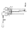
- FIG 4 shows an isolation of the internal structure of the bubbler of the second embodiment without the sidewall 12 being illustrated.
- the diptube inlet 14 and its outlet frit 18 are easily seen and the splash guard comprising baffle disc 22 and 24 are also readily seen with their concave downward shape.
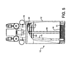
- FIG 5 shows a specific configuration of the second embodiment of FIG 2 in which the gas diffuser outlet 18 is shown as a horizontally disposed elongated cylindrical porous metal frit having a hollow gas passage interior and a porous metal frit outer shell, such as those made by Mott Corporation, Farmington, CT 06032, USA.
- the porous metal frit gas diffuser outlet 18 has a media grade rating to filter out particles of 1 micron or larger, preferably filtering out at least 90% of particles 1 micron or larger.
- the gas diffuser outlet 18 of FIG 5 is situated in a sump 21 in the base, floor or bottom of the bubbler container 12.
- the preferred diffuser 18 is an horizontally disposed elongated cylinder and the sump is thus a partial elongated cylinder open at its upper side to the inside of the bubbler and being of a dimension slightly larger than the elongated cylinder of the diffuser outlet 18, sufficient to allow gas bubbles of carrier gas to escape the outside of the diffuser outlet 18 and to allow liquid chemical precursor stored in the bubbler or vessel 10 to reside in the sump 21 substantially or completely surrounding the diffuser outlet 18.
- the diffuser outlet 18 resides entirely with the sump 21, such that the upper surface of the diffuser is no more than even with the upper edge of the sump wall.
- the level sensor 28 measures the liquid product level.
- Inlet 14 is controlled by inlet valve 30, and outlet 16 is controlled by valve 26.
- the goal with the configuration in FIG 5 is to provide adequate flow of gas to entrain liquid product without creating bubbles of such size as to create splashing or violent spitting of the liquid getting to the outlet and downstream of the bubbler. This could contaminate the outlet or create flow problems in any downstream mass flow controller.
- a metal frit 32 can be positioned at an inlet to the outlet 16.
- FIG 6 shows the embodiment of FIG 5 in which an elbow configuration or shape 34 of the inlet to the outlet 16 is used in place of metal frit 32.
- the end of elbow 34 is directed radially inward away from the outer circumferential or perimeter edge of the baffle discs 22 and 24 and toward the axial center of the cylinder formed by the sidewall 12 of the vessel or bubbler 10 to minimize possible liquid introduction into the outlet 16.
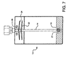
- FIG 7 shows an alternate to FIG 6 wherein the elbow outlet 34 is replaced with a "Tee" shaped or configured inlet 36 to the outlet, again to minimize the possible introduction of liquid into the outlet 16 from the annular space between the baffle discs 22 and 24 and the inside wall of the sidewall 12 of the vessel or bubbler 10.
- FIG 8 shows lower baffle disc 22 with a plurality of perforations 38 to trap liquid spitting between baffle discs 22 and 24 and return it to the sump of the vessel.
- FIG 9 shows that upper baffle disc 24 is fabricated from porous metal frit material, to again minimize liquid introduction into the outlet 16.
- the present invention provides superior minimization of liquid entrainment of droplets in the outlet and downstream piping of a bubbler connected to a CVD tool of an electronics fabrication system.
- Using either a single baffle disc or multiples of the baffle disc, alone or in combination with a diffuser or frit at an outlet to the diptube inlet provides the desired minimization of liquid droplet entrainment in the outlet 16 of the bubbler.
- baffle discs have been shown as circular discs with a concavity where the disc is slightly smaller than the inside diameter of the cylindrical vessel or bubbler sidewall, it is understood that any baffle of any shape which provides only a narrow annular space at the inner sidewall of the vessel or bubbler is within the scope of the present invention. Likewise, any form of device with an array of small passages can be used as the frit or outlet of the diptube of the present invention.
- the vessel 10 can also be used for product flow in the opposite direction where outlet 16 functions as a pressurizing gas inlet to form a pressure head on liquid contained in the vessel 10 and force the liquid in liquid form through the frit 18 and out the diptube 14 for liquid delivery from the vessel using a pressurizing gas, in contrast to the vapor delivery described above.
- outlet 16 functions as a pressurizing gas inlet to form a pressure head on liquid contained in the vessel 10 and force the liquid in liquid form through the frit 18 and out the diptube 14 for liquid delivery from the vessel using a pressurizing gas, in contrast to the vapor delivery described above.
Abstract
Description
- The electronics fabrication industry uses chemical precursor containers that convert liquid chemicals into chemical vapor for delivery to electronics fabrication reactors, i.e. tools, for conducting chemical vapor deposition ("CVD"). CVD is a favored technique for forming layers, films and other depositions in the construction of electronic fabrications such as integrated circuits or computer chips. Liquids or solids are preferred as sources of supply because of the efficiency of transport and storage of a volume of chemical precursor, but the industry frequently prefers to actually deliver the chemical precursor at the site of the tool in the form of a vapor, i.e. CVD. Alternatively, some fabrications are conducted using direct liquid injection ("DLI"), although even then, the liquid is vaporized in the tool after delivery.
- When using vapor delivery for CVD, the containers typically have an inert carrier gas passed through them or bubbled, i.e., bubbler, to carry entrained chemical precursor vapor in the inert carrier gas to the tool. Bubblers typically have a downtube inlet where the carrier gas is introduced into the container under the surface of the liquid chemical precursor wherein the carrier gas bubbles up through the liquid chemical precursor, entraining the chemical precursor as the carrier gas surfaces the liquid as a bubble and exits the container or bubbler by an outlet set above the liquid level of the chemical precursor.
- It is undesirable to have the chemical precursor leave the container through the outlet in the liquid form, even as small droplets. A homogenous vapor is preferred as the dispensed product of such bubblers. This avoids corrosion, cleanup, and uneven flow, especially through mass flow controllers which control the flow of chemical precursor from the bubbler to the tool in a precisely metered fashion.
- The industry has attempted various forms of splashguards for bubblers to address this issue, such as in:
US 6,520,218 ;EP 1 329 540 ;US 2004/0013577 ;EP 0 420 596 ;US 5,589,110 ;US 7,077,388 ;US 2003/0042630 ;US 5,776,255 ; andUS 4,450,118 . Each of these attempts to provide splashguard function has had less than desired performance, but the present invention as disclosed below successfully provides high levels of splashguard function, while still allowing high flows of chemical precursor or flows under high vacuum or high pressure differential conditions as will be described and illustrated below. - The present invention is a bubbler having a diptube inlet ending in a bubble size reducing outlet and at least one baffle disc positioned between the outlet of the diptube and the outlet of the bubbler configured to provide a narrow annular space between the baffle disc and the inside wall of the bubbler capable of preventing liquid droplets from entering the outlet to the bubbler. The bubble size reducing outlet is a tubular porous diffuser situated in a sump in the floor or bottom of the bubbler container wherein the sump is shaped to the approximate size and shape of the diffuser with sufficient tolerance to allow bubbles to escape the diffuser and liquid product to surround the diffuser in the sump.
- The present invention is also a process of delivering a chemical precursor from a bubbler vessel comprising; passing a carrier gas through a diptube of a bubbler and further through a bubble size reducing outlet, such as a diffuser in a sump; entraining liquid chemical precursor from the bubbler into the carrier gas; passing the entrained chemical precursor and carrier gas past at least one baffle disc in a narrow annular space between the outer perimeter of the baffle disc and the inner surface of bubbler sidewall.
-
-
FIG 1 is a schematic side view of a first embodiment of the present invention. -
FIG 2 is a schematic side view of a second embodiment of the present invention. -
FIG 3 is a detailed schematic side view of the second embodiment of the present invention ofFIG 2 . -
FIG 4 is a detailed schematic side view of the inner function structures of the second embodiment of the present invention ofFIG 3 . -
FIG 5 is a detailed schematic side view of the inner function structures of the second embodiment of the present invention ofFIG 2 showing a diffuser in a sump configured to the approximate shape of the diffuser. -
FIG 6 is a detailed schematic side view of the inner function structures ofFIG 5 showing analternate elbow outlet 34. -
FIG 7 is a detailed schematic side view of the inner function structures ofFIG 5 showing an alternate "Tee"outlet 36. -
FIG 8 is a detailed schematic side view of the inner function structures ofFIG 4 showing an alternate embodiment wherebaffle disc 22 has perforations 38. -
FIG 9 is a detailed schematic side view of the inner function structures ofFIG 4 showing an alternate embodiment wherebaffle disc 24 is constructed of a porous metal frit material. - The present invention is a vapor generation bubbler designed for service in high vacuum or high flowrate conditions. The design prevents splashing and transport of aerosol droplets into the outlet delivery line that would result in erratic chemical mass flow delivery.
- Semiconductor manufacturers are turning to the use of high value chemicals that are increasingly difficult to transport for deposition onto a wafer in a vacuum chamber or tool. The vessel or bubbler of the present invention allows liquid chemical to be delivered from the container or bubbler as a vapor at high vacuum, without the splashing and the formation of aerosol droplets in the outlet of the vessel or bubbler that result in erratic chemical mass delivery rate. The present invention has a lower surface design that enables a constant saturation of a carrier gas with chemical vapor down to very low levels of the residual chemical. Yet, the present invention prevents splashing and the formation of aerosol droplets into the outlet of the bubbler, that would result in erratic chemical mass delivery rate, even when the chemical level in the container is high. Previously, bubblers used for high vacuum service or high flowrate service had to be used with only a partial charge of chemical (i.e.: 50% full). This required the semiconductor manufacturer to change the vessel or bubbler more often (taking down the tool), and added to the cost of the chemical, because of the increased container processing fees. This invention enables use of the bubbler from a full liquid chemical level down to a very low level and reduces semiconductor tool downtime. Also, since it is effective at limiting the chemical aerosol particles in the outlet, it can reduce particulate generation that might result from degradation of the aerosol droplets that deposit in the outlet and all of the delivery piping to the processing chamber or tool.
- Previous bubbler designs addressed the problem of splashing by installing at the bottom of the dip tube, piping, perpendicular to the diptube, with holes drilled along its length. This resulted in smaller bubbles generated over a larger area of the bubbler, which resulted in a less turbulent bubbling action, and therefore, less splashing, but these inventions are impossible to effectively clean for reuse by the chemical supplier.
- The present invention uses porous masses of material, such as porous metal frits, at the outlet of the inlet diptube to break down the size of the bubbles of inert carrier gas entering the liquid chemical precursor in conjunction with one or more baffle discs at the upper part of the vessel or bubbler that requires the carrier gas entrained with chemical precursor to pass indirectly to the outlet of the container or bubbler by flowing tortuously to the outside of the baffle discs in a narrow annular space between the inner diameter of the bubbler inside wall and the outer diameter or circumferential or perimeter edge of the baffle discs. This will be illustrated with reference to several preferred embodiments of the present invention.
-
FIG1 shows abubbler 10 of the present invention having acylindrical bubbler sidewall 12 with adiptube inlet 14 terminating at its inlet end with a porous mass or block outlet, such as a stainless steel frit 18 that operates as a gas diffuser to generate small microbubbles of the inert carrier gas below the surface of the liquid chemical precursor (not illustrated). This reduces the chance of violent bubbling or the splattering of liquid above the headspace or freeboard of the bubbler. Theoutlet 18 of thebubbler diptube inlet 14 is proximate the floor of the bubbler in asump 21, shown inFIG 5 . - In addition, the
diptube 14 has abaffle disc 20, having a circular and concave downward configuration like a shallow cone opening downward, affixed, as by welding, to the upper end of thediptube 14, to further avoid liquid splattering or large scale liquid entrainment of the carrier gas flowing to theoutlet 16, which is undesired, but which has a greater probability under high flow or high vacuum conditions. -
FIG 2 shows a second embodiment of the present invention where similar parts have similar part numbers. Here the splash guard comprises two baffle discs, alower baffle disc 22 and anupper baffle disc 24 having a circular outer edge shape and being concave downward, such as a shallow downwardly open cone, that act in cooperation to make an even more tortuous path for chemical precursor leaving thebubbler 10. The baffle discs are concave downward to further frustrate direct flow of chemical precursor to theoutlet 16 and to collect condensed chemical precursor for return by coalesced droplets falling back into the stored chemical precursor (not illustrated). The baffle discs have a diameter slightly less than the inside diameter of the cylindrical inside wall of the bubbler. The space between the circumferential or perimeter edge of the baffle disc and the inside wall of the bubbler is sufficient to allow gas to pass through the space with minimal pressure drop, but sufficiently narrow to minimize the passage of liquid that may be ejected from the liquid content of the bubbler under high flow rates of carrier gas through the diptube or significant pressure fluctuations. -
FIG 3 shows a more detailed illustration of the second embodiment of the present invention. Bubbler 10 is shown in cut away with anangled diptube 14 ending in a stainless steel frit outlet18, such as a Mott porous stainless steel cup Series 1200, catalog no 1200-A-B-L-Media grade. The twobaffle discs container sidewall 12 so that thelower baffle disc 22 allows greater annular space from the cylindrical inside surface of thebubbler sidewall 12 for carrier gas and chemical precursor to pass toward the outlet, whileupper baffle disc 24 provides less annular space to further avoid liquid entrainment in the outlet and downstream piping from the outlet. -
FIG 4 shows an isolation of the internal structure of the bubbler of the second embodiment without thesidewall 12 being illustrated. InFIG 4 , thediptube inlet 14 and its outlet frit 18 are easily seen and the splash guard comprisingbaffle disc -
FIG 5 shows a specific configuration of the second embodiment ofFIG 2 in which thegas diffuser outlet 18 is shown as a horizontally disposed elongated cylindrical porous metal frit having a hollow gas passage interior and a porous metal frit outer shell, such as those made by Mott Corporation, Farmington, CT 06032, USA. Preferably, the porous metal fritgas diffuser outlet 18 has a media grade rating to filter out particles of 1 micron or larger, preferably filtering out at least 90% of particles 1 micron or larger. - The
gas diffuser outlet 18 ofFIG 5 is situated in asump 21 in the base, floor or bottom of thebubbler container 12. Thepreferred diffuser 18 is an horizontally disposed elongated cylinder and the sump is thus a partial elongated cylinder open at its upper side to the inside of the bubbler and being of a dimension slightly larger than the elongated cylinder of thediffuser outlet 18, sufficient to allow gas bubbles of carrier gas to escape the outside of thediffuser outlet 18 and to allow liquid chemical precursor stored in the bubbler orvessel 10 to reside in thesump 21 substantially or completely surrounding thediffuser outlet 18. Preferably, thediffuser outlet 18 resides entirely with thesump 21, such that the upper surface of the diffuser is no more than even with the upper edge of the sump wall. Thelevel sensor 28 measures the liquid product level.Inlet 14 is controlled byinlet valve 30, andoutlet 16 is controlled byvalve 26. The goal with the configuration inFIG 5 is to provide adequate flow of gas to entrain liquid product without creating bubbles of such size as to create splashing or violent spitting of the liquid getting to the outlet and downstream of the bubbler. This could contaminate the outlet or create flow problems in any downstream mass flow controller. To further avoid liquid escape from the bubbler, ametal frit 32 can be positioned at an inlet to theoutlet 16. -
FIG 6 shows the embodiment ofFIG 5 in which an elbow configuration orshape 34 of the inlet to theoutlet 16 is used in place ofmetal frit 32. The end ofelbow 34 is directed radially inward away from the outer circumferential or perimeter edge of thebaffle discs sidewall 12 of the vessel orbubbler 10 to minimize possible liquid introduction into theoutlet 16. - Similarly,
FIG 7 shows an alternate toFIG 6 wherein theelbow outlet 34 is replaced with a "Tee" shaped or configuredinlet 36 to the outlet, again to minimize the possible introduction of liquid into theoutlet 16 from the annular space between thebaffle discs sidewall 12 of the vessel orbubbler 10. - To avoid liquid introduction into the
outlet 16, it is further possible to change the construction of the baffle discs.FIG 8 showslower baffle disc 22 with a plurality of perforations 38 to trap liquid spitting betweenbaffle discs FIG 9 shows thatupper baffle disc 24 is fabricated from porous metal frit material, to again minimize liquid introduction into theoutlet 16. - The present invention provides superior minimization of liquid entrainment of droplets in the outlet and downstream piping of a bubbler connected to a CVD tool of an electronics fabrication system. Using either a single baffle disc or multiples of the baffle disc, alone or in combination with a diffuser or frit at an outlet to the diptube inlet provides the desired minimization of liquid droplet entrainment in the
outlet 16 of the bubbler. - Although the baffle discs have been shown as circular discs with a concavity where the disc is slightly smaller than the inside diameter of the cylindrical vessel or bubbler sidewall, it is understood that any baffle of any shape which provides only a narrow annular space at the inner sidewall of the vessel or bubbler is within the scope of the present invention. Likewise, any form of device with an array of small passages can be used as the frit or outlet of the diptube of the present invention.
- Although, it is preferred to use stainless steel, it is envisioned that any inert material of rigid form can be used for the splash guard or frit. Plastics, metal alloys, powdered metals, fabrics, textiles and ceramics are all contemplated.
- The
vessel 10 can also be used for product flow in the opposite direction whereoutlet 16 functions as a pressurizing gas inlet to form a pressure head on liquid contained in thevessel 10 and force the liquid in liquid form through the frit 18 and out thediptube 14 for liquid delivery from the vessel using a pressurizing gas, in contrast to the vapor delivery described above.
Claims (26)
- A bubbler having: a diptube inlet ending in a bubble size reducing outlet; and at least one baffle disc positioned between the outlet of the diptube and an outlet of the bubbler and configured to provide a narrow annular space between the baffle disc and an inside wall of the bubbler capable of minimizing liquid droplets from entering the outlet to the bubbler.
- The bubbler of Claim 1, the bubbler having: a diptube inlet ending in a bubble size reducing outlet proximate a floor of the bubbler; and at least one baffle disc positioned between the outlet of the diptube and an outlet of the bubbler and configured to provide a narrow annular space between the baffle disc and an inside wall of the bubbler capable of minimizing liquid droplets from entering the outlet to the bubbler.
- The bubbler of any preceding claim, wherein the diptube inlet ending in a bubble size reducing outlet is a diffuser.
- The bubbler of Claim 3 wherein the diptube ending in a bubble size reducing outlet is an elongated cylindrical diffuser.
- The bubbler of Claim 3 or 4 wherein the diffuser is constructed of a porous metal frit.
- The bubbler of any one of Claims 3 to 5 wherein the diffuser has porosity to filter out particles of 1 micron or larger.
- The bubbler of Claim 6 wherein the diffuser has porosity to filter out greater than 90% of particles of 1 micron or larger.
- The bubbler of any one of Claims 3 to 7 wherein the diffuser is situated in a sump in the floor of the bubbler.
- The bubbler of claim 8, wherein the sump has a configuration larger than the diffuser's outside dimension sufficient to allow gas bubbles to escape the outside of the diffuser and to allow liquid to reside in the sump surrounding the diffuser.
- The bubbler of Claim 8 or 9 wherein the sump is a partial elongated cylinder larger that the diffuser.
- The bubbler of any preceding claim wherein an inlet to the outlet of the bubbler has a porous frit to minimize liquid entering the outlet of the bubbler.
- The bubbler of any preceding claim wherein an inlet to the outlet of the bubbler has an elbow configuration to minimize liquid entering the outlet to the bubbler.
- The bubbler of any one of Claims 1 to 11 wherein an inlet to the outlet of the bubbler has a "Tee" configuration to minimize liquid entering the outlet of the bubbler.
- The bubbler of any preceding claim having at least two baffle discs comprising an upper baffle disc and a lower baffle disc.
- The bubbler of Claim 14, wherein the lower baffle disc has perforations in it.
- The bubbler of Claim 14 or 15, wherein the upper baffle disc is fabricated of porous metal frit.
- The bubbler of any preceding claim wherein the bubbler has a cylindrical shape.
- The bubbler of any preceding claim wherein the baffle disc or discs have a circular shape.
- The bubbler of any preceding claim wherein the baffle disc or discs have a concave downward shape.
- The bubbler of Claim 1, wherein the bubbler is a cylindrical vapor generation bubbler vessel having a diptube inlet ending in a bubble size reducing diffuser outlet of a porous metal frit for delivering a carrier gas into the bubbler vessel and two baffle discs having a circular and concave downward shape, comprising an upper baffle disc and a lower baffle disc, positioned between an outlet to the diptube inlet and an outlet of the bubbler vessel configured to provide a narrow annular space between an outer circumferential perimeter edge of the baffle discs and the inside wall of the bubbler vessel capable of minimizing liquid droplets from entering the outlet to the bubbler vessel when the carrier gas is bubbled through a liquid content of the bubbler vessel to dispense the liquid as a vapor from the bubbler vessel and an inlet to the outlet of the bubbler vessel having a configuration selected from the group consisting of an elbow and a Tee shape.
- A liquid dispense vessel having a diptube outlet having a porous metal frit inlet end and an inlet to the vessel above the liquid level of the liquid chemical precursor in the vessel.
- The liquid dispense vessel of Claim 21 having at least one baffle disc positioned between the inlet end to the diptube outlet and the inlet of the liquid dispense vessel and configured to provide a narrow annular space between the baffle disc and the inside wall of the bubbler capable of minimizing liquid droplets from entering the inlet to the liquid dispense vessel.
- A process of delivering a vapor from a bubbler comprising; passing a carrier gas through a diptube of the bubbler and further through a bubble size reducing outlet; entraining liquid from the bubbler into the carrier gas; and passing the entrained liquid vapor and carrier gas past at least one baffle disc in a narrow annular space between the outer perimeter of the baffle disc and the inner surface of the bubbler sidewall.
- The process of Claim 23 wherein the bubbler, diptube, and/or baffle disk or disks are as further defined in any one of Claims 1 to 20.
- A process of delivering a liquid chemical precursor from a vessel comprising; introducing a pressurizing gas into an inlet to the vessel above the liquid level of the liquid chemical precursor in the vessel to force the liquid chemical precursor through a metal frit filter as an inlet to a diptube outlet of the vessel.
- The process of Claim 25 wherein the pressurizing gas passes at least one baffle disc in a narrow annular space between the outer perimeter of the baffle disc and the inner surface of the vessel sidewall.
Applications Claiming Priority (3)
| Application Number | Priority Date | Filing Date | Title |
|---|---|---|---|
| US87520006P | 2006-12-15 | 2006-12-15 | |
| US90837607P | 2007-03-27 | 2007-03-27 | |
| US11/939,109 US8708320B2 (en) | 2006-12-15 | 2007-11-13 | Splashguard and inlet diffuser for high vacuum, high flow bubbler vessel |
Publications (3)
| Publication Number | Publication Date |
|---|---|
| EP1932942A2 true EP1932942A2 (en) | 2008-06-18 |
| EP1932942A3 EP1932942A3 (en) | 2011-05-11 |
| EP1932942B1 EP1932942B1 (en) | 2018-05-16 |
Family
ID=39110552
Family Applications (1)
| Application Number | Title | Priority Date | Filing Date |
|---|---|---|---|
| EP07123198.9A Active EP1932942B1 (en) | 2006-12-15 | 2007-12-14 | Splashguard and inlet diffuser for high vacuum, high flow bubbler vessel |
Country Status (6)
| Country | Link |
|---|---|
| US (3) | US8708320B2 (en) |
| EP (1) | EP1932942B1 (en) |
| JP (1) | JP4787230B2 (en) |
| KR (1) | KR100996344B1 (en) |
| CN (1) | CN101205604B (en) |
| TW (1) | TWI369414B (en) |
Cited By (3)
| Publication number | Priority date | Publication date | Assignee | Title |
|---|---|---|---|---|
| WO2010103487A1 (en) * | 2009-03-11 | 2010-09-16 | L'air Liquide-Societe Anonyme Pour L'etude Et L'exploitation Des Procedes Georges Claude | Bubbling supply system for stable precursor supply |
| US8944420B2 (en) | 2009-03-19 | 2015-02-03 | Air Products And Chemicals, Inc. | Splashguard for high flow vacuum bubbler vessel |
| US20150276264A1 (en) * | 2014-03-27 | 2015-10-01 | Lam Research Corporation | Systems and methods for bulk vaporization of precursor |
Families Citing this family (18)
| Publication number | Priority date | Publication date | Assignee | Title |
|---|---|---|---|---|
| US6921062B2 (en) | 2002-07-23 | 2005-07-26 | Advanced Technology Materials, Inc. | Vaporizer delivery ampoule |
| GB2432371B (en) * | 2005-11-17 | 2011-06-15 | Epichem Ltd | Improved bubbler for the transportation of substances by a carrier gas |
| US20080241805A1 (en) | 2006-08-31 | 2008-10-02 | Q-Track Corporation | System and method for simulated dosimetry using a real time locating system |
| US8708320B2 (en) * | 2006-12-15 | 2014-04-29 | Air Products And Chemicals, Inc. | Splashguard and inlet diffuser for high vacuum, high flow bubbler vessel |
| US20100119734A1 (en) * | 2008-11-07 | 2010-05-13 | Applied Materials, Inc. | Laminar flow in a precursor source canister |
| US8162296B2 (en) * | 2009-03-19 | 2012-04-24 | Air Products And Chemicals, Inc. | Splashguard for high flow vacuum bubbler vessel |
| WO2011053505A1 (en) | 2009-11-02 | 2011-05-05 | Sigma-Aldrich Co. | Evaporator |
| CN102092962A (en) * | 2011-01-05 | 2011-06-15 | 成都中住光纤有限公司 | Fiber coating filling device |
| TWI480418B (en) * | 2012-01-16 | 2015-04-11 | Air Prod & Chem | Splashguard for high flow vacuum bubbler vessel |
| US9598766B2 (en) * | 2012-05-27 | 2017-03-21 | Air Products And Chemicals, Inc. | Vessel with filter |
| CN109972119A (en) | 2012-05-31 | 2019-07-05 | 恩特格里斯公司 | The conveying of the high species flux fluid for batch deposition based on source reagent |
| US9957612B2 (en) * | 2014-01-17 | 2018-05-01 | Ceres Technologies, Inc. | Delivery device, methods of manufacture thereof and articles comprising the same |
| US9682393B2 (en) * | 2015-03-17 | 2017-06-20 | Ecolab Usa Inc. | Fitment splash guard |
| US10443128B2 (en) * | 2015-04-18 | 2019-10-15 | Versum Materials Us, Llc | Vessel and method for delivery of precursor materials |
| US11926894B2 (en) * | 2016-09-30 | 2024-03-12 | Asm Ip Holding B.V. | Reactant vaporizer and related systems and methods |
| KR102344996B1 (en) * | 2017-08-18 | 2021-12-30 | 삼성전자주식회사 | Unit for supplying precursor, substrate processing apparatus and method for manufacturing semiconductor device using the same |
| KR20200130121A (en) * | 2019-05-07 | 2020-11-18 | 에이에스엠 아이피 홀딩 비.브이. | Chemical source vessel with dip tube |
| US20220145456A1 (en) * | 2020-11-09 | 2022-05-12 | Applied Materials, Inc. | Refillable large volume solid precursor sublimation vessel |
Citations (9)
| Publication number | Priority date | Publication date | Assignee | Title |
|---|---|---|---|---|
| US4450118A (en) | 1981-04-29 | 1984-05-22 | U.S. Philips Corporation | Apparatus for saturating a gas with the vapor of a liquid |
| EP0420596A1 (en) | 1989-09-26 | 1991-04-03 | Canon Kabushiki Kaisha | Gas feeding device and deposition film forming apparatus employing the same |
| US5589110A (en) | 1992-11-20 | 1996-12-31 | Mitsubishi Electric Corp | Container for liquid metal organic compound |
| US5776255A (en) | 1992-12-24 | 1998-07-07 | Canon Kabushiki Kaisha | Chemical vapor deposition apparatus |
| US6520218B1 (en) | 1998-09-03 | 2003-02-18 | Advanced Technology Materials, Inc. | Container chemical guard |
| US20030042630A1 (en) | 2001-09-05 | 2003-03-06 | Babcoke Jason E. | Bubbler for gas delivery |
| EP1329540A2 (en) | 2000-07-03 | 2003-07-23 | Epichem Limited | An apparatus for the delivery of precursors in the vapour phase to epitaxial reactor sites |
| US20040013577A1 (en) | 2002-07-17 | 2004-01-22 | Seshadri Ganguli | Method and apparatus for providing gas to a processing chamber |
| US7077388B2 (en) | 2002-07-19 | 2006-07-18 | Asm America, Inc. | Bubbler for substrate processing |
Family Cites Families (45)
| Publication number | Priority date | Publication date | Assignee | Title |
|---|---|---|---|---|
| US1339609A (en) * | 1917-07-02 | 1920-05-11 | Stinson Tractor Company | Dust-collector for carbureters |
| US1756204A (en) * | 1926-12-16 | 1930-04-29 | William F Rawlings | Vacuum-cleaner apparatus |
| US1912439A (en) * | 1932-03-29 | 1933-06-06 | Feller Maximilian | Beverage manufacture |
| US1994766A (en) * | 1934-06-25 | 1935-03-19 | George L Heglar | Air cleaner and washer |
| US2405494A (en) * | 1944-03-29 | 1946-08-06 | Cedar Corp N O | Air treating apparatus |
| US2742886A (en) * | 1954-11-01 | 1956-04-24 | Solomon P Scholl | Fuel generator for internal combustion engines |
| US3542524A (en) * | 1967-10-10 | 1970-11-24 | Harry E Kimble | Oxygen generating apparatus for aquariums and other oxygen requirement systems |
| US4350505A (en) * | 1976-12-17 | 1982-09-21 | Loffland Brothers Company | Device for reduction of oxygen content in drilling fluid |
| US4140735A (en) | 1977-08-15 | 1979-02-20 | J. C. Schumacher Co. | Process and apparatus for bubbling gas through a high purity liquid |
| US4493637A (en) * | 1978-02-15 | 1985-01-15 | Thermics Corporation Liquidating Trust | Fossil fuel catalyst generator |
| US4251485A (en) * | 1978-03-28 | 1981-02-17 | Schauer John M | Apparatus for cleansing noxious constituents from gas streams |
| JPS6231121Y2 (en) | 1978-06-30 | 1987-08-10 | ||
| JPS60111417A (en) | 1983-11-22 | 1985-06-17 | Mitsubishi Electric Corp | Carburetor utilizing liquid bubbling |
| JPS6283400A (en) * | 1985-10-02 | 1987-04-16 | Toyo Sutoufuaa Chem:Kk | Method of improving cylinder for vapor growth of organometallic compound |
| JPS6311598A (en) * | 1986-07-03 | 1988-01-19 | Toyo Sutoufuaa Chem:Kk | Cylinder for organometal vapor growth |
| JPS63149521A (en) | 1986-12-12 | 1988-06-22 | Fuji Electric Co Ltd | Liquid level measuring apparatus of solid dissolved liquid receiving tank |
| DE3708967A1 (en) | 1987-03-19 | 1988-10-06 | Merck Patent Gmbh | DEVICE FOR GENERATING A GAS MIXTURE BY THE SATURATION PROCESS |
| JPS63149521U (en) * | 1987-03-20 | 1988-10-03 | ||
| KR890004163A (en) | 1987-08-12 | 1989-04-20 | 고마쯔 신 | Dissolved Gas in Water |
| JPH04356915A (en) | 1991-06-03 | 1992-12-10 | Nissin Electric Co Ltd | Gas source cell |
| EP0555614A1 (en) | 1992-02-13 | 1993-08-18 | International Business Machines Corporation | Metal-organic gas supply for MOVPE and MOMBE |
| JPH05335243A (en) | 1992-06-03 | 1993-12-17 | Mitsubishi Electric Corp | Liquid bubbling apparatus |
| US5199963A (en) * | 1992-07-30 | 1993-04-06 | Scarp Arcoline J | Dual filtering vacuum system |
| JP2000252269A (en) * | 1992-09-21 | 2000-09-14 | Mitsubishi Electric Corp | Equipment and method for liquid vaporization |
| JPH06241132A (en) | 1993-02-19 | 1994-08-30 | Aqueous Res:Kk | Hydrogen addition system and method for operating same |
| JPH06283400A (en) | 1993-03-26 | 1994-10-07 | Nikon Corp | Spacing measuring device |
| KR100364115B1 (en) | 1996-12-17 | 2002-12-11 | 어드밴스드 테크놀러지 머티리얼즈, 인코포레이티드 | Reagent supply vessel for chemical vapor deposition |
| US6544522B1 (en) | 1998-12-30 | 2003-04-08 | Corixa Corporation | Fusion proteins of mycobacterium tuberculosis antigens and their uses |
| AU9507298A (en) | 1997-09-26 | 1999-04-23 | Advanced Technology Materials, Inc. | Liquid reagent delivery system |
| US6220091B1 (en) | 1997-11-24 | 2001-04-24 | Applied Materials, Inc. | Liquid level pressure sensor and method |
| US6444038B1 (en) | 1999-12-27 | 2002-09-03 | Morton International, Inc. | Dual fritted bubbler |
| JP2003511217A (en) * | 1999-10-07 | 2003-03-25 | ペレテックス インコーポレイテッド | Method and apparatus for filtering an air stream containing aqueous foam |
| CA2329860A1 (en) * | 1999-12-30 | 2001-06-30 | Angelo Sanchez | Liquid spray absorbing |
| JP2001313288A (en) | 2000-04-28 | 2001-11-09 | Ebara Corp | Source-gas supplying device |
| US6736154B2 (en) | 2001-01-26 | 2004-05-18 | American Air Liquide, Inc. | Pressure vessel systems and methods for dispensing liquid chemical compositions |
| US6561498B2 (en) | 2001-04-09 | 2003-05-13 | Lorex Industries, Inc. | Bubbler for use in vapor generation systems |
| TW200300701A (en) | 2001-11-30 | 2003-06-16 | Asml Us Inc | High flow rate bubbler system and method |
| US7300038B2 (en) * | 2002-07-23 | 2007-11-27 | Advanced Technology Materials, Inc. | Method and apparatus to help promote contact of gas with vaporized material |
| US7011299B2 (en) | 2002-09-16 | 2006-03-14 | Matheson Tri-Gas, Inc. | Liquid vapor delivery system and method of maintaining a constant level of fluid therein |
| US7124913B2 (en) * | 2003-06-24 | 2006-10-24 | Air Products And Chemicals, Inc. | High purity chemical container with diptube and level sensor terminating in lowest most point of concave floor |
| US7722720B2 (en) | 2004-12-08 | 2010-05-25 | Rohm And Haas Electronic Materials Llc | Delivery device |
| US7464917B2 (en) * | 2005-10-07 | 2008-12-16 | Appiled Materials, Inc. | Ampoule splash guard apparatus |
| US8708320B2 (en) * | 2006-12-15 | 2014-04-29 | Air Products And Chemicals, Inc. | Splashguard and inlet diffuser for high vacuum, high flow bubbler vessel |
| US8162296B2 (en) * | 2009-03-19 | 2012-04-24 | Air Products And Chemicals, Inc. | Splashguard for high flow vacuum bubbler vessel |
| US8944420B2 (en) * | 2009-03-19 | 2015-02-03 | Air Products And Chemicals, Inc. | Splashguard for high flow vacuum bubbler vessel |
-
2007
- 2007-11-13 US US11/939,109 patent/US8708320B2/en active Active
- 2007-12-10 KR KR1020070127377A patent/KR100996344B1/en active IP Right Grant
- 2007-12-11 JP JP2007319061A patent/JP4787230B2/en active Active
- 2007-12-11 TW TW096147313A patent/TWI369414B/en active
- 2007-12-14 EP EP07123198.9A patent/EP1932942B1/en active Active
- 2007-12-14 CN CN2007103009366A patent/CN101205604B/en active Active
-
2014
- 2014-03-12 US US14/205,601 patent/US20140193578A1/en not_active Abandoned
- 2014-03-12 US US14/205,786 patent/US9435027B2/en active Active
Patent Citations (9)
| Publication number | Priority date | Publication date | Assignee | Title |
|---|---|---|---|---|
| US4450118A (en) | 1981-04-29 | 1984-05-22 | U.S. Philips Corporation | Apparatus for saturating a gas with the vapor of a liquid |
| EP0420596A1 (en) | 1989-09-26 | 1991-04-03 | Canon Kabushiki Kaisha | Gas feeding device and deposition film forming apparatus employing the same |
| US5589110A (en) | 1992-11-20 | 1996-12-31 | Mitsubishi Electric Corp | Container for liquid metal organic compound |
| US5776255A (en) | 1992-12-24 | 1998-07-07 | Canon Kabushiki Kaisha | Chemical vapor deposition apparatus |
| US6520218B1 (en) | 1998-09-03 | 2003-02-18 | Advanced Technology Materials, Inc. | Container chemical guard |
| EP1329540A2 (en) | 2000-07-03 | 2003-07-23 | Epichem Limited | An apparatus for the delivery of precursors in the vapour phase to epitaxial reactor sites |
| US20030042630A1 (en) | 2001-09-05 | 2003-03-06 | Babcoke Jason E. | Bubbler for gas delivery |
| US20040013577A1 (en) | 2002-07-17 | 2004-01-22 | Seshadri Ganguli | Method and apparatus for providing gas to a processing chamber |
| US7077388B2 (en) | 2002-07-19 | 2006-07-18 | Asm America, Inc. | Bubbler for substrate processing |
Cited By (6)
| Publication number | Priority date | Publication date | Assignee | Title |
|---|---|---|---|---|
| WO2010103487A1 (en) * | 2009-03-11 | 2010-09-16 | L'air Liquide-Societe Anonyme Pour L'etude Et L'exploitation Des Procedes Georges Claude | Bubbling supply system for stable precursor supply |
| US8348248B2 (en) | 2009-03-11 | 2013-01-08 | L'air Liquide Societe Anonyme Pour L'etude Et L'exploitation Des Procedes Georges Claude | Bubbling supply system for stable precursor supply |
| US8944420B2 (en) | 2009-03-19 | 2015-02-03 | Air Products And Chemicals, Inc. | Splashguard for high flow vacuum bubbler vessel |
| US20150276264A1 (en) * | 2014-03-27 | 2015-10-01 | Lam Research Corporation | Systems and methods for bulk vaporization of precursor |
| US9964332B2 (en) * | 2014-03-27 | 2018-05-08 | Lam Research Corporation | Systems and methods for bulk vaporization of precursor |
| TWI667365B (en) * | 2014-03-27 | 2019-08-01 | 美商蘭姆研究公司 | Systems and methods for bulk vaporization of precursor |
Also Published As
| Publication number | Publication date |
|---|---|
| US9435027B2 (en) | 2016-09-06 |
| TW200829715A (en) | 2008-07-16 |
| US20080143002A1 (en) | 2008-06-19 |
| CN101205604B (en) | 2012-07-04 |
| US20140191423A1 (en) | 2014-07-10 |
| CN101205604A (en) | 2008-06-25 |
| KR20080055644A (en) | 2008-06-19 |
| EP1932942B1 (en) | 2018-05-16 |
| JP2008150709A (en) | 2008-07-03 |
| US20140193578A1 (en) | 2014-07-10 |
| TWI369414B (en) | 2012-08-01 |
| JP4787230B2 (en) | 2011-10-05 |
| KR100996344B1 (en) | 2010-11-25 |
| US8708320B2 (en) | 2014-04-29 |
| EP1932942A3 (en) | 2011-05-11 |
Similar Documents
| Publication | Publication Date | Title |
|---|---|---|
| EP1932942B1 (en) | Splashguard and inlet diffuser for high vacuum, high flow bubbler vessel | |
| US8162296B2 (en) | Splashguard for high flow vacuum bubbler vessel | |
| TWI617695B (en) | Container for chemical precursors in a deposition process and method for storage and delivery of a liquid chemical precursor to a process tool | |
| US6874770B2 (en) | High flow rate bubbler system and method | |
| JP2005533179A (en) | Method and apparatus for supplying gas to a processing chamber | |
| JP2006352001A (en) | Treatment gas supply device and substrate processor | |
| TWI480418B (en) | Splashguard for high flow vacuum bubbler vessel | |
| US8944420B2 (en) | Splashguard for high flow vacuum bubbler vessel | |
| TWI675120B (en) | Aerosol-free vessel and method for bubbling chemical precursors in a deposition process | |
| JP2006294762A (en) | Substrate processing apparatus | |
| JP2004330111A (en) | Vacuum distillation unit | |
| JP2006289219A (en) | Mist generator | |
| JP2005131616A (en) | Evaporation apparatus for sparkling solution and evaporation method therefor |
Legal Events
| Date | Code | Title | Description |
|---|---|---|---|
| PUAI | Public reference made under article 153(3) epc to a published international application that has entered the european phase |
Free format text: ORIGINAL CODE: 0009012 |
|
| AK | Designated contracting states |
Kind code of ref document: A2 Designated state(s): AT BE BG CH CY CZ DE DK EE ES FI FR GB GR HU IE IS IT LI LT LU LV MC MT NL PL PT RO SE SI SK TR |
|
| AX | Request for extension of the european patent |
Extension state: AL BA HR MK RS |
|
| PUAL | Search report despatched |
Free format text: ORIGINAL CODE: 0009013 |
|
| AK | Designated contracting states |
Kind code of ref document: A3 Designated state(s): AT BE BG CH CY CZ DE DK EE ES FI FR GB GR HU IE IS IT LI LT LU LV MC MT NL PL PT RO SE SI SK TR |
|
| AX | Request for extension of the european patent |
Extension state: AL BA HR MK RS |
|
| 17P | Request for examination filed |
Effective date: 20111110 |
|
| AKX | Designation fees paid |
Designated state(s): AT BE BG CH CY CZ DE DK EE ES FI FR GB GR HU IE IS IT LI LT LU LV MC MT NL PL PT RO SE SI SK TR |
|
| 17Q | First examination report despatched |
Effective date: 20170116 |
|
| GRAP | Despatch of communication of intention to grant a patent |
Free format text: ORIGINAL CODE: EPIDOSNIGR1 |
|
| INTG | Intention to grant announced |
Effective date: 20170822 |
|
| RAP1 | Party data changed (applicant data changed or rights of an application transferred) |
Owner name: VERSUM MATERIALS US, LLC |
|
| GRAS | Grant fee paid |
Free format text: ORIGINAL CODE: EPIDOSNIGR3 |
|
| GRAA | (expected) grant |
Free format text: ORIGINAL CODE: 0009210 |
|
| AK | Designated contracting states |
Kind code of ref document: B1 Designated state(s): AT BE BG CH CY CZ DE DK EE ES FI FR GB GR HU IE IS IT LI LT LU LV MC MT NL PL PT RO SE SI SK TR |
|
| REG | Reference to a national code |
Ref country code: GB Ref legal event code: FG4D |
|
| REG | Reference to a national code |
Ref country code: CH Ref legal event code: EP |
|
| REG | Reference to a national code |
Ref country code: DE Ref legal event code: R096 Ref document number: 602007054833 Country of ref document: DE |
|
| REG | Reference to a national code |
Ref country code: IE Ref legal event code: FG4D |
|
| REG | Reference to a national code |
Ref country code: AT Ref legal event code: REF Ref document number: 999636 Country of ref document: AT Kind code of ref document: T Effective date: 20180615 |
|
| REG | Reference to a national code |
Ref country code: NL Ref legal event code: MP Effective date: 20180516 |
|
| REG | Reference to a national code |
Ref country code: LT Ref legal event code: MG4D |
|
| PG25 | Lapsed in a contracting state [announced via postgrant information from national office to epo] |
Ref country code: ES Free format text: LAPSE BECAUSE OF FAILURE TO SUBMIT A TRANSLATION OF THE DESCRIPTION OR TO PAY THE FEE WITHIN THE PRESCRIBED TIME-LIMIT Effective date: 20180516 Ref country code: LT Free format text: LAPSE BECAUSE OF FAILURE TO SUBMIT A TRANSLATION OF THE DESCRIPTION OR TO PAY THE FEE WITHIN THE PRESCRIBED TIME-LIMIT Effective date: 20180516 Ref country code: BG Free format text: LAPSE BECAUSE OF FAILURE TO SUBMIT A TRANSLATION OF THE DESCRIPTION OR TO PAY THE FEE WITHIN THE PRESCRIBED TIME-LIMIT Effective date: 20180816 Ref country code: SE Free format text: LAPSE BECAUSE OF FAILURE TO SUBMIT A TRANSLATION OF THE DESCRIPTION OR TO PAY THE FEE WITHIN THE PRESCRIBED TIME-LIMIT Effective date: 20180516 |
|
| PG25 | Lapsed in a contracting state [announced via postgrant information from national office to epo] |
Ref country code: GR Free format text: LAPSE BECAUSE OF FAILURE TO SUBMIT A TRANSLATION OF THE DESCRIPTION OR TO PAY THE FEE WITHIN THE PRESCRIBED TIME-LIMIT Effective date: 20180817 Ref country code: LV Free format text: LAPSE BECAUSE OF FAILURE TO SUBMIT A TRANSLATION OF THE DESCRIPTION OR TO PAY THE FEE WITHIN THE PRESCRIBED TIME-LIMIT Effective date: 20180516 Ref country code: NL Free format text: LAPSE BECAUSE OF FAILURE TO SUBMIT A TRANSLATION OF THE DESCRIPTION OR TO PAY THE FEE WITHIN THE PRESCRIBED TIME-LIMIT Effective date: 20180516 |
|
| REG | Reference to a national code |
Ref country code: AT Ref legal event code: MK05 Ref document number: 999636 Country of ref document: AT Kind code of ref document: T Effective date: 20180516 |
|
| PG25 | Lapsed in a contracting state [announced via postgrant information from national office to epo] |
Ref country code: SK Free format text: LAPSE BECAUSE OF FAILURE TO SUBMIT A TRANSLATION OF THE DESCRIPTION OR TO PAY THE FEE WITHIN THE PRESCRIBED TIME-LIMIT Effective date: 20180516 Ref country code: RO Free format text: LAPSE BECAUSE OF FAILURE TO SUBMIT A TRANSLATION OF THE DESCRIPTION OR TO PAY THE FEE WITHIN THE PRESCRIBED TIME-LIMIT Effective date: 20180516 Ref country code: PL Free format text: LAPSE BECAUSE OF FAILURE TO SUBMIT A TRANSLATION OF THE DESCRIPTION OR TO PAY THE FEE WITHIN THE PRESCRIBED TIME-LIMIT Effective date: 20180516 Ref country code: DK Free format text: LAPSE BECAUSE OF FAILURE TO SUBMIT A TRANSLATION OF THE DESCRIPTION OR TO PAY THE FEE WITHIN THE PRESCRIBED TIME-LIMIT Effective date: 20180516 Ref country code: EE Free format text: LAPSE BECAUSE OF FAILURE TO SUBMIT A TRANSLATION OF THE DESCRIPTION OR TO PAY THE FEE WITHIN THE PRESCRIBED TIME-LIMIT Effective date: 20180516 Ref country code: CZ Free format text: LAPSE BECAUSE OF FAILURE TO SUBMIT A TRANSLATION OF THE DESCRIPTION OR TO PAY THE FEE WITHIN THE PRESCRIBED TIME-LIMIT Effective date: 20180516 Ref country code: AT Free format text: LAPSE BECAUSE OF FAILURE TO SUBMIT A TRANSLATION OF THE DESCRIPTION OR TO PAY THE FEE WITHIN THE PRESCRIBED TIME-LIMIT Effective date: 20180516 |
|
| REG | Reference to a national code |
Ref country code: DE Ref legal event code: R097 Ref document number: 602007054833 Country of ref document: DE |
|
| PG25 | Lapsed in a contracting state [announced via postgrant information from national office to epo] |
Ref country code: IT Free format text: LAPSE BECAUSE OF FAILURE TO SUBMIT A TRANSLATION OF THE DESCRIPTION OR TO PAY THE FEE WITHIN THE PRESCRIBED TIME-LIMIT Effective date: 20180516 |
|
| PLBE | No opposition filed within time limit |
Free format text: ORIGINAL CODE: 0009261 |
|
| STAA | Information on the status of an ep patent application or granted ep patent |
Free format text: STATUS: NO OPPOSITION FILED WITHIN TIME LIMIT |
|
| 26N | No opposition filed |
Effective date: 20190219 |
|
| PG25 | Lapsed in a contracting state [announced via postgrant information from national office to epo] |
Ref country code: SI Free format text: LAPSE BECAUSE OF FAILURE TO SUBMIT A TRANSLATION OF THE DESCRIPTION OR TO PAY THE FEE WITHIN THE PRESCRIBED TIME-LIMIT Effective date: 20180516 |
|
| REG | Reference to a national code |
Ref country code: CH Ref legal event code: PL |
|
| GBPC | Gb: european patent ceased through non-payment of renewal fee |
Effective date: 20181214 |
|
| PG25 | Lapsed in a contracting state [announced via postgrant information from national office to epo] |
Ref country code: LU Free format text: LAPSE BECAUSE OF NON-PAYMENT OF DUE FEES Effective date: 20181214 Ref country code: MC Free format text: LAPSE BECAUSE OF FAILURE TO SUBMIT A TRANSLATION OF THE DESCRIPTION OR TO PAY THE FEE WITHIN THE PRESCRIBED TIME-LIMIT Effective date: 20180516 |
|
| REG | Reference to a national code |
Ref country code: BE Ref legal event code: MM Effective date: 20181231 |
|
| PG25 | Lapsed in a contracting state [announced via postgrant information from national office to epo] |
Ref country code: BE Free format text: LAPSE BECAUSE OF NON-PAYMENT OF DUE FEES Effective date: 20181231 |
|
| PG25 | Lapsed in a contracting state [announced via postgrant information from national office to epo] |
Ref country code: LI Free format text: LAPSE BECAUSE OF NON-PAYMENT OF DUE FEES Effective date: 20181231 Ref country code: CH Free format text: LAPSE BECAUSE OF NON-PAYMENT OF DUE FEES Effective date: 20181231 Ref country code: GB Free format text: LAPSE BECAUSE OF NON-PAYMENT OF DUE FEES Effective date: 20181214 |
|
| PG25 | Lapsed in a contracting state [announced via postgrant information from national office to epo] |
Ref country code: MT Free format text: LAPSE BECAUSE OF NON-PAYMENT OF DUE FEES Effective date: 20181214 |
|
| PG25 | Lapsed in a contracting state [announced via postgrant information from national office to epo] |
Ref country code: TR Free format text: LAPSE BECAUSE OF FAILURE TO SUBMIT A TRANSLATION OF THE DESCRIPTION OR TO PAY THE FEE WITHIN THE PRESCRIBED TIME-LIMIT Effective date: 20180516 |
|
| PG25 | Lapsed in a contracting state [announced via postgrant information from national office to epo] |
Ref country code: PT Free format text: LAPSE BECAUSE OF FAILURE TO SUBMIT A TRANSLATION OF THE DESCRIPTION OR TO PAY THE FEE WITHIN THE PRESCRIBED TIME-LIMIT Effective date: 20180516 |
|
| PG25 | Lapsed in a contracting state [announced via postgrant information from national office to epo] |
Ref country code: HU Free format text: LAPSE BECAUSE OF FAILURE TO SUBMIT A TRANSLATION OF THE DESCRIPTION OR TO PAY THE FEE WITHIN THE PRESCRIBED TIME-LIMIT; INVALID AB INITIO Effective date: 20071214 Ref country code: CY Free format text: LAPSE BECAUSE OF FAILURE TO SUBMIT A TRANSLATION OF THE DESCRIPTION OR TO PAY THE FEE WITHIN THE PRESCRIBED TIME-LIMIT Effective date: 20180516 |
|
| PG25 | Lapsed in a contracting state [announced via postgrant information from national office to epo] |
Ref country code: IS Free format text: LAPSE BECAUSE OF FAILURE TO SUBMIT A TRANSLATION OF THE DESCRIPTION OR TO PAY THE FEE WITHIN THE PRESCRIBED TIME-LIMIT Effective date: 20180916 |
|
| P01 | Opt-out of the competence of the unified patent court (upc) registered |
Effective date: 20230602 |
|
| PGFP | Annual fee paid to national office [announced via postgrant information from national office to epo] |
Ref country code: IE Payment date: 20231009 Year of fee payment: 17 Ref country code: FR Payment date: 20231009 Year of fee payment: 17 Ref country code: FI Payment date: 20231218 Year of fee payment: 17 Ref country code: DE Payment date: 20231017 Year of fee payment: 17 |