EP1942604A1 - A service switching method and the network node thereof - Google Patents
A service switching method and the network node thereof Download PDFInfo
- Publication number
- EP1942604A1 EP1942604A1 EP06828385A EP06828385A EP1942604A1 EP 1942604 A1 EP1942604 A1 EP 1942604A1 EP 06828385 A EP06828385 A EP 06828385A EP 06828385 A EP06828385 A EP 06828385A EP 1942604 A1 EP1942604 A1 EP 1942604A1
- Authority
- EP
- European Patent Office
- Prior art keywords
- path
- service
- node
- network
- working path
- Prior art date
- Legal status (The legal status is an assumption and is not a legal conclusion. Google has not performed a legal analysis and makes no representation as to the accuracy of the status listed.)
- Granted
Links
- 238000000034 method Methods 0.000 title claims abstract description 53
- 230000008859 change Effects 0.000 claims abstract description 22
- 230000008569 process Effects 0.000 claims description 15
- 230000003287 optical effect Effects 0.000 claims description 13
- 238000012360 testing method Methods 0.000 claims description 8
- 108091034117 Oligonucleotide Proteins 0.000 claims 2
- 230000008034 disappearance Effects 0.000 abstract description 5
- 238000012545 processing Methods 0.000 abstract description 5
- 230000001960 triggered effect Effects 0.000 abstract description 3
- 230000007423 decrease Effects 0.000 abstract description 2
- 238000010586 diagram Methods 0.000 description 7
- 238000005516 engineering process Methods 0.000 description 7
- 230000007246 mechanism Effects 0.000 description 3
- 230000011664 signaling Effects 0.000 description 2
- 230000005540 biological transmission Effects 0.000 description 1
- 238000011161 development Methods 0.000 description 1
- 230000006872 improvement Effects 0.000 description 1
- 230000004048 modification Effects 0.000 description 1
- 238000012986 modification Methods 0.000 description 1
- 230000006855 networking Effects 0.000 description 1
- 238000004886 process control Methods 0.000 description 1
- 238000011160 research Methods 0.000 description 1
- 230000003068 static effect Effects 0.000 description 1
- 230000001360 synchronised effect Effects 0.000 description 1
Images


Classifications
-
- H—ELECTRICITY
- H04—ELECTRIC COMMUNICATION TECHNIQUE
- H04L—TRANSMISSION OF DIGITAL INFORMATION, e.g. TELEGRAPHIC COMMUNICATION
- H04L41/00—Arrangements for maintenance, administration or management of data switching networks, e.g. of packet switching networks
- H04L41/06—Management of faults, events, alarms or notifications
- H04L41/0654—Management of faults, events, alarms or notifications using network fault recovery
- H04L41/0663—Performing the actions predefined by failover planning, e.g. switching to standby network elements
-
- H—ELECTRICITY
- H04—ELECTRIC COMMUNICATION TECHNIQUE
- H04L—TRANSMISSION OF DIGITAL INFORMATION, e.g. TELEGRAPHIC COMMUNICATION
- H04L41/00—Arrangements for maintenance, administration or management of data switching networks, e.g. of packet switching networks
- H04L41/12—Discovery or management of network topologies
-
- H—ELECTRICITY
- H04—ELECTRIC COMMUNICATION TECHNIQUE
- H04L—TRANSMISSION OF DIGITAL INFORMATION, e.g. TELEGRAPHIC COMMUNICATION
- H04L45/00—Routing or path finding of packets in data switching networks
- H04L45/02—Topology update or discovery
- H04L45/03—Topology update or discovery by updating link state protocols
-
- H—ELECTRICITY
- H04—ELECTRIC COMMUNICATION TECHNIQUE
- H04L—TRANSMISSION OF DIGITAL INFORMATION, e.g. TELEGRAPHIC COMMUNICATION
- H04L45/00—Routing or path finding of packets in data switching networks
- H04L45/22—Alternate routing
-
- H—ELECTRICITY
- H04—ELECTRIC COMMUNICATION TECHNIQUE
- H04L—TRANSMISSION OF DIGITAL INFORMATION, e.g. TELEGRAPHIC COMMUNICATION
- H04L45/00—Routing or path finding of packets in data switching networks
- H04L45/28—Routing or path finding of packets in data switching networks using route fault recovery
-
- H—ELECTRICITY
- H04—ELECTRIC COMMUNICATION TECHNIQUE
- H04L—TRANSMISSION OF DIGITAL INFORMATION, e.g. TELEGRAPHIC COMMUNICATION
- H04L49/00—Packet switching elements
- H04L49/55—Prevention, detection or correction of errors
-
- H—ELECTRICITY
- H04—ELECTRIC COMMUNICATION TECHNIQUE
- H04Q—SELECTING
- H04Q11/00—Selecting arrangements for multiplex systems
- H04Q11/0001—Selecting arrangements for multiplex systems using optical switching
- H04Q11/0062—Network aspects
-
- H—ELECTRICITY
- H04—ELECTRIC COMMUNICATION TECHNIQUE
- H04Q—SELECTING
- H04Q11/00—Selecting arrangements for multiplex systems
- H04Q11/0001—Selecting arrangements for multiplex systems using optical switching
- H04Q11/0062—Network aspects
- H04Q2011/0079—Operation or maintenance aspects
- H04Q2011/0081—Fault tolerance; Redundancy; Recovery; Reconfigurability
-
- H—ELECTRICITY
- H04—ELECTRIC COMMUNICATION TECHNIQUE
- H04Q—SELECTING
- H04Q11/00—Selecting arrangements for multiplex systems
- H04Q11/0001—Selecting arrangements for multiplex systems using optical switching
- H04Q11/0062—Network aspects
- H04Q2011/0084—Quality of service aspects
Definitions
- the present invention relates to Automatically Switched Optical Network (ASON) technologies, and more particularly, to a method and a network node for switching a service.
- ASON Automatically Switched Optical Network
- optical networks include: dynamically adjusting the logic topology of a network in real time, optimally utilizing resources, quickly providing for users with various high-quality services and applications of bandwidth, having better protection and restoration functions and better interoperability and expansibility.
- service scheduling is statically configured by a network manager, and services can not be dynamically activated.
- linear or ring networkings are widely used, and static restoration methods are utilized for protection restoration including the multiplex section protection, Sub-Network Connection Protection (SNCP) and Passage Protect (PP) etc. Therefore, the traditional optical network can not satisfy the above demand.
- SNCP Sub-Network Connection Protection
- PP Passage Protect
- the International Telecommunication Unite-T sector ITU-T
- the Internet Engineering Task Force IETF
- the Optical Internetworking Forum OFT
- ASON Automatically Switched Optical Network
- the main difference between the ASON and the traditional optical transport network includes that a control plane is introduced so as to evolve the management architecture of the traditional optical transport network into a multi-plane management architecture of a new type based on a management plane, a control plane and a transport plane.
- the Generalized Multi-Protocol Label Switching (GMPLS) protocol is used in the control plane, and services are established by Switched Connections (SC) and Soft Permanent Connections (SPC).
- SC Switched Connections
- SPC Soft Permanent Connections
- the control plane When the working path of a service fails, the control plane, by the GMPLS signaling protocol, quickly performs a re-routing, establishs a protection path, and transmits the service via the established protection path so as to transmit the service normally. After the original working path is restored, the service may be switched from the protection path to the original working path, so that the management of the network is flexible for the operator, and the routing of network connections may change temporally and dynamically and may keep stable at most of the time. Therefore, the characteristic of service switching becomes an important feature in the ASON network.
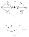
- nodes A to H are nodes in a ASON network, and a service is transmitted between the node A and the node H via the connection of the 1 + 1 revertive protection mode.
- the intermediate nodes of a working path 101 are nodes C and E; the intermediate nodes of a protection path 102 are nodes D and G.
- the node H selects the service transmitted via the protection path 102.
- the control plane calculates a restoration path and establishes a restoration path 103 as calculated by using signaling, and the intermediate nodes of the restoration path are the nodes B and F, so that the service is transmited normally and the 1+1 protection is implemented.
- the node C sends an alarm disappearance message to notify all head nodes of connections including the link that the failure is recovered, i.e. notifiy the head node A of the working path 101 in Figure 1 that the failure is recovered.
- the node A switches the service from the protection path 102 back to the original working path 101 and delets the restoration path 103.
- the WTR time is set for preventing frequent switchings of the service between the working path 101 and the restoration path 103 caused by the instability of the working path.
- the inventor through in-depth researches, finds that by using the service switching of the conventional mode, if the number of connections including a link is large, a great number of alarm messages may be caused when the link fails, and a great deal of information is transmitted. Further, by using the service switching of the conventional mode, when parts of sources are shared by a protection path and an original working path, the revertive processing can not be implemented. For example, if the protection of a link transmitting a serivice is a multiplex-section protection, when the failure of the link is recovered, whether the service switching needs to be performed can not be determined only according to the alarm disappearance.
- the present invention provides embodiments of a method for switching a service so as to switch a service independent of alarm messages.
- the embodiments may be used in networks in which a service switches to a protection path when a working path fails, and the method includes the following processes:
- the end node of the service is the head node or the tail node of the working path.
- the method further includes:
- the method further includes:
- the method further includes: deleting connections of the restoration path, the connections being separate from the working path.
- the method further includes: configuring a wait to restore timer in the end node; determining whether the working path fails before the wait to restore timer expires; if yes, terminating the method; otherwise, performing the subsequent processes.
- the network is an Automatic Switched Optical Network, ASON.
- the mode of detecting the change in the topology of the network includes: updating a Routing message Data Base, RDB, on receipt of flooding information of the Open Shortest Path First-Traffic Engineering, OSPF-TE, protocol; and determining that the topology of the network changes when contents of the RDB change.
- RDB Routing message Data Base
- the present invention also provides embodiments of a network node including a route controller, a link resource manager and a connection controller.
- the network node further includes a path testing unit, configured to determine whether a working path in a network is restored when the link resource manager inform a change in topology of the network, the network node being an end node of the working path; and send a signal to the route controller if the working path is restored.
- the route controller is configured to send a trigger signal according to the received signal, the connection controller switching the service from the protecting path back to the working path according to the trigger signal.
- the network node further includes a wait to restore timer.
- the path testing unit is further configured to start the wait to restore timer before sending the signal, determine whether the working path fails before the wait to restore timer expires, and send the signal or stop the wait to restore timer if the working path does not fail.
- At least one of the path detecting unit and the timer is located at the route controller.
- the network node is a network node of an Automatically Switched Optical Network, ASON.
- the service switching is triggered according to the change in topology of the network instead of the alarm disappearance. Therefore, the spread of alarm messages decreases.
- the revertive processing is implemented when parts of sources are shared by a protection path and an original working path.
- routing technologies in the ASON are used adequately. Before solutions in the embodiments of the present invention are described in detail, the routing technologies in the ASON are described briefly.
- Figure 2 shows a schematic diagram illustrating the structure of a node in the ASON, and the node includes as follows.
- Routing Controller (RC) 210 is configured to respond to the request for channel or routing information which is sent by a connection controller for establishing a connection. Routing Controller 210 is also configured to exchange routing information with peer Routing Controllers, and answer the inquiry of routing information after inquiring Routing Data Base (RDB) 202. Routing Controller 210 is further configured to send topology information required for managing the network, and the topology information includes Sub Network Points (SNPs) and the attribute of the SNPs.
- SNPs Sub Network Points
- Routing Data Base (RDB) 220 is configured to provide Route Controller 210 with the routing information, and the routing information may include local topology, network topology, accessibility, routing strategy configuration and other information acquired by exchanging the routing information. Routing Data Base 220 may include routing information of multiple routing domains.
- Link Resource Manager (LRM) 230 is configured to provide Routing Controller 210 with routing information of all SNP Pool (SNPP), and inform Routing Controller 210 about any changes in states of link resources controlled by Link Resource Manager 230.
- SNPP SNP Pool
- Protocol Controller (PC) 240 is configured to convert a routing primitive into a message of a specific routing protocol, and Protocol Controller 240 is related to the protocol. Protocol Controller 240 is also configured to process control information related to routing protocols, and the control information is used for managing and maintaining exchange of the routing information.
- Connection Controller 250 is configured to establish a connection according to the instruction from Routing Controller210.
- OSPF-TE Open Shortest Path First-Traffic Extension
- ASON GMPLS-based Open Shortest Path First-Traffic Extension
- OSPF-TE Open Shortest Path First-Traffic Extension
- a network node may quickly perceive the change in topology of the network, e.g., routing interface fails.
- the Routing Data Base of each network node is synchronized by sending the Link Status Announcement (LSA) between adjacent nodes, i.e., all network nodes have the same topology information and link information eventually. In this way, each network node may perceive the change in topology of the network.
- LSA Link Status Announcement
- the embodiment of the present invention includes the following process.
- the control plane When a working path M1 used for transmitting a service fails, the control plane performs a dynamic restoration and establishes a path M2, and then the service is transmitted via the path M2.
- the end node checks whether all the links of the original working path M1 are restored according to the routing information in a local RDB; if all the links are restored, a timer is set and the duration of the timer is the WTR time. When the timer expires, the service transmitted by the path M2 is switched back to the working path M1, and the connection of the path M2 is deleted.
- the end node of the service may be the head node or the tail node of the working path M1, and may also be the head node or the tail node of the path M2.
- Embodiments are described as follows according to the two types.
- the method for switching a service is described, and in the method, the links of a restoration path and an original working path are separate except for the head and tail nodes.
- Figure 3 shows a method for switching a service in the 1+1 protection mode, and the network structure shown in Figure 1 is taken as an example.
- the method includes the following processes.
- the tail node H selects the service from the protection path 102.
- the control plane reroutes and establishes a restoration path 103, and the link of the restoration path 103 entirely separate from that of the working path 101.
- the route controller of each node updates self-owned RDB and perceives the change in topology of the network.
- the route controllers of the head and tail nodes of the working path 101 i.e., the node A and the node H, according to the local RDB, checks whether the working path 101 is restored and whether the connection is revertive; if yes, block 304 is performed; otherwise, the process is terminated.
- the node A starts a timer the duration of which is the WTR time. Before the timer expires, the node A determine whether the working path 101 fails again; if yes, the process is terminated; otherwise, block 305 is performed.
- the route controller of the node A triggers a connection controller, and the service is switched from the restoration path 103 to the working path 101.
- the node A sends a deleting message (e.g., Path Tear) to the nodes on the restoration path 103 hop by hop, and deletes the direct-reverse cross connection of the path 103.
- the deleting may be performed according to the process of deleting connection in the standard GMPLS RSVP-TE (with reference of RFC 3473). The process is terminated after the deleting is performed.
- the method for switching a service is described, and in the method, part of resources is shared by a restoration path and an original working path.
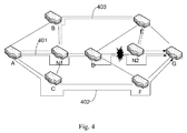
- the working path 401 starts from the head node A to the tail node G through the node N1, the node D and the node N2.
- the intermediate nodes of the protection path include the node C and the node F.
- the restoration path 403 starts from the head node A to the tail node G through the node N1, the node B, the node E and the node N2.
- the connection resources of the working path 401 are shared by the restoration path 403, and the shared connections include the connection between the node A and the node N1 and that between the node N2 and the node G.
- Figure 5 shows a method for switching a service
- the network structure shown in Figure 4 is taken as an example.
- the method includes the following processes.
- the tail node G selects the service from the protection path 402.
- the control plane reroutes, and establishes a restoration path 403 which shares parts of resources with the working path 401.
- the route controller of each node updates self-owned RDB and perceives the change in topology of the network.
- the route controllers of the head and the tail nodes of the working path 401 i.e., the node A and the node G, according to the local RDB, check whether the working path 401 is restored and whether the connection is revertive; if yes, block 504 is performed; otherwise, the process is terminated.
- the node A starts a timer the duration of which is the WTR time. Before the timer expires, the node A determines whether the working path 401 fails again; if yes, the process is terminated; otherwise, block 505 is performed.
- the route controller of the node A triggers a connection controller, and the service is switched from the restoration path 403 to the working path 401.
- the node A sends a deleting message to the nodes of the restoration path 403, and deletes the connection separate from the working path 401, i.e., deletes the connection from the node N1 to the node B, from the node B to the node E, and from the node E to the node N2, and retains the shared connections of the working path 401, i.e., the connections from the node A to the node N1, and the node N2 to the node G.
- the deleting may be performed according to the process of deleting connection in the standard GMPLS RSVP-TE (with reference of RFC 3473). The process is terminated after the deleting is performed.
- Each operation performed by the head node of the working path i.e. the node A in the above blocks 504 to 506 may also be performed by the tail node of the working path, i.e., the node G.
- the method for switching a service is described, and in the method, the working path does not have a preconfigured protection path, and a path may be configured when the working path fails.
- the working paths are in the 1 + 1 protection mode.
- the solution of the present invention may also be used when the working paths have no protection.
- data is transmitted from the head node A to the tail node H via the working path 601.
- a protection path 602 is established, and then the data is transmitted via the protection path 602.
- the head node A or the tail node H learns that the working path 601 is restored by perceiving the change in topology of the network, a timer is started, and the duration of the timer is the WTR time. When the timer expires, the service is switched back to the working path 601, and the protection path 602 is deleted.
- the protection path 602 and the working path 601 are separate from each other except for the head and tail nodes.
- part of connections may be shared by the protection path 602 and the working path 601. In this way, when the protection path 602 is deleted, the connections of the protection path 602 are deleted, and the connections are separate from the working path 603.
- Figure 7 shows a schematic diagram of a network node for implementing the method in the embodiment of the present invention.
- a Path Testing Unit 711 and a WTR Timer 712 are added in the Route Controller 710 of the network node.
- the Path Testing Unit 711 is configured to, when the Link Resource Manager 730 reports the change in topology of the network, determine whether a working path is restored to a normal state from a failure state before the topology of the network changes, the head node of the working path being the network node, the working path being revertive. Path Testing Unit 711 is further configured to start the WTR timer 712, and the duration of the WTR timer 712 is the WTR time.
- the Path Detecting Unit 711 is further configured to determine whether the working path fails again; if yes, the WTR Timer 712 is stopped.
- the Path Detecting Unit 711 or the WTR Timer 712 sends a path-return signal to the Route Controller 710.
- the Route Controller 710 on receipt of the signal, triggers the process of switching the service from the protection path to the working path.
- the Path Testing Unit 711 and the WTR Timer 712 may also be configured as modules in the network node, and the modules and the Route Controller 719 are independent with each other.
- An interface towards the Connection Controller 750 may also be added in the Route Controller 710 for triggering the Connection Controller 750, and then the Connection Controller 750 switches the service from the protection path to the working path, delete the protection path or delete the connections of the restoration path which is separate from the working path.
- the service switching is triggered according to the change in topology of the network. Therefore, the spread of alarm messages is curbed.
- the revertive processing is implemented when part of sources is shared by a protection path and an original working path, and the embodiments of the present invention may implement the revertive processing of various protection modes.
Abstract
Description
- The present invention relates to Automatically Switched Optical Network (ASON) technologies, and more particularly, to a method and a network node for switching a service.
- Along with the development of information technologies, particularly Internet techonlogies which effectively stimulate the growth of data services, the requirements of optical networks include: dynamically adjusting the logic topology of a network in real time, optimally utilizing resources, quickly providing for users with various high-quality services and applications of bandwidth, having better protection and restoration functions and better interoperability and expansibility. But in traditional optical networks, service scheduling is statically configured by a network manager, and services can not be dynamically activated. Further in the traditional optical networks, linear or ring networkings are widely used, and static restoration methods are utilized for protection restoration including the multiplex section protection, Sub-Network Connection Protection (SNCP) and Passage Protect (PP) etc. Therefore, the traditional optical network can not satisfy the above demand.
- For the purpose of satisfying the demand of services, the International Telecommunication Unite-T sector (ITU-T), the Internet Engineering Task Force (IETF) and the Optical Internetworking Forum (OIF) jointly develop Automatically Switched Optical Network (ASON) technologies which may well solve the above problem. The ASON introduces intelligentization of switching to provide dynamic end-to-end connection which may support mesh network structures, and the size of bandwidth may be configured as required. Therefore, the survivability of the network greatly improves, expansion capacities of the network are flexible and protection restoration functions of the network are fast.
- The main difference between the ASON and the traditional optical transport network includes that a control plane is introduced so as to evolve the management architecture of the traditional optical transport network into a multi-plane management architecture of a new type based on a management plane, a control plane and a transport plane. The Generalized Multi-Protocol Label Switching (GMPLS) protocol is used in the control plane, and services are established by Switched Connections (SC) and Soft Permanent Connections (SPC). By the functions of the control plane, the whole end-to-end connections or part of the end-to-end connections may be established, maintained and deleted automatically within a short time. When the working path of a service fails, the control plane, by the GMPLS signaling protocol, quickly performs a re-routing, establishs a protection path, and transmits the service via the established protection path so as to transmit the service normally. After the original working path is restored, the service may be switched from the protection path to the original working path, so that the management of the network is flexible for the operator, and the routing of network connections may change temporally and dynamically and may keep stable at most of the time. Therefore, the characteristic of service switching becomes an important feature in the ASON network.
- In the conventional ASON, whether the original working path is restored is determined according to alarm disappearance and Wait To Restore (WTR) time. If the original working path is restored, an operation of service switching is performed. The operation is described as follows by taking an 1 + 1 revertive protection mode as an example. As shown in
Figure. 1 , nodes A to H are nodes in a ASON network, and a service is transmitted between the node A and the node H via the connection of the 1 + 1 revertive protection mode. The intermediate nodes of a workingpath 101 are nodes C and E; the intermediate nodes of aprotection path 102 are nodes D and G. When the path between the nodes C and E fails, i.e. theworking path 101 fails, the node H selects the service transmitted via theprotection path 102. Meanwhile, the control plane calculates a restoration path and establishes arestoration path 103 as calculated by using signaling, and the intermediate nodes of the restoration path are the nodes B and F, so that the service is transmited normally and the 1+1 protection is implemented. After the failure between the nodes C and E is recovered, the node C sends an alarm disappearance message to notify all head nodes of connections including the link that the failure is recovered, i.e. notifiy the head node A of theworking path 101 inFigure 1 that the failure is recovered. After waiting for a WTR time, the node A switches the service from theprotection path 102 back to the original workingpath 101 and delets therestoration path 103. The WTR time is set for preventing frequent switchings of the service between the workingpath 101 and therestoration path 103 caused by the instability of the working path. - However, the inventor, through in-depth researches, finds that by using the service switching of the conventional mode, if the number of connections including a link is large, a great number of alarm messages may be caused when the link fails, and a great deal of information is transmitted. Further, by using the service switching of the conventional mode, when parts of sources are shared by a protection path and an original working path, the revertive processing can not be implemented. For example, if the protection of a link transmitting a serivice is a multiplex-section protection, when the failure of the link is recovered, whether the service switching needs to be performed can not be determined only according to the alarm disappearance.
- The present invention provides embodiments of a method for switching a service so as to switch a service independent of alarm messages. The embodiments may be used in networks in which a service switches to a protection path when a working path fails, and the method includes the following processes:
- determining whether the working path is restored when an end node of the service detects a change in topology of the network; and switching the service from the protection path back to the working path when the working path is restored, otherwise terminating the method.
- The end node of the service is the head node or the tail node of the working path.
- Before the service is switched to the protection path, the method further includes:
- configuring the protection path, the end nodes of the protection path being the end nodes of the working path;
after switching the service from the protection path back to the working path, the method further includes: deleting connections of the protection path, the connections being separate from the working path. - After the service is switched to the protection path, the method further includes:
- establishing a restoration path, the end nodes of the restoration path being the end nodes of the working path.
- After switching the service from the protection path back to the working path, the method further includes: deleting connections of the restoration path, the connections being separate from the working path.
- Before switching the service from the protection path back to the working path , the method further includes: configuring a wait to restore timer in the end node; determining whether the working path fails before the wait to restore timer expires; if yes, terminating the method; otherwise, performing the subsequent processes.
- The network is an Automatic Switched Optical Network, ASON.
- The mode of detecting the change in the topology of the network includes: updating a Routing message Data Base, RDB, on receipt of flooding information of the Open Shortest Path First-Traffic Engineering, OSPF-TE, protocol; and determining that the topology of the network changes when contents of the RDB change.
- The present invention also provides embodiments of a network node including a route controller, a link resource manager and a connection controller. The network node further includes a path testing unit, configured to determine whether a working path in a network is restored when the link resource manager inform a change in topology of the network, the network node being an end node of the working path; and send a signal to the route controller if the working path is restored.
The route controller is configured to send a trigger signal according to the received signal, the connection controller switching the service from the protecting path back to the working path according to the trigger signal. - Preferably, the network node further includes a wait to restore timer.
The path testing unit is further configured to start the wait to restore timer before sending the signal, determine whether the working path fails before the wait to restore timer expires, and send the signal or stop the wait to restore timer if the working path does not fail. - At least one of the path detecting unit and the timer is located at the route controller.
- The network node is a network node of an Automatically Switched Optical Network, ASON.
- It can be seen from the above solution that in the embodiments of the present invention, the service switching is triggered according to the change in topology of the network instead of the alarm disappearance. Therefore, the spread of alarm messages decreases. Moreover, by using the embodiment of the present invention, the revertive processing is implemented when parts of sources are shared by a protection path and an original working path.
-
-
Figure 1 is a schematic diagram illustrating a network of a 1 + 1 protection mode in which the link of a working path and that of a restoration path are independent. -
Figure 2 is a schematic diagram illustrating a structure of a conventional network node. -
Figure 3 is a flowchart illustrating a method for switching a service in accordance with an embodiment of the present invention. -
Figure 4 is a schematic diagram illustrating a network of the 1+1 protection mode in which part of links are shared by a restoration path and a working path. -
Figure 5 is a flowchart illustrating a method for switching a service in accordance with another embodiment of the present invention. -
Figure 6 is a schematic diagram illustrating a network including working paths without protection in accordance with another embodiment of the present invention. -
Figure 7 is a schematic diagram illustrating a structure of an ASON network node in accordance with another embodiment of the present invention. - In the embodiments of the present invention, the characteristics of routing technologies in the ASON are used adequately. Before solutions in the embodiments of the present invention are described in detail, the routing technologies in the ASON are described briefly.
-
Figure 2 shows a schematic diagram illustrating the structure of a node in the ASON, and the node includes as follows. - Routing Controller (RC) 210 is configured to respond to the request for channel or routing information which is sent by a connection controller for establishing a connection. Routing Controller 210 is also configured to exchange routing information with peer Routing Controllers, and answer the inquiry of routing information after inquiring Routing Data Base (RDB) 202. Routing Controller 210 is further configured to send topology information required for managing the network, and the topology information includes Sub Network Points (SNPs) and the attribute of the SNPs.
- Routing Data Base (RDB) 220 is configured to provide Route Controller 210 with the routing information, and the routing information may include local topology, network topology, accessibility, routing strategy configuration and other information acquired by exchanging the routing information. Routing Data Base 220 may include routing information of multiple routing domains.
- Link Resource Manager (LRM) 230 is configured to provide Routing Controller 210 with routing information of all SNP Pool (SNPP), and inform Routing Controller 210 about any changes in states of link resources controlled by Link Resource Manager 230.
- Protocol Controller (PC) 240 is configured to convert a routing primitive into a message of a specific routing protocol, and Protocol Controller 240 is related to the protocol. Protocol Controller 240 is also configured to process control information related to routing protocols, and the control information is used for managing and maintaining exchange of the routing information.
- Connection Controller 250 is configured to establish a connection according to the instruction from Routing Controller210.
- GMPLS-based Open Shortest Path First-Traffic Extension (OSPF-TE) protocol is adopted as the routing information distribution protocol of the ASON. By the OSPF-TE protocol, a network node may quickly perceive the change in topology of the network, e.g., routing interface fails. By flooding mechanisms, the Routing Data Base of each network node is synchronized by sending the Link Status Announcement (LSA) between adjacent nodes, i.e., all network nodes have the same topology information and link information eventually. In this way, each network node may perceive the change in topology of the network.
- According to the above characteristics of the routing technologies of the ASON, the embodiment of the present invention includes the following process.
- When a working path M1 used for transmitting a service fails, the control plane performs a dynamic restoration and establishes a path M2, and then the service is transmitted via the path M2.
- If an end node of the service perceives the change in topology of the network, the end node checks whether all the links of the original working path M1 are restored according to the routing information in a local RDB; if all the links are restored, a timer is set and the duration of the timer is the WTR time. When the timer expires, the service transmitted by the path M2 is switched back to the working path M1, and the connection of the path M2 is deleted.
- The end node of the service may be the head node or the tail node of the working path M1, and may also be the head node or the tail node of the path M2.
- There are two types of the established path M2:
- (1) the links of M1 and M2 are separate except for the head and tail nodes;
- (2) part of resources are shared by M2 and M1, i.e., part of normal connections of the original M1 are reused.
- Embodiments are described as follows according to the two types.
- In the first embodiment, the method for switching a service is described, and in the method, the links of a restoration path and an original working path are separate except for the head and tail nodes.
-
Figure 3 shows a method for switching a service in the 1+1 protection mode, and the network structure shown inFigure 1 is taken as an example. The method includes the following processes. - At
block 301, when the link between the node C and the node E fails, i.e., when the workingpath 101 fails, the tail node H selects the service from theprotection path 102. The control plane reroutes and establishes arestoration path 103, and the link of therestoration path 103 entirely separate from that of the workingpath 101. - At
block 302, when the failure of the link between the node C and the node E is recovered, i.e., the workingpath 101 is restored, by the flooding mechanisms of the OSPF-TE, the route controller of each node updates self-owned RDB and perceives the change in topology of the network. - At
block 303, after perceiving the change in topology of the network, the route controllers of the head and tail nodes of the workingpath 101, i.e., the node A and the node H, according to the local RDB, checks whether the workingpath 101 is restored and whether the connection is revertive; if yes, block 304 is performed; otherwise, the process is terminated. - At
block 304, the node A starts a timer the duration of which is the WTR time. Before the timer expires, the node A determine whether the workingpath 101 fails again; if yes, the process is terminated; otherwise, block 305 is performed. - At
block 305, after the timer expires, the route controller of the node A triggers a connection controller, and the service is switched from therestoration path 103 to the workingpath 101. - At
block 306, the node A sends a deleting message (e.g., Path Tear) to the nodes on therestoration path 103 hop by hop, and deletes the direct-reverse cross connection of thepath 103. The deleting may be performed according to the process of deleting connection in the standard GMPLS RSVP-TE (with reference of RFC 3473). The process is terminated after the deleting is performed. - In the second embodiment, the method for switching a service is described, and in the method, part of resources is shared by a restoration path and an original working path.
- As shown in
Figure 4 , in the 1+1 protection mode, the workingpath 401 starts from the head node A to the tail node G through the node N1, the node D and the node N2. The intermediate nodes of the protection path include the node C and the node F. Therestoration path 403 starts from the head node A to the tail node G through the node N1, the node B, the node E and the node N2. The connection resources of the workingpath 401 are shared by therestoration path 403, and the shared connections include the connection between the node A and the node N1 and that between the node N2 and the node G. -
Figure 5 shows a method for switching a service, and the network structure shown inFigure 4 is taken as an example. The method includes the following processes. - At block 501, when the link between the node D and the node N2 fails, i.e., when the working
path 401 fails, the tail node G selects the service from theprotection path 402. The control plane reroutes, and establishes arestoration path 403 which shares parts of resources with the workingpath 401. - At block 502, when the failure of the link between the node D and the node N2 is recovered, i.e., the working
path 401 is restored, by the flooding mechanisms of the OSPF-TE, the route controller of each node updates self-owned RDB and perceives the change in topology of the network. - At block 503, after perceiving the change in topology of the network, the route controllers of the head and the tail nodes of the working
path 401, i.e., the node A and the node G, according to the local RDB, check whether the workingpath 401 is restored and whether the connection is revertive; if yes, block 504 is performed; otherwise, the process is terminated. - At block 504, the node A starts a timer the duration of which is the WTR time. Before the timer expires, the node A determines whether the working
path 401 fails again; if yes, the process is terminated; otherwise, block 505 is performed. - At block 505, after the timer expires, the route controller of the node A triggers a connection controller, and the service is switched from the
restoration path 403 to the workingpath 401. - At block 506, the node A sends a deleting message to the nodes of the
restoration path 403, and deletes the connection separate from the workingpath 401, i.e., deletes the connection from the node N1 to the node B, from the node B to the node E, and from the node E to the node N2, and retains the shared connections of the workingpath 401, i.e., the connections from the node A to the node N1, and the node N2 to the node G. The deleting may be performed according to the process of deleting connection in the standard GMPLS RSVP-TE (with reference of RFC 3473). The process is terminated after the deleting is performed. - Each operation performed by the head node of the working path, i.e. the node A in the above blocks 504 to 506 may also be performed by the tail node of the working path, i.e., the node G.
- In the third embodiment 3, the method for switching a service is described, and in the method, the working path does not have a preconfigured protection path, and a path may be configured when the working path fails.
- In the above two embodiments for switching the service, the working paths are in the 1 + 1 protection mode. The solution of the present invention may also be used when the working paths have no protection. As shown in
Figure 6 , data is transmitted from the head node A to the tail node H via the workingpath 601. When the link between an intermediate node C and a node E fails in the transmission, aprotection path 602 is established, and then the data is transmitted via theprotection path 602. If the head node A or the tail node H learns that the workingpath 601 is restored by perceiving the change in topology of the network, a timer is started, and the duration of the timer is the WTR time. When the timer expires, the service is switched back to the workingpath 601, and theprotection path 602 is deleted. - In
Figure 6 , theprotection path 602 and the workingpath 601 are separate from each other except for the head and tail nodes. In practice, part of connections may be shared by theprotection path 602 and the workingpath 601. In this way, when theprotection path 602 is deleted, the connections of theprotection path 602 are deleted, and the connections are separate from the working path 603. -
Figure 7 shows a schematic diagram of a network node for implementing the method in the embodiment of the present invention. By comparison with the conventional network node, in the embodiment of the present invention, aPath Testing Unit 711 and aWTR Timer 712 are added in theRoute Controller 710 of the network node. - The
Path Testing Unit 711 is configured to, when theLink Resource Manager 730 reports the change in topology of the network, determine whether a working path is restored to a normal state from a failure state before the topology of the network changes, the head node of the working path being the network node, the working path being revertive.Path Testing Unit 711 is further configured to start theWTR timer 712, and the duration of theWTR timer 712 is the WTR time. - Before the
WTR Timer 712 expires, thePath Detecting Unit 711 is further configured to determine whether the working path fails again; if yes, theWTR Timer 712 is stopped. - When the
WTR Timer 712 expires, thePath Detecting Unit 711 or theWTR Timer 712 sends a path-return signal to theRoute Controller 710. TheRoute Controller 710, on receipt of the signal, triggers the process of switching the service from the protection path to the working path. - The
Path Testing Unit 711 and theWTR Timer 712 may also be configured as modules in the network node, and the modules and the Route Controller 719 are independent with each other. - An interface towards the
Connection Controller 750 may also be added in theRoute Controller 710 for triggering theConnection Controller 750, and then theConnection Controller 750 switches the service from the protection path to the working path, delete the protection path or delete the connections of the restoration path which is separate from the working path. - In the embodiments of the present invention, other modules of the ASON network node are the same as that of the conventional ASON network node, and no further description is given.
- In the solution of the embodiment of the present invention, the service switching is triggered according to the change in topology of the network. Therefore, the spread of alarm messages is curbed. Moreover, the revertive processing is implemented when part of sources is shared by a protection path and an original working path, and the embodiments of the present invention may implement the revertive processing of various protection modes.
- The above is only preferred embodiments of the present invention and is not for use in limiting the present invention. Any modification, equivalent replacement or improvement made under the principles of the present invention shall be included in the protection scope of the present invention.
Claims (12)
- A method for switching a service, applied to a network in which a service switches to a protection path when a working path fails, comprising:determining whether the working path is restored when an end node of the service detects a change in topology of the network; and switching the service from the protection path back to the working path when the working path is restored, otherwise the method is terminated.
- The method of Claim 1, wherein the end node of the service is the head node or the tail node of the working path.
- The method of Claim 1, before the service is switched to the protection path further comprising: configuring the protection path, the end nodes of the protection path being the end nodes of the working path;
after switching the service from the protection path back to the working path further comprising: deleting connections of the protection path, the connections being separate from the working path. - The method of Claim 1, after the service is switched to the protection path further comprising: establishing a restoration path, the end nodes of the restoration path being the end nodes of the working path.
- The method of Claim 4, after switching the service from the protection path back to the working path further comprising: deleting connections of the restoration path, the connections being separate from the working path.
- The method of Claim 1, before switching the service from the protection path back to the working path further comprising: configuring a wait to restore timer in the end node; determining whether the working path fails before the wait to restore timer expires; if yes, the method is terminate; otherwise, the subsequent processes are performed.
- The method of any of Claims 1 to 6, wherein the network is an Automatic Switched Optical Network, ASON.
- The method of any of Claims 1 to 6, wherein detecting the change in the topology of the network comprises: updating a Routing message Data Base, RDB, on receipt of flooding information of the Open Shortest Path First-Traffic Engineering, OSPF-TE, protocol; and determining that the topology of the network changes when contents of the RDB change.
- A network node for switching a service, comprising: a route controller, a link resource manager and a connection controller, wherein the network node further comprising a path testing unit, configured to determine whether a working path in a network is restored when the link resource manager inform a change in topology of the network, the network node being an end node of the working path; and send a signal to the route controller if the working path is restored; wherein
the route controller is configured to send a trigger signal according to the received signal, the connection controller switching the service from the protecting path back to the working path according to the trigger signal. - The network node of Claim 9, further comprising: a wait to restore timer; wherein
the path testing unit is further configured to start the wait to restore timer before sending the signal, determine whether the working path fails before the wait to restore timer expires, and send the signal or stop the wait to restore timer if the working path does not fail. - The network node of Claim 10, wherein at least one of the path detecting unit and the timer is located at the route controller.
- The network node of any of Claims 9 to 11, wherein the network node is a network node of an Automatically Switched Optical Network, ASON.
Applications Claiming Priority (2)
| Application Number | Priority Date | Filing Date | Title |
|---|---|---|---|
| CNA2006100785430A CN101047440A (en) | 2006-05-10 | 2006-05-10 | Method of service route return |
| PCT/CN2006/003474 WO2007128176A1 (en) | 2006-05-10 | 2006-12-18 | A service switching method and the network node thereof |
Publications (3)
| Publication Number | Publication Date |
|---|---|
| EP1942604A1 true EP1942604A1 (en) | 2008-07-09 |
| EP1942604A4 EP1942604A4 (en) | 2009-03-25 |
| EP1942604B1 EP1942604B1 (en) | 2013-02-20 |
Family
ID=38667403
Family Applications (1)
| Application Number | Title | Priority Date | Filing Date |
|---|---|---|---|
| EP06828385A Active EP1942604B1 (en) | 2006-05-10 | 2006-12-18 | A service switching method and the network node thereof |
Country Status (3)
| Country | Link |
|---|---|
| EP (1) | EP1942604B1 (en) |
| CN (2) | CN101047440A (en) |
| WO (1) | WO2007128176A1 (en) |
Cited By (7)
| Publication number | Priority date | Publication date | Assignee | Title |
|---|---|---|---|---|
| EP2187582A1 (en) * | 2008-11-12 | 2010-05-19 | Nec Corporation | Transmission apparatus, transmission network, and method being employed thereof |
| CN101990133A (en) * | 2009-07-31 | 2011-03-23 | 中兴通讯股份有限公司 | Maintenance method and system for degradation alarm status of automatically switched optical network service |
| RU2479943C1 (en) * | 2009-08-10 | 2013-04-20 | Зти Корпорейшн | Method and apparatus for sub-network connection protection service migration |
| US9071513B2 (en) | 2010-11-19 | 2015-06-30 | Zte Corporation | Path switch-back method and apparatus in transport network |
| EP2466793A4 (en) * | 2009-08-13 | 2016-04-20 | Zte Corp | Method and device for protecting network |
| CN106789634A (en) * | 2016-11-17 | 2017-05-31 | 深圳市深信服电子科技有限公司 | Static routing management method and system based on the double primary climates of link load |
| CN106789627A (en) * | 2016-11-30 | 2017-05-31 | 瑞斯康达科技发展股份有限公司 | A kind of maintaining method and device of linear protection group |
Families Citing this family (13)
| Publication number | Priority date | Publication date | Assignee | Title |
|---|---|---|---|---|
| CN101466051B (en) * | 2007-12-21 | 2011-06-08 | 华为技术有限公司 | Method and apparatus for searching business route |
| CN101616344B (en) * | 2009-06-17 | 2012-06-06 | 中兴通讯股份有限公司 | Method and device for protecting service based on automatic exchange optical network |
| WO2012163242A1 (en) * | 2011-06-03 | 2012-12-06 | 中兴通讯股份有限公司 | Method and device for service to return to initial route |
| CN105141520A (en) * | 2014-05-28 | 2015-12-09 | 中兴通讯股份有限公司 | Protection switching method, device and system |
| CN104935507B (en) * | 2015-06-03 | 2018-05-08 | 瑞斯康达科技发展股份有限公司 | A kind of method of linear protection switching, PE equipment and system |
| CN106330294A (en) * | 2015-06-18 | 2017-01-11 | 中兴通讯股份有限公司 | Business control method and device in optical communication network |
| CN104881759A (en) * | 2015-06-23 | 2015-09-02 | 四川久远银海软件股份有限公司 | Business fallback integrated system based on workflow and realization method thereof |
| CN105871452B (en) * | 2016-05-24 | 2018-04-20 | 烽火通信科技股份有限公司 | A kind of method of primary channel part path resource-sharing in ASON |
| CN107579914A (en) * | 2016-07-04 | 2018-01-12 | 中兴通讯股份有限公司 | A kind of apparatus and method for quickly robbing logical business route |
| CN110121857B (en) * | 2016-12-30 | 2021-02-09 | 华为技术有限公司 | Credential distribution method and device |
| CN107395425A (en) * | 2017-07-31 | 2017-11-24 | 烽火通信科技股份有限公司 | A kind of flexibly Ethernet 1+1 protection switches implementation method |
| CN112910781B (en) * | 2019-12-04 | 2022-12-06 | 中国电信股份有限公司 | Network fault switching method, device, system and storage medium |
| CN113849361B (en) * | 2021-09-28 | 2023-08-08 | 北京百度网讯科技有限公司 | Method, device, equipment and storage medium for testing service node |
Citations (2)
| Publication number | Priority date | Publication date | Assignee | Title |
|---|---|---|---|---|
| US20020167898A1 (en) * | 2001-02-13 | 2002-11-14 | Thang Phi Cam | Restoration of IP networks using precalculated restoration routing tables |
| US20030117950A1 (en) * | 2001-12-26 | 2003-06-26 | Huang Gail G | Link redial for mesh protection |
Family Cites Families (3)
| Publication number | Priority date | Publication date | Assignee | Title |
|---|---|---|---|---|
| US6757258B1 (en) * | 2000-05-04 | 2004-06-29 | Cisco Technology, Inc. | Method and apparatus for reducing OSPF flooding |
| US7525907B2 (en) * | 2002-07-05 | 2009-04-28 | Nortel Networks Limited | Method, device and software for establishing protection paths on demand and revertive protection switching in a communications network |
| CN100369419C (en) * | 2005-07-14 | 2008-02-13 | 广东省电信有限公司研究院 | Method for realizing connected reinforced main-apparatus protection in automatic exchange optical network |
-
2006
- 2006-05-10 CN CNA2006100785430A patent/CN101047440A/en active Pending
- 2006-12-18 WO PCT/CN2006/003474 patent/WO2007128176A1/en active Application Filing
- 2006-12-18 EP EP06828385A patent/EP1942604B1/en active Active
- 2006-12-18 CN CNA2006800114985A patent/CN101176303A/en active Pending
Patent Citations (2)
| Publication number | Priority date | Publication date | Assignee | Title |
|---|---|---|---|---|
| US20020167898A1 (en) * | 2001-02-13 | 2002-11-14 | Thang Phi Cam | Restoration of IP networks using precalculated restoration routing tables |
| US20030117950A1 (en) * | 2001-12-26 | 2003-06-26 | Huang Gail G | Link redial for mesh protection |
Non-Patent Citations (2)
| Title |
|---|
| MARKO LUOMA: "S-38.192 Network Service Provisioning, Lecture 10, Resiliency"[Online] 12 April 2005 (2005-04-12), XP002513327 Retrieved from the Internet: URL:http://www.netlab.tkk.fi/opetus/s38192/k2005/slides/L10_handout.pdf> [retrieved on 2009-01-30] * |
| See also references of WO2007128176A1 * |
Cited By (12)
| Publication number | Priority date | Publication date | Assignee | Title |
|---|---|---|---|---|
| EP2187582A1 (en) * | 2008-11-12 | 2010-05-19 | Nec Corporation | Transmission apparatus, transmission network, and method being employed thereof |
| JP2010141879A (en) * | 2008-11-12 | 2010-06-24 | Nec Corp | Transmission apparatus, transmission network, and path switching method being employed therefor |
| CN101990133A (en) * | 2009-07-31 | 2011-03-23 | 中兴通讯股份有限公司 | Maintenance method and system for degradation alarm status of automatically switched optical network service |
| CN101990133B (en) * | 2009-07-31 | 2014-02-19 | 中兴通讯股份有限公司 | Maintenance method and system for degradation alarm status of automatically switched optical network service |
| RU2479943C1 (en) * | 2009-08-10 | 2013-04-20 | Зти Корпорейшн | Method and apparatus for sub-network connection protection service migration |
| US8554073B2 (en) | 2009-08-10 | 2013-10-08 | Zte Corporation | Method and apparatus for migrating sub-network connection protection (SNCP) service |
| EP2466793A4 (en) * | 2009-08-13 | 2016-04-20 | Zte Corp | Method and device for protecting network |
| US9071513B2 (en) | 2010-11-19 | 2015-06-30 | Zte Corporation | Path switch-back method and apparatus in transport network |
| CN106789634A (en) * | 2016-11-17 | 2017-05-31 | 深圳市深信服电子科技有限公司 | Static routing management method and system based on the double primary climates of link load |
| CN106789634B (en) * | 2016-11-17 | 2020-06-26 | 深信服科技股份有限公司 | Static route management method and system based on link load dual-main environment |
| CN106789627A (en) * | 2016-11-30 | 2017-05-31 | 瑞斯康达科技发展股份有限公司 | A kind of maintaining method and device of linear protection group |
| CN106789627B (en) * | 2016-11-30 | 2019-11-01 | 瑞斯康达科技发展股份有限公司 | A kind of maintaining method and device of linear protection group |
Also Published As
| Publication number | Publication date |
|---|---|
| WO2007128176A1 (en) | 2007-11-15 |
| EP1942604A4 (en) | 2009-03-25 |
| EP1942604B1 (en) | 2013-02-20 |
| CN101176303A (en) | 2008-05-07 |
| CN101047440A (en) | 2007-10-03 |
Similar Documents
| Publication | Publication Date | Title |
|---|---|---|
| EP1942604B1 (en) | A service switching method and the network node thereof | |
| US7133358B2 (en) | Failure control unit | |
| US7471625B2 (en) | Fault recovery system and method for a communications network | |
| JP2533998B2 (en) | Automatic fault recovery in packet networks | |
| US8134920B2 (en) | Device and method for correcting a path trouble in a communication network | |
| US7787362B2 (en) | Method and device for recovering a shared mesh network | |
| US20030210705A1 (en) | System and method for distributed resource reservation protocol-traffic engineering (RSVP-TE) hitless restart in multi-protocol label switching (MPLS) network | |
| US20030084367A1 (en) | Fault recovery system and method for a communications network | |
| EP1755240B1 (en) | Method for performing association in automatic switching optical network | |
| EP1921797B1 (en) | Recovery method and apparatus for optical network lsp occuring abnormal delete | |
| US8165016B2 (en) | Method and apparatus for setting communication paths in a network | |
| KR102157711B1 (en) | Methods for recovering failure in communication networks | |
| JP3905218B2 (en) | Synchronous digital hierarchical communication network | |
| CN101155179B (en) | Method for removing ring circuit during multi-protocol label switching | |
| EP2328307B1 (en) | Barrier boundary node and method for establishing connection between barrier bound ary nodes | |
| US20030043427A1 (en) | Method of fast circuit recovery using local restoration | |
| CN112803995B (en) | Resource sharing method, network node and related equipment | |
| US7672331B1 (en) | Method and apparatus for initiating routing messages in a communication network | |
| JP2008103893A (en) | Communication system and fault restoring method | |
| WO2017066923A1 (en) | Method, network controller, and system for establishing service path | |
| KR100288755B1 (en) | Private network network interface routing method for considering connections currently being in progress of setup phase | |
| KR100501320B1 (en) | method for recovery of CR-LSP in Multi Protocol Label Switching system | |
| JP4579917B2 (en) | Method for activating a pre-planned line in a communication network and a network according to the method | |
| Park et al. | Fast Restoration Mechanism through the GMPLS in Optical Networks |
Legal Events
| Date | Code | Title | Description |
|---|---|---|---|
| PUAI | Public reference made under article 153(3) epc to a published international application that has entered the european phase |
Free format text: ORIGINAL CODE: 0009012 |
|
| 17P | Request for examination filed |
Effective date: 20080523 |
|
| AK | Designated contracting states |
Kind code of ref document: A1 Designated state(s): AT BE BG CH CY CZ DE DK EE ES FI FR GB GR HU IE IS IT LI LT LU LV MC NL PL PT RO SE SI SK TR |
|
| RIC1 | Information provided on ipc code assigned before grant |
Ipc: H04L 12/24 20060101AFI20080131BHEP Ipc: H04L 12/56 20060101ALI20090211BHEP |
|
| A4 | Supplementary search report drawn up and despatched |
Effective date: 20090220 |
|
| 17Q | First examination report despatched |
Effective date: 20090423 |
|
| R17C | First examination report despatched (corrected) |
Effective date: 20090514 |
|
| DAX | Request for extension of the european patent (deleted) | ||
| GRAP | Despatch of communication of intention to grant a patent |
Free format text: ORIGINAL CODE: EPIDOSNIGR1 |
|
| RIC1 | Information provided on ipc code assigned before grant |
Ipc: H04L 12/56 20060101AFI20120604BHEP Ipc: H04L 12/24 20060101ALI20120604BHEP Ipc: H04Q 11/00 20060101ALI20120604BHEP |
|
| GRAS | Grant fee paid |
Free format text: ORIGINAL CODE: EPIDOSNIGR3 |
|
| GRAP | Despatch of communication of intention to grant a patent |
Free format text: ORIGINAL CODE: EPIDOSNIGR1 |
|
| REG | Reference to a national code |
Ref country code: DE Ref legal event code: R079 Ref document number: 602006034670 Country of ref document: DE Free format text: PREVIOUS MAIN CLASS: H04L0012240000 Ipc: H04L0012911000 |
|
| GRAA | (expected) grant |
Free format text: ORIGINAL CODE: 0009210 |
|
| AK | Designated contracting states |
Kind code of ref document: B1 Designated state(s): AT BE BG CH CY CZ DE DK EE ES FI FR GB GR HU IE IS IT LI LT LU LV MC NL PL PT RO SE SI SK TR |
|
| REG | Reference to a national code |
Ref country code: GB Ref legal event code: FG4D |
|
| RIC1 | Information provided on ipc code assigned before grant |
Ipc: H04L 12/911 20130101AFI20130115BHEP Ipc: H04L 12/711 20130101ALI20130115BHEP Ipc: H04L 12/751 20130101ALI20130115BHEP Ipc: H04L 12/703 20130101ALI20130115BHEP Ipc: H04L 12/931 20130101ALI20130115BHEP |
|
| REG | Reference to a national code |
Ref country code: CH Ref legal event code: EP |
|
| REG | Reference to a national code |
Ref country code: AT Ref legal event code: REF Ref document number: 597947 Country of ref document: AT Kind code of ref document: T Effective date: 20130315 |
|
| REG | Reference to a national code |
Ref country code: IE Ref legal event code: FG4D |
|
| REG | Reference to a national code |
Ref country code: DE Ref legal event code: R096 Ref document number: 602006034670 Country of ref document: DE Effective date: 20130418 |
|
| REG | Reference to a national code |
Ref country code: AT Ref legal event code: MK05 Ref document number: 597947 Country of ref document: AT Kind code of ref document: T Effective date: 20130220 |
|
| REG | Reference to a national code |
Ref country code: NL Ref legal event code: VDEP Effective date: 20130220 |
|
| REG | Reference to a national code |
Ref country code: LT Ref legal event code: MG4D |
|
| PG25 | Lapsed in a contracting state [announced via postgrant information from national office to epo] |
Ref country code: AT Free format text: LAPSE BECAUSE OF FAILURE TO SUBMIT A TRANSLATION OF THE DESCRIPTION OR TO PAY THE FEE WITHIN THE PRESCRIBED TIME-LIMIT Effective date: 20130220 Ref country code: ES Free format text: LAPSE BECAUSE OF FAILURE TO SUBMIT A TRANSLATION OF THE DESCRIPTION OR TO PAY THE FEE WITHIN THE PRESCRIBED TIME-LIMIT Effective date: 20130531 Ref country code: BG Free format text: LAPSE BECAUSE OF FAILURE TO SUBMIT A TRANSLATION OF THE DESCRIPTION OR TO PAY THE FEE WITHIN THE PRESCRIBED TIME-LIMIT Effective date: 20130520 Ref country code: SE Free format text: LAPSE BECAUSE OF FAILURE TO SUBMIT A TRANSLATION OF THE DESCRIPTION OR TO PAY THE FEE WITHIN THE PRESCRIBED TIME-LIMIT Effective date: 20130220 Ref country code: IS Free format text: LAPSE BECAUSE OF FAILURE TO SUBMIT A TRANSLATION OF THE DESCRIPTION OR TO PAY THE FEE WITHIN THE PRESCRIBED TIME-LIMIT Effective date: 20130620 Ref country code: LT Free format text: LAPSE BECAUSE OF FAILURE TO SUBMIT A TRANSLATION OF THE DESCRIPTION OR TO PAY THE FEE WITHIN THE PRESCRIBED TIME-LIMIT Effective date: 20130220 |
|
| PG25 | Lapsed in a contracting state [announced via postgrant information from national office to epo] |
Ref country code: LV Free format text: LAPSE BECAUSE OF FAILURE TO SUBMIT A TRANSLATION OF THE DESCRIPTION OR TO PAY THE FEE WITHIN THE PRESCRIBED TIME-LIMIT Effective date: 20130220 Ref country code: PT Free format text: LAPSE BECAUSE OF FAILURE TO SUBMIT A TRANSLATION OF THE DESCRIPTION OR TO PAY THE FEE WITHIN THE PRESCRIBED TIME-LIMIT Effective date: 20130620 Ref country code: PL Free format text: LAPSE BECAUSE OF FAILURE TO SUBMIT A TRANSLATION OF THE DESCRIPTION OR TO PAY THE FEE WITHIN THE PRESCRIBED TIME-LIMIT Effective date: 20130220 Ref country code: BE Free format text: LAPSE BECAUSE OF FAILURE TO SUBMIT A TRANSLATION OF THE DESCRIPTION OR TO PAY THE FEE WITHIN THE PRESCRIBED TIME-LIMIT Effective date: 20130220 Ref country code: GR Free format text: LAPSE BECAUSE OF FAILURE TO SUBMIT A TRANSLATION OF THE DESCRIPTION OR TO PAY THE FEE WITHIN THE PRESCRIBED TIME-LIMIT Effective date: 20130521 Ref country code: FI Free format text: LAPSE BECAUSE OF FAILURE TO SUBMIT A TRANSLATION OF THE DESCRIPTION OR TO PAY THE FEE WITHIN THE PRESCRIBED TIME-LIMIT Effective date: 20130220 Ref country code: SI Free format text: LAPSE BECAUSE OF FAILURE TO SUBMIT A TRANSLATION OF THE DESCRIPTION OR TO PAY THE FEE WITHIN THE PRESCRIBED TIME-LIMIT Effective date: 20130220 |
|
| PG25 | Lapsed in a contracting state [announced via postgrant information from national office to epo] |
Ref country code: EE Free format text: LAPSE BECAUSE OF FAILURE TO SUBMIT A TRANSLATION OF THE DESCRIPTION OR TO PAY THE FEE WITHIN THE PRESCRIBED TIME-LIMIT Effective date: 20130220 Ref country code: DK Free format text: LAPSE BECAUSE OF FAILURE TO SUBMIT A TRANSLATION OF THE DESCRIPTION OR TO PAY THE FEE WITHIN THE PRESCRIBED TIME-LIMIT Effective date: 20130220 Ref country code: SK Free format text: LAPSE BECAUSE OF FAILURE TO SUBMIT A TRANSLATION OF THE DESCRIPTION OR TO PAY THE FEE WITHIN THE PRESCRIBED TIME-LIMIT Effective date: 20130220 Ref country code: NL Free format text: LAPSE BECAUSE OF FAILURE TO SUBMIT A TRANSLATION OF THE DESCRIPTION OR TO PAY THE FEE WITHIN THE PRESCRIBED TIME-LIMIT Effective date: 20130220 Ref country code: CZ Free format text: LAPSE BECAUSE OF FAILURE TO SUBMIT A TRANSLATION OF THE DESCRIPTION OR TO PAY THE FEE WITHIN THE PRESCRIBED TIME-LIMIT Effective date: 20130220 Ref country code: RO Free format text: LAPSE BECAUSE OF FAILURE TO SUBMIT A TRANSLATION OF THE DESCRIPTION OR TO PAY THE FEE WITHIN THE PRESCRIBED TIME-LIMIT Effective date: 20130220 |
|
| PG25 | Lapsed in a contracting state [announced via postgrant information from national office to epo] |
Ref country code: CY Free format text: LAPSE BECAUSE OF FAILURE TO SUBMIT A TRANSLATION OF THE DESCRIPTION OR TO PAY THE FEE WITHIN THE PRESCRIBED TIME-LIMIT Effective date: 20130220 |
|
| PLBE | No opposition filed within time limit |
Free format text: ORIGINAL CODE: 0009261 |
|
| STAA | Information on the status of an ep patent application or granted ep patent |
Free format text: STATUS: NO OPPOSITION FILED WITHIN TIME LIMIT |
|
| PG25 | Lapsed in a contracting state [announced via postgrant information from national office to epo] |
Ref country code: IT Free format text: LAPSE BECAUSE OF FAILURE TO SUBMIT A TRANSLATION OF THE DESCRIPTION OR TO PAY THE FEE WITHIN THE PRESCRIBED TIME-LIMIT Effective date: 20130220 |
|
| 26N | No opposition filed |
Effective date: 20131121 |
|
| REG | Reference to a national code |
Ref country code: DE Ref legal event code: R097 Ref document number: 602006034670 Country of ref document: DE Effective date: 20131121 |
|
| REG | Reference to a national code |
Ref country code: CH Ref legal event code: PL |
|
| PG25 | Lapsed in a contracting state [announced via postgrant information from national office to epo] |
Ref country code: MC Free format text: LAPSE BECAUSE OF FAILURE TO SUBMIT A TRANSLATION OF THE DESCRIPTION OR TO PAY THE FEE WITHIN THE PRESCRIBED TIME-LIMIT Effective date: 20130220 Ref country code: LU Free format text: LAPSE BECAUSE OF FAILURE TO SUBMIT A TRANSLATION OF THE DESCRIPTION OR TO PAY THE FEE WITHIN THE PRESCRIBED TIME-LIMIT Effective date: 20131218 |
|
| REG | Reference to a national code |
Ref country code: IE Ref legal event code: MM4A |
|
| PG25 | Lapsed in a contracting state [announced via postgrant information from national office to epo] |
Ref country code: IE Free format text: LAPSE BECAUSE OF NON-PAYMENT OF DUE FEES Effective date: 20131218 Ref country code: LI Free format text: LAPSE BECAUSE OF NON-PAYMENT OF DUE FEES Effective date: 20131231 Ref country code: CH Free format text: LAPSE BECAUSE OF NON-PAYMENT OF DUE FEES Effective date: 20131231 |
|
| PG25 | Lapsed in a contracting state [announced via postgrant information from national office to epo] |
Ref country code: TR Free format text: LAPSE BECAUSE OF FAILURE TO SUBMIT A TRANSLATION OF THE DESCRIPTION OR TO PAY THE FEE WITHIN THE PRESCRIBED TIME-LIMIT Effective date: 20130220 |
|
| PG25 | Lapsed in a contracting state [announced via postgrant information from national office to epo] |
Ref country code: HU Free format text: LAPSE BECAUSE OF FAILURE TO SUBMIT A TRANSLATION OF THE DESCRIPTION OR TO PAY THE FEE WITHIN THE PRESCRIBED TIME-LIMIT; INVALID AB INITIO Effective date: 20061218 |
|
| REG | Reference to a national code |
Ref country code: FR Ref legal event code: PLFP Year of fee payment: 10 |
|
| REG | Reference to a national code |
Ref country code: FR Ref legal event code: PLFP Year of fee payment: 11 |
|
| REG | Reference to a national code |
Ref country code: FR Ref legal event code: PLFP Year of fee payment: 12 |
|
| REG | Reference to a national code |
Ref country code: DE Ref legal event code: R079 Ref document number: 602006034670 Country of ref document: DE Free format text: PREVIOUS MAIN CLASS: H04L0012911000 Ipc: H04L0047700000 |
|
| REG | Reference to a national code |
Ref country code: FR Ref legal event code: PLFP Year of fee payment: 17 |
|
| PGFP | Annual fee paid to national office [announced via postgrant information from national office to epo] |
Ref country code: GB Payment date: 20231102 Year of fee payment: 18 |
|
| PGFP | Annual fee paid to national office [announced via postgrant information from national office to epo] |
Ref country code: FR Payment date: 20231108 Year of fee payment: 18 Ref country code: DE Payment date: 20231031 Year of fee payment: 18 |