EP1944050A2 - Improvements in and relating to drive mechanisms suitable for use in drug delivery devices - Google Patents
Improvements in and relating to drive mechanisms suitable for use in drug delivery devices Download PDFInfo
- Publication number
- EP1944050A2 EP1944050A2 EP08006911A EP08006911A EP1944050A2 EP 1944050 A2 EP1944050 A2 EP 1944050A2 EP 08006911 A EP08006911 A EP 08006911A EP 08006911 A EP08006911 A EP 08006911A EP 1944050 A2 EP1944050 A2 EP 1944050A2
- Authority
- EP
- European Patent Office
- Prior art keywords
- sleeve
- dose dial
- drive sleeve
- housing
- drive
- Prior art date
- Legal status (The legal status is an assumption and is not a legal conclusion. Google has not performed a legal analysis and makes no representation as to the accuracy of the status listed.)
- Granted
Links
- 230000007246 mechanism Effects 0.000 title claims abstract description 49
- 238000012377 drug delivery Methods 0.000 title claims abstract description 38
- 230000006872 improvement Effects 0.000 title description 2
- 229940126601 medicinal product Drugs 0.000 claims abstract description 28
- 230000033001 locomotion Effects 0.000 claims abstract description 17
- NOESYZHRGYRDHS-UHFFFAOYSA-N insulin Chemical compound N1C(=O)C(NC(=O)C(CCC(N)=O)NC(=O)C(CCC(O)=O)NC(=O)C(C(C)C)NC(=O)C(NC(=O)CN)C(C)CC)CSSCC(C(NC(CO)C(=O)NC(CC(C)C)C(=O)NC(CC=2C=CC(O)=CC=2)C(=O)NC(CCC(N)=O)C(=O)NC(CC(C)C)C(=O)NC(CCC(O)=O)C(=O)NC(CC(N)=O)C(=O)NC(CC=2C=CC(O)=CC=2)C(=O)NC(CSSCC(NC(=O)C(C(C)C)NC(=O)C(CC(C)C)NC(=O)C(CC=2C=CC(O)=CC=2)NC(=O)C(CC(C)C)NC(=O)C(C)NC(=O)C(CCC(O)=O)NC(=O)C(C(C)C)NC(=O)C(CC(C)C)NC(=O)C(CC=2NC=NC=2)NC(=O)C(CO)NC(=O)CNC2=O)C(=O)NCC(=O)NC(CCC(O)=O)C(=O)NC(CCCNC(N)=N)C(=O)NCC(=O)NC(CC=3C=CC=CC=3)C(=O)NC(CC=3C=CC=CC=3)C(=O)NC(CC=3C=CC(O)=CC=3)C(=O)NC(C(C)O)C(=O)N3C(CCC3)C(=O)NC(CCCCN)C(=O)NC(C)C(O)=O)C(=O)NC(CC(N)=O)C(O)=O)=O)NC(=O)C(C(C)CC)NC(=O)C(CO)NC(=O)C(C(C)O)NC(=O)C1CSSCC2NC(=O)C(CC(C)C)NC(=O)C(NC(=O)C(CCC(N)=O)NC(=O)C(CC(N)=O)NC(=O)C(NC(=O)C(N)CC=1C=CC=CC=1)C(C)C)CC1=CN=CN1 NOESYZHRGYRDHS-UHFFFAOYSA-N 0.000 claims description 6
- 102000004877 Insulin Human genes 0.000 claims description 3
- 108090001061 Insulin Proteins 0.000 claims description 3
- 239000000122 growth hormone Substances 0.000 claims description 3
- 229940125396 insulin Drugs 0.000 claims description 3
- 229940127215 low-molecular weight heparin Drugs 0.000 claims description 3
- 102000018997 Growth Hormone Human genes 0.000 claims description 2
- 108010051696 Growth Hormone Proteins 0.000 claims description 2
- 150000001875 compounds Chemical class 0.000 claims description 2
- 239000003055 low molecular weight heparin Substances 0.000 claims description 2
- 239000008194 pharmaceutical composition Substances 0.000 claims description 2
- 230000000717 retained effect Effects 0.000 description 12
- 230000002093 peripheral effect Effects 0.000 description 7
- 230000008878 coupling Effects 0.000 description 6
- 238000010168 coupling process Methods 0.000 description 6
- 238000005859 coupling reaction Methods 0.000 description 6
- 230000008901 benefit Effects 0.000 description 5
- 238000010276 construction Methods 0.000 description 4
- 238000006073 displacement reaction Methods 0.000 description 4
- 239000011324 bead Substances 0.000 description 3
- 206010012601 diabetes mellitus Diseases 0.000 description 3
- 239000003814 drug Substances 0.000 description 3
- 239000000428 dust Substances 0.000 description 3
- 230000009471 action Effects 0.000 description 2
- 238000012937 correction Methods 0.000 description 2
- 230000000994 depressogenic effect Effects 0.000 description 2
- 239000012530 fluid Substances 0.000 description 2
- 238000002347 injection Methods 0.000 description 2
- 239000007924 injection Substances 0.000 description 2
- 238000004519 manufacturing process Methods 0.000 description 2
- 239000000463 material Substances 0.000 description 2
- 229940127554 medical product Drugs 0.000 description 2
- 230000002441 reversible effect Effects 0.000 description 2
- 238000000926 separation method Methods 0.000 description 2
- 238000012549 training Methods 0.000 description 2
- WQZGKKKJIJFFOK-GASJEMHNSA-N Glucose Natural products OC[C@H]1OC(O)[C@H](O)[C@@H](O)[C@@H]1O WQZGKKKJIJFFOK-GASJEMHNSA-N 0.000 description 1
- 238000013459 approach Methods 0.000 description 1
- 239000008280 blood Substances 0.000 description 1
- 210000004369 blood Anatomy 0.000 description 1
- 238000012790 confirmation Methods 0.000 description 1
- 239000000356 contaminant Substances 0.000 description 1
- 230000000881 depressing effect Effects 0.000 description 1
- 238000007599 discharging Methods 0.000 description 1
- 229940079593 drug Drugs 0.000 description 1
- 230000009977 dual effect Effects 0.000 description 1
- 230000005489 elastic deformation Effects 0.000 description 1
- 239000008103 glucose Substances 0.000 description 1
- 230000001771 impaired effect Effects 0.000 description 1
- 229940025708 injectable product Drugs 0.000 description 1
- 238000010330 laser marking Methods 0.000 description 1
- 239000007788 liquid Substances 0.000 description 1
- 238000007726 management method Methods 0.000 description 1
- 238000000034 method Methods 0.000 description 1
- 230000004048 modification Effects 0.000 description 1
- 238000012986 modification Methods 0.000 description 1
- 230000001766 physiological effect Effects 0.000 description 1
- 238000004064 recycling Methods 0.000 description 1
- 230000009467 reduction Effects 0.000 description 1
- 239000000243 solution Substances 0.000 description 1
- 239000000725 suspension Substances 0.000 description 1
- 230000000007 visual effect Effects 0.000 description 1
Images


Classifications
-
- A—HUMAN NECESSITIES
- A61—MEDICAL OR VETERINARY SCIENCE; HYGIENE
- A61M—DEVICES FOR INTRODUCING MEDIA INTO, OR ONTO, THE BODY; DEVICES FOR TRANSDUCING BODY MEDIA OR FOR TAKING MEDIA FROM THE BODY; DEVICES FOR PRODUCING OR ENDING SLEEP OR STUPOR
- A61M5/00—Devices for bringing media into the body in a subcutaneous, intra-vascular or intramuscular way; Accessories therefor, e.g. filling or cleaning devices, arm-rests
- A61M5/178—Syringes
- A61M5/31—Details
- A61M5/315—Pistons; Piston-rods; Guiding, blocking or restricting the movement of the rod or piston; Appliances on the rod for facilitating dosing ; Dosing mechanisms
- A61M5/31533—Dosing mechanisms, i.e. setting a dose
- A61M5/31545—Setting modes for dosing
- A61M5/31548—Mechanically operated dose setting member
- A61M5/3155—Mechanically operated dose setting member by rotational movement of dose setting member, e.g. during setting or filling of a syringe
-
- A—HUMAN NECESSITIES
- A61—MEDICAL OR VETERINARY SCIENCE; HYGIENE
- A61M—DEVICES FOR INTRODUCING MEDIA INTO, OR ONTO, THE BODY; DEVICES FOR TRANSDUCING BODY MEDIA OR FOR TAKING MEDIA FROM THE BODY; DEVICES FOR PRODUCING OR ENDING SLEEP OR STUPOR
- A61M5/00—Devices for bringing media into the body in a subcutaneous, intra-vascular or intramuscular way; Accessories therefor, e.g. filling or cleaning devices, arm-rests
- A61M5/178—Syringes
- A61M5/31—Details
- A61M5/315—Pistons; Piston-rods; Guiding, blocking or restricting the movement of the rod or piston; Appliances on the rod for facilitating dosing ; Dosing mechanisms
-
- A—HUMAN NECESSITIES
- A61—MEDICAL OR VETERINARY SCIENCE; HYGIENE
- A61M—DEVICES FOR INTRODUCING MEDIA INTO, OR ONTO, THE BODY; DEVICES FOR TRANSDUCING BODY MEDIA OR FOR TAKING MEDIA FROM THE BODY; DEVICES FOR PRODUCING OR ENDING SLEEP OR STUPOR
- A61M5/00—Devices for bringing media into the body in a subcutaneous, intra-vascular or intramuscular way; Accessories therefor, e.g. filling or cleaning devices, arm-rests
- A61M5/178—Syringes
- A61M5/24—Ampoule syringes, i.e. syringes with needle for use in combination with replaceable ampoules or carpules, e.g. automatic
- A61M5/2422—Ampoule syringes, i.e. syringes with needle for use in combination with replaceable ampoules or carpules, e.g. automatic using emptying means to expel or eject media, e.g. pistons, deformation of the ampoule, or telescoping of the ampoule
-
- A—HUMAN NECESSITIES
- A61—MEDICAL OR VETERINARY SCIENCE; HYGIENE
- A61M—DEVICES FOR INTRODUCING MEDIA INTO, OR ONTO, THE BODY; DEVICES FOR TRANSDUCING BODY MEDIA OR FOR TAKING MEDIA FROM THE BODY; DEVICES FOR PRODUCING OR ENDING SLEEP OR STUPOR
- A61M5/00—Devices for bringing media into the body in a subcutaneous, intra-vascular or intramuscular way; Accessories therefor, e.g. filling or cleaning devices, arm-rests
- A61M5/178—Syringes
- A61M5/31—Details
- A61M5/315—Pistons; Piston-rods; Guiding, blocking or restricting the movement of the rod or piston; Appliances on the rod for facilitating dosing ; Dosing mechanisms
- A61M5/31525—Dosing
- A61M5/31528—Dosing by means of rotational movements, e.g. screw-thread mechanisms
-
- A—HUMAN NECESSITIES
- A61—MEDICAL OR VETERINARY SCIENCE; HYGIENE
- A61M—DEVICES FOR INTRODUCING MEDIA INTO, OR ONTO, THE BODY; DEVICES FOR TRANSDUCING BODY MEDIA OR FOR TAKING MEDIA FROM THE BODY; DEVICES FOR PRODUCING OR ENDING SLEEP OR STUPOR
- A61M5/00—Devices for bringing media into the body in a subcutaneous, intra-vascular or intramuscular way; Accessories therefor, e.g. filling or cleaning devices, arm-rests
- A61M5/178—Syringes
- A61M5/31—Details
- A61M5/315—Pistons; Piston-rods; Guiding, blocking or restricting the movement of the rod or piston; Appliances on the rod for facilitating dosing ; Dosing mechanisms
- A61M5/31533—Dosing mechanisms, i.e. setting a dose
- A61M5/31545—Setting modes for dosing
- A61M5/31548—Mechanically operated dose setting member
- A61M5/3155—Mechanically operated dose setting member by rotational movement of dose setting member, e.g. during setting or filling of a syringe
- A61M5/31551—Mechanically operated dose setting member by rotational movement of dose setting member, e.g. during setting or filling of a syringe including axial movement of dose setting member
-
- A—HUMAN NECESSITIES
- A61—MEDICAL OR VETERINARY SCIENCE; HYGIENE
- A61M—DEVICES FOR INTRODUCING MEDIA INTO, OR ONTO, THE BODY; DEVICES FOR TRANSDUCING BODY MEDIA OR FOR TAKING MEDIA FROM THE BODY; DEVICES FOR PRODUCING OR ENDING SLEEP OR STUPOR
- A61M5/00—Devices for bringing media into the body in a subcutaneous, intra-vascular or intramuscular way; Accessories therefor, e.g. filling or cleaning devices, arm-rests
- A61M5/178—Syringes
- A61M5/31—Details
- A61M5/315—Pistons; Piston-rods; Guiding, blocking or restricting the movement of the rod or piston; Appliances on the rod for facilitating dosing ; Dosing mechanisms
- A61M5/31565—Administration mechanisms, i.e. constructional features, modes of administering a dose
- A61M5/31576—Constructional features or modes of drive mechanisms for piston rods
- A61M5/31583—Constructional features or modes of drive mechanisms for piston rods based on rotational translation, i.e. movement of piston rod is caused by relative rotation between the user activated actuator and the piston rod
-
- A—HUMAN NECESSITIES
- A61—MEDICAL OR VETERINARY SCIENCE; HYGIENE
- A61M—DEVICES FOR INTRODUCING MEDIA INTO, OR ONTO, THE BODY; DEVICES FOR TRANSDUCING BODY MEDIA OR FOR TAKING MEDIA FROM THE BODY; DEVICES FOR PRODUCING OR ENDING SLEEP OR STUPOR
- A61M5/00—Devices for bringing media into the body in a subcutaneous, intra-vascular or intramuscular way; Accessories therefor, e.g. filling or cleaning devices, arm-rests
- A61M5/178—Syringes
- A61M5/31—Details
- A61M5/315—Pistons; Piston-rods; Guiding, blocking or restricting the movement of the rod or piston; Appliances on the rod for facilitating dosing ; Dosing mechanisms
- A61M5/31565—Administration mechanisms, i.e. constructional features, modes of administering a dose
- A61M5/3159—Dose expelling manners
- A61M5/31593—Multi-dose, i.e. individually set dose repeatedly administered from the same medicament reservoir
-
- A—HUMAN NECESSITIES
- A61—MEDICAL OR VETERINARY SCIENCE; HYGIENE
- A61M—DEVICES FOR INTRODUCING MEDIA INTO, OR ONTO, THE BODY; DEVICES FOR TRANSDUCING BODY MEDIA OR FOR TAKING MEDIA FROM THE BODY; DEVICES FOR PRODUCING OR ENDING SLEEP OR STUPOR
- A61M5/00—Devices for bringing media into the body in a subcutaneous, intra-vascular or intramuscular way; Accessories therefor, e.g. filling or cleaning devices, arm-rests
- A61M5/178—Syringes
- A61M5/31—Details
- A61M5/32—Needles; Details of needles pertaining to their connection with syringe or hub; Accessories for bringing the needle into, or holding the needle on, the body; Devices for protection of needles
-
- A—HUMAN NECESSITIES
- A61—MEDICAL OR VETERINARY SCIENCE; HYGIENE
- A61M—DEVICES FOR INTRODUCING MEDIA INTO, OR ONTO, THE BODY; DEVICES FOR TRANSDUCING BODY MEDIA OR FOR TAKING MEDIA FROM THE BODY; DEVICES FOR PRODUCING OR ENDING SLEEP OR STUPOR
- A61M2205/00—General characteristics of the apparatus
- A61M2205/58—Means for facilitating use, e.g. by people with impaired vision
- A61M2205/581—Means for facilitating use, e.g. by people with impaired vision by audible feedback
-
- A—HUMAN NECESSITIES
- A61—MEDICAL OR VETERINARY SCIENCE; HYGIENE
- A61M—DEVICES FOR INTRODUCING MEDIA INTO, OR ONTO, THE BODY; DEVICES FOR TRANSDUCING BODY MEDIA OR FOR TAKING MEDIA FROM THE BODY; DEVICES FOR PRODUCING OR ENDING SLEEP OR STUPOR
- A61M2205/00—General characteristics of the apparatus
- A61M2205/58—Means for facilitating use, e.g. by people with impaired vision
- A61M2205/582—Means for facilitating use, e.g. by people with impaired vision by tactile feedback
-
- A—HUMAN NECESSITIES
- A61—MEDICAL OR VETERINARY SCIENCE; HYGIENE
- A61M—DEVICES FOR INTRODUCING MEDIA INTO, OR ONTO, THE BODY; DEVICES FOR TRANSDUCING BODY MEDIA OR FOR TAKING MEDIA FROM THE BODY; DEVICES FOR PRODUCING OR ENDING SLEEP OR STUPOR
- A61M5/00—Devices for bringing media into the body in a subcutaneous, intra-vascular or intramuscular way; Accessories therefor, e.g. filling or cleaning devices, arm-rests
- A61M5/178—Syringes
- A61M5/24—Ampoule syringes, i.e. syringes with needle for use in combination with replaceable ampoules or carpules, e.g. automatic
-
- A—HUMAN NECESSITIES
- A61—MEDICAL OR VETERINARY SCIENCE; HYGIENE
- A61M—DEVICES FOR INTRODUCING MEDIA INTO, OR ONTO, THE BODY; DEVICES FOR TRANSDUCING BODY MEDIA OR FOR TAKING MEDIA FROM THE BODY; DEVICES FOR PRODUCING OR ENDING SLEEP OR STUPOR
- A61M5/00—Devices for bringing media into the body in a subcutaneous, intra-vascular or intramuscular way; Accessories therefor, e.g. filling or cleaning devices, arm-rests
- A61M5/178—Syringes
- A61M5/31—Details
- A61M5/315—Pistons; Piston-rods; Guiding, blocking or restricting the movement of the rod or piston; Appliances on the rod for facilitating dosing ; Dosing mechanisms
- A61M5/31501—Means for blocking or restricting the movement of the rod or piston
-
- A—HUMAN NECESSITIES
- A61—MEDICAL OR VETERINARY SCIENCE; HYGIENE
- A61M—DEVICES FOR INTRODUCING MEDIA INTO, OR ONTO, THE BODY; DEVICES FOR TRANSDUCING BODY MEDIA OR FOR TAKING MEDIA FROM THE BODY; DEVICES FOR PRODUCING OR ENDING SLEEP OR STUPOR
- A61M5/00—Devices for bringing media into the body in a subcutaneous, intra-vascular or intramuscular way; Accessories therefor, e.g. filling or cleaning devices, arm-rests
- A61M5/178—Syringes
- A61M5/31—Details
- A61M5/315—Pistons; Piston-rods; Guiding, blocking or restricting the movement of the rod or piston; Appliances on the rod for facilitating dosing ; Dosing mechanisms
- A61M5/31511—Piston or piston-rod constructions, e.g. connection of piston with piston-rod
-
- A—HUMAN NECESSITIES
- A61—MEDICAL OR VETERINARY SCIENCE; HYGIENE
- A61M—DEVICES FOR INTRODUCING MEDIA INTO, OR ONTO, THE BODY; DEVICES FOR TRANSDUCING BODY MEDIA OR FOR TAKING MEDIA FROM THE BODY; DEVICES FOR PRODUCING OR ENDING SLEEP OR STUPOR
- A61M5/00—Devices for bringing media into the body in a subcutaneous, intra-vascular or intramuscular way; Accessories therefor, e.g. filling or cleaning devices, arm-rests
- A61M5/178—Syringes
- A61M5/31—Details
- A61M5/315—Pistons; Piston-rods; Guiding, blocking or restricting the movement of the rod or piston; Appliances on the rod for facilitating dosing ; Dosing mechanisms
- A61M5/31525—Dosing
- A61M5/31526—Dosing by means of stepwise axial movements, e.g. ratchet mechanisms or detents
-
- A—HUMAN NECESSITIES
- A61—MEDICAL OR VETERINARY SCIENCE; HYGIENE
- A61M—DEVICES FOR INTRODUCING MEDIA INTO, OR ONTO, THE BODY; DEVICES FOR TRANSDUCING BODY MEDIA OR FOR TAKING MEDIA FROM THE BODY; DEVICES FOR PRODUCING OR ENDING SLEEP OR STUPOR
- A61M5/00—Devices for bringing media into the body in a subcutaneous, intra-vascular or intramuscular way; Accessories therefor, e.g. filling or cleaning devices, arm-rests
- A61M5/178—Syringes
- A61M5/31—Details
- A61M5/315—Pistons; Piston-rods; Guiding, blocking or restricting the movement of the rod or piston; Appliances on the rod for facilitating dosing ; Dosing mechanisms
- A61M5/31533—Dosing mechanisms, i.e. setting a dose
- A61M5/31535—Means improving security or handling thereof, e.g. blocking means, means preventing insufficient dosing, means allowing correction of overset dose
- A61M5/31541—Means preventing setting of a dose beyond the amount remaining in the cartridge
-
- A—HUMAN NECESSITIES
- A61—MEDICAL OR VETERINARY SCIENCE; HYGIENE
- A61M—DEVICES FOR INTRODUCING MEDIA INTO, OR ONTO, THE BODY; DEVICES FOR TRANSDUCING BODY MEDIA OR FOR TAKING MEDIA FROM THE BODY; DEVICES FOR PRODUCING OR ENDING SLEEP OR STUPOR
- A61M5/00—Devices for bringing media into the body in a subcutaneous, intra-vascular or intramuscular way; Accessories therefor, e.g. filling or cleaning devices, arm-rests
- A61M5/178—Syringes
- A61M5/31—Details
- A61M5/315—Pistons; Piston-rods; Guiding, blocking or restricting the movement of the rod or piston; Appliances on the rod for facilitating dosing ; Dosing mechanisms
- A61M5/31533—Dosing mechanisms, i.e. setting a dose
- A61M5/31545—Setting modes for dosing
- A61M5/31548—Mechanically operated dose setting member
- A61M5/3156—Mechanically operated dose setting member using volume steps only adjustable in discrete intervals, i.e. individually distinct intervals
-
- A—HUMAN NECESSITIES
- A61—MEDICAL OR VETERINARY SCIENCE; HYGIENE
- A61M—DEVICES FOR INTRODUCING MEDIA INTO, OR ONTO, THE BODY; DEVICES FOR TRANSDUCING BODY MEDIA OR FOR TAKING MEDIA FROM THE BODY; DEVICES FOR PRODUCING OR ENDING SLEEP OR STUPOR
- A61M5/00—Devices for bringing media into the body in a subcutaneous, intra-vascular or intramuscular way; Accessories therefor, e.g. filling or cleaning devices, arm-rests
- A61M5/178—Syringes
- A61M5/31—Details
- A61M5/315—Pistons; Piston-rods; Guiding, blocking or restricting the movement of the rod or piston; Appliances on the rod for facilitating dosing ; Dosing mechanisms
- A61M5/31565—Administration mechanisms, i.e. constructional features, modes of administering a dose
- A61M5/31576—Constructional features or modes of drive mechanisms for piston rods
- A61M5/31583—Constructional features or modes of drive mechanisms for piston rods based on rotational translation, i.e. movement of piston rod is caused by relative rotation between the user activated actuator and the piston rod
- A61M5/31585—Constructional features or modes of drive mechanisms for piston rods based on rotational translation, i.e. movement of piston rod is caused by relative rotation between the user activated actuator and the piston rod performed by axially moving actuator, e.g. an injection button
Definitions
- the present invention relates to drive mechanisms suitable for use in drug delivery devices, in particular pen-type injectors, having dosage setting means, enabling the administration of medicinal products from a multi-dose cartridge.
- the present invention relates to such drug delivery devices where a user may set the dose.
- Such drug delivery devices have application where regular injection by persons without formal medical training occurs, i.e., patients. This is increasingly common amongst those having diabetes where self-treatment enables such persons to conduct effective management of their diabetes.
- the device must be robust in construction, yet easy to use in terms of the manipulation of the parts, understanding by a user of its operation and the delivery of the required dose of medicament. Dose setting must be easy and unambiguous. In the case of those with diabetes, many users will be physically infirm and may also have impaired vision requiring the drive mechanism to have low dispensing force and an easy to read dose setting display. Where the device is to be disposable rather than reusable, the device should be cheap to manufacture and easy to dispose of (preferably being suitable for recycling). To meet these requirements the number of parts required to assemble the device and the number of material types the device is made from need to be kept to a minimum.
- WO9938554A2 teaches an injection syringe for apportioning set doses of a medicine from a cartridge wherein a drive mechanism comprising a unidirectional coupling (i.e., a ratchet) is disclosed which allows correction of a set overdose without dispensing the set amount of fluid or requiring the dismantling of the cartridge.
- a drive mechanism comprising a unidirectional coupling (i.e., a ratchet) is disclosed which allows correction of a set overdose without dispensing the set amount of fluid or requiring the dismantling of the cartridge.
- EP0937471A2 discloses a medication delivery pen having a drive mechanism comprising a unidirectional coupling (i.e., a ratchet) located between the rod barrel tube and the housing.
- the disclosed drive mechanism is of the direct type, which means that relatively high actuation force is required by the user.
- a drive mechanism comprising a unidirectional coupling and a clutch mechanism according to instant invention provides lower actuation forces for the user or, alternatively, allows application of greater volumes of medicinal products. Additionally, the drive mechanism of instant invention provides the advantage of intuitive, safe, and easy to use correction of a set dose and it further provides improved protection of the working parts from dust and debris.
- a first object of instant invention is a drive mechanism for use in a drug delivery device for dispensing a medicinal product comprising:
- drug delivery device shall mean a single-dose or multi-dose, disposable or re-useable device designed to dispense a selected dose of a medicinal product, preferably multiple selected doses, e.g. insulin, growth hormones, low molecular weight heparins, and their analogues and/or derivatives etc.
- Said device may be of any shape, e.g. compact or pen-type.
- Dose delivery may be provided through a mechanical (optionally manual) or electrical drive mechanism or stored energy drive mechanism, such as a spring, etc.
- Dose selection may be provided through a manual mechanism or electronic mechanism.
- said device may contain components designed to monitor physiological properties such as blood glucose levels, etc.
- the said device may comprise a needle or may be needle-free.
- the term drug delivery device shall mean a disposable multi-dose pen-type device having mechanical and manual dose delivery and dose selection mechanisms, which is designed for regular use by persons without formal medical training such as patients.
- the drug delivery device is of the injector-type.
- the drug delivery device according to instant invention further comprises a nut threadedly connected to the drive sleeve and rotatable with respect to the drive sleeve and which is engaged with the dose dial sleeve to allow axial displacement of the nut with respect to the dose sleeve, but not rotation of the nut with respect to the dose dial sleeve.
- housing shall preferably mean an exterior housing ("main housing”, “body”, “shell”) or interior housing ("inner body”, “insert”) having an internal and an external thread.
- the housing may be designed to enable the safe, correct, and comfortable handling of the drug delivery device or any of its mechanisms. Usually, it is designed to house, fix, protect, guide, and/or engage with any of the inner components of the drug delivery device (e.g., the drive mechanism, cartridge, plunger, piston rod) by limiting the exposure to contaminants, such as liquid, dust, dirt etc.
- the housing may be unitary or a multipart component of tubular or non-tubular shape.
- the exterior housing serves to house a cartridge from which a number of doses of a medicinal product may by dispensed.
- the interior housing is provided with a plurality of maximum dose stops adapted to be abutted by a radial stop provided on the dose dial sleeve.
- the interior housing comprises a web having an opening through which the piston may extend.
- a first cylindrical portion may extend from the first end of the web, and a second and a third cylindrical portion may extend from the second end of the web.
- the second cylindrical portion is provided with an internal thread.
- the insert comprises a web having an opening through which the piston may extend.
- a first cylindrical portion may extend from a first end of the web, a boss provided on a second end of the web and a cylindrical portion extending away from the web about a periphery of the boss.
- the boss is provided with an internal thread or a radial flange being spaced from the web with a cylindrical portion extending away from the web about a periphery of the radial flange.
- engaged shall particularly mean the interlocking of two or more components of the drive mechanism/drug delivery device, e.g. a spline or thread connection, preferably the interlocking of helical threads of components ("threadedly engaged").
- thread shall preferably mean a full or part thread, e.g., a cylindrical spiral rib/groove, usually of helical nature, located on the internal and/or external surface of a component of the drug delivery device ("internal thread” and/or “external thread”), having an essentially triangular or square or rounded section designed to allow continuous free rotational and/or axial movement between components.
- a thread may be further designed to prevent rotational or axial movement of certain components in one direction.
- dose dial sleeve shall mean an essentially tubular component of essentially circular cross-section having either:
- the "dose dial sleeve" according to instant invention comprises an internal helical thread, which is threadedly engaged with the external thread of the housing, particularly the insert.
- the dose dial sleeve is designed to indicate a selected dose of a dispensable product.
- the maximum selectable dose may be determined by the abutment of a radially directed lug on the dose dial sleeve with a catch means on the insert following the maximum angular displacement of the dose dial sleeve with respect to the housing.
- the radially directed lug extends parallel to a longitudinal axis of the dose dial sleeve.
- the term "catch means" shall mean any constructive feature, which serves as a counterpart to the lug on the dose dial sleeve and which is preferably located on the outer surface of the insert, and which together with the lug of the dose dial sleeve defines the maximum allowable dosage of the mechanism.
- the catch means may be a groove extending about a central land, e.g., a central land being wedge shaped such that a first edge extends radially less far than a second opposite edge to define a sloping surface between the first edge and the second edge.
- Indication of the selected dose on the dose dial sleeve may be achieved by use of markings, symbols, numerals, etc., e.g. printed on the external surface of the dose dial sleeve or an odometer, or the like.
- the dose dial sleeve comprises a first section of a first diameter and a second section of a second diameter.
- lead shall preferably mean the axial distance a nut would advance in one complete revolution; preferably “lead” shall mean the axial distance through which a component having a helical thread, i.e. dose dial sleeve, drive sleeve, piston rod, etc., of the drive mechanism travels during one rotation. Therefore lead is a function of the pitch of the thread of the relevant component.
- pitch shall preferably mean the distance between consecutive contours on a helical thread, measured parallel to the axis of the helical thread.
- drive sleeve shall mean any essentially tubular component of essentially circular cross-section and which is further located between the housing, preferably the internal housing and the piston rod, and which is axially displaceable but not rotatable with respect to the piston rod.
- the drive sleeve of the invention is further releasibly connected to the dose dial sleeve by a clutch means and is further engaged with the piston rod at the distal and/or proximal end.
- the drive sleeve may further comprise a first section of first diameter located between the insert and the piston rod and a second section of second diameter located between the piston rod and the dose dial sleeve.
- releasibly connected shall preferably mean that two components of instant mechanism or device are reversibly joined to each other, which allows coupling and decoupling, e.g., by means of a clutch.
- piston rod shall mean a component adapted to operate through/within the housing, designed to translate axial movement through/within the drug delivery device, preferably from the drive sleeve to the piston, for the purpose of discharging/dispensing an injectable product.
- Said piston rod may be flexible or not. It may be a simple rod, a lead-screw, or the like.
- the "piston rod” according to instant invention shall further mean a component having a non-circular cross-section and an external thread located on its first end. It may be made of any suitable material known by a person skilled in the art.
- first end shall mean the proximal end.
- the proximal end of the device or a component of the device shall mean the end, which is closest to the dispensing end of the device.
- second end shall mean the distal end.
- the distal end of the device or a component of the device shall mean the end, which is furthest away from the dispensing end of the device.
- clutch means shall mean any means, which releasibly connects the dose dial sleeve and the drive sleeve and which is located between the drive sleeve and the dose dial sleeve, and which allows rotation of the dose dial sleeve with respect to said drive sleeve when the dose dial sleeve and the drive sleeve are de-coupled, and which prevents rotation of the dose dial sleeve with respect to the drive sleeve when the dose dial sleeve and drive sleeve are coupled.
- clutch means encompasses any clutch mechanism engaging for the purpose of reversibly locking two components in rotation, e.g., by use of axial forces to engage a set of face teeth (saw teeth, dog teeth, crown teeth) or any other suitable frictional faces.
- the drive mechanism further comprises a clicker means.
- the "clicker means” shall mean any means located between the dose dial sleeve and the drive sleeve, which upon relative rotation of the said drive sleeve and the said dose dial sleeve causes a series of audible and/or tactile clicks.
- Such a clicker means may comprise a plurality of longitudinally extending teeth and a flexible toothed member, one of the plurality of teeth and the toothed member being provided on the dose dial sleeve, the other being provided on the drive sleeve.
- unidirectional coupling shall mean any mechanism located between the housing and the piston rod, which allows movement of the piston rod in the proximal direction and prevents movement of the piston rod in the distal direction, preferably acting between the non-circular cross section of the piston rod and the housing.
- a second aspect of instant invention provides an assembly for use in a drug delivery device comprising the drive mechanism according to instant invention.
- a third aspect of the present invention provides a drug delivery device comprising the drive mechanism or the assembly according to instant invention.
- a fourth aspect of the present invention provides a method of assembling a drug delivery device comprising the step of providing a drive mechanism or an assembly according to instant invention.
- a fifth aspect of instant invention is the use of a drug delivery device according to instant invention for dispensing a medicinal product, preferably dispensing a pharmaceutical formulation (e.g. solution, suspension etc.) comprising an active compound selected from the group consisting of insulin, growth hormone, low molecular weight heparin, their analogues and their derivatives.
- a pharmaceutical formulation e.g. solution, suspension etc.
- an active compound selected from the group consisting of insulin, growth hormone, low molecular weight heparin, their analogues and their derivatives.
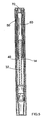
- the device comprises a housing 2 within which are located a cartridge 4 containing a medicinal product, means for setting or selecting the dose of medicinal product to be expelled and means for expelling the selected dose of medicinal product.
- the housing 2 is generally cylindrical in shape and is divided into two compartments by a web 6 to be described in more detail below.
- the cartridge 4 is located within a first part of the housing 2.
- the dose setting means and the means for expelling the selected dose of medicinal product are retained, that is held, within a second part of the housing 2.
- An advantage of a one piece housing enclosing the cartridge 4 together with the dose setting and dose expelling means lies in the ease of assembly of the product. This is in part due to the reduced number of components in the pen-type injector. Also, the unitary nature of the housing 2 means that the pen-type injector is more robust.
- the cartridge 4 may be secured in position in the first part of the housing 2 by any suitable means.
- a needle unit may be secured to a first end of the cartridge 4.
- a temporary covering 8 is shown in this position in the Figures.
- the cartridge 4 further comprises a displaceable piston 10. Advancing the piston 10 towards the first end of the cartridge 4 causes the medicinal product to be expelled from the cartridge 4 through the needle unit.
- a cap 12 is provided to cover the needle unit when the injector is not in use. The cap 12 may be releasably secured to the housing 2 by any suitable means.
- the web 6 dividing the housing 2 is a part of an insert 14 located within the housing 2.
- the insert 14 comprises a first cylindrical portion 16 extending from a first side of the web 6 and second and third cylindrical portions 18, 20 extending from a second side of the web 6.
- the web 6 is provided with a circular opening 22 extending through the web 6.
- the first cylindrical portion 16 extends from a periphery of the web 6.
- the insert 14 is secured to the housing 2 by way of the first cylindrical portion 16 by any suitable means.
- features 24 are provided within the housing 2 and on an outer surface of the first cylindrical portion 16 to enable the insert to be a snap fit to the housing 2.
- the second cylindrical portion 18 extends a small distance from the second side of the web 6 about a periphery of the opening 22.
- An internal surface of the second cylindrical portion is provided with a thread 26.
- the third cylindrical portion 20 extends substantially within the housing 2 from the second side of the web 6.
- the diameter of the third cylindrical portion 20 is such that a first channel 28 is formed between an outer surface of the second cylindrical portion 20 and an inner surface of the third cylindrical portion.
- a second channel 30 is formed between an outer surface of the third cylindrical portion 20 and the housing 2.
- a piston rod 32 extends through the opening in the web 6.
- the piston rod 32 is generally elongate and is provided with a thread 34 extending from a first end of the piston rod 32.
- the thread 34 of the piston rod 32 engages the thread of the inner surface of the second cylindrical portion 18 of the insert 14.
- the first end of the piston rod 32 is provided with a pressure foot 36. In use the pressure foot 36 is disposed on the first side of the web 6 to abut the cartridge piston 10.
- Ratchet means 40 are located adjacent the web 6 on the first side of the web 6.
- the ratchet means 40 serve the purpose of allowing the piston rod 32 only to rotate through the insert 14 in a single direction. Due to the one piece construction of the housing, the ratchet means can be made larger than in known devices and so is stronger (more rigid).
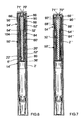
- a dose dial sleeve 50 of generally cylindrical form comprises a first section of first diameter and a second section of second diameter. The first section is located within the second channel 30.
- An inner surface of the first section and the outer surface of the third cylindrical portion 20 are provided with interengaging features to provide a helical thread 52 between the insert 14 and the dose dial sleeve 50. In the illustrated embodiment this was achieved by a helical track provided on the outer surface of the third cylindrical portion 20 within which a helical rib provided on the inner surface of the dose dial sleeve 50 may run. This enables the dose dial sleeve 50 to rotate about and along the third cylindrical portion 20 of the insert 14.
- An outer surface of the first section of the dose dial sleeve 50 is provided with graphics 53.
- the graphics are typically a sequence of reference numerals.
- the housing 2 is provided with an aperture or window 54 through which a portion of the graphics, representing a dosage value selected by the user, may be viewed.
- the graphics 53 may be applied to the dose dial sleeve 50 by any suitable means.
- the graphics 53 are provided in the form of a printed label encircling the dose dial sleeve 50.
- the graphics may take the form of a marked sleeve clipped to the dose dial sleeve 50.
- the graphics may be marked in any suitable manner, for example by laser marking.
- the helical thread 52 is formed within the dose dial sleeve between the dose dial sleeve and the insert. As can be seen this means there is no direct route from outside the injector to the working surfaces of the helical thread. Should dust or dirt enter the pen this will tend to occur between the housing and the dose dial sleeve where there are no working parts with which to interfere. This is not the case for known devices in which a helical thread is formed between the housing and an interior moving surface.
- the helical thread 52 is more efficient and easier to overhaul. This arrangement also produces an improvement in the dose size that can be delivered for a particular linear travel of the dose expelling means.
- the second section of the dose dial sleeve 50 is preferably of the same outer diameter as the housing 2. Within the dose dial sleeve 50 there is a shoulder 56 between the first section of the dose dial sleeve 50 and the second section of the dose dial sleeve 50.
- a drive sleeve 60 of generally cylindrical form comprises a first part of first diameter and a second part of second diameter. A first end of the first part is located within the first channel 28 of the insert 14 in the position shown in Figure 1 .
- the first part of the drive sleeve 60 may be considered as comprising a first portion aligned with a second portion. More generally in the position shown in Figure 1 the first portion of the drive sleeve 60 is located between the insert 14 and the piston rod 32 while the second portion is located between the piston rod 32 and the dose dial sleeve 50.
- a second end of the piston rod 32 and an internal surface of the drive sleeve 60 are splined together such that no relative rotation may occur between these parts, only longitudinal displacement.
- the outer surface of the second portion of the first part of the drive sleeve 60 is provided with a helical thread 62.
- a nut 64 is provided on the helical thread 62 between the drive sleeve 60 and the dose dial sleeve 50.
- the dose dial sleeve 50 and the nut 64 are splined together by spline means to prevent relative rotation between the nut 64 and the dose dial sleeve 50.
- the second part of the drive sleeve 60 is of larger diameter than the first part of the drive sleeve 60. There is a step 66 between the first part of the drive sleeve 60 and the second part. The second part of the drive sleeve 60 is seated within the second section of the dose dial sleeve 50. The shoulder 56 of the dose dial sleeve 50 and the step 66 of the drive sleeve 60 are adapted to be releasably engagable with one another to form a clutch means.
- the clutch means comprises a plurality of radially extending longitudinally directed teeth provided respectively on the shoulder 56 of the dose dial sleeve 50 and the step 66 of the drive sleeve 60.
- the respective teeth will ride over one another.
- the radial separation of the respective teeth corresponds to a unit dosage.
- the second part of the drive sleeve 60 further comprises a central receiving area 68 having a peripheral recess.
- a button 70 of generally "T" shaped configuration is provided, the stem of which is retained within the receiving area.
- the stem of the button 70 is provided with a peripheral bead 71 that is retained in the peripheral recess, the button 70 being able freely to rotate with respect to the drive sleeve 60, but being retained axially therewith.
- Clicker means are provided between the second section of the dose dial sleeve 50 and the second part of the drive sleeve 60.
- the internal surface of the second section of the dose dial sleeve 50 is provided with a plurality of longitudinally extending teeth. The radial separation of the teeth preferably corresponds to a unit dosage.
- the second part of the drive sleeve 60 carries a flexible toothed member 72. Relative rotation between the dose dial sleeve 50 and the drive sleeve 60 will cause the flexible toothed member 72 to ride over the teeth to produce a series of clicks.
- the injector is provided with a filled cartridge 4.
- a user To operate the injector a user must first select a dose.
- the dose dial sleeve 50 is rotated by manipulating the second section of the dose dial sleeve 50 with respect to the housing 2 until the desired dose value is visible through the window 54. This action draws the dose dial sleeve 50 along the second cylindrical portion of the insert 14.
- the drive sleeve 60 cannot rotate since it is splined to the piston rod 32.
- the piston rod 32 does not rotate due to the action of the ratchet means 40.
- the drive sleeve 60 is carried away from the web 6 along the piston rod 32 by the dose dial sleeve 50 as the dose dial sleeve 50 moves out from the housing 2.
- the relative rotation between the dose dial sleeve 50 and the drive sleeve 60 causes the flexible toothed member 72 to ride over the ridges in the drive sleeve 60 to create a series of clicks. This is an audible confirmation of the dose being dialled.
- the relative rotation between the dose dial sleeve 50 and the drive sleeve 60 causes the nut 64 to precess along the helical thread 62 of the drive sleeve 60.
- the user depresses the button 70 to urge the button 70 towards the first end of the housing 2.
- the button 70 is depressed the second part of the drive sleeve 60 is driven into the second section of the dose dial sleeve 50 to engage the clutch means therebetween to prevent relative rotation between the dose dial sleeve 50 and the drive sleeve 60.
- the drive sleeve 60 may still rotate with respect to the button 70. Further longitudinal movement of the button 70 causes the dose dial sleeve 50 (together with the drive sleeve 60) to rotate towards the first end of the injector.
- piston rod 32 Since the piston rod 32 is splined to the drive sleeve 60, the piston rod 32 is also rotated through the insert 14 and the ratchet means 40 towards the first end of the injector, thereby to advance the cartridge piston 10 and expel the desired dose of medicinal product. The piston rod 32 continues to advance until the drive sleeve 60 and dose dial sleeve 50 have returned to their initial positions ( Figure 3 ).
- the dose selecting means and the dose expelling means extend beyond a second end of the housing 2 as the dose is selected and are returned within the housing 2 as the selected dose is expelled.
- FIG. 4 shows an example of a subsequently selected dosage.
- the nut 64 has advanced further along the helical thread 62 of the drive sleeve 60.
- the position of the nut 64 along the helical thread 62 corresponds to the amount of medicinal product remaining in the cartridge 4, such that when the nut 64 reaches the end of the helical thread 62 (in the illustrated embodiment adjacent to the step 66 of the drive sleeve 60) and can rotate no further this corresponds to no medicinal product remaining in the cartridge 4.
- Figure 5 shows an injector according to the present invention in which the entire medical product within the cartridge 4 has been expelled.
- a second embodiment of the present invention is disclosed in Figure 6 .
- Like reference numerals are used to refer to like parts as between the first and second embodiments.
- the piston rod 32' shown in Figure 6 has a dual start thread.
- the piston foot 36' is reversible. This has advantages in manufacture.
- the structure of the insert 14' has been revised.
- the first side of the web 6' is substantially unchanged.
- the other side of the web is now provided with a boss 80.
- a cylindrical portion 20' extends away from the web 6' about a periphery of the boss 80.
- Threaded opening 22' extends through the web 6' and the boss 80.
- An end of the cylindrical portion 20' of the insert 14' remote from the web 6' is provided with a stop in the form of a land 104.
- the dose dial sleeve 50' is of modified construction.
- the dose dial sleeve comprises a first cylindrical portion 84 rigidly connected to a second generally cylindrical portion 86.
- An inner surface of the first cylindrical portion 84 and the outer surface of the cylindrical portion 20' of the insert 14' are provided with interengaging features to provide a helical thread 52' between the insert 14' and the dose dial sleeve 50'.
- An outer surface of the first cylindrical portion 84 is provided with the dose graphics.
- the housing 2' is provided with an aperture or window 54' through which a portion of the graphics may be viewed.
- the second generally cylindrical portion 86 comprises a first cylindrical section 88 and a second cylindrical section 90.
- the first section 88 is rigidly keyed to an inner surface of the first portion 84 of the dose dial sleeve 50'.
- the second section 90 is preferably of the same outer diameter as the housing 2'.
- a nut 64' is provided on the helical thread 62' between the drive sleeve 60' and the first cylindrical section 88 of the dose dial sleeve 50'.
- the first cylindrical section 88 and the nut 64' are splined together by spline means to prevent relative rotation between the nut 64' and the dose dial sleeve 50'.
- the shoulder 56' of the dose dial sleeve 50' and a step 66' of a drive sleeve 60' are adapted to be releasably engagable with one another to form a clutch means.
- the clutch means comprises a plurality of radially extending longitudinally directed teeth provided respectively on the shoulder 56' of the dose dial sleeve 50' and the step 66' of the drive sleeve 60'.
- the structure of the drive sleeve 60' has also been modified.
- the second end of the piston rod 32' is provided with a scooped surface within which a domed part 90 of the drive sleeve 60' may extend.
- the domed part 90 is centrally located within a second part of the drive sleeve 60' at a first end of the receiving area.
- the button 70' is of generally "T" shaped configuration.
- the stem of the button 70' is retained within the receiving area.
- the stem of the button 70' is provided with a peripheral bead 71' that is retained in the peripheral recess, the button 70' being able freely to rotate with respect to the drive sleeve 60', but being retained axially therewith.
- a further embodiment of the button 70" and the dose dial sleeve 50" can be seen in Figure 7 . Again like reference numerals are used to refer to like parts.
- the second end of the piston rod 32" is generally U-shaped.
- the limbs of the U-shape are received within a second part of the drive sleeve 60".
- a central receiving area of the drive sleeve 60" is defined by limbs (not shown) located in use between the limbs formed on the second end of the piston rod 32".
- the button 70" is of generally "T” shaped configuration.
- the stem of the button 70" is retained within the receiving area.
- the stem of the button 70" is provided with a peripheral bead 71" that is retained in the peripheral recess, the button 70" being able freely to rotate with respect to the drive sleeve 60", but being retained axially therewith.
- the second generally cylindrically portion 86" of the dose dial sleeve 50" comprises a first cylindrical section 88" and a second cylindrical section 90" connected by a radial flange 92 extending from a part of the second section, the first section 88" being rigidly keyed to an inner surface of the first portion 84" of the dose dial sleeve 50", and the second section 90" being of the same outer diameter as the housing 2".
- a radially directed lug 100 extending generally parallel to a longitudinal axis of the sleeve.
- a catch means At a second end of the insert on an external surface thereof there is provided a catch means.
- the catch means comprises a groove 102 extending about a central land 104.
- the central land 104 is generally wedge shaped such that a first edge 106 nearer the start of the thread extends radially less far than a second opposite edge 108 located further along the thread.
- a sloping surface 110 is defined between the first edge 106 and the second edge 108.
- the lug 100 passes over the first edge 106 and over the sloping surface 110. As the lug 100 passes fully over the land 104 some elastic deformation of the respective elements, the dose dial sleeve and the insert occurs. Once the lug 100 is over the land 104, the second edge 108 of the land 104 acts as a stop to prevent removal of the dose dial sleeve from the insert.
- the location of the second edge 108 of the land 104 is conveniently chosen at a radial location corresponding to 80 units of medicinal product, that is the maximum dose available is 80 units when the dose dial sleeve is wound from the initial position shown in any of Figures 1 , 6 or 7 to a fully extended position with the second edge 108 of the land 104 contacting the lug 100.
- FIG. 10 A fourth embodiment of the present invention is disclosed in Figure 10 .
- Like reference numerals are used to refer to like parts.
- the structure of the insert 14"' has been revised.
- the first side of the web 6"' is substantially unchanged.
- the other side of the web is now provided with a boss 80"'.
- a radial flange 112 extends outwardly from the boss 80"', the radial flange 112 being spaced from the web 6"', and a cylindrical portion 20"' extending away from the web 6"' about a periphery of the radial flange 110.
- a threaded opening 22"' extends through the web 6"' and the boss 80"'.
- the dose dial sleeve 50"' is of modified construction.
- the dose dial sleeve 50"' comprises a first cylindrical portion 84"' rigidly connected to a second generally cylindrical portion 86"'.
- An inner surface of the first portion 84"' and the outer surface of the cylindrical portion 20"' of the insert 14"' are provided with interengaging features to provide a helical thread 52"' between the insert 14"' and the dose dial sleeve 50"'.
- An outer surface of the first cylindrical portion 84"' is provided with the dose graphics.
- the housing 2"' is provided with an aperture or window 54"' through which a portion of the graphics may be viewed.
- the second generally cylindrical portion 86"' comprises a first inner cylindrical section 88"' and a second outer cylindrical section 90"'.
- the first section 88"' is rigidly keyed to an inner surface of the first portion 84"' of the dose dial sleeve 50"'.
- the second section 90"' is preferably of the same outer diameter as the housing 2"'.
- a nut 64"' is provided on a helical thread 62"' formed on the drive sleeve 60"'.
- the nut 64"' is disposed between the drive sleeve 60"' and the second cylindrical section 88"' of the dose dial sleeve 50"'.
- the second cylindrical section 88"' and the nut 64"' are keyed together by spline means to prevent relative rotation between the nut 64"' and the dose dial sleeve 50"'.
- An upper surface of the radial flange 94 of the dose dial sleeve 50"' and a step 66"' of the drive sleeve 60"' are adapted to be releasably engagable with one another to form a clutch means.
- the dose dial sleeve 50"' and the drive sleeve 60"' are not in engagement the dose dial sleeve 50"' is able to rotate with respect to the drive sleeve 60"'.
- the clutch means comprises a plurality of radially extending longitudinally directed teeth provided respectively on the radial flange 94 of the dose dial sleeve 50"' and the step 66"' of the drive sleeve 60"'.
- the respective teeth will ride over one another.
- a drive mechanism comprising a second main housing 4' having a first end and a second end.
- a cartridge, containing medicinal product can be mounted to the first end of the second main housing 4' and retained by any suitable means.
- the cartridge and its retaining means are not shown in the illustrated embodiment.
- the cartridge may contain a number of doses of a medicinal product and also typically contains a displaceable piston. Displacement of the piston causes the medicinal product to be expelled from the cartridge via a needle (also not shown).
- an insert 16' is provided within the main housing 4'.
- the insert 16' is secured against rotational and axial motion with respect to the second main housing 4'.
- the insert 16' is provided with a threaded circular opening extending therethrough.
- the insert may be formed integrally with the second main housing 4'.
- An internal housing 154 is also provided within the second main housing 4'.
- the internal housing 154 is secured against rotational and axial motion with respect to the second main housing 4'.
- the internal housing 154 is provided with a circular opening extending through its length in which a series of longitudinally directed splines are formed.
- a helical thread 150 extends along the outer cylindrical surface of the internal housing 154.
- the internal housing may be formed integrally with the second main housing 4' and / or with the insert 16'.
- a first thread 19' extends from a first end of a piston rod 20".
- the piston rod 20" is of generally circular section. The first end of the piston rod 20" extends through the threaded opening in the insert 16' and the first thread 19' of the piston rod 20" is engaged with the thread of the insert 16'.
- a pressure foot 22" is located at the first end of the piston rod 20". The pressure foot 22" is disposed to abut a cartridge piston (not shown).
- a second thread 24' extends from a second end of the piston rod 20". The first thread 19' and the second thread 24' are oppositely disposed.
- a drive sleeve 30' extends about the piston rod 20".
- the drive sleeve 30' is generally cylindrical.
- the drive sleeve 30' is provided at a first end with a first radially extending flange 32".
- a second radially extending flange 34' is provided, spaced a distance along the drive sleeve 30' from the first flange 32".
- An external helical thread (not shown) is provided on the outer part of the drive sleeve 30' extending between the first flange 32" and the second flange 34'.
- An internal helical thread extends along the internal surface of the drive sleeve 30'.
- the second thread 24' of the piston rod 20" is engaged with the internal helical thread of the drive sleeve 30'.
- a nut 40' is located between the drive sleeve 30' and the internal housing 154, disposed between the first flange 32" and the second flange 34' of the drive sleeve 30'.
- the nut 40' can be either a 'half-nut' or a 'full-nut'.
- the nut 40' has an internal thread that is engaged with the external helical thread of the drive sleeve 30'.
- the outer surface of the nut 40' and an internal surface of the internal housing 154 are keyed together by means of longitudinally directed splines to prevent relative rotation between the nut 40' and the internal housing 154, while allowing relative longitudinal movement therebetween.
- a clicker 50"" and a clutch 60"" are disposed about the drive sleeve 30', between the drive sleeve 30' and the internal housing 154.
- the clicker 50"" is located adjacent the second flange 34' of the drive sleeve 30'.
- the clicker 50"" includes at least one spring member (not shown).
- the clicker 50"" also includes a set of teeth (not shown) having a triangular profile disposed towards the second end of the drive mechanism.
- the at least one spring member of the clicker 50"" applies an axial force between the flange 34' of the drive sleeve 30' and the clutch 60"".
- the outer surface of the clicker 50"" and an internal surface of the internal housing 154 are keyed together by means of longitudinally directed splines to prevent relative rotation between the clicker 50"" and the internal housing 154, while allowing relative longitudinal movement therebetween.
- the clutch 60"" is located adjacent the second end of the drive sleeve 30'.
- the clutch 60"" is generally cylindrical and is provided at its' first end with a plurality of teeth of triangular profile disposed about the circumference (not shown), that act upon the teeth of the clicker 50"".
- the shoulder 158 of the clutch 60”” is disposed between the internal housing 154 and a radially inwardly directed flange of the dose dial grip 76' (described below).
- the shoulder 158 of the clutch 60"” is provided with a plurality of dog teeth (not shown) extending in the direction of the second end of the drive mechanism.
- the clutch 60"" is keyed to the drive sleeve 30' by way of splines (not shown) to prevent relative rotation between the clutch 60"" and the drive sleeve 30'.
- a dose dial sleeve 70"' is provided outside of the internal housing 154 and radially inward from the second main housing 4'.
- a helical thread is provided on an inner surface of the dose dial sleeve 70"'. The helical thread of the dose dial sleeve 70"' is engaged with the helical thread 150 of the internal housing 154.
- the second main housing 4' is provided with a window (not shown) through which part of the outer surface of the dose dial sleeve 70"' may be viewed.
- a visual indication of the dose that may be dialed for example reference numerals (not shown), is provided on the outer surface of the dose dial sleeve 70"'.
- the window of the second main housing 4' allows only the dose that is currently dialed to be viewed.
- a dose dial grip 76' is located towards the second end of the drive mechanism.
- the dose dial grip 76' is secured against rotational and axial motion within respect to the dose dial sleeve 70"'.
- the dose dial grip 76' is provided with a radially inwardly directed flange 160.
- the radially inwardly directed flange 160 of the dose dial grip 76' is provided with a plurality of dog teeth (not shown) extending in the direction of the first end of the drive mechanism to abut the dog teeth of the clutch 60"". Coupling and decoupling of the dog teeth of the dose dial grip 76' with the dog teeth of the clutch 60"" provides a releasable clutch between the dose dial grip 76' and the clutch 60"".
- a button 82' of generally 'T' shaped cross-section is provided at a second end of the drive mechanism.
- a cylindrical feature of the button 82' extends towards the first end of the drive mechanism, through an opening in the dose dial grip 76' and into a recess in the drive sleeve 30'.
- the cylindrical feature of the button 82' is retained for limited axial movement in the drive sleeve 30' and against rotation with respect thereto.
- the cylindrical feature of the button 82' has lugs extending radially (not shown) that abut the second surface of the shoulder 158 of the clutch 60"".
- the second end of the button 82' is generally circular and has a cylindrical skirt about its' periphery that descends towards the first end of the drive mechanism. The skirt of the button 82' is located radially inward from the dose dial grip 76'.
- a user rotates the dose dial grip 76'.
- the spring member of the clicker 50"" applies an axial force to the clutch 60"" in the direction of the second end of the drive mechanism.
- the force exerted by the spring member of the clicker 50"” couples the dog teeth of the clutch 60"" to the dog teeth of the dose dial grip 76' for rotation.
- the associated dose dial sleeve 70"', the drive sleeve 30' and the clutch 60"" all rotate in unison.
- Audible and tactile feedback of the dose being dialed is provided by the clicker 50"" and the clutch 60"".
- torque is transmitted from the teeth at the first end of the clutch 60"" and the teeth of the clicker 50"".
- the clicker 50"" cannot rotate with respect to the internal housing 154, so the at least one spring member of the clicker 50”” deforms allowing the teeth of the clutch 60"" to jump over the teeth of the clicker 50”” producing an audible and tactile 'click'.
- the teeth of the clicker 50"" and the teeth of the clutch 60”” are disposed such that each 'click' corresponds to a conventional unit of the medicinal product, or the like.
- the helical thread of the dose dial sleeve 70"' and the internal helical thread of the drive sleeve 30' have the same lead. This allows the dose dial sleeve 70"' to advance along the thread 150 of the internal housing 154 at the same rate as the drive sleeve 30' advances along the second thread 24' of the piston rod 20". Rotation of the piston rod 20" is prevented due to the opposing direction of the first thread 19' and the second thread 24' of the piston rod 20". The first thread 19' of the piston rod 20" is engaged with the thread of the insert 16' and so the piston rod 20" does not move with respect to the second main housing 4' while a dose is dialed.
- the nut 40' keyed to the internal housing 154, is advanced along the external thread of the drive sleeve 30' by the rotation of the drive sleeve 30'.
- the nut 40' reaches a position where it abuts the second flange 34' of the drive sleeve 30'.
- a radial stop formed on the second surface of the nut 40' contacts a radial stop on the first surface of the second flange 34' of the drive sleeve 30', preventing both the nut 40' and the drive sleeve 30' from being rotated further.
- the drive mechanism allows the dosage to be corrected without dispense of medicinal product from the cartridge.
- the dose dial grip 76' is counter-rotated. This causes the system to act in reverse.
- the torque transmitted through the clutch 60"" causes the teeth at the first end of the clutch 60"" to ride over the teeth of the clicker 50"" to create the clicks corresponding to the dialed dose reduction.
- the user may then dispense this dose by depressing the button 82' in the direction of the first end of the drive mechanism.
- the lugs of the button 82' apply pressure to the second surface of the shoulder 158 of the clutch 60"", displacing the clutch 60"" axially with respect to the dose dial grip 76'.
- This causes the dog teeth on the shoulder 158 of the clutch 60"” to disengage from the dog teeth of the dose dial grip 76'.
- the clutch 60"" remains keyed in rotation to the drive sleeve 30'.
- the dose dial grip 76' and associated dose dial sleeve 70"' are now free to rotate (guided by the helical thread 150 of the internal housing 154).
Abstract
a housing (154) having an external thread (150);
a piston rod (20") having a generally circular section;
a dose dial sleeve (70"'), which is threadedly engaged with the external thread (150) of the housing (154) and being rotatable with respect to the housing (154);
a drive sleeve (30'), located between the housing (154) and the piston rod (20"),
a clutch means (60"") located between the drive sleeve (30') and the dose dial sleeve (70"'),
in which
e) when the dose dial sleeve (70"') and the drive sleeve (30') are de-coupled by the said clutch means (60""), rotation of said dose dial sleeve (70"') with respect to the said drive sleeve (30') is allowed; and
f) when the dose dial sleeve (70"') and drive sleeve (30') are coupled by the said clutch means (60""), rotation of the dose dial sleeve (70"') with respect to the said drive sleeve (30') is prevented,
Description
- The present invention relates to drive mechanisms suitable for use in drug delivery devices, in particular pen-type injectors, having dosage setting means, enabling the administration of medicinal products from a multi-dose cartridge. In particular, the present invention relates to such drug delivery devices where a user may set the dose.
- Such drug delivery devices have application where regular injection by persons without formal medical training occurs, i.e., patients. This is increasingly common amongst those having diabetes where self-treatment enables such persons to conduct effective management of their diabetes.
- These circumstances set a number of requirements for drug delivery devices of this kind. The device must be robust in construction, yet easy to use in terms of the manipulation of the parts, understanding by a user of its operation and the delivery of the required dose of medicament. Dose setting must be easy and unambiguous. In the case of those with diabetes, many users will be physically infirm and may also have impaired vision requiring the drive mechanism to have low dispensing force and an easy to read dose setting display. Where the device is to be disposable rather than reusable, the device should be cheap to manufacture and easy to dispose of (preferably being suitable for recycling). To meet these requirements the number of parts required to assemble the device and the number of material types the device is made from need to be kept to a minimum.
- User operated drug delivery devices are well known within the medical field.
WO9938554A2 -
EP0937471A2 discloses a medication delivery pen having a drive mechanism comprising a unidirectional coupling (i.e., a ratchet) located between the rod barrel tube and the housing. The disclosed drive mechanism is of the direct type, which means that relatively high actuation force is required by the user. - Surprisingly it was found that a drive mechanism comprising a unidirectional coupling and a clutch mechanism according to instant invention provides lower actuation forces for the user or, alternatively, allows application of greater volumes of medicinal products. Additionally, the drive mechanism of instant invention provides the advantage of intuitive, safe, and easy to use correction of a set dose and it further provides improved protection of the working parts from dust and debris.
- Therefore, a first object of instant invention is a drive mechanism for use in a drug delivery device for dispensing a medicinal product comprising:
- a housing having an internal and an external thread;
- a piston rod having a generally circular section, and which is threadedly engaged with the internal thread of the housing;
- a dose dial sleeve, which is threadedly engaged with the external thread of the housing and being rotatable with respect to the housing;
- a drive sleeve, located between the housing and the piston rod,
- a clutch means located between the drive sleeve and the dose dial sleeve,
- which
- a) when the dose dial sleeve and the drive sleeve are de-coupled by the said clutch means, rotation of said dose dial sleeve with respect to the said drive sleeve is allowed; and
- b) when the dose dial sleeve and drive sleeve are coupled by the said clutch means, rotation of the dose dial sleeve with respect to the said drive sleeve is prevented,
- The term "drug delivery device" according to instant invention shall mean a single-dose or multi-dose, disposable or re-useable device designed to dispense a selected dose of a medicinal product, preferably multiple selected doses, e.g. insulin, growth hormones, low molecular weight heparins, and their analogues and/or derivatives etc. Said device may be of any shape, e.g. compact or pen-type. Dose delivery may be provided through a mechanical (optionally manual) or electrical drive mechanism or stored energy drive mechanism, such as a spring, etc. Dose selection may be provided through a manual mechanism or electronic mechanism. Additionally, said device may contain components designed to monitor physiological properties such as blood glucose levels, etc.. Furthermore, the said device may comprise a needle or may be needle-free. In particular, preferred embodiment the term drug delivery device shall mean a disposable multi-dose pen-type device having mechanical and manual dose delivery and dose selection mechanisms, which is designed for regular use by persons without formal medical training such as patients. Preferably, the drug delivery device is of the injector-type. Optionally, the drug delivery device according to instant invention further comprises a nut threadedly connected to the drive sleeve and rotatable with respect to the drive sleeve and which is engaged with the dose dial sleeve to allow axial displacement of the nut with respect to the dose sleeve, but not rotation of the nut with respect to the dose dial sleeve. The term "housing" according to instant invention shall preferably mean an exterior housing ("main housing", "body", "shell") or interior housing ("inner body", "insert") having an internal and an external thread. The housing may be designed to enable the safe, correct, and comfortable handling of the drug delivery device or any of its mechanisms. Usually, it is designed to house, fix, protect, guide, and/or engage with any of the inner components of the drug delivery device (e.g., the drive mechanism, cartridge, plunger, piston rod) by limiting the exposure to contaminants, such as liquid, dust, dirt etc. In general, the housing may be unitary or a multipart component of tubular or non-tubular shape. Usually, the exterior housing serves to house a cartridge from which a number of doses of a medicinal product may by dispensed.
- In a more specific embodiment of instant invention, the interior housing is provided with a plurality of maximum dose stops adapted to be abutted by a radial stop provided on the dose dial sleeve.
- In a more particular embodiment of instant invention, the interior housing comprises a web having an opening through which the piston may extend. A first cylindrical portion may extend from the first end of the web, and a second and a third cylindrical portion may extend from the second end of the web. Preferably, the second cylindrical portion is provided with an internal thread.
- In a further embodiment of instant invention, the insert comprises a web having an opening through which the piston may extend. A first cylindrical portion may extend from a first end of the web, a boss provided on a second end of the web and a cylindrical portion extending away from the web about a periphery of the boss. Optionally, the boss is provided with an internal thread or a radial flange being spaced from the web with a cylindrical portion extending away from the web about a periphery of the radial flange.
- The term "engaged" according to instant invention shall particularly mean the interlocking of two or more components of the drive mechanism/drug delivery device, e.g. a spline or thread connection, preferably the interlocking of helical threads of components ("threadedly engaged").
- The term "thread" according to instant invention shall preferably mean a full or part thread, e.g., a cylindrical spiral rib/groove, usually of helical nature, located on the internal and/or external surface of a component of the drug delivery device ("internal thread" and/or "external thread"), having an essentially triangular or square or rounded section designed to allow continuous free rotational and/or axial movement between components. Optionally, a thread may be further designed to prevent rotational or axial movement of certain components in one direction.
- The term "dose dial sleeve" according to instant invention shall mean an essentially tubular component of essentially circular cross-section having either:
- a) both an internal and external thread, or
- b) an internal thread, or
- c) an external thread,
- Preferably, the "dose dial sleeve" according to instant invention comprises an internal helical thread, which is threadedly engaged with the external thread of the housing, particularly the insert.
- In yet another preferred embodiment the dose dial sleeve is designed to indicate a selected dose of a dispensable product. In still another preferred embodiment of instant invention, the maximum selectable dose may be determined by the abutment of a radially directed lug on the dose dial sleeve with a catch means on the insert following the maximum angular displacement of the dose dial sleeve with respect to the housing. Preferably, the radially directed lug extends parallel to a longitudinal axis of the dose dial sleeve. Generally, the term "catch means" according to instant invention shall mean any constructive feature, which serves as a counterpart to the lug on the dose dial sleeve and which is preferably located on the outer surface of the insert, and which together with the lug of the dose dial sleeve defines the maximum allowable dosage of the mechanism. Optionally, the catch means may be a groove extending about a central land, e.g., a central land being wedge shaped such that a first edge extends radially less far than a second opposite edge to define a sloping surface between the first edge and the second edge.
- Indication of the selected dose on the dose dial sleeve may be achieved by use of markings, symbols, numerals, etc., e.g. printed on the external surface of the dose dial sleeve or an odometer, or the like.
- In a more specific embodiment of instant invention, the dose dial sleeve comprises a first section of a first diameter and a second section of a second diameter.
- The term "lead" according to instant invention shall preferably mean the axial distance a nut would advance in one complete revolution; preferably "lead" shall mean the axial distance through which a component having a helical thread, i.e. dose dial sleeve, drive sleeve, piston rod, etc., of the drive mechanism travels during one rotation. Therefore lead is a function of the pitch of the thread of the relevant component.
- The term "pitch" according to instant invention shall preferably mean the distance between consecutive contours on a helical thread, measured parallel to the axis of the helical thread.
- The term "drive sleeve" according to instant invention shall mean any essentially tubular component of essentially circular cross-section and which is further located between the housing, preferably the internal housing and the piston rod, and which is axially displaceable but not rotatable with respect to the piston rod. The drive sleeve of the invention is further releasibly connected to the dose dial sleeve by a clutch means and is further engaged with the piston rod at the distal and/or proximal end.
- The drive sleeve may further comprise a first section of first diameter located between the insert and the piston rod and a second section of second diameter located between the piston rod and the dose dial sleeve.
- The term "releasibly connected" according to instant invention shall preferably mean that two components of instant mechanism or device are reversibly joined to each other, which allows coupling and decoupling, e.g., by means of a clutch.
- The term "piston rod" according to instant invention shall mean a component adapted to operate through/within the housing, designed to translate axial movement through/within the drug delivery device, preferably from the drive sleeve to the piston, for the purpose of discharging/dispensing an injectable product. Said piston rod may be flexible or not. It may be a simple rod, a lead-screw, or the like. The "piston rod" according to instant invention shall further mean a component having a non-circular cross-section and an external thread located on its first end. It may be made of any suitable material known by a person skilled in the art.
- The term "first end" according to instant invention shall mean the proximal end. The proximal end of the device or a component of the device shall mean the end, which is closest to the dispensing end of the device.
- The term "second end" according to instant invention shall mean the distal end.
- The distal end of the device or a component of the device shall mean the end, which is furthest away from the dispensing end of the device.
- The term "clutch means" according to instant invention shall mean any means, which releasibly connects the dose dial sleeve and the drive sleeve and which is located between the drive sleeve and the dose dial sleeve, and which allows rotation of the dose dial sleeve with respect to said drive sleeve when the dose dial sleeve and the drive sleeve are de-coupled, and which prevents rotation of the dose dial sleeve with respect to the drive sleeve when the dose dial sleeve and drive sleeve are coupled.
- According to instant invention the term "clutch means" encompasses any clutch mechanism engaging for the purpose of reversibly locking two components in rotation, e.g., by use of axial forces to engage a set of face teeth (saw teeth, dog teeth, crown teeth) or any other suitable frictional faces.
- In still another embodiment of instant invention, the drive mechanism further comprises a clicker means. Preferably, the "clicker means" shall mean any means located between the dose dial sleeve and the drive sleeve, which upon relative rotation of the said drive sleeve and the said dose dial sleeve causes a series of audible and/or tactile clicks.
- Such a clicker means may comprise a plurality of longitudinally extending teeth and a flexible toothed member, one of the plurality of teeth and the toothed member being provided on the dose dial sleeve, the other being provided on the drive sleeve.
- The term "unidirectional coupling" according to instant invention shall mean any mechanism located between the housing and the piston rod, which allows movement of the piston rod in the proximal direction and prevents movement of the piston rod in the distal direction, preferably acting between the non-circular cross section of the piston rod and the housing.
- A second aspect of instant invention provides an assembly for use in a drug delivery device comprising the drive mechanism according to instant invention.
- A third aspect of the present invention provides a drug delivery device comprising the drive mechanism or the assembly according to instant invention.
- A fourth aspect of the present invention provides a method of assembling a drug delivery device comprising the step of providing a drive mechanism or an assembly according to instant invention.
- A fifth aspect of instant invention is the use of a drug delivery device according to instant invention for dispensing a medicinal product, preferably dispensing a pharmaceutical formulation (e.g. solution, suspension etc.) comprising an active compound selected from the group consisting of insulin, growth hormone, low molecular weight heparin, their analogues and their derivatives.
- Without any limitation, the instant invention will be explained in greater detail below in connection with a preferred embodiment and with reference to the drawings in which:
-
Figure 1 shows a sectional view of a first embodiment of the drug delivery device in accordance with the present invention in a first, cartridge full, position; -
Figure 2 shows a sectional view of the drug delivery device ofFigure 1 in a second, maximum first dose dialed, position; -
Figure 3 shows a sectional view of the drug delivery device ofFigure 1 in a third, maximum first dose dispensed, position; -
Figure 4 shows a sectional view of the drug delivery device ofFigure 1 in a fourth, final dose dialed, position; -
Figure 5 shows a sectional view of the drug delivery device ofFigure 1 in a fifth, final dose dispensed, position; -
Figure 6 shows a sectional view of a second embodiment of the drug delivery device in accordance with the present invention; -
Figure 7 shows a sectional side view of a third embodiment of the drug delivery device in accordance with the present invention; -
Figure 8 shows a perspective view of a dose dial sleeve for use in conjunction with the present invention; -
Figure 9 shows a perspective view of an insert for use with the dose dial sleeve ofFigure 8 ; -
Figure 10 shows a sectional side view of a fourth embodiment of the drug delivery device in accordance with the present invention; and -
Figure 11 shows a sectional side view of a fifth embodiment of the drive mechanism according to instant invention in a first, cartridge full, position. - Referring to
Figures 1 to 5 there is seen a drug delivery device in accordance with the first embodiment of the present invention. The device comprises ahousing 2 within which are located acartridge 4 containing a medicinal product, means for setting or selecting the dose of medicinal product to be expelled and means for expelling the selected dose of medicinal product. Thehousing 2 is generally cylindrical in shape and is divided into two compartments by aweb 6 to be described in more detail below. Thecartridge 4 is located within a first part of thehousing 2. The dose setting means and the means for expelling the selected dose of medicinal product are retained, that is held, within a second part of thehousing 2. An advantage of a one piece housing enclosing thecartridge 4 together with the dose setting and dose expelling means lies in the ease of assembly of the product. This is in part due to the reduced number of components in the pen-type injector. Also, the unitary nature of thehousing 2 means that the pen-type injector is more robust. - The
cartridge 4 may be secured in position in the first part of thehousing 2 by any suitable means. A needle unit may be secured to a first end of thecartridge 4. Atemporary covering 8 is shown in this position in the Figures. Thecartridge 4 further comprises adisplaceable piston 10. Advancing thepiston 10 towards the first end of thecartridge 4 causes the medicinal product to be expelled from thecartridge 4 through the needle unit. Acap 12 is provided to cover the needle unit when the injector is not in use. Thecap 12 may be releasably secured to thehousing 2 by any suitable means. - The dose setting means and the means for expelling the selected dose of medicinal product will now be described in more detail. The
web 6 dividing thehousing 2 is a part of aninsert 14 located within thehousing 2. Theinsert 14 comprises a firstcylindrical portion 16 extending from a first side of theweb 6 and second and thirdcylindrical portions web 6. Theweb 6 is provided with acircular opening 22 extending through theweb 6. - The first
cylindrical portion 16 extends from a periphery of theweb 6. Theinsert 14 is secured to thehousing 2 by way of the firstcylindrical portion 16 by any suitable means. In the illustrated embodiment features 24 are provided within thehousing 2 and on an outer surface of the firstcylindrical portion 16 to enable the insert to be a snap fit to thehousing 2. - The second
cylindrical portion 18 extends a small distance from the second side of theweb 6 about a periphery of theopening 22. An internal surface of the second cylindrical portion is provided with athread 26. - The third
cylindrical portion 20 extends substantially within thehousing 2 from the second side of theweb 6. The diameter of the thirdcylindrical portion 20 is such that afirst channel 28 is formed between an outer surface of the secondcylindrical portion 20 and an inner surface of the third cylindrical portion. Asecond channel 30 is formed between an outer surface of the thirdcylindrical portion 20 and thehousing 2. - A
piston rod 32 extends through the opening in theweb 6. Thepiston rod 32 is generally elongate and is provided with athread 34 extending from a first end of thepiston rod 32. Thethread 34 of thepiston rod 32 engages the thread of the inner surface of the secondcylindrical portion 18 of theinsert 14. The first end of thepiston rod 32 is provided with apressure foot 36. In use thepressure foot 36 is disposed on the first side of theweb 6 to abut thecartridge piston 10. - Ratchet means 40 are located adjacent the
web 6 on the first side of theweb 6. The ratchet means 40 serve the purpose of allowing thepiston rod 32 only to rotate through theinsert 14 in a single direction. Due to the one piece construction of the housing, the ratchet means can be made larger than in known devices and so is stronger (more rigid). - A
dose dial sleeve 50 of generally cylindrical form comprises a first section of first diameter and a second section of second diameter. The first section is located within thesecond channel 30. An inner surface of the first section and the outer surface of the thirdcylindrical portion 20 are provided with interengaging features to provide ahelical thread 52 between theinsert 14 and thedose dial sleeve 50. In the illustrated embodiment this was achieved by a helical track provided on the outer surface of the thirdcylindrical portion 20 within which a helical rib provided on the inner surface of thedose dial sleeve 50 may run. This enables thedose dial sleeve 50 to rotate about and along the thirdcylindrical portion 20 of theinsert 14. - An outer surface of the first section of the
dose dial sleeve 50 is provided withgraphics 53. The graphics are typically a sequence of reference numerals. Thehousing 2 is provided with an aperture orwindow 54 through which a portion of the graphics, representing a dosage value selected by the user, may be viewed. - The
graphics 53 may be applied to thedose dial sleeve 50 by any suitable means. In the illustrated embodiment, thegraphics 53 are provided in the form of a printed label encircling thedose dial sleeve 50. Alternatively the graphics may take the form of a marked sleeve clipped to thedose dial sleeve 50. The graphics may be marked in any suitable manner, for example by laser marking. - It is an advantage of this arrangement that the
helical thread 52 is formed within the dose dial sleeve between the dose dial sleeve and the insert. As can be seen this means there is no direct route from outside the injector to the working surfaces of the helical thread. Should dust or dirt enter the pen this will tend to occur between the housing and the dose dial sleeve where there are no working parts with which to interfere. This is not the case for known devices in which a helical thread is formed between the housing and an interior moving surface. In addition because of the narrower diameter of thehelical thread 52 formed between the dose dial sleeve and the drive sleeve in comparison to a similar thread formed between the housing and the dose dial sleeve, thehelical thread 52 is more efficient and easier to overhaul. This arrangement also produces an improvement in the dose size that can be delivered for a particular linear travel of the dose expelling means. The second section of thedose dial sleeve 50 is preferably of the same outer diameter as thehousing 2. Within thedose dial sleeve 50 there is ashoulder 56 between the first section of thedose dial sleeve 50 and the second section of thedose dial sleeve 50. - A
drive sleeve 60 of generally cylindrical form comprises a first part of first diameter and a second part of second diameter. A first end of the first part is located within thefirst channel 28 of theinsert 14 in the position shown inFigure 1 . The first part of thedrive sleeve 60 may be considered as comprising a first portion aligned with a second portion. More generally in the position shown inFigure 1 the first portion of thedrive sleeve 60 is located between theinsert 14 and thepiston rod 32 while the second portion is located between thepiston rod 32 and thedose dial sleeve 50. - A second end of the
piston rod 32 and an internal surface of thedrive sleeve 60 are splined together such that no relative rotation may occur between these parts, only longitudinal displacement. - The outer surface of the second portion of the first part of the
drive sleeve 60 is provided with ahelical thread 62. Anut 64 is provided on thehelical thread 62 between thedrive sleeve 60 and thedose dial sleeve 50. Thedose dial sleeve 50 and thenut 64 are splined together by spline means to prevent relative rotation between thenut 64 and thedose dial sleeve 50. - The second part of the
drive sleeve 60 is of larger diameter than the first part of thedrive sleeve 60. There is astep 66 between the first part of thedrive sleeve 60 and the second part. The second part of thedrive sleeve 60 is seated within the second section of thedose dial sleeve 50. Theshoulder 56 of thedose dial sleeve 50 and thestep 66 of thedrive sleeve 60 are adapted to be releasably engagable with one another to form a clutch means. When, as inFigure 1 , thedose dial sleeve 50 and thedrive sleeve 60 are not in engagement thedose dial sleeve 50 is able to rotate with respect to thedrive sleeve 60. Conveniently, the clutch means comprises a plurality of radially extending longitudinally directed teeth provided respectively on theshoulder 56 of thedose dial sleeve 50 and thestep 66 of thedrive sleeve 60. When thedose dial sleeve 50 and thedrive sleeve 60 are not forced together the respective teeth will ride over one another. Preferably, the radial separation of the respective teeth corresponds to a unit dosage. - The second part of the
drive sleeve 60 further comprises acentral receiving area 68 having a peripheral recess. Abutton 70 of generally "T" shaped configuration is provided, the stem of which is retained within the receiving area. The stem of thebutton 70 is provided with aperipheral bead 71 that is retained in the peripheral recess, thebutton 70 being able freely to rotate with respect to thedrive sleeve 60, but being retained axially therewith. - Clicker means are provided between the second section of the
dose dial sleeve 50 and the second part of thedrive sleeve 60. In the illustrated embodiment, the internal surface of the second section of thedose dial sleeve 50 is provided with a plurality of longitudinally extending teeth. The radial separation of the teeth preferably corresponds to a unit dosage. The second part of thedrive sleeve 60 carries a flexibletoothed member 72. Relative rotation between thedose dial sleeve 50 and thedrive sleeve 60 will cause the flexibletoothed member 72 to ride over the teeth to produce a series of clicks. - In
Figure 1 , the injector is provided with a filledcartridge 4. To operate the injector a user must first select a dose. To set a dose thedose dial sleeve 50 is rotated by manipulating the second section of thedose dial sleeve 50 with respect to thehousing 2 until the desired dose value is visible through thewindow 54. This action draws thedose dial sleeve 50 along the second cylindrical portion of theinsert 14. Thedrive sleeve 60 cannot rotate since it is splined to thepiston rod 32. Thepiston rod 32 does not rotate due to the action of the ratchet means 40. Thedrive sleeve 60 is carried away from theweb 6 along thepiston rod 32 by thedose dial sleeve 50 as thedose dial sleeve 50 moves out from thehousing 2. The relative rotation between thedose dial sleeve 50 and thedrive sleeve 60 causes the flexibletoothed member 72 to ride over the ridges in thedrive sleeve 60 to create a series of clicks. This is an audible confirmation of the dose being dialled. - Since the
nut 64 is splined to thedose dial sleeve 50, the relative rotation between thedose dial sleeve 50 and thedrive sleeve 60 causes thenut 64 to precess along thehelical thread 62 of thedrive sleeve 60. - Once a desired dose has been set (as shown for example in
Figure 2 ), to deliver the dose the user depresses thebutton 70 to urge thebutton 70 towards the first end of thehousing 2. When thebutton 70 is depressed the second part of thedrive sleeve 60 is driven into the second section of thedose dial sleeve 50 to engage the clutch means therebetween to prevent relative rotation between thedose dial sleeve 50 and thedrive sleeve 60. Thedrive sleeve 60 may still rotate with respect to thebutton 70. Further longitudinal movement of thebutton 70 causes the dose dial sleeve 50 (together with the drive sleeve 60) to rotate towards the first end of the injector. Since thepiston rod 32 is splined to thedrive sleeve 60, thepiston rod 32 is also rotated through theinsert 14 and the ratchet means 40 towards the first end of the injector, thereby to advance thecartridge piston 10 and expel the desired dose of medicinal product. Thepiston rod 32 continues to advance until thedrive sleeve 60 anddose dial sleeve 50 have returned to their initial positions (Figure 3 ). - It can be seen that the dose selecting means and the dose expelling means extend beyond a second end of the
housing 2 as the dose is selected and are returned within thehousing 2 as the selected dose is expelled. - Further dosages may be delivered as required.
Figure 4 shows an example of a subsequently selected dosage. It will be noted that thenut 64 has advanced further along thehelical thread 62 of thedrive sleeve 60. The position of thenut 64 along thehelical thread 62 corresponds to the amount of medicinal product remaining in thecartridge 4, such that when thenut 64 reaches the end of the helical thread 62 (in the illustrated embodiment adjacent to thestep 66 of the drive sleeve 60) and can rotate no further this corresponds to no medicinal product remaining in thecartridge 4. It will be seen that if a user seeks to select a quantity of medical product greater than that remaining in thecartridge 4, this cannot be done since when thenut 64 stops rotating thedose dial sleeve 50 and thedrive sleeve 60 will become locked together preventing rotation of thedose dial sleeve 50 and setting of a larger dose.Figure 5 shows an injector according to the present invention in which the entire medical product within thecartridge 4 has been expelled. - A second embodiment of the present invention is disclosed in
Figure 6 . Like reference numerals are used to refer to like parts as between the first and second embodiments. - The piston rod 32' shown in
Figure 6 has a dual start thread. The piston foot 36' is reversible. This has advantages in manufacture. As can be seen the structure of the insert 14' has been revised. The first side of the web 6' is substantially unchanged. The other side of the web is now provided with aboss 80. A cylindrical portion 20' extends away from the web 6' about a periphery of theboss 80. Threaded opening 22' extends through the web 6' and theboss 80. An end of the cylindrical portion 20' of the insert 14' remote from the web 6' is provided with a stop in the form of aland 104. - The dose dial sleeve 50' is of modified construction. The dose dial sleeve comprises a first
cylindrical portion 84 rigidly connected to a second generallycylindrical portion 86. An inner surface of the firstcylindrical portion 84 and the outer surface of the cylindrical portion 20' of the insert 14' are provided with interengaging features to provide a helical thread 52' between the insert 14' and the dose dial sleeve 50'. An outer surface of the firstcylindrical portion 84 is provided with the dose graphics. The housing 2' is provided with an aperture or window 54' through which a portion of the graphics may be viewed. - The second generally
cylindrical portion 86 comprises a firstcylindrical section 88 and a secondcylindrical section 90. Thefirst section 88 is rigidly keyed to an inner surface of thefirst portion 84 of the dose dial sleeve 50'. Thesecond section 90 is preferably of the same outer diameter as the housing 2'. Within the dose dial sleeve 50' there is a shoulder 56' between thefirst section 86 and thesecond section 90. - A
nut 64' is provided on the helical thread 62' between the drive sleeve 60' and the firstcylindrical section 88 of the dose dial sleeve 50'. The firstcylindrical section 88 and thenut 64' are splined together by spline means to prevent relative rotation between thenut 64' and the dose dial sleeve 50'. - The shoulder 56' of the dose dial sleeve 50' and a step 66' of a drive sleeve 60' are adapted to be releasably engagable with one another to form a clutch means. When, as in
Figure 6 , the dose dial sleeve 50' and the drive sleeve 60' are not in engagement the dose dial sleeve 50' is able to rotate with respect to the drive sleeve 60'. Conveniently, the clutch means comprises a plurality of radially extending longitudinally directed teeth provided respectively on the shoulder 56' of the dose dial sleeve 50' and the step 66' of the drive sleeve 60'. When the dose dial sleeve 50' and the drive sleeve 60' are not forced together the respective teeth will ride over one another. - It will be seen that the structure of the drive sleeve 60' has also been modified. The second end of the piston rod 32' is provided with a scooped surface within which a
domed part 90 of the drive sleeve 60' may extend. Thedomed part 90 is centrally located within a second part of the drive sleeve 60' at a first end of the receiving area. - The button 70' is of generally "T" shaped configuration. The stem of the button 70' is retained within the receiving area. The stem of the button 70' is provided with a peripheral bead 71' that is retained in the peripheral recess, the button 70' being able freely to rotate with respect to the drive sleeve 60', but being retained axially therewith.
- When the button 70' is depressed the drive sleeve 60' is urged into contact with the dose dial sleeve 50' such that the clutch means are engaged. At the same time, the scooped surface of the piston rod 32' and the domed surface of the drive sleeve approach but do not contact one another. The advantage of this structure is that it enables the overall length of the device to be reduced thereby enabling easier operation of the device when expressing fluid from a cartridge.
- A further embodiment of the
button 70" and thedose dial sleeve 50" can be seen inFigure 7 . Again like reference numerals are used to refer to like parts. In the embodiment ofFigure 7 , the overall length of the device may be reduced still further. The second end of thepiston rod 32" is generally U-shaped. The limbs of the U-shape are received within a second part of thedrive sleeve 60". A central receiving area of thedrive sleeve 60" is defined by limbs (not shown) located in use between the limbs formed on the second end of thepiston rod 32". Thebutton 70" is of generally "T" shaped configuration. The stem of thebutton 70" is retained within the receiving area. The stem of thebutton 70" is provided with aperipheral bead 71" that is retained in the peripheral recess, thebutton 70" being able freely to rotate with respect to thedrive sleeve 60", but being retained axially therewith. - The second generally cylindrically
portion 86" of thedose dial sleeve 50" comprises a firstcylindrical section 88" and a secondcylindrical section 90" connected by aradial flange 92 extending from a part of the second section, thefirst section 88" being rigidly keyed to an inner surface of thefirst portion 84" of thedose dial sleeve 50", and thesecond section 90" being of the same outer diameter as thehousing 2". - In each of
Figures 6 and 7 , there is a further modification to each of the dose dial sleeve and the insert. This may be seen more clearly with reference toFigures 8 and 9 . - At a first end of the dose dial sleeve there is located on an internal surface a radially directed
lug 100 extending generally parallel to a longitudinal axis of the sleeve. At a second end of the insert on an external surface thereof there is provided a catch means. The catch means comprises agroove 102 extending about acentral land 104. Thecentral land 104 is generally wedge shaped such that afirst edge 106 nearer the start of the thread extends radially less far than a secondopposite edge 108 located further along the thread. Asloping surface 110 is defined between thefirst edge 106 and thesecond edge 108. Thus, when the dose dial sleeve is assembled to the insert, by threading the dose dial sleeve onto the insert, thelug 100 passes over thefirst edge 106 and over thesloping surface 110. As thelug 100 passes fully over theland 104 some elastic deformation of the respective elements, the dose dial sleeve and the insert occurs. Once thelug 100 is over theland 104, thesecond edge 108 of theland 104 acts as a stop to prevent removal of the dose dial sleeve from the insert. - The location of the
second edge 108 of theland 104 is conveniently chosen at a radial location corresponding to 80 units of medicinal product, that is the maximum dose available is 80 units when the dose dial sleeve is wound from the initial position shown in any ofFigures 1 ,6 or 7 to a fully extended position with thesecond edge 108 of theland 104 contacting thelug 100. - A fourth embodiment of the present invention is disclosed in
Figure 10 . Like reference numerals are used to refer to like parts. - As can be seen the structure of the
insert 14"' has been revised. The first side of theweb 6"' is substantially unchanged. The other side of the web is now provided with aboss 80"'. Aradial flange 112 extends outwardly from theboss 80"', theradial flange 112 being spaced from theweb 6"', and acylindrical portion 20"' extending away from theweb 6"' about a periphery of theradial flange 110. A threadedopening 22"' extends through theweb 6"' and theboss 80"'. - The
dose dial sleeve 50"' is of modified construction. Thedose dial sleeve 50"' comprises a firstcylindrical portion 84"' rigidly connected to a second generallycylindrical portion 86"'. An inner surface of thefirst portion 84"' and the outer surface of thecylindrical portion 20"' of theinsert 14"' are provided with interengaging features to provide ahelical thread 52"' between theinsert 14"' and thedose dial sleeve 50"'. An outer surface of the firstcylindrical portion 84"' is provided with the dose graphics. Thehousing 2"' is provided with an aperture orwindow 54"' through which a portion of the graphics may be viewed. - The second generally
cylindrical portion 86"' comprises a first innercylindrical section 88"' and a second outercylindrical section 90"'. Thefirst section 88"' is rigidly keyed to an inner surface of thefirst portion 84"' of thedose dial sleeve 50"'. Thesecond section 90"' is preferably of the same outer diameter as thehousing 2"'. Within thedose dial sleeve 50"' there is aradial flange 94 extending between theouter section 90"' and an intermediate part of theinner section 88"'. - A
nut 64"' is provided on ahelical thread 62"' formed on thedrive sleeve 60"'. Thenut 64"' is disposed between thedrive sleeve 60"' and the secondcylindrical section 88"' of thedose dial sleeve 50"'. The secondcylindrical section 88"' and thenut 64"' are keyed together by spline means to prevent relative rotation between thenut 64"' and thedose dial sleeve 50"'. - An upper surface of the
radial flange 94 of thedose dial sleeve 50"' and astep 66"' of thedrive sleeve 60"' are adapted to be releasably engagable with one another to form a clutch means. When, as inFigure 10 , thedose dial sleeve 50"' and thedrive sleeve 60"' are not in engagement thedose dial sleeve 50"' is able to rotate with respect to thedrive sleeve 60"'. Conveniently, the clutch means comprises a plurality of radially extending longitudinally directed teeth provided respectively on theradial flange 94 of thedose dial sleeve 50"' and thestep 66"' of thedrive sleeve 60"'. When thedose dial sleeve 50"' and thedrive sleeve 60"' are not forced together the respective teeth will ride over one another. - In another embodiment of the invention (
Figure 11 ) there is seen a drive mechanism comprising a second main housing 4' having a first end and a second end. A cartridge, containing medicinal product, can be mounted to the first end of the second main housing 4' and retained by any suitable means. The cartridge and its retaining means are not shown in the illustrated embodiment. The cartridge may contain a number of doses of a medicinal product and also typically contains a displaceable piston. Displacement of the piston causes the medicinal product to be expelled from the cartridge via a needle (also not shown). - In the illustrated embodiment, an insert 16' is provided within the main housing 4'. The insert 16' is secured against rotational and axial motion with respect to the second main housing 4'. The insert 16' is provided with a threaded circular opening extending therethrough. Alternatively, the insert may be formed integrally with the second main housing 4'.
- An
internal housing 154 is also provided within the second main housing 4'. Theinternal housing 154 is secured against rotational and axial motion with respect to the second main housing 4'. Theinternal housing 154 is provided with a circular opening extending through its length in which a series of longitudinally directed splines are formed. Ahelical thread 150 extends along the outer cylindrical surface of theinternal housing 154. Alternatively, the internal housing may be formed integrally with the second main housing 4' and / or with the insert 16'. - A first thread 19' extends from a first end of a
piston rod 20". Thepiston rod 20" is of generally circular section. The first end of thepiston rod 20" extends through the threaded opening in the insert 16' and the first thread 19' of thepiston rod 20" is engaged with the thread of the insert 16'. Apressure foot 22" is located at the first end of thepiston rod 20". Thepressure foot 22" is disposed to abut a cartridge piston (not shown). A second thread 24' extends from a second end of thepiston rod 20". The first thread 19' and the second thread 24' are oppositely disposed. - A drive sleeve 30' extends about the
piston rod 20". The drive sleeve 30' is generally cylindrical. The drive sleeve 30' is provided at a first end with a firstradially extending flange 32". A second radially extending flange 34' is provided, spaced a distance along the drive sleeve 30' from thefirst flange 32". An external helical thread (not shown) is provided on the outer part of the drive sleeve 30' extending between thefirst flange 32" and the second flange 34'. An internal helical thread extends along the internal surface of the drive sleeve 30'. The second thread 24' of thepiston rod 20" is engaged with the internal helical thread of the drive sleeve 30'. - A nut 40' is located between the drive sleeve 30' and the
internal housing 154, disposed between thefirst flange 32" and the second flange 34' of the drive sleeve 30'. The nut 40' can be either a 'half-nut' or a 'full-nut'. The nut 40' has an internal thread that is engaged with the external helical thread of the drive sleeve 30'. The outer surface of the nut 40' and an internal surface of theinternal housing 154 are keyed together by means of longitudinally directed splines to prevent relative rotation between the nut 40' and theinternal housing 154, while allowing relative longitudinal movement therebetween. - A
clicker 50"" and a clutch 60"" are disposed about the drive sleeve 30', between the drive sleeve 30' and theinternal housing 154. - The
clicker 50"" is located adjacent the second flange 34' of the drive sleeve 30'. Theclicker 50"" includes at least one spring member (not shown). Theclicker 50"" also includes a set of teeth (not shown) having a triangular profile disposed towards the second end of the drive mechanism. When compressed, the at least one spring member of theclicker 50"" applies an axial force between the flange 34' of the drive sleeve 30' and the clutch 60"". The outer surface of theclicker 50"" and an internal surface of theinternal housing 154 are keyed together by means of longitudinally directed splines to prevent relative rotation between theclicker 50"" and theinternal housing 154, while allowing relative longitudinal movement therebetween. - The clutch 60"" is located adjacent the second end of the drive sleeve 30'. The clutch 60"" is generally cylindrical and is provided at its' first end with a plurality of teeth of triangular profile disposed about the circumference (not shown), that act upon the teeth of the
clicker 50"". Towards the second end of the clutch 60"" there is located ashoulder 158. Theshoulder 158 of the clutch 60"" is disposed between theinternal housing 154 and a radially inwardly directed flange of the dose dial grip 76' (described below). Theshoulder 158 of the clutch 60"" is provided with a plurality of dog teeth (not shown) extending in the direction of the second end of the drive mechanism. The clutch 60"" is keyed to the drive sleeve 30' by way of splines (not shown) to prevent relative rotation between the clutch 60"" and the drive sleeve 30'. - A
dose dial sleeve 70"' is provided outside of theinternal housing 154 and radially inward from the second main housing 4'. A helical thread is provided on an inner surface of thedose dial sleeve 70"'. The helical thread of thedose dial sleeve 70"' is engaged with thehelical thread 150 of theinternal housing 154. - The second main housing 4' is provided with a window (not shown) through which part of the outer surface of the
dose dial sleeve 70"' may be viewed. Conveniently, a visual indication of the dose that may be dialed, for example reference numerals (not shown), is provided on the outer surface of thedose dial sleeve 70"'. Conveniently, the window of the second main housing 4' allows only the dose that is currently dialed to be viewed. - A dose dial grip 76' is located towards the second end of the drive mechanism. The dose dial grip 76' is secured against rotational and axial motion within respect to the
dose dial sleeve 70"'. The dose dial grip 76' is provided with a radially inwardly directedflange 160. The radially inwardly directedflange 160 of the dose dial grip 76' is provided with a plurality of dog teeth (not shown) extending in the direction of the first end of the drive mechanism to abut the dog teeth of the clutch 60"". Coupling and decoupling of the dog teeth of the dose dial grip 76' with the dog teeth of the clutch 60"" provides a releasable clutch between the dose dial grip 76' and the clutch 60"". - A button 82' of generally 'T' shaped cross-section is provided at a second end of the drive mechanism. A cylindrical feature of the button 82' extends towards the first end of the drive mechanism, through an opening in the dose dial grip 76' and into a recess in the drive sleeve 30'. The cylindrical feature of the button 82' is retained for limited axial movement in the drive sleeve 30' and against rotation with respect thereto. The cylindrical feature of the button 82' has lugs extending radially (not shown) that abut the second surface of the
shoulder 158 of the clutch 60"". The second end of the button 82' is generally circular and has a cylindrical skirt about its' periphery that descends towards the first end of the drive mechanism. The skirt of the button 82' is located radially inward from the dose dial grip 76'. - Operation of the drive mechanism in accordance with the present invention will now be described.
- To dial a dose, a user rotates the dose dial grip 76'. The spring member of the
clicker 50"" applies an axial force to the clutch 60"" in the direction of the second end of the drive mechanism. The force exerted by the spring member of theclicker 50"" couples the dog teeth of the clutch 60"" to the dog teeth of the dose dial grip 76' for rotation. As the dose dial grip 76' is rotated, the associateddose dial sleeve 70"', the drive sleeve 30' and the clutch 60"" all rotate in unison. - Audible and tactile feedback of the dose being dialed is provided by the
clicker 50"" and the clutch 60"". As the clutch 60"" is rotated, torque is transmitted from the teeth at the first end of the clutch 60"" and the teeth of theclicker 50"". Theclicker 50"" cannot rotate with respect to theinternal housing 154, so the at least one spring member of theclicker 50"" deforms allowing the teeth of the clutch 60"" to jump over the teeth of theclicker 50"" producing an audible and tactile 'click'. Preferably, the teeth of theclicker 50"" and the teeth of the clutch 60"" are disposed such that each 'click' corresponds to a conventional unit of the medicinal product, or the like. - The helical thread of the
dose dial sleeve 70"' and the internal helical thread of the drive sleeve 30' have the same lead. This allows thedose dial sleeve 70"' to advance along thethread 150 of theinternal housing 154 at the same rate as the drive sleeve 30' advances along the second thread 24' of thepiston rod 20". Rotation of thepiston rod 20" is prevented due to the opposing direction of the first thread 19' and the second thread 24' of thepiston rod 20". The first thread 19' of thepiston rod 20" is engaged with the thread of the insert 16' and so thepiston rod 20" does not move with respect to the second main housing 4' while a dose is dialed. - The nut 40', keyed to the
internal housing 154, is advanced along the external thread of the drive sleeve 30' by the rotation of the drive sleeve 30'. When a user has dialed a quantity of medicinal product that is equivalent to the deliverable volume of the cartridge, the nut 40' reaches a position where it abuts the second flange 34' of the drive sleeve 30'. A radial stop formed on the second surface of the nut 40' contacts a radial stop on the first surface of the second flange 34' of the drive sleeve 30', preventing both the nut 40' and the drive sleeve 30' from being rotated further. - Should a user inadvertently dial a quantity greater than the desired dosage, the drive mechanism allows the dosage to be corrected without dispense of medicinal product from the cartridge. The dose dial grip 76' is counter-rotated. This causes the system to act in reverse. The torque transmitted through the clutch 60"" causes the teeth at the first end of the clutch 60"" to ride over the teeth of the
clicker 50"" to create the clicks corresponding to the dialed dose reduction. - When the desired dose has been dialed, the user may then dispense this dose by depressing the button 82' in the direction of the first end of the drive mechanism. The lugs of the button 82' apply pressure to the second surface of the
shoulder 158 of the clutch 60"", displacing the clutch 60"" axially with respect to the dose dial grip 76'. This causes the dog teeth on theshoulder 158 of the clutch 60"" to disengage from the dog teeth of the dose dial grip 76'. However, the clutch 60"" remains keyed in rotation to the drive sleeve 30'. The dose dial grip 76' and associateddose dial sleeve 70"' are now free to rotate (guided by thehelical thread 150 of the internal housing 154). - The axial movement of the clutch 60"" deforms the spring member of the
clicker 50"" and couples the teeth at the first end of the clutch 60"" to the teeth of theclicker 50"" preventing relative rotation therebetween. This prevents the drive sleeve 30' from rotating with respect to theinternal housing 154, though it is still free to move axially with respect thereto. - Pressure applied to the button 82' thus causes the dose dial grip 76' and the associated
dose dial sleeve 70"' to rotate into the second main housing 4'. Under this pressure the clutch 60"", theclicker 50"" and the drive sleeve 30' are moved axially in the direction of the first end of the drive mechanism, but they do not rotate. The axial movement of the drive sleeve 30' causes thepiston rod 20" to rotate though the threaded opening in the insert 16', thereby to advance thepressure foot 22". This applies force to the piston, causing the medicinal product to be expelled from the cartridge. The selected dose is delivered when the dose dial grip 76' returns to a position where it abuts the second main housing 4'. - When pressure is removed from the button 82', the deformation of the spring member of the
clicker 50"" is used to urge the clutch 60"" back along the drive sleeve 30' to re-couple the dog teeth on theshoulder 158 of the clutch 60"" with the dog teeth on the dose dial grip 76'. The drive mechanism is thus reset in preparation to dial a subsequent dose.
Claims (10)
- A drive mechanism for use in a drug delivery device for dispensing a medicinal product comprising:a housing (154) having an external thread (150);a piston rod (20") having a generally circular section;a dose dial sleeve (70"'), which is threadedly engaged with the external thread (150) of the housing (154) and being rotatable with respect to the housing (154);a drive sleeve (30'), located between the housing (154) and the piston rod (20"),a clutch means (60"") located between the drive sleeve (30') and the dose dial sleeve (70"'),in whichc) when the dose dial sleeve (70"') and the drive sleeve (30') are de-coupled by the said clutch means (60""), rotation of said dose dial sleeve (70"') with respect to the said drive sleeve (30') is allowed; andd) when the dose dial sleeve (70"') and drive sleeve (30') are coupled by the said clutch means (60""), rotation of the dose dial sleeve (70"') with respect to the said drive sleeve (30') is prevented,characterized in that a nut (40') is located between the drive sleeve (30') and the housing (154), the nut (40') having a thread that is engaged with a thread of the drive sleeve (30') and the nut (40') and the housing (154) being keyed together by means of longitudinally directed splines to prevent rotation between the nut (40') and the housing (154) while allowing relative longitudinal movement therebetween.
- A drive mechanism according to claim 1, characterized in that the nut (40') is advanced along the external thread of the drive sleeve (30') by the rotation of the drive sleeve (30')
- A drive mechanism according to one of claims 1 or 2, characterized in that the dose dial sleeve (70"'), the drive sleeve (30') and the clutch means (60"") rotate in unison when a dose is dialled.
- A drive mechanism according to one of claims 1 to 3, characterized in that a radially extending flange (34') is provided on the drive sleeve (30'), the nut (40') reaching a position where it abuts the flange (34') of the drive sleeve (30') when a user has dialled a quantity of medicinal product that is equivalent to a deliverable volume of a cartridge of the drug delivery device.
- The drive mechanism according to claim 4, characterized in that a radial stop is formed on a second surface of the nut (40') which contacts a radial stop on a first surface of the flange (34') when the user has dialled the quantity of medicinal product that is equivalent to the deliverable volume of the cartridge of the drug delivery device, preventing both the nut (40') and the drive sleeve (30') from being rotated further.
- A drug delivery device comprising a drive mechanism as claimed in one of claims 1 to 5.
- The drug delivery device according to claim 6, which is a pen-type device.
- The drug delivery device according to any of claims 6 or 7, which is an injector-type device.
- The use of a drug delivery device as defined in any of claims 6 to 8 for dispensing a medicinal product.
- The use of a drug delivery device according to claim 9 for dispensing a pharmaceutical formulation comprising an active compound selected from the group consisting of insulin, growth hormone, low molecular weight heparin, their analogues, and their derivatives.
Priority Applications (3)
| Application Number | Priority Date | Filing Date | Title |
|---|---|---|---|
| SI200432269T SI1944050T1 (en) | 2003-03-03 | 2004-03-03 | Improvements in and relating to drive mechanisms suitable for use in drug delivery devices |
| PL08006911T PL1944050T3 (en) | 2003-03-03 | 2004-03-03 | Improvements in and relating to drive mechanisms suitable for use in drug delivery devices |
| CY20151100907T CY1116794T1 (en) | 2003-03-03 | 2015-10-08 | IMPROVEMENTS CONCERNING AND RELATING TO DRIVING MACHINES SUITABLE FOR USE IN MEDICINE USE |
Applications Claiming Priority (2)
| Application Number | Priority Date | Filing Date | Title |
|---|---|---|---|
| GBGB0304823.8A GB0304823D0 (en) | 2003-03-03 | 2003-03-03 | Improvements in and relating to a pen-type injector |
| EP04716595A EP1601397B1 (en) | 2003-03-03 | 2004-03-03 | Improvements in and relating to drive mechanisms suitable for use in drug delivery devices |
Related Parent Applications (2)
| Application Number | Title | Priority Date | Filing Date |
|---|---|---|---|
| EP04716595A Division EP1601397B1 (en) | 2003-03-03 | 2004-03-03 | Improvements in and relating to drive mechanisms suitable for use in drug delivery devices |
| EP04716595.6 Division | 2004-03-03 |
Publications (3)
| Publication Number | Publication Date |
|---|---|
| EP1944050A2 true EP1944050A2 (en) | 2008-07-16 |
| EP1944050A3 EP1944050A3 (en) | 2012-10-03 |
| EP1944050B1 EP1944050B1 (en) | 2015-07-08 |
Family
ID=9954011
Family Applications (4)
| Application Number | Title | Priority Date | Filing Date |
|---|---|---|---|
| EP08006911.5A Expired - Lifetime EP1944050B1 (en) | 2003-03-03 | 2004-03-03 | Improvements in and relating to drive mechanisms suitable for use in drug delivery devices |
| EP04716557A Revoked EP1601395B1 (en) | 2003-03-03 | 2004-03-03 | Improvements in and relating to a pen-type injector |
| EP10005508.6A Expired - Lifetime EP2221077B1 (en) | 2003-03-03 | 2004-03-03 | Improvements in and relating to a pen-type injector and method for assembling same |
| EP04716595A Expired - Lifetime EP1601397B1 (en) | 2003-03-03 | 2004-03-03 | Improvements in and relating to drive mechanisms suitable for use in drug delivery devices |
Family Applications After (3)
| Application Number | Title | Priority Date | Filing Date |
|---|---|---|---|
| EP04716557A Revoked EP1601395B1 (en) | 2003-03-03 | 2004-03-03 | Improvements in and relating to a pen-type injector |
| EP10005508.6A Expired - Lifetime EP2221077B1 (en) | 2003-03-03 | 2004-03-03 | Improvements in and relating to a pen-type injector and method for assembling same |
| EP04716595A Expired - Lifetime EP1601397B1 (en) | 2003-03-03 | 2004-03-03 | Improvements in and relating to drive mechanisms suitable for use in drug delivery devices |
Country Status (28)
| Country | Link |
|---|---|
| US (18) | US7553299B2 (en) |
| EP (4) | EP1944050B1 (en) |
| JP (2) | JP4699355B2 (en) |
| KR (2) | KR101113060B1 (en) |
| CN (2) | CN100490910C (en) |
| AR (1) | AR043458A1 (en) |
| AT (2) | ATE474614T1 (en) |
| AU (2) | AU2004216831B2 (en) |
| BR (2) | BRPI0408112B8 (en) |
| CA (2) | CA2518009C (en) |
| CL (1) | CL2004000425A1 (en) |
| CY (3) | CY1108581T1 (en) |
| DE (2) | DE602004015943D1 (en) |
| DK (4) | DK1944050T3 (en) |
| EA (2) | EA007292B1 (en) |
| ES (4) | ES2548864T3 (en) |
| GB (1) | GB0304823D0 (en) |
| HK (2) | HK1092083A1 (en) |
| HR (2) | HRP20050769A2 (en) |
| HU (2) | HUE032046T2 (en) |
| IL (2) | IL170481A (en) |
| MX (2) | MXPA05009185A (en) |
| PL (4) | PL1601395T3 (en) |
| PT (3) | PT1601395E (en) |
| SI (3) | SI1601397T1 (en) |
| TW (2) | TWI341739B (en) |
| WO (2) | WO2004078242A2 (en) |
| ZA (2) | ZA200506658B (en) |
Cited By (21)
| Publication number | Priority date | Publication date | Assignee | Title |
|---|---|---|---|---|
| WO2009062686A1 (en) * | 2007-11-13 | 2009-05-22 | Tecpharma Licensing Ag | Injector comprising an actuator-activated coupling |
| WO2010149209A1 (en) * | 2009-06-23 | 2010-12-29 | Tecpharma Licensing Ag | Injection device having a dosing mechanism for limiting a dose setting |
| WO2010139632A3 (en) * | 2009-06-01 | 2011-02-24 | Sanofi-Aventis Deutschland Gmbh | Resettable drug delivery device |
| EP2484394A1 (en) * | 2011-02-07 | 2012-08-08 | Sanofi-Aventis Deutschland GmbH | Drive mechanism for a drug delivery device and drug delivery device |
| CN103550844A (en) * | 2013-09-27 | 2014-02-05 | 合肥天一生物技术研究所 | Safety syringe |
| US9421334B2 (en) | 2011-03-16 | 2016-08-23 | Becton, Dickinson And Company | Multiple use disposable injection pen |
| US9629959B2 (en) | 2005-01-24 | 2017-04-25 | Antares Pharma, Inc. | Prefilled syringe jet injector |
| US9707354B2 (en) | 2013-03-11 | 2017-07-18 | Antares Pharma, Inc. | Multiple dosage injector with rack and pinion dosage system |
| US9717852B2 (en) | 2012-04-11 | 2017-08-01 | Sanofi-Aventis Deutschland Gmbh | Cartridge holder and pen-type injector |
| US9737670B2 (en) | 2002-02-11 | 2017-08-22 | Antares Pharma, Inc. | Intradermal injector |
| US9744302B2 (en) | 2013-02-11 | 2017-08-29 | Antares Pharma, Inc. | Needle assisted jet injection device having reduced trigger force |
| US9808582B2 (en) | 2006-05-03 | 2017-11-07 | Antares Pharma, Inc. | Two-stage reconstituting injector |
| US9867949B2 (en) | 2008-03-10 | 2018-01-16 | Antares Pharma, Inc. | Injector safety device |
| US9950125B2 (en) | 2012-04-06 | 2018-04-24 | Antares Pharma, Inc. | Needle assisted jet injection administration of testosterone compositions |
| US10279131B2 (en) | 2011-07-15 | 2019-05-07 | Antares Pharma, Inc. | Injection device with cammed RAM assembly |
| US10300212B2 (en) | 2008-08-05 | 2019-05-28 | Antares Pharma, Inc. | Multiple dosage injector |
| US10357609B2 (en) | 2012-05-07 | 2019-07-23 | Antares Pharma, Inc. | Needle assisted jet injection device having reduced trigger force |
| US10478559B2 (en) | 2012-03-06 | 2019-11-19 | Antares Pharma, Inc. | Prefilled syringe with breakaway force feature |
| US10543316B2 (en) | 2006-05-03 | 2020-01-28 | Antares Pharma, Inc. | Injector with adjustable dosing |
| US10568809B2 (en) | 2011-07-15 | 2020-02-25 | Ferring B.V. | Liquid-transfer adapter beveled spike |
| US11577029B2 (en) | 2012-03-15 | 2023-02-14 | Becton, Dickinson And Company | Multiple use disposable injection pen |
Families Citing this family (312)
| Publication number | Priority date | Publication date | Assignee | Title |
|---|---|---|---|---|
| AU748277B2 (en) | 1998-01-30 | 2002-05-30 | Novo Nordisk A/S | An injection syringe |
| TW453884B (en) | 1999-09-16 | 2001-09-11 | Novo Nordisk As | Dose setting limiter |
| US6663602B2 (en) | 2000-06-16 | 2003-12-16 | Novo Nordisk A/S | Injection device |
| US6899699B2 (en) | 2001-01-05 | 2005-05-31 | Novo Nordisk A/S | Automatic injection device with reset feature |
| GB0304823D0 (en) | 2003-03-03 | 2003-04-09 | Dca Internat Ltd | Improvements in and relating to a pen-type injector |
| GB0304822D0 (en) * | 2003-03-03 | 2003-04-09 | Dca Internat Ltd | Improvements in and relating to a pen-type injector |
| US9205197B2 (en) * | 2003-03-03 | 2015-12-08 | Sanofi-Aventis Deutschland Gmbh | Drug delivery device dose setting mechanism |
| GB0308267D0 (en) * | 2003-04-10 | 2003-05-14 | Dca Design Int Ltd | Improvements in and relating to a pen-type injector |
| DK1656170T3 (en) | 2003-08-12 | 2019-04-29 | Lilly Co Eli | Drug delivery device with three screw threads for mechanical advantage |
| ATE551086T1 (en) * | 2004-02-18 | 2012-04-15 | Ares Trading Sa | PORTABLE ELECTRONIC INJECTION DEVICE FOR INJECTING LIQUID MEDICATIONS |
| AU2005231731B2 (en) | 2004-03-30 | 2010-12-23 | Eli Lilly And Company | Medication dispensing apparatus with spring-driven locking feature enabled by administration of final dose |
| DK1732628T3 (en) | 2004-03-30 | 2011-10-24 | Lilly Co Eli | Medication dispenser with gear set with opening for a drive element |
| DE202004006611U1 (en) * | 2004-04-23 | 2005-08-25 | Tecpharma Licensing Ag | Injection device for administering an injectable product with secured dosing device |
| CN101022843B (en) | 2004-09-02 | 2010-12-29 | 塞诺菲-安万特德国有限公司 | Method of assembly of drug delivery devices |
| PT1799287E (en) | 2004-10-04 | 2013-08-30 | Sanofi Aventis Deutschland | Drive mechanism for a drug delivery device |
| ATE444090T1 (en) | 2004-10-21 | 2009-10-15 | Novo Nordisk As | SELECTION MECHANISM FOR A ROTARY PIN |
| RU2388498C2 (en) | 2004-10-21 | 2010-05-10 | Ново Нордиск А/С | Device for injections furnished with torsional spring and rotary indicator |
| DE102004063648A1 (en) | 2004-12-31 | 2006-07-20 | Tecpharma Licensing Ag | Injection or infusion device with life-determining device |
| DK3590569T3 (en) | 2004-12-31 | 2021-04-06 | Ypsomed Ag | Device for dosed delivery of a liquid product with separation option for changing container |
| DE102005008280B3 (en) † | 2005-02-23 | 2006-07-13 | Tecpharma Licensing Ag | Medicine administering device has medicine transporting elements and a dosing device that is used with a display drum and an activation element to permit the accurate administration of correct medicine amounts |
| DE102005018306B4 (en) * | 2005-04-20 | 2010-12-30 | Tecpharma Licensing Ag | Antiebs- and / or dosing module with a rotation stop |
| US20080221530A1 (en) * | 2005-04-24 | 2008-09-11 | Novo Nordisk A/S | Injection Device With A GearBox |
| WO2006114396A1 (en) | 2005-04-24 | 2006-11-02 | Novo Nordisk A/S | Injection device |
| DE102005023854B4 (en) † | 2005-05-24 | 2020-12-17 | Tecpharma Licensing Ag | Dosing device for an injection device |
| CN101184519B (en) | 2005-05-31 | 2011-08-31 | 诺和诺德公司 | Injection device with visual end-of-content indication |
| CN101227942B (en) | 2005-07-27 | 2010-10-20 | 诺沃-诺迪斯克有限公司 | Syringe device with a dose limiting mechanism and an additional safety mechanism |
| ATE499962T1 (en) | 2005-07-27 | 2011-03-15 | Novo Nordisk As | DOSE MECHANISM FOR AN INJECTION DEVICE FOR LIMITING A DOSE SETTING ACCORDING TO THE REMAINING AMOUNT OF DRUG |
| JP4150389B2 (en) * | 2005-09-05 | 2008-09-17 | 日本ケミカルリサーチ株式会社 | Injection device |
| EP1996259B1 (en) | 2006-03-10 | 2012-08-15 | Novo Nordisk A/S | An injection device and a method of changing a cartridge in the device |
| CN101400394B (en) | 2006-03-10 | 2012-07-04 | 诺沃-诺迪斯克有限公司 | An injection device having a gearing arrangement |
| WO2007132019A1 (en) | 2006-05-16 | 2007-11-22 | Novo Nordisk A/S | A gearing mechanism for an injection device |
| JP5253387B2 (en) | 2006-05-18 | 2013-07-31 | ノボ・ノルデイスク・エー/エス | Injection device with mode locking means |
| CN101563123B (en) | 2006-09-15 | 2012-08-29 | 特克法马许可公司 | Injection device comprising an improved delivery element |
| CN102895718B (en) | 2006-09-29 | 2015-01-14 | 诺沃—诺迪斯克有限公司 | An injection device with electronic detecting means |
| EP1923085A1 (en) | 2006-11-17 | 2008-05-21 | Sanofi-Aventis Deutschland GmbH | Dosing and drive mechanism for drug delivery device |
| EP1923083A1 (en) * | 2006-11-17 | 2008-05-21 | Sanofi-Aventis Deutschland GmbH | Drive mechanisms for use in drug delivery devices |
| EP1923084A1 (en) * | 2006-11-17 | 2008-05-21 | Sanofi-Aventis Deutschland GmbH | Dosing and drive mechanism for drug delivery device |
| PL2109474T5 (en) | 2007-02-05 | 2019-07-31 | Novo Nordisk A/S | Injection button |
| WO2008116766A1 (en) | 2007-03-23 | 2008-10-02 | Novo Nordisk A/S | An injection device comprising a locking nut |
| DE102007018696A1 (en) | 2007-04-18 | 2008-10-23 | Sanofi-Aventis Deutschland Gmbh | Injection device for dispensing a medicament |
| US9108006B2 (en) | 2007-08-17 | 2015-08-18 | Novo Nordisk A/S | Medical device with value sensor |
| EP2211950A1 (en) * | 2007-09-25 | 2010-08-04 | Schmidt Møller Claus | Dose delivery device with gearing mechanism |
| BRPI0817907B8 (en) | 2007-10-02 | 2021-06-22 | Lamodel Ltd | apparatus for administering a substance to an individual |
| CN101909673B (en) * | 2007-12-31 | 2012-12-26 | 诺沃-诺迪斯克有限公司 | Electronically monitored injection device |
| US8992484B2 (en) | 2008-01-23 | 2015-03-31 | Novo Nordisk A/S | Device for injecting apportioned doses of liquid drug |
| JP4750146B2 (en) * | 2008-02-19 | 2011-08-17 | 有限会社グッツール | Removal method of needle unit and medical waste container |
| NZ588808A (en) | 2008-05-02 | 2012-04-27 | Sanofi Aventis Deutschland | Medication delivery device including piston with two threaded sections |
| BR122019007473B8 (en) | 2008-10-13 | 2021-06-22 | Sanofi Aventis Deutschland | drug delivery device |
| EP2196233A1 (en) | 2008-12-12 | 2010-06-16 | Sanofi-Aventis Deutschland GmbH | Resettable drive mechanism for a medication delivery device and medication delivery device |
| US8840591B2 (en) | 2008-12-12 | 2014-09-23 | Sanofi-Aventis Deutschland Gmbh | Drive mechanism for a medication delivery device and medication delivery device |
| WO2010072229A1 (en) * | 2008-12-22 | 2010-07-01 | Tecpharma Licensing Ag | Dosing device for an injection device |
| US9297370B2 (en) | 2008-12-29 | 2016-03-29 | Sanofi-Aventis Deutschland Gmbh | Medical injection device with electric motor drive control |
| AU2010226442A1 (en) | 2009-03-20 | 2011-10-13 | Antares Pharma, Inc. | Hazardous agent injection system |
| EP2415041B1 (en) | 2009-03-31 | 2018-11-21 | Sanofi-Aventis Deutschland GmbH | Method for manufacturing a drug delivery device body using an adhesive and drug delivery device body |
| JP5787875B2 (en) * | 2009-03-31 | 2015-09-30 | サノフィ−アベンティス・ドイチュラント・ゲゼルシャフト・ミット・ベシュレンクテル・ハフツング | Medical device with mechanism and use of low friction synthetic material in medical device |
| JP5748738B2 (en) | 2009-03-31 | 2015-07-15 | サノフィ−アベンティス・ドイチュラント・ゲゼルシャフト・ミット・ベシュレンクテル・ハフツング | Drug delivery device |
| DK2414012T3 (en) | 2009-03-31 | 2015-04-27 | Sanofi Aventis Deutschland | Pen cap |
| WO2010115817A1 (en) * | 2009-03-31 | 2010-10-14 | Sanofi-Aventis Deutschland Gmbh | Drug delivery device |
| AU2010233832B2 (en) | 2009-03-31 | 2014-08-28 | Sanofi-Aventis Deutschland Gmbh | Mounting arrangement and coupling assembly for a drug-delivery device |
| US10286150B2 (en) | 2009-03-31 | 2019-05-14 | Michael Harms | Dose button for a drug delivery device and method for manufacturing a dose button |
| RU2530661C2 (en) | 2009-04-30 | 2014-10-10 | Санофи-Авентис Дойчланд Гмбх | Axially regulated connection of piston rod with piston for drive mechanism of device for medicinal substance delivery |
| US9855389B2 (en) | 2009-05-20 | 2018-01-02 | Sanofi-Aventis Deutschland Gmbh | System comprising a drug delivery device and a cartridge provided with a bung and a method of identifying the cartridge |
| US9108007B2 (en) | 2009-06-01 | 2015-08-18 | Sanofi-Aventis Deutschland Gmbh | Spindle and bearing combination and drug delivery device |
| US10034982B2 (en) | 2009-06-01 | 2018-07-31 | Sanofi-Aventis Deutschland Gmbh | Spindle for a drug delivery device |
| US8728043B2 (en) | 2009-06-01 | 2014-05-20 | Sanofi-Aventis Deutschland Gmbh | Drive mechanism for a drug delivery device |
| US9345840B2 (en) | 2009-06-01 | 2016-05-24 | Sanofi-Aventis Deutschland Gmbh | Drug delivery dose setting mechanism with variable maximum dose |
| US9199040B2 (en) | 2009-06-01 | 2015-12-01 | Sanofi-Aventis Deutschland Gmbh | Drug delivery device last dose lock-out mechanism |
| US8257319B2 (en) | 2009-06-01 | 2012-09-04 | Sanofi-Aventis Deutschland Gmbh | Drug delivery device inner housing having helical spline |
| US9457150B2 (en) | 2009-06-01 | 2016-10-04 | Sanofi-Aventis Deutschland Gmbh | Biasing mechanism for a drug delivery device |
| US9125994B2 (en) * | 2009-06-01 | 2015-09-08 | Sanofi—Aventis Deutschland GmbH | Drug delivery device with dose dial sleeve rotational stop |
| US8585656B2 (en) | 2009-06-01 | 2013-11-19 | Sanofi-Aventis Deutschland Gmbh | Dose setting mechanism for priming a drug delivery device |
| US9463283B2 (en) | 2009-06-01 | 2016-10-11 | Sanofi-Aventis Deutschland Gmbh | Dosing mechanism for a drug deliver device |
| US9238106B2 (en) | 2009-06-01 | 2016-01-19 | Sanofi-Aventis Deutschland Gmbh | Dose setting mechanism for priming a drug delivery device |
| US8672896B2 (en) * | 2009-06-01 | 2014-03-18 | Sanofi-Aventis Deutschland Gmbh | Inner housing for a drug delivery device |
| US9950116B2 (en) | 2009-06-01 | 2018-04-24 | Sanofi-Aventis Deutschland Gmbh | Dose setting mechanism for priming a drug delivery device |
| US8974423B2 (en) | 2009-06-01 | 2015-03-10 | Sanofi-Aventis Deutschland Gmbh | Resettable drug delivery device |
| TWI530306B (en) | 2009-06-02 | 2016-04-21 | 賽諾菲阿凡提斯德意志有限公司 | Assembly for a drug delivery device and drug delivery device |
| EP2266647A1 (en) | 2009-06-25 | 2010-12-29 | Sanofi-Aventis Deutschland GmbH | Drive mechanism for drug delivery device |
| US10174751B2 (en) | 2009-07-14 | 2019-01-08 | Sanofi-Aventis Deutschland Gmbh | Pump chamber for a peristaltic pump |
| WO2011026931A1 (en) | 2009-09-07 | 2011-03-10 | Sanofi-Aventis Deutschland Gmbh | Drive mechanism for drug delivery device |
| EP2292286A1 (en) * | 2009-09-07 | 2011-03-09 | Sanofi-Aventis Deutschland GmbH | Drive mechanism for a medication delivery device and medication delivery device |
| CA2772686C (en) | 2009-09-23 | 2018-01-02 | Sanofi-Aventis Deutschland Gmbh | Assembly and indicator for a drug delivery device |
| JP5805092B2 (en) * | 2009-09-30 | 2015-11-04 | サノフィ−アベンティス・ドイチュラント・ゲゼルシャフト・ミット・ベシュレンクテル・ハフツング | Injection device |
| US9358341B2 (en) | 2009-09-30 | 2016-06-07 | Sanofi-Aventis Deutschland Gmbh | Resettable drug delivery device |
| DE102009043803B4 (en) | 2009-09-30 | 2018-01-18 | Tecpharma Licensing Ag | Injection device with a discharge stop function |
| CA2773011A1 (en) * | 2009-09-30 | 2011-04-07 | Sanofi-Aventis Deutschland Gmbh | Drug delivery device and drive member for a drug delivery device |
| WO2011043714A1 (en) | 2009-10-08 | 2011-04-14 | Shl Group Ab | Medicament delivery device |
| GB0918145D0 (en) | 2009-10-16 | 2009-12-02 | Owen Mumford Ltd | Injector apparatus |
| WO2011054775A2 (en) | 2009-11-03 | 2011-05-12 | Sanofi-Aventis Deutschland Gmbh | Assembly for a drug delivery device and drug delivery device |
| EP2501421B1 (en) | 2009-11-20 | 2019-08-21 | Becton Dickinson and Company | Injection device without a gearing |
| EP2335755A1 (en) | 2009-12-17 | 2011-06-22 | Sanofi-Aventis Deutschland GmbH | Device and method for delivery of two or more drug agents |
| US9757525B2 (en) | 2009-12-01 | 2017-09-12 | Becton, Dickinson And Company | Injection pen with dial back and last dose control |
| EP2525851B1 (en) | 2010-01-22 | 2019-05-08 | Sanofi-Aventis Deutschland GmbH | Coded cartridge holder and fastener enabled by cartridge size |
| DK2525764T3 (en) | 2010-01-22 | 2018-11-26 | Sanofi Aventis Deutschland | CODED COLLABLE PHARMACEUTICAL CONTAINER |
| CA2783941A1 (en) | 2010-01-22 | 2011-07-28 | Sanofi-Aventis Deutschland Gmbh | Method and system for determining information related to a drug reservoir |
| TW201138882A (en) | 2010-01-25 | 2011-11-16 | Sanofi Aventis Deutschland | Drive assembly for a drug delivery device and drug delivery device |
| CA2794816A1 (en) | 2010-03-31 | 2011-10-06 | Sanofi-Aventis Deutschland Gmbh | Set of drug delivery devices with tactile or visual enhancements |
| US8986259B2 (en) * | 2010-03-31 | 2015-03-24 | Sanofi-Aventis Deutschland Gmbh | Piston rod assembly for a drug delivery device |
| JP5768127B2 (en) | 2010-06-02 | 2015-08-26 | サノフィ−アベンティス・ドイチュラント・ゲゼルシャフト・ミット・ベシュレンクテル・ハフツング | Training cartridge for drug delivery device |
| EP3130370A1 (en) | 2010-06-11 | 2017-02-15 | Sanofi-Aventis Deutschland GmbH | Drive assembly, drive component and drug delivery device |
| WO2012017035A1 (en) | 2010-08-06 | 2012-02-09 | Sanofi-Aventis Deutschland Gmbh | Cartridge holder and method for assembling a cartridge unit for a drug delivery device |
| CA2807638A1 (en) | 2010-08-13 | 2012-02-16 | Sanofi-Aventis Deutschland Gmbh | Mechanism for preventing selection of a dose |
| BR112013003373A2 (en) | 2010-08-13 | 2016-07-12 | Sanofi Aventis Deutschland | coding system for a drug dispensing device and drug dispensing system |
| EP2608827B1 (en) | 2010-08-26 | 2019-05-01 | Sanofi-Aventis Deutschland GmbH | Method and system for determining information related to a drug reservoir |
| UA109665C2 (en) | 2010-09-24 | 2015-09-25 | DOSAGE DEVICE | |
| TWI544941B (en) * | 2010-10-06 | 2016-08-11 | 賽諾菲阿凡提斯德意志有限公司 | Drive mechanism for a drug delivery device and drug delivery device |
| EP2438949A1 (en) | 2010-10-06 | 2012-04-11 | Sanofi-Aventis Deutschland GmbH | Drive mechanism for a drug delivery device and drug delivery device |
| EP2438951A1 (en) * | 2010-10-06 | 2012-04-11 | Sanofi-Aventis Deutschland GmbH | Drive mechanism for a drug delivery device and drug delivery device |
| BR112013009080A2 (en) * | 2010-10-13 | 2016-07-19 | Sanofi Aventis Deutschland | Dosage mechanism and method of dose determination |
| AR083380A1 (en) | 2010-10-13 | 2013-02-21 | Sanofi Aventis Deutschland | MECHANISM OF DOSE ESTABLISHMENT AND METHOD TO USE THE SAME |
| AU2011315623B2 (en) * | 2010-10-13 | 2014-12-11 | Sanofi-Aventis Deutschland Gmbh | Dose setting mechanism and method of setting a dose |
| WO2012059460A1 (en) | 2010-11-03 | 2012-05-10 | Sanofi-Aventis Deutschland Gmbh | Needle assembly for the delivery of at least two medicaments |
| WO2012062843A1 (en) | 2010-11-12 | 2012-05-18 | Sanofi-Aventis Deutschland Gmbh | Drug delivery device and method for a drug delivery device |
| WO2012085017A2 (en) | 2010-12-22 | 2012-06-28 | Sanofi-Aventis Deutschland Gmbh | Dedicated cartridge |
| WO2012123532A2 (en) | 2011-03-17 | 2012-09-20 | Sanofi-Aventis Deutschland Gmbh | Drug delivery device with tamper-evident closure means |
| EP3799907A1 (en) | 2011-03-24 | 2021-04-07 | Sanofi-Aventis Deutschland GmbH | Device and method for detecting an actuation action performable with a medical device |
| AR085523A1 (en) * | 2011-03-25 | 2013-10-09 | Sanofi Aventis Deutschland | MECHANISM OF DOSE ESTABLISHMENT AND INJECTION DEVICE |
| WO2012146685A1 (en) | 2011-04-28 | 2012-11-01 | Sanofi-Aventis Deutschland Gmbh | Z-shaped fluid channel arrangement |
| JP2014518664A (en) | 2011-04-28 | 2014-08-07 | サノフィ−アベンティス・ドイチュラント・ゲゼルシャフト・ミット・ベシュレンクテル・ハフツング | Dosing interface joining technology |
| WO2012146677A1 (en) | 2011-04-28 | 2012-11-01 | Sanofi-Aventis Deutschland Gmbh | Lockout element for dispense interface |
| EP2701774B1 (en) | 2011-04-28 | 2016-03-02 | Sanofi-Aventis Deutschland GmbH | Valve arrangement for medical device |
| WO2012146679A1 (en) | 2011-04-28 | 2012-11-01 | Sanofi-Aventis Deutschland Gmbh | Connection for medical device |
| TWI538707B (en) | 2011-05-06 | 2016-06-21 | 賽諾菲阿凡提斯德意志有限公司 | Drug delivery device and cartridge holder for a drug delivery device |
| AR086255A1 (en) | 2011-05-06 | 2013-11-27 | Sanofi Aventis Deutschland | ASSEMBLY FOR A DRUG ADMINISTRATION DEVICE AND DRUG ADMINISTRATION DEVICE |
| WO2012160156A2 (en) | 2011-05-25 | 2012-11-29 | Sanofi-Aventis Deutschland Gmbh | Medicament delivery device and method of controlling the device |
| US20130085349A1 (en) | 2011-06-21 | 2013-04-04 | Yofimeter, Llc | Analyte testing devices |
| US8333716B1 (en) | 2011-06-21 | 2012-12-18 | Yofimeter, Llc | Methods for using an analyte testing device |
| CN103717247B (en) | 2011-07-15 | 2016-04-27 | 赛诺菲-安万特德国有限公司 | Delivery device |
| CN106267472B (en) | 2011-07-15 | 2019-08-30 | 赛诺菲-安万特德国有限公司 | Drug delivery device with electromechanical driving mechanism |
| JP6116570B2 (en) | 2011-09-08 | 2017-04-19 | サノフィ−アベンティス・ドイチュラント・ゲゼルシャフト・ミット・ベシュレンクテル・ハフツング | Method and monitoring device for monitoring the operation of a drug delivery device |
| CA2845248A1 (en) | 2011-09-21 | 2013-03-28 | Sanofi-Aventis Deutschland Gmbh | Peristaltic pump |
| US9586002B2 (en) | 2011-09-21 | 2017-03-07 | Sanofi-Aventis Deutschland Gmbh | Peristaltic pump |
| HUE029364T2 (en) | 2011-09-29 | 2017-03-28 | Sanofi Aventis Deutschland | Drug delivery device and method for a drug delivery device |
| US9993598B2 (en) | 2011-10-06 | 2018-06-12 | Sanofi-Aventis Deutschland Gmbh | Display arrangement for a drug delivery device |
| KR101680437B1 (en) | 2011-10-17 | 2016-11-28 | 에스에이치엘 그룹 에이비 | Medicament delivery device |
| US9999730B2 (en) | 2011-10-27 | 2018-06-19 | Sanofi-Aventis Deutschland Gmbh | Component of a drug delivery device and method of assembly |
| WO2013064590A1 (en) | 2011-11-02 | 2013-05-10 | Sanofi-Aventis Deutschland Gmbh | Piston for a cartridge for use in a drug delivery device |
| CN108923086B (en) | 2011-11-18 | 2021-11-16 | 赛诺菲-安万特德国有限公司 | Battery disconnection circuit |
| JP2014533536A (en) | 2011-11-18 | 2014-12-15 | サノフィ−アベンティス・ドイチュラント・ゲゼルシャフト・ミット・ベシュレンクテル・ハフツング | Medical devices and methods for restricting the use of medical devices |
| DK2782622T3 (en) | 2011-11-22 | 2021-10-11 | Sanofi Aventis Deutschland | PEN-LIKE DEVICE FOR DELIVERING MEDICINES WITH CONTROL UNIT AND TIME-CONTROLLED LOCKING MECHANISM FOR ITS DRIVE |
| WO2013079510A1 (en) | 2011-11-29 | 2013-06-06 | Sanofi-Aventis Deutschland Gmbh | Welded housing components of a drug delivery device |
| EP2793979B1 (en) | 2011-12-22 | 2021-01-20 | Sanofi-Aventis Deutschland GmbH | Apparatus with a main control unit, a control unit and an electromechanical device |
| US9533106B2 (en) | 2011-12-29 | 2017-01-03 | Novo Nordisk A/S | Torsion-spring based wind-up auto injector pen with dial-up/dial-down mechanism |
| TW201345578A (en) | 2012-01-31 | 2013-11-16 | Sanofi Aventis Deutschland | Limiting life time of dispense assembly |
| CH703993A2 (en) * | 2012-02-09 | 2012-03-15 | Tecpharma Licensing Ag | Injection device for dispensing fluid product, has bearing coupling surfaces that are formed in coupling mechanism to produce acoustic/tactile signals corresponding to adjusted or corrected dose during dose dispensing process |
| EP2814543B1 (en) | 2012-02-13 | 2017-10-25 | Sanofi-Aventis Deutschland GmbH | Pen-type drug injection device and electronic add-on monitoring module for monitoring and logging dose setting and administration |
| EP2814546B1 (en) | 2012-02-13 | 2020-06-03 | Sanofi-Aventis Deutschland GmbH | Pen-type injection device and electronic clip-on module therefor |
| CN104220114A (en) | 2012-02-13 | 2014-12-17 | 赛诺菲-安万特德国有限公司 | A supplementary device for a manually operable injection device |
| EP2814542B1 (en) | 2012-02-13 | 2020-12-30 | Sanofi-Aventis Deutschland GmbH | Supplemental device for attachment to an injection device |
| RU2608908C2 (en) | 2012-03-15 | 2017-01-26 | Бектон, Дикинсон Энд Компани | Disposable syringe-pen for several doses |
| EP2830682B1 (en) | 2012-03-28 | 2016-11-02 | Sanofi-Aventis Deutschland GmbH | Housing of a drug delivery device |
| JP6339558B2 (en) * | 2012-04-05 | 2018-06-06 | サノフィ−アベンティス・ドイチュラント・ゲゼルシャフト・ミット・ベシュレンクテル・ハフツング | Pen syringe |
| MX360468B (en) | 2012-04-05 | 2018-11-05 | Sanofi Aventis Deutschland | Pen -type injector with window element. |
| JP5917769B2 (en) | 2012-04-17 | 2016-05-18 | ケアベイ・ヨーロッパ・リミテッドCarebay Europe Limited | Drug delivery device |
| WO2013156516A1 (en) | 2012-04-19 | 2013-10-24 | Sanofi-Aventis Deutschland Gmbh | Assembly for a drug delivery device and drug delivery device |
| EP2842225B1 (en) | 2012-04-25 | 2022-02-23 | Sanofi-Aventis Deutschland GmbH | Apparatus comprising electromechanical device and motion detector and method for operating apparatus |
| KR102168900B1 (en) | 2012-05-04 | 2020-10-22 | 사노피-아벤티스 도이칠란트 게엠베하 | Drug delivery device |
| CN104271177A (en) | 2012-05-16 | 2015-01-07 | 赛诺菲-安万特德国有限公司 | Dispense interface |
| EP2849825A1 (en) | 2012-05-16 | 2015-03-25 | Sanofi-Aventis Deutschland GmbH | Dispense interface |
| CH706567A2 (en) | 2012-05-16 | 2013-11-29 | Tecpharma Licensing Ag | Improved device to set a dose a limiting mechanism for an apparatus for administering a product. |
| US10046118B2 (en) | 2012-05-30 | 2018-08-14 | Sanofi-Aventis Deutschland Gmbh | Bearing for a piston rod body for a drug delivery device, a piston rod arrangement and a piston rod body |
| EP2867528A1 (en) | 2012-06-27 | 2015-05-06 | Sanofi-Aventis Deutschland GmbH | Linear actor arrangement |
| US10137240B2 (en) | 2012-07-13 | 2018-11-27 | Sanofi-Aventis Deutschland Gmbh | Capillary channel structure for dispense interface |
| EP4104883A1 (en) | 2012-08-03 | 2022-12-21 | Sanofi-Aventis Deutschland GmbH | Pen-type drug injection device and electronic add-on monitoring module for monitoring and logging dose setting and administration |
| US10179207B2 (en) | 2012-08-03 | 2019-01-15 | Sanofi-Aventis Deutschland Gmbh | Pen-type drug injection device and electronic add-on monitoring module for monitoring and logging dose setting and administration |
| EP2882478A1 (en) | 2012-08-08 | 2015-06-17 | Sanofi-Aventis Deutschland GmbH | Drug delivery device with tamper-evident closure |
| EP2885031B1 (en) * | 2012-08-20 | 2017-10-04 | Sanofi-Aventis Deutschland GmbH | Drug delivery device and method for electrically detecting contact between piston rod and cartridge bung |
| CN104582769B (en) | 2012-08-20 | 2018-09-28 | 赛诺菲-安万特德国有限公司 | Lid and medicine delivery device for medicine delivery device |
| AU2013310947B2 (en) | 2012-08-31 | 2017-04-13 | Sanofi-Aventis Deutschland Gmbh | Drug delivery device |
| KR102166894B1 (en) | 2012-08-31 | 2020-10-16 | 사노피-아벤티스 도이칠란트 게엠베하 | Drug delivery device |
| EP2895218B1 (en) | 2012-09-11 | 2017-12-27 | Sanofi-Aventis Deutschland GmbH | Drive mechanism for a drug delivery device and drug delivery device |
| JP6295259B2 (en) | 2012-10-10 | 2018-03-14 | サノフィ−アベンティス・ドイチュラント・ゲゼルシャフト・ミット・ベシュレンクテル・ハフツング | Needle assembly attachable to an injection device having a reservoir assembly with a locking mechanism |
| US9925339B2 (en) | 2012-10-23 | 2018-03-27 | Sanofi-Aventis Deutschland Gmbh | Counter system for use in a drug delivery device |
| JP2015532862A (en) | 2012-10-29 | 2015-11-16 | サノフィ−アベンティス・ドイチュラント・ゲゼルシャフト・ミット・ベシュレンクテル・ハフツング | Drug delivery device with drug container including sensor and optical data transmission system |
| US9950126B2 (en) | 2012-12-10 | 2018-04-24 | Merck Sharp & Dohme Corp. | Medication injector with near-empty alert |
| DK2945669T3 (en) | 2013-01-15 | 2018-07-09 | Sanofi Aventis Deutschland | PENTYPE PHARMACEUTICAL INJECTION DEVICE WITH LOW FRICTION DOSAGE CODE MECHANISM |
| DK2945668T3 (en) | 2013-01-15 | 2018-09-03 | Sanofi Aventis Deutschland | ASSEMBLY ASSEMBLY FOR A MEDICAL INJECTION DEVICE FOR GENERATION OF USE REPORTS ON THE USE OF THE DIGITAL IMAGE INJECTION DEVICE |
| EP2945670B1 (en) | 2013-01-15 | 2017-12-06 | Sanofi-Aventis Deutschland GmbH | Pen type drug injection device with dose encoder mechanism and dose setting/dose delivery mode switch |
| CN104936640B (en) * | 2013-01-15 | 2019-03-15 | 赛诺菲-安万特德国有限公司 | Decoding system |
| CN108452407B (en) | 2013-01-15 | 2021-08-27 | 赛诺菲-安万特德国有限公司 | Pen type drug injection device with absolute angle dose encoder mechanism |
| JP6321680B2 (en) | 2013-01-15 | 2018-05-09 | サノフィ−アベンティス・ドイチュラント・ゲゼルシャフト・ミット・ベシュレンクテル・ハフツング | Pen-type drug injection device with friction-reducing dose encoder mechanism |
| EP2948123B1 (en) | 2013-01-22 | 2017-07-19 | Sanofi-Aventis Deutschland GmbH | Access assembly with a pierceable sealing member |
| CN104936639A (en) | 2013-01-29 | 2015-09-23 | 赛诺菲-安万特德国有限公司 | Electronic module and drug delivery device |
| EP2950850B1 (en) | 2013-01-29 | 2016-10-26 | Sanofi-Aventis Deutschland GmbH | Arrangement for detecting a position of a plunger |
| EP2950854B1 (en) | 2013-01-29 | 2018-02-28 | Sanofi-Aventis Deutschland GmbH | Drug delivery device |
| JP2016504128A (en) | 2013-01-29 | 2016-02-12 | サノフィ−アベンティス・ドイチュラント・ゲゼルシャフト・ミット・ベシュレンクテル・ハフツング | Drug delivery device |
| US10173005B2 (en) | 2013-01-29 | 2019-01-08 | Sanofi-Aventis Deutschland Gmbh | Drug delivery device |
| EP2953672A1 (en) | 2013-02-08 | 2015-12-16 | Sanofi-Aventis Deutschland GmbH | Drug delivery device with needle protection |
| TWI644693B (en) | 2013-03-11 | 2018-12-21 | 德商賽諾菲阿凡提斯德意志有限公司 | Assembly for a drug delivery device |
| TWI653069B (en) | 2013-03-11 | 2019-03-11 | 德商賽諾菲阿凡提斯德意志有限公司 | "piston rod and drug delivery device comprising the piston rod" |
| TW201507749A (en) | 2013-03-11 | 2015-03-01 | Sanofi Aventis Deutschland | Assembly for a drug delivery device |
| WO2014165136A1 (en) | 2013-03-12 | 2014-10-09 | Antares Pharma, Inc. | Constant volume prefilled syringes and kits thereof |
| DK2968786T3 (en) | 2013-03-13 | 2020-12-14 | Sanofi Aventis Deutschland | MEDICINE DELIVERY DEVICE WITH A FEEDBACK FUNCTION |
| CN105050640B (en) | 2013-03-13 | 2020-07-17 | 赛诺菲-安万特德国有限公司 | Drive mechanism for a drug delivery device |
| EP2968776B1 (en) | 2013-03-13 | 2019-06-12 | Sanofi-Aventis Deutschland GmbH | Assembly for a drug delivery device and drug delivery device with such an assembly |
| EP2968774B1 (en) | 2013-03-13 | 2019-04-24 | Sanofi-Aventis Deutschland GmbH | Drug injection device with particular optical window elements for unambiguous legibility of dose value |
| US10195358B2 (en) | 2013-03-13 | 2019-02-05 | Sanofi-Aventis Deutschland Gmbh | Drug delivery device and method for eliminating a clearance of the piston rod for drug delivery devices |
| EP3881880A1 (en) | 2013-03-13 | 2021-09-22 | Sanofi-Aventis Deutschland GmbH | Assembly for a drug delivery device comprising a feedback feature |
| WO2014139921A1 (en) | 2013-03-13 | 2014-09-18 | Sanofi-Aventis Deutschland Gmbh | Add-on grip- and actuation-sleeve for a pen-type drug injection device |
| BR112015025688A2 (en) * | 2013-04-10 | 2017-07-18 | Sanofi Sa | injection device |
| JP6419159B2 (en) * | 2013-04-10 | 2018-11-07 | サノフイSanofi | Injection device |
| US10232118B2 (en) | 2013-04-10 | 2019-03-19 | Sanofi | Drive assembly for a drug delivery device |
| TW201505680A (en) * | 2013-04-10 | 2015-02-16 | Sanofi Sa | Injection device |
| JP2016518184A (en) | 2013-04-10 | 2016-06-23 | サノフイ | Drive mechanism of drug delivery device |
| JP6359635B2 (en) * | 2013-04-10 | 2018-07-18 | サノフイ | Injection device |
| TW201505679A (en) * | 2013-04-10 | 2015-02-16 | Sanofi Sa | Injection device |
| JP6166837B2 (en) | 2013-04-12 | 2017-07-19 | ケアベイ・ヨーロッパ・リミテッドCarebay Europe Limited | Drug delivery device |
| CN105307711B (en) | 2013-04-22 | 2019-08-30 | 赛诺菲-安万特德国有限公司 | For being attached to the supplementary device of injection device |
| CN110251779B (en) | 2013-04-22 | 2021-10-26 | 赛诺菲-安万特德国有限公司 | Sensor device for attachment to a drug delivery device |
| US10420897B2 (en) | 2013-05-07 | 2019-09-24 | Sanofi-Aventis Deutschland Gmbh | Supplemental device for attachment to an injection device |
| EP3593843B1 (en) | 2013-05-07 | 2023-09-27 | Sanofi-Aventis Deutschland GmbH | Supplemental device with mechanical dose switch |
| KR102296049B1 (en) | 2013-05-16 | 2021-08-30 | 사노피-아벤티스 도이칠란트 게엠베하 | Mechanism for a drug delivery device |
| WO2014184080A1 (en) * | 2013-05-16 | 2014-11-20 | Sanofi-Aventis Deutschland Gmbh | Assembly for a drug delivery device and drug delivery device |
| EP3003432B1 (en) | 2013-05-27 | 2020-01-01 | Sanofi-Aventis Deutschland GmbH | Drive assembly for a drug delivery device and drug delivery device |
| JP6448623B2 (en) * | 2013-05-27 | 2019-01-09 | サノフィ−アベンティス・ドイチュラント・ゲゼルシャフト・ミット・ベシュレンクテル・ハフツング | Assembly for a drug delivery device and drug delivery device |
| USRE46814E1 (en) | 2013-07-16 | 2018-05-01 | Sanofi-Aventis Deutschland Gmbh | Medication delivery device |
| US10357614B2 (en) * | 2013-08-02 | 2019-07-23 | Becton, Dickinson And Company | Injection pen |
| CN105658266A (en) | 2013-08-22 | 2016-06-08 | 赛诺菲-安万特德国有限公司 | Assembly for a drug delivery device and use of an attenuation member |
| JP6434026B2 (en) | 2013-08-29 | 2018-12-05 | サノフィ−アベンティス・ドイチュラント・ゲゼルシャフト・ミット・ベシュレンクテル・ハフツング | Cap for drug delivery device |
| MX2016002588A (en) | 2013-08-29 | 2016-06-14 | Sanofi Aventis Deutschland | Housing and cap for an injection device made of an outer metal part and an inner plastic part. |
| ES2881077T3 (en) | 2013-08-29 | 2021-11-26 | Sanofi Aventis Deutschland | Cap assembly for a drug delivery device and drug delivery device |
| WO2015032783A1 (en) | 2013-09-03 | 2015-03-12 | Sanofi | Drive mechanism and injection device herewith |
| WO2015032785A1 (en) * | 2013-09-03 | 2015-03-12 | Sanofi | Assembly for a drug delivery device |
| CN105682712B (en) | 2013-09-03 | 2020-06-26 | 赛诺菲 | Mechanism for a drug delivery device and drug delivery device comprising the mechanism |
| KR102375565B1 (en) | 2013-09-23 | 2022-03-17 | 사노피-아벤티스 도이칠란트 게엠베하 | Assembly for a drug delivery device and drug delivery device |
| EP3068470B1 (en) | 2013-11-15 | 2020-12-23 | Sanofi-Aventis Deutschland GmbH | Assembly for a drug delivery device and drug delivery device |
| DK3071268T3 (en) | 2013-11-22 | 2019-06-24 | Sanofi Aventis Deutschland | APPLICATION FOR A MEDICINAL ADMINISTRATION DEVICE |
| US10314982B2 (en) | 2013-11-22 | 2019-06-11 | Sanofi-Aventis Deutschland Gmbh | Drug delivery device with anti-counterfeit features |
| CN105764545B (en) | 2013-11-22 | 2019-12-10 | 赛诺菲-安万特德国有限公司 | Spring assisted drug delivery device |
| WO2015074980A1 (en) * | 2013-11-22 | 2015-05-28 | Sanofi-Aventis Deutschland Gmbh | Drug delivery device with unidirectional coupling |
| US10512732B2 (en) | 2013-11-22 | 2019-12-24 | Sanofi-Aventis Deutschland Gmbh | Drug delivery device with dose knob clutch |
| KR20160088317A (en) | 2013-11-22 | 2016-07-25 | 사노피-아벤티스 도이칠란트 게엠베하 | Spring assisted drug delivery device |
| CN105744974B (en) * | 2013-11-22 | 2019-12-10 | 赛诺菲-安万特德国有限公司 | Drug delivery device |
| EP3071258A2 (en) | 2013-11-22 | 2016-09-28 | Sanofi-Aventis Deutschland GmbH | Drug delivery device with end of dose feedback |
| DK3071264T3 (en) | 2013-11-22 | 2023-11-06 | Sanofi Aventis Deutschland | DEVICE FOR DRUG ADMINISTRATION DEVICE AND DRUG ADMINISTRATION DEVICE COMPRISING SUCH DEVICE |
| EP3082910B1 (en) | 2013-12-20 | 2020-03-04 | Sanofi-Aventis Deutschland GmbH | Assembly for a drug delivery device and drug delivery device |
| TWI709569B (en) | 2014-01-17 | 2020-11-11 | 美商健臻公司 | Sterile chromatography resin and use thereof in manufacturing processes |
| DE202014001136U1 (en) * | 2014-02-05 | 2015-05-06 | Haselmeier Gmbh | injection device |
| AR102191A1 (en) * | 2014-10-09 | 2017-02-08 | Sanofi Sa | METHOD FOR ASSEMBLING A DRIVING SPRING AND DRUG ADMINISTRATION DEVICE WITH A SPRING |
| JP6359774B2 (en) | 2014-12-12 | 2018-07-18 | ケアベイ・ヨーロッパ・リミテッドCarebay Europe Limited | Dose setting mechanism and drug delivery device including dose setting mechanism |
| EP3058970A1 (en) | 2015-02-19 | 2016-08-24 | Sanofi-Aventis Deutschland GmbH | Data collection device for attachment to an injection device |
| US10518040B2 (en) | 2015-03-06 | 2019-12-31 | Sanofi-Aventis Deutschland Gmbh | Sensor arrangement for an injection device |
| DK3274024T3 (en) | 2015-03-23 | 2021-03-29 | Sanofi Aventis Deutschland | HOUSING FOR AN INJECTION DEVICE AND CONNECTION OF HOUSING COMPONENTS |
| US10773027B2 (en) | 2015-03-23 | 2020-09-15 | Sanofi-Aventis Deutschland Gmbh | Injection Device |
| CN107708772B (en) | 2015-03-23 | 2020-09-04 | 赛诺菲-安万特德国有限公司 | Cartridge holder for an injection device |
| HUE050055T2 (en) | 2015-06-09 | 2020-11-30 | Sanofi Aventis Deutschland | Data collection apparatus for attachment to an injection device |
| US10576207B2 (en) | 2015-10-09 | 2020-03-03 | West Pharma. Services IL, Ltd. | Angled syringe patch injector |
| CN112972833B (en) | 2015-10-09 | 2024-01-09 | 西医药服务以色列分公司 | Syringe needle cap remover |
| US20170147159A1 (en) * | 2015-11-19 | 2017-05-25 | International Business Machines Corporation | Capturing and storing dynamic page state data |
| CN109310816B (en) | 2016-01-21 | 2020-04-21 | 西医药服务以色列有限公司 | Needle insertion and retraction mechanism |
| CN109219456B (en) | 2016-01-21 | 2020-05-15 | 西医药服务以色列有限公司 | Force containment in autoinjectors |
| JP6885960B2 (en) | 2016-01-21 | 2021-06-16 | ウェスト ファーマ サービシーズ イスラエル リミテッド | Drug delivery device with visual indicators |
| USD866757S1 (en) | 2016-03-11 | 2019-11-12 | Millennium Pharmaceuticals, Inc. | Autoinjector |
| WO2017161076A1 (en) | 2016-03-16 | 2017-09-21 | Medimop Medical Projects Ltd. | Staged telescopic screw assembly having different visual indicators |
| EP3241581A1 (en) | 2016-05-03 | 2017-11-08 | Sanofi-Aventis Deutschland GmbH | Non-releasable snap connection of cartridge holder to syringe |
| EP3241580A1 (en) | 2016-05-03 | 2017-11-08 | Sanofi-Aventis Deutschland GmbH | Housing for an injection device |
| CN105944186B (en) * | 2016-05-18 | 2019-08-02 | 苏州鹏烨医疗科技有限公司 | A kind of injection pen |
| CN109195649B (en) * | 2016-05-27 | 2021-04-06 | 艾斯曲尔医疗公司 | Actuating mechanism |
| USD820439S1 (en) | 2016-06-13 | 2018-06-12 | Carebay Europe Ltd. | Medicament delivery device |
| USD820438S1 (en) | 2016-06-13 | 2018-06-12 | Carebay Europe Ltd. | Medicament delivery device |
| CN106110443B (en) * | 2016-07-20 | 2022-07-22 | 昆山翰尔西医疗器械有限公司 | Syringe |
| US10709845B2 (en) | 2016-07-21 | 2020-07-14 | Amgen Inc. | Drug delivery device with a rotatable drive mechanism |
| CN109562229B (en) | 2016-08-01 | 2021-07-13 | 西医药服务以色列有限公司 | Anti-rotation medicine barrel pin |
| EP3532497A4 (en) | 2016-10-26 | 2020-05-13 | The Board of Trustees of the Leland Stanford Junior University | Modified immunoglobulin hinge regions to reduce hemagglutination |
| DK3534992T3 (en) | 2016-11-01 | 2021-03-22 | Sanofi Aventis Deutschland | ASSISTANT FOR AN INJECTION DEVICE |
| US11357920B2 (en) | 2016-12-07 | 2022-06-14 | Sanofi | Data collection device for attachment to an injection device |
| EP3592387A4 (en) | 2017-03-09 | 2021-03-31 | The Board of Trustees of the Leland Stanford Junior University | Treatment of pediatric brain tumors with targeting of cd47 pathway |
| US11612695B2 (en) * | 2017-03-13 | 2023-03-28 | Sanofi-Aventis Deutschland Gmbh | Drug delivery device |
| JP7123963B2 (en) | 2017-03-14 | 2022-08-23 | サノフイ | Injection device with acoustic feedback placement |
| CN110869072B (en) | 2017-05-30 | 2021-12-10 | 西部制药服务有限公司(以色列) | Modular drive mechanism for a wearable injector |
| CN107308525A (en) * | 2017-08-02 | 2017-11-03 | 江苏丞宇米特医疗科技有限公司 | A kind of adjustable single of dosage takes out medicine multiple injection gas-driven needle-less syringe |
| MA46990A (en) | 2017-08-24 | 2019-05-01 | Novo Nordisk As | COMPOSITIONS OF GLP-1 AND THEIR USES |
| EP3706838A1 (en) * | 2017-11-07 | 2020-09-16 | Sanofi-Aventis Deutschland GmbH | Injection device with a preselector |
| US20210077741A1 (en) | 2017-11-07 | 2021-03-18 | Sanofi-Aventis Deutschland Gmbh | Injection Device with a Preselector |
| CN111295213A (en) | 2017-11-07 | 2020-06-16 | 赛诺菲-安万特德国有限公司 | Injection device with dose limiter |
| WO2019091879A1 (en) | 2017-11-07 | 2019-05-16 | Sanofi-Aventis Deutschland Gmbh | Injection device |
| US20210187201A1 (en) | 2017-11-07 | 2021-06-24 | Sanofi-Aventis Deutschland Gmbh | Injection device with a preselector |
| EP3495008A1 (en) | 2017-12-06 | 2019-06-12 | Sanofi | Wind-up servo-actuator and drug delivery device |
| JP7413262B2 (en) | 2017-12-18 | 2024-01-15 | サノフイ | Rotation sensor for injection devices |
| EP3758776A1 (en) * | 2018-03-01 | 2021-01-06 | Sanofi | Injection device with dose size adjuster |
| WO2019219797A1 (en) | 2018-05-17 | 2019-11-21 | Sanofi | Touch sensitive label for an injection device |
| CN111084918A (en) * | 2018-10-24 | 2020-05-01 | 群康生技股份有限公司 | Syringe with injection dosage adjusting function |
| EP3897782A1 (en) | 2018-12-18 | 2021-10-27 | Sanofi | Injection device and detector arrangement |
| EP3708206A1 (en) * | 2019-03-15 | 2020-09-16 | Tecpharma Licensing AG | Metering device for an injection device |
| WO2020225038A1 (en) | 2019-05-03 | 2020-11-12 | Sanofi | Rotation sensing arrangement for an injection device |
| EP3520844A1 (en) | 2019-05-07 | 2019-08-07 | Tecpharma Licensing AG | Dosing device for an injection device |
| US20220241513A1 (en) | 2019-06-26 | 2022-08-04 | Sanofi | Injection Device with a Filling Level Indicator |
| JP2022554242A (en) | 2019-10-28 | 2022-12-28 | サノフイ | Electronic labels for drug delivery devices |
| JP2022553787A (en) | 2019-10-28 | 2022-12-26 | サノフイ | labels for injection devices |
| RU2733692C1 (en) * | 2020-01-24 | 2020-10-06 | Александр Александрович Петров | Syringe pen |
| BR112022013746A2 (en) | 2020-02-18 | 2022-10-11 | Novo Nordisk As | CAGRILINTIDE AQUEOUS FORMULATION, SEMAGLUTIDE AQUEOUS FORMULATION, MEDICAL DEVICE, AND, FIXED DOSE COMBINATION |
| WO2021214273A1 (en) | 2020-04-23 | 2021-10-28 | Sanofi | Drug delivery device |
| WO2021214274A1 (en) | 2020-04-23 | 2021-10-28 | Sanofi | Injection device with an electronic detector |
| CN111544706B (en) * | 2020-05-11 | 2022-03-18 | 易舒康(山东)生物科技有限公司 | Accurate portable needleless injector of dosage |
| JP2023527199A (en) | 2020-05-29 | 2023-06-27 | サノフイ | Drug container applicator device and applicator system |
| JP2023530005A (en) | 2020-06-19 | 2023-07-12 | サノフイ | wearable electronic device |
| CN116635096A (en) | 2021-01-04 | 2023-08-22 | 赛诺菲 | Injection device housing part comprising an amplifier |
| RU204131U1 (en) * | 2021-02-10 | 2021-05-11 | Борис Николаевич Хомченко | SYRINGE PEN |
| EP4333938A1 (en) | 2021-05-03 | 2024-03-13 | Sanofi | Coded housing components for an injection device |
| EP4333937A1 (en) | 2021-05-03 | 2024-03-13 | Sanofi | Coded housing components for an injection device |
| EP4333939A1 (en) | 2021-05-03 | 2024-03-13 | Sanofi | Coded housing components for an injection device |
| CN117177789A (en) | 2021-05-03 | 2023-12-05 | 赛诺菲 | Housing part for an injection device and medicament container |
| EP4333940A1 (en) | 2021-05-03 | 2024-03-13 | Sanofi | Housing components for an injection device |
| CN117177787A (en) | 2021-05-03 | 2023-12-05 | 赛诺菲 | Coded housing member for an injection device |
| CN117177788A (en) | 2021-05-03 | 2023-12-05 | 赛诺菲 | Housing part for an injection device |
| WO2023078846A1 (en) | 2021-11-03 | 2023-05-11 | Sanofi | Electronic unit and mobile electronic device for a drug delivery device |
| WO2023078847A1 (en) | 2021-11-03 | 2023-05-11 | Sanofi | Drug delivery device and electronic unit |
| WO2023078958A1 (en) | 2021-11-03 | 2023-05-11 | Sanofi | User authentication for a drug delivery device |
| WO2023078861A1 (en) | 2021-11-03 | 2023-05-11 | Sanofi | Supplementary device with integrated locking mechanism |
| WO2023078957A1 (en) | 2021-11-03 | 2023-05-11 | Sanofi | User authentication for a drug delivery device |
| WO2023078858A1 (en) | 2021-11-03 | 2023-05-11 | Sanofi | Drug delivery device and electronic unit |
| CN114471768B (en) * | 2022-04-09 | 2022-06-28 | 显陆(常州)科技有限公司 | Repeatedly usable's portable liquid material conveyor |
Citations (2)
| Publication number | Priority date | Publication date | Assignee | Title |
|---|---|---|---|---|
| WO1999038554A1 (en) | 1998-01-30 | 1999-08-05 | Novo Nordisk A/S | An injection syringe |
| EP0937471A2 (en) | 1998-02-20 | 1999-08-25 | Becton Dickinson and Company | Medication delivery pen |
Family Cites Families (66)
| Publication number | Priority date | Publication date | Assignee | Title |
|---|---|---|---|---|
| US533575A (en) | 1895-02-05 | wilkens | ||
| US635004A (en) * | 1899-01-30 | 1899-10-17 | Charles H L Souder | Uterine battery. |
| DE3638984C3 (en) * | 1986-11-14 | 1993-11-18 | Haselmeier Wilhelm Fa | Injection device |
| DE3715258C2 (en) | 1987-05-08 | 1996-10-31 | Haselmeier Wilhelm Fa | Injection device |
| GB8713810D0 (en) * | 1987-06-12 | 1987-07-15 | Hypoguard Uk Ltd | Measured dose dispensing device |
| EP0390244B1 (en) | 1989-03-28 | 1993-01-07 | Duphar International Research B.V | Pre-filled injection device comprising a barrel wherein a liquid diazepam formulation is accomodated |
| US5226895A (en) | 1989-06-05 | 1993-07-13 | Eli Lilly And Company | Multiple dose injection pen |
| GB9006671D0 (en) | 1990-03-24 | 1990-05-23 | Univ Manchester | Diagnostic method and compositions |
| GB9007113D0 (en) | 1990-03-29 | 1990-05-30 | Sams Bernard | Dispensing device |
| US5226896A (en) | 1990-04-04 | 1993-07-13 | Eli Lilly And Company | Dose indicating injection pen |
| AU641206B2 (en) | 1991-01-22 | 1993-09-16 | Eli Lilly And Company | Multiple dose injection pen |
| JPH0611337B2 (en) | 1991-02-07 | 1994-02-16 | イーライ・リリー・アンド・カンパニー | Syringe and dosage adjustment device |
| IT221762Z2 (en) | 1991-03-25 | 1994-10-20 | Salvatore Sapienza | MATT SYRINGE |
| DE59202070D1 (en) | 1991-07-24 | 1995-06-08 | Medico Dev Investment Co | Injector. |
| DK175491D0 (en) | 1991-10-18 | 1991-10-18 | Novo Nordisk As | APPARATUS |
| US5279586A (en) | 1992-02-04 | 1994-01-18 | Becton, Dickinson And Company | Reusable medication delivery pen |
| US5271527A (en) | 1992-04-02 | 1993-12-21 | Habley Medical Technology Corporation | Reusable pharmaceutical dispenser with full stroke indicator |
| US5300041A (en) | 1992-06-01 | 1994-04-05 | Habley Medical Technology Corporation | Dose setting and repeating syringe |
| US5391157A (en) | 1992-10-20 | 1995-02-21 | Eli Lilly And Company | End of dose indicator |
| US5378233A (en) | 1992-11-18 | 1995-01-03 | Habley Medical Technology Corporation | Selected dose pharmaceutical dispenser |
| US5547131A (en) * | 1992-12-04 | 1996-08-20 | Bespak Plc | Dispensing device with spray nozzle and driven piston |
| US5320609A (en) | 1992-12-07 | 1994-06-14 | Habley Medical Technology Corporation | Automatic pharmaceutical dispensing syringe |
| FR2701211B1 (en) | 1993-02-08 | 1995-05-24 | Aguettant Lab | DOSING INSTRUMENT, ESPECIALLY INJECTION |
| US5383865A (en) | 1993-03-15 | 1995-01-24 | Eli Lilly And Company | Medication dispensing device |
| ZA941881B (en) | 1993-04-02 | 1995-09-18 | Lilly Co Eli | Manifold medication injection apparatus and method |
| US5584815A (en) | 1993-04-02 | 1996-12-17 | Eli Lilly And Company | Multi-cartridge medication injection device |
| SE9301494D0 (en) * | 1993-04-30 | 1993-04-30 | Kabi Pharmacia Ab | A DEVICE FOR DOSING LIQUID PREPARATION |
| SE9303568D0 (en) * | 1993-10-29 | 1993-10-29 | Kabi Pharmacia Ab | Improvements in injection devices |
| US5582598A (en) | 1994-09-19 | 1996-12-10 | Becton Dickinson And Company | Medication delivery pen with variable increment dose scale |
| US5690618A (en) | 1995-02-22 | 1997-11-25 | Mark Timothy Smith | Electronic syringe |
| CA2213682C (en) * | 1995-03-07 | 2009-10-06 | Eli Lilly And Company | Recyclable medication dispensing device |
| AU1860697A (en) | 1995-09-08 | 1997-07-28 | Visionary Medical Products Corporation | Pen-type injector drive mechanism |
| US5674204A (en) | 1995-09-19 | 1997-10-07 | Becton Dickinson And Company | Medication delivery pen cap actuated dose delivery clutch |
| US5688251A (en) | 1995-09-19 | 1997-11-18 | Becton Dickinson And Company | Cartridge loading and priming mechanism for a pen injector |
| US6059755A (en) * | 1995-11-09 | 2000-05-09 | Disetronic Licensing Ag | Injection device for a liquid medicament |
| US5899879A (en) | 1995-12-19 | 1999-05-04 | Genesis Medical Technologies, Inc. | Spring-actuated needleless injector |
| US5851079A (en) | 1996-10-25 | 1998-12-22 | The Procter & Gamble Company | Simplified undirectional twist-up dispensing device with incremental dosing |
| DE19730999C1 (en) | 1997-07-18 | 1998-12-10 | Disetronic Licensing Ag | Injection pen dosing selected volume of fluid, especially insulin |
| US5957896A (en) | 1997-08-11 | 1999-09-28 | Becton, Dickinson And Company | Medication delivery pen |
| US6096010A (en) | 1998-02-20 | 2000-08-01 | Becton, Dickinson And Company | Repeat-dose medication delivery pen |
| US6248095B1 (en) | 1998-02-23 | 2001-06-19 | Becton, Dickinson And Company | Low-cost medication delivery pen |
| DE19900827C1 (en) | 1999-01-12 | 2000-08-17 | Disetronic Licensing Ag | Device for the dosed administration of an injectable product |
| DE19900792C1 (en) | 1999-01-12 | 2000-06-15 | Disetronic Licensing Ag | Injection unit forming part of e.g. pen-type self-injection syringe has continuous dosing stop in spiral form with constant pitch ensuring close fine control and accuracy in use |
| DE29900482U1 (en) | 1999-01-14 | 2000-08-31 | Medico Dev Investment Co | Injection device |
| SE9901366D0 (en) | 1999-04-16 | 1999-04-16 | Pharmacia & Upjohn Ab | Injector device and method for its operation |
| JP4290366B2 (en) | 1999-08-05 | 2009-07-01 | ベクトン・ディキンソン・アンド・カンパニー | Drug delivery pen |
| GB0007071D0 (en) * | 2000-03-24 | 2000-05-17 | Sams Bernard | One-way clutch mechanisms and injector devices |
| US6663602B2 (en) * | 2000-06-16 | 2003-12-16 | Novo Nordisk A/S | Injection device |
| CA2424015A1 (en) | 2000-10-09 | 2002-04-18 | Eli Lilly And Company | Pen device for administration of parathyroid hormone |
| US6899699B2 (en) | 2001-01-05 | 2005-05-31 | Novo Nordisk A/S | Automatic injection device with reset feature |
| US20020165499A1 (en) | 2001-04-13 | 2002-11-07 | Slate John B. | Jet injector having a mechanism for creating air-in-tip |
| KR100766970B1 (en) | 2001-05-11 | 2007-10-15 | 삼성전자주식회사 | Data setting up system for displayer and control methode the same |
| CA2689022C (en) | 2001-05-16 | 2012-09-18 | Eli Lilly And Company | Medication injector apparatus with drive assembly that facilitates reset |
| US6624585B2 (en) | 2001-09-10 | 2003-09-23 | Infocus Corporation | Ultra-compact igniter circuit for arc discharge lamp |
| EP1487520A1 (en) * | 2002-03-18 | 2004-12-22 | Eli Lilly And Company | Medication dispensing apparatus with gear set for mechanical advantage |
| DE10232410B4 (en) | 2002-07-17 | 2006-12-21 | Tecpharma Licensing Ag | Administration device with dose indicator |
| AU2003275353A1 (en) | 2002-10-01 | 2004-04-23 | Becton, Dickinson And Company | Medication delivery pen |
| GB0304822D0 (en) | 2003-03-03 | 2003-04-09 | Dca Internat Ltd | Improvements in and relating to a pen-type injector |
| GB0304823D0 (en) | 2003-03-03 | 2003-04-09 | Dca Internat Ltd | Improvements in and relating to a pen-type injector |
| US6932794B2 (en) | 2003-04-03 | 2005-08-23 | Becton, Dickinson And Company | Medication delivery pen |
| EP1541185A1 (en) | 2003-12-08 | 2005-06-15 | Novo Nordisk A/S | Automatic syringe with priming mechanism |
| DE102004063648A1 (en) | 2004-12-31 | 2006-07-20 | Tecpharma Licensing Ag | Injection or infusion device with life-determining device |
| EP1898976B1 (en) | 2005-02-11 | 2008-12-24 | Novo Nordisk A/S | Injection device |
| US8267900B2 (en) | 2008-05-02 | 2012-09-18 | Sanofi-Aventis Deutschland Gmbh | Medication delivery device |
| US8647309B2 (en) | 2008-05-02 | 2014-02-11 | Sanofi-Aventis Deutschland Gmbh | Medication delivery device |
| TWM485052U (en) | 2014-05-29 | 2014-09-01 | Besmed Health Business Corp | Air moisturizing bottle |
-
2003
- 2003-03-03 GB GBGB0304823.8A patent/GB0304823D0/en not_active Ceased
-
2004
- 2004-03-02 US US10/790,024 patent/US7553299B2/en active Active
- 2004-03-02 US US10/790,025 patent/US7905867B2/en active Active
- 2004-03-03 TW TW093105525A patent/TWI341739B/en active
- 2004-03-03 EA EA200501404A patent/EA007292B1/en not_active IP Right Cessation
- 2004-03-03 EA EA200501406A patent/EA010390B1/en not_active IP Right Cessation
- 2004-03-03 CA CA2518009A patent/CA2518009C/en not_active Expired - Fee Related
- 2004-03-03 EP EP08006911.5A patent/EP1944050B1/en not_active Expired - Lifetime
- 2004-03-03 SI SI200430934T patent/SI1601397T1/en unknown
- 2004-03-03 AT AT04716557T patent/ATE474614T1/en active
- 2004-03-03 HU HUE10005508A patent/HUE032046T2/en unknown
- 2004-03-03 DE DE602004015943T patent/DE602004015943D1/en not_active Expired - Lifetime
- 2004-03-03 WO PCT/EP2004/002120 patent/WO2004078242A2/en active Search and Examination
- 2004-03-03 MX MXPA05009185A patent/MXPA05009185A/en active IP Right Grant
- 2004-03-03 PT PT04716557T patent/PT1601395E/en unknown
- 2004-03-03 ES ES08006911.5T patent/ES2548864T3/en not_active Expired - Lifetime
- 2004-03-03 DE DE602004028221T patent/DE602004028221D1/en not_active Expired - Lifetime
- 2004-03-03 CN CNB2004800117791A patent/CN100490910C/en not_active Expired - Lifetime
- 2004-03-03 DK DK08006911.5T patent/DK1944050T3/en active
- 2004-03-03 AU AU2004216831A patent/AU2004216831B2/en not_active Expired
- 2004-03-03 KR KR1020057016377A patent/KR101113060B1/en active IP Right Grant
- 2004-03-03 BR BRPI0408112A patent/BRPI0408112B8/en active IP Right Grant
- 2004-03-03 DK DK10005508.6T patent/DK2221077T3/en active
- 2004-03-03 CL CL200400425A patent/CL2004000425A1/en unknown
- 2004-03-03 EP EP04716557A patent/EP1601395B1/en not_active Revoked
- 2004-03-03 PT PT04716595T patent/PT1601397E/en unknown
- 2004-03-03 MX MXPA05009124A patent/MXPA05009124A/en active IP Right Grant
- 2004-03-03 HU HUE08006911A patent/HUE026293T2/en unknown
- 2004-03-03 JP JP2006504518A patent/JP4699355B2/en not_active Expired - Lifetime
- 2004-03-03 PL PL04716557T patent/PL1601395T3/en unknown
- 2004-03-03 PL PL04716595T patent/PL1601397T3/en unknown
- 2004-03-03 SI SI200432269T patent/SI1944050T1/en unknown
- 2004-03-03 DK DK04716595T patent/DK1601397T3/en active
- 2004-03-03 AT AT04716595T patent/ATE405310T1/en active
- 2004-03-03 AR ARP040100664A patent/AR043458A1/en active IP Right Grant
- 2004-03-03 EP EP10005508.6A patent/EP2221077B1/en not_active Expired - Lifetime
- 2004-03-03 TW TW093105526A patent/TWI323180B/en active
- 2004-03-03 PL PL08006911T patent/PL1944050T3/en unknown
- 2004-03-03 PT PT80069115T patent/PT1944050E/en unknown
- 2004-03-03 CA CA2518015A patent/CA2518015C/en not_active Expired - Fee Related
- 2004-03-03 ES ES04716595T patent/ES2312975T3/en not_active Expired - Lifetime
- 2004-03-03 SI SI200431515T patent/SI1601395T1/en unknown
- 2004-03-03 CN CNB2004800117857A patent/CN100467078C/en not_active Expired - Lifetime
- 2004-03-03 WO PCT/EP2004/002116 patent/WO2004078240A2/en active IP Right Grant
- 2004-03-03 ES ES10005508.6T patent/ES2602814T3/en not_active Expired - Lifetime
- 2004-03-03 ES ES04716557T patent/ES2349130T3/en not_active Expired - Lifetime
- 2004-03-03 BR BRPI0408090A patent/BRPI0408090B8/en active IP Right Grant
- 2004-03-03 PL PL10005508T patent/PL2221077T3/en unknown
- 2004-03-03 JP JP2006504515A patent/JP4939211B2/en not_active Expired - Lifetime
- 2004-03-03 DK DK04716557.6T patent/DK1601395T3/en active
- 2004-03-03 AU AU2004216828A patent/AU2004216828B2/en not_active Expired
- 2004-03-03 EP EP04716595A patent/EP1601397B1/en not_active Expired - Lifetime
-
2005
- 2005-08-19 ZA ZA200506658A patent/ZA200506658B/en unknown
- 2005-08-24 IL IL170481A patent/IL170481A/en active IP Right Grant
- 2005-08-25 ZA ZA2005/06819A patent/ZA200506819B/en unknown
- 2005-09-01 IL IL170618A patent/IL170618A/en active IP Right Grant
- 2005-09-02 KR KR1020057016374A patent/KR101114894B1/en active IP Right Grant
- 2005-09-02 HR HR20050769A patent/HRP20050769A2/en not_active Application Discontinuation
- 2005-09-02 HR HRP20050767AA patent/HRP20050767B1/en not_active IP Right Cessation
-
2006
- 2006-11-23 HK HK06112857A patent/HK1092083A1/en not_active IP Right Cessation
-
2007
- 2007-02-08 HK HK07101472.8A patent/HK1094544A1/en not_active IP Right Cessation
-
2008
- 2008-11-20 CY CY20081101337T patent/CY1108581T1/en unknown
-
2009
- 2009-05-15 US US12/453,626 patent/US8070727B2/en not_active Expired - Lifetime
-
2010
- 2010-10-05 CY CY20101100881T patent/CY1111074T1/en unknown
- 2010-10-08 US US12/900,725 patent/US8021345B2/en not_active Expired - Lifetime
-
2011
- 2011-02-11 US US13/025,852 patent/US8888750B2/en active Active
- 2011-08-12 US US13/208,486 patent/US10201661B2/en not_active Expired - Lifetime
- 2011-10-25 US US13/280,903 patent/US8574198B2/en not_active Expired - Lifetime
-
2012
- 2012-11-02 US US13/667,449 patent/US8876782B2/en active Active
-
2013
- 2013-09-09 US US14/021,729 patent/US8663175B2/en not_active Expired - Lifetime
-
2014
- 2014-06-30 US US14/319,365 patent/US10195353B2/en not_active Expired - Lifetime
- 2014-10-01 US US14/504,016 patent/US9526843B2/en active Active
-
2015
- 2015-10-08 CY CY20151100907T patent/CY1116794T1/en unknown
-
2016
- 2016-10-18 US US15/296,381 patent/US9968744B2/en not_active Expired - Lifetime
- 2016-11-16 US US15/352,893 patent/US10226579B2/en active Active
-
2017
- 2017-07-25 US US15/658,567 patent/US20170319789A1/en not_active Abandoned
-
2019
- 2019-01-22 US US16/254,087 patent/US11207467B2/en active Active
-
2021
- 2021-07-20 US US17/380,841 patent/US11141534B1/en not_active Expired - Lifetime
- 2021-10-15 US US17/502,789 patent/US11744952B2/en active Active
- 2021-11-18 US US17/530,137 patent/US11383042B2/en not_active Expired - Lifetime
Patent Citations (2)
| Publication number | Priority date | Publication date | Assignee | Title |
|---|---|---|---|---|
| WO1999038554A1 (en) | 1998-01-30 | 1999-08-05 | Novo Nordisk A/S | An injection syringe |
| EP0937471A2 (en) | 1998-02-20 | 1999-08-25 | Becton Dickinson and Company | Medication delivery pen |
Cited By (48)
| Publication number | Priority date | Publication date | Assignee | Title |
|---|---|---|---|---|
| US9737670B2 (en) | 2002-02-11 | 2017-08-22 | Antares Pharma, Inc. | Intradermal injector |
| US9629959B2 (en) | 2005-01-24 | 2017-04-25 | Antares Pharma, Inc. | Prefilled syringe jet injector |
| US11446441B2 (en) | 2005-01-24 | 2022-09-20 | Antares Pharma, Inc. | Prefilled syringe injector |
| US10478560B2 (en) | 2005-01-24 | 2019-11-19 | Antares Pharma, Inc. | Prefilled syringe injector |
| US11547808B2 (en) | 2006-05-03 | 2023-01-10 | Antares Pharma, Inc. | Two-stage reconstituting injector |
| US10688250B2 (en) | 2006-05-03 | 2020-06-23 | Antares Pharma, Inc. | Two-stage reconstituting injector |
| US10543316B2 (en) | 2006-05-03 | 2020-01-28 | Antares Pharma, Inc. | Injector with adjustable dosing |
| US11471600B2 (en) | 2006-05-03 | 2022-10-18 | Antares Pharma, Inc. | Injector with adjustable dosing |
| US9808582B2 (en) | 2006-05-03 | 2017-11-07 | Antares Pharma, Inc. | Two-stage reconstituting injector |
| WO2009062686A1 (en) * | 2007-11-13 | 2009-05-22 | Tecpharma Licensing Ag | Injector comprising an actuator-activated coupling |
| US9867949B2 (en) | 2008-03-10 | 2018-01-16 | Antares Pharma, Inc. | Injector safety device |
| US11684723B2 (en) | 2008-03-10 | 2023-06-27 | Antares Pharma, Inc. | Injector safety device |
| US10709844B2 (en) | 2008-03-10 | 2020-07-14 | Antares Pharma, Inc. | Injector safety device |
| US11058824B2 (en) | 2008-08-05 | 2021-07-13 | Antares Pharma, Inc. | Multiple dosage injector |
| US10300212B2 (en) | 2008-08-05 | 2019-05-28 | Antares Pharma, Inc. | Multiple dosage injector |
| RU2541755C2 (en) * | 2009-06-01 | 2015-02-20 | Санофи-Авентис Дойчланд Гмбх | Resettable drug delivery device |
| CN102448516A (en) * | 2009-06-01 | 2012-05-09 | 赛诺菲-安万特德国有限公司 | Resettable drug delivery device |
| US9005171B2 (en) | 2009-06-01 | 2015-04-14 | Sanofi-Aventis Deutschland Gmbh | Resettable drug delivery device |
| WO2010139632A3 (en) * | 2009-06-01 | 2011-02-24 | Sanofi-Aventis Deutschland Gmbh | Resettable drug delivery device |
| CN102448516B (en) * | 2009-06-01 | 2015-08-05 | 赛诺菲-安万特德国有限公司 | Can resetting medicine delivery apparatus |
| AU2010255807B2 (en) * | 2009-06-01 | 2014-10-30 | Sanofi-Aventis Deutschland Gmbh | Resettable drug delivery device |
| US10195354B2 (en) | 2009-06-01 | 2019-02-05 | Sanofi-Aventis Deutschland Gmbh | Resettable drug delivery device |
| WO2010149209A1 (en) * | 2009-06-23 | 2010-12-29 | Tecpharma Licensing Ag | Injection device having a dosing mechanism for limiting a dose setting |
| US9138543B2 (en) | 2009-06-23 | 2015-09-22 | Tecpharma Licensing Ag | Injection device comprising a dosing mechanism for limiting a dosage setting |
| EP2484394A1 (en) * | 2011-02-07 | 2012-08-08 | Sanofi-Aventis Deutschland GmbH | Drive mechanism for a drug delivery device and drug delivery device |
| US10821235B2 (en) | 2011-03-16 | 2020-11-03 | Becton, Dickinson And Company | Multiple use disposable injection pen |
| US11696986B2 (en) | 2011-03-16 | 2023-07-11 | Becton, Dickinson And Company | Multiple use disposable injection pen |
| US9421334B2 (en) | 2011-03-16 | 2016-08-23 | Becton, Dickinson And Company | Multiple use disposable injection pen |
| US10661021B2 (en) | 2011-03-16 | 2020-05-26 | Becton, Dickinson And Company | Multiple use disposable injection pen |
| US9937294B2 (en) | 2011-03-16 | 2018-04-10 | Becton, Dickinson And Company | Multiple use disposable injection pen |
| US10568809B2 (en) | 2011-07-15 | 2020-02-25 | Ferring B.V. | Liquid-transfer adapter beveled spike |
| US10279131B2 (en) | 2011-07-15 | 2019-05-07 | Antares Pharma, Inc. | Injection device with cammed RAM assembly |
| US11602597B2 (en) | 2012-03-06 | 2023-03-14 | Antares Pharma, Inc. | Prefilled syringe with breakaway force feature |
| US10478559B2 (en) | 2012-03-06 | 2019-11-19 | Antares Pharma, Inc. | Prefilled syringe with breakaway force feature |
| US11577029B2 (en) | 2012-03-15 | 2023-02-14 | Becton, Dickinson And Company | Multiple use disposable injection pen |
| US10821072B2 (en) | 2012-04-06 | 2020-11-03 | Antares Pharma, Inc. | Needle assisted jet injection administration of testosterone compositions |
| US11771646B2 (en) | 2012-04-06 | 2023-10-03 | Antares Pharma, Inc. | Needle assisted jet injection administration of testosterone compositions |
| US9950125B2 (en) | 2012-04-06 | 2018-04-24 | Antares Pharma, Inc. | Needle assisted jet injection administration of testosterone compositions |
| US9717852B2 (en) | 2012-04-11 | 2017-08-01 | Sanofi-Aventis Deutschland Gmbh | Cartridge holder and pen-type injector |
| US10357609B2 (en) | 2012-05-07 | 2019-07-23 | Antares Pharma, Inc. | Needle assisted jet injection device having reduced trigger force |
| US10905827B2 (en) | 2012-05-07 | 2021-02-02 | Antares Pharma, Inc. | Injection device with cammed ram assembly |
| US10881798B2 (en) | 2013-02-11 | 2021-01-05 | Antares Pharma, Inc. | Needle assisted injection device having reduced trigger force |
| US9744302B2 (en) | 2013-02-11 | 2017-08-29 | Antares Pharma, Inc. | Needle assisted jet injection device having reduced trigger force |
| US11813435B2 (en) | 2013-02-11 | 2023-11-14 | Antares Pharma, Inc. | Needle assisted injection device having reduced trigger force |
| US10610649B2 (en) | 2013-03-11 | 2020-04-07 | Antares Pharma, Inc. | Multiple dosage injector with rack and pinion dosage system |
| US11628260B2 (en) | 2013-03-11 | 2023-04-18 | Antares Pharma, Inc. | Multiple dosage injector with rack and pinion dosage system |
| US9707354B2 (en) | 2013-03-11 | 2017-07-18 | Antares Pharma, Inc. | Multiple dosage injector with rack and pinion dosage system |
| CN103550844A (en) * | 2013-09-27 | 2014-02-05 | 合肥天一生物技术研究所 | Safety syringe |
Also Published As
Similar Documents
| Publication | Publication Date | Title |
|---|---|---|
| US11383042B2 (en) | Drive mechanisms suitable for use in drug delivery devices | |
| US10653841B2 (en) | Drive mechanisms suitable for use in drug delivery devices | |
| EP3437682B1 (en) | Drug delivery device |
Legal Events
| Date | Code | Title | Description |
|---|---|---|---|
| PUAI | Public reference made under article 153(3) epc to a published international application that has entered the european phase |
Free format text: ORIGINAL CODE: 0009012 |
|
| 17P | Request for examination filed |
Effective date: 20080407 |
|
| AC | Divisional application: reference to earlier application |
Ref document number: 1601397 Country of ref document: EP Kind code of ref document: P |
|
| AK | Designated contracting states |
Kind code of ref document: A2 Designated state(s): AT BE BG CH CY CZ DE DK EE ES FI FR GB GR HU IE IT LI LU MC NL PL PT RO SE SI SK TR |
|
| RIN1 | Information on inventor provided before grant (corrected) |
Inventor name: WIMPENNY, STEVEN Inventor name: VEASEY, ROBERT FREDERICK Inventor name: LANGLEY, CHRISTOPHER NIGEL |
|
| PUAL | Search report despatched |
Free format text: ORIGINAL CODE: 0009013 |
|
| AK | Designated contracting states |
Kind code of ref document: A3 Designated state(s): AT BE BG CH CY CZ DE DK EE ES FI FR GB GR HU IE IT LI LU MC NL PL PT RO SE SI SK TR |
|
| RIC1 | Information provided on ipc code assigned before grant |
Ipc: A61M 5/24 20060101ALI20120827BHEP Ipc: A61M 5/315 20060101AFI20120827BHEP Ipc: A61M 5/32 20060101ALI20120827BHEP |
|
| AKX | Designation fees paid |
Designated state(s): AT BE BG CH CY CZ DE DK EE ES FI FR GB GR HU IE IT LI LU MC NL PL PT RO SE SI SK TR |
|
| GRAP | Despatch of communication of intention to grant a patent |
Free format text: ORIGINAL CODE: EPIDOSNIGR1 |
|
| INTG | Intention to grant announced |
Effective date: 20130621 |
|
| GRAP | Despatch of communication of intention to grant a patent |
Free format text: ORIGINAL CODE: EPIDOSNIGR1 |
|
| INTG | Intention to grant announced |
Effective date: 20140107 |
|
| 17Q | First examination report despatched |
Effective date: 20140502 |
|
| GRAP | Despatch of communication of intention to grant a patent |
Free format text: ORIGINAL CODE: EPIDOSNIGR1 |
|
| INTG | Intention to grant announced |
Effective date: 20140723 |
|
| GRAS | Grant fee paid |
Free format text: ORIGINAL CODE: EPIDOSNIGR3 |
|
| GRAA | (expected) grant |
Free format text: ORIGINAL CODE: 0009210 |
|
| AC | Divisional application: reference to earlier application |
Ref document number: 1601397 Country of ref document: EP Kind code of ref document: P |
|
| AK | Designated contracting states |
Kind code of ref document: B1 Designated state(s): AT BE BG CH CY CZ DE DK EE ES FI FR GB GR HU IE IT LI LU MC NL PL PT RO SE SI SK TR |
|
| REG | Reference to a national code |
Ref country code: GB Ref legal event code: FG4D |
|
| REG | Reference to a national code |
Ref country code: AT Ref legal event code: REF Ref document number: 734885 Country of ref document: AT Kind code of ref document: T Effective date: 20150715 Ref country code: CH Ref legal event code: EP |
|
| REG | Reference to a national code |
Ref country code: IE Ref legal event code: FG4D |
|
| REG | Reference to a national code |
Ref country code: DE Ref legal event code: R096 Ref document number: 602004047487 Country of ref document: DE |
|
| REG | Reference to a national code |
Ref country code: DK Ref legal event code: T3 Effective date: 20151002 |
|
| REG | Reference to a national code |
Ref country code: RO Ref legal event code: EPE |
|
| REG | Reference to a national code |
Ref country code: SE Ref legal event code: TRGR |
|
| REG | Reference to a national code |
Ref country code: ES Ref legal event code: FG2A Ref document number: 2548864 Country of ref document: ES Kind code of ref document: T3 Effective date: 20151021 |
|
| REG | Reference to a national code |
Ref country code: PT Ref legal event code: SC4A Free format text: AVAILABILITY OF NATIONAL TRANSLATION Effective date: 20151006 |
|
| REG | Reference to a national code |
Ref country code: EE Ref legal event code: FG4A Ref document number: E011111 Country of ref document: EE Effective date: 20151008 |
|
| REG | Reference to a national code |
Ref country code: NL Ref legal event code: FP |
|
| REG | Reference to a national code |
Ref country code: PL Ref legal event code: T3 |
|
| REG | Reference to a national code |
Ref country code: SK Ref legal event code: T3 Ref document number: E 19515 Country of ref document: SK |
|
| REG | Reference to a national code |
Ref country code: FR Ref legal event code: PLFP Year of fee payment: 13 |
|
| REG | Reference to a national code |
Ref country code: GR Ref legal event code: EP Ref document number: 20150402090 Country of ref document: GR Effective date: 20151209 |
|
| PGFP | Annual fee paid to national office [announced via postgrant information from national office to epo] |
Ref country code: LU Payment date: 20160226 Year of fee payment: 13 |
|
| REG | Reference to a national code |
Ref country code: DE Ref legal event code: R097 Ref document number: 602004047487 Country of ref document: DE |
|
| PGFP | Annual fee paid to national office [announced via postgrant information from national office to epo] |
Ref country code: SK Payment date: 20160206 Year of fee payment: 13 Ref country code: EE Payment date: 20160211 Year of fee payment: 13 Ref country code: BG Payment date: 20160201 Year of fee payment: 13 |
|
| PLBE | No opposition filed within time limit |
Free format text: ORIGINAL CODE: 0009261 |
|
| STAA | Information on the status of an ep patent application or granted ep patent |
Free format text: STATUS: NO OPPOSITION FILED WITHIN TIME LIMIT |
|
| PGFP | Annual fee paid to national office [announced via postgrant information from national office to epo] |
Ref country code: PT Payment date: 20160302 Year of fee payment: 13 Ref country code: RO Payment date: 20160205 Year of fee payment: 13 Ref country code: SI Payment date: 20160216 Year of fee payment: 13 Ref country code: FI Payment date: 20160309 Year of fee payment: 13 |
|
| 26N | No opposition filed |
Effective date: 20160411 |
|
| REG | Reference to a national code |
Ref country code: HU Ref legal event code: AG4A Ref document number: E026293 Country of ref document: HU |
|
| PG25 | Lapsed in a contracting state [announced via postgrant information from national office to epo] |
Ref country code: MC Free format text: LAPSE BECAUSE OF FAILURE TO SUBMIT A TRANSLATION OF THE DESCRIPTION OR TO PAY THE FEE WITHIN THE PRESCRIBED TIME-LIMIT Effective date: 20150708 |
|
| REG | Reference to a national code |
Ref country code: CH Ref legal event code: PUE Owner name: SANOFI-AVENTIS DEUTSCHLAND GMBH, DE Free format text: FORMER OWNER: DCA DESIGN INTERNATIONAL LIMITED, GB Ref country code: CH Ref legal event code: NV Representative=s name: SCHNEIDER FELDMANN AG PATENT- UND MARKENANWAEL, CH |
|
| REG | Reference to a national code |
Ref country code: NL Ref legal event code: PD Owner name: SANOFI-AVENTIS DEUTSCHLAND GMBH; DE Free format text: DETAILS ASSIGNMENT: VERANDERING VAN EIGENAAR(S), OVERDRACHT; FORMER OWNER NAME: DCA DESIGN INTERNATIONAL LIMITED Effective date: 20161021 |
|
| PGFP | Annual fee paid to national office [announced via postgrant information from national office to epo] |
Ref country code: CY Payment date: 20160226 Year of fee payment: 13 |
|
| REG | Reference to a national code |
Ref country code: ES Ref legal event code: PC2A Owner name: SANOFI-AVENTIS DEUTSCHLAND GMBH Effective date: 20161129 |
|
| REG | Reference to a national code |
Ref country code: DE Ref legal event code: R081 Ref document number: 602004047487 Country of ref document: DE Owner name: SANOFI-AVENTIS DEUTSCHLAND GMBH, DE Free format text: FORMER OWNER: DCA DESIGN INTERNATIONAL LTD., WARWICK, GB |
|
| REG | Reference to a national code |
Ref country code: AT Ref legal event code: PC Ref document number: 734885 Country of ref document: AT Kind code of ref document: T Owner name: SANOFI-AVENTIS DEUTSCHLAND GMBH, DE Effective date: 20161129 |
|
| REG | Reference to a national code |
Ref country code: GB Ref legal event code: 732E Free format text: REGISTERED BETWEEN 20170105 AND 20170111 |
|
| REG | Reference to a national code |
Ref country code: FR Ref legal event code: PLFP Year of fee payment: 14 |
|
| REG | Reference to a national code |
Ref country code: HU Ref legal event code: FH1C Free format text: FORMER REPRESENTATIVE(S): DR. HARANGOZO GABOR, DANUBIA SZABADALMI ES JOGI IRODA KFT., HU Representative=s name: DR. KOCSOMBA NELLI UEGYVEDI IRODA, HU Ref country code: HU Ref legal event code: GB9C Owner name: SANOFI-AVENTIS DEUTSCHLAND GMBH, DE Free format text: FORMER OWNER(S): DCA DESIGN INTERNATIONAL LIMITED, GB |
|
| REG | Reference to a national code |
Ref country code: FR Ref legal event code: TP Owner name: SANOFI-AVENTIS DEUTSCHLAND GMBH, DE Effective date: 20170414 |
|
| REG | Reference to a national code |
Ref country code: AT Ref legal event code: UEP Ref document number: 734885 Country of ref document: AT Kind code of ref document: T Effective date: 20150708 |
|
| REG | Reference to a national code |
Ref country code: EE Ref legal event code: MM4A Ref document number: E011111 Country of ref document: EE Effective date: 20170331 |
|
| PG25 | Lapsed in a contracting state [announced via postgrant information from national office to epo] |
Ref country code: CY Free format text: LAPSE BECAUSE OF NON-PAYMENT OF DUE FEES Effective date: 20170303 Ref country code: FI Free format text: LAPSE BECAUSE OF NON-PAYMENT OF DUE FEES Effective date: 20170303 Ref country code: RO Free format text: LAPSE BECAUSE OF NON-PAYMENT OF DUE FEES Effective date: 20170303 |
|
| PG25 | Lapsed in a contracting state [announced via postgrant information from national office to epo] |
Ref country code: SI Free format text: LAPSE BECAUSE OF NON-PAYMENT OF DUE FEES Effective date: 20170304 Ref country code: PT Free format text: LAPSE BECAUSE OF NON-PAYMENT OF DUE FEES Effective date: 20170904 |
|
| REG | Reference to a national code |
Ref country code: SK Ref legal event code: MM4A Ref document number: E 19515 Country of ref document: SK Effective date: 20170303 |
|
| REG | Reference to a national code |
Ref country code: FR Ref legal event code: PLFP Year of fee payment: 15 |
|
| PG25 | Lapsed in a contracting state [announced via postgrant information from national office to epo] |
Ref country code: EE Free format text: LAPSE BECAUSE OF NON-PAYMENT OF DUE FEES Effective date: 20170331 Ref country code: LU Free format text: LAPSE BECAUSE OF NON-PAYMENT OF DUE FEES Effective date: 20170303 Ref country code: SK Free format text: LAPSE BECAUSE OF NON-PAYMENT OF DUE FEES Effective date: 20170303 |
|
| REG | Reference to a national code |
Ref country code: SI Ref legal event code: KO00 Effective date: 20171208 |
|
| PG25 | Lapsed in a contracting state [announced via postgrant information from national office to epo] |
Ref country code: BG Free format text: LAPSE BECAUSE OF NON-PAYMENT OF DUE FEES Effective date: 20171006 |
|
| REG | Reference to a national code |
Ref country code: CH Ref legal event code: PFA Owner name: SANOFI-AVENTIS DEUTSCHLAND GMBH, DE Free format text: FORMER OWNER: SANOFI-AVENTIS DEUTSCHLAND GMBH, DE |
|
| REG | Reference to a national code |
Ref country code: HU Ref legal event code: HC9C Owner name: SANOFI-AVENTIS DEUTSCHLAND GMBH, DE Free format text: FORMER OWNER(S): DCA DESIGN INTERNATIONAL LIMITED, GB |
|
| REG | Reference to a national code |
Ref country code: HU Ref legal event code: HC9C Owner name: SANOFI-AVENTIS DEUTSCHLAND GMBH, DE Free format text: FORMER OWNER(S): DCA DESIGN INTERNATIONAL LIMITED, GB |
|
| PGFP | Annual fee paid to national office [announced via postgrant information from national office to epo] |
Ref country code: PL Payment date: 20221214 Year of fee payment: 20 |
|
| PGFP | Annual fee paid to national office [announced via postgrant information from national office to epo] |
Ref country code: IE Payment date: 20230110 Year of fee payment: 20 Ref country code: FR Payment date: 20230110 Year of fee payment: 20 Ref country code: DK Payment date: 20230314 Year of fee payment: 20 Ref country code: CZ Payment date: 20230215 Year of fee payment: 20 Ref country code: AT Payment date: 20230227 Year of fee payment: 20 |
|
| PGFP | Annual fee paid to national office [announced via postgrant information from national office to epo] |
Ref country code: TR Payment date: 20230302 Year of fee payment: 20 Ref country code: SE Payment date: 20230110 Year of fee payment: 20 Ref country code: IT Payment date: 20230213 Year of fee payment: 20 Ref country code: HU Payment date: 20230228 Year of fee payment: 20 Ref country code: GR Payment date: 20230215 Year of fee payment: 20 Ref country code: GB Payment date: 20230112 Year of fee payment: 20 Ref country code: DE Payment date: 20221230 Year of fee payment: 20 Ref country code: BE Payment date: 20230216 Year of fee payment: 20 |
|
| P01 | Opt-out of the competence of the unified patent court (upc) registered |
Effective date: 20230421 |
|
| PGFP | Annual fee paid to national office [announced via postgrant information from national office to epo] |
Ref country code: NL Payment date: 20230113 Year of fee payment: 20 |
|
| PGFP | Annual fee paid to national office [announced via postgrant information from national office to epo] |
Ref country code: ES Payment date: 20230406 Year of fee payment: 20 Ref country code: CH Payment date: 20230402 Year of fee payment: 20 |
|
| REG | Reference to a national code |
Ref country code: DE Ref legal event code: R071 Ref document number: 602004047487 Country of ref document: DE |
|
| REG | Reference to a national code |
Ref country code: DK Ref legal event code: EUP Expiry date: 20240303 |
|
| REG | Reference to a national code |
Ref country code: NL Ref legal event code: MK Effective date: 20240302 |
|
| REG | Reference to a national code |
Ref country code: CH Ref legal event code: PL |
|
| REG | Reference to a national code |
Ref country code: GB Ref legal event code: PE20 Expiry date: 20240302 |
|
| REG | Reference to a national code |
Ref country code: ES Ref legal event code: FD2A Effective date: 20240402 |