EP1944862B1 - Induction motor controller - Google Patents
Induction motor controller Download PDFInfo
- Publication number
- EP1944862B1 EP1944862B1 EP07016012A EP07016012A EP1944862B1 EP 1944862 B1 EP1944862 B1 EP 1944862B1 EP 07016012 A EP07016012 A EP 07016012A EP 07016012 A EP07016012 A EP 07016012A EP 1944862 B1 EP1944862 B1 EP 1944862B1
- Authority
- EP
- European Patent Office
- Prior art keywords
- motor
- axis
- variation
- induction motor
- parameter
- Prior art date
- Legal status (The legal status is an assumption and is not a legal conclusion. Google has not performed a legal analysis and makes no representation as to the accuracy of the status listed.)
- Expired - Fee Related
Links
Images


Classifications
-
- H—ELECTRICITY
- H02—GENERATION; CONVERSION OR DISTRIBUTION OF ELECTRIC POWER
- H02P—CONTROL OR REGULATION OF ELECTRIC MOTORS, ELECTRIC GENERATORS OR DYNAMO-ELECTRIC CONVERTERS; CONTROLLING TRANSFORMERS, REACTORS OR CHOKE COILS
- H02P27/00—Arrangements or methods for the control of AC motors characterised by the kind of supply voltage
- H02P27/04—Arrangements or methods for the control of AC motors characterised by the kind of supply voltage using variable-frequency supply voltage, e.g. inverter or converter supply voltage
-
- H—ELECTRICITY
- H02—GENERATION; CONVERSION OR DISTRIBUTION OF ELECTRIC POWER
- H02P—CONTROL OR REGULATION OF ELECTRIC MOTORS, ELECTRIC GENERATORS OR DYNAMO-ELECTRIC CONVERTERS; CONTROLLING TRANSFORMERS, REACTORS OR CHOKE COILS
- H02P21/00—Arrangements or methods for the control of electric machines by vector control, e.g. by control of field orientation
- H02P21/06—Rotor flux based control involving the use of rotor position or rotor speed sensors
- H02P21/08—Indirect field-oriented control; Rotor flux feed-forward control
- H02P21/09—Field phase angle calculation based on rotor voltage equation by adding slip frequency and speed proportional frequency
-
- H—ELECTRICITY
- H02—GENERATION; CONVERSION OR DISTRIBUTION OF ELECTRIC POWER
- H02P—CONTROL OR REGULATION OF ELECTRIC MOTORS, ELECTRIC GENERATORS OR DYNAMO-ELECTRIC CONVERTERS; CONTROLLING TRANSFORMERS, REACTORS OR CHOKE COILS
- H02P21/00—Arrangements or methods for the control of electric machines by vector control, e.g. by control of field orientation
- H02P21/14—Estimation or adaptation of machine parameters, e.g. flux, current or voltage
- H02P21/16—Estimation of constants, e.g. the rotor time constant
-
- H—ELECTRICITY
- H02—GENERATION; CONVERSION OR DISTRIBUTION OF ELECTRIC POWER
- H02P—CONTROL OR REGULATION OF ELECTRIC MOTORS, ELECTRIC GENERATORS OR DYNAMO-ELECTRIC CONVERTERS; CONTROLLING TRANSFORMERS, REACTORS OR CHOKE COILS
- H02P2207/00—Indexing scheme relating to controlling arrangements characterised by the type of motor
- H02P2207/01—Asynchronous machines
Definitions
- the present invention relates to induction motor controllers using motor parameters.
- the rotating torque of an induction motor is produced by an interaction between a rotating magnetic field generated by its stator winding and an induced current flowing through its rotor winding.
- the rotor and stator windings are represented by a motor equivalent circuit, in which the motor parameters of primary and secondary resistances and leakage inductance determine the voltage-current characteristics of the induction motor.
- the US 5 859 521 A is directed to provide a trans-vector controller for an alternating current (“AC") motor that facilitates operating the secondary resistance of the AC motor without experimentally rotating the AC motor.
- the variable speed control circuit including a secondary resistance value generating device, changes the direct current (“DC") exciting current and operates the secondary resistance of an induction motor by superimposing an AC signal with small amplitude outputted from a AC signal generator onto a reference current value immediately before the start of the induction motor in the state of DC excitation
- US 5 880 572 A refers to a variable-speed control apparatus which computes the leakage inductance of an AC motor, correctly compensates the leakage inductance, and controls the variable speed of the AC motor.
- the variable-speed control apparatus has an AC signal generation circuit for generating an AC signal, and obtains a leakage inductance calculation value of the AC motor based on the AC signal and the measured actual current value.
- the differential value of the summation of a current command value and the AC signal is multiplied by the leakage inductance calculation value to generate a signal for use in compensating the voltage drop caused by the leakage inductance, and added to a voltage command value to cancel the deviation between the actual current value and the M-axis current command value and to obtain the second voltage command value.
- the second voltage command value is converted into a 3-phase voltage command value and used in controlling the AC motor, and the voltage drop caused by the leakage inductance can be compensated.
- Hei 6 (1994)-105580 ; Hei 6 (1994)-284771 ; Hei 8 (1996)-317698 ; and Hei 9 (1997)-191699 disclose a technique which determines the motor parameters and set control parameters in the controller based on the determined results.
- This parameter determining method determines the primary resistance and leakage inductance based on the deviation of an actual d-axis current from a d-axis current command value.
- the primary resistance is determined under a specific operating condition in which at least one of the frequency command value and q-axis current is less than a predetermined value
- the leakage inductance is determined under a specific operating condition in which the frequency command value and q-axis current are both no less than a predetermined value.
- an actual motor parameter varies with the temperature of a motor.
- a deviation of the actual value of a motor parameter from the parameter set in a controller caused by this motor parameter variation may degrade the controllability or destabilize the control.
- the method of the above Patent Documents 4 has a problem in that each motor parameter is not determined until all of them have been determined, thus requiring longer time for the determination. Further, if the operating condition required for measuring motor parameters is not satisfied, the motor parameters cannot be determined, which may result in a poorer accuracy depending on the operating condition.
- the controller perform the determination based on a variation in the basic wave component of the d-axis current; therefore, the determination accuracy is degraded in the event of an error introduction caused by the dead time of the inverter or on-state voltage drop in the inverter devices because such error cannot be separated from the parameter variation.
- An object of the present invention is to provide an induction motor controller which overcomes such problems and can prevent degradation in controllability due to variation in an actual value of a motor parameter.
- the present invention can prevent degradation in controllability due to variation in an actual value of a motor parameter.
- a three-phase induction motor 30 is connected to an induction motor controller 300 where a current detector 14 detects a current I of the induction motor 30.
- the current detector 14 detects currents in two of the U phase, V phase, and W phase.
- the current in the other phase can be uniquely determined because the sum of the currents in the three phases is equal to zero.
- the induction motor controller 300 controls an inverter (INV) 10 so as to drive the induction motor 30 to achieve target values of a d-axis current command value Id* generated by an exciting current command value generator 17 and a velocity command value ⁇ r* generated by a velocity command value generator 18.
- the function of the inverter 10 is provided by power switching devices, while the below described functions are each realized by: a computer including a CPU (Central Processing Unit), ROMs (Read Only Memory), RAMs (Random Access Memory) and others; and a program stored in a ROM, a RAM or the like.
- the rotating torque of the induction motor 30 is produced by an interaction between a rotating magnetic field generated by its stator winding and an induced current flowing through its rotor winding when it slips.
- the coordinate converter 12 inputs: a d-axis voltage command value Vd* for the d-axis which is the exciting axis (magnetic flux axis); and a q-axis voltage command value Vq* for the q-axis perpendicular to the d-axis, and generates three-phase voltage command values Vu*, Vv* and Vw*, based on which a PWM (Pulse Width Modulation) converter 11 PWM controls the inverter 10 to output voltages to the induction motor 30.
- PWM Pulse Width Modulation
- the d-axis voltage command value Vd* and q-axis voltage command value Vq* are generated from multiple signals including: a q-axis current command value Iq* obtained at a velocity controller 19 from a rotational velocity estimate ⁇ r ⁇ and the velocity command value ⁇ r*; the d-axis current command value Id*; a voltage difference ⁇ Vd outputted from a d-axis current controller 20; and a voltage difference ⁇ Vq outputted from a q-axis current controller 21.
- the voltage variation ⁇ Vd is generated from a deviation of a d-axis motor current ld from a d-axis current reference signal that is the sum of the Id* value and a periodically varying periodic signal ⁇ Id**, while the voltage variation ⁇ Vq is generated from a deviation of a q-axis motor current Iq from the Iq* value.
- a coordinate converter 15 calculates the d-axis motor current Id and q-axis current motor Iq from the motor current I, while a velocity estimator 22 estimates an angular velocity of the induction motor 30 from the q-axis voltage variation ⁇ Vq, an angular frequency command value ⁇ 1*, and the Iq* and Iq values and outputs the angular velocity estimate ⁇ r ⁇ .
- an integrator 16 converts the ⁇ 1* value to an angle command value ⁇ *, which is in turn inputted to the coordinate converters 12 and 15.
- a parameter determining unit 1 which is a configuration feature of the embodiment, generates the periodic signal ⁇ Id**, which is used together with the output signal ⁇ Vd to determine variations in the motor 30 parameters.
- the motor parameters include a primary resistance r1, secondary resistance r2' converted to the primary side and leakage inductance L ⁇ in the equivalent circuit of the induction motor 30. Further, the parameter determining unit 1 outputs a voltage compensation value ⁇ Vd** based on the determined motor parameters.
- the motor parameter variations ⁇ (r1 + r2'), ⁇ r1, ⁇ r2' and ⁇ L ⁇ determined by the parameter determining unit 1 are, each time the parameters vary, inputted to a voltage command value calculator 13, the velocity estimator 22 and the slip velocity estimator 23 to reset (re-correct) the motor parameters.
- the d-axis current command value Id*, q-axis current command value Iq* and voltage variations ⁇ Vd and ⁇ Vq are inputted to the voltage command value calculator 13, which in turn calculates the output voltage command values Vd* and Vq* using equations (1) and (2).
- r1*, L ⁇ *, M*, L2*, and ⁇ 2d* are, respectively, a primary resistance set value, leakage inductance set value, mutual inductance set value, secondary inductance set value and d-axis secondary magnetic flux command value of the induction motor 30.
- the induction motor 30 generally satisfies equations (3), (4), (5) and (6).
- symbols without an asterisk (*) represent actual values of the motor parameters.
- r2, r2' in the equation (7), ⁇ 2q, ⁇ s, T2 in the equation (8) and s represents a secondary resistance, the secondary resistance converted the primary side, a q-axis secondary magnetic flux, a slip velocity, a motor secondary time constant and the differential operator, respectively.
- L2, M and L ⁇ are a secondary inductance, a mutual inductance and the leakage inductance, respectively.
- Vq r ⁇ 1 + L ⁇ ⁇ s ⁇ Id - ⁇ ⁇ 1 ⁇ L ⁇ ⁇ Iq + s ⁇ M / L ⁇ 2 ⁇ ⁇ ⁇ 2.
- the slip velocity estimator 23 outputs the slip velocity estimate ⁇ s ⁇ of the induction motor 30 according to the equation (11).
- the velocity estimator 22 calculates the angular velocity estimate ⁇ r ⁇ from the values of Iq and Iq* and the q-axis voltage variation ⁇ Vq according to the equation (12).
- ⁇ r 1 / 1 + T ⁇ 1 ⁇ s ⁇ L ⁇ 2 * / M * ⁇ 1 / ⁇ ⁇ 2 ⁇ d * ⁇ r ⁇ 1 * ⁇ Iq * + ⁇ ⁇ 1 * ⁇ ( M * / L ⁇ 2 * ) ⁇ ⁇ ⁇ 2 ⁇ d * + ⁇ Vq - r ⁇ 1 * + r ⁇ 2 ⁇ ⁇ * + L ⁇ * ⁇ s ⁇ Iq
- T1 is a control parameter for determining an estimated response.
- the equations (1) and (2) expressing the (reference) voltage command values are equal to the equations (13) and (14) expressing the motor voltages, respectively. Therefore, the d-axis voltage variation ⁇ Vd and q-axis voltage variation ⁇ Vq are compensated by the d-axis current controller 20 and q-axis current controller 21 in response to a deviation of the d-axis current Id from the d-axis current command value Id* and a deviation of the d-axis current Iq from the q-axis current command value Iq*, respectively.
- the ⁇ Vdb value has no influence on the determination of the motor parameters. Therefore, considering only factors influencing on the parameter determination yields an equation (15) for the output Vd* of the voltage command value calculator 13.
- Equation (13) can be reduced to an equation (16) expressing the ldh related component of the d-axis motor voltage Vd.
- Vd r ⁇ 1 + r ⁇ 2 ⁇ ⁇ + L ⁇ ⁇ s ⁇ Idh
- ⁇ (r1+ r2') and ⁇ L ⁇ are expressed by equations (18) and (19) respectively.
- the d-axis current controller 20 when there arises a variation ⁇ (r1 + r2') from the reference value (r1 + r2') or a variation ⁇ L ⁇ from the reference value L ⁇ , the d-axis current controller 20 generates a variation ⁇ Vdh by an amount corresponding to the variation ⁇ (r1 + r2') or ⁇ L ⁇ .
- the ⁇ Vdh value includes the values of ⁇ (r1 + r2') and ⁇ L ⁇ .
- the present embodiment determines the values of ⁇ (r1 + r2') and ⁇ L ⁇ from the ⁇ Vd value independently of each other.
- the ⁇ Vdh value when Idh ⁇ 0, the ⁇ Vdh value includes the ⁇ (r1 + r2') related component. Further, it includes the ⁇ L ⁇ related component when the Idh value changes, while the ⁇ L ⁇ related component is equal to 0 when the Idh value stays constant. Therefore, if a quasi-square wave signal is superimposed on the d-axis current command value as a periodically varying current component, the ⁇ (r1 + r2') related component is dominant in the ⁇ Vdh value during the Idh value stays substantially constant. On the other hand, the ⁇ L ⁇ related component is dominant during the ⁇ Vdh value changes (i.e., rises or falls.)
- the ⁇ Vdh value is integrated over the period during which the quasi-square wave signal is substantially constant and its sine is positive, while the negative of the ⁇ Vdh value (- ⁇ Vdh) is integrated over the above period and the sine is negative, then the ⁇ (r1 + r2') related component can be integrated over time.
- the values of ⁇ Vdh and - ⁇ Vdh are integrated over the period during which the quasi-square wave signal changes in a similar manner, then the ⁇ L ⁇ related component can be integrated over time.
- the parameter determining unit 1 uses: the sum of the (r1* + r2'*) set value and the ⁇ (r1 + r2') related integral; and the sum of the L ⁇ * set value and the ⁇ L ⁇ related integral to calculate the voltage compensation value ⁇ Vd**, which is added to the voltage command value calculator 13. Since, the ⁇ Vdh value converges to zero with time, the ⁇ (r1 + r2') related and ⁇ L ⁇ related integrals converge to certain values, and thereby the resistance variation ⁇ (r1 + r2') and leakage inductance variation ⁇ L ⁇ can be determined independently of each other.
- the reason why the ⁇ Vdh value converges to zero is that the ⁇ Vd** value compensates the current deviation ⁇ id ( ⁇ ⁇ id**) caused by parameter variations, and causes the ⁇ id value to become equal to the ⁇ id** value. This will be described in detail below.
- Fig. 2 illustrates a detailed configuration of the parameter determining unit 1, which is a feature of the embodiment.
- Fig. 2 illustrates operations of the d-axis current controller 20, a d-axis circuit of the induction motor 30, a main operational block of the voltage command value calculator 13 and the parameter determining unit 1.
- the induction motor 30 is represented by a delay element which inputs the d-axis voltage command voltage Vd*, outputs the d-axis motor current Id, and includes the primary resistance r1, the secondary resistance r2' converted to the primary side and the leakage inductance L ⁇ .
- the current Id is fed back to the input of the d-axis current controller 20 and controlled to achieve a target value of the current reference signal that is the sum of the current command value Id* and the periodic signal ⁇ Id**.
- a value r1*25, value (r1* + r2'*) 26 and value L ⁇ * 27 are a primary resistance set value, a set value for the sum of the primary resistance and the secondary resistance converted to the primary side and a leakage inductance set value, respectively.
- the parameter determining unit 1 includes a determination signal generator 100, resistance determining block 110, leakage inductance determining block 120, (r1 + r2') synchronization signal generator 103 and L ⁇ synchronization signal generator 104.
- the determination signal generator 100 includes a square wave generator 101 and a first order delay circuit 102, where the square wave generator 101 outputs the square wave signal (rectangular wave signal), which is inputted to the first order delay circuit 102.
- the first order delay circuit 102 multiplies the input signal by a predetermined gain Kh and others and generates the quasi-square wave determination signal ⁇ Id** which is a periodic signal.
- the determination signal ⁇ Id** is added to the d-axis current command value Id* to generate the current reference signal.
- the parameter determining unit 1 uses the resistance determining block 110 and leakage inductance determining block 120 to determine the resistance variation ⁇ (r1 + r2') and leakage inductance variation ⁇ L ⁇ of the induction motor 30 independently of each other.
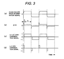
- Figs. 3(a), 3(b), 3(c) and 3(d) illustrate the quasi-square wave determination signal ⁇ Id**, ⁇ Vd waveform, (r1 + r2') synchronization signal and L ⁇ synchronization signal, respectively.
- the first order delay circuit 102 ( Fig. 2 ) causes a delay in the rise and fall time of the quasi-square wave determination signal ⁇ Id** as shown in Fig. 3(a) .
- the ⁇ Vd signal in Fig. 3(b) consists of a transient period (delay time) TL and a given remaining time Tr until the sine reverses.
- the synchronization signal in Fig. 3(c) from the (r1 + r2') synchronization signal generator 103 ( Fig.
- the resistance determination block 110 multiplies the voltage variation ⁇ Vd which outputted from the d-axis current controller 20 by the output of the (r1 + r2') synchronization signal generator 103, and the multiplication product is integrated by the integrator 105 to determine the resistance variation ⁇ (r1 + r2').
- a combined resistance separator 106 separates the determined resistance variation ⁇ (r1 + r2') into ⁇ r1 and ⁇ r2'. Specifically, the separation can be carried out using either the equations (20), (21) or the equations (22), (23) by assuming that the variation rate of the primary resistance r1 is equal to that of the secondary resistance r2.
- r1* and r2* are respectively primary and secondary resistance reference values.
- the leakage induction determining block 120 multiplies the ⁇ Vd value by the output of the L ⁇ synchronization signal generator 104 and integrates the multiplication product at a multiplier 107 to determine the leakage induction variation ⁇ L ⁇ .
- the output signal in Fig. 3(d) from the L ⁇ synchronization signal generator 104 ( Fig. 2 ) is synchronized with the quasi-square wave determination signal shown in Fig. 3(a) which is generated by the square wave generator 101 ( Fig. 2 ). And this output signal is, during the ⁇ Vd transient period TL, is +1 when the square wave signal is positive and -1 when negative, while it is 0 during the remaining period Tr other than the ⁇ Vd transient period.
- the voltage compensation value ⁇ Vd** corresponding to the (r1 + r2') related motor parameter is calculated by adding the (r1* + r2'*) set value 26 and the determined resistance variation ⁇ (r1 + r2') and multiplying the sum by the determination signal ⁇ Id**.
- the voltage compensation value ⁇ Vd** corresponding to the leakage inductance L ⁇ is calculated by adding the L ⁇ * set value 27 and the determined leakage inductance variation ⁇ L ⁇ and multiplying the sum by the output of a differentiator 108 which is the derivative of the ⁇ Id** value.
- the voltage compensation value ⁇ Vd** is calculated from: the sum of the (r1* + r2'*) set value and the ⁇ (r1 + r2') related integral (output of the integrator 105); and the sum of the set value L ⁇ * and the L ⁇ * related integral (output of the integrator 107), and the resulting voltage compensation value is added at the voltage command value calculator 13. Since the ⁇ Vdh value converges to zero with time, the ⁇ (r1 + r2') related and ⁇ L ⁇ related integrals converge to certain values, and thereby the resistance variation ⁇ (r1 + r2') and leakage inductance variation ⁇ L ⁇ can be determined independently of each other.
- the ⁇ r1 and Ar2' values are separated at the combined resistance separator 106, and the leakage inductance variation ⁇ L ⁇ is outputted from the integrator 107 to determine the motor parameters, and these values are then added to the set values r1*, r2'* and L ⁇ * respectively to reset the control parameters of the controller 300.
- the control parameters of the controller 300 are set based on the determined motor parameters.
- the resistance variations ⁇ r1 and ⁇ r2' and the leakage inductance variation ⁇ L ⁇ which are the determined motor parameter variations, are each added to the corresponding reference value to reset the control parameters of the controller 300, thus preventing degradation in controllability of the motor's velocity and torque which may be caused by inappropriate setting of motor parameters or variation in such parameters during operation.
- the first embodiment described above uses the square wave generator 101 to add the quasi-square wave signal (quasi-rectangular wave signal) to the d-axis current command value, a sinusoidal wave signal may be added.
- a determination signal generator 200 is configured with a sinusoidal wave generator 201, while a (r1 + r2') synchronization signal generator 203 and a L ⁇ synchronization signal generator 204 are different from those used in the first embodiment of Fig. 2 .
- the other parts are identical to corresponding parts in Fig. 2 , and therefore are numbered in the same manner as Fig. 2 and will not be described again here. The operating principle will first be described.
- Idh in the equation (17) is a sinusoidal wave Ids sin ⁇ t having an amplitude of Ids and an angular frequency of ⁇
- the equation (17) is modified to an equation (24).
- ⁇ Vds ⁇ r ⁇ 1 + r ⁇ 2 ⁇ ⁇ ⁇ Ids ⁇ sin ⁇ t + ⁇ L ⁇ ⁇ ⁇ ⁇ Ids ⁇ cos ⁇ t
- a voltage compensation value ⁇ Vd** is calculated from: the sum of an (r1* + r2'*) set value 26 and the ⁇ (r1 + r2') related integral; and the sum of a L ⁇ * set value 27 and the ⁇ L ⁇ related integral, and the resulting voltage compensation value is then added at a voltage command value calculator 13. Since, the ⁇ Vds value converges to zero with time, the ⁇ (r1 + r2') related and ⁇ L ⁇ related integrals converge to certain values, and thereby the resistance variation ⁇ (r1 + r2') and leakage inductance variation ⁇ L ⁇ can be determined independently of each other. This is the operating principle. The embodiment will presently be described with reference to Figs. 4 and 5 .
- the determination signal generator 200 includes the sinusoidal wave generator 201, which outputs a sinusoidal wave of a predetermined amplitude to generate a determination signal ⁇ Id**.
- the determination signal ⁇ Id** is added to the d-axis current command value to provide a current reference signal.
- a d-axis current controller 20 inputs a deviation between a d-axis current and the current reference signal and outputs a voltage variation ⁇ Vd, which is inputted to the parameter determining unit 1 to determine the resistance variation ⁇ (r1 + r2') and leakage inductance variation ⁇ L ⁇ of an induction motor 30 independently of each other.
- Figs. 5(a), 5(b), 5(c) and 5(d) illustrate the sinusoidal wave determination signal, ⁇ Vd waveform, (r1 + r2') synchronization signal and L ⁇ synchronization signal, respectively.
- a resistance determination unit 110 ( Fig. 4 ) multiplies the voltage variation ⁇ Vd outputted from the d-axis current controller 20 by the output of the (r1 + r2') synchronization signal generator 203 ( Fig. 4 ), and the multiplication product is integrated by an integrator 105 to determine the resistance variation ⁇ (r1 + r2').
- the output signal of the (r1 + r2') synchronization signal generator 203 Fig.
- this output signal is +1 when the sine of the sinusoidal wave signal is positive and -1 when the sine is negative.
- the leakage induction variation ⁇ L ⁇ can be determined by a leakage induction determining block 120, which multiplies the ⁇ Vd value by the output of the L ⁇ synchronization signal generator 204 and integrates the multiplication product at a multiplier 107.
- the output signal of the L ⁇ synchronization signal generator 204 leads the sinusoidal wave by ⁇ /2 as shown in Fig. 5(d) .
- this output signal is +1 when the slope of sinusoidal wave signal is positive and -1 when the slope is negative.
Landscapes
- Engineering & Computer Science (AREA)
- Power Engineering (AREA)
- Control Of Ac Motors In General (AREA)
Description
- The present invention relates to induction motor controllers using motor parameters.
- The rotating torque of an induction motor is produced by an interaction between a rotating magnetic field generated by its stator winding and an induced current flowing through its rotor winding. The rotor and stator windings are represented by a motor equivalent circuit, in which the motor parameters of primary and secondary resistances and leakage inductance determine the voltage-current characteristics of the induction motor.
- In
US 6 281 659 B an induction motor drive system with/without a speed sensor is disclosed where resistance values are stably and accurately estimated during the operation of the motor regardless of the operating conditions such as a speed, a load, etc. and of a particular combination of parameters. A suitable point Pr is taken inside a current locus on a stator current vector plane, and a measured current is and an observed current is' are referenced from this point Pr. The difference between the magnitudes of two vectors is and is' is associated with an error of a rotor resistance Rr, while the difference between phase shifts is associated with an error of a stator resistance Rs. - The
US 5 859 521 A is directed to provide a trans-vector controller for an alternating current ("AC") motor that facilitates operating the secondary resistance of the AC motor without experimentally rotating the AC motor. In a preferred embodiment, the variable speed control circuit, including a secondary resistance value generating device, changes the direct current ("DC") exciting current and operates the secondary resistance of an induction motor by superimposing an AC signal with small amplitude outputted from a AC signal generator onto a reference current value immediately before the start of the induction motor in the state of DC excitation -
US 5 880 572 A refers to a variable-speed control apparatus which computes the leakage inductance of an AC motor, correctly compensates the leakage inductance, and controls the variable speed of the AC motor. The variable-speed control apparatus has an AC signal generation circuit for generating an AC signal, and obtains a leakage inductance calculation value of the AC motor based on the AC signal and the measured actual current value. The differential value of the summation of a current command value and the AC signal is multiplied by the leakage inductance calculation value to generate a signal for use in compensating the voltage drop caused by the leakage inductance, and added to a voltage command value to cancel the deviation between the actual current value and the M-axis current command value and to obtain the second voltage command value. The second voltage command value is converted into a 3-phase voltage command value and used in controlling the AC motor, and the voltage drop caused by the leakage inductance can be compensated. - Methods for controlling a motor described in the
Japanese Patent Laid-open Nos. Hei 6 (1994)-105580 Hei 6 (1994)-284771 Hei 8 (1996)-317698 Japanese Patent Laid-open Nos. Hei 6 (1994)-105580 Hei 6 (1994)-284771 Hei 8 (1996)-317698 Hei 9 (1997)-191699 - However, an actual motor parameter varies with the temperature of a motor. A deviation of the actual value of a motor parameter from the parameter set in a controller caused by this motor parameter variation may degrade the controllability or destabilize the control. In addition, the method of the above Patent Documents 4 has a problem in that each motor parameter is not determined until all of them have been determined, thus requiring longer time for the determination. Further, if the operating condition required for measuring motor parameters is not satisfied, the motor parameters cannot be determined, which may result in a poorer accuracy depending on the operating condition. Furthermore, the controller perform the determination based on a variation in the basic wave component of the d-axis current; therefore, the determination accuracy is degraded in the event of an error introduction caused by the dead time of the inverter or on-state voltage drop in the inverter devices because such error cannot be separated from the parameter variation.
- An object of the present invention is to provide an induction motor controller which overcomes such problems and can prevent degradation in controllability due to variation in an actual value of a motor parameter.
- This object is achieved by the induction motor controller of
claim 1. Preferred embodiments of the invention are characterized in the sub-claims. - The present invention can prevent degradation in controllability due to variation in an actual value of a motor parameter.
- Embodiments of the invention are now described with reference to the drawings in which:
-
Fig. 1 is a block diagram of a induction motor according to a first embodiment of the invention: -
Fig. 2 is a block diagram of a parameter determining unit of a first embodiment of the invention; -
Fig. 3 illustrates waveforms of a square wave determination signal and synchronization signals of a first embodiment of the invention; -
Fig. 4 is a block diagram of a parameter determining unit of a second embodiment of the invention; -
Fig. 5 illustrates waveforms of a sinusoidal wave determination signal and synchronization signals of a second embodiment of the invention; and -
Fig. 6 illustrates waveforms of a triangular wave determination signal and synchronization signals of a modification of the invention. - An induction motor controller according to a first embodiment of the invention will be described with reference to
Figs. 1 ,2 and3 . - In a block diagram of
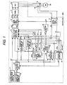
Fig. 1 , a three-phase induction motor 30 is connected to an induction motor controller 300 where acurrent detector 14 detects a current I of theinduction motor 30. Thecurrent detector 14 detects currents in two of the U phase, V phase, and W phase. Here, the current in the other phase can be uniquely determined because the sum of the currents in the three phases is equal to zero. - The induction motor controller 300 controls an inverter (INV) 10 so as to drive the
induction motor 30 to achieve target values of a d-axis current command value Id* generated by an exciting currentcommand value generator 17 and a velocity command value ωr* generated by a velocitycommand value generator 18. The function of the inverter 10 is provided by power switching devices, while the below described functions are each realized by: a computer including a CPU (Central Processing Unit), ROMs (Read Only Memory), RAMs (Random Access Memory) and others; and a program stored in a ROM, a RAM or the like. - The rotating torque of the
induction motor 30 is produced by an interaction between a rotating magnetic field generated by its stator winding and an induced current flowing through its rotor winding when it slips. The coordinate converter 12 inputs: a d-axis voltage command value Vd* for the d-axis which is the exciting axis (magnetic flux axis); and a q-axis voltage command value Vq* for the q-axis perpendicular to the d-axis, and generates three-phase voltage command values Vu*, Vv* and Vw*, based on which a PWM (Pulse Width Modulation) converter 11 PWM controls the inverter 10 to output voltages to theinduction motor 30. - The d-axis voltage command value Vd* and q-axis voltage command value Vq* are generated from multiple signals including: a q-axis current command value Iq* obtained at a
velocity controller 19 from a rotational velocity estimate ωr^ and the velocity command value ωr*; the d-axis current command value Id*; a voltage difference ΔVd outputted from a d-axiscurrent controller 20; and a voltage difference ΔVq outputted from a q-axiscurrent controller 21. Here, the voltage variation ΔVd is generated from a deviation of a d-axis motor current ld from a d-axis current reference signal that is the sum of the Id* value and a periodically varying periodic signal ΔId**, while the voltage variation ΔVq is generated from a deviation of a q-axis motor current Iq from the Iq* value. And, the motor is controlled such that ld = Id* and lq = Iq*. - In addition, a
coordinate converter 15 calculates the d-axis motor current Id and q-axis current motor Iq from the motor current I, while avelocity estimator 22 estimates an angular velocity of theinduction motor 30 from the q-axis voltage variation ΔVq, an angular frequency command value ω1*, and the Iq* and Iq values and outputs the angular velocity estimate ωr^. Aslip velocity estimator 23 calculates a motor slip velocity estimate ωs^ from the Id* and Iq* values, while afrequency calculator 24 inputs the ωr^ value and slip velocity estimate ωs^, calculates an equation: ω1* = ωr^ + ωs^, and outputs the angular frequency command value ω1*. Further, anintegrator 16 converts the ω1* value to an angle command value θ*, which is in turn inputted to thecoordinate converters - A
parameter determining unit 1, which is a configuration feature of the embodiment, generates the periodic signal ΔId**, which is used together with the output signal ΔVd to determine variations in themotor 30 parameters. The motor parameters include a primary resistance r1, secondary resistance r2' converted to the primary side and leakage inductance Lσ in the equivalent circuit of theinduction motor 30. Further, theparameter determining unit 1 outputs a voltage compensation value ΔVd** based on the determined motor parameters. Furthermore, the motor parameter variations Δ(r1 + r2'), Δr1, Δr2' and ΔLσ determined by theparameter determining unit 1 are, each time the parameters vary, inputted to a voltagecommand value calculator 13, thevelocity estimator 22 and theslip velocity estimator 23 to reset (re-correct) the motor parameters. - Each of these functions will be now described.
- The d-axis current command value Id*, q-axis current command value Iq* and voltage variations ΔVd and ΔVq are inputted to the voltage
command value calculator 13, which in turn calculates the output voltage command values Vd* and Vq* using equations (1) and (2).

- Here, r1*, Lσ*, M*, L2*, and φ2d* are, respectively, a primary resistance set value, leakage inductance set value, mutual inductance set value, secondary inductance set value and d-axis secondary magnetic flux command value of the
induction motor 30. - On the other hand, the
induction motor 30 generally satisfies equations (3), (4), (5) and (6). In the equations, symbols without an asterisk (*) represent actual values of the motor parameters. And, r2, r2' in the equation (7), φ2q, ωs, T2 in the equation (8) and s represents a secondary resistance, the secondary resistance converted the primary side, a q-axis secondary magnetic flux, a slip velocity, a motor secondary time constant and the differential operator, respectively. And, L2, M and Lσ are a secondary inductance, a mutual inductance and the leakage inductance, respectively.


- In this case, under a steady state (s = 0), substituting the equation (9) into the equation (5) gives an equation (10) for the d-axis secondary magnetic flux φ2d.

- In addition, combining the equations (6) and (10) yields an equation (11) for the slip velocity estimate ωs^.

- The
slip velocity estimator 23 outputs the slip velocity estimate ωs^ of theinduction motor 30 according to the equation (11). - The
velocity estimator 22 calculates the angular velocity estimate ωr^ from the values of Iq and Iq* and the q-axis voltage variation ΔVq according to the equation (12).
- Here, T1 is a control parameter for determining an estimated response.
- The d-axis motor voltage Vd and q-axis motor voltage Vq of the
induction motor 30 respectively satisfy equations (13) and (14) derived from the equations (3), (4), (5) and (6).

- When Id* = Id and Iq* = Iq, the equations (1) and (2) expressing the (reference) voltage command values are equal to the equations (13) and (14) expressing the motor voltages, respectively. Therefore, the d-axis voltage variation ΔVd and q-axis voltage variation ΔVq are compensated by the d-axis
current controller 20 and q-axiscurrent controller 21 in response to a deviation of the d-axis current Id from the d-axis current command value Id* and a deviation of the d-axis current Iq from the q-axis current command value Iq*, respectively. These are the basic operations of a sensorless vector control with a current controller. - The operating principle of the
parameter determining unit 1 will now be described. - When determining the motor parameters, a periodic current variation command value Idh* is added to the d-axis current command value Id*; therefore, the voltage variation ΔVd, which is the output the d-axis
current controller 20, is the sum of the basic voltage variation ΔVdb and the periodic voltage variation ΔVdh (= ΔVd**.) As will be described later, if the ΔVd value is integrated, the ΔVdb value has no influence on the determination of the motor parameters. Therefore, considering only factors influencing on the parameter determination yields an equation (15) for the output Vd* of the voltagecommand value calculator 13.
- On the other hand, the equation (13) can be reduced to an equation (16) expressing the ldh related component of the d-axis motor voltage Vd.

- When Idh* = Idh, the equations (15) and (16) yields an equation (17) for the periodic voltage variation ΔVdh outputted from the d-axis
current controller 20.
- Here, Δ (r1+ r2') and ΔLσ are expressed by equations (18) and (19) respectively.


- That is, when there arises a variation Δ (r1 + r2') from the reference value (r1 + r2') or a variation ΔLσ from the reference value Lσ, the d-axis
current controller 20 generates a variation ΔVdh by an amount corresponding to the variation Δ (r1 + r2') or ΔLσ. In the equation (17), the ΔVdh value includes the values of Δ (r1 + r2') and ΔLσ. The present embodiment determines the values of Δ (r1 + r2') and ΔLσ from the ΔVd value independently of each other. - As seen from the equation (17), when Idh ≠ 0, the ΔVdh value includes the Δ (r1 + r2') related component. Further, it includes the ΔLσ related component when the Idh value changes, while the ΔLσ related component is equal to 0 when the Idh value stays constant. Therefore, if a quasi-square wave signal is superimposed on the d-axis current command value as a periodically varying current component, the Δ (r1 + r2') related component is dominant in the ΔVdh value during the Idh value stays substantially constant. On the other hand, the ΔLσ related component is dominant during the ΔVdh value changes (i.e., rises or falls.)
- If the ΔVdh value is integrated over the period during which the quasi-square wave signal is substantially constant and its sine is positive, while the negative of the ΔVdh value (-ΔVdh) is integrated over the above period and the sine is negative, then the Δ(r1 + r2') related component can be integrated over time. On the other hand, if the values of ΔVdh and -ΔVdh are integrated over the period during which the quasi-square wave signal changes in a similar manner, then the ΔLσ related component can be integrated over time.
- Since the motor parameters are determined by integrating the ΔVdh value over time, the basic voltage variation ΔVdb (DC component) is cancelled, thus preventing introduction of error caused by the dead time of the inverter 10 or on-state voltage drop in the inverter 10 devices. This removes the aforementioned problem of reduced accuracy.
- The
parameter determining unit 1 uses: the sum of the (r1* + r2'*) set value and the Δ (r1 + r2') related integral; and the sum of the Lσ* set value and the ΔLσ related integral to calculate the voltage compensation value ΔVd**, which is added to the voltagecommand value calculator 13. Since, the ΔVdh value converges to zero with time, the Δ (r1 + r2') related and ΔLσ related integrals converge to certain values, and thereby the resistance variation Δ (r1 + r2') and leakage inductance variation ΔLσ can be determined independently of each other. Here, the reason why the ΔVdh value converges to zero is that the ΔVd** value compensates the current deviation Δid (≠ Δid**) caused by parameter variations, and causes the Δid value to become equal to the Δid** value. This will be described in detail below. -
Fig. 2 illustrates a detailed configuration of theparameter determining unit 1, which is a feature of the embodiment.Fig. 2 illustrates operations of the d-axiscurrent controller 20, a d-axis circuit of theinduction motor 30, a main operational block of the voltagecommand value calculator 13 and theparameter determining unit 1. - Focusing attention to the d-axis circuit, the
induction motor 30 is represented by a delay element which inputs the d-axis voltage command voltage Vd*, outputs the d-axis motor current Id, and includes the primary resistance r1, the secondary resistance r2' converted to the primary side and the leakage inductance Lσ. The current Id is fed back to the input of the d-axiscurrent controller 20 and controlled to achieve a target value of the current reference signal that is the sum of the current command value Id* and the periodic signal ΔId**. - A value r1*25, value (r1* + r2'*) 26 and value Lσ* 27 are a primary resistance set value, a set value for the sum of the primary resistance and the secondary resistance converted to the primary side and a leakage inductance set value, respectively. The
parameter determining unit 1 includes adetermination signal generator 100,resistance determining block 110, leakageinductance determining block 120, (r1 + r2')synchronization signal generator 103 and Lσsynchronization signal generator 104. - The
determination signal generator 100 includes asquare wave generator 101 and a firstorder delay circuit 102, where thesquare wave generator 101 outputs the square wave signal (rectangular wave signal), which is inputted to the firstorder delay circuit 102. The firstorder delay circuit 102 multiplies the input signal by a predetermined gain Kh and others and generates the quasi-square wave determination signal ΔId** which is a periodic signal. The determination signal ΔId** is added to the d-axis current command value Id* to generate the current reference signal. Further, theparameter determining unit 1 uses theresistance determining block 110 and leakageinductance determining block 120 to determine the resistance variation Δ (r1 + r2') and leakage inductance variation ΔLσ of theinduction motor 30 independently of each other. -
Figs. 3(a), 3(b), 3(c) and 3(d) illustrate the quasi-square wave determination signal ΔId**, ΔVd waveform, (r1 + r2') synchronization signal and Lσ synchronization signal, respectively. The first order delay circuit 102 (Fig. 2 ) causes a delay in the rise and fall time of the quasi-square wave determination signal ΔId** as shown inFig. 3(a) . The ΔVd signal inFig. 3(b) consists of a transient period (delay time) TL and a given remaining time Tr until the sine reverses. The synchronization signal inFig. 3(c) from the (r1 + r2') synchronization signal generator 103 (Fig. 2 ) is synchronized with the quasi-square wave determination signal inFig. 3(a) , and it is 0 during the ΔVd transient period TL, while, during the remaining period Tr, it is +1 when the determination signal is positive and -1 when negative. - Turning to
Fig. 2 , theresistance determination block 110 multiplies the voltage variation ΔVd which outputted from the d-axiscurrent controller 20 by the output of the (r1 + r2')synchronization signal generator 103, and the multiplication product is integrated by theintegrator 105 to determine the resistance variation Δ (r1 + r2'). - A combined
resistance separator 106 separates the determined resistance variation Δ (r1 + r2') into Δ r1 and Δ r2'. Specifically, the separation can be carried out using either the equations (20), (21) or the equations (22), (23) by assuming that the variation rate of the primary resistance r1 is equal to that of the secondary resistance r2.


- Here, r1* and r2* are respectively primary and secondary resistance reference values.
- On the other hand, the leakage
induction determining block 120 multiplies the ΔVd value by the output of the Lσsynchronization signal generator 104 and integrates the multiplication product at amultiplier 107 to determine the leakage induction variation ΔLσ. The output signal inFig. 3(d) from the Lσ synchronization signal generator 104 (Fig. 2 ) is synchronized with the quasi-square wave determination signal shown inFig. 3(a) which is generated by the square wave generator 101 (Fig. 2 ). And this output signal is, during the ΔVd transient period TL, is +1 when the square wave signal is positive and -1 when negative, while it is 0 during the remaining period Tr other than the ΔVd transient period. - Turning to
Fig. 2 , the voltage compensation value ΔVd** corresponding to the (r1 + r2') related motor parameter is calculated by adding the (r1* + r2'*) setvalue 26 and the determined resistance variation Δ (r1 + r2') and multiplying the sum by the determination signal ΔId**. On the other hand, the voltage compensation value ΔVd** corresponding to the leakage inductance Lσ is calculated by adding the Lσ* setvalue 27 and the determined leakage inductance variation ΔLσ and multiplying the sum by the output of adifferentiator 108 which is the derivative of the ΔId** value. - Then, the voltage compensation value ΔVd** is calculated from: the sum of the (r1* + r2'*) set value and the Δ (r1 + r2') related integral (output of the integrator 105); and the sum of the set value Lσ* and the Lσ* related integral (output of the integrator 107), and the resulting voltage compensation value is added at the voltage
command value calculator 13. Since the ΔVdh value converges to zero with time, the Δ (r1 + r2') related and ΔLσ related integrals converge to certain values, and thereby the resistance variation Δ (r1 + r2') and leakage inductance variation ΔLσ can be determined independently of each other. In addition, the Δr1 and Ar2' values are separated at the combinedresistance separator 106, and the leakage inductance variation ΔLσ is outputted from theintegrator 107 to determine the motor parameters, and these values are then added to the set values r1*, r2'* and Lσ* respectively to reset the control parameters of the controller 300. In other words, the control parameters of the controller 300 are set based on the determined motor parameters. - As has been described above, according to the embodiment, the resistance variations Δr1 and Δr2' and the leakage inductance variation ΔLσ, which are the determined motor parameter variations, are each added to the corresponding reference value to reset the control parameters of the controller 300, thus preventing degradation in controllability of the motor's velocity and torque which may be caused by inappropriate setting of motor parameters or variation in such parameters during operation.
- Although the first embodiment described above uses the
square wave generator 101 to add the quasi-square wave signal (quasi-rectangular wave signal) to the d-axis current command value, a sinusoidal wave signal may be added. - A parameter determining unit according to a second embodiment of the invention will be described with reference to
Figs. 4 and5 . InFig. 4 , adetermination signal generator 200 is configured with asinusoidal wave generator 201, while a (r1 + r2')synchronization signal generator 203 and a Lσsynchronization signal generator 204 are different from those used in the first embodiment ofFig. 2 . The other parts are identical to corresponding parts inFig. 2 , and therefore are numbered in the same manner asFig. 2 and will not be described again here. The operating principle will first be described. - When Idh in the equation (17) is a sinusoidal wave Ids sinωt having an amplitude of Ids and an angular frequency of ω, the equation (17) is modified to an equation (24).

- Integrating the equation (24) over time from 0 to π/ω gives an equation (25).

- Further, integrating the equation (24) over time from π/(2(ω) to 3π/(2ω) gives an equation (26).

- Therefore, when a sinusoidal wave signal is superimposed on a d-axis current command value as a periodically varying current component, a Δ (r1 + r2') related component can be calculated by integrating the superimposed value from t = nπ/ω to t = (n + 1) π/ω (n = integer), while a ΔLσ related component can be calculated by integrating the superimposed value from t = (n + 1/2) π/ω to t = (n + 3/2) π/ω. Then, a voltage compensation value ΔVd** is calculated from: the sum of an (r1* + r2'*) set
value 26 and the Δ (r1 + r2') related integral; and the sum of a Lσ* setvalue 27 and the ΔLσ related integral, and the resulting voltage compensation value is then added at a voltagecommand value calculator 13. Since, the ΔVds value converges to zero with time, the Δ (r1 + r2') related and ΔLσ related integrals converge to certain values, and thereby the resistance variation Δ (r1 + r2') and leakage inductance variation ΔLσ can be determined independently of each other. This is the operating principle. The embodiment will presently be described with reference toFigs. 4 and5 . - In a
parameter determining unit 1 ofFig. 4 , thedetermination signal generator 200 includes thesinusoidal wave generator 201, which outputs a sinusoidal wave of a predetermined amplitude to generate a determination signal ΔId**. The determination signal ΔId** is added to the d-axis current command value to provide a current reference signal. A d-axiscurrent controller 20 inputs a deviation between a d-axis current and the current reference signal and outputs a voltage variation ΔVd, which is inputted to theparameter determining unit 1 to determine the resistance variation Δ(r1 + r2') and leakage inductance variation ΔLσ of aninduction motor 30 independently of each other. -
Figs. 5(a), 5(b), 5(c) and 5(d) illustrate the sinusoidal wave determination signal, ΔVd waveform, (r1 + r2') synchronization signal and Lσ synchronization signal, respectively. A resistance determination unit 110 (Fig. 4 ) multiplies the voltage variation ΔVd outputted from the d-axiscurrent controller 20 by the output of the (r1 + r2') synchronization signal generator 203 (Fig. 4 ), and the multiplication product is integrated by anintegrator 105 to determine the resistance variation Δ (r1 + r2'). The output signal of the (r1 + r2') synchronization signal generator 203 (Fig. 4 ) is synchronized with the sinusoidal wave as shown inFig. 5(c) . During the period from t = nπ/ω to t = (n + 1) π/ω, this output signal is +1 when the sine of the sinusoidal wave signal is positive and -1 when the sine is negative. - On the other hand, the leakage induction variation ΔLσ can be determined by a leakage
induction determining block 120, which multiplies the ΔVd value by the output of the Lσsynchronization signal generator 204 and integrates the multiplication product at amultiplier 107. The output signal of the Lσsynchronization signal generator 204 leads the sinusoidal wave by π/2 as shown inFig. 5(d) . During the period from t = (n + 1/2) π/ω to t = (n + 3/2) π/ω, this output signal is +1 when the slope of sinusoidal wave signal is positive and -1 when the slope is negative. - The present invention is not limited to the embodiments above, but covers modifications as described below.
- (1) Although quasi-square and sinusoidal wave signals are respectively used for superimposition in the first and second embodiments, a triangular wave, which is a periodic signal, may also be used.
Fig. 6 illustrates an example of a triangular wave determination signal, ΔVd, a (r1 + r2') synchronization signal, and a Lσ synchronization signal. - (2) Although the embodiments above control a motor to acquire a target velocity a velocity command value ωr*, the present invention also includes torque controls.
- (3) Although the embodiments above determine Δ (r1 + r2') which is a variation in the sum of a primary resistance and a secondary resistance converted the primary side, the same results can be obtained by determining (Δr1 +Δr2') which is the sum of: Δr1, a variation in a primary resistance; Δr2', a variation in a secondary resistance converted to the primary side.
- (4) The embodiments above determine: Δ (r1 + r2') which is a variation in the sum of a primary resistance and a secondary resistance converted to the primary side; and ΔLσ which is a variation in a leakage inductance. However, the values of (r1 + r2') and Lσ can be determined if a (r1* + r2'*) set
value 26 and a Lσ* setvalue 27 are set at 0, or such set values are removed.
Claims (6)
- An induction motor controller (300), comprising:a circuit for generating a d-axis current reference signal from a d-axis current command value and a periodically varying periodic signal;a d-axis current controller (20) for controlling a d-axis motor current flowing through an induction motor (30) to be controlled to match the d-axis current reference signal; andparameter determining means (1) for calculating and determining a motor parameter of the induction motor (30) based on a deviation of the d-axis motor current from the d-axis current reference signal, and controlling a voltage applied to the induction motor (30) using a compensation voltage calculated from the calculated and determined motor parameter,wherein a control parameter for controlling the induction motor (30) is set based on the calculated and determined motor parameter,characterized in thatthe periodic signal is a quasi-square wave signal, and wherein the parameter determining means (1) integrates, over a time period during which the amplitude of the quasi-square wave signal is constant, either a value corresponding to the deviation of the d-axis motor current from the d-axis current reference signal or a d-axis voltage variation outputted from the d-axis current controller (20) in order to calculate and determine, as the motor parameter, a combined resistance variation Δ(r1 + r2') or a combined resistance (r1 + r2') where r1 and r2' are respectively a primary resistance and a secondary resistance converted to the primary side, each being the motor parameter.
- The induction motor controller (300) according to Claim 1, wherein the calculation and determination use an output of the d-axis current controller (20) which generates a d-axis voltage variation of the voltage applied to the induction motor (30) in order to control the d-axis motor current to match the d-axis current reference signal based on a deviation of the d-axis motor current from the d-axis current reference signal.
- The induction motor controller (300) according to Claim 1, wherein the periodic signal is a quasi-square wave signal, and wherein the parameter determining means (1) integrates, over a transient time period of the quasi-square wave signal, either a value corresponding to the deviation of the d-axis motor current from the d-axis current reference signal or a d-axis voltage variation outputted from the d-axis current controller (20) in order to calculate and determine, as the motor parameter, a leakage inductance variation of the induction motor (30) converted to the primary side.
- The induction motor controller (300) according to Claim 1, wherein the periodic signal is a sinusoidal wave signal of an angular frequency ω or a triangular wave signal, and wherein the parameter determining means (1) integrates over a time period during which the phase of the sinusoidal or triangular wave signal is from nπ/ω to (n + 1)π/ω (where n is an integer): an operand value, which is either a value corresponding to the deviation of the d-axis motor current from the d-axis current reference signal or a d-axis voltage variation outputted from the d-axis current controller (20), when the sign of the periodic signal is positive; and the negative of the operand value when the sign of the periodic signal is negative in order to calculate and determine, as the motor parameter, a variation in a combined resistance of primary and secondary resistances of the induction motor (30), or the parameter determining means (1) integrates over a time period during which the phase of the sinusoidal or triangular wave signal is from (n + 1/2)π/ω to (n + 3/2)π/ω (where n is an integer), the operand value when the sign of the periodic signal is positive; and the negative of the operand value when the sign of the periodic signal is negative in order to calculate and determine, as the motor parameter, a variation in a leakage inductance of the induction motor (30).
- The induction motor controller (300) according to Claim 1, wherein a primary resistance variation Δr1 and a secondary resistance variation Δr2' converted to the primary side are separately calculated from the combined resistance variation Δ(r1 + r2') using r1* and r2*, where r1, r2', r1* and r2* are respectively a primary resistance, a secondary resistance converted to the primary side, and primary and secondary resistance reference values before a variation.
- The induction motor controller (300) according to Claim 5, wherein the primary resistance variation Δr1 is added to the primary resistance set value r1* before a variation, or the secondary resistance variation Δr2' converted to the primary side is added to the secondary resistance set value r2'* converted to the primary side before a variation to obtain the control parameter.
Applications Claiming Priority (1)
| Application Number | Priority Date | Filing Date | Title |
|---|---|---|---|
| JP2007005578 | 2007-01-15 |
Publications (3)
| Publication Number | Publication Date |
|---|---|
| EP1944862A2 EP1944862A2 (en) | 2008-07-16 |
| EP1944862A3 EP1944862A3 (en) | 2010-06-23 |
| EP1944862B1 true EP1944862B1 (en) | 2011-08-03 |
Family
ID=39367619
Family Applications (1)
| Application Number | Title | Priority Date | Filing Date |
|---|---|---|---|
| EP07016012A Expired - Fee Related EP1944862B1 (en) | 2007-01-15 | 2007-08-14 | Induction motor controller |
Country Status (6)
| Country | Link |
|---|---|
| US (1) | US7671558B2 (en) |
| EP (1) | EP1944862B1 (en) |
| JP (1) | JP5271543B2 (en) |
| KR (1) | KR100925822B1 (en) |
| CN (1) | CN101227166B (en) |
| TW (1) | TW200830689A (en) |
Families Citing this family (14)
| Publication number | Priority date | Publication date | Assignee | Title |
|---|---|---|---|---|
| JP5288957B2 (en) * | 2008-09-10 | 2013-09-11 | 株式会社東芝 | Electric motor control device with resistance compensation function |
| JP4897909B2 (en) * | 2010-07-15 | 2012-03-14 | ファナック株式会社 | Control device for sensorless induction motor with slip frequency correction function |
| JP5537399B2 (en) * | 2010-12-16 | 2014-07-02 | 株式会社日立製作所 | Control device |
| KR101208252B1 (en) * | 2010-12-21 | 2012-12-04 | 성균관대학교산학협력단 | Apparatus and method of generating current command for tracking maximum power point in solar enery generating system |
| KR101209965B1 (en) * | 2010-12-30 | 2012-12-07 | 엘에스산전 주식회사 | System and method for controlling torque of induction motor in electric vehicle |
| KR101221748B1 (en) * | 2011-10-27 | 2013-01-11 | 엘에스산전 주식회사 | Apparatus for estimating rotor time constant of induction motor |
| JP2014147170A (en) * | 2013-01-28 | 2014-08-14 | Shimadzu Corp | Motor drive for vacuum pump and vacuum pump |
| DE102013209319A1 (en) * | 2013-05-21 | 2014-12-11 | Robert Bosch Gmbh | Simulating a field angle between a stator-oriented coordinate system describing an asynchronous machine and a simulated field-oriented coordinate system describing the asynchronous machine |
| US9024569B2 (en) | 2013-06-28 | 2015-05-05 | Eaton Corporation | System and method of rotor time constant online identification in an AC induction machine |
| US10156462B2 (en) * | 2016-11-07 | 2018-12-18 | GM Global Technology Operations LLC | Error correction in a vector-based position sensing system |
| JP6725450B2 (en) * | 2017-04-12 | 2020-07-15 | 日本電産モビリティ株式会社 | Multi-phase electric motor controller |
| CN110247598B (en) * | 2018-03-09 | 2021-05-14 | 宝沃汽车(中国)有限公司 | Compensation method and compensation system of alternating current motor, motor controller and electric automobile |
| CN109305050B (en) * | 2018-09-28 | 2022-06-24 | 上汽通用五菱汽车股份有限公司 | Control method, motor controller, electric vehicle, and computer-readable storage medium |
| CN112994561B (en) * | 2021-01-26 | 2022-09-23 | 浙江工业大学 | Asynchronous motor rotor resistance and leakage inductance identification method based on correlation function method |
Family Cites Families (26)
| Publication number | Priority date | Publication date | Assignee | Title |
|---|---|---|---|---|
| JPS58123394A (en) * | 1982-01-18 | 1983-07-22 | Hitachi Ltd | Controller for ac motor |
| US4808903A (en) * | 1987-04-13 | 1989-02-28 | Hitachi, Ltd. | Vector control system for induction motors |
| JP3076911B2 (en) * | 1988-06-01 | 2000-08-14 | 株式会社日立製作所 | Induction motor secondary resistance calculation method, control method, secondary winding temperature estimation method, protection method, abnormality detection method |
| JP3160778B2 (en) | 1992-09-18 | 2001-04-25 | 株式会社日立製作所 | Inverter-driven motor speed estimation method and device, and motor vector control device using the speed estimation method |
| JP2946157B2 (en) | 1993-03-26 | 1999-09-06 | 株式会社日立製作所 | Induction motor speed control device |
| JP3185604B2 (en) | 1995-05-19 | 2001-07-11 | 株式会社日立製作所 | Induction machine control device |
| JP3240888B2 (en) * | 1995-09-04 | 2001-12-25 | 株式会社日立製作所 | Motor control device, motor control method, and electric vehicle using the same |
| US5880572A (en) | 1996-04-18 | 1999-03-09 | Fuji Electric Co., Ltd. | Variable-speed control method and apparatus for AC motor |
| JP3067681B2 (en) * | 1996-04-18 | 2000-07-17 | 富士電機株式会社 | Variable speed control device for AC motor |
| JP3321356B2 (en) * | 1996-05-20 | 2002-09-03 | 株式会社日立製作所 | Motor control device and control device for electric vehicle |
| JP3111898B2 (en) | 1996-06-10 | 2000-11-27 | 富士電機株式会社 | Variable speed control device for AC motor |
| JP3067659B2 (en) | 1996-11-11 | 2000-07-17 | 株式会社日立製作所 | Control method of induction motor |
| JP3677144B2 (en) * | 1997-10-03 | 2005-07-27 | 株式会社東芝 | Induction motor controller |
| KR100294891B1 (en) * | 1998-07-01 | 2001-07-12 | 윤종용 | Method of estimating leakage inductance of induction motor |
| JP4253903B2 (en) | 1999-03-19 | 2009-04-15 | 富士電機システムズ株式会社 | Induction motor drive and its parameter evaluation method |
| JP3815113B2 (en) * | 1999-04-23 | 2006-08-30 | 株式会社日立製作所 | Induction motor control method |
| JP3520002B2 (en) * | 1999-12-08 | 2004-04-19 | 三菱電機株式会社 | Vector control device for induction motor |
| JP2001238499A (en) * | 2000-02-24 | 2001-08-31 | Hitachi Ltd | Speed control method of induction motor |
| JP4507493B2 (en) * | 2001-07-13 | 2010-07-21 | 三菱電機株式会社 | AC motor speed control device |
| JP3722048B2 (en) * | 2001-11-15 | 2005-11-30 | 日産自動車株式会社 | Motor control device |
| JP3780482B2 (en) * | 2002-03-27 | 2006-05-31 | 株式会社日立製作所 | Induction motor control device |
| JP4410632B2 (en) * | 2004-07-30 | 2010-02-03 | 株式会社日立製作所 | Induction motor control method, control device, iron and non-ferrous equipment, railway vehicle, winder, ship, machine tool, paper machine equipment and transport equipment |
| JP4455245B2 (en) * | 2004-09-22 | 2010-04-21 | 三菱電機株式会社 | Vector control device for induction motor |
| JP4581739B2 (en) * | 2005-02-25 | 2010-11-17 | 株式会社日立製作所 | Electric motor drive |
| KR20070048522A (en) * | 2005-11-04 | 2007-05-09 | 삼성전자주식회사 | Apparatus for estimating stator resistance of motor and method thereof |
| JP4699923B2 (en) * | 2006-03-13 | 2011-06-15 | 株式会社日立産機システム | Induction motor driving apparatus and method |
-
2007
- 2007-08-14 EP EP07016012A patent/EP1944862B1/en not_active Expired - Fee Related
- 2007-08-15 TW TW096130164A patent/TW200830689A/en not_active IP Right Cessation
- 2007-08-22 KR KR1020070084389A patent/KR100925822B1/en active IP Right Grant
- 2007-08-23 CN CN2007101427748A patent/CN101227166B/en not_active Expired - Fee Related
- 2007-08-23 US US11/843,686 patent/US7671558B2/en not_active Expired - Fee Related
-
2008
- 2008-01-11 JP JP2008003802A patent/JP5271543B2/en not_active Expired - Fee Related
Also Published As
| Publication number | Publication date |
|---|---|
| JP5271543B2 (en) | 2013-08-21 |
| CN101227166A (en) | 2008-07-23 |
| US7671558B2 (en) | 2010-03-02 |
| JP2008199881A (en) | 2008-08-28 |
| US20080169783A1 (en) | 2008-07-17 |
| TWI358888B (en) | 2012-02-21 |
| TW200830689A (en) | 2008-07-16 |
| KR20080067275A (en) | 2008-07-18 |
| EP1944862A3 (en) | 2010-06-23 |
| EP1944862A2 (en) | 2008-07-16 |
| KR100925822B1 (en) | 2009-11-06 |
| CN101227166B (en) | 2011-05-11 |
Similar Documents
| Publication | Publication Date | Title |
|---|---|---|
| EP1944862B1 (en) | Induction motor controller | |
| JP5130031B2 (en) | Position sensorless control device for permanent magnet motor | |
| EP1617552B1 (en) | Drive control apparatus and method of alternating current motor | |
| US9438156B2 (en) | Motor control device and motor control method | |
| EP1998435B1 (en) | Method and system for estimating rotor angular position and rotor angular velocity at low speeds or standstill | |
| US9178458B2 (en) | Controller of AC motor | |
| EP2827493B1 (en) | Device for controlling electric motor and method for controlling electric motor | |
| EP2001122B1 (en) | Electric motor control device | |
| EP2757670A1 (en) | Method and apparatus for controlling power converter with inverter output filter | |
| EP2698916A2 (en) | Motor control apparatus and motor control method | |
| EP2228896B1 (en) | Torque controller for permanent magnet synchronous motor | |
| EP1401093A2 (en) | Position-sensorless motor control method and apparatus | |
| US20170264227A1 (en) | Inverter control device and motor drive system | |
| EP2173027A2 (en) | Control device for induction motor | |
| EP2093878B1 (en) | Controller of ac rotating machine | |
| US7072790B2 (en) | Shaft sensorless angular position and velocity estimation for a dynamoelectric machine based on extended rotor flux | |
| EP3267577A1 (en) | Power conversion device and method for controlling same | |
| EP2731261A2 (en) | Apparatus for estimating parameter in induction motor | |
| JP4583257B2 (en) | AC rotating machine control device | |
| EP1326325B1 (en) | Method of extending the operating speed range of a rotor flux based MRAS speed observer in a three phase AC induction motor | |
| JP2006197712A (en) | System and method for driving synchronous motor | |
| JP6135713B2 (en) | Motor control device, magnetic flux command generation device, and magnetic flux command generation method | |
| KR20050104366A (en) | Motor controller and out-of-control detecting method | |
| JP3166525B2 (en) | Induction motor vector control device | |
| EP3214753A1 (en) | Power conversion device and method for controlling power conversion device |
Legal Events
| Date | Code | Title | Description |
|---|---|---|---|
| PUAI | Public reference made under article 153(3) epc to a published international application that has entered the european phase |
Free format text: ORIGINAL CODE: 0009012 |
|
| AK | Designated contracting states |
Kind code of ref document: A2 Designated state(s): AT BE BG CH CY CZ DE DK EE ES FI FR GB GR HU IE IS IT LI LT LU LV MC MT NL PL PT RO SE SI SK TR |
|
| AX | Request for extension of the european patent |
Extension state: AL BA HR MK RS |
|
| PUAL | Search report despatched |
Free format text: ORIGINAL CODE: 0009013 |
|
| AK | Designated contracting states |
Kind code of ref document: A3 Designated state(s): AT BE BG CH CY CZ DE DK EE ES FI FR GB GR HU IE IS IT LI LT LU LV MC MT NL PL PT RO SE SI SK TR |
|
| AX | Request for extension of the european patent |
Extension state: AL BA HR MK RS |
|
| RIC1 | Information provided on ipc code assigned before grant |
Ipc: H02P 21/08 20060101ALI20100520BHEP Ipc: H02P 21/14 20060101AFI20100520BHEP |
|
| 17P | Request for examination filed |
Effective date: 20101008 |
|
| REG | Reference to a national code |
Ref country code: DE Ref legal event code: R079 Ref document number: 602007016206 Country of ref document: DE Free format text: PREVIOUS MAIN CLASS: H02P0021080000 Ipc: H02P0021140000 |
|
| GRAP | Despatch of communication of intention to grant a patent |
Free format text: ORIGINAL CODE: EPIDOSNIGR1 |
|
| AKX | Designation fees paid |
Designated state(s): DE FR GB IT |
|
| RIC1 | Information provided on ipc code assigned before grant |
Ipc: H02P 21/08 20060101ALI20110211BHEP Ipc: H02P 21/14 20060101AFI20110211BHEP |
|
| GRAS | Grant fee paid |
Free format text: ORIGINAL CODE: EPIDOSNIGR3 |
|
| GRAA | (expected) grant |
Free format text: ORIGINAL CODE: 0009210 |
|
| AK | Designated contracting states |
Kind code of ref document: B1 Designated state(s): DE FR GB IT |
|
| REG | Reference to a national code |
Ref country code: GB Ref legal event code: FG4D |
|
| REG | Reference to a national code |
Ref country code: DE Ref legal event code: R096 Ref document number: 602007016206 Country of ref document: DE Effective date: 20110929 |
|
| PLBE | No opposition filed within time limit |
Free format text: ORIGINAL CODE: 0009261 |
|
| STAA | Information on the status of an ep patent application or granted ep patent |
Free format text: STATUS: NO OPPOSITION FILED WITHIN TIME LIMIT |
|
| 26N | No opposition filed |
Effective date: 20120504 |
|
| REG | Reference to a national code |
Ref country code: DE Ref legal event code: R097 Ref document number: 602007016206 Country of ref document: DE Effective date: 20120504 |
|
| REG | Reference to a national code |
Ref country code: FR Ref legal event code: PLFP Year of fee payment: 10 |
|
| REG | Reference to a national code |
Ref country code: FR Ref legal event code: PLFP Year of fee payment: 11 |
|
| REG | Reference to a national code |
Ref country code: FR Ref legal event code: PLFP Year of fee payment: 12 |
|
| PGFP | Annual fee paid to national office [announced via postgrant information from national office to epo] |
Ref country code: FR Payment date: 20200715 Year of fee payment: 14 Ref country code: DE Payment date: 20200804 Year of fee payment: 14 Ref country code: GB Payment date: 20200818 Year of fee payment: 14 |
|
| PGFP | Annual fee paid to national office [announced via postgrant information from national office to epo] |
Ref country code: IT Payment date: 20200713 Year of fee payment: 14 |
|
| REG | Reference to a national code |
Ref country code: DE Ref legal event code: R119 Ref document number: 602007016206 Country of ref document: DE |
|
| GBPC | Gb: european patent ceased through non-payment of renewal fee |
Effective date: 20210814 |
|
| PG25 | Lapsed in a contracting state [announced via postgrant information from national office to epo] |
Ref country code: IT Free format text: LAPSE BECAUSE OF NON-PAYMENT OF DUE FEES Effective date: 20210814 Ref country code: GB Free format text: LAPSE BECAUSE OF NON-PAYMENT OF DUE FEES Effective date: 20210814 Ref country code: FR Free format text: LAPSE BECAUSE OF NON-PAYMENT OF DUE FEES Effective date: 20210831 Ref country code: DE Free format text: LAPSE BECAUSE OF NON-PAYMENT OF DUE FEES Effective date: 20220301 |