EP1948017B1 - Hydration status monitoring - Google Patents
Hydration status monitoring Download PDFInfo
- Publication number
- EP1948017B1 EP1948017B1 EP06790361.7A EP06790361A EP1948017B1 EP 1948017 B1 EP1948017 B1 EP 1948017B1 EP 06790361 A EP06790361 A EP 06790361A EP 1948017 B1 EP1948017 B1 EP 1948017B1
- Authority
- EP
- European Patent Office
- Prior art keywords
- determining
- subject
- segment
- impedance
- indicator
- Prior art date
- Legal status (The legal status is an assumption and is not a legal conclusion. Google has not performed a legal analysis and makes no representation as to the accuracy of the status listed.)
- Active
Links
- 230000036571 hydration Effects 0.000 title claims description 44
- 238000006703 hydration reaction Methods 0.000 title claims description 44
- 238000012544 monitoring process Methods 0.000 title claims description 13
- 238000000034 method Methods 0.000 claims description 100
- 238000005259 measurement Methods 0.000 claims description 73
- 238000012545 processing Methods 0.000 claims description 73
- 238000002847 impedance measurement Methods 0.000 claims description 30
- 210000003722 extracellular fluid Anatomy 0.000 claims description 24
- 210000002977 intracellular fluid Anatomy 0.000 claims description 11
- 238000012937 correction Methods 0.000 claims description 7
- 230000004044 response Effects 0.000 claims description 7
- 239000013598 vector Substances 0.000 claims description 5
- 210000000115 thoracic cavity Anatomy 0.000 claims description 4
- 210000003414 extremity Anatomy 0.000 description 44
- 238000000502 dialysis Methods 0.000 description 36
- 239000012530 fluid Substances 0.000 description 30
- 230000008569 process Effects 0.000 description 29
- 238000004458 analytical method Methods 0.000 description 24
- 206010030113 Oedema Diseases 0.000 description 19
- 206010054880 Vascular insufficiency Diseases 0.000 description 10
- 208000023577 vascular insufficiency disease Diseases 0.000 description 10
- 244000309466 calf Species 0.000 description 9
- 230000000747 cardiac effect Effects 0.000 description 6
- 230000002093 peripheral effect Effects 0.000 description 6
- 210000000476 body water Anatomy 0.000 description 5
- 230000006870 function Effects 0.000 description 5
- 238000010234 longitudinal analysis Methods 0.000 description 5
- 230000002146 bilateral effect Effects 0.000 description 4
- 230000036772 blood pressure Effects 0.000 description 4
- 230000008859 change Effects 0.000 description 4
- 230000008901 benefit Effects 0.000 description 3
- 238000004891 communication Methods 0.000 description 3
- 230000000694 effects Effects 0.000 description 3
- 239000000203 mixture Substances 0.000 description 3
- 238000001356 surgical procedure Methods 0.000 description 3
- 238000012360 testing method Methods 0.000 description 3
- 206010025282 Lymphoedema Diseases 0.000 description 2
- 241001465754 Metazoa Species 0.000 description 2
- 206010037423 Pulmonary oedema Diseases 0.000 description 2
- 238000013459 approach Methods 0.000 description 2
- 206010003119 arrhythmia Diseases 0.000 description 2
- 230000006793 arrhythmia Effects 0.000 description 2
- 230000037396 body weight Effects 0.000 description 2
- 239000000872 buffer Substances 0.000 description 2
- 230000001419 dependent effect Effects 0.000 description 2
- 238000010586 diagram Methods 0.000 description 2
- 210000002683 foot Anatomy 0.000 description 2
- 208000019622 heart disease Diseases 0.000 description 2
- 230000023597 hemostasis Effects 0.000 description 2
- 208000002502 lymphedema Diseases 0.000 description 2
- 230000004048 modification Effects 0.000 description 2
- 238000012986 modification Methods 0.000 description 2
- 238000012806 monitoring device Methods 0.000 description 2
- 230000003071 parasitic effect Effects 0.000 description 2
- 238000012546 transfer Methods 0.000 description 2
- 210000000707 wrist Anatomy 0.000 description 2
- 208000031648 Body Weight Changes Diseases 0.000 description 1
- 206010006187 Breast cancer Diseases 0.000 description 1
- 208000026310 Breast neoplasm Diseases 0.000 description 1
- 208000020446 Cardiac disease Diseases 0.000 description 1
- 241000777300 Congiopodidae Species 0.000 description 1
- 208000028399 Critical Illness Diseases 0.000 description 1
- 206010016803 Fluid overload Diseases 0.000 description 1
- 241000282412 Homo Species 0.000 description 1
- 206010024119 Left ventricular failure Diseases 0.000 description 1
- 208000008589 Obesity Diseases 0.000 description 1
- 241000288906 Primates Species 0.000 description 1
- 206010039163 Right ventricular failure Diseases 0.000 description 1
- 230000002411 adverse Effects 0.000 description 1
- 230000004075 alteration Effects 0.000 description 1
- 210000003423 ankle Anatomy 0.000 description 1
- 238000011871 bio-impedance analysis Methods 0.000 description 1
- 210000001124 body fluid Anatomy 0.000 description 1
- 239000010839 body fluid Substances 0.000 description 1
- 230000004579 body weight change Effects 0.000 description 1
- 230000000739 chaotic effect Effects 0.000 description 1
- 230000018044 dehydration Effects 0.000 description 1
- 238000006297 dehydration reaction Methods 0.000 description 1
- 238000009795 derivation Methods 0.000 description 1
- 229940079593 drug Drugs 0.000 description 1
- 239000003814 drug Substances 0.000 description 1
- 230000002526 effect on cardiovascular system Effects 0.000 description 1
- 238000004070 electrodeposition Methods 0.000 description 1
- 230000002708 enhancing effect Effects 0.000 description 1
- 230000005284 excitation Effects 0.000 description 1
- 238000013213 extrapolation Methods 0.000 description 1
- 235000013861 fat-free Nutrition 0.000 description 1
- 238000001631 haemodialysis Methods 0.000 description 1
- 230000003862 health status Effects 0.000 description 1
- 230000004217 heart function Effects 0.000 description 1
- 230000000322 hemodialysis Effects 0.000 description 1
- 238000010348 incorporation Methods 0.000 description 1
- 230000003834 intracellular effect Effects 0.000 description 1
- 238000011835 investigation Methods 0.000 description 1
- 244000144972 livestock Species 0.000 description 1
- 230000003211 malignant effect Effects 0.000 description 1
- 239000000463 material Substances 0.000 description 1
- 230000007246 mechanism Effects 0.000 description 1
- 238000004377 microelectronic Methods 0.000 description 1
- 238000010606 normalization Methods 0.000 description 1
- 235000020824 obesity Nutrition 0.000 description 1
- 230000008288 physiological mechanism Effects 0.000 description 1
- 230000009467 reduction Effects 0.000 description 1
- 230000006641 stabilisation Effects 0.000 description 1
- 239000000758 substrate Substances 0.000 description 1
- 238000011477 surgical intervention Methods 0.000 description 1
- 208000024891 symptom Diseases 0.000 description 1
- 210000001519 tissue Anatomy 0.000 description 1
- 210000003371 toe Anatomy 0.000 description 1
- 230000002861 ventricular Effects 0.000 description 1
Images


Classifications
-
- A—HUMAN NECESSITIES
- A61—MEDICAL OR VETERINARY SCIENCE; HYGIENE
- A61B—DIAGNOSIS; SURGERY; IDENTIFICATION
- A61B5/00—Measuring for diagnostic purposes; Identification of persons
- A61B5/05—Detecting, measuring or recording for diagnosis by means of electric currents or magnetic fields; Measuring using microwaves or radio waves
- A61B5/053—Measuring electrical impedance or conductance of a portion of the body
- A61B5/0537—Measuring body composition by impedance, e.g. tissue hydration or fat content
-
- A—HUMAN NECESSITIES
- A61—MEDICAL OR VETERINARY SCIENCE; HYGIENE
- A61B—DIAGNOSIS; SURGERY; IDENTIFICATION
- A61B5/00—Measuring for diagnostic purposes; Identification of persons
- A61B5/48—Other medical applications
- A61B5/4869—Determining body composition
- A61B5/4875—Hydration status, fluid retention of the body
- A61B5/4878—Evaluating oedema
-
- G—PHYSICS
- G16—INFORMATION AND COMMUNICATION TECHNOLOGY [ICT] SPECIALLY ADAPTED FOR SPECIFIC APPLICATION FIELDS
- G16H—HEALTHCARE INFORMATICS, i.e. INFORMATION AND COMMUNICATION TECHNOLOGY [ICT] SPECIALLY ADAPTED FOR THE HANDLING OR PROCESSING OF MEDICAL OR HEALTHCARE DATA
- G16H50/00—ICT specially adapted for medical diagnosis, medical simulation or medical data mining; ICT specially adapted for detecting, monitoring or modelling epidemics or pandemics
- G16H50/30—ICT specially adapted for medical diagnosis, medical simulation or medical data mining; ICT specially adapted for detecting, monitoring or modelling epidemics or pandemics for calculating health indices; for individual health risk assessment
-
- A—HUMAN NECESSITIES
- A61—MEDICAL OR VETERINARY SCIENCE; HYGIENE
- A61B—DIAGNOSIS; SURGERY; IDENTIFICATION
- A61B2560/00—Constructional details of operational features of apparatus; Accessories for medical measuring apparatus
- A61B2560/02—Operational features
- A61B2560/0242—Operational features adapted to measure environmental factors, e.g. temperature, pollution
- A61B2560/0247—Operational features adapted to measure environmental factors, e.g. temperature, pollution for compensation or correction of the measured physiological value
- A61B2560/0252—Operational features adapted to measure environmental factors, e.g. temperature, pollution for compensation or correction of the measured physiological value using ambient temperature
Definitions
- the present invention relates to a method and apparatus for determining one or more indicators of a subject's hydration status and in particular to a method and apparatus for monitoring a subject's hydration status during a dialysis procedure.
- bioelectrical impedance This involves measuring the electrical impedance of a subject's body using a series of electrodes placed on the skin surface. Changes in electrical impedance at the body's surface are used to determine parameters, such as changes in fluid levels, associated with the cardiac cycle or oedema.
- US2003/120170 describes a method of determining the dry body weight of a patient undergoing dialysis by means of segmental bioimpedance analysis.
- dry body weight is determined by comparison to the bioimpedance values of normal subjects or by monitoring changes in bioimpedance during dialysis.
- the present invention also provides a method of determining an indication of the hydration status relating to a subject according to claim 3.
- the method includes, In the processing system:
- the reference includes at least one of:
- the indicator is at least one of:
- the method includes, in the processing system:
- the parameter values include R 0 and R ⁇ , wherein:
- the method includes:
- the method includes, in the processing system:
- the method includes, in the processing system:
- the method includes, in the processing system, determining the parameter values by:
- the second body segment and the at least one other body segment are different types of body segment
- the body segments are limbs.
- the body segment includes at least one of:
- the method includes, in the computer system:
- the correction factor is indicative of at least one of:
- the method includes, in the computer system:
- the method includes, in the computer system:
- the method includes, in the computer system:
- the method includes, in the computer system, displaying an indication of at least one of:
- the method includes, in the processing system:
- the method includes, in the processing system:
- the representation is in the form of at least one of:
- the method includes, in the processing system:
- the method includes, in the processing system:
- the electrodes are positioned in accordance with the theory of equal potentials.
- the positioning of the electrodes includes:
- the processing system is coupled to a measuring device, and wherein the method includes, in the processing system:
- the processing system forms part of a measuring device.
- the measuring device includes at least two channels, each channel being adapted to measure the impedance across a respective body segment, and wherein the method includes, in the processing system, causing at least one impedance measurement to be performed using each channel.
- the measuring device includes a processor, and wherein the processor is for:
- the apparatus includes:
- the apparatus is adapted to perform the method of the first broad form of the invention.
- the apparatus includes a monitoring device 1 including a processing system 10 having a processor 20, a memory 21, an input/output (I/O) device 22, and an optional external interface 23, coupled together via a bus 24.
- the external interface can be used to couple the measuring device 1 to one or more peripheral devices 4, such as an external database or computer system, barcode scanner, dialysis machine, any other required sensors, or the like.
- the processing system 10 is coupled to a signal generator 11 and a sensor 12, via a processing module 17, as shown.
- the signal generator 11 and the sensor 12 are selectively coupled to respective electrodes 13A, 13B, 13C, 13D, 15A, 15B, 15C, 15D provided on a subject S, via a multiplexer 18, and connecting leads L, as shown.
- the processing system 10 and processing module 17 are adapted to generate control signals, which cause the signal generator 11 to generate one or more alternating signals, such as voltage or current signals. These signals are then transferred to a selected pair of electrodes 13A, 13B, 13C, 13D by the multiplexer 18, allowing the alternating signals to be applied across a respective segment of the subject S, depending on the position of the selected pair of electrodes 13A, 13B, 13C, 13D.
- the sensor 12 is then connected to selected ones of the electrodes 15A, 15B, 15C, 15D, using the multiplexer 18, allowing the voltage across or current through the respective segment of the subject S to be measured.
- the processing system and processing module 17 are adapted to generate control signals to control the switching of multiplexer 18.
- the sensor 12 transfers appropriate signals to the processing system 10, allowing the impedance of the respective segment of the subject S to be determined, as will be described in more detail below.
- the multiplexer to selectively connect different pairs of the electrodes 13A, 13B, 13C, 13D to the signal generator 11, and pairs of the electrodes 15A, 15B, 15C, 15D to the sensor 12, this allows the impedance across different segments of the subject S to be measured.
- the use of a particular combination of electrodes for measuring a particular body segment is referred to as a channel, and accordingly, it will be appreciated that the above described apparatus provides multi-channel functionality, allowing different body segments to be measured through appropriate switching of the multiplexer.
- multi-channel functionality may be achieved using other configurations, such as by providing a respective processing module 17, signal generator 11 and sensor 12 for each channel.
- the processing system 10 may be any form of processing system which is suitable for generating appropriate control signals and interpreting voltage data to thereby determine the subject's bioelectrical impedance, and optionally the subject's dry mass to aid in dialysis.
- the processing system 10 may therefore be a suitably programmed computer system, such as a laptop, desktop, PDA, smart phone or the like.
- the processing system 10 may be formed from specialised hardware.
- the I/O device may be of any suitable form such as a touch screen, a keypad and display, or the like.
- the processing module 17 is adapted to perform specific processing tasks, to thereby reduce processing requirements on the processing system 10.
- the processing module may be custom hardware, or the like, and in one example is formed from a Field Programmable Gate Array (FPGA), although any suitable processing module, such as a magnetologic module, may be used.
- FPGA Field Programmable Gate Array
- the processing system 10, the processing module 17, the signal generator 11, the sensor 12 and the multiplexer 18 may be integrated into a common housing and therefore form an integrated device.
- the processing system 10 may be connected to the signal generator 11 and the sensor 12 via wired or wireless connections. This allows the processing system 10 to be provided remotely to the signal generator 11 and the sensor 12.
- the signal generator 11 and the sensor 12 may be provided in a unit near, or worn by the subject S, whilst the processing system is situated remotely to the subject S.
- an alternating signal is applied to the subject S using a selected pair of the electrodes 13A, 13B, 13C, 13D. This may be performed either by applying an alternating signal at a plurality of frequencies simultaneously, or by applying a number of alternating signals at different frequencies sequentially. However the frequency range of the applied signals will also depend on the analysis being performed.
- the applied signal is a frequency rich current from a current or voltage source, clamped or limited, so it does not exceed the maximum allowable subject auxiliary current.
- the signal can either be an impulse function or a voltage signal where the current is measured so it does not exceed the maximum allowable subject auxiliary current.
- a potential difference and/or current is measured between a pair of the electrodes 15A, 15B, 15C, 15D.
- buffer circuits are placed in connectors that are used to connect the voltage sensing electrodes 15 to the leads L. This ensures accurate sensing of the voltage response of the subject S, and in particular helps eliminate contributions to the measured voltage due to the response of the leads L.
- a further advantage of this configuration is that the voltage is measured differentially, meaning that the sensor used to measure the potential at each electrode 15 only needs to measure half of the potential as compared to a single ended system. This in turn reduces the potential across the multiplexer 18, thereby greatly reducing capacitive leakage in the multiplexer, resulting in a corresponding increase in accuracy.
- the current measurement system may also have buffers placed in the connectors between the electrodes 13 and the leads L. In this instance, current is also driven or sourced through the subject S symmetrically, which again greatly reduced the parasitic capacitances by halving the common-mode current.
- Another particular advantage of using a symmetrical system is that the micro-electronics built into the connectors for each electrode 13 also reduces parasitic capacitances that arise when the subject S, and hence the leads L move.
- the acquired signal and the measured signal will be a superposition of potentials generated by the human body, such as the ECG, and potentials generated by the applied current.
- the distance between the inner pair of electrodes 15A, 15B, 15C, 15D may be measured and recorded.
- other parameters relating to the subject such as the height, weight, age, sex, health status, any interventions and the date and time on which they occurred and other information, such as current medication, may also be recorded.
- the acquired signal is demodulated to obtain the impedance of the system at the applied frequencies.
- FFT Fast Fourier Transform
- the applied current signals are formed from a sweep of different frequencies, then it is more typical to use a processing technique such as multiplying the measured signal with a reference sine wave and cosine wave derived from the signal generator and integrating over a whole number of cycles. This process totally rejects any harmonic responses and significantly reduces random noise.
- Impedance or admittance measurements are determined from the signals at each frequency by comparing the recorded voltage and current signal.
- the demodulation algorithm will produce an amplitude and phase signal at each frequency.
- an operator of the apparatus positions electrodes 13, 15 on the subject before connecting leads to the electrodes 13, 15 so as to allow the apparatus to measure the impedance of a number of different body segments independently.
- the measuring device 1 will operate to perform impedance measurements by generating an appropriate current sequence and applying this to the subject S via a pair of the electrodes 13A, 13B, 13C, 13D. This is typically performed in sequence for each channel, thereby allowing measurements to be determined for each body segment in turn.
- the measuring device 1 operates to process the impedance measurements so as to determine impedance parameters for each body segment, which can then in turn be analysed to determine indicators of the subject's current hydration status.
- the operator selects that hydration status monitoring is to be performed. This may be required for example in the event that the measuring device 1 is able to perform a number of different types of measurement procedure, and typically involves having an operator select hydration status monitoring from a list of available measurement types.
- the available measurement types are typically determined by the processing system 10 either from the memory 21, or alternatively downloaded via the external interface 23 and are based on predetermined profiles which provide suitable instructions to allow the measuring device 1 to perform the required impedance measurements.
- the processing system 10 may download appropriate firmware into the FPGA 17, allowing the correct impedance measurement process to be performed by the FPGA.
- the measuring device 1 displays a GUI 1000 as shown in Figure 4A .
- the GUI includes a number of fields, shown generally at 1001, which allow data regarding the individual to be provided.
- the data includes information such as name, address, sex, height, weight, limb length or the like.
- an indication of limbs at risk from oedema can be input as shown at 1002, as this can be used in assisting with the analysis.
- the subject record is typically stored in a subject database accessed via the external interface 23, or the like.
- the subject record includes the subject data, and details of any performed impedance measurements for the respective subject, thereby allowing the subject record to form a subject history for use in longitudinal analysis.
- the database is typically a HL7 compliant remote or local database.
- the subject can be provided with a wristband or the like which includes coded data indicative of the subject identifier.
- the measuring device 1 can be coupled to a peripheral device 4 for determining the subject identifier.
- the data may be in the form of a barcode, with the peripheral device 4 being a barcode scanner.
- RFID Radio Frequency ID
- the peripheral device will be a corresponding reader.
- the barcode reader detects the barcode provided on the subject's wrist band, and determines a subject identifier from the detected barcode.
- the barcode reader provides data indicative of the sensed subject identifier to the processing system 10, thereby allowing the processing system 10 to access the subject record from the database.
- the subject identifier could be entered manually by an operator, for example, by using the I/O device 22.
- the measuring device 1 can estimate these from other subject data, such as a the subject height, using anthropometric tables, or the like. These can be customised by the operator of the measuring device, or can be downloaded from a central repository such as the database.
- the processing system will update the GUI 1000 as shown in Figure 4B to display any previously measured impedance values, which may be used as reference data, as will be described in more detail below. Searching, editing and creation of records using the input controls shown generally at 1004.
- the processing system 10 generates a GUI 1010, an example of which is shown in Figure 5A , and which is used in allowing the operator to provide electrode connections.
- the GUI 1010 includes an indication of subject details at 1011.
- a representation 1012 of the subject is provided, which shows general electrode connection points 1013, 1015, indicating where on the subject electrodes 13, 15 should be provided.
- the general arrangement is to provide electrodes on the hand at the base of the knuckles and between the bony protuberances of the wrist, as shown in Figure 5B , and on the feet at the base of the toes and at the front of the ankle, as shown in Figure 5C .
- the current electrodes are provided on one hand and one foot, whilst the voltage electrodes are positioned a set distance apart on a calf or on a bicep.
- This is particularly advantageous as fluid levels in the calf are generally sensitive to changes in the subject's posture, whilst fluid levels in the bicep are relatively posturally invariant. Consequently, comparison of impedance measurements made at a subject's calf and bicep can be useful in detecting the subject's optimal fluid state, whilst taking into account changes in posture, as will be described in more detail below.
- the GUI 1010 also displays details for each limb at 1017A, 1017B, 1017C, 1017D, including an indication of whether the limb is an at risk limb, which is a limb suffering from vascular insufficiency, as caused for example by surgery, obesity, an accident, or the like.
- An example of acquired vascular insufficiency is lymphoedema. This is also shown on the representation 1012 at 1017E.
- An instruction field is shown generally at 1018 and this is provided to display instructions to the operator, with an indication of the selected measurement procedure being shown at 1019, and general measuring device status information being provided at 1020.
- a comments field 1021 can also be used to record comments regarding the measurements made.
- the operator typically updates the weight of the subject in the subject details 1011, which may undergo significant variations over time due to changes in fluid levels within the subject's body.
- the operator may also re-specify the at risk limbs, which is useful when a subject develops further vascular insufficiency in a limb.
- a subject may start off with unilateral vascular insufficiency of the left leg and over time may develop a vascular insufficiency in the right leg. This leg can be recorded at that point as being affected by the use of the "at risk" check boxes.
- the measurement procedure can be initiated by clicking the "ok button" 1022.
- both the weight and comments for each measurement are recorded as part of the corresponding subject record in the subject database. This allows the practitioner to track weight and clinical comments over the period of measurement as well as between different measurement periods.
- the process can be used to measure the dry mass of the subject, not only during a dialysis session, but also between different dialysis sessions, thereby further enhancing the ability of the system to determine any deviation from optimal haemostasis conditions.
- the system can also be used to track additional information, relating to details of potential triggers, such as the subject's food and drink consumption. This coupled with the fact that the system can accurately determine indicators of dry mass and hydration status can be used with trigger information to assess which potential triggers have a material, and adverse effect on the subject and the dialysis process. This in turn allows the triggers to be avoided in future.
- the measuring device 1 optionally checks electrode continuity. This can be achieved based on the theory of equipotentials by comparing potentials measured at different ones of the electrodes.
- the process can measure the potential at different electrodes on a given limb, and these should be identical in accordance with the equipotential theory. In the event that the measured potentials are different, this indicates that there is a fault, such as a problem with the connection to one of the electrodes.
- Any problem with the electrode connections can be indicated to the operator of the measuring device 1 allowing the connection problem to be corrected.
- the process returns to step 430 so that the operator replaces or repositions the electrodes.
- the measuring device 1 optionally measures ECG signals. This can be achieved either through the use of a 5 lead ECG measurement process that utilises the same electrodes as used in measuring the impedance. Alternatively, optional additional leads may be used to allow for recording full 12 lead ECG measurements. If ECG signals are measured, these can be used to monitor an R-R interval trend using chaotic predictors. This can be used to determine a warning of the onset of a malignant or unstable arrhythmia, up to 10 minutes prior to the arrhythmia developing.
- this can be used to monitor cardiac output allowing a warning to be sounded when cardiac output starts to drop during dialysis. This may indicate that the patient will not have adequate cardiac function if more fluid is removed. This can be used to determine the optimum fluid loading for a patient suffering from cardiac disease who also requires dialysis.
- the measuring device 1 optionally measures and trends blood pressure signals.
- the measuring device 1 then performs the required impedance measurements, with general measuring device status information being provided at 1020.
- the monitoring device 1 applies the required current signals to one of the body segments, via a respective one of the channels A, B, measuring the resulting current and voltage across the body segment. This allows instantaneous impedance values to be determined at a number of different frequencies f i , for the respective body segment, which are then stored at step 480.
- the measuring device 1 repeats this for each of the measurement channels, so that impedance measurements are determined for each of the body segments separately.
- the measuring device 1 operates to determine impedance parameters for each body segment.
- the value of the impedance parameters R 0 and R ⁇ may be determined in any one of a number of manners such as by:
- the processing system 10 can also be adapted to test adherence of the measurements to the Cole model.
- the Cole model assumes that the impedance measurements lie on a semi-circular impedance locus. Accordingly, the processing system 10 can determine if the measured values fit a semi-circular locus to thereby determine if the Cole model is satisfied.
- the measured impedance parameter values can be compared to theoretical values derived using the equation (2), to thereby allow the degree of concordance to the Cole model to be determined.
- the GUI 1030 includes subject details at 1031, and a measurement selection inputs 1032. This allows the operator to select measurements of interest, which in this example includes measurements from the left arm. Once the measurements are selected, the processing system 10 displays an overview of parameters determined from the impedance measurements at 1033.
- a number of tabs 1034 can then be used to allow different representations of the measured impedance values to be provided in a window 1035. This includes, for example, producing a complex impedance plot, as shown in Figure 6A . Alternatively the impedance values can be listed as shown in Figure 6B , or plotted as reactance verses frequency or resistance verses frequency as shown in Figures 6C and 6D respectively.
- Frequency controls 1036 are provided to allow impedance measurements above or below threshold limits to be omitted from the displayed results, as shown by threshold markers 1037A, 1037B. Additionally a rejection limit can be applied to discard data points that fall outside a threshold variation from an idealised semi-circular locus provided on the complex impedance plot.
- the impedance parameter values can then be analysed to derive indicators of hydration status.
- the parameters are typically indicative of the extracellular fluid levels in each of the body segments and/or the entire body.
- the indicators are therefore typically indicative of the extracellular fluid volume, or an index based on the ratio of extra- to intra- cellular fluid.
- the resistivity coefficient can be determined at each moment by using a nominal population reference where alpha is measured and then a corresponding resistivity for extracellular fluid is determined. This can also be done using all the variables from a model such as the Cole model to determine the appropriate resistivity. Alternatively this can be manually entered or measured using techniques known to persons skilled in the art.
- the total body water can also be used as an indicator for hydration status.
- this allows impedance measurements across the subject's entire body to be determined.
- the volumes of extracellular and intracellular fluid can be derived from the values R 0 .
- R ⁇ as these depend on the values of the extracellular and intracellular resistance, as discussed above.
- the analysis of the extracellular fluid volumes, the index I and/or the total body water may be achieved in a number of ways, but typically involves comparing the parameters to available references, and accordingly, the process determines if references are available at step 510. If references are available, the measuring device 1 allows the user to select an appropriate reference at step 520.
- the reference can be in the form of earlier data collected for the respective subject, thereby allowing a longitudinal analysis to be performed. This typically requires that data are collected prior to dialysis or other interventions, allowing the measuring device 1 to determine if there are any variations in the subject's extracellular fluid levels during the dialysis process, thereby indicating a change in subject hydration status. This can be performed for each body segment separately, or for the entire body.
- the system may also or alternatively use a normal population database table, which includes reference values obtained from different subjects.
- This database table is essentially a single subject database table into which all measurements of normal population subjects (people without vascular insufficiency) are added.
- FIG. 7A An example of such normal population data displayed using the GUI 1000 is shown in Figure 7A .
- This table then acts as a pool of data from which normalised values for raw impedance data and ratios of impedance data can be generated, allowing comparison with measured values for the subject to be performed.
- This generation of this normalised data is in the form of mean (averaged) values that are selected to be relevant to the test subject.
- the selection is performed based on the subject information and may be performed on the basis of any one of a number of factors, such as age, sex, height, weight, race, interventions, or the like.
- the normalised data drawn from the normal population database will be calculated from measurements from female subjects that are present in the in the normal population database.
- the operator is presented with the GUI 1040 similar to that shown in Figure 7A , which allows the operator to select appropriate records from the normal population table, as shown by the highlighted entry at 1041.
- the reference can be formed from parameter values derived prior to commencement of the dialysis procedure.
- a common example is baseline measurements taken before surgical intervention for breast cancer that can be used to track subjects fluid shifts post surgery by comparison of study measurements to these baseline generated mean values.
- Subject specific baselines can be generated automatically from measurements in the subject's database table. This can in turn be used to provide cut off points for dialysis based on when the measured impedance values or derived indicators approach predetermined impedance or indicator values representing an ideal or optimal fluid level or hydration status.
- Generation of baselines can be achieved using the GUI 1000 shown in Figure 7B , in which the subject's record is displayed. Located on the GUI 1000 are two selection windows 1042, 1043 that are used to define the measurements used from the subject's database table to generate mean data values for comparison to study measurements.
- the process can also be used to add data to the normal population table. This is achieved by performing the measurement process outlined above, and in the event that the subject is healthy, or the subject is a control, such as a family member, importing the data into the normal population table. This can be performed in addition to adding the measurements to the subject record, so that measurements collected from a healthy individual can be used for subsequent longitudinal analysis and/or as a normal population reference.
- the measuring device 1 compares the currently determined indicator to the reference at step 530, and utilises this to generate an indication of the hydrations status which is then displayed at step 540.
- the indicators determined for each body segment are compared to the indicators determined for other ones of the body segments. This allows a relative distribution of fluid within the subject to be monitored, which in turn allows an indication of hydration status to be determined.
- this can be used to determine the presence or absence of oedema.
- the onset of oedema is in turn indicative of variations in the subject's hydration status.
- the analysis of each of the limbs will be influenced by whether the subject is deemed to be at risk of bilateral oedema (i.e. suffering from vascular insufficiency of two limbs).
- the processing system 10 can compare parameters for contra-lateral limbs. This may be achieved for example by determining an index based on a ratio of the extra- to intra- cellular fluid levels in each leg, and then comparing the values determined to assess whether there is difference between the limbs, or against a reference value for that limb, and hence whether there is a likelihood of oedema being present.
- the processing system 10 typically determines the index for each limb. A ratio of the determined index I for different pairs of limbs are then compared, thereby allowing the operator to determine if there is a likelihood of bilateral oedema.
- the measuring device 1 can use this to display a report that is indicative of the hydration status, and/or the presence, absence or degree of oedema.
- the hydration status can be monitored by examining other indicators, such as by examining the impedances values at different selected frequencies.
- this may involve calculating impedance values at specific frequencies in the complex impedance plot.
- This may include theoretical impedance values such as R 0 and R ⁇ , vectors representing the actual measured values, or theoretical values derived at set frequencies, as well as the difference between values of R 0 and R ⁇ .
- the process set out in steps 510 to 540 can involve repeatedly making measurements during the dialysis procedure, and then monitoring the variation in one or more of the above mentioned indicators, such as the value of R ⁇ , the level of extra-cellular fluid, the index I, or the like.
- the process involves monitoring for variation, and in particular, a rate of change of the indicators. When the rate of indicator variation falls below a predetermined threshold, this indicates that the value of the indicator, and hence patient fluid levels, have substantially stabilised, thereby allowing the dialysis procedure to be halted.
- the process involves monitoring changes in the values of indicators such as R 0 , R ⁇ , the difference between R 0 and R ⁇ , vector impedance values, or any other indicator, and then using the rate of variation to control the dialysis process.
- indicators such as R 0 , R ⁇ , the difference between R 0 and R ⁇ , vector impedance values, or any other indicator
- the report is presented using a GUI 1050 that includes subject details shown generally at 1051.
- the GUI includes controls 1052 that allow the operator to select whether reference data is to be used and the nature of the reference data.
- the process will return to step 540 to reassess the nature of the output dependent on the type of reference selected.
- a drop down list is provided to indicate the nature of the parameter that is to be displayed
- checkboxes are provided indicating the limbs for which the parameter is to be displayed.
- a limb of interest and a reference limb can be selected using the check boxes 1054, 1055 as shown.
- the parameters available for charting include:
- the impedance vector plot is a graphical representation of when a subject's measurements move relative to a reference ellipse.
- the reference ellipse can be generated from a 95% confidence interval based on the subject specific baseline data or the normal population data.
- the ellipse can be generated for and displayed for each body segment chosen using the reference limb checkbox.
- the data points displayed are those generated from the study body segment data for the subject.
- the study body segments and reference body segments are chosen using the body segment selector check boxes located underneath the chart.
- Figure 7C shows an example of a fluid loading plot in which the index for left and right legs is compared.
- the index remains within the ellipse shown generally at 1056 highlighting that oedema is not present, and optimum dry mass has been obtained.
- the right arm and left arm are compared as shown in Figure 7D , the values for the ratio comparisons fall outside the reference ellipse 1056 indicating that the right arm is suffering from fluid overload and may have vascular insufficiency.
- the fluid loading plot includes a comparison between limbs, and accordingly, the checkboxes 1053B are not used.
- FIG. 7I An alternative example is shown in Figure 7I .
- the reference ellipse is replaced by reference lines 1071, 1072, defining a "funnel" shaped reference region 1070.
- the reference region may again be based on a 95% confidence interval from the subject's specific baseline data or the normal population data.
- the reference region 1070 is generally more able to take into account variations in physical characteristics between subjects. For example, when a reference ellipse is determined based on population samples, then if a subject has particularly thin limbs, or short fat limbs, then the subject's measured value may fall outside the ellipse, even when the hydration status is normal. However, this does not occur with the reference region 1070.
- a further benefit is that if the subject has some form of oedema and is over hydrated, then this will result in the measured index value that is positioned below the reference line 1072, as shown for example at 1073.
- the measured index is determined to be above the line 1071, as shown for example at 1074, this generally indicates either that the patient is dehydrated, which will require further clinical intervention, or investigation. Alternatively, this indicates that the electrodes have been incorrectly attached to the subject, in which case re-measurement may be required.
- Figure 7E is an example of the ratio of limb ratios in which a ratio of the index for the right arm and right legs is plotted against time. In this instance, it can be seen that a significant variation is present at 1057 indicating an undesirable fluid loading.
- checkboxes 1053B are not used, and are ignored.
- This function will display the ratio of the R 0 of the reference body segment divided by that of a study body segment for each measurement in the subject's database table.
- the index I can also be displayed for each body segment for all measurements in the subjects database table as a chart over time, as shown in Figure 7F .
- the body segments represented on the chart are selected using the control 1053.
- the 1054, 1055 are omitted for clarity.
- the value of R 0 can also displayed for each body segment for all measurements in the subjects database table as a chart over time.
- the value of R ⁇ can also displayed for each body segment for all measurements in the subjects database table as a chart over time.
- the value of R i can also displayed for each body segment for all measurements in the subjects database table as a chart over time.
- the characteristic frequency can also displayed for each body segment for all measurements in the subjects database table as a chart over time.
- ⁇ and ⁇ can also displayed for each body segment for all measurements in the subject's database table as a chart over time.
- SEE standard estimate of errors
- the value of the time delay (Td) associated with each measurement can also displayed for each body segment for all measurements in the subjects database table as a chart over time.
- reference values can also be displayed based either on the normalised population reference or subject specific reference.
- FIG. 7F An example of the use of a subject's specific reference value is shown in Figure 7F .
- the reference value is based on R 0 as shown at 1058. Accordingly, it can be seen that variation of the value R 0 compared to the reference is indicative of oedema.
- the generation of a report by comparison to normal population data will be performed in a similar manner.
- a further feature of the process is the ability to associate event markers with specific measurements in the measurement database table.
- Event markers can provide commented time points that correspond to measurements and points in time. These can be customised by the user to indicate important events that need to be documented on the longitudinal analysis charts. Such events may include, onset date of oedema, the start of medical intervention, the beginning and end of dialysis sessions etc. These markers will be displayed automatically on the longitudinal charts that are a function over time. Event markers can also be shown on charts as shown for example in Figure 7H .
- the processing system 10 therefore selects the types of analysis or representation that is most appropriate for determining the presence or absence of oedema based on the currently available data. This therefore removes the requirement for the operator to make an assessment of which form of report would provide the most accurate indication of the onset of oedema.
- the impedance measurements are collected for each of the limbs, with the assessment of the preferred type of analysis being performed after the measurements have been performed.
- the processing system 10 can be adapted to determine the preferred type of analysis first and then only perform the measurements required in order for the type of analysis to be performed.
- a limited limb analysis can be performed, in which the operator specifies the limbs for which measurements are to be made prior to the measurement process. In this instance, data will only be collected for the limbs of interest.
- profiles can be configured to allow a range of different measurements to be performed.
- the TBW can be used in:
- the measuring device 1 (which is shown as a single channel device for clarity purposes only) is connected to a computer system 3, via the external interface 23 as shown.
- the computer system 3 may be any form of computer system but is typically a desktop, laptop, tablet, PDA, Smart Phone or the like.
- the computer system 3 operates to control the measuring device 1 to perform the measurement procedure.
- the measuring device 1 therefore operates to generate required excitation signals, apply these to the subject, and measure the resulting voltages generated across the subject. Once impedance measurements have been collected, these are transferred via the external interface 23 to the end station 3, which operates to analyse the measured impedance values and generate the appropriate GUIs shown in Figures 5 to 8 .
- the computer system 3 may be connected to the measuring device 1 via a wired, or wireless connection, or alternatively via an appropriate communications network 5, such as an Ethernet, LAN, WAN, the Internet, or the like.
- an appropriate communications network 5 such as an Ethernet, LAN, WAN, the Internet, or the like.
- the operator of the system is generally required to place the measuring device 1 in a predetermined operating mode allowing the computer system 3 to generate any required control signals to activate the measurement process.
- communication between the computer system 3 and the measuring device 1 is typically controlled using the GUI 1060 shown in Figure 10 .
- the GUI includes fields 1061 for defining IP connection details, which allows the computer system 3 to connect to the measuring device, via the external interface 23, via a TCP/IP or other network.
- Fields 1062 are used for defining paths via which the references can be obtained, with the fields 1063 defining details of the database from which the references should be obtained.
- Fields 1064 and 1065 are used to define parameters relating to the impedance analysis to be performed, including default frequency, rejection and time delay limits, as well as reference ranges or the like. Finally fields 1066 are used to define properties of the resulting analysis report.
- GUI can also be used to provide connections to remote databases, such as HL7 compliant subject databases.
- the architecture can be implemented in any one of a number of manners depending on the circumstances in which the measuring device 1 is to be used.
- the selection and/or analysis of the impedance measurements can be performed by a central base station coupled to a number of measuring devices via a suitable communications system, such as a computer network or the like.
- a suitable communications system such as a computer network or the like.
- the base station transfers an indication of this to the respective monitoring thereby causing the measuring device to display the necessary electrode connections.
- the determined measurements are returned to the base station for analysis.
- the subject in performing dialysis it is typical for the subject to be seated in a relined position, in which case fluid is typically distributed unevenly throughout the body (and subject to any specific oedema or the like). If the subject were to stand up or lay down during the process, this results in a significant flow of fluid into or from the lower regions of the subject, such as the calf. Consequently, if measurements are made from the calf, there can be a significant variations in measured impedances associated with the subject's position.
- the measuring device 1 may include an orientation sensor connected to the measuring device 1 as a peripheral device 4, for example.
- the orientation sensor is used to derive information regarding the subject's current orientation, and this could therefore take on any one of a number of forms.
- the orientation sensor could be provided in a subject's bed and operate to determine the subject's orientation based on the bed configuration.
- the orientation sensor may be coupled to the subject, and in particular to the subject's leg or calf, to determine the leg or calf orientation. It will be appreciated from this that any suitable sensor may be used, and in one example, the sensor is at least partially incorporated into the electrodes 15.
- the measuring device 1 can modify the impedance measurement analysis based on the orientation of the subject as determined from the orientation sensor. This can again be achieved in a number of manners.
- the measuring device 1 can be adapted to ensure that indications are only compared to each other if made at the same subject orientation.
- the process may involve taking a baseline reading at each of a number of different orientations. In this instance, the measured readings would then be compared to the corresponding baseline determined for the same subject orientation.
- the fluid levels will also depend on the length of time a subject has been in a given orientation, and again this may be taken into account, for example, by ensuring comparison is made to prior readings in which the subject has maintained a similar posture for a similar amount of time.
- this can be used to determine a correction factor, required to correct for certain orientations. This allows normalisation of any measured values to a specific orientation, allowing the above described analysis to be performed.
- a further variation is to examine differences in indicators between different subject orientations. In this instance, it will be appreciated that if the subject's hydration status is such that the subject has reached an ideal or optimal fluid level, and no further dialysis is required, then changes in orientation will have a reduced effect simply because there is less fluid within the body to be displaced.
- the process involves determining a number of indicators at different subject orientations.
- the measuring device 1 compares the measured indications at each orientation and determines if the difference falls below a threshold. If so, then this indicates that there is minimal variations in fluid between the orientations, and hence that the hydration status is suitable to terminate the dialysis procedure.
- Impedances values measured for a subject include a contribution from the subject's skin, known as a skin impedance.
- the skin impedance is heavily influenced by the hydration levels in the skin, which is in turn dependent on skin temperature.
- the measuring device 1 can use the skin temperature of the subject when analysing impedance values. This can be achieved in a number of ways.
- the skin temperature can be measured using a suitable thermometer, with the skin temperature being supplied to the measuring device 1, via the I/O device 22.
- a skin temperature sensor can be provided as part of the measuring device, either as a peripheral device 4, or through incorporation into suitable electrodes, allowing the measuring device 1 to determine the subject's skin temperature automatically.
- the skin temperature is generally used to generate a calibration factor, which is used to modify the measured impedance values, or subsequently determined indicators, depending on the skin temperature.
- the calibration factor is typically predetermined by analysis of a suitable sample population, across a variety of skin temperatures.
- an effect of the calibration factor is that it can be used to take into account subject ethnicity.
- different reference baselines must be used for subjects having different ethnicities, due to variations in skin impedance.
- by providing a correction factor taking into account both ethnicity and skin temperature allows common baselines to be used by a wider range of subjects having a wider range of ethnicities.
- electrodes are only one of a number of possible electrode arrangements.
- the electrodes may be provided as discrete pads, alternatively a number of electrodes may be provided on a common substrate, for example in the case of band electrodes.
- the electrodes may form part of another related device.
- the voltage measuring electrodes positioned on either the calf or bicep can be incorporated into blood pressure cuff, to allow simultaneous measurement of blood pressure and impedance.
Description
- The present invention relates to a method and apparatus for determining one or more indicators of a subject's hydration status and in particular to a method and apparatus for monitoring a subject's hydration status during a dialysis procedure.
- The reference in this specification to any prior publication (or information derived from it), or to any matter which is known, is not; and should not be taken as an acknowledgment or admission or any form of suggestion that the prior publication (or information derived from it) or known matter forms part of the common general knowledge in the field of endeavour to which this specification relates.
- One existing technique for determining biological parameters relating to a subject, involves the use of bioelectrical impedance. This involves measuring the electrical impedance of a subject's body using a series of electrodes placed on the skin surface. Changes in electrical impedance at the body's surface are used to determine parameters, such as changes in fluid levels, associated with the cardiac cycle or oedema.
- Maintaining hemostasis during hemodialysis is recommended to minimise cardiovascular and other associated risks. Oedema is difficult to detect until the interstitial fluid volume has risen to approximately 30% above normal, whilst severe dehydration can develop before the onset of clinical symptoms. The current method of evaluating hydration status of dialysis patients based on blood pressure and body weight changes over time can be misleading since these parameters are complex variables related to other physiologic mechanisms.
-
US2003/120170 describes a method of determining the dry body weight of a patient undergoing dialysis by means of segmental bioimpedance analysis. In preferred embodiments, dry body weight is determined by comparison to the bioimpedance values of normal subjects or by monitoring changes in bioimpedance during dialysis. - According to the present invention there is provided an apparatus for determining an indication of the hydration status relating to a subject according to
claim 1. The present invention also provides a method of determining an indication of the hydration status relating to a subject according toclaim 3. - Typically the method includes, In the processing system:
- a) comparing the at least one indicator to at least one of:
- i) a predetermined reference;
- ii) an indicator determined for at least one other body segment; and,
- iii) a previously determined indicator; and,
- b) determining an indication of the hydration status using the results of the comparison.
- Typically the reference includes at least one of:
- a) a predetermined threshold;
- b) a tolerance determined from a normal population;
- c) a predetermined range; and,
- d) an indicator previously determined for the subject.
- Typically the indicator is at least one of:
- a) an index (I) of the ratio of extra- to intra-cellular fluid; and,
- b) an extracellular fluid volume.
- Typically the method includes, in the processing system:
- a) determining a plurality of measured impedance values for each body segment, each measured impedance value being measured at a corresponding measurement frequency; and,
- b) determining impedance parameter values based on the plurality of measured impedance values, the indicator being at least partially based on the determined impedance parameter values.
- Typically the parameter values include R0 and R∞, wherein:
- R0 is the resistance at zero frequency; and,
- R∞ is the resistance at infinite frequency.
- Typically the method includes:
- a) monitoring changes over time for at least one of:
- i) R0;
- ii) R∞;
- iii) a difference between R0 and R∞;
- b) a vector indication of an impedance measurement.
- Typically the method includes, in the processing system:
- a) determining values for parameters R0 and R ∞ from the measured impedance values; and,
- b) determining the indicator by calculating the index (I) using the equation:

- Typically the method includes, in the processing system, determining the parameter values using the equation:

- Z is the measured impedance at angular frequency ω,
- τ is a time constant, and
- α has a value between 0 and 1.
- Typically the method includes, in the processing system:
- a) determining the impedance of each body segment at four discrete frequencies; and,
- b) determining values for the parameters by solving the equation using four simultaneous equations.
- Typically the method includes, in the processing system, determining the parameter values by:
- a) determining a complex impedance locus using the measured impedance values; and,
- b) using the complex impedance locus to determine the parameter values.
- Typically the indicator for a body segment is the extracellular fluid volume determined using the equation:

- Where ECV = Extracellular fluid volume
- CSegement = Geometry Constant which is 1 for an arm or leg and 4 for the thoracic cavity
- LSegment = Length of the segment in cm
- RSegment = Resistance of the segment in Ohm
- ρSegment = Resistivity coefficient which is nominally 47 Ohm/ cm
- Typically the method includes determining an indicator for the entire body the equation:

- Typically the second body segment and the at least one other body segment are different types of body segment
- Typically the body segments are limbs.
- Typically the body segment includes at least one of:
- a) a calf; and,
- b) a bicep.
- Typically the method includes, in the computer system:
- a) determining a correction factor, and
- b) determining the hydration status using the correction factor.
- Typically the correction factor is indicative of at least one of:
- a) a subject orientation or posture;
- b) a subject skin temperature; and,
- c) a subject ethnicity.
- The method includes, in the computer system:
- a) determining a subject orientation; and
- b) determining the hydration status using the orientation.
- Typically the method includes, in the computer system:
- a) determining a first indicator at a first subject orientation;
- b) determining a second indicator at a second subject orientation; and
- c) determining the hydration status using the difference between the first and second indicators.
- Typically the method includes, in the computer system:
- a) determining a first indicator at a first time;
- b) determining a second indicator at a second time; and
- c) determining the hydration status using the difference between the first and second indicators.
- Typically the method includes, in the computer system, displaying an indication of at least one of:
- a) parameter values;
- b) the indicator,
- c) an extracellular fluid volume; and,
- d) a ratio of extra-cellular to intra-cellular fluid.
- Typically the method includes, in the processing system:
- a) receiving data representing at least one measured impedance value; and,
- b) generating a representation of the at least one measured impedance value.
- Typically the method includes, in the processing system:
- a) selecting a representation type based on a selected impedance measurement type; and,
- b) generating the representation in accordance with the selected representation type.
- Typically the representation is in the form of at least one of:
- a) a Complex impedance plot;
- b) an argand diagram;
- c) a list of impedance values;
- d) a reactance against frequency plot; and,
- e) resistance against frequency plot.
- Typically the method includes, in the processing system:
- a) receiving data representing at least one measured impedance value;
- b) processing the at least one measured impedance value to determine at least one impedance parameter; and,
- c) generating a representation of the at least one impedance parameter.
- Typically the method includes, in the processing system:
- a) causing one or more electrical signals to be applied to the subject using a first set of electrodes, the one or more electrical signals having a plurality of frequencies;
- b) determining an indication of electrical signals measured across a second set of electrodes applied to the subject in response to the applied one or more signals;
- c) determining from the indication and the one or more applied signals, an instantaneous impedance value at each of the plurality of frequencies; and,
- d) determining the indicator using the instantaneous impedance values.
- Typically the electrodes are positioned in accordance with the theory of equal potentials.
- Typically the positioning of the electrodes includes:
- a) a first current supply electrode positioned on a limb being measured;
- b) a second current supply electrode on a second limb on a the same lateral side of the subject as the limb being measured;
- c) a first voltage electrode positioned on a limb being measured; and,
- d) a second voltage electrode positioned on a third limb contra-lateral to the limb being measured.
- Typically the processing system is coupled to a measuring device, and wherein the method includes, in the processing system:
- a) generating instructions; and,
- b) transferring the instructions to the measuring device, the measuring device being responsive to the instructions to cause the impedance measurements to be performed.
- Typically the processing system forms part of a measuring device.
- Typically the measuring device includes at least two channels, each channel being adapted to measure the impedance across a respective body segment, and wherein the method includes, in the processing system, causing at least one impedance measurement to be performed using each channel.
- Typically the measuring device includes a processor, and wherein the processor is for:
- a) receiving the instructions; and,
- b) causing one or more impedance measurements td be performed using the instructions.
- Typically the apparatus includes:
- a) a current supply for generating an alternating current at each of a plurality of frequencies;
- b) at least two supply electrodes for applying the generated alternating current to a subject;
- c) at least two measurement electrodes for detecting a voltage across the subject; and,
- d) a sensor coupled to the measurement electrodes for determining the voltage, the sensor being coupled to the processing system to thereby allow the processing system to determine the measured impedances.
- Typically the apparatus is adapted to perform the method of the first broad form of the invention.
- Also described is a method for use in dialysis of a subject, the method including, in a processing system:
- a) determining one or more impedance values for at least one body segment;
- b) for each body segment, and using the measured impedance values, determining at least one indicator; and,
- c) selectively controlling the dialysis the subject using at least one determined indicator.
- It will be appreciated that the broad forms of the invention may be used individually or in combination, and may be used in performing or controlling dialysis in subjects such as humans.
- An example of the present invention will now be described with reference to the accompanying drawings, in which: -
-
Figure 1 is a schematic of an example of impedance determination apparatus; -
Figure 2 is a flowchart of an example of an outline of a process for determining indicators of hydration status; -
Figures 3A and3B are a flow chart of an example of a detailed process for determining indicators of hydration status; -
Figures 4A and 4B are examples of a GUI used in providing subject details; -
Figure 5A is an example of a GUI used in providing electrodes on a subject; -
Figures 5B and 5C are examples of typical electrode placements; -
Figures 5D is an example of an electrode configuration used in measuring the impedance of a subject's right arm; -
Figure 5E is an example of a GUI used in performing impedance measurements; -
Figures 6A to 6D are examples of a GUI used in viewing measured impedance parameters; -
Figures 7A and 7B are examples of a GUI used in selecting references; -
Figures 7C to 7I are examples of a GUI used in presenting the results of an impedance analysis; -
Figure 8 is an example of a GUI used in performing total body impedance measurements; -
Figure 9 is a schematic of a second example of impedance determination apparatus; and, -
Figure 10 is a schematic of a GUI used in configuring the apparatus ofFigure 9 . - An example of apparatus suitable for performing an analysis of a subject's impedance will now be described with reference to
Figure 1 . - As shown the apparatus includes a
monitoring device 1 including aprocessing system 10 having aprocessor 20, amemory 21, an input/output (I/O)device 22, and an optionalexternal interface 23, coupled together via abus 24. The external interface can be used to couple themeasuring device 1 to one or moreperipheral devices 4, such as an external database or computer system, barcode scanner, dialysis machine, any other required sensors, or the like. Theprocessing system 10 is coupled to asignal generator 11 and asensor 12, via aprocessing module 17, as shown. - In use the
signal generator 11 and thesensor 12 are selectively coupled torespective electrodes multiplexer 18, and connecting leads L, as shown. - The
processing system 10 andprocessing module 17 are adapted to generate control signals, which cause thesignal generator 11 to generate one or more alternating signals, such as voltage or current signals. These signals are then transferred to a selected pair ofelectrodes multiplexer 18, allowing the alternating signals to be applied across a respective segment of the subject S, depending on the position of the selected pair ofelectrodes sensor 12 is then connected to selected ones of theelectrodes multiplexer 18, allowing the voltage across or current through the respective segment of the subject S to be measured. The processing system andprocessing module 17 are adapted to generate control signals to control the switching ofmultiplexer 18. - The
sensor 12 transfers appropriate signals to theprocessing system 10, allowing the impedance of the respective segment of the subject S to be determined, as will be described in more detail below. - In any event, by using the multiplexer to selectively connect different pairs of the
electrodes signal generator 11, and pairs of theelectrodes sensor 12, this allows the impedance across different segments of the subject S to be measured. In general, the use of a particular combination of electrodes for measuring a particular body segment is referred to as a channel, and accordingly, it will be appreciated that the above described apparatus provides multi-channel functionality, allowing different body segments to be measured through appropriate switching of the multiplexer. However, multi-channel functionality may be achieved using other configurations, such as by providing arespective processing module 17,signal generator 11 andsensor 12 for each channel. - In any event, the
processing system 10 may be any form of processing system which is suitable for generating appropriate control signals and interpreting voltage data to thereby determine the subject's bioelectrical impedance, and optionally the subject's dry mass to aid in dialysis. - The
processing system 10 may therefore be a suitably programmed computer system, such as a laptop, desktop, PDA, smart phone or the like. Alternatively theprocessing system 10 may be formed from specialised hardware. Similarly, the I/O device may be of any suitable form such as a touch screen, a keypad and display, or the like. - Similarly, the
processing module 17 is adapted to perform specific processing tasks, to thereby reduce processing requirements on theprocessing system 10. Accordingly, the processing module may be custom hardware, or the like, and in one example is formed from a Field Programmable Gate Array (FPGA), although any suitable processing module, such as a magnetologic module, may be used. - It will be appreciated that the
processing system 10, theprocessing module 17, thesignal generator 11, thesensor 12 and themultiplexer 18 may be integrated into a common housing and therefore form an integrated device. Alternatively, theprocessing system 10 may be connected to thesignal generator 11 and thesensor 12 via wired or wireless connections. This allows theprocessing system 10 to be provided remotely to thesignal generator 11 and thesensor 12. Thus, thesignal generator 11 and thesensor 12 may be provided in a unit near, or worn by the subject S, whilst the processing system is situated remotely to the subject S. - Once the
electrodes electrodes - In the preferred implementation the applied signal is a frequency rich current from a current or voltage source, clamped or limited, so it does not exceed the maximum allowable subject auxiliary current. The signal can either be an impulse function or a voltage signal where the current is measured so it does not exceed the maximum allowable subject auxiliary current.
- A potential difference and/or current is measured between a pair of the
electrodes - To ensure accurate measurement of the impedance, buffer circuits are placed in connectors that are used to connect the
voltage sensing electrodes 15 to the leads L. This ensures accurate sensing of the voltage response of the subject S, and in particular helps eliminate contributions to the measured voltage due to the response of the leads L. - This in turn greatly reduces artefacts caused by movement of the leads L, which is particularly important during dialysis as sessions are usually last for several hours and the subject will move around and change seating positions during this time.
- A further advantage of this configuration is that the voltage is measured differentially, meaning that the sensor used to measure the potential at each
electrode 15 only needs to measure half of the potential as compared to a single ended system. This in turn reduces the potential across themultiplexer 18, thereby greatly reducing capacitive leakage in the multiplexer, resulting in a corresponding increase in accuracy. - The current measurement system may also have buffers placed in the connectors between the
electrodes 13 and the leads L. In this instance, current is also driven or sourced through the subject S symmetrically, which again greatly reduced the parasitic capacitances by halving the common-mode current. Another particular advantage of using a symmetrical system is that the micro-electronics built into the connectors for eachelectrode 13 also reduces parasitic capacitances that arise when the subject S, and hence the leads L move. - In any event, the acquired signal and the measured signal will be a superposition of potentials generated by the human body, such as the ECG, and potentials generated by the applied current.
- Optionally the distance between the inner pair of
electrodes - The acquired signal is demodulated to obtain the impedance of the system at the applied frequencies.
- One suitable method for demodulation of superposed frequencies is to use a Fast Fourier Transform (FFT) algorithm to transform the time domain data to the frequency domain. This is typically used when the applied current signal is a superposition of applied frequencies. Another technique not requiring windowing of the measured signal is a sliding window FFT.
- In the event that the applied current signals are formed from a sweep of different frequencies, then it is more typical to use a processing technique such as multiplying the measured signal with a reference sine wave and cosine wave derived from the signal generator and integrating over a whole number of cycles. This process totally rejects any harmonic responses and significantly reduces random noise.
- Other suitable digital and analog demodulation techniques will be known to persons skilled in the field.
- Impedance or admittance measurements are determined from the signals at each frequency by comparing the recorded voltage and current signal. The demodulation algorithm will produce an amplitude and phase signal at each frequency.
- An example of the process of performing impedance measurements and determining indicators of hydration status utilising the apparatus to
Figure 1 will now be described with reference toFigure 2 . - At
step 100 an operator of the apparatus positionselectrodes electrodes - This will typically involve having the operator place a number of
electrodes electrodes multiplexer 18 to allow themeasuring device 1 to determine the impedance of respective body segments by selectively making measurements via the various channels. - At
step 110 the measuringdevice 1 will operate to perform impedance measurements by generating an appropriate current sequence and applying this to the subject S via a pair of theelectrodes - At
step 120 the measuringdevice 1 operates to process the impedance measurements so as to determine impedance parameters for each body segment, which can then in turn be analysed to determine indicators of the subject's current hydration status. - This process will now be described in more detail with respect to
Figures 3A and3B , and with reference to the graphical user interface (GUI) screen shots shown inFigures 4 ,5 ,6 and7 . - In the example set out in
Figure 3A atstep 400 the operator selects that hydration status monitoring is to be performed. This may be required for example in the event that the measuringdevice 1 is able to perform a number of different types of measurement procedure, and typically involves having an operator select hydration status monitoring from a list of available measurement types. The available measurement types are typically determined by theprocessing system 10 either from thememory 21, or alternatively downloaded via theexternal interface 23 and are based on predetermined profiles which provide suitable instructions to allow themeasuring device 1 to perform the required impedance measurements. - At this stage, the
processing system 10 may download appropriate firmware into theFPGA 17, allowing the correct impedance measurement process to be performed by the FPGA. - At
step 410 the measuringdevice 1 displays aGUI 1000 as shown inFigure 4A . The GUI includes a number of fields, shown generally at 1001, which allow data regarding the individual to be provided. The data includes information such as name, address, sex, height, weight, limb length or the like. Additionally, an indication of limbs at risk from oedema can be input as shown at 1002, as this can be used in assisting with the analysis. - This is used to create a subject record, which is typically stored in a subject database accessed via the
external interface 23, or the like. The subject record includes the subject data, and details of any performed impedance measurements for the respective subject, thereby allowing the subject record to form a subject history for use in longitudinal analysis. Thus, it will be appreciated that in the event that a record already exists for the current subject, then the operator can perform a search to retrieve the record from the database. The database is typically a HL7 compliant remote or local database. - In one example, the subject can be provided with a wristband or the like which includes coded data indicative of the subject identifier. In this case, the measuring
device 1 can be coupled to aperipheral device 4 for determining the subject identifier. Thus, for example, the data may be in the form of a barcode, with theperipheral device 4 being a barcode scanner. It will be appreciated however that any suitable mechanism could be used for encoding the subject identifier such as RFID (Radio Frequency ID) tags could be used, in which case the peripheral device will be a corresponding reader. - In this example, the barcode reader detects the barcode provided on the subject's wrist band, and determines a subject identifier from the detected barcode. The barcode reader provides data indicative of the sensed subject identifier to the
processing system 10, thereby allowing theprocessing system 10 to access the subject record from the database. - Alternatively however the subject identifier could be entered manually by an operator, for example, by using the I/
O device 22. - In the event that information such as limb length is not available then the measuring
device 1 can estimate these from other subject data, such as a the subject height, using anthropometric tables, or the like. These can be customised by the operator of the measuring device, or can be downloaded from a central repository such as the database. - In any event, once this information is provided or otherwise determined, the processing system will update the
GUI 1000 as shown inFigure 4B to display any previously measured impedance values, which may be used as reference data, as will be described in more detail below. Searching, editing and creation of records using the input controls shown generally at 1004. - At
step 430 theprocessing system 10 generates aGUI 1010, an example of which is shown inFigure 5A , and which is used in allowing the operator to provide electrode connections. In this example, theGUI 1010 includes an indication of subject details at 1011. Arepresentation 1012 of the subject is provided, which shows generalelectrode connection points subject electrodes - The general arrangement is to provide electrodes on the hand at the base of the knuckles and between the bony protuberances of the wrist, as shown in
Figure 5B , and on the feet at the base of the toes and at the front of the ankle, as shown inFigure 5C . - It will be appreciated that this configuration uses the theory of equal potentials, allowing the electrode positions to provide reproducible results for impedance measurements. For example, when one of the channels is being used to measure the impedance of the right arm, the electrode configuration used is as shown in
Figure 5D . - In this configuration, current is injected between
electrodes electrodes 15A positioned as shown, and theelectrode 15B being placed anywhere along the left arm, since the whole arm is at an equal potential. This is advantageous as it greatly reduces the variations in measurements caused by poor placement of the electrodes by the operator. It also greatly reduces the number of electrodes required to perform segmental body measurements, as well as allowing the limited connections shown to be used to measure each of limbs separately. - In one example, the current electrodes are provided on one hand and one foot, whilst the voltage electrodes are positioned a set distance apart on a calf or on a bicep. This is particularly advantageous as fluid levels in the calf are generally sensitive to changes in the subject's posture, whilst fluid levels in the bicep are relatively posturally invariant. Consequently, comparison of impedance measurements made at a subject's calf and bicep can be useful in detecting the subject's optimal fluid state, whilst taking into account changes in posture, as will be described in more detail below.
- The
GUI 1010 also displays details for each limb at 1017A, 1017B, 1017C, 1017D, including an indication of whether the limb is an at risk limb, which is a limb suffering from vascular insufficiency, as caused for example by surgery, obesity, an accident, or the like. An example of acquired vascular insufficiency is lymphoedema. This is also shown on therepresentation 1012 at 1017E. - An instruction field is shown generally at 1018 and this is provided to display instructions to the operator, with an indication of the selected measurement procedure being shown at 1019, and general measuring device status information being provided at 1020. A
comments field 1021 can also be used to record comments regarding the measurements made. - At this stage the operator typically updates the weight of the subject in the
subject details 1011, which may undergo significant variations over time due to changes in fluid levels within the subject's body. The operator may also re-specify the at risk limbs, which is useful when a subject develops further vascular insufficiency in a limb. For example, a subject may start off with unilateral vascular insufficiency of the left leg and over time may develop a vascular insufficiency in the right leg. This leg can be recorded at that point as being affected by the use of the "at risk" check boxes. - Once the weight and comments are entered the measurement procedure can be initiated by clicking the "ok button" 1022. At this stage, both the weight and comments for each measurement are recorded as part of the corresponding subject record in the subject database. This allows the practitioner to track weight and clinical comments over the period of measurement as well as between different measurement periods.
- Thus, it will be appreciated from the following that the process can be used to measure the dry mass of the subject, not only during a dialysis session, but also between different dialysis sessions, thereby further enhancing the ability of the system to determine any deviation from optimal haemostasis conditions. The system can also be used to track additional information, relating to details of potential triggers, such as the subject's food and drink consumption. This coupled with the fact that the system can accurately determine indicators of dry mass and hydration status can be used with trigger information to assess which potential triggers have a material, and adverse effect on the subject and the dialysis process. This in turn allows the triggers to be avoided in future.
- At
step 440, the measuringdevice 1 optionally checks electrode continuity. This can be achieved based on the theory of equipotentials by comparing potentials measured at different ones of the electrodes. In particular, the process can measure the potential at different electrodes on a given limb, and these should be identical in accordance with the equipotential theory. In the event that the measured potentials are different, this indicates that there is a fault, such as a problem with the connection to one of the electrodes. - Additionally, or alternatively, it is possible to examine raw data from the applied current signal and the differential voltage signal, as acquired from the
signal generator 11 and thesensor 12, and examine either the absolute magnitude of the signals, or a signal to noise ratio. In this instance, if either the absolute magnitude of the voltage signal, or the signal to noise ratio, are below respective thresholds, then this indicates a problem with the electrode connections. - Any problem with the electrode connections can be indicated to the operator of the measuring
device 1 allowing the connection problem to be corrected. - If the electrode continuity is checked and it is determined the electrodes are not configured or working correctly, the process returns to step 430 so that the operator replaces or repositions the electrodes.
- Otherwise, at
step 450, the measuringdevice 1 optionally measures ECG signals. This can be achieved either through the use of a 5 lead ECG measurement process that utilises the same electrodes as used in measuring the impedance. Alternatively, optional additional leads may be used to allow for recording full 12 lead ECG measurements. If ECG signals are measured, these can be used to monitor an R-R interval trend using chaotic predictors. This can be used to determine a warning of the onset of a malignant or unstable arrhythmia, up to 10 minutes prior to the arrhythmia developing. - Additionally, this can be used to monitor cardiac output allowing a warning to be sounded when cardiac output starts to drop during dialysis. This may indicate that the patient will not have adequate cardiac function if more fluid is removed. This can be used to determine the optimum fluid loading for a patient suffering from cardiac disease who also requires dialysis.
- At
step 460, the measuringdevice 1 optionally measures and trends blood pressure signals. - At
step 470, the measuringdevice 1 then performs the required impedance measurements, with general measuring device status information being provided at 1020. To achieve this, themonitoring device 1 applies the required current signals to one of the body segments, via a respective one of the channels A, B, measuring the resulting current and voltage across the body segment. This allows instantaneous impedance values to be determined at a number of different frequencies fi, for the respective body segment, which are then stored atstep 480. - The measuring
device 1 repeats this for each of the measurement channels, so that impedance measurements are determined for each of the body segments separately. - At
step 490 the measuringdevice 1 operates to determine impedance parameters for each body segment. Typically this includes parameters such as the impedance at zero, characteristic and infinite frequencies (R0, Z c , R∞). These can be derived based on the impedance response of the subject, which at a first level can be modelled using the equation (1):
where: - R ∞=
- impedance at infinite applied frequency,
- R0 =
- impedance at zero applied frequency,
- ω =
- angular frequency,
- τ
- is the time constant of a capacitive circuit modelling the subject response.
- However, the above represents an idealised situation which does not take into account the fact that the biological tissues are an imperfect system. Taking this into account leads to a modified model, called the Cole model, in which:

where α has a value between 0 and 1 and can be thought of as an indicator of the deviation of a real system from the ideal model. - The value of the impedance parameters R0 and R∞ may be determined in any one of a number of manners such as by:
- solving simultaneous equations based on the impedance values determined at different frequencies;
- using iterative mathematical techniques;
- extrapolation from a "Complex impedance plot" (also sometimes referred to as a "Wessel" or "Cole-Cole" plot) or argand diagram;
- performing a function fitting technique, such as the use of a polynomial function.
- At this stage the
processing system 10 can also be adapted to test adherence of the measurements to the Cole model. In particular, the Cole model assumes that the impedance measurements lie on a semi-circular impedance locus. Accordingly, theprocessing system 10 can determine if the measured values fit a semi-circular locus to thereby determine if the Cole model is satisfied. Alternatively, the measured impedance parameter values can be compared to theoretical values derived using the equation (2), to thereby allow the degree of concordance to the Cole model to be determined. - In the event that the Cole model is not satisfied, an indication of this can be provided to the operator allowing an appropriate analysis technique to be utilised.
- Once the parameters have been determined, these can optionally be viewed using a GUI, an example of which is shown in
Figures 6A to 6D . In this example, theGUI 1030 includes subject details at 1031, and ameasurement selection inputs 1032. This allows the operator to select measurements of interest, which in this example includes measurements from the left arm. Once the measurements are selected, theprocessing system 10 displays an overview of parameters determined from the impedance measurements at 1033. - A number of
tabs 1034 can then be used to allow different representations of the measured impedance values to be provided in a window 1035. This includes, for example, producing a complex impedance plot, as shown inFigure 6A . Alternatively the impedance values can be listed as shown inFigure 6B , or plotted as reactance verses frequency or resistance verses frequency as shown inFigures 6C and 6D respectively. - Frequency controls 1036 are provided to allow impedance measurements above or below threshold limits to be omitted from the displayed results, as shown by
threshold markers - The impedance parameter values can then be analysed to derive indicators of hydration status.
- In particular, as will be appreciated by persons skilled in the art, when a subject is undergoing dialysis, there is significant movement of fluid within the body. This can lead to an excess of extracellular fluid in some body segments, resulting in oedema, and/or a reduction in extracellular fluid in other body segments.
- Accordingly, it is typical for the parameters to be used to derive indicators that are at least partially indicative of the extracellular fluid levels in each of the body segments and/or the entire body. The indicators are therefore typically indicative of the extracellular fluid volume, or an index based on the ratio of extra- to intra- cellular fluid.
- In the case of the extracellular fluid volume, this can be calculated for each body segment using the equation:

Where - ECV =
- Extracellular fluid volume
- CSegment =
- Geometry Constant which is 1 for an arm or leg and 4 for the thoracic cavity
- LSegment =
- Length of the segment in cm
- RSegment =
- Resistance of the segment in Ohm
- ρSegment =
- Resistivity coefficient which is nominally 47 Ohm/cm
- The resistivity coefficient can be determined at each moment by using a nominal population reference where alpha is measured and then a corresponding resistivity for extracellular fluid is determined. This can also be done using all the variables from a model such as the Cole model to determine the appropriate resistivity. Alternatively this can be manually entered or measured using techniques known to persons skilled in the art.
- The total body fluid is calculated according to:

- The extracellular fluid resistance Re is determined from:

and intracellular fluid resistance Ri is determined from:
- Thus, this can be used to derive an index I, which is indicative of the ratio of extra- to intra-cellular fluid is given by the equation:
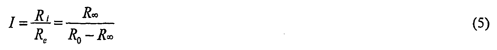
- Additionally, the total body water can also be used as an indicator for hydration status. In this example, by positioning the electrodes as shown in
Figure 8 , this allows impedance measurements across the subject's entire body to be determined. This in turn allows the subject's total body water (TBW) to be derived given by:
- where: TBW = total body water
- ecf = volume of extracellular fluid
- icf = volume of intracellular fluid
- In this regard, the volumes of extracellular and intracellular fluid can be derived from the values R0. R∞ as these depend on the values of the extracellular and intracellular resistance, as discussed above.
- The analysis of the extracellular fluid volumes, the index I and/or the total body water may be achieved in a number of ways, but typically involves comparing the parameters to available references, and accordingly, the process determines if references are available at
step 510. If references are available, the measuringdevice 1 allows the user to select an appropriate reference atstep 520. - For example, the reference can be in the form of earlier data collected for the respective subject, thereby allowing a longitudinal analysis to be performed. This typically requires that data are collected prior to dialysis or other interventions, allowing the measuring
device 1 to determine if there are any variations in the subject's extracellular fluid levels during the dialysis process, thereby indicating a change in subject hydration status. This can be performed for each body segment separately, or for the entire body. - However, the system may also or alternatively use a normal population database table, which includes reference values obtained from different subjects. This database table is essentially a single subject database table into which all measurements of normal population subjects (people without vascular insufficiency) are added.
- An example of such normal population data displayed using the
GUI 1000 is shown inFigure 7A . This table then acts as a pool of data from which normalised values for raw impedance data and ratios of impedance data can be generated, allowing comparison with measured values for the subject to be performed. - This generation of this normalised data is in the form of mean (averaged) values that are selected to be relevant to the test subject. The selection is performed based on the subject information and may be performed on the basis of any one of a number of factors, such as age, sex, height, weight, race, interventions, or the like.
- Therefore if the test subject is female then the normalised data drawn from the normal population database will be calculated from measurements from female subjects that are present in the in the normal population database.
- Thus, in one example, the operator is presented with the
GUI 1040 similar to that shown inFigure 7A , which allows the operator to select appropriate records from the normal population table, as shown by the highlighted entry at 1041. - It will be appreciated that the normalised population references are generally less accurate than subject specific references as these do not necessarily accurately model the subject's fluid levels and hence hydration status prior to undergoing dialysis.
- In the case of using a subject specific reference, this is generally achieved by ensuring measurements taken prior to surgery, requiring dialysis, interventions, heart disease, or other events that will have an impact on the hydration status. Thus, for example, if the subject is undergoing dialysis, then the reference can be formed from parameter values derived prior to commencement of the dialysis procedure.
- A common example is baseline measurements taken before surgical intervention for breast cancer that can be used to track subjects fluid shifts post surgery by comparison of study measurements to these baseline generated mean values.
- Subject specific baselines can be generated automatically from measurements in the subject's database table. This can in turn be used to provide cut off points for dialysis based on when the measured impedance values or derived indicators approach predetermined impedance or indicator values representing an ideal or optimal fluid level or hydration status.
- Generation of baselines can be achieved using the
GUI 1000 shown inFigure 7B , in which the subject's record is displayed. Located on theGUI 1000 are twoselection windows 1042, 1043 that are used to define the measurements used from the subject's database table to generate mean data values for comparison to study measurements. - It will be appreciated that the process can also be used to add data to the normal population table. This is achieved by performing the measurement process outlined above, and in the event that the subject is healthy, or the subject is a control, such as a family member, importing the data into the normal population table. This can be performed in addition to adding the measurements to the subject record, so that measurements collected from a healthy individual can be used for subsequent longitudinal analysis and/or as a normal population reference.
- In any event, once an appropriate reference is selected at
step 520, the measuringdevice 1 compares the currently determined indicator to the reference atstep 530, and utilises this to generate an indication of the hydrations status which is then displayed atstep 540. - If no reference is available, the indicators determined for each body segment are compared to the indicators determined for other ones of the body segments. This allows a relative distribution of fluid within the subject to be monitored, which in turn allows an indication of hydration status to be determined.
- For example, this can be used to determine the presence or absence of oedema. In the event that it is believed that the subject has one or more limbs at risk of oedema (i.e. suffering from vascular insufficiency of that limb), then the onset of oedema is in turn indicative of variations in the subject's hydration status. In this instance, the analysis of each of the limbs will be influenced by whether the subject is deemed to be at risk of bilateral oedema (i.e. suffering from vascular insufficiency of two limbs).
- In particular, if there is no risk of bilateral oedema, then the
processing system 10 can compare parameters for contra-lateral limbs. This may be achieved for example by determining an index based on a ratio of the extra- to intra- cellular fluid levels in each leg, and then comparing the values determined to assess whether there is difference between the limbs, or against a reference value for that limb, and hence whether there is a likelihood of oedema being present. - In the event that there is a likelihood of the vascular insufficiency being bilateral, then the
processing system 10 typically determines the index for each limb. A ratio of the determined index I for different pairs of limbs are then compared, thereby allowing the operator to determine if there is a likelihood of bilateral oedema. - In any event, it can be seen that if there is a major variation in the extracellular fluid volume, or the index I, either over time in the case of longitudinal analysis (either extending through a dialysis session, or extending over multiple sessions), compared to normal references, or between different body segments, this is indicative of a changing hydration status. This is in turn indicative of the fact that the dialysis procedure needs to be modified in order to counteract this change, and ensure that the subject is correctly hydrated.
- Accordingly, the measuring
device 1 can use this to display a report that is indicative of the hydration status, and/or the presence, absence or degree of oedema. - However, as an alternative to the above described process, the hydration status can be monitored by examining other indicators, such as by examining the impedances values at different selected frequencies.
- Thus, for example, this may involve calculating impedance values at specific frequencies in the complex impedance plot. This may include theoretical impedance values such as R0 and R∞, vectors representing the actual measured values, or theoretical values derived at set frequencies, as well as the difference between values of R0 and R∞.
- In one example, the process set out in
steps 510 to 540 can involve repeatedly making measurements during the dialysis procedure, and then monitoring the variation in one or more of the above mentioned indicators, such as the value of R∞, the level of extra-cellular fluid, the index I, or the like. - In this example, as dialysis proceeds, fluid levels within the subject's body should alter, resulting in a corresponding alteration of the indicator. As the dialysis procedure reaches a desired end point and fluid levels within the subject approach an ideal or optimal level, this will also result in a corresponding stabilisation of the indicators. Accordingly, in one example, the process involves monitoring for variation, and in particular, a rate of change of the indicators. When the rate of indicator variation falls below a predetermined threshold, this indicates that the value of the indicator, and hence patient fluid levels, have substantially stabilised, thereby allowing the dialysis procedure to be halted.
- Thus, in one example, the process involves monitoring changes in the values of indicators such as R0, R∞, the difference between R0 and R∞, vector impedance values, or any other indicator, and then using the rate of variation to control the dialysis process.
- Examples of the different types of available reports will now be described with reference to
Figures 7C to 7I . - As shown in
Figure 7C , the report is presented using aGUI 1050 that includes subject details shown generally at 1051. The GUI includescontrols 1052 that allow the operator to select whether reference data is to be used and the nature of the reference data. Thus, it will be appreciated that if a user varies the reference data selection, the process will return to step 540 to reassess the nature of the output dependent on the type of reference selected. At 1053A a drop down list is provided to indicate the nature of the parameter that is to be displayed, and at 1053B checkboxes are provided indicating the limbs for which the parameter is to be displayed. In addition to this, a limb of interest and a reference limb can be selected using thecheck boxes - The parameters available for charting include:
- Weight;
- Fluid loading;
- Ratio of indices;
- Ratio of body segment R0 values;
- The index for each individual body segment R0 for a body segment;
- R∞ for a body segment;
- The intracellular fluid resistance Ri;
- The characteristic frequency of the subject fc ;
- Standard error of estimates;
- Td time delay for each measurement; and,
- Values of a and τ from the Cole Model.
- Each of the parameters will now be described in more detail.
- The impedance vector plot is a graphical representation of when a subject's measurements move relative to a reference ellipse. The reference ellipse can be generated from a 95% confidence interval based on the subject specific baseline data or the normal population data.
- When data points of a study body segment are outside the ellipse, this indicates the presence of too much fluid in the corresponding body segment. The ellipse can be generated for and displayed for each body segment chosen using the reference limb checkbox. The data points displayed are those generated from the study body segment data for the subject. The study body segments and reference body segments are chosen using the body segment selector check boxes located underneath the chart.
-
Figure 7C shows an example of a fluid loading plot in which the index for left and right legs is compared. In this example, the index remains within the ellipse shown generally at 1056 highlighting that oedema is not present, and optimum dry mass has been obtained. However, when the right arm and left arm are compared as shown inFigure 7D , the values for the ratio comparisons fall outside the reference ellipse 1056 indicating that the right arm is suffering from fluid overload and may have vascular insufficiency. - In these examples, the fluid loading plot includes a comparison between limbs, and accordingly, the
checkboxes 1053B are not used. - An alternative example is shown in
Figure 7I . In this example, the reference ellipse is replaced byreference lines reference region 1070. In this example, the reference region may again be based on a 95% confidence interval from the subject's specific baseline data or the normal population data. - In contrast to the reference ellipse of
Figures 7C and 7D above, thereference region 1070 is generally more able to take into account variations in physical characteristics between subjects. For example, when a reference ellipse is determined based on population samples, then if a subject has particularly thin limbs, or short fat limbs, then the subject's measured value may fall outside the ellipse, even when the hydration status is normal. However, this does not occur with thereference region 1070. - A further benefit is that if the subject has some form of oedema and is over hydrated, then this will result in the measured index value that is positioned below the
reference line 1072, as shown for example at 1073. - If the measured index is determined to be above the
line 1071, as shown for example at 1074, this generally indicates either that the patient is dehydrated, which will require further clinical intervention, or investigation. Alternatively, this indicates that the electrodes have been incorrectly attached to the subject, in which case re-measurement may be required. - This will display the index I for a selected reference limb divided by the index I of the limb of interest.
-
Figure 7E is an example of the ratio of limb ratios in which a ratio of the index for the right arm and right legs is plotted against time. In this instance, it can be seen that a significant variation is present at 1057 indicating an undesirable fluid loading. - In this examples, as two limbs are again compared, the
checkboxes 1053B are not used, and are ignored. - This function will display the ratio of the R 0 of the reference body segment divided by that of a study body segment for each measurement in the subject's database table.
- The index I can also be displayed for each body segment for all measurements in the subjects database table as a chart over time, as shown in
Figure 7F . The body segments represented on the chart are selected using the control 1053. In this instance, as reference and study limbs are not defined, the 1054, 1055 are omitted for clarity. - The value of R0 can also displayed for each body segment for all measurements in the subjects database table as a chart over time.
- The value of R ∞ can also displayed for each body segment for all measurements in the subjects database table as a chart over time.
- The value of Ri can also displayed for each body segment for all measurements in the subjects database table as a chart over time.
- The characteristic frequency can also displayed for each body segment for all measurements in the subjects database table as a chart over time.
- The value of α and τ can also displayed for each body segment for all measurements in the subject's database table as a chart over time.
- The value of the standard estimate of errors (SEE) can also displayed for each body segment for all measurements in the subjects database table as a chart over time.
- The value of the time delay (Td) associated with each measurement can also displayed for each body segment for all measurements in the subjects database table as a chart over time.
- In each of the above outlined reports, reference values can also be displayed based either on the normalised population reference or subject specific reference.
- An example of the use of a subject's specific reference value is shown in
Figure 7F . In this instance the reference value is based on R0 as shown at 1058. Accordingly, it can be seen that variation of the value R0 compared to the reference is indicative of oedema. The generation of a report by comparison to normal population data will be performed in a similar manner. - In addition to simply displaying the absolute reference value determined, it is also possible to display standard deviations as shown at 1059 to thereby provide an indication of the degree of variation from the base line.
- A further feature of the process is the ability to associate event markers with specific measurements in the measurement database table. Event markers can provide commented time points that correspond to measurements and points in time. These can be customised by the user to indicate important events that need to be documented on the longitudinal analysis charts. Such events may include, onset date of oedema, the start of medical intervention, the beginning and end of dialysis sessions etc. These markers will be displayed automatically on the longitudinal charts that are a function over time. Event markers can also be shown on charts as shown for example in
Figure 7H . - In the above examples, the
processing system 10 therefore selects the types of analysis or representation that is most appropriate for determining the presence or absence of oedema based on the currently available data. This therefore removes the requirement for the operator to make an assessment of which form of report would provide the most accurate indication of the onset of oedema. - In the above example, the impedance measurements are collected for each of the limbs, with the assessment of the preferred type of analysis being performed after the measurements have been performed. However, as an alternative to this, the
processing system 10 can be adapted to determine the preferred type of analysis first and then only perform the measurements required in order for the type of analysis to be performed. - Thus a limited limb analysis can be performed, in which the operator specifies the limbs for which measurements are to be made prior to the measurement process. In this instance, data will only be collected for the limbs of interest.
- In addition to performing the measurements described above, it is possible that profiles can be configured to allow a range of different measurements to be performed.
- For example, the TBW can be used in:
- body composition analysis
- derivation of Fat Free Mass (FFM), which can in turn be used as an index of left ventricular mass;
- monitoring the build up of fluid in the body of cardiac patients, which can be used as an indicator of right ventricular failure.
- Furthermore, by subtracting measured impedance values obtained for each limb from the corresponding impedance values obtained for the entire body, this can be used to derive effective thoracic cavity impedance values. These values can in turn be used as indicators for pulmonary oedema, and hence left ventricular failure, as well as determining cardiac output.
- Thus, it will be appreciated that in addition to measuring hydration status, different measurement profiles can be determined to allow measurement of:
- Cardiac parameters;
- Pulmonary oedema;
- Lymphoedema;
- Body composition; and,
- Total body water.
- The above examples have been described on the basis of the selection of the preferred impedance measurements and analysis being performed by a
processing system 10 provided as part of the measuring device. However, this is not essential and that any or all of the functionality described could be performed by a processing system that is remotely located to the measuring device, as will now be described with respect toFigure 9 . - In this example, the measuring device 1 (which is shown as a single channel device for clarity purposes only) is connected to a
computer system 3, via theexternal interface 23 as shown. Thecomputer system 3 may be any form of computer system but is typically a desktop, laptop, tablet, PDA, Smart Phone or the like. - In this example, the
computer system 3 operates to control the measuringdevice 1 to perform the measurement procedure. The measuringdevice 1 therefore operates to generate required excitation signals, apply these to the subject, and measure the resulting voltages generated across the subject. Once impedance measurements have been collected, these are transferred via theexternal interface 23 to theend station 3, which operates to analyse the measured impedance values and generate the appropriate GUIs shown inFigures 5 to 8 . - In order to achieve this, the
computer system 3 may be connected to themeasuring device 1 via a wired, or wireless connection, or alternatively via anappropriate communications network 5, such as an Ethernet, LAN, WAN, the Internet, or the like. - In this instance, the operator of the system is generally required to place the measuring
device 1 in a predetermined operating mode allowing thecomputer system 3 to generate any required control signals to activate the measurement process. - In this example, communication between the
computer system 3 and the measuringdevice 1 is typically controlled using theGUI 1060 shown inFigure 10 . - The GUI includes
fields 1061 for defining IP connection details, which allows thecomputer system 3 to connect to the measuring device, via theexternal interface 23, via a TCP/IP or other network.Fields 1062 are used for defining paths via which the references can be obtained, with thefields 1063 defining details of the database from which the references should be obtained. -
Fields - It will therefore be appreciated from this that GUI can also be used to provide connections to remote databases, such as HL7 compliant subject databases. Furthermore, the architecture can be implemented in any one of a number of manners depending on the circumstances in which the
measuring device 1 is to be used. - Thus, for example, as a further alternative, the selection and/or analysis of the impedance measurements can be performed by a central base station coupled to a number of measuring devices via a suitable communications system, such as a computer network or the like. In this instance, once the base station has selected an impedance measurement type to be performed, the base station transfers an indication of this to the respective monitoring thereby causing the measuring device to display the necessary electrode connections. Once the impedance measurements have been performed, the determined measurements are returned to the base station for analysis.
- It will be appreciated that the location of fluid within a subject will vary significantly as the subject moves, and in particular as the subject changes their orientation or posture.
- For example, in performing dialysis it is typical for the subject to be seated in a relined position, in which case fluid is typically distributed unevenly throughout the body (and subject to any specific oedema or the like). If the subject were to stand up or lay down during the process, this results in a significant flow of fluid into or from the lower regions of the subject, such as the calf. Consequently, if measurements are made from the calf, there can be a significant variations in measured impedances associated with the subject's position.
- To take this into account, the measuring
device 1 may include an orientation sensor connected to themeasuring device 1 as aperipheral device 4, for example. In this instance, the orientation sensor is used to derive information regarding the subject's current orientation, and this could therefore take on any one of a number of forms. - Thus, for example, the orientation sensor could be provided in a subject's bed and operate to determine the subject's orientation based on the bed configuration. Alternatively, the orientation sensor may be coupled to the subject, and in particular to the subject's leg or calf, to determine the leg or calf orientation. It will be appreciated from this that any suitable sensor may be used, and in one example, the sensor is at least partially incorporated into the
electrodes 15. - In use, the measuring
device 1 can modify the impedance measurement analysis based on the orientation of the subject as determined from the orientation sensor. This can again be achieved in a number of manners. - For example, if the measuring
device 1 is comparing a current indication to a previous indication, such as by monitoring variations in the index I over time, the measuringdevice 1 can be adapted to ensure that indications are only compared to each other if made at the same subject orientation. Thus, if a preliminary impedance measurement prior to dialysis is used to establish a baseline reading, with subsequent measurements being compared thereto, the process may involve taking a baseline reading at each of a number of different orientations. In this instance, the measured readings would then be compared to the corresponding baseline determined for the same subject orientation. The fluid levels will also depend on the length of time a subject has been in a given orientation, and again this may be taken into account, for example, by ensuring comparison is made to prior readings in which the subject has maintained a similar posture for a similar amount of time. - Alternatively, by measuring different impedance values obtained over a range of orientations, this can be used to determine a correction factor, required to correct for certain orientations. This allows normalisation of any measured values to a specific orientation, allowing the above described analysis to be performed.
- A further variation is to examine differences in indicators between different subject orientations. In this instance, it will be appreciated that if the subject's hydration status is such that the subject has reached an ideal or optimal fluid level, and no further dialysis is required, then changes in orientation will have a reduced effect simply because there is less fluid within the body to be displaced.
- Accordingly, in a further example, the process involves determining a number of indicators at different subject orientations. The measuring
device 1 then compares the measured indications at each orientation and determines if the difference falls below a threshold. If so, then this indicates that there is minimal variations in fluid between the orientations, and hence that the hydration status is suitable to terminate the dialysis procedure. - Impedances values measured for a subject include a contribution from the subject's skin, known as a skin impedance. The skin impedance is heavily influenced by the hydration levels in the skin, which is in turn dependent on skin temperature.
- Accordingly, in a further example, the measuring
device 1 can use the skin temperature of the subject when analysing impedance values. This can be achieved in a number of ways. - For example, the skin temperature can be measured using a suitable thermometer, with the skin temperature being supplied to the
measuring device 1, via the I/O device 22. Alternatively, a skin temperature sensor can be provided as part of the measuring device, either as aperipheral device 4, or through incorporation into suitable electrodes, allowing the measuringdevice 1 to determine the subject's skin temperature automatically. - In this example, the skin temperature is generally used to generate a calibration factor, which is used to modify the measured impedance values, or subsequently determined indicators, depending on the skin temperature. The calibration factor is typically predetermined by analysis of a suitable sample population, across a variety of skin temperatures.
- An effect of the calibration factor is that it can be used to take into account subject ethnicity. In particular, it is generally accepted that different reference baselines must be used for subjects having different ethnicities, due to variations in skin impedance. However, by providing a correction factor taking into account both ethnicity and skin temperature, allows common baselines to be used by a wider range of subjects having a wider range of ethnicities.
- It will be appreciated that the above described electrode arrangements are only one of a number of possible electrode arrangements. For example, whilst the electrodes may be provided as discrete pads, alternatively a number of electrodes may be provided on a common substrate, for example in the case of band electrodes.
- Additionally, or alternatively, the electrodes may form part of another related device. For example, the voltage measuring electrodes positioned on either the calf or bicep can be incorporated into blood pressure cuff, to allow simultaneous measurement of blood pressure and impedance.
- In any event, it will be appreciated that the above described process provides an easy to use and non-invasive estimate of body composition parameters and fluid volumes. Segmental analysis provides a better estimate of these parameters then traditional whole body estimates. However the placement of electrodes in reproducible anatomic sites in the obese and the critically ill population is often impossible. By using the theory of equipotentials and sophisticated multiplexing it is possible to provide a robust bioimpedance platform capable of multiple measurement parameters for the dialysis patient.
- Persons skilled in the art will appreciate that numerous variations and modifications will become apparent. All such variations and modifications which become apparent to persons skilled in the art, should be considered to fall within the spirit and scope that the invention broadly appearing before described.
- Thus, for example, it will be appreciated that features from different examples above may be used interchangeably where appropriate. Furthermore, whilst the above examples have focussed on a subject such as a human, it will be appreciated that the measuring device and techniques described above can be used with any animal, including but not limited to, primates, livestock, performance animals, such race horses, or the like.
- It will also be appreciated above described techniques, may be implemented using devices that do not utilise the separate
first processing system 10 andsecond processing system 17, but rather can use a common single processing system, or use some other internal configuration.
Claims (14)
- Apparatus for determining an indication of the hydration status relating to a subject, the apparatus including a processing system (10) for:a) determining a measured impendance value for at least one body segment;b) for each body segment, and using the measured impedance values, determining at least one indicator, the indicator being at least partially indicative of a level of extracellular fluid;c) determining an indication of the hydration status using at least one determined indicator, characterised in that the processing system (10) is for:i) determining a subject orientation; andii) determining the hydration status using the orientation.
- Apparatus according to claim 1, wherein the apparatus includes:a) a current supply (11) for generating an alternating current at each of a plurality of frequencies;b) at least two supply electrodes (13A, 13B, 13C, 13D) for applying the generated alternating current to a subject;c) at least two measurement electrodes (15A, 15B, 15C, 15D) for detecting a voltage across the subject; and,d) a sensor (12) coupled to the measurement electrodes for determining the voltage, the sensor being coupled to the processing system to thereby allow the processing system (10) to determine the measured impedances.
- A method of determining an indication of the hydration status relating to a subject, the method including, in a processing system (10):a) determining a measured impedance value for at least one body segment;b) for each body segment, and using the measured impedance values, determining at least one indicator, the indicator being at least partially indicative of a level of extracellular fluid;c) determining an indication of the hydration status using at least one determined indicator, characterised in that the method includes:d) determining a subject orientation; ande) determining the hydration status using the orientation.
- A method according to claim 3, wherein the method includes, in the processing system (10):a) comparing the at least one indicator to at least one of:i) a predetermined reference;ii) an indicator determined for at least one other body segment; and,iii) a previously determined indicator; andb) determining an indication of the hydration status using the results of the comparison.
- A method according to claim 3 or 4, wherein the indicator is at least one of:a) an index (I) of the ratio of extra- to intra-cellular fluid; andb) an extracellular fluid volume.
- A method according to any one of the claims 3 to 5, wherein the method includes, in the processing system (10):a) determining a plurality of measured impedance values for each body segment, each measured impedance value being measured at a corresponding measurement frequency; andb) determining impedance parameter values based on the plurality of measured impedance values, the indicator being at least partially based on the determined impedance parameter values.
- A method according to claim 6, wherein the parameter values include R0 and R∞ , wherein:R0 is the resistance at zero frequency; andR∞ is the resistance at infinite frequency.
- A method according to claim 7, wherein the method includes:a) monitoring changes over time for at least one of:i) R0;ii) R∞;iii) a difference between R0 and R∞; andb) a vector indication of an impedance measurement.
- A method according to claim 6, wherein the method includes, in the processing system, determining the parameter values using the equation:

where:Z is the measured impendance at angular frequency ω,τ is a time constant, andα has a value between 0 and 1. - A method according to claim 9, wherein the method includes, in the processing system (10):a) determining the impedance of each body segment at four discrete frequencies; andb) determining values for the parameters by solving the equation using four simultaneous equations.
- A method according to any one of claims 3 to 10, wherein the indicator for a body segment is the extracellular fluid volume determined using the equation:

WhereECV = Extracellular fluid volumeCSegment = Geometry Constant which is 1 for an arm or leg and 4 for the thoracic cavityLSegment = Length of the segment in cmRSegment = Resistance of the segment in OhmρSegment = Resistivity coefficient which is nominally 47 Ohm/ cm - A method according to any one of claims 3 to 11, wherein the method includes, in the processing system (10):a) determining a correction factor; andb) determining the hydration status using the correction factor.
- A method according to any one of claims 3 to 12, wherein the method includes, in the processing system (10):a) determining a first indicator at a first subject orientation;b) determining a second indicator at a second subject orientation; andc) determining the hydration status using the difference between the first and second indicators.
- A method according to any one of claims 3 to 13, wherein the method includes, in the processing system (10):a) causing one or more electrical signals to be applied to the subject using a first set of electrodes (13A, 13B, 13C, 13D), the one or more electrical signals having a plurality of frequencies;b) determining an indication of electrical signals measured across a second set of electrodes (15A, 15B, 15C, 15D) applied to the subject in response to the applied one or more signals;c) determining from the indication and the one or more applied signals, an instantaneous impedance value at each of the plurality of frequencies; andc) determining the indicator using the instantaneous impedance values.
Applications Claiming Priority (2)
| Application Number | Priority Date | Filing Date | Title |
|---|---|---|---|
| AU2005905603A AU2005905603A0 (en) | 2005-10-11 | Hydration status monitoring | |
| PCT/AU2006/001491 WO2007041783A1 (en) | 2005-10-11 | 2006-10-10 | Hydration status monitoring |
Publications (3)
| Publication Number | Publication Date |
|---|---|
| EP1948017A1 EP1948017A1 (en) | 2008-07-30 |
| EP1948017A4 EP1948017A4 (en) | 2011-09-21 |
| EP1948017B1 true EP1948017B1 (en) | 2014-04-02 |
Family
ID=37942219
Family Applications (1)
| Application Number | Title | Priority Date | Filing Date |
|---|---|---|---|
| EP06790361.7A Active EP1948017B1 (en) | 2005-10-11 | 2006-10-10 | Hydration status monitoring |
Country Status (6)
| Country | Link |
|---|---|
| US (2) | US9724012B2 (en) |
| EP (1) | EP1948017B1 (en) |
| JP (1) | JP5208749B2 (en) |
| CA (1) | CA2625631C (en) |
| ES (1) | ES2476999T3 (en) |
| WO (1) | WO2007041783A1 (en) |
Cited By (6)
| Publication number | Priority date | Publication date | Assignee | Title |
|---|---|---|---|---|
| US8836345B2 (en) | 2007-11-05 | 2014-09-16 | Impedimed Limited | Impedance determination |
| US9149235B2 (en) | 2004-06-18 | 2015-10-06 | Impedimed Limited | Oedema detection |
| US9392947B2 (en) | 2008-02-15 | 2016-07-19 | Impedimed Limited | Blood flow assessment of venous insufficiency |
| US9585593B2 (en) | 2009-11-18 | 2017-03-07 | Chung Shing Fan | Signal distribution for patient-electrode measurements |
| US10004408B2 (en) | 2014-12-03 | 2018-06-26 | Rethink Medical, Inc. | Methods and systems for detecting physiology for monitoring cardiac health |
| GB2596983A (en) * | 2017-02-03 | 2022-01-12 | Bruin Biometrics Llc | Measurement of edema |
Families Citing this family (85)
| Publication number | Priority date | Publication date | Assignee | Title |
|---|---|---|---|---|
| AUPQ113799A0 (en) | 1999-06-22 | 1999-07-15 | University Of Queensland, The | A method and device for measuring lymphoedema |
| US7153829B2 (en) | 2002-06-07 | 2006-12-26 | Dyax Corp. | Kallikrein-inhibitor therapies |
| US8068906B2 (en) | 2004-06-21 | 2011-11-29 | Aorora Technologies Pty Ltd | Cardiac monitoring system |
| WO2006056074A1 (en) | 2004-11-26 | 2006-06-01 | Z-Tech (Canada) Inc. | Weighted gradient method and system for diagnosing disease |
| AU2006265763B2 (en) * | 2005-07-01 | 2012-08-09 | Impedimed Limited | Monitoring system |
| EP3287073A1 (en) * | 2005-07-01 | 2018-02-28 | Impedimed Limited | Monitoring system |
| EP1912563B1 (en) | 2005-08-02 | 2016-04-20 | Impedimed Limited | Impedance parameter values |
| JP5208749B2 (en) | 2005-10-11 | 2013-06-12 | インペダイムド・リミテッド | Hydration status monitoring |
| US10537671B2 (en) | 2006-04-14 | 2020-01-21 | Deka Products Limited Partnership | Automated control mechanisms in a hemodialysis apparatus |
| AU2007266311B2 (en) | 2006-05-30 | 2014-01-30 | Impedimed Limited | Impedance measurements |
| JP5372768B2 (en) | 2006-11-30 | 2013-12-18 | インぺディメッド リミテッド | measuring device |
| ES2543967T3 (en) * | 2007-01-15 | 2015-08-26 | Impedimed Limited | Method for performing impedance measurements on a subject |
| US8409441B2 (en) | 2007-02-27 | 2013-04-02 | Deka Products Limited Partnership | Blood treatment systems and methods |
| US10463774B2 (en) | 2007-02-27 | 2019-11-05 | Deka Products Limited Partnership | Control systems and methods for blood or fluid handling medical devices |
| US8491184B2 (en) | 2007-02-27 | 2013-07-23 | Deka Products Limited Partnership | Sensor apparatus systems, devices and methods |
| KR101861192B1 (en) | 2007-02-27 | 2018-05-28 | 데카 프로덕츠 리미티드 파트너쉽 | Hemodialysis apparatus and methods |
| JP5101685B2 (en) | 2007-03-30 | 2012-12-19 | インぺディメッド リミテッド | Operation protection circuit for variably controlling the compensation level to reduce the load of resistive and capacitive signals |
| CA2684324C (en) | 2007-04-20 | 2017-05-30 | Impedimed Limited | Monitoring system and probe |
| EP2155058B1 (en) * | 2007-05-14 | 2015-09-16 | Impedimed Limited | Indicator |
| US8287724B2 (en) * | 2007-07-05 | 2012-10-16 | Baxter International Inc. | Dialysis fluid measurement systems using conductive contacts |
| US20110046505A1 (en) | 2007-08-09 | 2011-02-24 | Impedimed Limited | Impedance measurement process |
| US8897868B2 (en) | 2007-09-14 | 2014-11-25 | Medtronic, Inc. | Medical device automatic start-up upon contact to patient tissue |
| WO2009036333A1 (en) | 2007-09-14 | 2009-03-19 | Corventis, Inc. | Dynamic pairing of patients to data collection gateways |
| WO2009036306A1 (en) | 2007-09-14 | 2009-03-19 | Corventis, Inc. | Adherent cardiac monitor with advanced sensing capabilities |
| US20090076345A1 (en) | 2007-09-14 | 2009-03-19 | Corventis, Inc. | Adherent Device with Multiple Physiological Sensors |
| EP2194864B1 (en) * | 2007-09-14 | 2018-08-29 | Medtronic Monitoring, Inc. | System and methods for wireless body fluid monitoring |
| US8591430B2 (en) | 2007-09-14 | 2013-11-26 | Corventis, Inc. | Adherent device for respiratory monitoring |
| WO2009036256A1 (en) | 2007-09-14 | 2009-03-19 | Corventis, Inc. | Injectable physiological monitoring system |
| US9204449B2 (en) * | 2008-01-22 | 2015-12-01 | Alcatel Lucent | Method of assigning an idle state access terminal to a carrier in a multiple carrier wireless communication system based on load on control channel resources |
| US10195330B2 (en) | 2008-01-23 | 2019-02-05 | Deka Products Limited Partnership | Medical treatment system and methods using a plurality of fluid lines |
| US10201647B2 (en) | 2008-01-23 | 2019-02-12 | Deka Products Limited Partnership | Medical treatment system and methods using a plurality of fluid lines |
| AU2009214826B2 (en) * | 2008-02-15 | 2014-12-18 | Impedimed Limited | Analysing impedance measurements |
| ITPC20080030A1 (en) * | 2008-07-07 | 2010-01-08 | Giancarlo Mariani | APPARATUS FOR DETECTION, PROCESSING AND VISUALIZATION OF ELECTROPHYSIOLOGICAL DATA TO ENABLE THE EVALUATION OF THE CELLULAR BIOELECTRIC STATE AND THE BODY COMPOSITION SUBJECT TO INVESTIGATION |
| EP2350897B1 (en) * | 2008-08-27 | 2019-10-09 | Deka Products Limited Partnership | Control architecture and methods for blood treatment systems |
| GB0815752D0 (en) * | 2008-09-01 | 2008-10-08 | Maarek Albert | Medical device |
| US11857293B2 (en) | 2008-10-29 | 2024-01-02 | Flashback Technologies, Inc. | Rapid detection of bleeding before, during, and after fluid resuscitation |
| US11395634B2 (en) | 2008-10-29 | 2022-07-26 | Flashback Technologies, Inc. | Estimating physiological states based on changes in CRI |
| US11382571B2 (en) | 2008-10-29 | 2022-07-12 | Flashback Technologies, Inc. | Noninvasive predictive and/or estimative blood pressure monitoring |
| US11478190B2 (en) | 2008-10-29 | 2022-10-25 | Flashback Technologies, Inc. | Noninvasive hydration monitoring |
| US9757041B2 (en) | 2008-10-29 | 2017-09-12 | Flashback Technologies, Inc. | Hemodynamic reserve monitor and hemodialysis control |
| US11395594B2 (en) | 2008-10-29 | 2022-07-26 | Flashback Technologies, Inc. | Noninvasive monitoring for fluid resuscitation |
| US11406269B2 (en) | 2008-10-29 | 2022-08-09 | Flashback Technologies, Inc. | Rapid detection of bleeding following injury |
| US8512260B2 (en) | 2008-10-29 | 2013-08-20 | The Regents Of The University Of Colorado, A Body Corporate | Statistical, noninvasive measurement of intracranial pressure |
| US9615766B2 (en) | 2008-11-28 | 2017-04-11 | Impedimed Limited | Impedance measurement process |
| US8823490B2 (en) | 2008-12-15 | 2014-09-02 | Corventis, Inc. | Patient monitoring systems and methods |
| US20100234754A1 (en) * | 2009-03-11 | 2010-09-16 | Latman Neal S | Method and apparatus for measuring the state of hydration of hairy animals such as horses, camels, and the like |
| WO2011022068A1 (en) | 2009-08-21 | 2011-02-24 | Rutkove Seward B | A hand-held device for electrical impedance myography |
| EP2305112A1 (en) * | 2009-10-01 | 2011-04-06 | seca ag | Bioimpedance measuring device |
| US9538938B2 (en) | 2009-10-02 | 2017-01-10 | Koninklijke Philips N.V. | Signal transmission through a medium |
| US8790259B2 (en) | 2009-10-22 | 2014-07-29 | Corventis, Inc. | Method and apparatus for remote detection and monitoring of functional chronotropic incompetence |
| JP5643829B2 (en) | 2009-10-26 | 2014-12-17 | インぺディメッド リミテッドImpedimed Limited | Method and apparatus for use in impedance measurement analysis |
| US9451897B2 (en) | 2009-12-14 | 2016-09-27 | Medtronic Monitoring, Inc. | Body adherent patch with electronics for physiologic monitoring |
| WO2011075769A1 (en) * | 2009-12-21 | 2011-06-30 | Impedimed Limited | Analysing impedance measurements |
| US8965498B2 (en) | 2010-04-05 | 2015-02-24 | Corventis, Inc. | Method and apparatus for personalized physiologic parameters |
| US8380297B2 (en) * | 2010-05-17 | 2013-02-19 | John Collins | System for measuring a user's percentage of body fat |
| US20130172776A1 (en) | 2010-07-02 | 2013-07-04 | Impedimed Limited | Tissue indicator determination |
| DE102010031530A1 (en) | 2010-07-19 | 2012-01-19 | Fresenius Medical Care Deutschland Gmbh | Patient storage device, treatment device with a patient support device and corresponding method for controlling and / or regulating a medical treatment device |
| US9554725B2 (en) * | 2010-08-03 | 2017-01-31 | Medtronic Monitoring, Inc. | Medical device and methods of monitoring a patient with renal dysfunction |
| EP2469431B1 (en) * | 2010-12-23 | 2018-10-10 | Fresenius Medical Care Deutschland GmbH | A method for calculating or approximating a value representing the relative blood volume and devices |
| US9724458B2 (en) | 2011-05-24 | 2017-08-08 | Deka Products Limited Partnership | Hemodialysis system |
| DE102011053935B4 (en) * | 2011-09-26 | 2013-11-28 | Fresenius Medical Care Deutschland Gmbh | Method, device and system for blood treatment of a patient |
| US8700121B2 (en) | 2011-12-14 | 2014-04-15 | Intersection Medical, Inc. | Devices for determining the relative spatial change in subsurface resistivities across frequencies in tissue |
| ES2736950T3 (en) * | 2012-04-26 | 2020-01-09 | Fresenius Medical Care Deutschland Gmbh | Electrodes for a bioimpedance measuring device and devices used during dialysis |
| JP5953490B2 (en) * | 2012-05-10 | 2016-07-20 | 株式会社タニタ | Edema evaluation device |
| US9591987B1 (en) * | 2013-08-23 | 2017-03-14 | Rjl Systems, Inc. | Determining body composition through segmental bioelectrical impedance analysis (BIA) |
| CA2930702A1 (en) * | 2013-11-14 | 2015-05-21 | Flashback Technologies, Inc. | Noninvasive monitoring for fluid resuscitation |
| JP6813563B2 (en) * | 2015-07-16 | 2021-01-13 | インペディメッド・リミテッド | Determining fluid level |
| EP3416549A4 (en) * | 2016-02-16 | 2019-09-18 | Impedimed Limited | Heart failure indicator |
| JP2019523678A (en) * | 2016-06-06 | 2019-08-29 | トゥーセンス,インコーポレイテッド | Physiological monitoring device for monitoring patients undergoing hemodialysis |
| KR102035642B1 (en) | 2016-10-06 | 2019-10-23 | 주식회사 인바디 | Body composition mesurement using clamp electrode |
| TWI598073B (en) * | 2016-12-15 | 2017-09-11 | 財團法人工業技術研究院 | Physiological signal measuring method and physiological signal measuring device |
| DE102017105447A1 (en) * | 2017-03-14 | 2018-09-20 | senetics healthcare group GmbH & Co. KG | Apparatus and method for determining the hydration state of a human or mammalian body |
| AU2018286480B2 (en) * | 2017-06-14 | 2023-12-14 | Impedimed Limited | Indicator determination |
| AU2018300002B2 (en) * | 2017-07-11 | 2021-02-18 | Fresenius Medical Care Holdings, Inc. | Techniques for determining fluid volumes using bioimpedance information |
| WO2019188687A1 (en) * | 2018-03-29 | 2019-10-03 | テルモ株式会社 | Device, method, and program for measuring amount of body water |
| CN113316417A (en) * | 2018-12-21 | 2021-08-27 | 费森尤斯医疗保健控股公司 | Skin sodium measurement using bioimpedance |
| US11918386B2 (en) | 2018-12-26 | 2024-03-05 | Flashback Technologies, Inc. | Device-based maneuver and activity state-based physiologic status monitoring |
| JP7184341B2 (en) * | 2019-02-28 | 2022-12-06 | 学校法人常翔学園 | Needle removal detection method and extracorporeal blood circulation device using the method |
| JP7218660B2 (en) * | 2019-04-15 | 2023-02-07 | ニプロ株式会社 | Extracellular fluid volume standardization device, extracellular fluid volume evaluation device provided with the same, and computer program for standardizing extracellular fluid volume |
| EP4025116A4 (en) * | 2019-05-24 | 2024-03-06 | Convatec Technologies Inc | Portable dehydration monitoring system |
| CN110236542B (en) * | 2019-06-25 | 2023-04-18 | 歌尔科技有限公司 | Human body moisture state prompting method and device and mouse |
| US11701022B2 (en) * | 2020-01-06 | 2023-07-18 | Fresenius Medical Care Deutschland Gmbh | Method for calibrating a bioimpedance measuring device, and medical devices |
| WO2022070108A1 (en) * | 2020-09-30 | 2022-04-07 | Inomedis Inc. | Patch for monitoring heart signals and portable vital parameters monitoring device comprising same |
| ES2940732A1 (en) * | 2021-11-08 | 2023-05-10 | Servicio Andaluz De Salud | Device, system and procedure for monitoring a patient with heart failure (Machine-translation by Google Translate, not legally binding) |
| EP4299001A1 (en) * | 2022-06-27 | 2024-01-03 | Universidad de Jaén | Wearable device, system, and method for monitoring homeostatic state |
Family Cites Families (519)
| Publication number | Priority date | Publication date | Assignee | Title |
|---|---|---|---|---|
| GB213558A (en) | 1923-03-26 | 1924-07-17 | Edgar Von Bleichroeder | Collapsible coat hanger |
| FR1344459A (en) * | 1962-10-18 | 1963-11-29 | Method and apparatus for the electrical study of living organisms | |
| USRE30101E (en) * | 1964-08-19 | 1979-09-25 | Regents Of The University Of Minnesota | Impedance plethysmograph |
| US4314563A (en) | 1970-09-24 | 1982-02-09 | The United States Of America As Represented By The Administrator Of The Veterans Administration | Apparatus for measuring relative changes in blood volume in a portion of an animal body to detect a venous occlusion |
| US3834374A (en) | 1972-04-06 | 1974-09-10 | M Ensanian | Diagnostic electrical scanning |
| DE2316326A1 (en) | 1972-05-08 | 1973-11-29 | Siepem Fa | COMBINED DEVICE FOR HAIR HYGIENE AND FACIAL CARE |
| US3871359A (en) | 1973-06-25 | 1975-03-18 | Interscience Technology Corp | Impedance measuring system |
| US3851641A (en) | 1973-11-29 | 1974-12-03 | J Toole | Method and apparatus for determining internal impedance of animal body part |
| US3996924A (en) | 1974-06-19 | 1976-12-14 | Wheeler H Brownell | Occlusive impedance phlebograph and method therefor |
| US4008712A (en) | 1975-11-14 | 1977-02-22 | J. M. Richards Laboratories | Method for monitoring body characteristics |
| FR2354744A1 (en) | 1976-06-16 | 1978-01-13 | Commissariat Energie Atomique | OCCLUSION RHEOPLETHYSMOGRAPHY DEVICE |
| US4034854A (en) | 1976-07-16 | 1977-07-12 | M I Systems, Inc. | Electrode package |
| US4082087A (en) | 1977-02-07 | 1978-04-04 | Isis Medical Instruments | Body contact electrode structure for deriving electrical signals due to physiological activity |
| US4184486A (en) | 1977-08-11 | 1980-01-22 | Radelkis Elektrokemiai Muszergyarto Szovetkezet | Diagnostic method and sensor device for detecting lesions in body tissues |
| US4458694A (en) | 1977-11-02 | 1984-07-10 | Yeda Research & Development Co., Ltd. | Apparatus and method for detection of tumors in tissue |
| IL53286A (en) | 1977-11-02 | 1980-01-31 | Yeda Res & Dev | Apparatus and method for detection of tumors in tissue |
| DE2912349A1 (en) | 1979-03-29 | 1980-10-16 | Liebisch Geb | Detector system for human skin moisture content - has scanning head with two contact electrodes attached to skin under specified pressure |
| US4365634A (en) | 1979-12-06 | 1982-12-28 | C. R. Bard, Inc. | Medical electrode construction |
| US4353372A (en) | 1980-02-11 | 1982-10-12 | Bunker Ramo Corporation | Medical cable set and electrode therefor |
| FR2486386A1 (en) | 1980-07-09 | 1982-01-15 | Argamakoff Alexis | Thermographic and impedance measurer for cancer scanning - has single electrode or matrix supplying temp. and impedance signals |
| US4407300A (en) | 1980-07-14 | 1983-10-04 | Davis Robert E | Potentiometric diagnosis of cancer in vivo |
| JPS5772627A (en) | 1980-10-21 | 1982-05-07 | Tokyo Shibaura Electric Co | Apparatus for detecting abnormal cell |
| US4401356A (en) | 1980-11-24 | 1983-08-30 | C. R. Bard, Inc. | Electrical terminal |
| US4942880A (en) | 1981-01-28 | 1990-07-24 | Ceske Vysoke Uceni Technicke V Praze | Method for non-invasive electric diagnosis and therapy in hemodialysis and general medicine |
| US4407288B1 (en) | 1981-02-18 | 2000-09-19 | Mieczyslaw Mirowski | Implantable heart stimulator and stimulation method |
| IL62861A (en) | 1981-05-13 | 1988-01-31 | Yeda Res & Dev | Method and apparatus for carrying out electric tomography |
| CA1196691A (en) | 1982-01-12 | 1985-11-12 | Bradley Fry | Reconstruction system and methods for impedance imaging |
| SE455043B (en) | 1982-04-22 | 1988-06-20 | Karolinska Inst | DEVICE FOR MONITORING THE LIQUID BALANCE OF THE HUMAN BODY BY MEASURING THE IMPEDANCE OF THE BODY |
| US4617939A (en) | 1982-04-30 | 1986-10-21 | The University Of Sheffield | Tomography |
| US4450527A (en) * | 1982-06-29 | 1984-05-22 | Bomed Medical Mfg. Ltd. | Noninvasive continuous cardiac output monitor |
| GB2126732B (en) | 1982-09-02 | 1986-01-15 | British Telecomm | Impedance measurement in 4-wire to 2-wire converters |
| GB2131558B (en) | 1982-11-05 | 1986-03-05 | Walter Farrer | Measuring potential difference |
| SU1132911A1 (en) | 1983-02-18 | 1985-01-07 | Muzhikov Valerij G | Method of diagnosis of vascular insufficiency of lower extremities |
| US4557271A (en) | 1983-05-11 | 1985-12-10 | Stoller Kenneth P | Method and apparatus for detecting body illness, dysfunction, disease and/or pathology |
| FR2557318A1 (en) | 1983-12-26 | 1985-06-28 | A2F | ELECTRONIC DEVICE PROVIDING A UNIVERSAL INTERFACE BETWEEN SENSORS AND AN APPARATUS FOR INPUT AND SIGNAL PROCESSING FROM SUCH SENSORS |
| US4583549A (en) | 1984-05-30 | 1986-04-22 | Samir Manoli | ECG electrode pad |
| US4646754A (en) | 1985-02-19 | 1987-03-03 | Seale Joseph B | Non-invasive determination of mechanical characteristics in the body |
| US4688580A (en) | 1985-07-11 | 1987-08-25 | The Johns Hopkins University | Non-invasive electromagnetic technique for monitoring bone healing and bone fracture localization |
| US4686477A (en) | 1985-09-30 | 1987-08-11 | Mobil Oil Corporation | Multiple frequency electric excitation method and identifying complex lithologies of subsurface formations |
| US4763660A (en) | 1985-12-10 | 1988-08-16 | Cherne Industries, Inc. | Flexible and disposable electrode belt device |
| DE3775281D1 (en) | 1986-06-16 | 1992-01-30 | Siemens Ag | DEVICE FOR CONTROLLING A HEART PACER BY MEANS OF IMPEDANCE ON BODY TISSUES. |
| US4836214A (en) | 1986-12-01 | 1989-06-06 | Bomed Medical Manufacturing, Ltd. | Esophageal electrode array for electrical bioimpedance measurement |
| WO1988007392A1 (en) | 1987-03-26 | 1988-10-06 | Intrinsic Ag | Signal control process, electric treatment device and electrode system |
| US4832608A (en) | 1987-05-22 | 1989-05-23 | Cherne Medical, Inc. | Electrode belt adapter |
| CN1024161C (en) | 1987-09-05 | 1994-04-13 | 哈尔滨工业大学 | Intellectual faculties type free respiration resistant tachogram picturing instrument |
| US4911175A (en) | 1987-09-17 | 1990-03-27 | Diana Twyman | Method for measuring total body cell mass and total extracellular mass by bioelectrical resistance and reactance |
| US4924875A (en) * | 1987-10-09 | 1990-05-15 | Biometrak Corporation | Cardiac biopotential analysis system and method |
| JPH01288233A (en) | 1988-02-20 | 1989-11-20 | Hiroshi Motoyama | Bioinformation measuring instrument |
| US5184624A (en) | 1988-04-15 | 1993-02-09 | The University Of Sheffield | Electrical impedance tomography |
| US5078134A (en) | 1988-04-25 | 1992-01-07 | Lifecor, Inc. | Portable device for sensing cardiac function and automatically delivering electrical therapy |
| US4928690A (en) | 1988-04-25 | 1990-05-29 | Lifecor, Inc. | Portable device for sensing cardiac function and automatically delivering electrical therapy |
| US4895163A (en) | 1988-05-24 | 1990-01-23 | Bio Analogics, Inc. | System for body impedance data acquisition |
| US4951682A (en) | 1988-06-22 | 1990-08-28 | The Cleveland Clinic Foundation | Continuous cardiac output by impedance measurements in the heart |
| DE3821575A1 (en) | 1988-06-25 | 1989-12-28 | Philips Patentverwaltung | ARRANGEMENT FOR APPROXIMATELY DETERMINING THE REPLACEMENT CIRCUIT OF AN ELECTRICAL OR. ELECTRONIC COMPONENTS AT HIGH FREQUENCIES |
| US5020541A (en) | 1988-07-13 | 1991-06-04 | Physio-Control Corporation | Apparatus for sensing lead and transthoracic impedances |
| US4952928A (en) | 1988-08-29 | 1990-08-28 | B. I. Incorporated | Adaptable electronic monitoring and identification system |
| US4955383A (en) | 1988-12-22 | 1990-09-11 | Biofield Corporation | Discriminant function analysis method and apparatus for disease diagnosis and screening |
| DE3900696A1 (en) | 1989-01-12 | 1990-07-19 | Veba Oel Technologie Gmbh | MELTING PLANT FOR SOLID PRODUCTS FROM BARRELS |
| US4890630A (en) * | 1989-01-23 | 1990-01-02 | Cherne Medical, Inc. | Bio-electric noise cancellation system |
| US5511553A (en) | 1989-02-15 | 1996-04-30 | Segalowitz; Jacob | Device-system and method for monitoring multiple physiological parameters (MMPP) continuously and simultaneously |
| US4905705A (en) * | 1989-03-03 | 1990-03-06 | Research Triangle Institute | Impedance cardiometer |
| IL91193A (en) | 1989-08-02 | 1996-01-19 | Yeda Res & Dev | Tumor detection system |
| US5086781A (en) * | 1989-11-14 | 1992-02-11 | Bookspan Mark A | Bioelectric apparatus for monitoring body fluid compartments |
| GB9013177D0 (en) | 1990-06-13 | 1990-08-01 | Brown Brian H | Real-time imaging, etc. |
| JPH0496733A (en) | 1990-08-13 | 1992-03-30 | Nec San-Ei Instr Co Ltd | Living body impedance measuring device |
| US5063937A (en) | 1990-09-12 | 1991-11-12 | Wright State University | Multiple frequency bio-impedance measurement system |
| US5272624A (en) | 1990-10-02 | 1993-12-21 | Rensselaer Polytechnic Institute | Current patterns for impedance tomography |
| US5526808A (en) * | 1990-10-04 | 1996-06-18 | Microcor, Inc. | Method and apparatus for noninvasively determining hematocrit |
| SE466987B (en) | 1990-10-18 | 1992-05-11 | Stiftelsen Ct Foer Dentaltekni | DEVICE FOR DEEP-SELECTIVE NON-INVASIVE, LOCAL SEATING OF ELECTRICAL IMPEDANCE IN ORGANIC AND BIOLOGICAL MATERIALS AND PROBE FOR SEATING ELECTRICAL IMPEDANCE |
| US5199432A (en) | 1990-10-30 | 1993-04-06 | American Home Products Corporation | Fetal electrode product for use in monitoring fetal heart rate |
| EP0487776A1 (en) | 1990-11-29 | 1992-06-03 | Siemens Aktiengesellschaft | Method and apparatus for determining a parameter during the delivery of an electric pulse to a biological tissue |
| DE4100568A1 (en) | 1991-01-11 | 1992-07-16 | Fehling Guido | DEVICE FOR MONITORING A PATIENT FOR REPELLATION REACTIONS OF AN IMPLANTED ORGAN |
| US5101828A (en) * | 1991-04-11 | 1992-04-07 | Rutgers, The State University Of Nj | Methods and apparatus for nonivasive monitoring of dynamic cardiac performance |
| US5280429A (en) * | 1991-04-30 | 1994-01-18 | Xitron Technologies | Method and apparatus for displaying multi-frequency bio-impedance |
| US5197479A (en) | 1991-05-13 | 1993-03-30 | Mortara Instrument | Automatic electrode channel impedance measurement system for egg monitor |
| JPH05196681A (en) | 1991-06-26 | 1993-08-06 | Digital Equip Corp <Dec> | Method and apparatus for testing interconnection of continuously moving electric circuit |
| US5588429A (en) | 1991-07-09 | 1996-12-31 | Rensselaer Polytechnic Institute | Process for producing optimal current patterns for electrical impedance tomography |
| US5381333A (en) | 1991-07-23 | 1995-01-10 | Rensselaer Polytechnic Institute | Current patterns for electrical impedance tomography |
| US5544662A (en) | 1991-07-09 | 1996-08-13 | Rensselaer Polytechnic Institute | High-speed electric tomography |
| US5284142A (en) | 1991-12-16 | 1994-02-08 | Rensselaer Polytechnic Institute | Three-dimensional impedance imaging processes |
| US5390110A (en) | 1991-07-09 | 1995-02-14 | Rensselaer Polytechnic Institute | Layer stripping process for impedance imaging |
| US5208429A (en) | 1991-07-26 | 1993-05-04 | Carrier Corporation | Combination muffler and check valve for a screw compressor |
| GB9116215D0 (en) | 1991-07-26 | 1991-09-11 | Nat Res Dev | Electrical impedance tomography |
| US5423326A (en) * | 1991-09-12 | 1995-06-13 | Drexel University | Apparatus and method for measuring cardiac output |
| US5309917A (en) * | 1991-09-12 | 1994-05-10 | Drexel University | System and method of impedance cardiography and heartbeat determination |
| GB2260416B (en) | 1991-10-10 | 1995-07-26 | Smiths Industries Plc | Resistance monitors |
| DE4134960A1 (en) | 1991-10-23 | 1993-04-29 | Popp Fritz Albert Dr | METHOD FOR A HOLISTIC ANALYSIS OF THE HEALTH CONDITION |
| US5305192A (en) | 1991-11-01 | 1994-04-19 | Linear Technology Corporation | Switching regulator circuit using magnetic flux-sensing |
| US5415164A (en) | 1991-11-04 | 1995-05-16 | Biofield Corp. | Apparatus and method for screening and diagnosing trauma or disease in body tissues |
| US5906614A (en) | 1991-11-08 | 1999-05-25 | Ep Technologies, Inc. | Tissue heating and ablation systems and methods using predicted temperature for monitoring and control |
| US5415176A (en) | 1991-11-29 | 1995-05-16 | Tanita Corporation | Apparatus for measuring body fat |
| US5351697A (en) | 1991-12-16 | 1994-10-04 | Rensseleaer Polytechnic Institute | Three-dimensional impedance imaging process |
| US5282840A (en) | 1992-03-26 | 1994-02-01 | Medtronic, Inc. | Multiple frequency impedance measurement system |
| JPH06168A (en) | 1992-06-22 | 1994-01-11 | Hitachi Ltd | Method and device for measuring electric impedance distribution |
| US5735284A (en) * | 1992-06-24 | 1998-04-07 | N.I. Medical Ltd. | Method and system for non-invasive determination of the main cardiorespiratory parameters of the human body |
| IL102300A (en) | 1992-06-24 | 1996-07-23 | N I Medical Ltd | Non-invasive system for determining of the main cardiorespiratory parameters of the human body |
| US5372141A (en) | 1992-07-01 | 1994-12-13 | Body Composition Analyzers, Inc. | Body composition analyzer |
| US5231990A (en) | 1992-07-09 | 1993-08-03 | Spacelabs, Medical, Inc. | Application specific integrated circuit for physiological monitoring |
| GB9222888D0 (en) * | 1992-10-30 | 1992-12-16 | British Tech Group | Tomography |
| WO1994010922A1 (en) | 1992-11-13 | 1994-05-26 | Ep Technologies, Inc. | Cardial ablation systems using temperature monitoring |
| US5557210A (en) | 1992-11-20 | 1996-09-17 | Pacesetter, Inc. | Universal cable connector for temporarily connecting implantable stimulation leads and implantable stimulation devices with a non-implantable system analyzer |
| US5335667A (en) | 1992-11-20 | 1994-08-09 | University Of Utah Research Foundation | Method and apparatus for determining body composition using bioelectrical impedance |
| GB9226376D0 (en) * | 1992-12-18 | 1993-02-10 | British Tech Group | Tomography |
| DE4243628A1 (en) | 1992-12-22 | 1994-06-23 | Siemens Ag | Device for the non-invasive determination of the spatial distribution of the electrical impedance inside a living being |
| GB9312327D0 (en) | 1993-06-15 | 1993-07-28 | British Tech Group | Laser ultrasound probe and ablator |
| US5454377A (en) * | 1993-10-08 | 1995-10-03 | The Ohio State University | Method for measuring the myocardial electrical impedance spectrum |
| ZA948393B (en) | 1993-11-01 | 1995-06-26 | Polartechnics Ltd | Method and apparatus for tissue type recognition |
| JP2510401B2 (en) | 1994-01-10 | 1996-06-26 | 有限会社東洋医学 | Acupuncture device using high frequency |
| US5947910A (en) | 1994-01-14 | 1999-09-07 | E-Z-Em, Inc. | Extravasation detection technique |
| US5964703A (en) | 1994-01-14 | 1999-10-12 | E-Z-Em, Inc. | Extravasation detection electrode patch |
| WO1995024155A1 (en) | 1994-03-11 | 1995-09-14 | British Technology Group Limited | Electrical impedance tomography |
| RU2112416C1 (en) | 1994-05-10 | 1998-06-10 | Научно-исследовательский институт вычислительной техники | Method for checking of tissue or organ condition after operation and device for its realization |
| US5807270A (en) | 1994-06-20 | 1998-09-15 | Williams; Christopher Edward | Brain damage monitor |
| US5704355A (en) | 1994-07-01 | 1998-01-06 | Bridges; Jack E. | Non-invasive system for breast cancer detection |
| US5505209A (en) | 1994-07-07 | 1996-04-09 | Reining International, Ltd. | Impedance cardiograph apparatus and method |
| US6560480B1 (en) * | 1994-10-24 | 2003-05-06 | Transscan Medical Ltd. | Localization of anomalies in tissue and guidance of invasive tools based on impedance imaging |
| US5810742A (en) | 1994-10-24 | 1998-09-22 | Transcan Research & Development Co., Ltd. | Tissue characterization based on impedance images and on impedance measurements |
| NZ287251A (en) | 1994-10-24 | 1998-09-24 | Transscan Res & Dev Co Ltd | Multi electrode probe and method for impedance imaging of living biological tissue |
| US6678552B2 (en) | 1994-10-24 | 2004-01-13 | Transscan Medical Ltd. | Tissue characterization based on impedance images and on impedance measurements |
| US5615689A (en) | 1994-12-12 | 1997-04-01 | St. Luke's-Roosevelt Hospital | Method of predicting body cell mass using bioimpedance analysis |
| JPH08191808A (en) | 1995-01-13 | 1996-07-30 | Sekisui Chem Co Ltd | Living body electric impedance-measuring apparatus |
| US5562607A (en) | 1995-01-18 | 1996-10-08 | Alza Corporation | Electrotransport device having reusable controller power saver |
| US5503157A (en) * | 1995-03-17 | 1996-04-02 | Sramek; Bohumir | System for detection of electrical bioimpedance signals |
| DE19514698C1 (en) | 1995-04-13 | 1996-12-12 | Siemens Ag | Procedure for taking a distance measurement |
| US5557242A (en) | 1995-05-22 | 1996-09-17 | Motorola, Inc. | Method and apparatus for dielectric absorption compensation |
| US5575929A (en) | 1995-06-05 | 1996-11-19 | The Regents Of The University Of California | Method for making circular tubular channels with two silicon wafers |
| US5919142A (en) | 1995-06-22 | 1999-07-06 | Btg International Limited | Electrical impedance tomography method and apparatus |
| JP3492038B2 (en) | 1995-08-17 | 2004-02-03 | 積水化学工業株式会社 | Body fat measurement device |
| NL1001282C2 (en) | 1995-09-26 | 1997-03-28 | A J Van Liebergen Holding B V | Stroke volume determination device for a human heart. |
| US5813404A (en) | 1995-10-20 | 1998-09-29 | Aspect Medical Systems, Inc. | Electrode connector system |
| US5807272A (en) * | 1995-10-31 | 1998-09-15 | Worcester Polytechnic Institute | Impedance spectroscopy system for ischemia monitoring and detection |
| GB9524968D0 (en) | 1995-12-06 | 1996-02-07 | Brown Brian H | Impedance pneumography |
| US5827184A (en) | 1995-12-29 | 1998-10-27 | Minnesota Mining And Manufacturing Company | Self-packaging bioelectrodes |
| JPH09220209A (en) | 1996-02-20 | 1997-08-26 | Sekisui Chem Co Ltd | Living body electric impedance measuring instrument |
| US6790178B1 (en) * | 1999-09-24 | 2004-09-14 | Healthetech, Inc. | Physiological monitor and associated computation, display and communication unit |
| US5685316A (en) | 1996-04-08 | 1997-11-11 | Rheo-Graphic Pte Ltd. | Non-invasive monitoring of hemodynamic parameters using impedance cardiography |
| US6011992A (en) | 1996-05-09 | 2000-01-04 | Church Of Spirtual Technology | System for measuring and indicating changes in the resistance of a living body |
| AU3062597A (en) | 1996-05-10 | 1997-12-05 | Surviva-Link Corporation | Defibrillator electrode circuitry |
| FR2748928A1 (en) | 1996-05-23 | 1997-11-28 | Jabourian Artin Pascal | Portable electronic cardiac rhythm detector |
| JPH10185A (en) | 1996-06-17 | 1998-01-06 | Sekisui Chem Co Ltd | Diagnosing device for failure in body fluid |
| RU2138193C1 (en) | 1996-06-26 | 1999-09-27 | Государственное предприятие конструкторское бюро "СПЕЦВУЗАВТОМАТИКА" | Method of separation of electrical component of cardiac activity |
| CA2258081A1 (en) | 1996-06-26 | 1997-12-31 | University Of Utah Research Foundation | Method of broad band electromagnetic holographic imaging |
| JP3636826B2 (en) | 1996-07-01 | 2005-04-06 | 積水化学工業株式会社 | Bioelectrical impedance measuring device |
| JPH1014899A (en) | 1996-07-05 | 1998-01-20 | Sekisui Chem Co Ltd | Method and device for presumption of body composition |
| US5749369A (en) | 1996-08-09 | 1998-05-12 | R.S. Medical Monitoring Ltd. | Method and device for stable impedance plethysmography |
| US5732710A (en) * | 1996-08-09 | 1998-03-31 | R.S. Medical Monitoring Ltd. | Method and device for stable impedance plethysmography |
| JPH1080406A (en) | 1996-09-09 | 1998-03-31 | Omron Corp | Health management guide advising device |
| US5759159A (en) * | 1996-09-25 | 1998-06-02 | Ormco Corporation | Method and apparatus for apical detection with complex impedance measurement |
| CN1180513A (en) | 1996-10-23 | 1998-05-06 | 黄莹 | Cardiac function recording transmitter |
| CA2191285A1 (en) | 1996-11-26 | 1998-05-26 | Philip Maurice Church | Electrode arrangement for electrical impedance tomography system |
| RU2127075C1 (en) | 1996-12-11 | 1999-03-10 | Корженевский Александр Владимирович | Method for producing tomographic image of body and electrical-impedance tomographic scanner |
| US5876353A (en) * | 1997-01-31 | 1999-03-02 | Medtronic, Inc. | Impedance monitor for discerning edema through evaluation of respiratory rate |
| US5957861A (en) * | 1997-01-31 | 1999-09-28 | Medtronic, Inc. | Impedance monitor for discerning edema through evaluation of respiratory rate |
| JP3162315B2 (en) | 1997-02-17 | 2001-04-25 | 平和電子工業株式会社 | Physiological balance test determination device and low frequency treatment device |
| ES2151774B1 (en) | 1997-03-06 | 2001-07-01 | Nte Sa | APPARATUS AND PROCEDURE FOR THE MEASUREMENT OF GLOBAL AND SEGMENTAL BODY VOLUMES AND COMPOSITION IN HUMAN BEINGS. |
| ES2142219B1 (en) | 1997-03-06 | 2000-11-16 | Nte Sa | PROCEDURE TO DETERMINE THE COMPOSITION AND QUALITY OF MEAT NATURAL SUBSTANCES. |
| US6026323A (en) | 1997-03-20 | 2000-02-15 | Polartechnics Limited | Tissue diagnostic system |
| US6248083B1 (en) | 1997-03-25 | 2001-06-19 | Radi Medical Systems Ab | Device for pressure measurements |
| US6129666A (en) | 1997-04-04 | 2000-10-10 | Altec, Inc. | Biomedical electrode |
| US5788643A (en) * | 1997-04-22 | 1998-08-04 | Zymed Medical Instrumentation, Inc. | Process for monitoring patients with chronic congestive heart failure |
| FI972067A0 (en) | 1997-05-14 | 1997-05-14 | Tiit Koeoebi | Apparaturer ocffaranden Foer utvaendig maetning av physiologiska parametar |
| TW472028B (en) | 1997-05-23 | 2002-01-11 | Kyrosha Co Ltd | Titanium oxide-containing material and process for preparing the same |
| US5895298A (en) | 1997-05-29 | 1999-04-20 | Biofield Corp. | DC biopotential electrode connector and connector condition sensor |
| US7628761B2 (en) | 1997-07-01 | 2009-12-08 | Neurometrix, Inc. | Apparatus and method for performing nerve conduction studies with localization of evoked responses |
| JPH1170090A (en) | 1997-08-29 | 1999-03-16 | Sekisui Chem Co Ltd | Bioelectricity impedance measuring device |
| EP1014853B1 (en) | 1997-09-11 | 2011-12-14 | WiSys Technology Foundation, Inc. | Electrical property enhanced tomography (epet) apparatus and method |
| US6745070B2 (en) * | 1997-10-03 | 2004-06-01 | Tasc Ltd. | High definition electrical impedance tomography |
| US5974910A (en) | 1997-11-10 | 1999-11-02 | Skf Usa Inc. | Accumulator piston |
| US6018677A (en) * | 1997-11-25 | 2000-01-25 | Tectrix Fitness Equipment, Inc. | Heart rate monitor and method |
| US6125297A (en) * | 1998-02-06 | 2000-09-26 | The United States Of America As Represented By The United States National Aeronautics And Space Administration | Body fluids monitor |
| US6006125A (en) | 1998-02-12 | 1999-12-21 | Unilead International Inc. | Universal electrocardiogram sensor positioning device and method |
| US6370419B2 (en) | 1998-02-20 | 2002-04-09 | University Of Florida | Method and apparatus for triggering an event at a desired point in the breathing cycle |
| FR2775581B1 (en) * | 1998-03-03 | 2000-05-05 | Seb Sa | APPARATUS AND METHOD FOR MEASURING BODY COMPOSITION |
| IL138400A0 (en) | 1998-03-24 | 2001-10-31 | Siemens Ag | Method for localising and identifying signal activities of at least one delimited area in a section of biological tissue |
| US6173003B1 (en) | 1998-03-26 | 2001-01-09 | Visteon Global Technologies, Inc. | Dither noise source with notched frequency spectrum |
| US6115626A (en) | 1998-03-26 | 2000-09-05 | Scimed Life Systems, Inc. | Systems and methods using annotated images for controlling the use of diagnostic or therapeutic instruments in instruments in interior body regions |
| US6354996B1 (en) | 1998-04-15 | 2002-03-12 | Braun Gmbh | Body composition analyzer with trend display |
| US6122544A (en) | 1998-05-01 | 2000-09-19 | Organ; Leslie William | Electrical impedance method and apparatus for detecting and diagnosing diseases |
| CA2231038C (en) | 1998-05-05 | 2005-12-13 | Leslie W. Organ | Electrical impedance method and apparatus for detecting and diagnosing diseases |
| JP4325969B2 (en) | 1998-07-06 | 2009-09-02 | ヤン ズビグニュー ゾピンスキー | Skin impedance fluctuation evaluation device |
| US6280396B1 (en) | 1998-08-03 | 2001-08-28 | American Weights And Measures | Apparatus and method for measuring body composition |
| JP3778330B2 (en) | 1998-10-01 | 2006-05-24 | 株式会社デンソー | Health care equipment |
| US6845264B1 (en) | 1998-10-08 | 2005-01-18 | Victor Skladnev | Apparatus for recognizing tissue types |
| US6469732B1 (en) | 1998-11-06 | 2002-10-22 | Vtel Corporation | Acoustic source location using a microphone array |
| JP4025438B2 (en) | 1998-11-10 | 2007-12-19 | 積水化学工業株式会社 | Body composition estimation device |
| US6142949A (en) | 1998-11-24 | 2000-11-07 | Ortivus Ab | Lead protection and identification system |
| DE19857090A1 (en) * | 1998-12-10 | 2000-06-29 | Stephan Boehm | Procedure for the regional determination of alveolar opening and closing of the lungs |
| ATE289682T1 (en) | 1999-01-05 | 2005-03-15 | Kaiku Ltd | IMPEDANCE MEASUREMENTS OF PARTS OF HUMAN OR ANIMAL BODY |
| US6317628B1 (en) | 1999-01-25 | 2001-11-13 | Cardiac Pacemakers, Inc. | Cardiac rhythm management system with painless defribillation lead impedance measurement |
| US6151520A (en) | 1999-01-26 | 2000-11-21 | Ge Medical Systems Information Technologies, Inc. | Connector for fetal probe |
| US6233473B1 (en) | 1999-02-16 | 2001-05-15 | Hologic, Inc. | Determining body composition using fan beam dual-energy x-ray absorptiometry |
| US6167300A (en) | 1999-03-08 | 2000-12-26 | Tci Incorporated | Electric mammograph |
| CN1236597A (en) | 1999-03-16 | 1999-12-01 | 秦大明 | Automatic analysis system for remote-measuring dynamic cardiac function and method for measuring dynamic cardiac kinetic energy. |
| US6497659B1 (en) | 1999-04-09 | 2002-12-24 | Spacelabs Medical, Inc. | System for identifying a cable transmitting a signal from a sensor to an electronic instrument |
| AUPP974599A0 (en) | 1999-04-14 | 1999-05-06 | Resmed Limited | Detection and classification of breathing patterns |
| US6298255B1 (en) | 1999-06-09 | 2001-10-02 | Aspect Medical Systems, Inc. | Smart electrophysiological sensor system with automatic authentication and validation and an interface for a smart electrophysiological sensor system |
| AUPQ113799A0 (en) | 1999-06-22 | 1999-07-15 | University Of Queensland, The | A method and device for measuring lymphoedema |
| TW436276B (en) | 1999-06-30 | 2001-05-28 | Ind Tech Res Inst | Device for detecting leads-off condition in a multi-electrode medical diagnosis system and method thereof |
| US6512949B1 (en) * | 1999-07-12 | 2003-01-28 | Medtronic, Inc. | Implantable medical device for measuring time varying physiologic conditions especially edema and for responding thereto |
| JP2001037735A (en) | 1999-07-27 | 2001-02-13 | Matsushita Electric Ind Co Ltd | Biological impedance measuring instrument |
| US6408204B1 (en) | 1999-07-28 | 2002-06-18 | Medrad, Inc. | Apparatuses and methods for extravasation detection |
| KR100333166B1 (en) | 1999-07-29 | 2002-04-18 | 차기철 | Useful Apparatus and Method for Analyzing Body Composition Based on Bioelectrical Impedance |
| JP3907353B2 (en) | 1999-08-26 | 2007-04-18 | 株式会社タニタ | Bioimpedance measurement device |
| JP2001070273A (en) | 1999-09-03 | 2001-03-21 | Tanita Corp | Method for measuring of biological electric impedance and body composition measuring device |
| US7354417B1 (en) * | 1999-10-05 | 2008-04-08 | Levin Nathan W | Methods and apparatus for measuring the volume of fluid in the peritoneal cavity |
| JP2003511694A (en) | 1999-10-12 | 2003-03-25 | ゲラルト・ヴィーガント | High time resolution impedance spectroscopy |
| EP1466554B1 (en) * | 1999-10-12 | 2008-01-09 | Tanita Corporation | Living body measuring apparatus |
| JP2001187035A (en) | 1999-12-28 | 2001-07-10 | Tanita Corp | Lesion recovery degree judging device |
| JP4064028B2 (en) | 2000-01-05 | 2008-03-19 | 株式会社タニタ | Physical fatigue assessment device |
| US6292690B1 (en) | 2000-01-12 | 2001-09-18 | Measurement Specialities Inc. | Apparatus and method for measuring bioelectric impedance |
| US7729756B2 (en) | 2000-01-18 | 2010-06-01 | Siemens Aktiengesellschaft | Measurement system for examining a section of tissue on a patient and the use of a measurement system of this type |
| WO2001052733A1 (en) | 2000-01-18 | 2001-07-26 | Siemens Aktiengesellschaft | Measurement system for examining a section of tissue on a patient and the use of a measurement system of this type |
| JP2001198098A (en) | 2000-01-21 | 2001-07-24 | Tanita Corp | Dropsy measurement method and dropsy measurement device |
| WO2001054578A1 (en) | 2000-01-31 | 2001-08-02 | Pearlman Justin D | Multivariate cardiac monitor |
| JP2001212098A (en) | 2000-01-31 | 2001-08-07 | Tanita Corp | Equipment for measuring bioelectric impedance whose circuit is integrated into one chip |
| JP4454092B2 (en) | 2000-02-15 | 2010-04-21 | 大和製衡株式会社 | Body fat mass measuring device |
| US7499745B2 (en) | 2000-02-28 | 2009-03-03 | Barbara Ann Karmanos Cancer Institute | Multidimensional bioelectrical tissue analyzer |
| GB0005247D0 (en) | 2000-03-03 | 2000-04-26 | Btg Int Ltd | Electrical impedance method for differentiating tissue types |
| US6714814B2 (en) | 2000-03-30 | 2004-03-30 | Tanita Corporation | Bioelectrical impedance measuring apparatus |
| CA2404958A1 (en) | 2000-03-31 | 2001-10-11 | Artes Medical, Inc. | Urethra surgical device |
| JP4401529B2 (en) | 2000-04-10 | 2010-01-20 | パナソニック株式会社 | Laminate voltage measuring device |
| AU2001251539A1 (en) | 2000-04-11 | 2001-10-23 | Cornell Research Foundation Inc. | System and method for three-dimensional image rendering and analysis |
| WO2001078577A2 (en) * | 2000-04-17 | 2001-10-25 | Vivometrics, Inc. | Systems and methods for ambulatory monitoring of physiological signs |
| US6441747B1 (en) | 2000-04-18 | 2002-08-27 | Motorola, Inc. | Wireless system protocol for telemetry monitoring |
| KR20030007535A (en) * | 2000-04-20 | 2003-01-23 | 풀모소닉스 피티와이 리미티드 | Method and apparatus for determining conditions of biological tissues |
| ATE463831T1 (en) | 2000-04-21 | 2010-04-15 | Omron Tateisi Electronics Co | STATIC RELAY AND COMMUNICATION DEVICE USING SAME |
| US6496721B1 (en) | 2000-04-28 | 2002-12-17 | Cardiac Pacemakers, Inc. | Automatic input impedance balancing for electrocardiogram (ECG) sensing applications |
| US6501987B1 (en) | 2000-05-26 | 2002-12-31 | Cardiac Pacemakers, Inc. | Rate smoothing control |
| JP2001321352A (en) | 2000-05-16 | 2001-11-20 | Sekisui Chem Co Ltd | Electric characteristic measuring device |
| US6760616B2 (en) | 2000-05-18 | 2004-07-06 | Nu Vasive, Inc. | Tissue discrimination and applications in medical procedures |
| AU2000246082A1 (en) | 2000-05-21 | 2001-12-03 | Transscan Medical Ltd. | Apparatus for impedance imaging coupled with another modality |
| IL163684A0 (en) | 2000-05-31 | 2005-12-18 | Given Imaging Ltd | Measurement of electrical characteristics of tissue |
| ES2276814T5 (en) | 2000-06-09 | 2010-04-29 | Bohm, Stephan, Dr. | METHOD AND APPLIANCE FOR PRESENTING ON THE DISPLAY INFORMATION OBTAINED BY ELECTRICAL IMPEDANCE TOMOGRAPHY DATA. |
| JP3792489B2 (en) | 2000-06-30 | 2006-07-05 | 株式会社タニタ | Bioimpedance measurement device |
| US6569160B1 (en) | 2000-07-07 | 2003-05-27 | Biosense, Inc. | System and method for detecting electrode-tissue contact |
| US6602201B1 (en) * | 2000-07-10 | 2003-08-05 | Cardiodynamics International Corporation | Apparatus and method for determining cardiac output in a living subject |
| US6636754B1 (en) | 2000-07-10 | 2003-10-21 | Cardiodynamics International Corporation | Apparatus and method for determining cardiac output in a living subject |
| US7149576B1 (en) * | 2000-07-10 | 2006-12-12 | Cardiodynamics International Corporation | Apparatus and method for defibrillation of a living subject |
| CA2414309C (en) | 2000-07-18 | 2006-10-31 | Motorola, Inc. | Wireless electrocardiograph system and method |
| JP4852221B2 (en) | 2000-07-26 | 2012-01-11 | ウィシス テクノロジー フォンデーション インコーポレイテッド | Method and apparatus for creating electrical characteristic image using charge correlation matrix |
| US6564079B1 (en) | 2000-07-27 | 2003-05-13 | Ckm Diagnostics, Inc. | Electrode array and skin attachment system for noninvasive nerve location and imaging device |
| JP3977983B2 (en) | 2000-07-31 | 2007-09-19 | 株式会社タニタ | Dehydration state determination device by bioimpedance measurement |
| JP3699640B2 (en) * | 2000-08-01 | 2005-09-28 | 株式会社タニタ | Body water content state determination device by multi-frequency bioimpedance measurement |
| US7228170B2 (en) | 2000-08-14 | 2007-06-05 | Renal Research Institute, Llc | Device and method for monitoring and controlling physiologic parameters of a dialysis patient using segmental bioimpedance |
| US6615077B1 (en) * | 2000-08-14 | 2003-09-02 | Renal Research Institute, Llc | Device and method for monitoring and controlling physiologic parameters of a dialysis patient using segmental bioimpedence |
| US7801598B2 (en) * | 2000-08-14 | 2010-09-21 | Fresenius Medical Care Holdings, Inc. | Device and method for the determination of dry weight by continuous measurement of resistance and calculation of circumference in a body segment using segmental bioimpedance analysis |
| US6505079B1 (en) | 2000-09-13 | 2003-01-07 | Foster Bio Technology Corp. | Electrical stimulation of tissue for therapeutic and diagnostic purposes |
| JP4840952B2 (en) | 2000-09-19 | 2011-12-21 | 株式会社フィジオン | Bioelectrical impedance measurement method and measurement device, and health guideline management advice device using the measurement device |
| US6976973B1 (en) * | 2000-10-12 | 2005-12-20 | Baxter International Inc. | Peritoneal dialysis catheters |
| EP1205144B1 (en) * | 2000-11-06 | 2002-10-02 | Fresenius Medical Care Deutschland GmbH | A method and a device for determining the dry weight of a patient with kidney failure |
| CA2363821A1 (en) | 2000-11-24 | 2002-05-24 | Alvin Wexler | High definition electrical impedance tomography methods for the detection and diagnosis of early stages of breast cancer |
| JP4124649B2 (en) | 2000-11-29 | 2008-07-23 | 株式会社フィジオン | Body composition measuring method and body composition measuring device |
| CN1247149C (en) | 2000-12-14 | 2006-03-29 | 株式会社阿托哈本9 | Body impedance measuring instrument |
| JP3947651B2 (en) | 2000-12-28 | 2007-07-25 | 株式会社タニタ | Postpartum support device |
| US6768921B2 (en) | 2000-12-28 | 2004-07-27 | Z-Tech (Canada) Inc. | Electrical impedance method and apparatus for detecting and diagnosing diseases |
| EP1347706B1 (en) | 2000-12-30 | 2008-05-21 | The University Of Leeds | Electrical impedance tomography |
| DE10100569A1 (en) | 2001-01-09 | 2002-07-11 | Koninkl Philips Electronics Nv | Driver circuit for display device |
| US6561986B2 (en) * | 2001-01-17 | 2003-05-13 | Cardiodynamics International Corporation | Method and apparatus for hemodynamic assessment including fiducial point detection |
| JP2004526482A (en) | 2001-02-05 | 2004-09-02 | グルコセンス、インコーポレイテッド | Method for determining blood glucose concentration |
| ITBO20010110A1 (en) | 2001-03-01 | 2002-09-01 | Tre Esse Progettazione Biomedi | PROCEDURE AND IMPLANTABLE DEVICE FOR THE INTRA-PULMONARY MEASUREMENT OF PHYSICAL PROPERTIES OF THE PULMONARY FABRIC DEPENDENT ON ITS DENSIT |
| FI109651B (en) | 2001-03-23 | 2002-09-30 | Delfin Technologies Ltd | Procedure for measuring edema in tissues |
| US6631292B1 (en) | 2001-03-23 | 2003-10-07 | Rjl Systems, Inc. | Bio-electrical impedance analyzer |
| US6931605B2 (en) | 2001-03-28 | 2005-08-16 | Council Of Scientific & Industrial Research | Simulated circuit layout for low voltage, low paper and high performance type II current conveyor |
| US6511438B2 (en) * | 2001-04-03 | 2003-01-28 | Osypka Medical Gmbh | Apparatus and method for determining an approximation of the stroke volume and the cardiac output of the heart |
| US6807443B2 (en) | 2001-05-01 | 2004-10-19 | Cheetah Medical Inc. | High-resolution medical monitoring apparatus particularly useful for electrocardiographs |
| JP2002330938A (en) | 2001-05-10 | 2002-11-19 | Inax Corp | Toilet seat cover device with body fat meter |
| WO2002094096A1 (en) | 2001-05-22 | 2002-11-28 | Idemitsu Kosan Co., Ltd. | Diagnosing device for neuro-musculo-skeletal system and method of using it |
| US20030009111A1 (en) | 2001-06-13 | 2003-01-09 | Cory Philip C. | Non-invasive method and apparatus for tissue detection |
| DE60229383D1 (en) | 2001-06-13 | 2008-11-27 | Compumedics Ltd | PROCESS FOR MONITORING AWARENESS |
| AUPR571801A0 (en) | 2001-06-15 | 2001-07-12 | Polartechnics Limited | Apparatus for tissue type recognition using multiple measurement techniques |
| US6936012B2 (en) | 2001-06-18 | 2005-08-30 | Neurometrix, Inc. | Method and apparatus for identifying constituent signal components from a plurality of evoked physiological composite signals |
| US6658296B1 (en) | 2001-06-19 | 2003-12-02 | Pacesetter, Inc. | Implantable cardioverter defibrillator having an articulated flexible circuit element and method of manufacturing |
| US6870109B1 (en) | 2001-06-29 | 2005-03-22 | Cadwell Industries, Inc. | System and device for reducing signal interference in patient monitoring systems |
| US7044911B2 (en) | 2001-06-29 | 2006-05-16 | Philometron, Inc. | Gateway platform for biological monitoring and delivery of therapeutic compounds |
| US7933642B2 (en) | 2001-07-17 | 2011-04-26 | Rud Istvan | Wireless ECG system |
| US6625487B2 (en) | 2001-07-17 | 2003-09-23 | Koninklijke Philips Electronics N.V. | Bioelectrical impedance ECG measurement and defibrillator implementing same |
| JP3792547B2 (en) | 2001-07-19 | 2006-07-05 | 株式会社タニタ | Biometric device |
| US6595927B2 (en) * | 2001-07-23 | 2003-07-22 | Medtronic, Inc. | Method and system for diagnosing and administering therapy of pulmonary congestion |
| WO2003009753A2 (en) | 2001-07-26 | 2003-02-06 | Chad Bouton | Detection of fluids in tissue |
| US7191000B2 (en) * | 2001-07-31 | 2007-03-13 | Cardiac Pacemakers, Inc. | Cardiac rhythm management system for edema |
| DE10148440A1 (en) | 2001-10-01 | 2003-04-17 | Inflow Dynamics Inc | Implantable medical device for monitoring congestive heart failure comprises electrodes for measuring lung and heart tissue impedance, with an increase in impedance above a threshold value triggering an alarm |
| US20050137480A1 (en) | 2001-10-01 | 2005-06-23 | Eckhard Alt | Remote control of implantable device through medical implant communication service band |
| US8777851B2 (en) * | 2001-10-01 | 2014-07-15 | Medtronic, Inc. | Congestive heart failure monitor and ventilation measuring implant |
| US6623312B2 (en) | 2001-10-04 | 2003-09-23 | Unilead International | Precordial electrocardiogram electrode connector |
| US20050101875A1 (en) * | 2001-10-04 | 2005-05-12 | Right Corporation | Non-invasive body composition monitor, system and method |
| JP3947379B2 (en) | 2001-10-12 | 2007-07-18 | 積水化学工業株式会社 | Electrical property measuring device |
| FR2830740B1 (en) * | 2001-10-12 | 2004-07-23 | Seb Sa | BODY COMPOSITION MEASURING APPARATUS |
| DE10151650A1 (en) | 2001-10-17 | 2003-05-08 | Univ Eberhard Karls | Electrode arrangement for electrical stimulation of biological material and multi-electrode array for use in such |
| US6788966B2 (en) | 2001-10-22 | 2004-09-07 | Transscan Medical Ltd. | Diagnosis probe |
| EP1455646B1 (en) * | 2001-12-12 | 2007-06-06 | Fresenius Medical Care Deutschland GmbH | Determining the hydration status of a patient |
| US6829501B2 (en) | 2001-12-20 | 2004-12-07 | Ge Medical Systems Information Technologies, Inc. | Patient monitor and method with non-invasive cardiac output monitoring |
| NL1019789C2 (en) | 2002-01-18 | 2003-07-21 | A J Van Liebergen Holding B V | Connector and electrode combination, especially for measurements on human body, has additional signal carrier connectable to responder |
| JP2003216805A (en) | 2002-01-18 | 2003-07-31 | Shigeto Yoshikawa | Boundary area method consisting of basic boundary area method, numeric boundary area method, and application boundary area method |
| US7184820B2 (en) * | 2002-01-25 | 2007-02-27 | Subqiview, Inc. | Tissue monitoring system for intravascular infusion |
| JP2003230547A (en) | 2002-02-12 | 2003-08-19 | Yamato Scale Co Ltd | Health managing device |
| JP3943955B2 (en) | 2002-02-25 | 2007-07-11 | 株式会社タニタ | Deep vein thrombosis determination device |
| US7022098B2 (en) * | 2002-04-10 | 2006-04-04 | Baxter International Inc. | Access disconnection systems and methods |
| JP3089347U (en) | 2002-04-17 | 2002-10-25 | 船井電機株式会社 | Remote control for TV with body fat measurement function |
| NO321659B1 (en) | 2002-05-14 | 2006-06-19 | Idex Asa | Volume specific characterization of human skin by electrical immitance |
| US6922586B2 (en) | 2002-05-20 | 2005-07-26 | Richard J. Davies | Method and system for detecting electrophysiological changes in pre-cancerous and cancerous tissue |
| US6780182B2 (en) | 2002-05-23 | 2004-08-24 | Adiana, Inc. | Catheter placement detection system and operator interface |
| US6814547B2 (en) * | 2002-05-24 | 2004-11-09 | Baxter International Inc. | Medical fluid pump |
| US7033539B2 (en) * | 2002-05-24 | 2006-04-25 | Baxter International Inc. | Graphical user interface for automated dialysis system |
| US7175606B2 (en) * | 2002-05-24 | 2007-02-13 | Baxter International Inc. | Disposable medical fluid unit having rigid frame |
| WO2004000115A1 (en) | 2002-06-19 | 2003-12-31 | Brainz Instruments Limited | Artefact removal during eeg recordings |
| US7907998B2 (en) * | 2002-07-03 | 2011-03-15 | Tel Aviv University Future Technology Development L.P. | Bio-impedance apparatus and method |
| US7096061B2 (en) * | 2002-07-03 | 2006-08-22 | Tel-Aviv University Future Technology Development L.P. | Apparatus for monitoring CHF patients using bio-impedance technique |
| JP4041360B2 (en) | 2002-07-11 | 2008-01-30 | 株式会社タニタ | Bioimpedance measurement device |
| DE10232018B4 (en) * | 2002-07-16 | 2008-05-21 | Dräger Medical AG & Co. KG | Method and device for determining the correlation of signals of an electrical impedance tomograph |
| JP3806734B2 (en) | 2002-07-26 | 2006-08-09 | 独立行政法人農業・食品産業技術総合研究機構 | Programmable general-purpose modules and measurement systems using them |
| US20040019292A1 (en) * | 2002-07-29 | 2004-01-29 | Drinan Darrel Dean | Method and apparatus for bioelectric impedance based identification of subjects |
| DE10238310A1 (en) | 2002-08-21 | 2004-03-04 | Erich Jaeger Gmbh | electrode assembly |
| US7085598B2 (en) | 2002-08-23 | 2006-08-01 | Nihon Kohden Corporation | Biological electrode and connector for the same |
| US20060125475A1 (en) | 2002-09-17 | 2006-06-15 | Sodickson Daniel K | Radio frequency impedance mapping |
| US7783345B2 (en) * | 2002-10-07 | 2010-08-24 | Cnsystems Medizintechnik Gmbh | Impedance-based measuring method for hemodynamic parameters |
| AT413189B (en) | 2002-10-07 | 2005-12-15 | Cnsystems Medizintechnik Gmbh | MEDICAL ELECTRODE ELEMENT |
| AU2002951925A0 (en) | 2002-10-09 | 2002-10-24 | Queensland University Of Technology | An Impedence Cardiography Device |
| US20060122523A1 (en) | 2002-10-17 | 2006-06-08 | Giorgio Bonmassar | Arrangement and method for detecting abnormalities and inconsistencies in a body |
| US20080064981A1 (en) * | 2002-11-07 | 2008-03-13 | Christopher Gregory | Method and apparatus for determining electrical properties of objects containing inhomogeneities |
| US20040092801A1 (en) | 2002-11-13 | 2004-05-13 | Budimir Drakulic | System for, and method of, acquiring physiological signals of a patient |
| WO2004047635A1 (en) | 2002-11-22 | 2004-06-10 | Impedimed Pty Ltd | Multifrequency bioimpedance determination |
| US7313434B2 (en) | 2002-11-25 | 2007-12-25 | Regents Of The University Of Minnesota | Impedance monitoring for detecting pulmonary edema and thoracic congestion |
| AU2003286049A1 (en) | 2002-11-27 | 2004-06-18 | Z-Tech (Canada) Inc. | Apparatus for determining adequacy of electrode-to-skin contact and electrode quality for bioelectrical measurements |
| CA2451635A1 (en) | 2002-11-29 | 2004-05-29 | Z-Tech (Canada) Inc. | Improved breast electrode array and method of anaylysis for detecting and diagnosing diseases |
| GB0228375D0 (en) | 2002-12-05 | 2003-01-08 | Innovation And Entpr Off Of | Wound mapping |
| EE04767B1 (en) | 2002-12-06 | 2007-02-15 | Tallinna Tehnika�likool | Method and apparatus for measuring electrical bio-impedance |
| EP1329190B1 (en) | 2002-12-14 | 2010-10-27 | Research Institute of Tsinghua University in Shenzhen | Apparatus and method for monitoring body composition by measuring body dielectric constant and body impedance based on digital frequency sampling |
| US20040167423A1 (en) * | 2002-12-20 | 2004-08-26 | Luana Pillon | RXc graph and RXc Z-score graph methods |
| JP3960475B2 (en) | 2002-12-25 | 2007-08-15 | 株式会社タニタ | Muscle fatigue measurement device |
| US6790185B1 (en) | 2002-12-31 | 2004-09-14 | Biopsy Sciences, Llc | Sealant plug delivery methods |
| ATE344637T1 (en) | 2003-01-09 | 2006-11-15 | Ge Healthcare Finland Oy | SHIELDING ARRANGEMENT FOR ECG CONNECTION WIRES |
| US7440796B2 (en) | 2003-01-10 | 2008-10-21 | Kohwang Foundation, Kohwang Board Of Trustee | System and method for three-dimensional visualization of conductivity and current density distribution in electrically conducting object |
| US7216001B2 (en) | 2003-01-22 | 2007-05-08 | Medtronic Xomed, Inc. | Apparatus for intraoperative neural monitoring |
| US7257244B2 (en) | 2003-02-24 | 2007-08-14 | Vanderbilt University | Elastography imaging modalities for characterizing properties of tissue |
| JP3907595B2 (en) | 2003-02-25 | 2007-04-18 | 株式会社タニタ | Vein extensibility evaluation index measuring device |
| JP2004255120A (en) * | 2003-02-28 | 2004-09-16 | Tanita Corp | Estimating method and measuring device for body composition |
| US20040181163A1 (en) | 2003-03-13 | 2004-09-16 | Acumen | Fat analyzer |
| WO2004082460A2 (en) * | 2003-03-14 | 2004-09-30 | Shock, Llc | Methods of and apparatus for determining fluid volume presence in mammalian tissue |
| WO2004094955A2 (en) | 2003-03-19 | 2004-11-04 | Church Of Spiritual Technology | System for measuring changes in living body resistance |
| EP1517140A3 (en) | 2003-03-19 | 2005-04-06 | TF Instruments GmbH | Method and device for diagnostic investigation of biological samples |
| US7945318B2 (en) | 2003-03-20 | 2011-05-17 | Smithmarks, Inc. | Peripheral impedance plethysmography electrode and system with detection of electrode spacing |
| GB0306629D0 (en) | 2003-03-22 | 2003-04-30 | Qinetiq Ltd | Monitoring electrical muscular activity |
| US8045770B2 (en) | 2003-03-24 | 2011-10-25 | Cornell Research Foundation, Inc. | System and method for three-dimensional image rendering and analysis |
| US7491174B2 (en) | 2003-03-25 | 2009-02-17 | Renal Research Institute, Llc | Device and method for performing electrical impedance tomography |
| AU2004224836A1 (en) | 2003-03-26 | 2004-10-07 | Z-Tech (Canada) Inc. | Diagnosis of disease by determination of electrical network properties of a body part |
| WO2004084723A1 (en) | 2003-03-26 | 2004-10-07 | Z-Tech (Canada) Inc. | Weighted gradient method and system for diagnosing disease |
| DE10315863B4 (en) | 2003-04-08 | 2013-03-14 | Dräger Medical GmbH | electrode belt |
| US20040204658A1 (en) | 2003-04-10 | 2004-10-14 | Dietz Phillip W. | Systems and methods for providing an enhanced bioelectric sensing surface |
| US7149573B2 (en) | 2003-04-25 | 2006-12-12 | Medtronic, Inc. | Method and apparatus for impedance signal localizations from implanted devices |
| US6931272B2 (en) | 2003-04-29 | 2005-08-16 | Medtronic, Inc. | Method and apparatus to monitor pulmonary edema |
| JP2004329412A (en) | 2003-05-02 | 2004-11-25 | Tanita Corp | Body composition measuring instrument |
| JP2006525099A (en) | 2003-05-02 | 2006-11-09 | ザ ジョンズ ホプキンス ユニバーシティ | Device, system and method for bioimpedance measurement of cervical tissue and method for diagnosis and treatment of human cervix |
| JP5015588B2 (en) * | 2003-05-12 | 2012-08-29 | チーター メディカル インコーポレイテッド | System and apparatus for measuring blood flow and blood volume |
| US20040236202A1 (en) | 2003-05-22 | 2004-11-25 | Burton Steven Angell | Expandable strap for use in electrical impedance tomography |
| MXPA05014141A (en) | 2003-06-24 | 2006-03-09 | Healthonics Inc | Apparatus and method for bioelectric stimulation, healing acceleration, pain relief, or pathogen devitalization. |
| US7186220B2 (en) * | 2003-07-02 | 2007-03-06 | Cardiac Pacemakers, Inc. | Implantable devices and methods using frequency-domain analysis of thoracic signal |
| EP1648297A4 (en) | 2003-07-31 | 2009-06-10 | Dst Delta Segments Technology | Noninvasive multi-channel monitoring of hemodynamic parameters |
| EP2382920A1 (en) | 2003-08-20 | 2011-11-02 | Philometron, Inc. | Hydration monitoring |
| US7496450B2 (en) | 2003-08-22 | 2009-02-24 | Instituto Mexicano Del Petroleo | Method for imaging multiphase flow using electrical capacitance tomography |
| DE10339084B4 (en) | 2003-08-26 | 2015-10-29 | Drägerwerk AG & Co. KGaA | Electric tomograph |
| GB0320167D0 (en) | 2003-08-28 | 2003-10-01 | Univ Leeds | An on-line data processing EIT system |
| US7603158B2 (en) | 2003-09-04 | 2009-10-13 | Adrian Nachman | Current density impedance imaging (CDII) |
| JP2005080720A (en) | 2003-09-05 | 2005-03-31 | Tanita Corp | Bioelectric impedance measuring apparatus |
| CN101926647B (en) * | 2003-09-12 | 2013-06-05 | 肾脏研究所有限公司 | Bioimpedance methods and apparatus |
| JP4406549B2 (en) | 2003-09-22 | 2010-01-27 | 富士フイルム株式会社 | Light modulation element, light modulation array element, and exposure apparatus using the same |
| US7390303B2 (en) * | 2003-09-30 | 2008-06-24 | Ehud Dafni | Assessment of vascular dilatation |
| US8428717B2 (en) * | 2003-10-14 | 2013-04-23 | Medtronic, Inc. | Method and apparatus for monitoring tissue fluid content for use in an implantable cardiac device |
| JP4600916B2 (en) | 2003-11-07 | 2010-12-22 | 株式会社タニタ | Shielded cable and bioelectrical impedance value or biological composition information acquisition device using shielded cable |
| JP2005143786A (en) | 2003-11-14 | 2005-06-09 | Tanita Corp | Organism measurement instrument |
| WO2005051163A2 (en) | 2003-11-25 | 2005-06-09 | University-Industry Cooperation Group Of Kyunghee University | System and method for visualizing conductivity and current density distribution in object |
| US20050113704A1 (en) | 2003-11-26 | 2005-05-26 | Lawson Corey J. | Patient monitoring system that incorporates memory into patient parameter cables |
| WO2005051194A1 (en) | 2003-11-26 | 2005-06-09 | Biospace Co. Ltd | Apparatus and method for measuring segmental body fat using bioelectrical impedance |
| US7184821B2 (en) * | 2003-12-03 | 2007-02-27 | Regents Of The University Of Minnesota | Monitoring thoracic fluid changes |
| KR20050072990A (en) | 2004-01-08 | 2005-07-13 | 황인덕 | Electrical impedance measuring apparatus |
| WO2005076186A1 (en) * | 2004-02-09 | 2005-08-18 | Institut De Cardiologie De Montreal | Computation of a geometric parameter of a cardiac chamber from a cardiac tomography data set |
| WO2005077260A1 (en) * | 2004-02-12 | 2005-08-25 | Biopeak Corporation | Non-invasive method and apparatus for determining a physiological parameter |
| JP4646614B2 (en) * | 2004-03-01 | 2011-03-09 | 株式会社タニタ | Body composition measuring device |
| US20050197591A1 (en) | 2004-03-03 | 2005-09-08 | Z-Tech (Canada) Inc. | System and method for prebalancing electrical properties to diagnose disease |
| SG145539A1 (en) | 2004-03-09 | 2008-09-29 | Micron Technology Inc | Integrated circuit (ic) test assembly including phase change material for stabilizing temperature during stress testing of integrated circuits and method thereof |
| JP2005253840A (en) * | 2004-03-15 | 2005-09-22 | Tanita Corp | Skin condition estimating device |
| US7474918B2 (en) * | 2004-03-24 | 2009-01-06 | Noninvasive Medical Technologies, Inc. | Thoracic impedance monitor and electrode array and method of use |
| US20050251062A1 (en) | 2004-05-10 | 2005-11-10 | Myoung Choi | Iterative approach for applying multiple currents to a body using voltage sources in electrical impedance tomography |
| US20050261743A1 (en) * | 2004-05-19 | 2005-11-24 | Kroll Mark W | System and method for automated fluid monitoring |
| JP4848369B2 (en) | 2004-06-18 | 2011-12-28 | インぺディメッド リミテッド | Apparatus and method for operating edema detection |
| US7970461B2 (en) | 2004-06-18 | 2011-06-28 | Andres Kink | Method and apparatus for determining conditions of a biological tissue |
| US8068906B2 (en) | 2004-06-21 | 2011-11-29 | Aorora Technologies Pty Ltd | Cardiac monitoring system |
| EP1768552A4 (en) | 2004-06-21 | 2009-06-03 | Aorora Technologies Pty Ltd | Cardiac monitoring system |
| KR101052679B1 (en) | 2004-06-29 | 2011-07-28 | 프레제니우스 메디칼 케어 도이칠란드 게엠베하 | Methods and apparatus for measuring hydration and / or nutrition of a patient |
| EP1765144B1 (en) | 2004-06-30 | 2015-11-18 | Given Imaging Ltd. | In-vivo sensing system device and method for real time viewing |
| JP4005095B2 (en) | 2004-07-27 | 2007-11-07 | 株式会社タニタ | Body composition meter |
| US7387610B2 (en) * | 2004-08-19 | 2008-06-17 | Cardiac Pacemakers, Inc. | Thoracic impedance detection with blood resistivity compensation |
| JP4578187B2 (en) | 2004-08-31 | 2010-11-10 | 株式会社タニタ | Body composition meter with judgment function for children |
| WO2006029034A2 (en) | 2004-09-02 | 2006-03-16 | Philometron, Inc. | Monitoring platform for detection of hypovolemia, hemorrhage and blood loss |
| US7865236B2 (en) * | 2004-10-20 | 2011-01-04 | Nervonix, Inc. | Active electrode, bio-impedance based, tissue discrimination system and methods of use |
| US20060085048A1 (en) | 2004-10-20 | 2006-04-20 | Nervonix, Inc. | Algorithms for an active electrode, bioimpedance-based tissue discrimination system |
| US7660617B2 (en) | 2004-11-13 | 2010-02-09 | The Boeing Company | Electrical impedance tomography using a virtual short measurement technique |
| US7270580B2 (en) | 2004-11-22 | 2007-09-18 | Cardio Dynamics International Corporation | Methods and apparatus for conducting electrical current |
| US7214107B2 (en) | 2004-11-22 | 2007-05-08 | Cardiodynamics International Corporation | Electrical connector apparatus and methods |
| US20060111652A1 (en) | 2004-11-22 | 2006-05-25 | Mcleod Kenneth J | Method for enhancing blood and lymph flow in the extremities |
| WO2006056074A1 (en) | 2004-11-26 | 2006-06-01 | Z-Tech (Canada) Inc. | Weighted gradient method and system for diagnosing disease |
| DE102004059082A1 (en) * | 2004-12-02 | 2006-06-08 | Biotronik Crm Patent Ag | Device for determining the thorax impedance |
| WO2006074092A1 (en) * | 2005-01-05 | 2006-07-13 | Rensselaer Polytechnic Institute | High precision voltage source for electrical impedance tomography |
| US7447543B2 (en) | 2005-02-15 | 2008-11-04 | Regents Of The University Of Minnesota | Pathology assessment with impedance measurements using convergent bioelectric lead fields |
| US7242169B2 (en) | 2005-03-01 | 2007-07-10 | Apple Inc. | Method and apparatus for voltage compensation for parasitic impedance |
| JP4645266B2 (en) | 2005-03-30 | 2011-03-09 | オムロンヘルスケア株式会社 | Body fat measuring device |
| US20060224079A1 (en) | 2005-03-31 | 2006-10-05 | Washchuk Bohdan O | Edema monitoring system and method utilizing an implantable medical device |
| US7603170B2 (en) | 2005-04-26 | 2009-10-13 | Cardiac Pacemakers, Inc. | Calibration of impedance monitoring of respiratory volumes using thoracic D.C. impedance |
| US7389147B2 (en) * | 2005-04-29 | 2008-06-17 | Medtronic, Inc. | Therapy delivery mode selection |
| US7907997B2 (en) * | 2005-05-11 | 2011-03-15 | Cardiac Pacemakers, Inc. | Enhancements to the detection of pulmonary edema when using transthoracic impedance |
| US9089275B2 (en) * | 2005-05-11 | 2015-07-28 | Cardiac Pacemakers, Inc. | Sensitivity and specificity of pulmonary edema detection when using transthoracic impedance |
| WO2006122232A2 (en) | 2005-05-11 | 2006-11-16 | Regents Of The University Of Minnesota | Methods and apparatus for imaging with magnetic induction |
| US7340296B2 (en) | 2005-05-18 | 2008-03-04 | Cardiac Pacemakers, Inc. | Detection of pleural effusion using transthoracic impedance |
| GB0511323D0 (en) | 2005-06-03 | 2005-07-13 | Sheffield Teaching Hospitals | Apparatus for measuring tissue sample electrical impedance |
| GB2426824A (en) | 2005-06-03 | 2006-12-06 | Sheffield Teaching Hospitals | Body tissue impedance measuring probe with wireless transmitter |
| GB0511289D0 (en) | 2005-06-03 | 2005-07-13 | Sheffield Teaching Hospitals | Method and probe for measuring the impedance of human or animal body tissue |
| US7638341B2 (en) | 2005-06-09 | 2009-12-29 | The Regents Of The University Of California | Volumetric induction phase shift detection system for determining tissue water content properties |
| AU2006265763B2 (en) | 2005-07-01 | 2012-08-09 | Impedimed Limited | Monitoring system |
| EP2250963A3 (en) | 2005-07-01 | 2012-02-29 | Intersection Medical, Inc. | Pulmonary monitoring system |
| EP3287073A1 (en) | 2005-07-01 | 2018-02-28 | Impedimed Limited | Monitoring system |
| DE102005031752B4 (en) * | 2005-07-07 | 2017-11-02 | Drägerwerk AG & Co. KGaA | Electroimpedance tomography device with common-mode signal suppression |
| DE102005031751B4 (en) | 2005-07-07 | 2017-09-14 | Drägerwerk AG & Co. KGaA | Electroimpedance tomography device with common-mode signal suppression |
| US7205782B2 (en) * | 2005-07-11 | 2007-04-17 | Brigham Young University | Scanned impedance imaging system method and apparatus |
| CA2615845A1 (en) | 2005-07-20 | 2007-01-25 | Impedance Cardiology Systems, Inc. | Index determination |
| JP2007033286A (en) | 2005-07-28 | 2007-02-08 | Agilent Technol Inc | Method and device for measuring impedance |
| EP1912563B1 (en) | 2005-08-02 | 2016-04-20 | Impedimed Limited | Impedance parameter values |
| EP1754441B1 (en) | 2005-08-17 | 2008-01-09 | Osypka Medical GmbH | Method and apparatus for digital demodulation in the measurement of electrical bioimpedance or bioadmittance |
| DE102005041385B4 (en) * | 2005-09-01 | 2018-10-04 | Drägerwerk AG & Co. KGaA | Device for protecting an electrical impedance tomograph against overvoltage pulses |
| NL1032272C2 (en) | 2005-09-15 | 2007-05-16 | Martil Instr B V | Method and device for determining the flow in a blood vessel. |
| JP5208749B2 (en) | 2005-10-11 | 2013-06-12 | インペダイムド・リミテッド | Hydration status monitoring |
| US7733224B2 (en) | 2006-06-30 | 2010-06-08 | Bao Tran | Mesh network personal emergency response appliance |
| CN100423688C (en) | 2005-10-19 | 2008-10-08 | 深圳迈瑞生物医疗电子股份有限公司 | Method and apparatus for inhibiting power frequency common-mode interference |
| AT502921B1 (en) | 2005-10-21 | 2012-01-15 | Falko Dr Skrabal | DEVICE FOR MEASURING HEART AND VESSEL FUNCTION (FUNCTION) AND BODY SPACES (SPACES) BY MEANS OF IMPEDANCE MEASUREMENT |
| WO2007056493A1 (en) | 2005-11-08 | 2007-05-18 | Schumann Daniel H | Device and method for the treatment of pain with electrical energy |
| US7353058B2 (en) | 2005-12-07 | 2008-04-01 | Healthy Biotech Corp. Ltd. | Bio-impedance sensing device for homecare and eHealth |
| EP1962680A1 (en) | 2005-12-20 | 2008-09-03 | Dixtal Biomedica Industria e Commercio Ltda. | Electrode assembly for electrical impedance tomography |
| US8768429B2 (en) | 2005-12-23 | 2014-07-01 | E.I.T. Pty Ltd. | Internal bleeding detection apparatus |
| US8442627B2 (en) * | 2005-12-30 | 2013-05-14 | Medtronic, Inc. | Advanced thoracic fluid monitoring capability with impedance |
| US7489186B2 (en) | 2006-01-18 | 2009-02-10 | International Rectifier Corporation | Current sense amplifier for voltage converter |
| KR100700112B1 (en) | 2006-02-03 | 2007-03-28 | 경희대학교 산학협력단 | System and method for Electrical Impedance Tomography |
| GB0607503D0 (en) | 2006-04-13 | 2006-05-24 | Univ Montfort | Apparatus and method for electrical impedance imaging |
| DE102006018198A1 (en) | 2006-04-19 | 2007-10-25 | Dräger Medical AG & Co. KG | Method and device for lung ventilation |
| US7558622B2 (en) * | 2006-05-24 | 2009-07-07 | Bao Tran | Mesh network stroke monitoring appliance |
| US7539533B2 (en) * | 2006-05-16 | 2009-05-26 | Bao Tran | Mesh network monitoring appliance |
| US20070270707A1 (en) | 2006-05-18 | 2007-11-22 | Andres Belalcazar | Monitoring fluid in a subject using a weight scale |
| US9820658B2 (en) | 2006-06-30 | 2017-11-21 | Bao Q. Tran | Systems and methods for providing interoperability among healthcare devices |
| US20080027350A1 (en) | 2006-07-13 | 2008-01-31 | Advanced Cardiovascular Systems, Inc. | Methods and apparatus for localization, diagnosis, contact or activity detection of bio-electric tissue |
| JP5069878B2 (en) | 2006-07-19 | 2012-11-07 | フクダ電子株式会社 | Vein inspection device |
| CA2693315A1 (en) | 2006-07-27 | 2008-01-31 | Tasc Ltd. | High definition impedance imaging |
| US8055335B2 (en) | 2006-07-28 | 2011-11-08 | Medtronic, Inc. | Adaptations to intra-thoracic fluid monitoring algorithm |
| KR100823304B1 (en) | 2006-08-22 | 2008-04-18 | 삼성전자주식회사 | Apparatus for measuring skin moisture content and method for the operating the apparatus |
| BRPI0604484B1 (en) | 2006-08-28 | 2022-09-27 | Timpel S.A | METHOD FOR PERFORMING DATA COLLECTION ON ELECTRODES PLACED ON A BODY |
| US8172762B2 (en) | 2006-09-01 | 2012-05-08 | Proteus Biomedical, Inc. | Simultaneous blood flow and hematocrit sensor |
| FR2906612B1 (en) | 2006-09-28 | 2009-03-06 | Centre Nat Rech Scient | METHOD AND DEVICE FOR TOMOGRAPHY BY ELECTRIC IMPEDANCE. |
| JP5372768B2 (en) | 2006-11-30 | 2013-12-18 | インぺディメッド リミテッド | measuring device |
| AU2007329219A1 (en) | 2006-12-07 | 2008-06-12 | Philometron, Inc. | Platform for detection of tissue content and/or structural changes with closed-loop control in mammalian organisms |
| ES2543967T3 (en) | 2007-01-15 | 2015-08-26 | Impedimed Limited | Method for performing impedance measurements on a subject |
| JP5101685B2 (en) | 2007-03-30 | 2012-12-19 | インぺディメッド リミテッド | Operation protection circuit for variably controlling the compensation level to reduce the load of resistive and capacitive signals |
| US7840053B2 (en) | 2007-04-05 | 2010-11-23 | Liao Hstau Y | System and methods for tomography image reconstruction |
| CA2684324C (en) | 2007-04-20 | 2017-05-30 | Impedimed Limited | Monitoring system and probe |
| EP2155042A1 (en) | 2007-04-30 | 2010-02-24 | Clifford C. Dacso | Non-invasive monitoring of physiological measurements in a distributed health care environment |
| US20090318778A1 (en) | 2007-04-30 | 2009-12-24 | Clifford Dacso | Non-invasive monitoring of physiological measurements in a distributed health care environment |
| EP2155058B1 (en) | 2007-05-14 | 2015-09-16 | Impedimed Limited | Indicator |
| JP5190223B2 (en) | 2007-06-06 | 2013-04-24 | 株式会社タニタ | Bioelectrical impedance measuring device, undernutrition measuring system, undernutrition measuring method |
| US20110046505A1 (en) | 2007-08-09 | 2011-02-24 | Impedimed Limited | Impedance measurement process |
| JP5425077B2 (en) | 2007-08-23 | 2014-02-26 | バイオネス インコーポレイテッド | System for transmitting current to body tissue |
| WO2009027812A2 (en) | 2007-08-31 | 2009-03-05 | Medicalgorithmics Sp. Zo.O | Reconstruction of geometry of a body component and analysis of spatial distribution of electrophysiological values |
| WO2009033625A1 (en) | 2007-09-07 | 2009-03-19 | Flore, Ingo | Medical measuring device for bioelectrical impedance measurement |
| US8831716B2 (en) | 2007-09-11 | 2014-09-09 | Cardiac Pacemakers, Inc. | Histogram-based thoracic impedance monitoring |
| US20090076349A1 (en) | 2007-09-14 | 2009-03-19 | Corventis, Inc. | Adherent Multi-Sensor Device with Implantable Device Communication Capabilities |
| WO2009036333A1 (en) | 2007-09-14 | 2009-03-19 | Corventis, Inc. | Dynamic pairing of patients to data collection gateways |
| US20090076345A1 (en) | 2007-09-14 | 2009-03-19 | Corventis, Inc. | Adherent Device with Multiple Physiological Sensors |
| EP2194864B1 (en) | 2007-09-14 | 2018-08-29 | Medtronic Monitoring, Inc. | System and methods for wireless body fluid monitoring |
| US7907977B2 (en) | 2007-10-02 | 2011-03-15 | Agere Systems Inc. | Echo canceller with correlation using pre-whitened data values received by downlink codec |
| EP2044882B1 (en) | 2007-10-05 | 2010-12-29 | Dräger Medical GmbH | Electrical impulse recording and transmitting device |
| US7603171B2 (en) | 2007-10-25 | 2009-10-13 | Fresh Medical Laboratories, Inc. | Method for diagnosing a disease |
| EP2211714B1 (en) | 2007-11-05 | 2016-11-23 | Impedimed Limited | Impedance determination |
| GB2454925A (en) | 2007-11-26 | 2009-05-27 | Alistair Mcewan | Code Division Multiplexed Electrical Impedance Tomography |
| US8886291B2 (en) | 2008-01-09 | 2014-11-11 | The Trustees Of Dartmouth College | Systems and methods for combined ultrasound and electrical impedance imaging |
| US9204449B2 (en) | 2008-01-22 | 2015-12-01 | Alcatel Lucent | Method of assigning an idle state access terminal to a carrier in a multiple carrier wireless communication system based on load on control channel resources |
| US8010187B2 (en) | 2008-01-25 | 2011-08-30 | The Trustees Of The Stevens Institute Of Technology | Three-dimensional impedance imaging device |
| AU2009214826B2 (en) | 2008-02-15 | 2014-12-18 | Impedimed Limited | Analysing impedance measurements |
| AU2008207672B2 (en) | 2008-02-15 | 2013-10-31 | Impedimed Limited | Impedance Analysis |
| US8457916B2 (en) | 2008-03-10 | 2013-06-04 | Koninklijke Philips Electronics N.V. | Method and device for calibrating a magnetic induction tomography system |
| US9066671B2 (en) | 2008-04-17 | 2015-06-30 | Wisys Technology Foundation | System and method for early breast cancer detection using electrical property enhanced tomography |
| US20090264776A1 (en) | 2008-04-17 | 2009-10-22 | Terence Vardy | Measurement of physiological characteristics |
| US8532734B2 (en) | 2008-04-18 | 2013-09-10 | Regents Of The University Of Minnesota | Method and apparatus for mapping a structure |
| US8494608B2 (en) | 2008-04-18 | 2013-07-23 | Medtronic, Inc. | Method and apparatus for mapping a structure |
| US20090275854A1 (en) | 2008-04-30 | 2009-11-05 | Zielinski Todd M | System and method of monitoring physiologic parameters based on complex impedance waveform morphology |
| US8744565B2 (en) | 2008-04-30 | 2014-06-03 | Medtronic, Inc. | Multi-frequency impedance monitoring system |
| US20090326408A1 (en) | 2008-06-30 | 2009-12-31 | Loell Boyce Moon | Providing Impedance Plethysmography Electrodes |
| WO2010003162A1 (en) | 2008-07-11 | 2010-01-14 | Technische Universität Graz | Correction of phase error in magnetic induction tomography |
| WO2010025144A1 (en) | 2008-08-29 | 2010-03-04 | Corventis, Inc. | Method and apparatus for acute cardiac monitoring |
| EP2326245A4 (en) | 2008-09-09 | 2013-12-11 | Martinez Fernando Seoane | Method and apparatus for brain damage detection |
| CN102187252A (en) | 2008-09-11 | 2011-09-14 | 皇家飞利浦电子股份有限公司 | Method and system for magnetic induction tomography |
| US8731653B2 (en) | 2008-10-10 | 2014-05-20 | Regents Of The University Of Minnesota | Monitor of heart failure using bioimpedance |
| US20100106046A1 (en) | 2008-10-26 | 2010-04-29 | Michael Shochat | Device and method for predicting and preventing pulmonary edema and management of treatment thereof |
| ES2549385T3 (en) | 2008-11-10 | 2015-10-27 | Impedimed Limited | Fluid indicator |
| US9615766B2 (en) | 2008-11-28 | 2017-04-11 | Impedimed Limited | Impedance measurement process |
| GB0822237D0 (en) | 2008-12-05 | 2009-01-14 | Howell Steven | Remote health and security monitoring |
| BRPI0805365A2 (en) | 2008-12-19 | 2011-10-18 | Timpel S.A. | electrode system for transdermal conduction of electrical signals, and method of use |
| US20110282609A1 (en) | 2008-12-30 | 2011-11-17 | Koninklijke Philips Electronics N.V. | Method and system for magnetic induction tomography |
| US20100191141A1 (en) | 2009-01-27 | 2010-07-29 | Peter Aberg | Method and apparatus for diagnosing a diseased condition in tissue of a subject |
| US8948838B2 (en) | 2009-01-27 | 2015-02-03 | Scibase Ab | Switch probe for multiple electrode measurement of impedance |
| EP2228009B1 (en) | 2009-03-09 | 2018-05-16 | Drägerwerk AG & Co. KGaA | Apparatus and method to determine functional lung characteristics |
| WO2011018744A1 (en) | 2009-08-14 | 2011-02-17 | Koninklijke Philips Electronics N.V. | Method and device for measuring conductivity of an object |
| WO2011022068A1 (en) | 2009-08-21 | 2011-02-24 | Rutkove Seward B | A hand-held device for electrical impedance myography |
| CN102160415A (en) | 2009-08-24 | 2011-08-17 | 华为技术有限公司 | Channel switching method, device and system |
| US9037227B2 (en) | 2009-09-01 | 2015-05-19 | Roman A. Slizynski | Use of impedance techniques in breast-mass detection |
| JP5643829B2 (en) | 2009-10-26 | 2014-12-17 | インぺディメッド リミテッドImpedimed Limited | Method and apparatus for use in impedance measurement analysis |
| WO2011075769A1 (en) | 2009-12-21 | 2011-06-30 | Impedimed Limited | Analysing impedance measurements |
| BR112012023060A2 (en) | 2010-03-16 | 2016-05-17 | Swisstom Ag | electrode assembly for an eit scanner, strap device, method of measuring an eit image |
| US8845631B2 (en) | 2010-04-28 | 2014-09-30 | Medtronic Ablation Frontiers Llc | Systems and methods of performing medical procedures |
| US9076197B2 (en) | 2010-04-30 | 2015-07-07 | Vucomp, Inc. | Probability density function estimation |
| JP5625576B2 (en) | 2010-07-22 | 2014-11-19 | オムロンヘルスケア株式会社 | Fat mass measuring device |
| US20120165884A1 (en) | 2010-12-22 | 2012-06-28 | Cecilia Qin Xi | Fluid accumulation monitoring devices, systems and methods |
| DE102011014107B4 (en) | 2011-03-16 | 2021-09-30 | Drägerwerk AG & Co. KGaA | Method for the identification of a defective electrode in electroimpedance tomography |
| US8700121B2 (en) | 2011-12-14 | 2014-04-15 | Intersection Medical, Inc. | Devices for determining the relative spatial change in subsurface resistivities across frequencies in tissue |
| WO2014176420A1 (en) | 2013-04-24 | 2014-10-30 | Tufts University | Apparatus, systems, and methods for detecting or stimullating muscle activity |
| US20140371566A1 (en) | 2013-06-14 | 2014-12-18 | Cardiothrive, Inc. | Conforming patient contact interface and method for using same |
-
2006
- 2006-10-10 JP JP2008534817A patent/JP5208749B2/en active Active
- 2006-10-10 ES ES06790361.7T patent/ES2476999T3/en active Active
- 2006-10-10 WO PCT/AU2006/001491 patent/WO2007041783A1/en active Application Filing
- 2006-10-10 EP EP06790361.7A patent/EP1948017B1/en active Active
- 2006-10-10 CA CA2625631A patent/CA2625631C/en not_active Expired - Fee Related
- 2006-10-10 US US12/090,078 patent/US9724012B2/en active Active
-
2017
- 2017-06-14 US US15/623,099 patent/US11612332B2/en active Active
Cited By (8)
| Publication number | Priority date | Publication date | Assignee | Title |
|---|---|---|---|---|
| US9149235B2 (en) | 2004-06-18 | 2015-10-06 | Impedimed Limited | Oedema detection |
| US8836345B2 (en) | 2007-11-05 | 2014-09-16 | Impedimed Limited | Impedance determination |
| US9392947B2 (en) | 2008-02-15 | 2016-07-19 | Impedimed Limited | Blood flow assessment of venous insufficiency |
| US9585593B2 (en) | 2009-11-18 | 2017-03-07 | Chung Shing Fan | Signal distribution for patient-electrode measurements |
| US10004408B2 (en) | 2014-12-03 | 2018-06-26 | Rethink Medical, Inc. | Methods and systems for detecting physiology for monitoring cardiac health |
| US11445922B2 (en) | 2014-12-03 | 2022-09-20 | Terumo Kabushiki Kaisha | Methods and systems for detecting physiology for monitoring cardiac health |
| GB2596983A (en) * | 2017-02-03 | 2022-01-12 | Bruin Biometrics Llc | Measurement of edema |
| GB2596983B (en) * | 2017-02-03 | 2022-08-03 | Bruin Biometrics Llc | Measurement of edema |
Also Published As
| Publication number | Publication date |
|---|---|
| JP5208749B2 (en) | 2013-06-12 |
| EP1948017A4 (en) | 2011-09-21 |
| US11612332B2 (en) | 2023-03-28 |
| US20170340238A1 (en) | 2017-11-30 |
| CA2625631A1 (en) | 2007-04-19 |
| WO2007041783A1 (en) | 2007-04-19 |
| JP2009511131A (en) | 2009-03-19 |
| US9724012B2 (en) | 2017-08-08 |
| ES2476999T3 (en) | 2014-07-15 |
| CA2625631C (en) | 2016-11-29 |
| US20090043222A1 (en) | 2009-02-12 |
| EP1948017A1 (en) | 2008-07-30 |
Similar Documents
| Publication | Publication Date | Title |
|---|---|---|
| US11612332B2 (en) | Hydration status monitoring | |
| US20210401320A1 (en) | Indicator | |
| US11660013B2 (en) | Monitoring system | |
| US20080287823A1 (en) | Index Determination | |
| US20160317063A1 (en) | Tissue mass indicator determination | |
| AU2011274290B2 (en) | Tissue indicator determination | |
| AU2006301927B2 (en) | Hydration status monitoring | |
| AU2014200697B2 (en) | Indicator |
Legal Events
| Date | Code | Title | Description |
|---|---|---|---|
| PUAI | Public reference made under article 153(3) epc to a published international application that has entered the european phase |
Free format text: ORIGINAL CODE: 0009012 |
|
| 17P | Request for examination filed |
Effective date: 20080509 |
|
| AK | Designated contracting states |
Kind code of ref document: A1 Designated state(s): AT BE BG CH CY CZ DE DK EE ES FI FR GB GR HU IE IS IT LI LT LU LV MC NL PL PT RO SE SI SK TR |
|
| AX | Request for extension of the european patent |
Extension state: AL BA HR MK RS |
|
| RAP1 | Party data changed (applicant data changed or rights of an application transferred) |
Owner name: IMPEDANCE CARDIOLOGY SYSTEMS, INC. |
|
| A4 | Supplementary search report drawn up and despatched |
Effective date: 20110819 |
|
| RIC1 | Information provided on ipc code assigned before grant |
Ipc: A61B 5/053 20060101AFI20110812BHEP |
|
| RAP1 | Party data changed (applicant data changed or rights of an application transferred) |
Owner name: IMPEDIMED LIMITED |
|
| GRAP | Despatch of communication of intention to grant a patent |
Free format text: ORIGINAL CODE: EPIDOSNIGR1 |
|
| INTG | Intention to grant announced |
Effective date: 20131024 |
|
| GRAS | Grant fee paid |
Free format text: ORIGINAL CODE: EPIDOSNIGR3 |
|
| GRAA | (expected) grant |
Free format text: ORIGINAL CODE: 0009210 |
|
| AK | Designated contracting states |
Kind code of ref document: B1 Designated state(s): AT BE BG CH CY CZ DE DK EE ES FI FR GB GR HU IE IS IT LI LT LU LV MC NL PL PT RO SE SI SK TR |
|
| AX | Request for extension of the european patent |
Extension state: AL BA HR MK RS |
|
| REG | Reference to a national code |
Ref country code: GB Ref legal event code: FG4D |
|
| REG | Reference to a national code |
Ref country code: AT Ref legal event code: REF Ref document number: 659586 Country of ref document: AT Kind code of ref document: T Effective date: 20140415 Ref country code: CH Ref legal event code: EP |
|
| REG | Reference to a national code |
Ref country code: IE Ref legal event code: FG4D |
|
| REG | Reference to a national code |
Ref country code: DE Ref legal event code: R096 Ref document number: 602006040939 Country of ref document: DE Effective date: 20140508 |
|
| REG | Reference to a national code |
Ref country code: ES Ref legal event code: FG2A Ref document number: 2476999 Country of ref document: ES Kind code of ref document: T3 Effective date: 20140715 |
|
| REG | Reference to a national code |
Ref country code: AT Ref legal event code: MK05 Ref document number: 659586 Country of ref document: AT Kind code of ref document: T Effective date: 20140402 |
|
| REG | Reference to a national code |
Ref country code: NL Ref legal event code: VDEP Effective date: 20140402 |
|
| REG | Reference to a national code |
Ref country code: LT Ref legal event code: MG4D |
|
| PG25 | Lapsed in a contracting state [announced via postgrant information from national office to epo] |
Ref country code: LT Free format text: LAPSE BECAUSE OF FAILURE TO SUBMIT A TRANSLATION OF THE DESCRIPTION OR TO PAY THE FEE WITHIN THE PRESCRIBED TIME-LIMIT Effective date: 20140402 Ref country code: IS Free format text: LAPSE BECAUSE OF FAILURE TO SUBMIT A TRANSLATION OF THE DESCRIPTION OR TO PAY THE FEE WITHIN THE PRESCRIBED TIME-LIMIT Effective date: 20140802 Ref country code: GR Free format text: LAPSE BECAUSE OF FAILURE TO SUBMIT A TRANSLATION OF THE DESCRIPTION OR TO PAY THE FEE WITHIN THE PRESCRIBED TIME-LIMIT Effective date: 20140703 Ref country code: CZ Free format text: LAPSE BECAUSE OF FAILURE TO SUBMIT A TRANSLATION OF THE DESCRIPTION OR TO PAY THE FEE WITHIN THE PRESCRIBED TIME-LIMIT Effective date: 20140402 Ref country code: FI Free format text: LAPSE BECAUSE OF FAILURE TO SUBMIT A TRANSLATION OF THE DESCRIPTION OR TO PAY THE FEE WITHIN THE PRESCRIBED TIME-LIMIT Effective date: 20140402 Ref country code: BG Free format text: LAPSE BECAUSE OF FAILURE TO SUBMIT A TRANSLATION OF THE DESCRIPTION OR TO PAY THE FEE WITHIN THE PRESCRIBED TIME-LIMIT Effective date: 20140702 Ref country code: CY Free format text: LAPSE BECAUSE OF FAILURE TO SUBMIT A TRANSLATION OF THE DESCRIPTION OR TO PAY THE FEE WITHIN THE PRESCRIBED TIME-LIMIT Effective date: 20140402 Ref country code: NL Free format text: LAPSE BECAUSE OF FAILURE TO SUBMIT A TRANSLATION OF THE DESCRIPTION OR TO PAY THE FEE WITHIN THE PRESCRIBED TIME-LIMIT Effective date: 20140402 |
|
| PG25 | Lapsed in a contracting state [announced via postgrant information from national office to epo] |
Ref country code: LV Free format text: LAPSE BECAUSE OF FAILURE TO SUBMIT A TRANSLATION OF THE DESCRIPTION OR TO PAY THE FEE WITHIN THE PRESCRIBED TIME-LIMIT Effective date: 20140402 Ref country code: PL Free format text: LAPSE BECAUSE OF FAILURE TO SUBMIT A TRANSLATION OF THE DESCRIPTION OR TO PAY THE FEE WITHIN THE PRESCRIBED TIME-LIMIT Effective date: 20140402 Ref country code: SE Free format text: LAPSE BECAUSE OF FAILURE TO SUBMIT A TRANSLATION OF THE DESCRIPTION OR TO PAY THE FEE WITHIN THE PRESCRIBED TIME-LIMIT Effective date: 20140402 Ref country code: AT Free format text: LAPSE BECAUSE OF FAILURE TO SUBMIT A TRANSLATION OF THE DESCRIPTION OR TO PAY THE FEE WITHIN THE PRESCRIBED TIME-LIMIT Effective date: 20140402 |
|
| PG25 | Lapsed in a contracting state [announced via postgrant information from national office to epo] |
Ref country code: PT Free format text: LAPSE BECAUSE OF FAILURE TO SUBMIT A TRANSLATION OF THE DESCRIPTION OR TO PAY THE FEE WITHIN THE PRESCRIBED TIME-LIMIT Effective date: 20140804 |
|
| REG | Reference to a national code |
Ref country code: DE Ref legal event code: R097 Ref document number: 602006040939 Country of ref document: DE |
|
| PG25 | Lapsed in a contracting state [announced via postgrant information from national office to epo] |
Ref country code: SK Free format text: LAPSE BECAUSE OF FAILURE TO SUBMIT A TRANSLATION OF THE DESCRIPTION OR TO PAY THE FEE WITHIN THE PRESCRIBED TIME-LIMIT Effective date: 20140402 Ref country code: DK Free format text: LAPSE BECAUSE OF FAILURE TO SUBMIT A TRANSLATION OF THE DESCRIPTION OR TO PAY THE FEE WITHIN THE PRESCRIBED TIME-LIMIT Effective date: 20140402 Ref country code: BE Free format text: LAPSE BECAUSE OF FAILURE TO SUBMIT A TRANSLATION OF THE DESCRIPTION OR TO PAY THE FEE WITHIN THE PRESCRIBED TIME-LIMIT Effective date: 20140402 Ref country code: EE Free format text: LAPSE BECAUSE OF FAILURE TO SUBMIT A TRANSLATION OF THE DESCRIPTION OR TO PAY THE FEE WITHIN THE PRESCRIBED TIME-LIMIT Effective date: 20140402 Ref country code: RO Free format text: LAPSE BECAUSE OF FAILURE TO SUBMIT A TRANSLATION OF THE DESCRIPTION OR TO PAY THE FEE WITHIN THE PRESCRIBED TIME-LIMIT Effective date: 20140402 |
|
| PLBE | No opposition filed within time limit |
Free format text: ORIGINAL CODE: 0009261 |
|
| STAA | Information on the status of an ep patent application or granted ep patent |
Free format text: STATUS: NO OPPOSITION FILED WITHIN TIME LIMIT |
|
| 26N | No opposition filed |
Effective date: 20150106 |
|
| REG | Reference to a national code |
Ref country code: DE Ref legal event code: R097 Ref document number: 602006040939 Country of ref document: DE Effective date: 20150106 |
|
| PG25 | Lapsed in a contracting state [announced via postgrant information from national office to epo] |
Ref country code: LU Free format text: LAPSE BECAUSE OF FAILURE TO SUBMIT A TRANSLATION OF THE DESCRIPTION OR TO PAY THE FEE WITHIN THE PRESCRIBED TIME-LIMIT Effective date: 20141010 Ref country code: MC Free format text: LAPSE BECAUSE OF FAILURE TO SUBMIT A TRANSLATION OF THE DESCRIPTION OR TO PAY THE FEE WITHIN THE PRESCRIBED TIME-LIMIT Effective date: 20140402 |
|
| REG | Reference to a national code |
Ref country code: CH Ref legal event code: PL |
|
| REG | Reference to a national code |
Ref country code: IE Ref legal event code: MM4A |
|
| PG25 | Lapsed in a contracting state [announced via postgrant information from national office to epo] |
Ref country code: LI Free format text: LAPSE BECAUSE OF NON-PAYMENT OF DUE FEES Effective date: 20141031 Ref country code: SI Free format text: LAPSE BECAUSE OF FAILURE TO SUBMIT A TRANSLATION OF THE DESCRIPTION OR TO PAY THE FEE WITHIN THE PRESCRIBED TIME-LIMIT Effective date: 20140402 Ref country code: CH Free format text: LAPSE BECAUSE OF NON-PAYMENT OF DUE FEES Effective date: 20141031 |
|
| REG | Reference to a national code |
Ref country code: FR Ref legal event code: PLFP Year of fee payment: 10 |
|
| PG25 | Lapsed in a contracting state [announced via postgrant information from national office to epo] |
Ref country code: IE Free format text: LAPSE BECAUSE OF NON-PAYMENT OF DUE FEES Effective date: 20141010 |
|
| PG25 | Lapsed in a contracting state [announced via postgrant information from national office to epo] |
Ref country code: HU Free format text: LAPSE BECAUSE OF FAILURE TO SUBMIT A TRANSLATION OF THE DESCRIPTION OR TO PAY THE FEE WITHIN THE PRESCRIBED TIME-LIMIT; INVALID AB INITIO Effective date: 20061010 Ref country code: TR Free format text: LAPSE BECAUSE OF FAILURE TO SUBMIT A TRANSLATION OF THE DESCRIPTION OR TO PAY THE FEE WITHIN THE PRESCRIBED TIME-LIMIT Effective date: 20140402 |
|
| REG | Reference to a national code |
Ref country code: FR Ref legal event code: PLFP Year of fee payment: 11 |
|
| PGFP | Annual fee paid to national office [announced via postgrant information from national office to epo] |
Ref country code: ES Payment date: 20160913 Year of fee payment: 11 |
|
| PGFP | Annual fee paid to national office [announced via postgrant information from national office to epo] |
Ref country code: IT Payment date: 20161024 Year of fee payment: 11 |
|
| REG | Reference to a national code |
Ref country code: FR Ref legal event code: PLFP Year of fee payment: 12 |
|
| REG | Reference to a national code |
Ref country code: FR Ref legal event code: PLFP Year of fee payment: 13 |
|
| PG25 | Lapsed in a contracting state [announced via postgrant information from national office to epo] |
Ref country code: IT Free format text: LAPSE BECAUSE OF NON-PAYMENT OF DUE FEES Effective date: 20171010 |
|
| REG | Reference to a national code |
Ref country code: ES Ref legal event code: FD2A Effective date: 20181220 |
|
| PG25 | Lapsed in a contracting state [announced via postgrant information from national office to epo] |
Ref country code: ES Free format text: LAPSE BECAUSE OF NON-PAYMENT OF DUE FEES Effective date: 20171011 |
|
| P01 | Opt-out of the competence of the unified patent court (upc) registered |
Effective date: 20230510 |
|
| PGFP | Annual fee paid to national office [announced via postgrant information from national office to epo] |
Ref country code: GB Payment date: 20230921 Year of fee payment: 18 |
|
| PGFP | Annual fee paid to national office [announced via postgrant information from national office to epo] |
Ref country code: FR Payment date: 20230921 Year of fee payment: 18 |
|
| PGFP | Annual fee paid to national office [announced via postgrant information from national office to epo] |
Ref country code: DE Payment date: 20230919 Year of fee payment: 18 |