EP1951359B1 - Hemostasis seal - Google Patents
Hemostasis seal Download PDFInfo
- Publication number
- EP1951359B1 EP1951359B1 EP06848407A EP06848407A EP1951359B1 EP 1951359 B1 EP1951359 B1 EP 1951359B1 EP 06848407 A EP06848407 A EP 06848407A EP 06848407 A EP06848407 A EP 06848407A EP 1951359 B1 EP1951359 B1 EP 1951359B1
- Authority
- EP
- European Patent Office
- Prior art keywords
- seal
- inches
- thickness
- medical device
- longitudinal axis
- Prior art date
- Legal status (The legal status is an assumption and is not a legal conclusion. Google has not performed a legal analysis and makes no representation as to the accuracy of the status listed.)
- Not-in-force
Links
Images


Classifications
-
- A—HUMAN NECESSITIES
- A61—MEDICAL OR VETERINARY SCIENCE; HYGIENE
- A61M—DEVICES FOR INTRODUCING MEDIA INTO, OR ONTO, THE BODY; DEVICES FOR TRANSDUCING BODY MEDIA OR FOR TAKING MEDIA FROM THE BODY; DEVICES FOR PRODUCING OR ENDING SLEEP OR STUPOR
- A61M39/00—Tubes, tube connectors, tube couplings, valves, access sites or the like, specially adapted for medical use
- A61M39/02—Access sites
- A61M39/06—Haemostasis valves, i.e. gaskets sealing around a needle, catheter or the like, closing on removal thereof
- A61M39/0606—Haemostasis valves, i.e. gaskets sealing around a needle, catheter or the like, closing on removal thereof without means for adjusting the seal opening or pressure
-
- A—HUMAN NECESSITIES
- A61—MEDICAL OR VETERINARY SCIENCE; HYGIENE
- A61M—DEVICES FOR INTRODUCING MEDIA INTO, OR ONTO, THE BODY; DEVICES FOR TRANSDUCING BODY MEDIA OR FOR TAKING MEDIA FROM THE BODY; DEVICES FOR PRODUCING OR ENDING SLEEP OR STUPOR
- A61M39/00—Tubes, tube connectors, tube couplings, valves, access sites or the like, specially adapted for medical use
- A61M39/02—Access sites
- A61M39/06—Haemostasis valves, i.e. gaskets sealing around a needle, catheter or the like, closing on removal thereof
- A61M2039/062—Haemostasis valves, i.e. gaskets sealing around a needle, catheter or the like, closing on removal thereof used with a catheter
-
- A—HUMAN NECESSITIES
- A61—MEDICAL OR VETERINARY SCIENCE; HYGIENE
- A61M—DEVICES FOR INTRODUCING MEDIA INTO, OR ONTO, THE BODY; DEVICES FOR TRANSDUCING BODY MEDIA OR FOR TAKING MEDIA FROM THE BODY; DEVICES FOR PRODUCING OR ENDING SLEEP OR STUPOR
- A61M39/00—Tubes, tube connectors, tube couplings, valves, access sites or the like, specially adapted for medical use
- A61M39/02—Access sites
- A61M39/06—Haemostasis valves, i.e. gaskets sealing around a needle, catheter or the like, closing on removal thereof
- A61M2039/0633—Haemostasis valves, i.e. gaskets sealing around a needle, catheter or the like, closing on removal thereof the seal being a passive seal made of a resilient material with or without an opening
- A61M2039/064—Slit-valve
Definitions
- the present invention relates generally to the field of medical instruments, and more particularly to hemostasis seals for use during medical procedures.
- a guide catheter may be advanced through the patient's vasculature to a desired treatment location, such as the right atrium of the patient's heart, for delivery of a cardiac lead.
- a mechanism e.g., a hemostasis valve
- a hemostasis seal may be located at the proximal end of the guide catheter to control or inhibit the flow of blood out of the guide catheter lumen.
- a cardiac lead or other device e.g., a guide wire
- the seal Inhibits blood flow around the lead.
- the seal should accommodate medical devices (e.g., leads, catheters and guide wires) of varying diameters without unduly restricting the movement of the device, yet still effectively seal against the flow of bodily fluids.
- the seal may advantageously be designed to be splittable to facilitate removal of the guide catheter while leaving the Inner medical device (e.g., guide wire or lead) in place in the patient's body.
- the present invention is a hemostasis seal configured to permit passage of a medical device.
- the seal includes a first resilient seal portion having a first proximal seal member with a first mating surface, a first projecting portion, and a first receiving portion.
- the seal also includes a second resilient seal portion having a second proximal seal portion with a second mating surface, a second projecting portion, and a second receiving portion.
- the first mating surface is configured to mate with the second mating surface to form a first fluid seal with respect to the medical device.
- the first and second projecting portions are adapted to mate with and sealingly engage the second and first receiving portions, respectively, to form a second fluid seal with respect to the medical device.
- the present invention is a hemostasis seal configured to permit passage of a medical device, and includes a first resilient seal portion with a first mating surface that includes a projecting portion; and a second resilient seal portion with a second mating surface configured to mate with the first mating surface.
- the second mating surface includes a receiving portion adapted to mate with the projecting portion.
- the seal is configured such that the first and second seal portions seal around substantially the entire circumferential surface of the medical device when it is passed between the first and second seal portions.
- the present invention in yet another embodiment, Is a hemostasis seal configured to permit passage of a medical device.
- the seal includes a pair of mating seal portions each having a proximal sealing member, a distal projecting member, and a distal receiving portion.
- the distal receiving portion of each seal portion is sized and shaped to sealingly receive the projecting member of the mating seal portion, and the proximal sealing members and the distal projecting members are configured to sealingly and slidably engage the medical device about substantially an entire circumferential surface thereof when the medical device is passed through the seal.
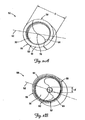
- FIG. 1 is a schematic cutaway view of a hub assembly for use in a medical procedure, such as a catheterization procedure, according to one embodiment of the present invention.
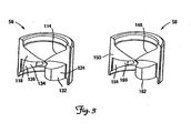
- FIGS. 2A and 2B show proximal and distal perspective views of an assembled seal according to one embodiment of the present invention.
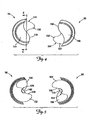
- FIG. 3 shows perspective views of the mating first and second portions of the seal according to one embodiment of the present invention.
- FIG. 4 shows the first and second seal portions from a proximal plan view, according to one embodiment of the present invention.
- FIG. 5 shows the first and second seal portions from a distal plan view, according to one embodiment of the present invention.
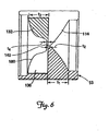
- FIG. 6 is a partial cross-sectional view of the first seal portion according to one embodiment of the present invention.
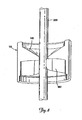
- FIG. 7 is a perspective view of the seal according to one embodiment of the present invention, showing the seal portions partially separated.
- FIG. 8 is a partial perspective view of the seal according to one embodiment of the present invention with a medical device passing therethrough.
- FIG. 9 is a partial proximal plan view of the seal, according to one embodiment of the present invention, with a medical device, such as a therapy lead, passing therethrough.
- FIG. 1 depicts, schematically, a hub assembly 10 for use in a medical procedure, such as a catheterization procedure, according to one embodiment of the present invention.
- the hub assembly 10 includes a body 12 having a lumen 16 therethrough, and a seal 50 according to one embodiment of the present invention.
- the lumen 16 is sized to permit passage of a medical device 18 such as, for example, a therapy lead, guiding catheter, or a guide wire.
- the seal 50 is retained within the hub body 12, and is adapted to maintain a substantially positive fluid seal around the medical device 18 that is passed through the lumen 16.
- the hub 10 may be coupled to another medical device 51 such as a catheter or introducer sheath.
- FIGS. 2A and 2B show proximal and distal perspective views of an assembled seal 50 according to one embodiment of the present invention.
- the seal 50 is, in one embodiment, generally cylindrical with a longitudinal axis 52 and a perimeter 53, and is composed of a first seal portion 56 and a mating second seal portion 58.
- the seal portions 56 and 58 are substantially equivalent in overall size and join at a proximal joint 64 and a distal joint 66 to form a proximal entrance area 70 and a distal exit area 76.
- the seal 50 in one embodiment, is composed of two, separate seal elements, it is particularly adaptable for use in splittable or cuttable medical devices such as splittable hemostasis or bleedback control valves or splittable Introducer sheaths.
- the seal portions 56 and 58 may be attached at or near the seal perimeter using an attachment method that permits the seal 50 to be readily split or cut.
- the shape of the seal 50 will be dictated by the configuration and requirements of the hemostasis valve, hub, or introducer sheath into which the seal 50 is inserted.
- the seat 50 is generally cylindrical with an outer diameter D of from about 0.635 cm (0.250 inches) to about 1.91 cm (0.750 inches). In one embodiment, the diameter D is about 0.152 cm (0.600 inches). In another embodiment, the diameter D is about 1.14 cm (0.450 inches)
- the seal 50 may be made of polyisoprene, In other embodiments, other resilient materials may be used to form the seal 50, including, without limitation, silicone, latex, neoprene, and other rubber-based compounds as will be understood by those of ordinary skill in the art.
- the proximal entrance area 70 is generally conical and has an apex 78 near the longitudinal axis 52
- the distal exit area 76 is concave and may include a generally circular planar portion 82 disposed about and generally perpendicular to the longitudinal axis 52.
- the planar portion 82 has a diameter d of from about 0.076 cm (0.030 inches) to about 0.254 cm (0.100 inches).
- the planar portion 82 has a diameter d of about 0.178 cm (0.070 inches).
- the planar portion 82 has a diameter d of about 0.127 cm (0.050 inches).
- the planar portion 82 may have a non-circular shape (e.g., rectangular, elliptical)
- the planar portion 82 may be centered about the longitudinal axis 52 and, in turn, the apex 78 of the proximal entrance area 70. In another embodiment, either or both of the planar portion 82 and the apex 78 of the proximal entrance area 70 may be offset from the longitudinal axis 52.
- the seal 50 may optionally include means for facilitating retention of the seal 50 within another medical device such as, for example, a hemostasis valve or an introducer sheath.
- Such means may include a proximal retaining ring 90 and/or a distal retaining ring 92.
- FIG. 3 shows perspective views of the first and second seal portions 56 and 58, respectively. Additionally, FIGS. 4 and 5 are proximal ( FIG. 4 ) and distal ( FIG. 5 ) plan views of the seal portions 56 and 58.
- the first seal portion 56 includes a first proximal sealing member 114 having a first mating surface 118, a first projection 132, a first distal wall 134 defining a first recess 136, and a first planar subportion 140.
- the second seal portion 58 includes a second proximal sealing member 146 having a second mating surface 150, a second projection 162, a second distal wall 164 defining a second recess 166, and a second planar subportion 170.
- the mating surfaces 118 and 150 are each contoured to generally form an 'S'-shape. Accordingly, in this embodiment, the proximal joint 64 in the assembled seal 50 is also 'S'-shaped (See FIG. 2A ). In one embodiment, each half of the 'S' of the contoured mating surfaces 118 and 150 may have a radius of curvature of from about 0.318 cm (0.125 inches) to about 0.635 cm (0.250 inches). In one embodiment, the radius of curvature is about 0.381 cm (0.150 inches) In another embodiment, the radius of curvature is about 0.475 cm (0-187 inches). In other embodiments, the mating surfaces 118 and 150 may be configured in other shapes. When the seal portions 56 and 58 are assembled to form the seal 50, the proximal sealing members 114 and 146 form the proximal entrance area 70 (See FIG. 2A ).
- the projections 132 and 162 are generally sized and shaped to be inserted into and to sealingly mate with and engage the recesses 166 and 136, respectively, when the seal portions 56 and 58 are assembled to form the seal 50. When so engaged, the projections 132 and 162 generally form the distal exit area 76 (See FIG. 2B ). In the assembled seal 50, the planar subportions 140 and 170 join to form the generally planar portion 82 (see FIG. 2B ).
- the recesses 136 and 166 are sized and shaped to receive the projections 132 and 162. In one embodiment, when the seal 50 is assembled, substantially all of the adjacent surfaces of the projections 132 and 162 and the recesses 166 and 136 are in sealing contact with one another.
- the projections 132 and 162 and, accordingly, the recesses 136 and 166 are curved, although this is not a requirement of the present invention.
- the projections 132 and 182 may be substantially triangular or rectangular, and the recesses 166 and 136 are shaped to sealingly receive the projections.
- the first proximal sealing member 114 intersects the first projection 132
- the second proximal sealing member 146 intersects the second projection 162, at approximately 90 degree angles and at approximately the longitudinal axis 52.
- the proximal sealing members 114 and 146 overlap the distal joint 66 (see FIG. 2B ), and the projections 132 and 162 overlap the proximal joint 64, at substantially all points other than the longitudinal axis 52.
- FIG. 6 is a partial cross-sectional view of the first seal portion 56 taken along the line X-X In FIG. 4 .
- the features of the second seal portion 58 are generally configured to have the same size and shape as the corresponding features of the first seal portion 56.
- the second proximal sealing member 146, the second projection 162, the second recess 166, and the second planar subportion 170 have generally the same dimensions and shape as the first proximal sealing member 114, the first projection 132, the first recess 136, and the first planar subportion 140, respectively.
- the proximal sealing members 114 and 146 are tapered radially inward, having a thickness t1 near the seal perimeter 53 and a thickness t2 near the apex 78.
- the thickness t1 may range from about 0.191 cm (0.075 inches) to about 0.445 cm (0.175 inches)
- the thickness t2 may range from about 0.013 cm (0.005 inches) to about 0.064 cm (0.025 inches).
- the thickness t1 is about 0.318 cm (0.125 inches) and the thickness t2 is about 0.191 mm (0.0075 inches).
- the projections 132 and 162 are also thicker near the seal perimeter 53 than near the longitudinal axis 52, and transition into the planar subportions 140 and 170.
- the projections 132 and 136 have a thickness t3 near the perimeter 53 that may range from about 0.191 cm (0.075 inches) to about 0.445 cm (0.175 inches), and a thickness t4 of the planar subportions 140 and 170 of from about 0.03 cm (0.005 inches) to about 0.064 cm (0.025 inches).
- the thickness t3 is about 0.318 cm (0.125 inches) and the thickness t4 is about 0.191 mm (0.0075 inches).
- the projections 132 and 162 each have a contoured distal face 180, although in other embodiments, the projections 132 and 162 may have different shapes (e.g., concave) or may have a straight taper similar to the proximal sealing members 114 and 146.
- the thickness t2 of the proximal sealing members 114 and 146 near the apex 78 is thicker than the thickness t4 of the planar subportions 140 and 170.
- the thickness t2 is about 0.0254 cm (0.010 inches) and the thickness t4 is about 0.0127 cm (0.005 inches).
- Table 1 below shows the dimensions, in cm and in inches, discussed above for various exemplary embodiments of a seal 50 according to the present invention.
- D D t1 t2 t3 t4 1 (0.450) (0.050) (0.125) (0.0075) (0.125) (0.0075) 1.14 0.127 0.318 0.0191 0.318 0.0191 2 (0.450) (0.070) (0.125) (0.010) (0.125) (0.010) 1.14 0.178 0.318 0.025 0.318 0.025 3 (0.600) (0.050) (0.125) (0.0075) (0.125) (0.0075) 1.52 0.127 0.318 0.0191 0.318 0.0191 4 (0.600) (0.070) (0.150) (0.010) (0.150) (0.010) 1.52 0.178 0.381 0.025 0.381 0.025 5 (0.300) (0.030) (0.075) (0.005) (0.075) (0.005) 0.762 0.0762 0.191 0.0127 0.191 0.0127 6 (0.500)
- FIG. 7 is a perspective view of the seal 50 according to one embodiment of the present invention, showing the seal portions 56 and 58 partially separated to show how the projections 132 and 162 effectively interlock.
- FIG. 8 is a partial perspective view
- FIG. 9 is a partial proximal plan view, of the seal 50 according to one embodiment of the present invention, with a medical device, such as a therapy lead 200, passing therethrough.
- a medical device such as a therapy lead 200
- FIGS. 8 and 9 Exemplary medical devices that may be accommodated by the seal 50 according to one embodiment of the present invention include, without limitation, guide wires, therapy leads, and guide catheters, with outer diameters ranging from about 0.410 Inches to about 0.170 inches.
- seal 50 of the present invention may be adapted to accommodate larger or smaller diameter medical devices as may be required for a particular procedure.
- the proximal sealing members 114 and 146 and the projections 132 and 162 interact to substantially fully encapsulate the lead 200 as it is passed between the seal potions 56 and 58.
- the contoured shape of the mating surfaces 118 and 150 tends to cause the proximal sealing members 114 and 146 to wrap around the lead 200.
- the projections 132 and 162 tend to wrap around the lead 200 as it passes through the seal 50.
- the proximal sealing members 114 and 146 and projections 132 and 162 substantially fully encapsulate a generally cylindrical medical device that is passed between the seal portions 56 and 58.
- the orientation of the mating surfaces 118 and 150 to the projections 132 and 162 result in at least the proximal sealing members 114 and 146, or the projections 132 and 162, being in sealing contact with the medical device 200 around the entire surface of the device.
- Insertion of a medical device between the seal elements would result in leakage at points approximately 180 degrees apart where the two seal member join.
- the projections 132 and 162 overlap the proximal joint 64 at all points other than the longitudinal axis 52 and accordingly, in one embodiment, the apex 76, which is the point of entry of the medical device through the seal 50.
- the projections 132 and 162 seal around the medical device immediately distal to any areas of separation that may occur in the proximal joint 64.
- the proximal sealing members 114 and 146 overlap the distal joint 66 at all points other than the apex 78. This has the resulting effect of sealing around the regions on the medical device proximal of the points of corner separation in the distal joint 66.
- the inserted medical device, the overlapping proximal sealing members 114 and 146, and the projections 132 and 162 interact to eliminate any pathways for leakage of bodily fluids through the seal 50.
- the projections 132 and 162 also operate to stabilize and hold the seal portions 56 and 58 in alignment when the lead 200 or other medical device is inserted through the seal 50.
- a seal without such Rejections may tend to become misaligned due to, for example, relative translation of the two separate seal components along their joint line, when a device is inserted into or removed from the seal.
- the walls 128 and 158 in the recesses 136 and 166 restrict displacement of the projections 132 and 162, respectively. This in turn restricts relative movement of the seal portions 56 and 58.
- the interlocking design of the projections 132 and 162 and the recesses 136 and 166, respectively similarly restricts rotational movement of the seal elements 70 and 76 relative to each other.
- the stabilizing effect of the projections 132 and 162 is further promoted by their profiles. Near the longitudinal axis 52, the projections 132 and 162 are relatively thin, which promotes effective sealing while at the same time reduces resistance to movement of the lead 200 or other medical device through the seal 50. This provides a beneficial combination of effective sealing without unduly restricting the travel of the medical device through the seal 50. At the same time, the thicker portions of the projections 132 and 162 near the perimeter of the seal 50 beneficially stiffens the projections which further inhibits misalignment of the seal portions 56 and 58.
- the geometry of the seal 50 advantageously promotes centering the medical device, such as the lead 200, as it is passed through the seal 50.
- the orientation of the projections 132 and 162 at approximately 90 degrees relative to the proximal joint 64 inhibits the lead 200 from sliding along the proximal joint 64, as would tend to occur if the projections 132 and 162 were not present. Accordingly, the projections 132 and 162 operate to maintain the lead 200 or other medical device at a position at or near the longitudinal axis 52 (see FIG. 2A ).
Abstract
Description
- The present invention relates generally to the field of medical instruments, and more particularly to hemostasis seals for use during medical procedures.
- Various medical procedures require the introduction of one or more medical instruments into arteries or veins so that the medical instruments may be advanced to a body location requiring diagnosis or treatment. For example, a guide catheter may be advanced through the patient's vasculature to a desired treatment location, such as the right atrium of the patient's heart, for delivery of a cardiac lead. A mechanism (e.g., a hemostasis valve) including a hemostasis seal may be located at the proximal end of the guide catheter to control or inhibit the flow of blood out of the guide catheter lumen. A cardiac lead or other device (e.g., a guide wire) may be inserted through the seal and the guide catheter lumen and into the patient's vasculature, and the seal Inhibits blood flow around the lead.
- The seal should accommodate medical devices (e.g., leads, catheters and guide wires) of varying diameters without unduly restricting the movement of the device, yet still effectively seal against the flow of bodily fluids. In addition, the seal may advantageously be designed to be splittable to facilitate removal of the guide catheter while leaving the Inner medical device (e.g., guide wire or lead) in place in the patient's body.
- Accordingly, there is a need for a splittable or cuttable hemostasis seal which effectively seals against leakage of bodily fluids without unduly resisting the insertion and retraction of elongated cylindrical medical devices of varying diameters.
- The present invention, according to one embodiment, is a hemostasis seal configured to permit passage of a medical device. The seal includes a first resilient seal portion having a first proximal seal member with a first mating surface, a first projecting portion, and a first receiving portion. The seal also includes a second resilient seal portion having a second proximal seal portion with a second mating surface, a second projecting portion, and a second receiving portion. The first mating surface is configured to mate with the second mating surface to form a first fluid seal with respect to the medical device. In addition, the first and second projecting portions are adapted to mate with and sealingly engage the second and first receiving portions, respectively, to form a second fluid seal with respect to the medical device.
- In another embodiment, the present invention is a hemostasis seal configured to permit passage of a medical device, and includes a first resilient seal portion with a first mating surface that includes a projecting portion; and a second resilient seal portion with a second mating surface configured to mate with the first mating surface. The second mating surface includes a receiving portion adapted to mate with the projecting portion. The seal is configured such that the first and second seal portions seal around substantially the entire circumferential surface of the medical device when it is passed between the first and second seal portions.
- The present invention, in yet another embodiment, Is a hemostasis seal configured to permit passage of a medical device. The seal includes a pair of mating seal portions each having a proximal sealing member, a distal projecting member, and a distal receiving portion. The distal receiving portion of each seal portion is sized and shaped to sealingly receive the projecting member of the mating seal portion, and the proximal sealing members and the distal projecting members are configured to sealingly and slidably engage the medical device about substantially an entire circumferential surface thereof when the medical device is passed through the seal.
- While multiple embodiments are disclosed, still other embodiments of the present invention will become apparent to those skilled in the art from the following detailed description, which shows and describes illustrative embodiments of the invention. Accordingly, the drawings and detailed description are to be regarded as illustrative in nature and not restrictive.
-
FIG. 1 is a schematic cutaway view of a hub assembly for use in a medical procedure, such as a catheterization procedure, according to one embodiment of the present invention. -
FIGS. 2A and 2B show proximal and distal perspective views of an assembled seal according to one embodiment of the present invention. -
FIG. 3 shows perspective views of the mating first and second portions of the seal according to one embodiment of the present invention. -
FIG. 4 shows the first and second seal portions from a proximal plan view, according to one embodiment of the present invention. -
FIG. 5 shows the first and second seal portions from a distal plan view, according to one embodiment of the present invention. -
FIG. 6 is a partial cross-sectional view of the first seal portion according to one embodiment of the present invention. -
FIG: 7 is a perspective view of the seal according to one embodiment of the present invention, showing the seal portions partially separated. -
FIG. 8 is a partial perspective view of the seal according to one embodiment of the present invention with a medical device passing therethrough. -
FIG. 9 is a partial proximal plan view of the seal, according to one embodiment of the present invention, with a medical device, such as a therapy lead, passing therethrough. - While the invention is amenable to various modifications and alternative forms, specific embodiments have been shown by way of example in the drawings and are described in detail below. The intention, however, is not to limit the invention to the particular embodiments described. On the contrary, the invention is intended to cover all modifications, equivalents, and alternatives falling within the scope of the invention as defined by the appended claims.
-
FIG. 1 depicts, schematically, ahub assembly 10 for use in a medical procedure, such as a catheterization procedure, according to one embodiment of the present invention. As can be seen inFIG. 1 , thehub assembly 10 includes abody 12 having alumen 16 therethrough, and aseal 50 according to one embodiment of the present invention. Thelumen 16 is sized to permit passage of amedical device 18 such as, for example, a therapy lead, guiding catheter, or a guide wire. Theseal 50 is retained within thehub body 12, and is adapted to maintain a substantially positive fluid seal around themedical device 18 that is passed through thelumen 16. Thehub 10 may be coupled to anothermedical device 51 such as a catheter or introducer sheath. -
FIGS. 2A and 2B show proximal and distal perspective views of an assembledseal 50 according to one embodiment of the present invention. As shown inFIGS. 2A and 2B , theseal 50 is, in one embodiment, generally cylindrical with alongitudinal axis 52 and aperimeter 53, and is composed of afirst seal portion 56 and a matingsecond seal portion 58. Theseal portions proximal joint 64 and adistal joint 66 to form aproximal entrance area 70 and adistal exit area 76. Because theseal 50, in one embodiment, is composed of two, separate seal elements, it is particularly adaptable for use in splittable or cuttable medical devices such as splittable hemostasis or bleedback control valves or splittable Introducer sheaths. In one embodiment, theseal portions seal 50 to be readily split or cut. - In general, the shape of the
seal 50 will be dictated by the configuration and requirements of the hemostasis valve, hub, or introducer sheath into which theseal 50 is inserted. In one embodiment theseat 50 is generally cylindrical with an outer diameter D of from about 0.635 cm (0.250 inches) to about 1.91 cm (0.750 inches). In one embodiment, the diameter D is about 0.152 cm (0.600 inches). In another embodiment, the diameter D is about 1.14 cm (0.450 inches) AlthoughFIGS. 2A and 2B depict acylindrical seal 50, this is not a requirement To the contrary, other shapes (e.g., rectangular, elliptical) are within the scope of the present invention. - In one embodiment, the
seal 50 may be made of polyisoprene, In other embodiments, other resilient materials may be used to form theseal 50, including, without limitation, silicone, latex, neoprene, and other rubber-based compounds as will be understood by those of ordinary skill in the art. - In one embodiment, shown in
FIGS. 2A and 2B , theproximal entrance area 70 is generally conical and has anapex 78 near thelongitudinal axis 52, and thedistal exit area 76 is concave and may include a generally circularplanar portion 82 disposed about and generally perpendicular to thelongitudinal axis 52. In one embodiment, theplanar portion 82 has a diameter d of from about 0.076 cm (0.030 inches) to about 0.254 cm (0.100 inches). In one embodiment, theplanar portion 82 has a diameter d of about 0.178 cm (0.070 inches). In another embodiment, theplanar portion 82 has a diameter d of about 0.127 cm (0.050 inches). In other embodiments, theplanar portion 82 may have a non-circular shape (e.g., rectangular, elliptical) - In one embodiment, the
planar portion 82 may be centered about thelongitudinal axis 52 and, in turn, theapex 78 of theproximal entrance area 70. In another embodiment, either or both of theplanar portion 82 and theapex 78 of theproximal entrance area 70 may be offset from thelongitudinal axis 52. - The
seal 50 may optionally include means for facilitating retention of theseal 50 within another medical device such as, for example, a hemostasis valve or an introducer sheath. Such means may include aproximal retaining ring 90 and/or adistal retaining ring 92. -
FIG. 3 shows perspective views of the first andsecond seal portions FIGS. 4 and 5 are proximal (FIG. 4 ) and distal (FIG. 5 ) plan views of theseal portions FIGS. 3 ,4 and 5 , thefirst seal portion 56 includes a firstproximal sealing member 114 having afirst mating surface 118, afirst projection 132, a firstdistal wall 134 defining afirst recess 136, and a firstplanar subportion 140. Thesecond seal portion 58 includes a secondproximal sealing member 146 having asecond mating surface 150, asecond projection 162, a seconddistal wall 164 defining asecond recess 166, and a secondplanar subportion 170. - In one embodiment, the mating surfaces 118 and 150 are each contoured to generally form an 'S'-shape. Accordingly, in this embodiment, the proximal joint 64 in the assembled
seal 50 is also 'S'-shaped (SeeFIG. 2A ). In one embodiment, each half of the 'S' of the contoured mating surfaces 118 and 150 may have a radius of curvature of from about 0.318 cm (0.125 inches) to about 0.635 cm (0.250 inches). In one embodiment, the radius of curvature is about 0.381 cm (0.150 inches) In another embodiment, the radius of curvature is about 0.475 cm (0-187 inches). In other embodiments, the mating surfaces 118 and 150 may be configured in other shapes. When theseal portions seal 50, theproximal sealing members FIG. 2A ). - In one embodiment, the
projections recesses seal portions seal 50. When so engaged, theprojections FIG. 2B ). In the assembledseal 50, the planar subportions 140 and 170 join to form the generally planar portion 82 (seeFIG. 2B ). - The
recesses projections seal 50 is assembled, substantially all of the adjacent surfaces of theprojections recesses - In one embodiment, as shown in
FIGS. 3 ,4 and 5 , theprojections recesses projections 132 and 182 may be substantially triangular or rectangular, and therecesses - As shown in
FIGS. 4 and 5 , in one embodiment, the firstproximal sealing member 114 intersects thefirst projection 132, and the secondproximal sealing member 146 intersects thesecond projection 162, at approximately 90 degree angles and at approximately thelongitudinal axis 52. As a result, theproximal sealing members FIG. 2B ), and theprojections longitudinal axis 52. As discussed below, this results in sealing around substantially the entire circumferential surface of a medical device (e.g., a cardiac lead) that is inserted through the seal. -
FIG. 6 is a partial cross-sectional view of thefirst seal portion 56 taken along the line X-X InFIG. 4 . It should be understood that, although not shown InFIG. 6 , the features of thesecond seal portion 58 are generally configured to have the same size and shape as the corresponding features of thefirst seal portion 56. For example, the secondproximal sealing member 146, thesecond projection 162, thesecond recess 166, and the secondplanar subportion 170 have generally the same dimensions and shape as the firstproximal sealing member 114, thefirst projection 132, thefirst recess 136, and the firstplanar subportion 140, respectively. - Thus, as shown in
FIG. 6 , theproximal sealing members seal perimeter 53 and a thickness t2 near the apex 78. In one embodiment, the thickness t1 may range from about 0.191 cm (0.075 inches) to about 0.445 cm (0.175 inches), and the thickness t2 may range from about 0.013 cm (0.005 inches) to about 0.064 cm (0.025 inches). In one embodiment, the thickness t1 is about 0.318 cm (0.125 inches) and the thickness t2 is about 0.191 mm (0.0075 inches). - As further shown in
FIG. 6 , theprojections seal perimeter 53 than near thelongitudinal axis 52, and transition into the planar subportions 140 and 170. In one embodiment, theprojections perimeter 53 that may range from about 0.191 cm (0.075 inches) to about 0.445 cm (0.175 inches), and a thickness t4 of the planar subportions 140 and 170 of from about 0.03 cm (0.005 inches) to about 0.064 cm (0.025 inches). In one embodiment, the thickness t3 is about 0.318 cm (0.125 inches) and the thickness t4 is about 0.191 mm (0.0075 inches). - In the embodiment shown in
FIG. 6 , theprojections distal face 180, although in other embodiments, theprojections proximal sealing members - In one embodiment, the thickness t2 of the
proximal sealing members - Table 1 below shows the dimensions, in cm and in inches, discussed above for various exemplary embodiments of a
seal 50 according to the present invention.D D t1 t2 t3 t4 1 (0.450) (0.050) (0.125) (0.0075) (0.125) (0.0075) 1.14 0.127 0.318 0.0191 0.318 0.0191 2 (0.450) (0.070) (0.125) (0.010) (0.125) (0.010) 1.14 0.178 0.318 0.025 0.318 0.025 3 (0.600) (0.050) (0.125) (0.0075) (0.125) (0.0075) 1.52 0.127 0.318 0.0191 0.318 0.0191 4 (0.600) (0.070) (0.150) (0.010) (0.150) (0.010) 1.52 0.178 0.381 0.025 0.381 0.025 5 (0.300) (0.030) (0.075) (0.005) (0.075) (0.005) 0.762 0.0762 0.191 0.0127 0.191 0.0127 6 (0.500) (0.045) (0.125) 0.010 0.125 (0.005) 1.27 0.114 0.318 (0.025) (0.318) 0.0127 7 (0.750) (0.080) (0.150 ) (0.015) (0.150) (0.010) 1.91 0.203 0.381 0.0381 0.381 0.025 8 (0.750) (0.100) (0.175) (0.025) (0.175) (0.025) 1.91 0.254 0.445 0.0635 0.445 0.0635 -
FIG. 7 is a perspective view of theseal 50 according to one embodiment of the present invention, showing theseal portions projections -
FIG. 8 is a partial perspective view, andFIG. 9 is a partial proximal plan view, of theseal 50 according to one embodiment of the present invention, with a medical device, such as atherapy lead 200, passing therethrough. For clarity, only thesecond seal portion 58 is shown inFIGS. 8 and9 . Exemplary medical devices that may be accommodated by theseal 50 according to one embodiment of the present invention include, without limitation, guide wires, therapy leads, and guide catheters, with outer diameters ranging from about 0.410 Inches to about 0.170 inches. As will be apparent to those of ordinary skill in the art, the foregoing types of medical devices and the corresponding ranges of diameters are merely exemplary, and theseal 50 of the present invention may be adapted to accommodate larger or smaller diameter medical devices as may be required for a particular procedure. - As shown in
FIGS. 8 and9 , theproximal sealing members projections lead 200 as it is passed between theseal potions proximal sealing members lead 200. Similarly, in one embodiment, theprojections lead 200 as it passes through theseal 50. Working together, theproximal sealing members projections seal portions - Additionally, the orientation of the mating surfaces 118 and 150 to the
projections proximal sealing members projections medical device 200 around the entire surface of the device. With aseal lacking projections FIGS. 4-7 , however, theprojections longitudinal axis 52 and accordingly, in one embodiment, the apex 76, which is the point of entry of the medical device through theseal 50. Thus, theprojections proximal sealing members proximal sealing members projections seal 50. - The
projections seal portions lead 200 or other medical device is inserted through theseal 50. A seal without such Rejections may tend to become misaligned due to, for example, relative translation of the two separate seal components along their joint line, when a device is inserted into or removed from the seal. In the present invention, however, according to one embodiment, thewalls recesses projections seal portions projections recesses seal elements - The stabilizing effect of the
projections longitudinal axis 52, theprojections lead 200 or other medical device through theseal 50. This provides a beneficial combination of effective sealing without unduly restricting the travel of the medical device through theseal 50. At the same time, the thicker portions of theprojections seal 50 beneficially stiffens the projections which further inhibits misalignment of theseal portions - In addition, the geometry of the
seal 50 advantageously promotes centering the medical device, such as thelead 200, as it is passed through theseal 50. The orientation of theprojections projections projections lead 200 or other medical device at a position at or near the longitudinal axis 52 (seeFIG. 2A ). - Various modifications and additions can be made to the exemplary embodiments discussed without departing from the scope of the present invention. For example, while the embodiments described above refer to particular features, the scope of this invention also includes embodiments having different combinations of features and embodiments that do not include all of the described features. Accordingly, the scope of the present invention is intended to embrace all such alternatives, modifications, and variations as fall within the scope of the claims, together with all equivalents thereof.
Claims (15)
- A hemostasis seal (50) configured to permit passage of a medical device therethrough, the seal comprising :a first resilient seal portion (56) including a first sealing member (114) having a first mating surface (118), a first projecting portion (132), and a first receiving portion (136); anda second resilient seal portion (58) including a second sealing member (146) having a second mating surface (150), a second projecting portion (162), and a second receiving portion (166),wherein the first mating surface is adapted to mate with the second mating surface to form a first fluid seal with respect to the medical device, andwherein the first and second projecting portions are adapted to mate with and sealingly engage the second and first receiving portions, respectively, to form a second fluid seal with respect to the medical device.
- The seal of claim 1 wherein the seal is cylindrical with a perimeter and a longitudinal axis, and wherein the first and second sealing members mate to form an entrance area.
- The seal of claim 2 wherein the entrance area is generally conical with an apex near the longitudinal axis, and wherein the first and second sealing members each have a first thickness near the seal perimeter of from about 0.191 cm (0.075 inches) to about 0.445 cm (0.175 inches), and a second thickness at the apex of from about 0.0127cm (0.005 inches) to about 0.0635 cm (0.025 inches).
- The seal of claim 3 wherein the first thickness is about 0.318 cm (0.125 inches) and the second thickness is about 0.0191 cm (0.0075 inches).
- The seal of aspect 4 wherein the first thickness is about 0.381 cm (0.150 inches) and the second thickness is about 0.025 cm (0.010 inches).
- The seal of claim 2 wherein the first and second projecting portions each have a third thickness near the seal perimeter and a fourth thickness near the longitudinal axis, wherein the third thickness is grater than the fourth thickness.
- The seal of claim 6 wherein the projecting portions and receiving portions mate to form an exit area including a generally planar portion disposed about and oriented generally orthogonal to the longitudinal axis.
- The seal of claim 7 wherein the third thickness is from about 0.191 cm (0.075 inches) to about 0.445 cm (0.175 inches) and the fourth thickness is from about 0.0127cm (0.005 inches) to about 0.0635 cm (0.025 inches).
- The seal of claim 8 wherein the third thickness is about 0.0318 cm (0.0125 inches) and the fourth thickness is about 0.0191 cm (0.0075 inches).
- The seal of claim 8 wherein the third thickness is about 0.381 cm (0.150 inches) and the fourth thickness is about 0.025 cm (0.010 inches).
- The seal of claim 3 wherein the first and second projecting portions each have a third thickness near the seal perimeter of from about 0.191 cm (0.075 inches) to about 0.445 cm (0.175 inches), and a fourth thickness near the longitudinal axis of from about 0.0127 cm (0.005 inches) to about 0.0635 cm (0.025 inches).
- The seal of claim 11 wherein the first thickness is about 0.318 cm (0.125 inches), the second thickness is about 0.0191 cm (0.0075 inches) the third thickness is about 0.318 cm (0.125 inches), and the fourth thickness is about 0.0191 cm (0.0075 inches).
- The seal of claim 1 wherein the projecting portions interlock to form the second fluid seal with respect to the medical device.
- The seal of claim 1 wherein the first and second mating surfaces are generally "S"-shaped.
- The seal of claim 2 wherein the first projecting portion is oriented generally perpendicular to the first mating surface near the longitudinal axis, and wherein the second projecting portion is oriented generally perpendicular to the second mating surface near the longitudinal axis.
Applications Claiming Priority (2)
| Application Number | Priority Date | Filing Date | Title |
|---|---|---|---|
| US11/257,201 US7731694B2 (en) | 2005-10-24 | 2005-10-24 | Hemostasis seal |
| PCT/US2006/060159 WO2007067826A2 (en) | 2005-10-24 | 2006-10-23 | Hemostasis seal |
Publications (2)
| Publication Number | Publication Date |
|---|---|
| EP1951359A2 EP1951359A2 (en) | 2008-08-06 |
| EP1951359B1 true EP1951359B1 (en) | 2011-02-23 |
Family
ID=38004787
Family Applications (1)
| Application Number | Title | Priority Date | Filing Date |
|---|---|---|---|
| EP06848407A Not-in-force EP1951359B1 (en) | 2005-10-24 | 2006-10-23 | Hemostasis seal |
Country Status (7)
| Country | Link |
|---|---|
| US (2) | US7731694B2 (en) |
| EP (1) | EP1951359B1 (en) |
| JP (1) | JP5001290B2 (en) |
| AT (1) | ATE499140T1 (en) |
| DE (1) | DE602006020321D1 (en) |
| ES (1) | ES2359942T3 (en) |
| WO (1) | WO2007067826A2 (en) |
Families Citing this family (32)
| Publication number | Priority date | Publication date | Assignee | Title |
|---|---|---|---|---|
| US7731694B2 (en) * | 2005-10-24 | 2010-06-08 | Cardiac Pacemakers, Inc. | Hemostasis seal |
| DE102006015690A1 (en) * | 2006-03-27 | 2007-10-11 | Aesculap Ag & Co. Kg | Surgical sealing element, surgical seal and surgical sealing system |
| JP5235017B2 (en) * | 2006-08-25 | 2013-07-10 | テレフレックス メディカル インコーポレイテッド | Floating seal device with frame |
| JP4994775B2 (en) | 2006-10-12 | 2012-08-08 | 日本コヴィディエン株式会社 | Needle point protector |
| PT2164553T (en) * | 2007-06-22 | 2018-06-18 | Medical Components Inc | Hub for a tearaway sheath assembly with hemostasis valve |
| US20090012476A1 (en) * | 2007-07-05 | 2009-01-08 | Galt Medical Corporation | Hemostasis valve for a catheter introducer |
| EP2195063B1 (en) * | 2007-09-18 | 2019-08-07 | Medical Components, Inc. | Tearaway sheath assembly with split hemostasis valve |
| PL2262568T3 (en) * | 2008-03-14 | 2020-04-30 | Medical Components, Inc. | Tearaway introducer sheath with hemostasis valve |
| US7938809B2 (en) * | 2008-04-14 | 2011-05-10 | Merit Medical Systems, Inc. | Quick release hemostasis valve |
| DE102008033375A1 (en) | 2008-07-09 | 2010-01-14 | Aesculap Ag | Surgical sealing element holder for holding a surgical sealing element and surgical sealing system |
| DE102008033374A1 (en) | 2008-07-09 | 2010-01-14 | Aesculap Ag | Surgical protection device for a surgical sealing element and surgical sealing system |
| US8267897B2 (en) * | 2010-01-06 | 2012-09-18 | W. L. Gore & Associates, Inc. | Center twist hemostatic valve |
| US9522266B2 (en) | 2011-02-28 | 2016-12-20 | Gmedix, Inc. | Hemostasis sealing device |
| ITRM20110169A1 (en) * | 2011-04-01 | 2012-10-02 | Mysui S R L | HOLDING DEVICE FOR TROCAR AND RELATED TROCAR. |
| ES2662356T3 (en) | 2011-04-27 | 2018-04-06 | Kpr U.S., Llc | Safety IV catheter assemblies |
| WO2013048768A1 (en) | 2011-09-26 | 2013-04-04 | Covidien Lp | Safety iv catheter and needle assembly |
| WO2013048975A1 (en) | 2011-09-26 | 2013-04-04 | Covidien Lp | Safety catheter |
| WO2013056223A1 (en) | 2011-10-14 | 2013-04-18 | Covidien Lp | Safety iv catheter assembly |
| US9980813B2 (en) | 2014-04-28 | 2018-05-29 | Cook Medical Technologies Llc | Selective fluid barrier valve device and method of treatment |
| US10449331B2 (en) * | 2015-05-13 | 2019-10-22 | B. Braun Melsungen Ag | Catheter devices with seals and related methods |
| DE102016106626A1 (en) * | 2016-04-11 | 2017-10-12 | Joline Gmbh & Co. Kg | Introducer catheter with a valve body |
| US10391292B2 (en) | 2016-06-15 | 2019-08-27 | Surmodics, Inc. | Hemostasis sealing device with constriction ring |
| US10557552B2 (en) | 2016-11-21 | 2020-02-11 | Cardiac Pacemakers, Inc. | Trough seal |
| EP4252998A3 (en) | 2016-12-08 | 2024-01-31 | Abiomed, Inc. | Overmold technique for peel-away introducer design |
| US10758719B2 (en) | 2016-12-15 | 2020-09-01 | Surmodics, Inc. | Low-friction sealing devices |
| CN110612140B (en) | 2017-03-13 | 2022-10-18 | 波士顿科学有限公司 | Hemostatic valve and methods of making and using same |
| WO2018169670A1 (en) | 2017-03-13 | 2018-09-20 | Boston Scientific Limited | Hemostasis valves and methods for making and using hemostasis valves |
| WO2018169660A1 (en) | 2017-03-13 | 2018-09-20 | Boston Scientific Limited | Hemostasis valves and methods for making and using hemostasis valves |
| CN111601635B (en) | 2017-09-12 | 2023-01-10 | 波士顿科学有限公司 | Hemostatic valve and methods for making and using a hemostatic valve |
| SG11202003104SA (en) | 2017-11-06 | 2020-05-28 | Abiomed Inc | Peel away hemostasis valve |
| KR20210020911A (en) | 2018-05-16 | 2021-02-24 | 아비오메드, 인크. | Detachable sheath assembly |
| WO2024030780A1 (en) * | 2022-08-01 | 2024-02-08 | Terumo Corporation | Hemostasis valve |
Family Cites Families (46)
| Publication number | Priority date | Publication date | Assignee | Title |
|---|---|---|---|---|
| US3113586A (en) * | 1962-09-17 | 1963-12-10 | Physio Control Company Inc | Artificial heart valve |
| US4655752A (en) | 1983-10-24 | 1987-04-07 | Acufex Microsurgical, Inc. | Surgical cannula |
| US4929235A (en) | 1985-07-31 | 1990-05-29 | Universal Medical Instrument Corp. | Self-sealing percutaneous tube introducer |
| US4747840A (en) * | 1986-09-17 | 1988-05-31 | Ladika Joseph E | Selective pulmonary arteriograph catheter |
| US4798594A (en) | 1987-09-21 | 1989-01-17 | Cordis Corporation | Medical instrument valve |
| US4895565A (en) | 1987-09-21 | 1990-01-23 | Cordis Corporation | Medical instrument valve |
| US4909798A (en) | 1987-11-12 | 1990-03-20 | Daig Corporation | Universal hemostasis cannula |
| DE3809127C1 (en) | 1988-03-18 | 1989-04-13 | B. Braun Melsungen Ag, 3508 Melsungen, De | |
| US4895346A (en) | 1988-05-02 | 1990-01-23 | The Kendall Company | Valve assembly |
| US5000745A (en) | 1988-11-18 | 1991-03-19 | Edward Weck Incorporated | Hemostatis valve |
| US5149327A (en) | 1989-09-05 | 1992-09-22 | Terumo Kabushiki Kaisha | Medical valve, catheter with valve, and catheter assembly |
| US5226879A (en) * | 1990-03-01 | 1993-07-13 | William D. Ensminger | Implantable access device |
| US5114408A (en) | 1990-10-18 | 1992-05-19 | Daig Corporation | Universal hemostasis valve having improved sealing characteristics |
| JPH04170966A (en) | 1990-11-01 | 1992-06-18 | Nippon Sherwood Kk | Valvular body for catheter introducer blood stop valve |
| US5125903A (en) | 1991-08-01 | 1992-06-30 | Medtronic, Inc. | Hemostasis valve |
| US5743884A (en) | 1992-12-17 | 1998-04-28 | Hasson; Harrith M. | Sealing structure for medical instrument |
| US5385552A (en) | 1993-03-11 | 1995-01-31 | Habley Medical Technology Corporation | Trocar with overlapping seal elements |
| US5330437A (en) * | 1993-11-12 | 1994-07-19 | Ethicon Endo-Surgery | Self sealing flexible elastomeric valve and trocar assembly for incorporating same |
| US5520655A (en) | 1994-07-15 | 1996-05-28 | Cordis Corporation | Catheter hemostasis valve |
| US5643227A (en) | 1995-01-19 | 1997-07-01 | Stevens; Robert C. | Hemostasis cannula valve apparatus and method of using same |
| US5997515A (en) | 1995-05-19 | 1999-12-07 | General Surgical Innovations, Inc. | Screw-type skin seal with inflatable membrane |
| US5693025A (en) | 1995-07-14 | 1997-12-02 | Merit Medical Systems, Inc. | Adapter with hemostasis valve and rotatable connector |
| US6142981A (en) | 1997-01-07 | 2000-11-07 | Daig Corporation | Hemostasis valve |
| US6083207A (en) * | 1998-12-08 | 2000-07-04 | Daig Corporation | Partitioned hemostasis valve system |
| US5935112A (en) | 1997-10-15 | 1999-08-10 | Stevens; Brian W. | Hemostasis valve with catheter/guidewire seals |
| US7226433B2 (en) | 1998-02-06 | 2007-06-05 | Possis Medical, Inc. | Thrombectomy catheter device having a self-sealing hemostasis valve |
| US6634364B2 (en) | 2000-12-15 | 2003-10-21 | Cardiac Pacemakers, Inc. | Method of deploying a ventricular lead containing a hemostasis mechanism |
| US6086570A (en) | 1998-09-29 | 2000-07-11 | A-Med Systems, Inc. | Hemostasis valve with membranes having offset apertures |
| US6623460B1 (en) | 1998-12-08 | 2003-09-23 | St. Jude Medical, Daig Division | Partitioned hemostasis valve system |
| US6331176B1 (en) | 1999-03-11 | 2001-12-18 | Advanced Cardiovascular Systems, Inc. | Bleed back control assembly and method |
| JP2000316986A (en) * | 1999-05-07 | 2000-11-21 | Goodman Co Ltd | Y-connector |
| US6702828B2 (en) | 1999-09-01 | 2004-03-09 | Converge Medical, Inc. | Anastomosis system |
| US6632200B2 (en) * | 2000-01-25 | 2003-10-14 | St. Jude Medical, Daig Division | Hemostasis valve |
| US6551283B1 (en) * | 2000-01-25 | 2003-04-22 | St. Jude Medical, Daig Division | Hemostasis valve |
| US6602240B2 (en) | 2000-02-15 | 2003-08-05 | Thomas J. Fogarty | Method and device for maintaining a seal |
| US20020072712A1 (en) | 2000-10-12 | 2002-06-13 | Nool Jeffrey A. | Medical wire introducer and protective sheath |
| US6702255B2 (en) | 2001-11-08 | 2004-03-09 | Edwards Lifesciences Corporation | H-shape duckbill hemostasis valve assembly including guide wire seal |
| US7549979B2 (en) * | 2002-02-04 | 2009-06-23 | Benlan, Inc. | Safety needle device |
| US6723073B2 (en) | 2002-09-06 | 2004-04-20 | Cardiac Pacemakers, Inc. | Hemostasis valve for use with a left ventricular pacing lead |
| EP1633413A2 (en) | 2003-06-18 | 2006-03-15 | Pressure Products Medical Supplies, Inc. | A method and apparatus with a splittable hemostatic valve with a variable aperture |
| US20040267202A1 (en) | 2003-06-26 | 2004-12-30 | Potter Daniel J. | Tearable hemostasis valve and splittable sheath |
| US7241276B2 (en) | 2003-08-06 | 2007-07-10 | Trivascular, Inc. | Passive hemostatic sheath valve |
| EP1740257A1 (en) | 2004-04-09 | 2007-01-10 | Cook Vascular Incorporated | Modular hemostatic valve |
| US7371227B2 (en) * | 2004-12-17 | 2008-05-13 | Ethicon Endo-Surgery, Inc. | Trocar seal assembly |
| US7481795B2 (en) * | 2004-12-17 | 2009-01-27 | Ethicon Endo-Surgery, Inc. | Circumferential trocar seal assembly |
| US7731694B2 (en) * | 2005-10-24 | 2010-06-08 | Cardiac Pacemakers, Inc. | Hemostasis seal |
-
2005
- 2005-10-24 US US11/257,201 patent/US7731694B2/en not_active Expired - Fee Related
-
2006
- 2006-10-23 EP EP06848407A patent/EP1951359B1/en not_active Not-in-force
- 2006-10-23 AT AT06848407T patent/ATE499140T1/en not_active IP Right Cessation
- 2006-10-23 ES ES06848407T patent/ES2359942T3/en active Active
- 2006-10-23 JP JP2008536658A patent/JP5001290B2/en not_active Expired - Fee Related
- 2006-10-23 DE DE602006020321T patent/DE602006020321D1/en active Active
- 2006-10-23 WO PCT/US2006/060159 patent/WO2007067826A2/en active Application Filing
-
2010
- 2010-05-17 US US12/781,433 patent/US8048033B2/en not_active Expired - Fee Related
Also Published As
| Publication number | Publication date |
|---|---|
| US8048033B2 (en) | 2011-11-01 |
| JP5001290B2 (en) | 2012-08-15 |
| US20070106262A1 (en) | 2007-05-10 |
| ES2359942T3 (en) | 2011-05-30 |
| JP2009512509A (en) | 2009-03-26 |
| US20100292638A1 (en) | 2010-11-18 |
| EP1951359A2 (en) | 2008-08-06 |
| US7731694B2 (en) | 2010-06-08 |
| DE602006020321D1 (en) | 2011-04-07 |
| WO2007067826A2 (en) | 2007-06-14 |
| WO2007067826A3 (en) | 2007-08-02 |
| ATE499140T1 (en) | 2011-03-15 |
Similar Documents
| Publication | Publication Date | Title |
|---|---|---|
| EP1951359B1 (en) | Hemostasis seal | |
| US6702255B2 (en) | H-shape duckbill hemostasis valve assembly including guide wire seal | |
| EP1905476B1 (en) | Acute hemodialysis catheter assembly | |
| EP3352839B1 (en) | Cross slit gasket for introducer sheath | |
| US20090012476A1 (en) | Hemostasis valve for a catheter introducer | |
| JPS6324958A (en) | Catheter assembly | |
| US20060271012A1 (en) | Catheter port assembly for extracorporeal treatment | |
| BR112014008357B1 (en) | catheter set | |
| US20210338942A1 (en) | Flow control plug securement | |
| TW200946159A (en) | Tearaway introducer sheath with hemostasis valve | |
| US20110087093A1 (en) | Valve configurations for implantable medical devices | |
| BR112019002082B1 (en) | INTRAVENOUS CATHETER APPLIANCE WITH SAFETY FUNCTION AND PRESSURE CONTROLLED VALVE ELEMENT | |
| US11890447B2 (en) | Methods and devices for vascular access | |
| JP2021515687A (en) | Intravenous catheter assembly | |
| JP2024026485A (en) | Catheter assembly and related methods | |
| CA3208826A1 (en) | Methods and devices for vascular access | |
| EP2979720B1 (en) | Medical tube | |
| US20230016752A1 (en) | Gasket with external sealing features for introducer sheath | |
| US20210330939A1 (en) | Preloaded Stylet Valve Compatibility | |
| WO2024006922A2 (en) | Methods and devices for vascular access |
Legal Events
| Date | Code | Title | Description |
|---|---|---|---|
| PUAI | Public reference made under article 153(3) epc to a published international application that has entered the european phase |
Free format text: ORIGINAL CODE: 0009012 |
|
| 17P | Request for examination filed |
Effective date: 20080502 |
|
| AK | Designated contracting states |
Kind code of ref document: A2 Designated state(s): AT BE BG CH CY CZ DE DK EE ES FI FR GB GR HU IE IS IT LI LT LU LV MC NL PL PT RO SE SI SK TR |
|
| RIN1 | Information on inventor provided before grant (corrected) |
Inventor name: BECKER, NEIL, M. Inventor name: ANDREWS, CHRISTOPHER, C. |
|
| GRAP | Despatch of communication of intention to grant a patent |
Free format text: ORIGINAL CODE: EPIDOSNIGR1 |
|
| GRAS | Grant fee paid |
Free format text: ORIGINAL CODE: EPIDOSNIGR3 |
|
| GRAA | (expected) grant |
Free format text: ORIGINAL CODE: 0009210 |
|
| AK | Designated contracting states |
Kind code of ref document: B1 Designated state(s): AT BE BG CH CY CZ DE DK EE ES FI FR GB GR HU IE IS IT LI LT LU LV MC NL PL PT RO SE SI SK TR |
|
| REG | Reference to a national code |
Ref country code: GB Ref legal event code: FG4D |
|
| REG | Reference to a national code |
Ref country code: CH Ref legal event code: EP |
|
| REG | Reference to a national code |
Ref country code: IE Ref legal event code: FG4D |
|
| REF | Corresponds to: |
Ref document number: 602006020321 Country of ref document: DE Date of ref document: 20110407 Kind code of ref document: P |
|
| REG | Reference to a national code |
Ref country code: DE Ref legal event code: R096 Ref document number: 602006020321 Country of ref document: DE Effective date: 20110407 |
|
| REG | Reference to a national code |
Ref country code: NL Ref legal event code: T3 |
|
| REG | Reference to a national code |
Ref country code: SE Ref legal event code: TRGR |
|
| REG | Reference to a national code |
Ref country code: ES Ref legal event code: FG2A Ref document number: 2359942 Country of ref document: ES Kind code of ref document: T3 Effective date: 20110530 |
|
| REG | Reference to a national code |
Ref country code: CH Ref legal event code: NV Representative=s name: TROESCH SCHEIDEGGER WERNER AG |
|
| LTIE | Lt: invalidation of european patent or patent extension |
Effective date: 20110223 |
|
| PG25 | Lapsed in a contracting state [announced via postgrant information from national office to epo] |
Ref country code: GR Free format text: LAPSE BECAUSE OF FAILURE TO SUBMIT A TRANSLATION OF THE DESCRIPTION OR TO PAY THE FEE WITHIN THE PRESCRIBED TIME-LIMIT Effective date: 20110524 Ref country code: PT Free format text: LAPSE BECAUSE OF FAILURE TO SUBMIT A TRANSLATION OF THE DESCRIPTION OR TO PAY THE FEE WITHIN THE PRESCRIBED TIME-LIMIT Effective date: 20110623 Ref country code: LV Free format text: LAPSE BECAUSE OF FAILURE TO SUBMIT A TRANSLATION OF THE DESCRIPTION OR TO PAY THE FEE WITHIN THE PRESCRIBED TIME-LIMIT Effective date: 20110223 Ref country code: LT Free format text: LAPSE BECAUSE OF FAILURE TO SUBMIT A TRANSLATION OF THE DESCRIPTION OR TO PAY THE FEE WITHIN THE PRESCRIBED TIME-LIMIT Effective date: 20110223 |
|
| PG25 | Lapsed in a contracting state [announced via postgrant information from national office to epo] |
Ref country code: SI Free format text: LAPSE BECAUSE OF FAILURE TO SUBMIT A TRANSLATION OF THE DESCRIPTION OR TO PAY THE FEE WITHIN THE PRESCRIBED TIME-LIMIT Effective date: 20110223 Ref country code: BG Free format text: LAPSE BECAUSE OF FAILURE TO SUBMIT A TRANSLATION OF THE DESCRIPTION OR TO PAY THE FEE WITHIN THE PRESCRIBED TIME-LIMIT Effective date: 20110523 Ref country code: FI Free format text: LAPSE BECAUSE OF FAILURE TO SUBMIT A TRANSLATION OF THE DESCRIPTION OR TO PAY THE FEE WITHIN THE PRESCRIBED TIME-LIMIT Effective date: 20110223 Ref country code: CY Free format text: LAPSE BECAUSE OF FAILURE TO SUBMIT A TRANSLATION OF THE DESCRIPTION OR TO PAY THE FEE WITHIN THE PRESCRIBED TIME-LIMIT Effective date: 20110223 Ref country code: BE Free format text: LAPSE BECAUSE OF FAILURE TO SUBMIT A TRANSLATION OF THE DESCRIPTION OR TO PAY THE FEE WITHIN THE PRESCRIBED TIME-LIMIT Effective date: 20110223 Ref country code: AT Free format text: LAPSE BECAUSE OF FAILURE TO SUBMIT A TRANSLATION OF THE DESCRIPTION OR TO PAY THE FEE WITHIN THE PRESCRIBED TIME-LIMIT Effective date: 20110223 |
|
| PG25 | Lapsed in a contracting state [announced via postgrant information from national office to epo] |
Ref country code: EE Free format text: LAPSE BECAUSE OF FAILURE TO SUBMIT A TRANSLATION OF THE DESCRIPTION OR TO PAY THE FEE WITHIN THE PRESCRIBED TIME-LIMIT Effective date: 20110223 Ref country code: DK Free format text: LAPSE BECAUSE OF FAILURE TO SUBMIT A TRANSLATION OF THE DESCRIPTION OR TO PAY THE FEE WITHIN THE PRESCRIBED TIME-LIMIT Effective date: 20110223 |
|
| PG25 | Lapsed in a contracting state [announced via postgrant information from national office to epo] |
Ref country code: CZ Free format text: LAPSE BECAUSE OF FAILURE TO SUBMIT A TRANSLATION OF THE DESCRIPTION OR TO PAY THE FEE WITHIN THE PRESCRIBED TIME-LIMIT Effective date: 20110223 Ref country code: RO Free format text: LAPSE BECAUSE OF FAILURE TO SUBMIT A TRANSLATION OF THE DESCRIPTION OR TO PAY THE FEE WITHIN THE PRESCRIBED TIME-LIMIT Effective date: 20110223 Ref country code: SK Free format text: LAPSE BECAUSE OF FAILURE TO SUBMIT A TRANSLATION OF THE DESCRIPTION OR TO PAY THE FEE WITHIN THE PRESCRIBED TIME-LIMIT Effective date: 20110223 |
|
| PLBE | No opposition filed within time limit |
Free format text: ORIGINAL CODE: 0009261 |
|
| STAA | Information on the status of an ep patent application or granted ep patent |
Free format text: STATUS: NO OPPOSITION FILED WITHIN TIME LIMIT |
|
| PGFP | Annual fee paid to national office [announced via postgrant information from national office to epo] |
Ref country code: ES Payment date: 20111115 Year of fee payment: 6 Ref country code: FR Payment date: 20111103 Year of fee payment: 6 Ref country code: CH Payment date: 20111012 Year of fee payment: 6 Ref country code: NL Payment date: 20111021 Year of fee payment: 6 Ref country code: SE Payment date: 20111011 Year of fee payment: 6 |
|
| 26N | No opposition filed |
Effective date: 20111124 |
|
| PG25 | Lapsed in a contracting state [announced via postgrant information from national office to epo] |
Ref country code: PL Free format text: LAPSE BECAUSE OF FAILURE TO SUBMIT A TRANSLATION OF THE DESCRIPTION OR TO PAY THE FEE WITHIN THE PRESCRIBED TIME-LIMIT Effective date: 20110223 |
|
| REG | Reference to a national code |
Ref country code: DE Ref legal event code: R097 Ref document number: 602006020321 Country of ref document: DE Effective date: 20111124 |
|
| PG25 | Lapsed in a contracting state [announced via postgrant information from national office to epo] |
Ref country code: MC Free format text: LAPSE BECAUSE OF NON-PAYMENT OF DUE FEES Effective date: 20111031 |
|
| REG | Reference to a national code |
Ref country code: IE Ref legal event code: MM4A |
|
| PG25 | Lapsed in a contracting state [announced via postgrant information from national office to epo] |
Ref country code: IE Free format text: LAPSE BECAUSE OF NON-PAYMENT OF DUE FEES Effective date: 20111023 |
|
| REG | Reference to a national code |
Ref country code: NL Ref legal event code: V1 Effective date: 20130501 |
|
| PG25 | Lapsed in a contracting state [announced via postgrant information from national office to epo] |
Ref country code: LU Free format text: LAPSE BECAUSE OF NON-PAYMENT OF DUE FEES Effective date: 20111023 |
|
| REG | Reference to a national code |
Ref country code: CH Ref legal event code: PL |
|
| GBPC | Gb: european patent ceased through non-payment of renewal fee |
Effective date: 20121023 |
|
| REG | Reference to a national code |
Ref country code: FR Ref legal event code: ST Effective date: 20130628 |
|
| PG25 | Lapsed in a contracting state [announced via postgrant information from national office to epo] |
Ref country code: GB Free format text: LAPSE BECAUSE OF NON-PAYMENT OF DUE FEES Effective date: 20121023 Ref country code: IS Free format text: LAPSE BECAUSE OF FAILURE TO SUBMIT A TRANSLATION OF THE DESCRIPTION OR TO PAY THE FEE WITHIN THE PRESCRIBED TIME-LIMIT Effective date: 20110223 Ref country code: CH Free format text: LAPSE BECAUSE OF NON-PAYMENT OF DUE FEES Effective date: 20121031 Ref country code: SE Free format text: LAPSE BECAUSE OF NON-PAYMENT OF DUE FEES Effective date: 20121024 Ref country code: LI Free format text: LAPSE BECAUSE OF NON-PAYMENT OF DUE FEES Effective date: 20121031 |
|
| PG25 | Lapsed in a contracting state [announced via postgrant information from national office to epo] |
Ref country code: FR Free format text: LAPSE BECAUSE OF NON-PAYMENT OF DUE FEES Effective date: 20121031 Ref country code: IT Free format text: LAPSE BECAUSE OF NON-PAYMENT OF DUE FEES Effective date: 20121023 Ref country code: NL Free format text: LAPSE BECAUSE OF NON-PAYMENT OF DUE FEES Effective date: 20130501 |
|
| PG25 | Lapsed in a contracting state [announced via postgrant information from national office to epo] |
Ref country code: TR Free format text: LAPSE BECAUSE OF FAILURE TO SUBMIT A TRANSLATION OF THE DESCRIPTION OR TO PAY THE FEE WITHIN THE PRESCRIBED TIME-LIMIT Effective date: 20110223 |
|
| PG25 | Lapsed in a contracting state [announced via postgrant information from national office to epo] |
Ref country code: HU Free format text: LAPSE BECAUSE OF FAILURE TO SUBMIT A TRANSLATION OF THE DESCRIPTION OR TO PAY THE FEE WITHIN THE PRESCRIBED TIME-LIMIT Effective date: 20110223 |
|
| REG | Reference to a national code |
Ref country code: ES Ref legal event code: FD2A Effective date: 20140602 |
|
| PG25 | Lapsed in a contracting state [announced via postgrant information from national office to epo] |
Ref country code: ES Free format text: LAPSE BECAUSE OF NON-PAYMENT OF DUE FEES Effective date: 20121024 |
|
| PGFP | Annual fee paid to national office [announced via postgrant information from national office to epo] |
Ref country code: DE Payment date: 20181009 Year of fee payment: 13 |
|
| REG | Reference to a national code |
Ref country code: DE Ref legal event code: R119 Ref document number: 602006020321 Country of ref document: DE |
|
| PG25 | Lapsed in a contracting state [announced via postgrant information from national office to epo] |
Ref country code: DE Free format text: LAPSE BECAUSE OF NON-PAYMENT OF DUE FEES Effective date: 20200501 |