EP1961387A2 - Auxiliary device for puncture needle - Google Patents
Auxiliary device for puncture needle Download PDFInfo
- Publication number
- EP1961387A2 EP1961387A2 EP08101093A EP08101093A EP1961387A2 EP 1961387 A2 EP1961387 A2 EP 1961387A2 EP 08101093 A EP08101093 A EP 08101093A EP 08101093 A EP08101093 A EP 08101093A EP 1961387 A2 EP1961387 A2 EP 1961387A2
- Authority
- EP
- European Patent Office
- Prior art keywords
- auxiliary device
- puncture needle
- aforementioned
- main body
- puncture
- Prior art date
- Legal status (The legal status is an assumption and is not a legal conclusion. Google has not performed a legal analysis and makes no representation as to the accuracy of the status listed.)
- Granted
Links
Images


Classifications
-
- A—HUMAN NECESSITIES
- A61—MEDICAL OR VETERINARY SCIENCE; HYGIENE
- A61B—DIAGNOSIS; SURGERY; IDENTIFICATION
- A61B17/00—Surgical instruments, devices or methods, e.g. tourniquets
- A61B17/04—Surgical instruments, devices or methods, e.g. tourniquets for suturing wounds; Holders or packages for needles or suture materials
- A61B17/0482—Needle or suture guides
-
- A—HUMAN NECESSITIES
- A61—MEDICAL OR VETERINARY SCIENCE; HYGIENE
- A61B—DIAGNOSIS; SURGERY; IDENTIFICATION
- A61B17/00—Surgical instruments, devices or methods, e.g. tourniquets
- A61B17/04—Surgical instruments, devices or methods, e.g. tourniquets for suturing wounds; Holders or packages for needles or suture materials
- A61B17/0485—Devices or means, e.g. loops, for capturing the suture thread and threading it through an opening of a suturing instrument or needle eyelet
-
- A—HUMAN NECESSITIES
- A61—MEDICAL OR VETERINARY SCIENCE; HYGIENE
- A61B—DIAGNOSIS; SURGERY; IDENTIFICATION
- A61B17/00—Surgical instruments, devices or methods, e.g. tourniquets
- A61B17/04—Surgical instruments, devices or methods, e.g. tourniquets for suturing wounds; Holders or packages for needles or suture materials
- A61B17/06—Needles ; Sutures; Needle-suture combinations; Holders or packages for needles or suture materials
-
- A—HUMAN NECESSITIES
- A61—MEDICAL OR VETERINARY SCIENCE; HYGIENE
- A61B—DIAGNOSIS; SURGERY; IDENTIFICATION
- A61B17/00—Surgical instruments, devices or methods, e.g. tourniquets
- A61B17/04—Surgical instruments, devices or methods, e.g. tourniquets for suturing wounds; Holders or packages for needles or suture materials
- A61B17/0469—Suturing instruments for use in minimally invasive surgery, e.g. endoscopic surgery
- A61B2017/0472—Multiple-needled, e.g. double-needled, instruments
Definitions
- the present invention relates to an auxiliary device for puncture needle used when plural puncture needles employed in suturing the sutured part consisting of an organ and the skin portion in a patient's body are used to puncture a patient's body.
- medical suturing devices comprising plural puncture needles have been used to suture and secure the sutured part in a patient's body, particularly the sutured part consisting of an organ and the skin portion.
- the intragastrical administrations of fluid diet and/or liquid nutritional supplements using a gastrostomy tube to persons who are unable to take food from mouth by their own due to functional decline in old age and/or diseases have been practiced, wherein the gastrostomy tube is attached to a hole part formed in the patient's abdominal region.
- This medical suturing device comprises 2 puncture needles installed in parallel, spaced with the use of a connecting plate having a pair of connecting holes and an insertion length adjusting plate having a pair of interdigitation holes, and prior to performing the suture, these 2 puncture needles are used to simultaneously puncture into the sutured part of the patient.
- the other puncture needle is threaded with an inner needle to which a loop body consisting of a wire at the tip part is connected, and then the inner needle is pulled out from the puncture needle with the surgical suture grabbed by the loop body in the patient's body.
- the present invention is made in an effort to address the foregoing problems, and the purpose is to provide an auxiliary device for puncture needle capable of improving the suture stability while making the manipulation of the puncture needle easier.
- an auxiliary device for puncture needle which is used when plural puncture needles employed in securing an organ to the skin portion with surgical suture are used to puncture the skin portion through to the organ, is constitutionally characterised by comprising an auxiliary device main body, on the surface of which plural parallel guide grooves are formed so as to be able to install the plural puncture needles movable in the axial direction, and a rotating-sliding contact part slidingly contacting to the peripheral surface of the puncture needles installed in the guide grooves by being rotatably attached to one of the edges approximately parallel to the extending direction of the guide grooves in the auxiliary device main body and by rotating to the surface side of the auxiliary device main body.
- auxiliary device for puncture needle constituted as the foregoing, when the puncture needles are used to puncture in a patient's body with the tip portion of the puncture needles positioned at the guide grooves of the auxiliary device placed on the sutured part in the patient's body, and the rotating-sliding contact part is rotated to the surface side of the auxiliary device main body, thereby the puncture needles are prevented from disengaging from the guide grooves of the auxiliary device main body. And, the puncture needles in the foregoing state are pushed against the patient's body; thereby the tip parts of the puncture needles can make punctures in the patient's body. In this case, since the puncture needles move along the guide grooves, the needles can puncture into the body in the appropriate state without displacement.
- the another puncture needle can be installed in the another guide groove with the rotating-sliding contact part being separated from the surface of the auxiliary device main body once, and then the rotating-sliding contact part is again rotated to the surface side of the auxiliary device main body, thereby both the puncture needles can be positioned in the guide grooves of the auxiliary device main body. Thereby, both the puncture needles can be prevented from disengaging from the guide grooves.
- the other puncture needle may also be inserted from the upside of the auxiliary device for puncture needle. And, the other puncture needle is pushed against the patient's body; thereby the tip part of the other puncture needle can make a puncture in the patient's body.
- the needle can puncture into the body in the appropriate state without displacement.
- the puncture auxiliary device can be removed from both the puncture needles to move one of or both the tip parts of the puncture needles so that the positional relationship one another may be adjusted so as to be in the positional relationship in which the surgical suture and the loop body grasping the surgical suture can be easily engaged.
- the puncture operation of the puncture needles can be performed more easily, and at the same time the positional relationships of the plural puncture needles can also be adjusted during the puncture operation.
- auxiliary device for puncture needle is at least the auxiliary device main body out of the auxiliary device main body and the rotating-sliding contact part is formed in a plate-shape, and the guide grooves are formed from one end to the other end of the auxiliary device main body. This allows at least the auxiliary device main body to be easily grasped and the auxiliary device for puncture needle to be manipulated more easily, and at the same time, this further allows the guide grooves to be lengthened, stabilizing the puncture operation when making the puncture.
- a stabilization plate the bottom surface of which is formed at a plane perpendicularly intersecting with the extending direction of the plural guide grooves is provided at a portion placed to the skin portion side in the auxiliary device main body. This allows the skin surface and the guide grooves of the auxiliary device for puncture needle to perpendicularly intersect with one another when the stabilization plate is placed to the patient's skin surface during the installation of the auxiliary device for puncture needle in the patient's body, so that the puncture needles can make punctures in the patient's skin portion at an appropriate angle.
- auxiliary device for puncture needle is that the projecting edge part protruding toward the surface side is formed at a portion opposite to the portion placed at the skin portion in the auxiliary device main body so that the rotating-sliding contact part is positioned inside the projecting edge part when being rotated to the surface side of the auxiliary device main body, and at the same time, the opening side width of the portion constituting the guide grooves in the projecting edge part is larger than the width of the other portion of the guide grooves.
- the projecting edge part to be a reinforcing part, enhancing the strength of the auxiliary device for puncture needle.
- the opening side width of the portion located on the projecting edge part in the guide grooves is made larger, making the attachment of the puncture needles to the guide grooves easier.
- auxiliary device for puncture needle according to the present invention is that the confirmation window part for confirming the puncture needle placement is provided at the portion placed to the skin portion side of at least either one of the auxiliary device main body and the rotating-sliding contact part. This allows the puncture operation to be performed while observing the puncture needles passing through the inside of the auxiliary device for puncture needle, making the operation more secure.
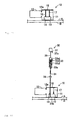
- Fig. 1 shows an auxiliary device for puncture needle 10 according to the embodiment.
- This auxiliary device for puncture needle 10 is comprised of: a plate-shape the auxiliary device main body 11; a plate-shape rotating-sliding contact part 12 rotatably connected to one of the edge parts of the auxiliary device main body 11, and a stabilization plate 13, which is a sideway U-shape in the plan view formed at the lower part of the auxiliary device main body 11, wherein, the auxiliary device main body 11 is formed in an approximately quadrangular shape with the length in the horizontal (right/left) direction being slightly longer than the length in the vertical (up/down) direction, on the centre lower part of which a rectangular window part 14, which is shorter in the vertical direction and longer in the horizontal direction than the auxiliary device main body 11, is formed.
- a pair of guide grooves 16,17 which are extending from the projecting edge part 15 to the upper end part of the window part 14 in the vertical (up/down) direction, are formed from side to side keeping a certain distance, wherein the guide grooves 16 are comprised of wide grooves 16a located on the surface of the projecting edge part 15 and narrow grooves 16b extending from the lower end part of the wide grooves 16a to the upper end part of the window part 14, and the guide grooves 17 are comprised of wide grooves 17a located on the surface of the projecting edge part 15 and narrow grooves 17b extending from the lower end part of the wide grooves 17a to the upper end part of the window part 14.
- the back side portion (the bottom side portion of the concave part) of the wide grooves 16a is formed in the identical shape with the narrow grooves 16b (a semicircle-shape in the plan view), and the opening side portion of the wide grooves 16a is formed in an approximately fan-shape with the width becoming gradually wider toward the outside.
- the back side portion (the bottom side portion of the concave part) of the wide grooves 17a is formed in the identical shape with the narrow grooves 17b (a semicircle-shape in the plan view), and the opening side portion of the wide grooves 17a is formed in an approximately fan-shape with the width becoming gradually wider toward the outside.
- ribs 16c, 17c protruding toward the outside are formed at a portion corresponding to the narrow grooves 16b, 17b in the back surface of the auxiliary device main body 11.
- the rotating-sliding contact part 12 is formed in a rectangular-shape with the length in the horizontal (right/left) direction being approximately equal to the length in the horizontal direction of the auxiliary device main body 11, and the length in the vertical direction being approximately equal to the length between the lower end part of the projecting edge part 15 and the upper end of the window part 14 in the auxiliary device main body 11.
- This rotating-sliding contact part 12 is integrally formed with the auxiliary device main body 11 through the hinge connecting part 12a formed thin-walled, and rotates around the hinge connecting part 12a, allowing it to move forward/backward against the surface of the auxiliary device main body 11.
- the rotating-sliding contact part 12 is connected to the auxiliary device main body 11 in such a manner that the upper end edge part thereof is positioned slightly lower side than the lower end part of the projecting edge part 15, and that the lower end edge part thereof is positioned slightly lower side than the upper end part of the window part 14.
- ribs 12b, 12c extending to the right and left are formed on the back surface of the rotating-sliding contact part 12, keeping a certain distance in the vertical (up/down) direction.
- the stabilization plate 13 which is connected to the lower end part of the auxiliary device main body 11 with the sideway U-shape opening side portion facing the front, is formed integrally with the auxiliary device main body 11 by connecting the lower end part of the auxiliary device main body 11 to approximately centre in the cross direction of both the right and left side portions respectively. Consequently, as shown in Fig. 1(a), (d) , the guide grooves 16,17 formed at the auxiliary device main body 11 are positioned at the centre side of a sideway U-shape internal space of the stabilization plate 13 when viewed in the vertical (up/down) direction.
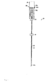
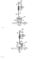
- the auxiliary device for puncture needle 10 constituted as the foregoing is used as an auxiliary device when the insertion-puncture needle 20 shown in Fig. 2 and the pullout-puncture needle 30 shown in Fig. 3 are used to puncture the patient's body.
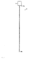
- the insertion-puncture needle 20 is comprised of an insertion-puncture needle-outer needle 21 shown in Fig. 4 and an insertion-puncture needle-inner needle 22 shown in Fig.
- the insertion-puncture needle-outer needle 21 is comprised of a stainless steel cylindrical body, inside of which an insertion hole 21a for inserting the insertion-puncture needle-inner needle 22 is formed, and the resin-made hub part 23 is attached to the base part (the upper end part) thereof.
- an upper part 23a is formed in a small cylindrical shape and a hub main body 23b is formed in a rectangular tubular shape from the centre to lower part side with the width becoming wider than that of the upper part 23a, wherein a guide hole 23c communicating to the insertion hole 21a is formed in the inside of the hub part 23.
- This guide hole 23c is formed in such a manner that the upper part side has a larger-diameter and the lower part side has a smaller-diameter, thereby the insertion-puncture needle-inner needle 22 can be inserted more easily from the upside of the hub part 23 and through the inside of the insertion hole 21a.
- a circular engaged part 23d having a vertical (up/down) pass through hole part is provided at one of the upper end parts on the peripheral surface of the hub main body 23b.
- a portion corresponding to the circular engaged part 23d in the tip part (lower end) of the insertion-puncture needle-outer needle 21 is cut off in an oblique direction, and is formed so that an opening 21b is visible from the transverse direction. More specifically, the opening 21b and the circular engaged part 23d are formed to face the same direction, and the facing direction of the opening 21b can be confirmed according to the position of the circular engaged part 23d.
- a plate-shape positioning part 24 is attached to the downside of the hub part 23 in the insertion-puncture needle-outer needle 21 spaced from the hub part 23.
- This positioning part 24 is attached to the insertion-puncture needle-outer needle 21 by inserting the insertion-puncture needle-outer needle 21 to the hole part formed at the centre part, and the attachment position thereof is arbitrarily setup in accordance with the projection amount (the sum of the length inserted to the suture part and the length in the vertical (up/down) direction of the auxiliary device for puncture needle 10) that is lower portion to the positioning part 24 of the insertion-puncture needle-outer needle 21,
- the insertion-puncture needle-inner needle 22 is comprised of a stainless steel thin rod insertable into the inside of the insertion hole 21a of the insertion-puncture needle-outer needle 21, and a resin-made hub part 25 is attached to the base part (the upper end part).
- This hub part 25 is formed in a square pole shape, at the lower part side of which the concave part (not shown) capable of accommodating the upper part 23a of the hub part 23 is formed.
- an engaging projection part 25a insertable into the inside of the hole part of the circular engaged part 23d is formed at one side in the peripheral surface lower end part of the hub part 25, and the lower end part of the engaging projection part 25a thereof is extending toward the downside.
- a portion corresponding to the engaging projection part 25a in the tip part (lower end) of the insertion-puncture needle-inner needle 22 is cut off in an oblique direction, and the facing direction of the cutting plane 22a can be confirmed according to the position of the engaging projection part 25a.
- the upper part 23a of the hub part 23 is automatically set into the inside of the hub part 25 as shown in Fig. 2 .
- the engaging projection part 25a is engaged with the circular engaged part 23d, and the cutting plane 22a of the insertion-puncture needle-inner needle 22 faces in the same direction as the opening 21b in the inside of the insertion hole 21a.
- a cylindrical shape protector 26 shown in Fig. 6 is attached thereto.
- This protector 26 comprised of a cylindrical body protects the puncture needle portion of the insertion-puncture needle 20 by engaging the lower end portion of the hub part 23 to the peripheral part of the opening, with the puncture needle portion of the insertion-puncture needle 20 being accommodated inside therein.
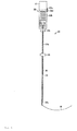
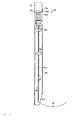
- the pullout-puncture needle 30 is comprised of the pullout-puncture needle-outer needle 31 shown in Fig. 7 and the pullout-puncture needle-inner needle 32 shown in Fig. 8 , wherein the pullout-puncture needle-outer needle 31 is comprised of a stainless steel cylindrical body, inside of which an insertion hole 31a for inserting the pullout-puncture needle-inner needle 32 is formed, and the resin-made hub part 33 is attached to the base part (the upper end part) thereof.
- an upper part 33a is formed in a small cylindrical shape and a hub main body 33b is formed in a rectangular tubular shape from the centre to lower part side with the width becoming wider than that of the upper part 33a, wherein a guide hole 33c communicating to the insertion hole 31a is formed in the inside of the hub part 33.
- This guide hole 33c is formed in such a manner that the upper part side has a larger-diameter and the lower part side has a smaller-diameter, thereby the pullout-puncture needle-inner needle 32 can be inserted more easily from the upside of the hub part 33 and through the inside of the insertion hole 31a.
- a circular engaged part 23d having a vertical pass through hole part is provided at one of the upper end parts on the peripheral surface of the hub main body 33b.
- a portion corresponding to a circular engaged part 33d in the tip part (lower end) of the pullout-puncture needle-outer needle 31 is cut off in an oblique direction, and is formed so that an opening 31b is visible from the transverse direction. More specifically, the opening 31b and the circular engaged part 33d are formed to face the same direction, and the facing direction of the opening 31b can be confirmed according to the position of the circular engaged part 33d.
- a plate-shape positioning part 34 is attached to the downside of the hub part 33 in the pullout-puncture needle-outer needle 31, spaced from the hub part 33.
- This positioning part 34 is attached to the pullout-puncture needle-outer needle 31 by inserting the pullout-puncture needle-outer needle 31 to the hole part formed at the centre part, the attachment position thereof is arbitrarily setup in accordance with the projection amount (the sum of the length inserted to the suture part and the length in the vertical (up/down) direction of the auxiliary device for puncture needle 10) that is lower portion to the positioning part 34 of the pullout-puncture needle-outer needle 31,
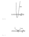
- the pullout-puncture needle-inner needle 32 is comprised of: a thin stainless steel inner needle 35 now insertable into the inside of the insertion hole 31a of the pullout-puncture needle-outer needle 31; a circular capture part 36 provided at the tip part of the inner needle 35, and a hub part 37 provided at the upper end part of the inner needle 35.
- the capture part 36 is comprised of a very fine linear object thinner than the inner needle 35, and is bent from the tip part of the inner needle 35 extending in an approximately horizontal direction.
- This capture part 36 is in an approximately round shape in the plane view as shown in Fig. 9 , and is in a circular arc shape in the side view with the centre portion being curved downward.
- a small U-shaped engaging curve part 36a is formed at the tip part of the capture part 36.
- This capture part 36 is flexible and can be easily deformed into a straight line by applying a slight force so as to move away from the tip part of the engaging curve part 36a, and at the same time, the shape can be easily restored to the original circular shape by releasing the force.
- a concave part (not shown) capable of accommodating the upper part 33a of the hub part 33 is formed at the lower part side portion of the hub part 37.
- an engaging projection part 37a insertable into the inside of the hole part of the circular engaged part 33d is formed at a portion corresponding to the extending direction of the capture part 36 in the peripheral surface lower end part of the hub part 37, and the lower end part of the engaging projection part 37a is extending downward.
- the upper part 33a of the hub part 33 is automatically set into the inside of the hub part 35 as shown in Fig. 3 .
- the engaging projection part 37a is engaged with the circular engaged part 33d, and the capture part 36 is protruded from the opening 31b of the pullout-puncture needle-outer needle 31 to the outside, returning to the circular shape.
- an approximately cylindrical shape protector 36 shown in Fig. 10 is attached thereto.
- This protector 38 is comprised of a tubular object, one side portion of the peripheral surface tip part of which is cut off obliquely so as to be opened together with the tip part, and the lower end portion of the hub part 33 is engaged to the peripheral part of the opening with the puncture needle portion of the pullout-puncture needle 30 being accommodated inside, thereby the puncture needle portion of the pullout-puncture needle 30 is protected.
- the aforementioned auxiliary device for puncture needle 10, the insertion-puncture needle 20 and the pullout-puncture needle 30 are used to describe a case, for example, the case in which the abdominal wall A as the skin portion of this invention and the gastric wall B as the organ wall part of this invention (see Fig. 11 or Fig. 22 ) in a patient are sutured.
- the auxiliary device for puncture needle 10 as shown in Fig. 11 is installed on the skin surface of the abdominal wall A in the patient.
- the capture part 36 is accommodated inside of the pullout-puncture needle-outer needle 31, the tip side portion of the pullout-puncture needle 30 with the hub part 37 positioned at the upside of the hub part 33 of the pullout-puncture needle-outer needle 31 is inserted into the inside of the guide grooves 16 of the auxiliary device for puncture needle 10 as shown in Fig. 12 .
- the auxiliary device for puncture needle 10 the rotating-sliding contact part 12 is rotated to the surface side of the auxiliary device main body 11, and as shown in Fig. 13 , the rotating-sliding contact part 12 is placed over the surface of the auxiliary device main body 11, and then the pullout-puncture needle 30 is pushed into the skin surface in the patient's abdominal region, and as shown in Fig. 14 , the pullout-puncture needle 30 is pierced into the abdominal wall A and the gastric wall B.
- the rotating-sliding contact part 12 is pushed toward the auxiliary device main body 11 with fingers, thereby the pullout-puncture needle 30 is lowered while slidingly contacting the guide grooves 16 and the rotating-sliding contact part 12, with it being prevented from disengaging from the guide grooves 16 by the rotating-sliding contact part 12. Moreover, at that time, the puncturing state of the pullout-puncture needle 30 can be confirmed from the window part 14.
- the pullout-puncture needle 30 is pierced until the positioning part 34 runs into the upper end part of the auxiliary device for puncture needle 10 so that the opening 31b of the pullout-puncture needle-outer needle 31 is positioned at the inside of the gastric wall B.
- the pullout-puncture needle-inner needle 32 is further inserted inside the pullout-puncture needle-outer needle 31, and as shown in Fig. 15 , and allow the capture part 36 to protrude from the opening 31b of the pullout-puncture needle-outer needle 31.
- the capture part 36 is spread to form a circular shape so as to be an approximately right angle to the pullout-puncture needle-outer needle 31 at the inside of the gastric wall B.
- the direction to which this capture part 36 spreads can be confirmed from the positions of the engaging projection part 37a and the circular engaged part 33d.
- the insertion-puncture needle 20 is pulled out from the insertion-puncture needle-inner needle 22, and the tip side portion of the insertion-puncture needle-outer needle 21 is inserted in between the guide grooves 17 of the auxiliary device for puncture needle 10 and the rotating-sliding contact part 12 as shown in Fig. 16 .
- the upper end part of the guide grooves 17 is comprised of the wide grooves 17a, the wide which is wider at the open side, allowing the insertion-puncture needle-outer needle 21 to be attached easier.
- the tip side portion of the insertion-puncture needle-outer needle 21 may be installed inside the guide grooves 17, and thereafter, the rotating-sliding contact part 12 may be rotated to the surface side of the auxiliary device main body 11 as well.
- the insertion-puncture needle-outer needle 21 is pushed into the skin surface in the patient's abdominal region, and then pierced into the abdominal wall A and the gastric wall B.
- the insertion-puncture needle-outer needle 21 is pierced until the positioning part 24 runs into the upper end part of the auxiliary device for puncture needle 10, thereby the tip part of the insertion-puncture needle-outer needle 21 is positioned the centre neighborhood of the capture part 36.
- the circular engaged part 23d is made to face with the engaging projection part 37a and the circular engaged part 33d.
- the opening 21b of the insertion-puncture needle-outer needle 21 is faced with the opening 31b of the pullout-puncture needle-outer needle 31.
- a surgical suture 28 is inserted from the guide hole of the hub part 23 into the inside of the insertion hole 21a, and allow the tip part thereof to protrude from the opening 21b of the insertion-puncture needle-outer needle 21 ad shown in Fig. 19 .
- the tip portion of the surgical suture 28 is positioned inside the capture part 36 by arbitrarily manipulating the insertion-puncture needle-outer needle 21 or the tip part of the pullout-puncture needle 30 .
- the hub part 37 is pulled upward to move the pullout-puncture needle-inner needle 32 to the upper part side of the pullout-puncture needle-outer needle 31.
- both end side portions of the surgical suture 28 are tied, thereby the suturing process is finished.
- the surgical suture 28 when inserting the surgical suture 28 into the inside of the insertion hole 21a of the insertion-puncture needle-outer needle 21, in the event that the surgical suture 28 gets stuck inside the insertion hole 21a, the surgical suture 28 can be pulled out from the insertion-puncture needle-outer needle 21 once, and the insertion-puncture needle-inner needle 22 can be inserted inside the insertion hole 21a to remove the suture stuck inside the insertion hole 21a, and then, the surgical suture 28 is inserted again into the inside of the insertion hole 21a to allow the tip side portion of the surgical suture 28 to protrude from the opening 21b.
- this auxiliary device for puncture needle 10 when the pullout-puncture needle 30 is used to puncture the patient's body with the tip portion of the puncture needle installed at the guide grooves 16 of the auxiliary device for puncture needle placed on the sutured part of the patient's body, the rotating-sliding contact part 12 is rotated to the surface side of the auxiliary device main body 11, thereby the pullout-puncture needle 30 can be prevented from disengaging from the guide grooves 16. And, the pullout-puncture needle 30 in the foregoing state is pushed toward the patient's body, thereby the tip part of the pullout-puncture needle 30 can make a puncture in the patient's body. In this case, since the pullout-puncture needle 30 moves along the guide grooves 16, the needle can puncture into the body in the appropriate state without displacement.
- the tip side portion of the insertion-puncture needle 20 is inserted into the inside of the guide grooves 17 from the upper part side of the auxiliary device for puncture needle 10.
- the tip side portion of the insertion-puncture needle-outer needle 21 is installed at the guide grooves 17, and the rotating-sliding contact part 12 is again rotated to the surface side of the auxiliary device main body 11, thereby the insertion-puncture needle-outer needle 21 can be prevented from disengaging from the guide grooves 17.
- the insertion-puncture needle-outer needle 21 in the foregoing state is pushed toward inside the patient's body, thereby a puncture can be made in the patient's body.
- the insertion-puncture needle-outer needle 30 moves along the guide grooves 17, the needle can puncture into the body in the appropriate state without displacement.
- the auxiliary device for puncture needle 10 can be removed to move the pullout-puncture needle 30 or the tip portion of the insertion-puncture needle-outer needle 21, so that the positional relationship one another can be adjusted so as to be in the positional relationship in which the surgical suture 28 and the capture part 36 are easily engaged.
- the auxiliary device main body 11 and the rotating-sliding contact part 12 are formed in a plate-shape, and the guide grooves 16, 17 are formed from the upper end of the auxiliary device main body 11 to the upper end of the window part 14, thereby the auxiliary device main body 11 and the rotating-sliding contact part 12 can be easily grasped, making the manipulation easier.
- the length of the guide grooves 16,17 are formed longer in the vertical (up/down) direction, and thereby the puncture operation is stabilized when making punctures using the pullout-puncture needle 30 and the insertion-puncture needle-outer needle 21.
- the stabilization plate 13 was provided at the lower part of the auxiliary device main body 11, thereby the skin surface and the guide grooves 16, 17 are perpendicularly intersected with one another when placing the stabilization plate 13 to the skin surface of the patient during the installation of the auxiliary device for puncture needle 10 in the patient's body. Consequently, the pullout-puncture needle 30 and the insertion-puncture needle-outer needle 21 can puncture the abdominal wall A and the gastric wall B of the patient at an appropriate angle.
- the projecting edge part 15 was formed at the upper end part of the auxiliary device main body 11, and the wide grooves 16a, 17a were formed at the projecting edge part 15, thereby the projecting edge part 15 can act as a reinforcing part, enhancing the strength of the auxiliary device for puncture needle 10.
- the opening side portion width of the wide grooves 16a, 17a is wider, thereby the pullout-puncture needle 30 and the insertion-puncture needle-outer needle 21 can be attached to the guide grooves 16,17 more easily.
- the rotating-sliding contact part 12 being positioned to the surface side of the auxiliary device main body 11, the operation to insert the pullout-puncture needle 30 and the tip side portion of the insertion-puncture needle-outer needle 21 in between the guide grooves 17 of the auxiliary device for puncture needle 10 and the rotating-sliding contact part 12 is easier.
- the window part 14 is provided at the lower part the auxiliary device main body 11, thereby the manipulation can be done while observing the pullout-puncture needle 30 passing through inside the auxiliary device for puncture needle 10 and the insertion-puncture needle-outer needle 21, allowing the operation to be more secure.
- the auxiliary device for puncture needle according to the present invention is not limited to the aforementioned embodiment, and may be optionally modified and implemented accordingly within the scope of the invention.
- the auxiliary device main body 11 is formed in a thin plate body, this auxiliary device main body may also be constituted using a thick plate body, through the use of which the stabilization plate 13 and the projecting edge part 15 may be omitted.
- the window part 14 provided at the auxiliary device for puncture needle 10 may also be omitted.
- the puncture needles can be manipulated while observing the pullout-puncture needle 30 protruding out of the lower end part of the rotating-sliding contact part 12 and the tip portion of the insertion-puncture needle-outer needle 21.
- the length of the rotating-sliding contact part 12 in the vertical (up/down) direction may also be extended to arrange the window part at the lower part of the rotating-sliding contact part.
- auxiliary device main body 11 Although only a pair of guide grooves 16, 17 are formed on the auxiliary device main body 11, 3 or more of these guide grooves may also be formed. This allows, the distance between the pullout-puncture needle 30 and the insertion-puncture needle-outer needle 21 to be changed. Moreover, this allows 3 or more puncture needles to be used also.
- the uses of the auxiliary device for puncture needle according to the present invention are not limited to the pullout-puncture needle 30 and the insertion-puncture needle 20 for suturing the abdominal wall A and the gastric wall B, but it may also be used as other puncture needles employed in suturing the other sites in the body.
Abstract
Description
- The present invention relates to an auxiliary device for puncture needle used when plural puncture needles employed in suturing the sutured part consisting of an organ and the skin portion in a patient's body are used to puncture a patient's body.
- Traditionally, medical suturing devices comprising plural puncture needles have been used to suture and secure the sutured part in a patient's body, particularly the sutured part consisting of an organ and the skin portion. For example, the intragastrical administrations of fluid diet and/or liquid nutritional supplements using a gastrostomy tube to persons who are unable to take food from mouth by their own due to functional decline in old age and/or diseases have been practiced, wherein the gastrostomy tube is attached to a hole part formed in the patient's abdominal region. In the foregoing case, in order to correctly attach the gastrostomy tube to the patient, a method for preliminarily securing the abdominal wall A and the gastric wall using a medical suturing device has also been practiced (for example, see Patent Literature 1).
- This medical suturing device comprises 2 puncture needles installed in parallel, spaced with the use of a connecting plate having a pair of connecting holes and an insertion length adjusting plate having a pair of interdigitation holes, and prior to performing the suture, these 2 puncture needles are used to simultaneously puncture into the sutured part of the patient. Next, while one of puncture needles is threaded with surgical suture, the other puncture needle is threaded with an inner needle to which a loop body consisting of a wire at the tip part is connected, and then the inner needle is pulled out from the puncture needle with the surgical suture grabbed by the loop body in the patient's body. And, after pulling out the 2 puncture needles from the patient, both side portions of the surgical suture protruding outside the patient's body are tied up to complete the suturing process. Moreover, the tip part of the puncture needle into which the inner needle is inserted, is formed in curvature with the tip opening facing transversely, so that the loop body protrudes toward the outside while extending in the transverse direction when the inner needle is pushed into the inside of the puncture needle so as to be able to grab the surgical suture.
[Patent Literature 1] Unexamined Patent Publication S05-161655 - However, in the conventional medical suturing device, because of 2 puncture needles being fixed to the connecting plate and the insertion length adjusting plate at the time of making a puncture, there exists a problem that if 2 puncture needles are not appropriately positioned one another, the positional relationship cannot be corrected in midstream. Consequently, there is a difficulty in manipulating the puncture needles at the time of making a puncture.
- The present invention is made in an effort to address the foregoing problems, and the purpose is to provide an auxiliary device for puncture needle capable of improving the suture stability while making the manipulation of the puncture needle easier.
- To achieve the aforementioned purpose, an auxiliary device for puncture needle according to the present invention, which is used when plural puncture needles employed in securing an organ to the skin portion with surgical suture are used to puncture the skin portion through to the organ, is constitutionally characterised by comprising an auxiliary device main body, on the surface of which plural parallel guide grooves are formed so as to be able to install the plural puncture needles movable in the axial direction, and a rotating-sliding contact part slidingly contacting to the peripheral surface of the puncture needles installed in the guide grooves by being rotatably attached to one of the edges approximately parallel to the extending direction of the guide grooves in the auxiliary device main body and by rotating to the surface side of the auxiliary device main body.
- In accordance with the auxiliary device for puncture needle according to the present invention constituted as the foregoing, when the puncture needles are used to puncture in a patient's body with the tip portion of the puncture needles positioned at the guide grooves of the auxiliary device placed on the sutured part in the patient's body, and the rotating-sliding contact part is rotated to the surface side of the auxiliary device main body, thereby the puncture needles are prevented from disengaging from the guide grooves of the auxiliary device main body. And, the puncture needles in the foregoing state are pushed against the patient's body; thereby the tip parts of the puncture needles can make punctures in the patient's body. In this case, since the puncture needles move along the guide grooves, the needles can puncture into the body in the appropriate state without displacement.
- Moreover, in the event that another puncture needle is used to puncture in the patient's body in parallel to the puncture needle already-punctured into the body, the another puncture needle can be installed in the another guide groove with the rotating-sliding contact part being separated from the surface of the auxiliary device main body once, and then the rotating-sliding contact part is again rotated to the surface side of the auxiliary device main body, thereby both the puncture needles can be positioned in the guide grooves of the auxiliary device main body. Thereby, both the puncture needles can be prevented from disengaging from the guide grooves. Moreover, with the rotating-sliding contact part remain positioned at the surface side of the auxiliary device main body; the other puncture needle may also be inserted from the upside of the auxiliary device for puncture needle. And, the other puncture needle is pushed against the patient's body; thereby the tip part of the other puncture needle can make a puncture in the patient's body.
- In this case, since the other puncture needle also moves along the guide groove, the needle can puncture into the body in the appropriate state without displacement. Moreover, in the event that the positional relationship between the already-punctured puncture needle and the other puncture needle is not appropriate, the puncture auxiliary device can be removed from both the puncture needles to move one of or both the tip parts of the puncture needles so that the positional relationship one another may be adjusted so as to be in the positional relationship in which the surgical suture and the loop body grasping the surgical suture can be easily engaged. As the foregoing, in accordance with the auxiliary device for puncture needle according to the present invention, the puncture operation of the puncture needles can be performed more easily, and at the same time the positional relationships of the plural puncture needles can also be adjusted during the puncture operation.
- Another constitutional characteristic of the auxiliary device for puncture needle according to the present invention is at least the auxiliary device main body out of the auxiliary device main body and the rotating-sliding contact part is formed in a plate-shape, and the guide grooves are formed from one end to the other end of the auxiliary device main body. This allows at least the auxiliary device main body to be easily grasped and the auxiliary device for puncture needle to be manipulated more easily, and at the same time, this further allows the guide grooves to be lengthened, stabilizing the puncture operation when making the puncture.
- And another constitutional characteristic of the auxiliary device for puncture needle according to the present invention is that a stabilization plate, the bottom surface of which is formed at a plane perpendicularly intersecting with the extending direction of the plural guide grooves is provided at a portion placed to the skin portion side in the auxiliary device main body. This allows the skin surface and the guide grooves of the auxiliary device for puncture needle to perpendicularly intersect with one another when the stabilization plate is placed to the patient's skin surface during the installation of the auxiliary device for puncture needle in the patient's body, so that the puncture needles can make punctures in the patient's skin portion at an appropriate angle.
- And another constitutional characteristic of the auxiliary device for puncture needle according to the present invention is that the projecting edge part protruding toward the surface side is formed at a portion opposite to the portion placed at the skin portion in the auxiliary device main body so that the rotating-sliding contact part is positioned inside the projecting edge part when being rotated to the surface side of the auxiliary device main body, and at the same time, the opening side width of the portion constituting the guide grooves in the projecting edge part is larger than the width of the other portion of the guide grooves. This allows the projecting edge part to be a reinforcing part, enhancing the strength of the auxiliary device for puncture needle. Moreover, the opening side width of the portion located on the projecting edge part in the guide grooves is made larger, making the attachment of the puncture needles to the guide grooves easier.
- And another constitutional characteristic of the auxiliary device for puncture needle according to the present invention is that the confirmation window part for confirming the puncture needle placement is provided at the portion placed to the skin portion side of at least either one of the auxiliary device main body and the rotating-sliding contact part. This allows the puncture operation to be performed while observing the puncture needles passing through the inside of the auxiliary device for puncture needle, making the operation more secure.
- Hereinafter, one embodiment of this invention will be descried with reference to drawings.
Fig. 1 shows an auxiliary device forpuncture needle 10 according to the embodiment. This auxiliary device forpuncture needle 10 is comprised of: a plate-shape the auxiliary devicemain body 11; a plate-shape rotating-slidingcontact part 12 rotatably connected to one of the edge parts of the auxiliary devicemain body 11, and astabilization plate 13, which is a sideway U-shape in the plan view formed at the lower part of the auxiliary devicemain body 11, wherein, the auxiliary devicemain body 11 is formed in an approximately quadrangular shape with the length in the horizontal (right/left) direction being slightly longer than the length in the vertical (up/down) direction, on the centre lower part of which arectangular window part 14, which is shorter in the vertical direction and longer in the horizontal direction than the auxiliary devicemain body 11, is formed. - Moreover, on the upper end part of the auxiliary device
main body 11, as shown inFig. 1(a) , a spindle-shaped projectingedge part 15 with the width becoming wider in the centre side portion and narrower toward both ends in the plan view, is formed. And, on the surface of the auxiliary devicemain body 11, as shown inFig. 1(b) , a pair ofguide grooves edge part 15 to the upper end part of thewindow part 14 in the vertical (up/down) direction, are formed from side to side keeping a certain distance, wherein theguide grooves 16 are comprised ofwide grooves 16a located on the surface of the projectingedge part 15 andnarrow grooves 16b extending from the lower end part of thewide grooves 16a to the upper end part of thewindow part 14, and theguide grooves 17 are comprised ofwide grooves 17a located on the surface of theprojecting edge part 15 andnarrow grooves 17b extending from the lower end part of thewide grooves 17a to the upper end part of thewindow part 14. - And, as shown in
Fig. 1 (d) , the back side portion (the bottom side portion of the concave part) of thewide grooves 16a is formed in the identical shape with thenarrow grooves 16b (a semicircle-shape in the plan view), and the opening side portion of thewide grooves 16a is formed in an approximately fan-shape with the width becoming gradually wider toward the outside. Similarly, the back side portion (the bottom side portion of the concave part) of thewide grooves 17a is formed in the identical shape with thenarrow grooves 17b (a semicircle-shape in the plan view), and the opening side portion of thewide grooves 17a is formed in an approximately fan-shape with the width becoming gradually wider toward the outside. Moreover, as shown inFig. 1 (e) ,ribs narrow grooves main body 11. - The rotating-sliding
contact part 12 is formed in a rectangular-shape with the length in the horizontal (right/left) direction being approximately equal to the length in the horizontal direction of the auxiliary devicemain body 11, and the length in the vertical direction being approximately equal to the length between the lower end part of the projectingedge part 15 and the upper end of thewindow part 14 in the auxiliary devicemain body 11. This rotating-slidingcontact part 12 is integrally formed with the auxiliary devicemain body 11 through thehinge connecting part 12a formed thin-walled, and rotates around thehinge connecting part 12a, allowing it to move forward/backward against the surface of the auxiliary devicemain body 11. Moreover, the rotating-slidingcontact part 12 is connected to the auxiliary devicemain body 11 in such a manner that the upper end edge part thereof is positioned slightly lower side than the lower end part of the projectingedge part 15, and that the lower end edge part thereof is positioned slightly lower side than the upper end part of thewindow part 14. And,ribs contact part 12, keeping a certain distance in the vertical (up/down) direction. - The
stabilization plate 13, which is connected to the lower end part of the auxiliary devicemain body 11 with the sideway U-shape opening side portion facing the front, is formed integrally with the auxiliary devicemain body 11 by connecting the lower end part of the auxiliary devicemain body 11 to approximately centre in the cross direction of both the right and left side portions respectively. Consequently, as shown inFig. 1(a), (d) , theguide grooves main body 11 are positioned at the centre side of a sideway U-shape internal space of thestabilization plate 13 when viewed in the vertical (up/down) direction. - The auxiliary device for
puncture needle 10 constituted as the foregoing is used as an auxiliary device when the insertion-puncture needle 20 shown inFig. 2 and the pullout-puncture needle 30 shown inFig. 3 are used to puncture the patient's body. The insertion-puncture needle 20 is comprised of an insertion-puncture needle-outer needle 21 shown inFig. 4 and an insertion-puncture needle-inner needle 22 shown inFig. 5 , wherein the insertion-puncture needle-outer needle 21 is comprised of a stainless steel cylindrical body, inside of which aninsertion hole 21a for inserting the insertion-puncture needle-inner needle 22 is formed, and the resin-madehub part 23 is attached to the base part (the upper end part) thereof. On thishub part 23, anupper part 23a is formed in a small cylindrical shape and a hubmain body 23b is formed in a rectangular tubular shape from the centre to lower part side with the width becoming wider than that of theupper part 23a, wherein aguide hole 23c communicating to theinsertion hole 21a is formed in the inside of thehub part 23. - This
guide hole 23c is formed in such a manner that the upper part side has a larger-diameter and the lower part side has a smaller-diameter, thereby the insertion-puncture needle-inner needle 22 can be inserted more easily from the upside of thehub part 23 and through the inside of theinsertion hole 21a. Moreover, a circular engagedpart 23d having a vertical (up/down) pass through hole part is provided at one of the upper end parts on the peripheral surface of the hubmain body 23b. And, a portion corresponding to the circular engagedpart 23d in the tip part (lower end) of the insertion-puncture needle-outer needle 21 is cut off in an oblique direction, and is formed so that an opening 21b is visible from the transverse direction. More specifically, the opening 21b and the circular engagedpart 23d are formed to face the same direction, and the facing direction of the opening 21b can be confirmed according to the position of the circular engagedpart 23d. - And a plate-
shape positioning part 24 is attached to the downside of thehub part 23 in the insertion-puncture needle-outer needle 21 spaced from thehub part 23. Thispositioning part 24 is attached to the insertion-puncture needle-outer needle 21 by inserting the insertion-puncture needle-outer needle 21 to the hole part formed at the centre part, and the attachment position thereof is arbitrarily setup in accordance with the projection amount (the sum of the length inserted to the suture part and the length in the vertical (up/down) direction of the auxiliary device for puncture needle 10) that is lower portion to the positioningpart 24 of the insertion-puncture needle-outer needle 21, - wherein the insertion-puncture needle-
inner needle 22 is comprised of a stainless steel thin rod insertable into the inside of theinsertion hole 21a of the insertion-puncture needle-outer needle 21, and a resin-madehub part 25 is attached to the base part (the upper end part). Thishub part 25 is formed in a square pole shape, at the lower part side of which the concave part (not shown) capable of accommodating theupper part 23a of thehub part 23 is formed. Moreover, anengaging projection part 25a insertable into the inside of the hole part of the circular engagedpart 23d is formed at one side in the peripheral surface lower end part of thehub part 25, and the lower end part of theengaging projection part 25a thereof is extending toward the downside. And, a portion corresponding to theengaging projection part 25a in the tip part (lower end) of the insertion-puncture needle-inner needle 22 is cut off in an oblique direction, and the facing direction of thecutting plane 22a can be confirmed according to the position of theengaging projection part 25a. - Consequently, as the insertion-puncture needle-
inner needle 22 is inserted into the inside of theinsertion hole 21a of the insertion-puncture needle-outer needle 21, theupper part 23a of thehub part 23 is automatically set into the inside of thehub part 25 as shown inFig. 2 . At this time, theengaging projection part 25a is engaged with the circular engagedpart 23d, and thecutting plane 22a of the insertion-puncture needle-inner needle 22 faces in the same direction as the opening 21b in the inside of theinsertion hole 21a. Moreover, whenever the insertion-puncture needle 20 constituted by assembling the insertion-puncture needle-inner needle 22 to the insertion-puncture needle-outer needle 21 is not in use, acylindrical shape protector 26 shown inFig. 6 is attached thereto. Thisprotector 26 comprised of a cylindrical body protects the puncture needle portion of the insertion-puncture needle 20 by engaging the lower end portion of thehub part 23 to the peripheral part of the opening, with the puncture needle portion of the insertion-puncture needle 20 being accommodated inside therein. - The pullout-
puncture needle 30 is comprised of the pullout-puncture needle-outer needle 31 shown inFig. 7 and the pullout-puncture needle-inner needle 32 shown inFig. 8 , wherein the pullout-puncture needle-outer needle 31 is comprised of a stainless steel cylindrical body, inside of which aninsertion hole 31a for inserting the pullout-puncture needle-inner needle 32 is formed, and the resin-madehub part 33 is attached to the base part (the upper end part) thereof. On thishub part 33, anupper part 33a is formed in a small cylindrical shape and a hubmain body 33b is formed in a rectangular tubular shape from the centre to lower part side with the width becoming wider than that of theupper part 33a, wherein aguide hole 33c communicating to theinsertion hole 31a is formed in the inside of thehub part 33. - This
guide hole 33c is formed in such a manner that the upper part side has a larger-diameter and the lower part side has a smaller-diameter, thereby the pullout-puncture needle-inner needle 32 can be inserted more easily from the upside of thehub part 33 and through the inside of theinsertion hole 31a. Moreover, a circularengaged part 23d having a vertical pass through hole part is provided at one of the upper end parts on the peripheral surface of the hubmain body 33b. And, a portion corresponding to a circularengaged part 33d in the tip part (lower end) of the pullout-puncture needle-outer needle 31 is cut off in an oblique direction, and is formed so that anopening 31b is visible from the transverse direction. More specifically, theopening 31b and the circular engagedpart 33d are formed to face the same direction, and the facing direction of theopening 31b can be confirmed according to the position of the circular engagedpart 33d. - And a plate-
shape positioning part 34 is attached to the downside of thehub part 33 in the pullout-puncture needle-outer needle 31, spaced from thehub part 33. Thispositioning part 34 is attached to the pullout-puncture needle-outer needle 31 by inserting the pullout-puncture needle-outer needle 31 to the hole part formed at the centre part, the attachment position thereof is arbitrarily setup in accordance with the projection amount (the sum of the length inserted to the suture part and the length in the vertical (up/down) direction of the auxiliary device for puncture needle 10) that is lower portion to thepositioning part 34 of the pullout-puncture needle-outer needle 31, - The pullout-puncture needle-
inner needle 32 is comprised of: a thin stainless steelinner needle 35 now insertable into the inside of theinsertion hole 31a of the pullout-puncture needle-outer needle 31; acircular capture part 36 provided at the tip part of theinner needle 35, and ahub part 37 provided at the upper end part of theinner needle 35. Thecapture part 36 is comprised of a very fine linear object thinner than theinner needle 35, and is bent from the tip part of theinner needle 35 extending in an approximately horizontal direction. Thiscapture part 36 is in an approximately round shape in the plane view as shown inFig. 9 , and is in a circular arc shape in the side view with the centre portion being curved downward. And, a small U-shapedengaging curve part 36a is formed at the tip part of thecapture part 36. - This
capture part 36 is flexible and can be easily deformed into a straight line by applying a slight force so as to move away from the tip part of the engagingcurve part 36a, and at the same time, the shape can be easily restored to the original circular shape by releasing the force. Moreover, a concave part (not shown) capable of accommodating theupper part 33a of thehub part 33 is formed at the lower part side portion of thehub part 37. Moreover, an engagingprojection part 37a insertable into the inside of the hole part of the circular engagedpart 33d is formed at a portion corresponding to the extending direction of thecapture part 36 in the peripheral surface lower end part of thehub part 37, and the lower end part of the engagingprojection part 37a is extending downward. - Consequently, as the insertion-puncture needle-
inner needle 32 is inserted into the inside of theinsertion hole 31a of the insertion-puncture needle-outer needle 31 with thecapture part 36 being extended in a straight line, theupper part 33a of thehub part 33 is automatically set into the inside of thehub part 35 as shown inFig. 3 . In this case, the engagingprojection part 37a is engaged with the circular engagedpart 33d, and thecapture part 36 is protruded from theopening 31b of the pullout-puncture needle-outer needle 31 to the outside, returning to the circular shape. Moreover, whenever the pullout-puncture needle 30 constituted by assembling the pullout-puncture needle-inner needle 32 to the pullout-puncture needle-outer needle 31 is not in use, an approximatelycylindrical shape protector 36 shown inFig. 10 is attached thereto. - This
protector 38 is comprised of a tubular object, one side portion of the peripheral surface tip part of which is cut off obliquely so as to be opened together with the tip part, and the lower end portion of thehub part 33 is engaged to the peripheral part of the opening with the puncture needle portion of the pullout-puncture needle 30 being accommodated inside, thereby the puncture needle portion of the pullout-puncture needle 30 is protected. In this case, allow thecapture part 36 to protrude from the tip side of theprotector 38 so that no external force is applied to thecapture part 36. Thereby, the shape of thecapture part 36 can be maintained for a long-term. - Next, the aforementioned auxiliary device for
puncture needle 10, the insertion-puncture needle 20 and the pullout-puncture needle 30 are used to describe a case, for example, the case in which the abdominal wall A as the skin portion of this invention and the gastric wall B as the organ wall part of this invention (seeFig. 11 orFig. 22 ) in a patient are sutured. In this suture, firstly, the auxiliary device forpuncture needle 10 as shown inFig. 11 is installed on the skin surface of the abdominal wall A in the patient. After that, thecapture part 36 is accommodated inside of the pullout-puncture needle-outer needle 31, the tip side portion of the pullout-puncture needle 30 with thehub part 37 positioned at the upside of thehub part 33 of the pullout-puncture needle-outer needle 31 is inserted into the inside of theguide grooves 16 of the auxiliary device forpuncture needle 10 as shown inFig. 12 . - Next, the auxiliary device for
puncture needle 10 ?the rotating-slidingcontact part 12 is rotated to the surface side of the auxiliary devicemain body 11, and as shown inFig. 13 , the rotating-slidingcontact part 12 is placed over the surface of the auxiliary devicemain body 11, and then the pullout-puncture needle 30 is pushed into the skin surface in the patient's abdominal region, and as shown inFig. 14 , the pullout-puncture needle 30 is pierced into the abdominal wall A and the gastric wall B. In this case, the rotating-slidingcontact part 12 is pushed toward the auxiliary devicemain body 11 with fingers, thereby the pullout-puncture needle 30 is lowered while slidingly contacting theguide grooves 16 and the rotating-slidingcontact part 12, with it being prevented from disengaging from theguide grooves 16 by the rotating-slidingcontact part 12. Moreover, at that time, the puncturing state of the pullout-puncture needle 30 can be confirmed from thewindow part 14. - In this case, the pullout-
puncture needle 30 is pierced until thepositioning part 34 runs into the upper end part of the auxiliary device forpuncture needle 10 so that theopening 31b of the pullout-puncture needle-outer needle 31 is positioned at the inside of the gastric wall B. After that, while the engagingprojection part 37a is being engaged to the circular engagedpart 33d, the pullout-puncture needle-inner needle 32 is further inserted inside the pullout-puncture needle-outer needle 31, and as shown inFig. 15 , and allow thecapture part 36 to protrude from theopening 31b of the pullout-puncture needle-outer needle 31. Thereby, thecapture part 36 is spread to form a circular shape so as to be an approximately right angle to the pullout-puncture needle-outer needle 31 at the inside of the gastric wall B. The direction to which thiscapture part 36 spreads can be confirmed from the positions of the engagingprojection part 37a and the circular engagedpart 33d. - Then, the insertion-
puncture needle 20 is pulled out from the insertion-puncture needle-inner needle 22, and the tip side portion of the insertion-puncture needle-outer needle 21 is inserted in between theguide grooves 17 of the auxiliary device forpuncture needle 10 and the rotating-slidingcontact part 12 as shown inFig. 16 . In this case, the upper end part of theguide grooves 17 is comprised of thewide grooves 17a, the wide which is wider at the open side, allowing the insertion-puncture needle-outer needle 21 to be attached easier. Moreover, in stead of these operations, with the rotating-slidingcontact part 12 being rotated once to expose the surface of the auxiliary devicemain body 11, the tip side portion of the insertion-puncture needle-outer needle 21 may be installed inside theguide grooves 17, and thereafter, the rotating-slidingcontact part 12 may be rotated to the surface side of the auxiliary devicemain body 11 as well. - After that, the insertion-puncture needle-
outer needle 21 is pushed into the skin surface in the patient's abdominal region, and then pierced into the abdominal wall A and the gastric wall B. In this case, as shown inFig. 17 , the insertion-puncture needle-outer needle 21 is pierced until thepositioning part 24 runs into the upper end part of the auxiliary device forpuncture needle 10, thereby the tip part of the insertion-puncture needle-outer needle 21 is positioned the centre neighborhood of thecapture part 36. At this time, the circular engagedpart 23d is made to face with the engagingprojection part 37a and the circular engagedpart 33d. Thereby, theopening 21b of the insertion-puncture needle-outer needle 21 is faced with theopening 31b of the pullout-puncture needle-outer needle 31. - Then, after removing the auxiliary device for
puncture needle 10 from the insertion-puncture needle-outer needle 21 and the pullout-puncture needle 30, as shown inFig. 18 , asurgical suture 28 is inserted from the guide hole of thehub part 23 into the inside of theinsertion hole 21a, and allow the tip part thereof to protrude from theopening 21b of the insertion-puncture needle-outer needle 21 ad shown inFig. 19 . In this case, while observing the tip portion of thesurgical suture 28 and thecapture part 36 with an endoscope, the tip portion of thesurgical suture 28 is positioned inside thecapture part 36 by arbitrarily manipulating the insertion-puncture needle-outer needle 21 or the tip part of the pullout-puncture needle 30 . Next, as shown inFig. 20 , thehub part 37 is pulled upward to move the pullout-puncture needle-inner needle 32 to the upper part side of the pullout-puncture needle-outer needle 31. - At this time, the tip portion of the
surgical suture 28 is engaged with thecapture part 36 trying to get inside the pullout-puncture needle-outer needle 31 together with thecapture part 36 and pushed against the edge part of theopening 31b. Thereby, the tip portion of thesurgical suture 28 is engaged to the edge part of theopening 31b. In the foregoing state, by pulling out the insertion-puncture needle-outer needle 21 and the pullout-puncture needle 30 from the patient's body, both the end side portions of thesurgical suture 28 pass completely through the gastric wall B and the abdominal wall A and protruded outside the patient's body, as shown inFig. 21 . - And, as shown in
Fig. 22 , both end side portions of thesurgical suture 28 are tied, thereby the suturing process is finished. Incidentally, when inserting thesurgical suture 28 into the inside of theinsertion hole 21a of the insertion-puncture needle-outer needle 21, in the event that thesurgical suture 28 gets stuck inside theinsertion hole 21a, thesurgical suture 28 can be pulled out from the insertion-puncture needle-outer needle 21 once, and the insertion-puncture needle-inner needle 22 can be inserted inside theinsertion hole 21a to remove the suture stuck inside theinsertion hole 21a, and then, thesurgical suture 28 is inserted again into the inside of theinsertion hole 21a to allow the tip side portion of thesurgical suture 28 to protrude from theopening 21b. - As described above, in this auxiliary device for
puncture needle 10, when the pullout-puncture needle 30 is used to puncture the patient's body with the tip portion of the puncture needle installed at theguide grooves 16 of the auxiliary device for puncture needle placed on the sutured part of the patient's body, the rotating-slidingcontact part 12 is rotated to the surface side of the auxiliary devicemain body 11, thereby the pullout-puncture needle 30 can be prevented from disengaging from theguide grooves 16. And, the pullout-puncture needle 30 in the foregoing state is pushed toward the patient's body, thereby the tip part of the pullout-puncture needle 30 can make a puncture in the patient's body. In this case, since the pullout-puncture needle 30 moves along theguide grooves 16, the needle can puncture into the body in the appropriate state without displacement. - Moreover, in the event that the insertion-puncture needle-
outer needle 21 is used to puncture the patient's body in parallel to the pullout-puncture needle 30, the tip side portion of the insertion-puncture needle 20 is inserted into the inside of theguide grooves 17 from the upper part side of the auxiliary device forpuncture needle 10. Or, with the rotating-slidingcontact part 12 being moved away once from the surface of the auxiliary devicemain body 11, the tip side portion of the insertion-puncture needle-outer needle 21 is installed at theguide grooves 17, and the rotating-slidingcontact part 12 is again rotated to the surface side of the auxiliary devicemain body 11, thereby the insertion-puncture needle-outer needle 21 can be prevented from disengaging from theguide grooves 17. And, the insertion-puncture needle-outer needle 21 in the foregoing state is pushed toward inside the patient's body, thereby a puncture can be made in the patient's body. In this case, since the insertion-puncture needle-outer needle 30 moves along theguide grooves 17, the needle can puncture into the body in the appropriate state without displacement. - Moreover, in the event that the positional relationship between the pullout-
puncture needle 30 and the insertion-puncture needle-outer needle 21 is not appropriate, the auxiliary device forpuncture needle 10 can be removed to move the pullout-puncture needle 30 or the tip portion of the insertion-puncture needle-outer needle 21, so that the positional relationship one another can be adjusted so as to be in the positional relationship in which thesurgical suture 28 and thecapture part 36 are easily engaged. In addition, the auxiliary devicemain body 11 and the rotating-slidingcontact part 12 are formed in a plate-shape, and theguide grooves main body 11 to the upper end of thewindow part 14, thereby the auxiliary devicemain body 11 and the rotating-slidingcontact part 12 can be easily grasped, making the manipulation easier. Moreover, the length of theguide grooves puncture needle 30 and the insertion-puncture needle-outer needle 21. - In addition, the
stabilization plate 13 was provided at the lower part of the auxiliary devicemain body 11, thereby the skin surface and theguide grooves stabilization plate 13 to the skin surface of the patient during the installation of the auxiliary device forpuncture needle 10 in the patient's body. Consequently, the pullout-puncture needle 30 and the insertion-puncture needle-outer needle 21 can puncture the abdominal wall A and the gastric wall B of the patient at an appropriate angle. Moreover, the projectingedge part 15 was formed at the upper end part of the auxiliary devicemain body 11, and thewide grooves edge part 15, thereby the projectingedge part 15 can act as a reinforcing part, enhancing the strength of the auxiliary device forpuncture needle 10. - In addition, the opening side portion width of the
wide grooves puncture needle 30 and the insertion-puncture needle-outer needle 21 can be attached to theguide grooves contact part 12 being positioned to the surface side of the auxiliary devicemain body 11, the operation to insert the pullout-puncture needle 30 and the tip side portion of the insertion-puncture needle-outer needle 21 in between theguide grooves 17 of the auxiliary device forpuncture needle 10 and the rotating-slidingcontact part 12 is easier. Moreover, thewindow part 14 is provided at the lower part the auxiliary devicemain body 11, thereby the manipulation can be done while observing the pullout-puncture needle 30 passing through inside the auxiliary device forpuncture needle 10 and the insertion-puncture needle-outer needle 21, allowing the operation to be more secure. - Moreover, the auxiliary device for puncture needle according to the present invention is not limited to the aforementioned embodiment, and may be optionally modified and implemented accordingly within the scope of the invention. For example, in the aforementioned embodiment, although the auxiliary device
main body 11 is formed in a thin plate body, this auxiliary device main body may also be constituted using a thick plate body, through the use of which thestabilization plate 13 and the projectingedge part 15 may be omitted. Moreover, thewindow part 14 provided at the auxiliary device forpuncture needle 10 may also be omitted. In this case, the puncture needles can be manipulated while observing the pullout-puncture needle 30 protruding out of the lower end part of the rotating-slidingcontact part 12 and the tip portion of the insertion-puncture needle-outer needle 21. Moreover, the length of the rotating-slidingcontact part 12 in the vertical (up/down) direction may also be extended to arrange the window part at the lower part of the rotating-sliding contact part. - In addition, in the aforementioned embodiment, although only a pair of
guide grooves main body 11, 3 or more of these guide grooves may also be formed. This allows, the distance between the pullout-puncture needle 30 and the insertion-puncture needle-outer needle 21 to be changed. Moreover, this allows 3 or more puncture needles to be used also. In addition, the uses of the auxiliary device for puncture needle according to the present invention are not limited to the pullout-puncture needle 30 and the insertion-puncture needle 20 for suturing the abdominal wall A and the gastric wall B, but it may also be used as other puncture needles employed in suturing the other sites in the body. -
- [
Fig. 1 ] shows the auxiliary device for puncture needle according to one embodiment of the present invention, in which (a) is a plane view, (b) is a front view, (c) is a side view, (d) is a bottom view and (e) is a rear view. - [
Fig. 2 ] is a front view showing an insertion-puncture needle. - [
Fig. 3 ] is a front view showing a pullout-puncture needle. [Fig. 4 ] is a front view showing an insertion-puncture needle-outer needle. - [
Fig. 5 ] is a frond view showing an insertion-puncture needle-inner needle. - [
Fig. 6 ] is a front view showing an insertion-puncture needle to which a protector is attached. - [
Fig. 7 ] is a frond view showing a pullout-puncture needle-outer needle. - [
Fig. 8 ] is a front view showing a pullout-puncture needle-inner needle. - [
Fig. 9 ] is a plane view showing a capture part. - [
Fig. 10 ] is a front view showing a pullout-puncture needle to which a protector is attached. - [
Fig. 11 ] is an illustration showing an auxiliary device for puncture needle installed in an abdominal region. - [
Fig. 12 ] is an illustration showing an auxiliary device for puncture needle, to the guide grooves of which a pullout-puncture needle is attached. - [
Fig. 13 ] is an illustration showing a rotating-sliding contact part rotated to the surface side of an auxiliary device main body. - [
Fig. 14 ] is an illustration showing a pullout-puncture needle pierced into an abdominal region. - [
Fig. 15 ] is an illustration showing a capture part expanded to a circular shape inside the stomach. - [
Fig. 16 ] is an illustration showing an auxiliary device for puncture needle, to which an insertion-puncture needle-outer needle is attached. - [
Fig. 17 ] is an illustration showing an insertion-puncture needle-outer needle pierced into an abdominal region. - [
Fig. 18 ] is an illustration showing a surgical suture inserted into the inside of an insertion-puncture needle-outer needle. - [
Fig. 19 ] is an illustration showing the tip part of a surgical suture threaded inside the capture part. - [
Fig. 20 ] is an illustration showing the tip side portion of a surgical suture engaged to the opening edge part of a pullout-puncture needle. - [
Fig. 21 ] is an illustration showing a surgical suture, both the end side portions of which are protruding out from an abdominal wall. - [
Fig. 22 ] is an illustration showing both the end side portions of a surgical suture protruded out from an abdominal wall to be tied together. - 10...Auxiliary device for puncture needle, 11...Auxiliary device main body, 12...Rotating-sliding contact part, 12a...Hinge connecting part, 13...Stabilization plate, 14...Window part, 15...Projecting edge part, 16, 17...Guide grooves, 16a, 17a...Wide grooves, 16b, 17b...Narrow grooves, 20...insertion-puncture needle, 30...pullout-puncture needle, A...Abdominal wall, B...Gastric wall.
Claims (5)
- An auxiliary device for puncture needle used when plural puncture needles employed in securing an organ to the skin portion with surgical suture make a puncture in the aforementioned skin portion through to the aforementioned organ,
characterised by comprising an auxiliary device main body, on the surface of which plural parallel guide grooves are formed so as to be able to install the aforementioned plural puncture needles movable in the axial direction, and the rotating-sliding contact part slidingly contacting to the peripheral surface of the aforementioned puncture needles installed in the aforementioned guide grooves by being rotatably attached to one of the edges approximately parallel to the extending direction of the aforementioned guide grooves in the aforementioned auxiliary device main body and by rotating to the surface side of the aforementioned auxiliary device main body. - An auxiliary device for puncture needle according to claim 1, wherein at least the aforementioned auxiliary device main body out of the aforementioned auxiliary device main body and the aforementioned rotating-sliding contact part is formed in a plate-shape, and the aforementioned guide grooves are formed from one end to the other end of the aforementioned auxiliary device main body.
- An auxiliary device for puncture needle according to claim 1 or 2, wherein a stabilization plate, the bottom surface of which is formed on a plane perpendicularly intersecting with the extending direction of the aforementioned plural guide grooves, is provided at a portion placed to the aforementioned skin portion side in the aforementioned auxiliary device main body.
- An auxiliary device for puncture needle according to either one of the claims 1, 2 or 3, wherein the projecting edge part protruding toward the aforementioned surface side is formed at a portion opposite to the portion placed at the aforementioned skin portion in the aforementioned auxiliary device main body so that the aforementioned rotating-sliding contact part is positioned inside the aforementioned projecting edge part when being rotated to the surface side of the aforementioned auxiliary device main body, and at the same time, the opening side width of a portion constituting the aforementioned guide grooves in the aforementioned projecting edge part is larger than the width of the other portion of the aforementioned guide grooves.
- An auxiliary device for puncture needle according to either one of the claims 1 to 4, wherein a confirmation window part for confirming the puncture needle placement is provided at a portion placed to the aforementioned skin portion side of at least either one of the aforementioned auxiliary device main body and the aforementioned rotating-sliding contact part.
Applications Claiming Priority (1)
| Application Number | Priority Date | Filing Date | Title |
|---|---|---|---|
| JP2007039175A JP4565576B2 (en) | 2007-02-20 | 2007-02-20 | Puncture needle assist tool |
Publications (3)
| Publication Number | Publication Date |
|---|---|
| EP1961387A2 true EP1961387A2 (en) | 2008-08-27 |
| EP1961387A3 EP1961387A3 (en) | 2010-05-19 |
| EP1961387B1 EP1961387B1 (en) | 2016-07-27 |
Family
ID=39415022
Family Applications (1)
| Application Number | Title | Priority Date | Filing Date |
|---|---|---|---|
| EP08101093.6A Not-in-force EP1961387B1 (en) | 2007-02-20 | 2008-01-30 | Auxiliary device for puncture needle |
Country Status (6)
| Country | Link |
|---|---|
| US (2) | US20080200931A1 (en) |
| EP (1) | EP1961387B1 (en) |
| JP (1) | JP4565576B2 (en) |
| CN (1) | CN101249009B (en) |
| AU (1) | AU2008200547B2 (en) |
| CA (1) | CA2620524C (en) |
Cited By (2)
| Publication number | Priority date | Publication date | Assignee | Title |
|---|---|---|---|---|
| EP2138108A1 (en) * | 2008-06-24 | 2009-12-30 | Tyco Healthcare Group LP | Puncturing needle assisting tool |
| WO2012149533A1 (en) * | 2011-04-28 | 2012-11-01 | Tyco Healthcare Group Lp | Puncture device |
Families Citing this family (10)
| Publication number | Priority date | Publication date | Assignee | Title |
|---|---|---|---|---|
| JP4614451B2 (en) * | 2005-12-26 | 2011-01-19 | 日本シャーウッド株式会社 | Medical suture tool |
| JP4565576B2 (en) | 2007-02-20 | 2010-10-20 | 日本シャーウッド株式会社 | Puncture needle assist tool |
| JP5665645B2 (en) * | 2011-04-28 | 2015-02-04 | 日本コヴィディエン株式会社 | Puncture device |
| CN104023650B (en) * | 2011-11-09 | 2017-02-15 | 伊兹拉普有限公司 | Suturing assembly with spacer |
| JP5963559B2 (en) * | 2012-06-18 | 2016-08-03 | 日本コヴィディエン株式会社 | Medical suture tool |
| CN103494623B (en) * | 2013-08-30 | 2016-02-24 | 北京中法派尔特医疗设备有限公司 | Purse-string forceps and stitching devices thereof |
| CN109907803B (en) * | 2019-03-28 | 2024-03-26 | 合肥市第二人民医院 | Radial artery puncture auxiliary device |
| CN111265288B (en) * | 2020-03-23 | 2022-05-13 | 山东师范大学 | Fixed cardiovascular intervention is clinical with supplementary operating means of operation |
| KR102533955B1 (en) * | 2020-08-19 | 2023-05-17 | 인제대학교 산학협력단 | Medical fascia suture apparatus |
| CN113749740B (en) * | 2021-09-16 | 2022-07-05 | 徐州市中心医院 | Accurate positioning auxiliary device of transperineal prostate puncture |
Citations (2)
| Publication number | Priority date | Publication date | Assignee | Title |
|---|---|---|---|---|
| US20030004523A1 (en) | 2001-07-02 | 2003-01-02 | Cornell Research Foundation, Inc. | Multi-needle holding device |
| US20070023305A1 (en) | 2005-07-26 | 2007-02-01 | Medtronic, Inc. | Surgical needle driver |
Family Cites Families (96)
| Publication number | Priority date | Publication date | Assignee | Title |
|---|---|---|---|---|
| US2012776A (en) * | 1931-05-23 | 1935-08-27 | Roeder Hans Albert | Ligator |
| DE2900265A1 (en) | 1979-01-04 | 1980-07-17 | Fritz Dr Sammer | Surgical probe loop - has loop filament wound into self-locking coils (OE 15.8.79) |
| JPH0246326Y2 (en) * | 1985-06-13 | 1990-12-06 | ||
| US5123914A (en) * | 1986-05-19 | 1992-06-23 | Cook Incorporated | Visceral anchor for visceral wall mobilization |
| US5052396A (en) * | 1987-04-24 | 1991-10-01 | Victor J. Wedel | Needle guide for ultrasound transducers |
| US5251873B1 (en) * | 1992-06-04 | 1995-05-02 | Vernay Laboratories | Medical coupling site. |
| US4775121A (en) | 1987-07-20 | 1988-10-04 | Carty James F | Cable clamp |
| US4935027A (en) * | 1989-08-21 | 1990-06-19 | Inbae Yoon | Surgical suture instrument with remotely controllable suture material advancement |
| US5037433A (en) * | 1990-05-17 | 1991-08-06 | Wilk Peter J | Endoscopic suturing device and related method and suture |
| US5100387A (en) * | 1990-07-02 | 1992-03-31 | Ng Raymond C | Disposable universal needle guide apparatus (for amniocentesis) |
| FR2668698B1 (en) | 1990-11-06 | 1997-06-06 | Ethnor | SURGICAL INSTRUMENT FORMING TROCART. |
| JPH0624533B2 (en) | 1990-12-29 | 1994-04-06 | 昌貴 鮒田 | Medical instruments |
| US5226892A (en) | 1991-08-23 | 1993-07-13 | Boswell Thomas A | Surgical tubing clamp |
| JPH05161655A (en) | 1991-12-19 | 1993-06-29 | Olympus Optical Co Ltd | Means for fixing abdominal wall of organ |
| US5336231A (en) * | 1992-05-01 | 1994-08-09 | Adair Edwin Lloyd | Parallel channel fixation, repair and ligation suture device |
| US5281237A (en) * | 1992-09-25 | 1994-01-25 | Gimpelson Richard J | Surgical stitching device and method of use |
| JP2597439Y2 (en) | 1992-11-26 | 1999-07-05 | 株式会社三菱化学ビーシーエル | Wound opening prevention patch |
| US5363539A (en) | 1993-02-08 | 1994-11-15 | Illinois Tool Works Inc. | Flexible tube clip |
| US5336229A (en) * | 1993-02-09 | 1994-08-09 | Laparomed Corporation | Dual ligating and dividing apparatus |
| US5501691A (en) | 1993-03-23 | 1996-03-26 | Goldrath; Milton H. | Verres needle suturing device |
| US5330488A (en) | 1993-03-23 | 1994-07-19 | Goldrath Milton H | Verres needle suturing kit |
| US5993434A (en) | 1993-04-01 | 1999-11-30 | Genetronics, Inc. | Method of treatment using electroporation mediated delivery of drugs and genes |
| US5403348A (en) * | 1993-05-14 | 1995-04-04 | Bonutti; Peter M. | Suture anchor |
| US5364410A (en) * | 1993-05-28 | 1994-11-15 | Ethicon, Inc. | Percutaneous suture externalizer |
| US5569269A (en) | 1993-07-26 | 1996-10-29 | Innovasive Devices, Inc. | Surgical grasping and suturing device and method |
| US5391182A (en) * | 1993-08-03 | 1995-02-21 | Origin Medsystems, Inc. | Apparatus and method for closing puncture wounds |
| US5722981A (en) * | 1993-10-08 | 1998-03-03 | Tahoe Surgical Instruments | Double needle ligature device |
| US5462560A (en) * | 1993-10-08 | 1995-10-31 | Tahoe Surgical Instruments | Double needle ligature device |
| US5391173A (en) | 1994-02-10 | 1995-02-21 | Wilk; Peter J. | Laparoscopic suturing technique and associated device |
| US5389082A (en) * | 1994-03-14 | 1995-02-14 | Baugues; Mary C. | Intravenous line separator system |
| JP3375730B2 (en) | 1994-06-07 | 2003-02-10 | マニー株式会社 | Medical threader |
| US5531699A (en) * | 1994-09-19 | 1996-07-02 | Abbott Laboratories | Spring-loaded reciprocable stylet holder |
| US5938668A (en) | 1994-10-07 | 1999-08-17 | United States Surgical | Surgical suturing apparatus |
| US5562684A (en) * | 1994-10-11 | 1996-10-08 | Ethicon, Inc. | Surgical knot pusher device and improved method of forming knots |
| CN2204597Y (en) * | 1994-11-28 | 1995-08-09 | 张小刚 | Acupuncturing instrument |
| US5499991A (en) * | 1994-12-19 | 1996-03-19 | Linvatec Corporation | Endoscopic needle with suture retriever |
| US5653716A (en) * | 1994-12-29 | 1997-08-05 | Acufex Microsurgical, Inc. | Suture manipulating instrument with grasping members |
| US5643295A (en) | 1994-12-29 | 1997-07-01 | Yoon; Inbae | Methods and apparatus for suturing tissue |
| US5665096A (en) * | 1995-03-07 | 1997-09-09 | Yoon; Inbae | Needle driving apparatus and methods of suturing tissue |
| DE69622969T2 (en) | 1995-06-07 | 2003-04-24 | Medtronic Inc | WOUND CLOSURE DEVICE |
| US6451024B1 (en) | 1995-06-14 | 2002-09-17 | Dexterity Surgical, Inc. | Surgical method for treating urinary incontinence, and apparatus for use in same |
| US5681333A (en) * | 1995-11-08 | 1997-10-28 | Arthrex, Inc. | Method and apparatus for arthroscopic rotator cuff repair utilizing bone tunnels for suture attachment |
| US5817111A (en) | 1996-03-28 | 1998-10-06 | Riza; Erol D. | Open loop suture snare |
| US5741276A (en) * | 1996-03-28 | 1998-04-21 | Innovative Surgical Instruments | Apparatus for facilitating the performance of surgical procedures such as the placement of sutures, ligatures and the like |
| US5782845A (en) * | 1996-07-31 | 1998-07-21 | Shewchuk; Dwight | Trocar site suturing device |
| US5795335A (en) | 1997-02-26 | 1998-08-18 | Zinreich; Eva S. | Intravenous tube restraint and cover device |
| US5921993A (en) * | 1997-05-01 | 1999-07-13 | Yoon; Inbae | Methods of endoscopic tubal ligation |
| US5895395A (en) * | 1997-07-17 | 1999-04-20 | Yeung; Teresa T. | Partial to full thickness suture device & method for endoscopic surgeries |
| US5910148A (en) * | 1997-08-06 | 1999-06-08 | Mitek Surgical Products, Inc. | Suture retrograder |
| US5897563A (en) * | 1997-10-08 | 1999-04-27 | Ethicon Endo-Surgery, Inc. | Method for using a needle holder to assist in suturing |
| US6156056A (en) * | 1998-01-09 | 2000-12-05 | Ethicon, Inc. | Suture buttress |
| US6113611A (en) | 1998-05-28 | 2000-09-05 | Advanced Vascular Technologies, Llc | Surgical fastener and delivery system |
| US6066146A (en) * | 1998-06-24 | 2000-05-23 | Carroll; Brendan J. | Laparascopic incision closure device |
| US6036700A (en) * | 1998-07-14 | 2000-03-14 | Ethicon Endo-Surgery, Inc. | Surgical anastomosis instrument |
| US6113068A (en) * | 1998-10-05 | 2000-09-05 | Rymed Technologies | Swabbable needleless injection port system having low reflux |
| US6110183A (en) * | 1998-12-22 | 2000-08-29 | Cook Incorporated | Suture anchor device |
| CA2620783C (en) * | 1999-04-09 | 2011-04-05 | Evalve, Inc. | Methods and apparatus for cardiac valve repair |
| US6524317B1 (en) * | 1999-12-30 | 2003-02-25 | Opus Medical, Inc. | Method and apparatus for attaching connective tissues to bone using a knotless suture anchoring device |
| US6638286B1 (en) * | 2000-11-16 | 2003-10-28 | Vascular Control Systems, Inc. | Doppler directed suture ligation device and method |
| US6500184B1 (en) * | 2001-01-31 | 2002-12-31 | Yung C. Chan | Suturing apparatus and method of suturing |
| US7842050B2 (en) * | 2001-02-26 | 2010-11-30 | Diduch David R | Suture passing devices |
| JP4493258B2 (en) | 2001-04-04 | 2010-06-30 | オリンパス株式会社 | Tissue puncture device |
| JP4499327B2 (en) | 2001-12-06 | 2010-07-07 | 松崎 浩巳 | Diameter expansion instrument and surgical instrument set |
| JP3331215B1 (en) | 2002-02-04 | 2002-10-07 | 治郎 蟹江 | Biological suture |
| US6699263B2 (en) * | 2002-04-05 | 2004-03-02 | Cook Incorporated | Sliding suture anchor |
| CN1668249A (en) | 2002-07-10 | 2005-09-14 | 卡尼卡设计公司 | System and method for moving and stretching plastic tissue |
| JP4443162B2 (en) | 2002-10-03 | 2010-03-31 | 株式会社トップ | Fitting device |
| US7090690B2 (en) * | 2002-11-19 | 2006-08-15 | Arthrocare Corporation | Devices and methods for repairing soft tissue |
| US7942898B2 (en) * | 2002-12-11 | 2011-05-17 | Usgi Medical, Inc. | Delivery systems and methods for gastric reduction |
| US20060069398A1 (en) * | 2003-02-26 | 2006-03-30 | Yutaka Suzuki | Medical instrument |
| US8066718B2 (en) * | 2003-03-18 | 2011-11-29 | Depuy Mitek, Inc. | Expandable needle suture apparatus and associated handle assembly |
| JP4145200B2 (en) * | 2003-06-06 | 2008-09-03 | オリンパス株式会社 | Suture device |
| US7320693B2 (en) * | 2003-08-21 | 2008-01-22 | Pollak Stanley B | Methods and instruments for closing laparoscopic trocar puncture wounds |
| US7731726B2 (en) | 2003-12-03 | 2010-06-08 | St. Jude Medical Puerto Rico Llc | Suture based vascular closure apparatus and method incorporating a pre-tied knot |
| JP4212494B2 (en) * | 2004-03-02 | 2009-01-21 | 日本シャーウッド株式会社 | Medical suture tool |
| JP4641733B2 (en) | 2004-03-24 | 2011-03-02 | 住友ベークライト株式会社 | Puncture needle guide |
| JP4115963B2 (en) | 2004-05-12 | 2008-07-09 | ポップリベット・ファスナー株式会社 | Clamping device for pipes |
| US20050288689A1 (en) | 2004-06-25 | 2005-12-29 | Kammerer Gene W | Applicator and method for deploying a surgical fastener |
| JP2006025934A (en) | 2004-07-13 | 2006-02-02 | Jms Co Ltd | Suturing implement for living body |
| JP2006025933A (en) | 2004-07-13 | 2006-02-02 | Jms Co Ltd | Suturing implement for living body |
| JP2006025932A (en) | 2004-07-13 | 2006-02-02 | Jms Co Ltd | Suturing implement for living body, and suturing method for living body |
| JP2006102255A (en) | 2004-10-06 | 2006-04-20 | Nippon Sherwood Medical Industries Ltd | Connecting structure of infusion line and connector with the connecting structure |
| JP4669315B2 (en) * | 2005-04-21 | 2011-04-13 | 日本シャーウッド株式会社 | Organ fixture and organ fixture set |
| JP4733970B2 (en) | 2004-11-29 | 2011-07-27 | 大王製紙株式会社 | Packaging bags for storing sanitary goods such as disposable diapers and napkins |
| JP4823533B2 (en) | 2005-02-04 | 2011-11-24 | オリンパス株式会社 | Medical suture ligation tool and medical suture ligation apparatus |
| WO2007018520A1 (en) | 2005-07-28 | 2007-02-15 | Samimi M D Darius | Bladder saver retropubic ligature carrier device |
| JP5013689B2 (en) | 2005-08-02 | 2012-08-29 | オーチス エレベータ カンパニー | Seismic control system for elevators |
| JP4488981B2 (en) * | 2005-08-23 | 2010-06-23 | 日本シャーウッド株式会社 | Extractor and medical suture tool set |
| JP4614451B2 (en) * | 2005-12-26 | 2011-01-19 | 日本シャーウッド株式会社 | Medical suture tool |
| CA2652512C (en) | 2006-05-22 | 2016-04-05 | Scandius Biomedical, Inc. | Method and apparatus for meniscal repair |
| ATE518484T1 (en) * | 2006-05-31 | 2011-08-15 | Covidien Ag | MEDICAL SUTURE INSTRUMENT WITH GRIPPER DEVICE |
| JP4536698B2 (en) * | 2006-10-05 | 2010-09-01 | 日本シャーウッド株式会社 | Medical suture tool |
| JP4936118B2 (en) | 2006-12-27 | 2012-05-23 | 株式会社ジェイテクト | One-way clutch |
| JP4565576B2 (en) | 2007-02-20 | 2010-10-20 | 日本シャーウッド株式会社 | Puncture needle assist tool |
| WO2008113076A2 (en) | 2007-03-15 | 2008-09-18 | Rhaphis Medical, Inc. | Limited access suturing devices, system, and methods |
| JP5185706B2 (en) * | 2008-06-24 | 2013-04-17 | 日本コヴィディエン株式会社 | Puncture needle assist tool |
-
2007
- 2007-02-20 JP JP2007039175A patent/JP4565576B2/en active Active
-
2008
- 2008-01-30 EP EP08101093.6A patent/EP1961387B1/en not_active Not-in-force
- 2008-02-06 AU AU2008200547A patent/AU2008200547B2/en active Active
- 2008-02-07 CA CA2620524A patent/CA2620524C/en active Active
- 2008-02-19 US US12/033,221 patent/US20080200931A1/en not_active Abandoned
- 2008-02-19 CN CN2008100078087A patent/CN101249009B/en active Active
-
2011
- 2011-08-11 US US13/207,655 patent/US8500758B2/en active Active
Patent Citations (2)
| Publication number | Priority date | Publication date | Assignee | Title |
|---|---|---|---|---|
| US20030004523A1 (en) | 2001-07-02 | 2003-01-02 | Cornell Research Foundation, Inc. | Multi-needle holding device |
| US20070023305A1 (en) | 2005-07-26 | 2007-02-01 | Medtronic, Inc. | Surgical needle driver |
Cited By (4)
| Publication number | Priority date | Publication date | Assignee | Title |
|---|---|---|---|---|
| EP2138108A1 (en) * | 2008-06-24 | 2009-12-30 | Tyco Healthcare Group LP | Puncturing needle assisting tool |
| US8968343B2 (en) | 2008-06-24 | 2015-03-03 | Covidien Lp | Puncturing needle assisting tool |
| WO2012149533A1 (en) * | 2011-04-28 | 2012-11-01 | Tyco Healthcare Group Lp | Puncture device |
| JP2012231837A (en) * | 2011-04-28 | 2012-11-29 | Nihon Covidien Kk | Puncture device |
Also Published As
| Publication number | Publication date |
|---|---|
| EP1961387B1 (en) | 2016-07-27 |
| JP2008200246A (en) | 2008-09-04 |
| CA2620524C (en) | 2015-06-02 |
| EP1961387A3 (en) | 2010-05-19 |
| CA2620524A1 (en) | 2008-08-20 |
| US20080200931A1 (en) | 2008-08-21 |
| CN101249009B (en) | 2012-09-26 |
| AU2008200547B2 (en) | 2013-04-04 |
| CN101249009A (en) | 2008-08-27 |
| US20110295280A1 (en) | 2011-12-01 |
| JP4565576B2 (en) | 2010-10-20 |
| US8500758B2 (en) | 2013-08-06 |
| AU2008200547A1 (en) | 2008-09-04 |
Similar Documents
| Publication | Publication Date | Title |
|---|---|---|
| EP1961387B1 (en) | Auxiliary device for puncture needle | |
| JP4700384B2 (en) | Medical ligature suturing apparatus and medical ligature suturing system | |
| US11890433B2 (en) | Systems and methods for anchoring medical devices | |
| JP4980887B2 (en) | Suture device | |
| JP5185544B2 (en) | Suture system | |
| JPWO2009041057A1 (en) | Medical instruments | |
| JP5185706B2 (en) | Puncture needle assist tool | |
| JP6784516B2 (en) | Clip unit cartridge and clip unit engagement method | |
| JP2014068654A (en) | Assist kit for insertion of gastrostomy catheter | |
| US20070175481A1 (en) | Device for supporting insertion of medical instrument into human body | |
| JP2008237645A (en) | Procedure appliance for endoscope and indwelling instrument | |
| US20230404616A1 (en) | Surgical port for stay sutures and system and method thereof | |
| JP5977490B2 (en) | Organization ligation device | |
| JP6210839B2 (en) | Gastric wall fixation device | |
| JP2007050200A (en) | Suture puller for living body suture system | |
| KR20170126604A (en) | Traction device for laparoscopic surgery | |
| JP6132944B2 (en) | Organization ligation device | |
| CN217118668U (en) | Transjugular intrahepatic puncture apparatus for small animal experiments | |
| KR101198495B1 (en) | Medical suturing tool | |
| JP2007319345A (en) | Access instrument | |
| JP6124527B2 (en) | Medical suture tool | |
| JP6053369B2 (en) | Medical suture tool | |
| JP2000157550A (en) | Suture helping sheet | |
| AU2011253845A1 (en) | Tools and devices for performing minimally invasive abdominal surgical procedures |
Legal Events
| Date | Code | Title | Description |
|---|---|---|---|
| PUAI | Public reference made under article 153(3) epc to a published international application that has entered the european phase |
Free format text: ORIGINAL CODE: 0009012 |
|
| AK | Designated contracting states |
Kind code of ref document: A2 Designated state(s): AT BE BG CH CY CZ DE DK EE ES FI FR GB GR HR HU IE IS IT LI LT LU LV MC MT NL NO PL PT RO SE SI SK TR |
|
| AX | Request for extension of the european patent |
Extension state: AL BA MK RS |
|
| PUAL | Search report despatched |
Free format text: ORIGINAL CODE: 0009013 |
|
| AK | Designated contracting states |
Kind code of ref document: A3 Designated state(s): AT BE BG CH CY CZ DE DK EE ES FI FR GB GR HR HU IE IS IT LI LT LU LV MC MT NL NO PL PT RO SE SI SK TR |
|
| AX | Request for extension of the european patent |
Extension state: AL BA MK RS |
|
| 17P | Request for examination filed |
Effective date: 20101119 |
|
| AKX | Designation fees paid |
Designated state(s): AT BE BG CH CY CZ DE DK EE ES FI FR GB GR HR HU IE IS IT LI LT LU LV MC MT NL NO PL PT RO SE SI SK TR |
|
| 17Q | First examination report despatched |
Effective date: 20130503 |
|
| GRAP | Despatch of communication of intention to grant a patent |
Free format text: ORIGINAL CODE: EPIDOSNIGR1 |
|
| INTG | Intention to grant announced |
Effective date: 20160414 |
|
| GRAS | Grant fee paid |
Free format text: ORIGINAL CODE: EPIDOSNIGR3 |
|
| GRAA | (expected) grant |
Free format text: ORIGINAL CODE: 0009210 |
|
| AK | Designated contracting states |
Kind code of ref document: B1 Designated state(s): AT BE BG CH CY CZ DE DK EE ES FI FR GB GR HR HU IE IS IT LI LT LU LV MC MT NL NO PL PT RO SE SI SK TR |
|
| REG | Reference to a national code |
Ref country code: GB Ref legal event code: FG4D |
|
| REG | Reference to a national code |
Ref country code: CH Ref legal event code: EP |
|
| REG | Reference to a national code |
Ref country code: AT Ref legal event code: REF Ref document number: 815131 Country of ref document: AT Kind code of ref document: T Effective date: 20160815 |
|
| REG | Reference to a national code |
Ref country code: IE Ref legal event code: FG4D |
|
| REG | Reference to a national code |
Ref country code: DE Ref legal event code: R096 Ref document number: 602008045280 Country of ref document: DE |
|
| REG | Reference to a national code |
Ref country code: LT Ref legal event code: MG4D |
|
| REG | Reference to a national code |
Ref country code: NL Ref legal event code: MP Effective date: 20160727 |
|
| REG | Reference to a national code |
Ref country code: AT Ref legal event code: MK05 Ref document number: 815131 Country of ref document: AT Kind code of ref document: T Effective date: 20160727 |
|
| PG25 | Lapsed in a contracting state [announced via postgrant information from national office to epo] |
Ref country code: NO Free format text: LAPSE BECAUSE OF FAILURE TO SUBMIT A TRANSLATION OF THE DESCRIPTION OR TO PAY THE FEE WITHIN THE PRESCRIBED TIME-LIMIT Effective date: 20161027 Ref country code: IS Free format text: LAPSE BECAUSE OF FAILURE TO SUBMIT A TRANSLATION OF THE DESCRIPTION OR TO PAY THE FEE WITHIN THE PRESCRIBED TIME-LIMIT Effective date: 20161127 Ref country code: NL Free format text: LAPSE BECAUSE OF FAILURE TO SUBMIT A TRANSLATION OF THE DESCRIPTION OR TO PAY THE FEE WITHIN THE PRESCRIBED TIME-LIMIT Effective date: 20160727 Ref country code: IT Free format text: LAPSE BECAUSE OF FAILURE TO SUBMIT A TRANSLATION OF THE DESCRIPTION OR TO PAY THE FEE WITHIN THE PRESCRIBED TIME-LIMIT Effective date: 20160727 Ref country code: FI Free format text: LAPSE BECAUSE OF FAILURE TO SUBMIT A TRANSLATION OF THE DESCRIPTION OR TO PAY THE FEE WITHIN THE PRESCRIBED TIME-LIMIT Effective date: 20160727 Ref country code: LT Free format text: LAPSE BECAUSE OF FAILURE TO SUBMIT A TRANSLATION OF THE DESCRIPTION OR TO PAY THE FEE WITHIN THE PRESCRIBED TIME-LIMIT Effective date: 20160727 Ref country code: HR Free format text: LAPSE BECAUSE OF FAILURE TO SUBMIT A TRANSLATION OF THE DESCRIPTION OR TO PAY THE FEE WITHIN THE PRESCRIBED TIME-LIMIT Effective date: 20160727 |
|
| PG25 | Lapsed in a contracting state [announced via postgrant information from national office to epo] |
Ref country code: AT Free format text: LAPSE BECAUSE OF FAILURE TO SUBMIT A TRANSLATION OF THE DESCRIPTION OR TO PAY THE FEE WITHIN THE PRESCRIBED TIME-LIMIT Effective date: 20160727 Ref country code: PL Free format text: LAPSE BECAUSE OF FAILURE TO SUBMIT A TRANSLATION OF THE DESCRIPTION OR TO PAY THE FEE WITHIN THE PRESCRIBED TIME-LIMIT Effective date: 20160727 Ref country code: SE Free format text: LAPSE BECAUSE OF FAILURE TO SUBMIT A TRANSLATION OF THE DESCRIPTION OR TO PAY THE FEE WITHIN THE PRESCRIBED TIME-LIMIT Effective date: 20160727 Ref country code: BE Free format text: LAPSE BECAUSE OF FAILURE TO SUBMIT A TRANSLATION OF THE DESCRIPTION OR TO PAY THE FEE WITHIN THE PRESCRIBED TIME-LIMIT Effective date: 20160727 Ref country code: PT Free format text: LAPSE BECAUSE OF FAILURE TO SUBMIT A TRANSLATION OF THE DESCRIPTION OR TO PAY THE FEE WITHIN THE PRESCRIBED TIME-LIMIT Effective date: 20161128 Ref country code: GR Free format text: LAPSE BECAUSE OF FAILURE TO SUBMIT A TRANSLATION OF THE DESCRIPTION OR TO PAY THE FEE WITHIN THE PRESCRIBED TIME-LIMIT Effective date: 20161028 Ref country code: ES Free format text: LAPSE BECAUSE OF FAILURE TO SUBMIT A TRANSLATION OF THE DESCRIPTION OR TO PAY THE FEE WITHIN THE PRESCRIBED TIME-LIMIT Effective date: 20160727 Ref country code: LV Free format text: LAPSE BECAUSE OF FAILURE TO SUBMIT A TRANSLATION OF THE DESCRIPTION OR TO PAY THE FEE WITHIN THE PRESCRIBED TIME-LIMIT Effective date: 20160727 |
|
| PG25 | Lapsed in a contracting state [announced via postgrant information from national office to epo] |
Ref country code: RO Free format text: LAPSE BECAUSE OF FAILURE TO SUBMIT A TRANSLATION OF THE DESCRIPTION OR TO PAY THE FEE WITHIN THE PRESCRIBED TIME-LIMIT Effective date: 20160727 Ref country code: EE Free format text: LAPSE BECAUSE OF FAILURE TO SUBMIT A TRANSLATION OF THE DESCRIPTION OR TO PAY THE FEE WITHIN THE PRESCRIBED TIME-LIMIT Effective date: 20160727 |
|
| REG | Reference to a national code |
Ref country code: DE Ref legal event code: R097 Ref document number: 602008045280 Country of ref document: DE |
|
| PG25 | Lapsed in a contracting state [announced via postgrant information from national office to epo] |
Ref country code: SK Free format text: LAPSE BECAUSE OF FAILURE TO SUBMIT A TRANSLATION OF THE DESCRIPTION OR TO PAY THE FEE WITHIN THE PRESCRIBED TIME-LIMIT Effective date: 20160727 Ref country code: BG Free format text: LAPSE BECAUSE OF FAILURE TO SUBMIT A TRANSLATION OF THE DESCRIPTION OR TO PAY THE FEE WITHIN THE PRESCRIBED TIME-LIMIT Effective date: 20161027 Ref country code: DK Free format text: LAPSE BECAUSE OF FAILURE TO SUBMIT A TRANSLATION OF THE DESCRIPTION OR TO PAY THE FEE WITHIN THE PRESCRIBED TIME-LIMIT Effective date: 20160727 Ref country code: CZ Free format text: LAPSE BECAUSE OF FAILURE TO SUBMIT A TRANSLATION OF THE DESCRIPTION OR TO PAY THE FEE WITHIN THE PRESCRIBED TIME-LIMIT Effective date: 20160727 |
|
| PLBE | No opposition filed within time limit |
Free format text: ORIGINAL CODE: 0009261 |
|
| STAA | Information on the status of an ep patent application or granted ep patent |
Free format text: STATUS: NO OPPOSITION FILED WITHIN TIME LIMIT |
|
| 26N | No opposition filed |
Effective date: 20170502 |
|
| REG | Reference to a national code |
Ref country code: DE Ref legal event code: R119 Ref document number: 602008045280 Country of ref document: DE |
|
| PG25 | Lapsed in a contracting state [announced via postgrant information from national office to epo] |
Ref country code: SI Free format text: LAPSE BECAUSE OF FAILURE TO SUBMIT A TRANSLATION OF THE DESCRIPTION OR TO PAY THE FEE WITHIN THE PRESCRIBED TIME-LIMIT Effective date: 20160727 |
|
| REG | Reference to a national code |
Ref country code: CH Ref legal event code: PL |
|
| GBPC | Gb: european patent ceased through non-payment of renewal fee |
Effective date: 20170130 |
|
| PG25 | Lapsed in a contracting state [announced via postgrant information from national office to epo] |
Ref country code: MC Free format text: LAPSE BECAUSE OF FAILURE TO SUBMIT A TRANSLATION OF THE DESCRIPTION OR TO PAY THE FEE WITHIN THE PRESCRIBED TIME-LIMIT Effective date: 20160727 |
|
| REG | Reference to a national code |
Ref country code: FR Ref legal event code: ST Effective date: 20170929 |
|
| PG25 | Lapsed in a contracting state [announced via postgrant information from national office to epo] |
Ref country code: FR Free format text: LAPSE BECAUSE OF NON-PAYMENT OF DUE FEES Effective date: 20170131 Ref country code: CH Free format text: LAPSE BECAUSE OF NON-PAYMENT OF DUE FEES Effective date: 20170131 Ref country code: LI Free format text: LAPSE BECAUSE OF NON-PAYMENT OF DUE FEES Effective date: 20170131 |
|
| REG | Reference to a national code |
Ref country code: IE Ref legal event code: MM4A |
|
| PG25 | Lapsed in a contracting state [announced via postgrant information from national office to epo] |
Ref country code: DE Free format text: LAPSE BECAUSE OF NON-PAYMENT OF DUE FEES Effective date: 20170801 Ref country code: GB Free format text: LAPSE BECAUSE OF NON-PAYMENT OF DUE FEES Effective date: 20170130 Ref country code: LU Free format text: LAPSE BECAUSE OF NON-PAYMENT OF DUE FEES Effective date: 20170130 |
|
| PG25 | Lapsed in a contracting state [announced via postgrant information from national office to epo] |
Ref country code: IE Free format text: LAPSE BECAUSE OF NON-PAYMENT OF DUE FEES Effective date: 20170130 |
|
| PG25 | Lapsed in a contracting state [announced via postgrant information from national office to epo] |
Ref country code: MT Free format text: LAPSE BECAUSE OF NON-PAYMENT OF DUE FEES Effective date: 20170130 |
|
| PG25 | Lapsed in a contracting state [announced via postgrant information from national office to epo] |
Ref country code: HU Free format text: LAPSE BECAUSE OF FAILURE TO SUBMIT A TRANSLATION OF THE DESCRIPTION OR TO PAY THE FEE WITHIN THE PRESCRIBED TIME-LIMIT; INVALID AB INITIO Effective date: 20080130 |
|
| PG25 | Lapsed in a contracting state [announced via postgrant information from national office to epo] |
Ref country code: CY Free format text: LAPSE BECAUSE OF NON-PAYMENT OF DUE FEES Effective date: 20160727 |
|
| PG25 | Lapsed in a contracting state [announced via postgrant information from national office to epo] |
Ref country code: TR Free format text: LAPSE BECAUSE OF FAILURE TO SUBMIT A TRANSLATION OF THE DESCRIPTION OR TO PAY THE FEE WITHIN THE PRESCRIBED TIME-LIMIT Effective date: 20160727 |