EP1964604A2 - Method and device for continuous production of a mixture composed of at least two different flow-capable phases - Google Patents
Method and device for continuous production of a mixture composed of at least two different flow-capable phases Download PDFInfo
- Publication number
- EP1964604A2 EP1964604A2 EP08150816A EP08150816A EP1964604A2 EP 1964604 A2 EP1964604 A2 EP 1964604A2 EP 08150816 A EP08150816 A EP 08150816A EP 08150816 A EP08150816 A EP 08150816A EP 1964604 A2 EP1964604 A2 EP 1964604A2
- Authority
- EP
- European Patent Office
- Prior art keywords
- mixing vessel
- phases
- discharge line
- longitudinal axis
- supply lines
- Prior art date
- Legal status (The legal status is an assumption and is not a legal conclusion. Google has not performed a legal analysis and makes no representation as to the accuracy of the status listed.)
- Withdrawn
Links
Images


Classifications
-
- B—PERFORMING OPERATIONS; TRANSPORTING
- B01—PHYSICAL OR CHEMICAL PROCESSES OR APPARATUS IN GENERAL
- B01F—MIXING, e.g. DISSOLVING, EMULSIFYING OR DISPERSING
- B01F23/00—Mixing according to the phases to be mixed, e.g. dispersing or emulsifying
- B01F23/40—Mixing liquids with liquids; Emulsifying
- B01F23/41—Emulsifying
-
- B—PERFORMING OPERATIONS; TRANSPORTING
- B01—PHYSICAL OR CHEMICAL PROCESSES OR APPARATUS IN GENERAL
- B01F—MIXING, e.g. DISSOLVING, EMULSIFYING OR DISPERSING
- B01F27/00—Mixers with rotary stirring devices in fixed receptacles; Kneaders
- B01F27/05—Stirrers
- B01F27/11—Stirrers characterised by the configuration of the stirrers
- B01F27/19—Stirrers with two or more mixing elements mounted in sequence on the same axis
- B01F27/191—Stirrers with two or more mixing elements mounted in sequence on the same axis with similar elements
-
- B—PERFORMING OPERATIONS; TRANSPORTING
- B01—PHYSICAL OR CHEMICAL PROCESSES OR APPARATUS IN GENERAL
- B01F—MIXING, e.g. DISSOLVING, EMULSIFYING OR DISPERSING
- B01F27/00—Mixers with rotary stirring devices in fixed receptacles; Kneaders
- B01F27/50—Pipe mixers, i.e. mixers wherein the materials to be mixed flow continuously through pipes, e.g. column mixers
-
- B—PERFORMING OPERATIONS; TRANSPORTING
- B01—PHYSICAL OR CHEMICAL PROCESSES OR APPARATUS IN GENERAL
- B01F—MIXING, e.g. DISSOLVING, EMULSIFYING OR DISPERSING
- B01F27/00—Mixers with rotary stirring devices in fixed receptacles; Kneaders
- B01F27/80—Mixers with rotary stirring devices in fixed receptacles; Kneaders with stirrers rotating about a substantially vertical axis
- B01F27/90—Mixers with rotary stirring devices in fixed receptacles; Kneaders with stirrers rotating about a substantially vertical axis with paddles or arms
- B01F27/902—Mixers with rotary stirring devices in fixed receptacles; Kneaders with stirrers rotating about a substantially vertical axis with paddles or arms cooperating with intermeshing elements fixed on the receptacle walls
-
- B—PERFORMING OPERATIONS; TRANSPORTING
- B01—PHYSICAL OR CHEMICAL PROCESSES OR APPARATUS IN GENERAL
- B01F—MIXING, e.g. DISSOLVING, EMULSIFYING OR DISPERSING
- B01F35/00—Accessories for mixers; Auxiliary operations or auxiliary devices; Parts or details of general application
- B01F35/50—Mixing receptacles
-
- B—PERFORMING OPERATIONS; TRANSPORTING
- B01—PHYSICAL OR CHEMICAL PROCESSES OR APPARATUS IN GENERAL
- B01F—MIXING, e.g. DISSOLVING, EMULSIFYING OR DISPERSING
- B01F27/00—Mixers with rotary stirring devices in fixed receptacles; Kneaders
- B01F27/05—Stirrers
- B01F27/11—Stirrers characterised by the configuration of the stirrers
- B01F27/113—Propeller-shaped stirrers for producing an axial flow, e.g. shaped like a ship or aircraft propeller
Definitions
- the invention relates to an apparatus and a method for the continuous production of a mixture of at least two flowable phases, in particular for the preparation of emulsions or dispersions.
- a device has a closed on all sides, about its longitudinal axis rotationally symmetric or rotationally symmetrical mixing vessel. It also comprises at least two supply lines leading into the mixing vessel for introducing a respective flowable phase and at least one discharge line leading from the mixing vessel for discharging a mixture mixed from these phases. Furthermore, such a device has a rotatable stirrer for stirring the phases whose axis of rotation lies in the longitudinal axis of the mixing vessel.
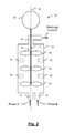
- Fig. 1 shows such a known device 1 in a schematic view, as for example. From EP 1 606 044 B1 is known.
- Two flowable phases A, B are fed to a mixing vessel 4 via two supply lines 2, 3.
- This mixing vessel also has a discharge line 5, which serves to discharge the mixture mixed from these phases.
- the supply lines 2, 3 are arranged at the lower end of the mixing vessel 4, while the discharge line 5 is provided at the upper end of the mixing vessel 4.
- the mixing vessel is cylindrical.
- the supply and discharge lines are provided perpendicular to the cylinder axis.
- a driven by a drive motor 6 stirrer 7 is provided in this known device, which sets the phases to be mixed in rotation. Due to the centrifugal forces occurring during such a rotation, the mixture is forced outwards and the air in the vessel is pressed inwards. At high stirrer speeds, accelerations of more than 1000 m / s 2 can occur. As a result, the material to be mixed, as shown by the line 8, distributed paraboloid. In these cases, the mixture, at least during a starting process, offset with air in the supply line 5 out. This is disadvantageous, since thus air is included in the further production process.
- the mixing vessel 4 is conventionally flooded before switching on the stirrer 7 with one of the phases.
- this leads to increased losses of raw materials during the starting process.
- the invention is therefore based on the problem to improve the production of mixtures of two flowable phases.
- the invention solves this problem by means of a device according to claim 1 and a method according to claim 15.
- an apparatus for the continuous production of a mixture of at least two flowable phases, in particular for the preparation of emulsions or dispersions, with a mixing vessel closed on all sides, rotationally symmetrical about its longitudinal axis or rotationally symmetrical mixing vessel, at least two supply lines leading to the mixing vessel for introducing a flowable one Phase, at least one leading out of the mixing vessel discharge line for discharging a mixture mixed from these phases and a rotatable agitator for stirring the phases whose axis of rotation lies in the longitudinal axis of the mixing vessel, wherein the discharge line is arranged in the region of a first passage of the longitudinal axis through the mixing vessel ,
- a method for continuously producing a mixture of at least two flowable phases, in particular for producing emulsions or dispersions is provided, in which at least two streams of these phases are fed separately to a mixing vessel in which they are stirred by means of a rotating stirrer, the method being carried out in a device according to the invention.
- the discharge line of the mixed product mixed in the mixing vessel is arranged in the center of an end face of the mixing vessel, namely in the region of a passage, ie intersection, of the longitudinal axis of the mixing vessel through the mixing vessel. Due to this central arrangement of the discharge line, only air is initially discharged from the mixing vessel even during a paraboloidal distribution of the mixed material in the mixing vessel during the starting process. Only when the air is substantially completely removed from the mixing vessel, the mixture is discharged from the mixing vessel without disturbing air.
- Another advantage of this design is that the pressure in the mix in the region of the wall of the mixing vessel due to the centrifugal forces is higher than at the discharge line for the mixture. In the area of the wall, however, the highest shear rates occur. Due to the high pressure occurring in the wall in this construction, the risk of cavitation is reduced. In the area of the discharge line, the pressure is lower, so that in principle there would be a greater risk of cavitation. However, only very little or no shear gradient is present in the region of the discharge line, so that the risk of cavitation in the region of the discharge line is low anyway.
- Another advantage is that already during the startup process, the resulting mixture does not have to be removed as scrap, but can be used as a product. This is possible because the mixing vessel can be filled with a rotating stirrer. This results in an already properly mixed mixture without air bubbles, which is discharged via the discharge line. Overall, the risk of air accumulation in the mixing chamber is significantly reduced according to the invention. Air is preferably discharged first. The mixing process is thus easier to approach. Premature discharge of mixed liquids at a time when there is still air in the mixing vessel is avoided.
- At least one or all supply lines are arranged in the region of a second passage of the longitudinal axis through the mixing vessel. This means that the supply lines also take place in a central end region of the mixing vessel.
- the discharge line and at least one or all supply lines can emerge from the mixing vessel either in parallel or at an angle.
- the further course of the lines can then also parallel or inclined at an angle or only parallel and then tilted at an angle or vice versa. Due to the central arrangement of the supply lines and the discharge line, the arrangement of the supply and discharge lines is subject to little restrictions, so that the respective arrangement can fulfill other requirements.
- the mixing vessel is formed like a cylinder.
- the feed and discharge lines are then located on opposite base surfaces of the cylinder.
- the mixing vessel is tapered conically to the discharge line. That the cross-section of the mixing vessel decreases in the direction of the discharge line.
- Such a construction is advantageous because due to the larger radii in the region of the supply line a higher rotational speed of the mixed material and thus a more intensive mixing effect is achieved.
- the phases to be mixed are first mixed very intensively.
- the corresponding volumes are guided in the direction of the discharge line, where the peripheral speeds, in particular in the region of the conversion of the mixing vessel are lower.
- the risk of an excess of the mixture in particular due to the increasing viscosity with increasing processing time, reduced. Overall, this results in an improved quality of the mixture to be produced.
- blades of the stirrer are adapted to the conicity of the mixing vessel, ie the vane radii decrease according to the taper to the discharge line.
- a drive motor of the stirrer is arranged in the region of the supply lines.
- the shaft of the stirrer passes through the supply line.
- flow breakers are provided in the mixing chamber.
- Such flow breakers can be arranged, for example, on the wall of the mixing vessel.
- the mixing vessel can be arranged standing or lying. In a vertical arrangement, the longitudinal axis of the mixing vessel is vertically aligned.
- the supply lines are arranged at a lower portion and the discharge lines at an upper portion of the mixing vessel. The product flow thus takes place from bottom to top, so that air bubbles can preferably escape upwards and can be removed via the discharge line.
- the longitudinal axis is arranged horizontally. This allows installation of the mixing vessel even in places with a small height. Due to the inventive arrangement of the discharge line and possibly the supply lines in a central region of the mixing vessel, the orientation of the mixing vessel is less crucial. This opens up further degrees of freedom in the design of the entire mixing device.
- Fig. 1 has already been discussed in the introduction to explain the state of the art.
- the basic concept namely the mixture of several phases in a continuous process, also applies to the present invention, so that in the above explanations to Fig. 1 Also with regard to the invention reference is made.
- Fig. 2 shows a corresponding apparatus 10 for the continuous production of a mixture of a plurality of flowable phases.
- two phases A and B are fed via separate supply lines 11, 12 to a mixing vessel 13.
- This mixing vessel has a cylindrical configuration in the illustrated embodiment.
- the supply lines 11, 12 are provided on the cylinder bottom and indeed in a central region of the cylinder bottom.
- the mixing vessel 13 has a discharge line 14.
- This discharge line is again in a central region of the front side. This middle region is determined by the passage of the cylinder longitudinal axis 15 through the mixing vessel 13 or through the end faces of the cylinder.
- the supply lines 11, 12 and the discharge line 14 enter the mixing vessel 13 parallel to the longitudinal axis 15. Of the further course of the supply and discharge lines depends on the other local conditions.
- a stirrer 16 which has a stirrer shaft 17 with stirrer blades 18 attached to this stirrer shaft 17.
- stirrer shaft 17 with stirrer blades 18 attached to this stirrer shaft 17.
- wings 18 are provided at preferably uniform intervals.
- the wings 18 are each arranged in pairs or in a group with more than two wings 18 on the shaft 17.
- flow breakers 19 are arranged on the wall of the mixing vessel 13.
- these are simple, arranged on the wall of the mixing vessel 13 strip-like or otherwise formed elements which reduce the rotational speed of the mixed material in the respective region of the flow breaker 19.
- the stirrer shaft 17, which also serves as a drive shaft for the vanes 18, is led out of the mixing vessel 13 through the discharge line 14.
- this shaft 14 is led out through one of the supply lines 11, 12.
- the agitator shaft 17 is connected to a drive motor 20 which causes the stirrer 16, in particular the stirrer blades 18, to rotate.
- the axis 15 is arranged horizontally or obliquely inclined.
- FIG. 3 shows a further embodiment of a device 10 'according to the invention.
- supply lines 21, 22 are arranged on a now conical mixing vessel 23.
- this conical mixing vessel 23 has two opposite end faces.
- the supply lines 21, 22 take place via a first end face, while a discharge line 24 is arranged opposite a second end face located on this first end side.
- the conicity of the mixing vessel 23 is selected such that the diameter of the mixing vessel and thus its cross-section from the region of the supply lines 21, 22 to the region of the discharge line 24 is smaller.
- stirrer 25 has, corresponding to Fig. 2 , several groups of Reckerhoffln 26, which are arranged on a common agitator shaft 27.
- the radii of the stirrer blades 26 are adapted to the respective cross section of the mixing vessel, that is, chosen slightly smaller than the corresponding radii of the mixing vessel 23 at these locations.
- baffles 28 are arranged to reduce the rotational speed of the material to be mixed at least locally.
- the agitator shaft 27 is in turn connected to a drive motor 29, which sets this shaft and thus the wings 26 in rotation.
- the drive motor 29 is arranged on the side of the supply lines.
- the agitator shaft 27 penetrates one of the two supply lines 21.
- the drive motor 29 may also be arranged on the opposite side of the mixing vessel 23. In this alternative arrangement, the agitator shaft 27 penetrates the discharge line 24.
- a longitudinal axis 30 of the mixing vessel can be arranged either vertically or horizontally or obliquely inclined.
- the discharge pipe 24 is disposed at an upper portion of the mixing vessel 23, while the supply pipes 21, 22 are provided at a lower portion.
- the mixing vessels are rotationally symmetrical.
- the mixing vessels can also be rotationally symmetrical about a longitudinal axis, for example, by the flow breakers being integrated directly into the respective wall of the mixing vessel.
- the invention allows due to the removal of the mixed product in the central region of one of the end sides of the mixing vessel, an improvement in the mixing properties of a mixing device and an increase in efficiency of the starting process.
- no comming arises during the starting process due to a flooding of the mixing vessel with only one phase or two not properly mixed phases.
- the invention prevents premature discharge of liquid when there is still air in the mixing vessel. Thanks to the centrifugal forces acting on the rotating material to be mixed, lower density material is conveyed to the longitudinal axis of the mixing vessel, while higher density material moves towards the wall of the mixing vessel.
- air or gas collects in a central region of the mixing vessel and is discharged due to the central arrangement of the discharge line first. As soon as the mixture reaches the area of the discharge line during a start-up process, substantially all of the air previously contained in the mixing vessel is already discharged. There is thus no or only a very small amount of mixed substance.
- Such mixing vessels are particularly suitable for processes in the production of emulsions and dispersions, in which different phases are mixed together.
- the invention provides significant advantages in moderate or low viscosity phases.
Abstract
Description
Die Erfindung betrifft eine Vorrichtung und ein Verfahren zur kontinuierlichen Herstellung einer Mischung aus wenigstens zwei fließfähigen Phasen, insbesondere zur Herstellung von Emulsionen oder Dispersionen. Eine solche Vorrichtung weist ein allseitig geschlossenes, um seine Längsachse rotationssymmetrisches oder drehsymmetrisches Mischgefäß auf. Sie umfasst ferner wenigstens zwei in das Mischgefäß führende Zufuhrleitungen zum Eintrag jeweils einer fließfähigen Phase sowie wenigstens eine aus dem Mischgefäß führenden Austragsleitung zum Austragen einer aus diesen Phasen gemischten Mischung. Ferner weist eine solche Vorrichtung einen rotierbaren Rührer zum Rühren der Phasen auf, dessen Rotationsachse in der Längsachse des Mischgefäßes liegt.The invention relates to an apparatus and a method for the continuous production of a mixture of at least two flowable phases, in particular for the preparation of emulsions or dispersions. Such a device has a closed on all sides, about its longitudinal axis rotationally symmetric or rotationally symmetrical mixing vessel. It also comprises at least two supply lines leading into the mixing vessel for introducing a respective flowable phase and at least one discharge line leading from the mixing vessel for discharging a mixture mixed from these phases. Furthermore, such a device has a rotatable stirrer for stirring the phases whose axis of rotation lies in the longitudinal axis of the mixing vessel.
Über zwei Zufuhrleitungen 2, 3 werden zwei fließfähige Phasen A, B einem Mischgefäß 4 zugeführt. Dieses Mischgefäß weist ferner eine Austragsleitung 5 auf, die dem Austrag der aus diesen Phasen gemischten Mischung dient.Two flowable phases A, B are fed to a
Die Zufuhrleitungen 2, 3 sind am unteren Ende des Mischgefäßes 4 angeordnet, während die Austragsleitung 5 am oberen Ende des Mischgefäßes 4 vorgesehen ist.The
Das Mischgefäß ist zylinderförmig ausgebildet. Die Zufuhr- und Austragsleitungen sind senkrecht zur Zylinderachse vorgesehen.The mixing vessel is cylindrical. The supply and discharge lines are provided perpendicular to the cylinder axis.
Ferner ist bei dieser bekannten Vorrichtung ein von einem Antriebsmotor 6 angetriebener Rührer 7 vorgesehen, der die zu mischenden Phasen in Rotation versetzt. Durch die bei einer derartigen Rotation auftretenden Zentrifugalkräfte wird das Mischgut nach außen und die sich in dem Gefäß befindende Luft nach innen gedrückt. Bei hohen Rührerdrehzahlen können dabei Beschleunigungen von über 1000 m/s2 auftreten. Dies führt dazu, dass sich das zu mischende Gut, wie mit der Linie 8 dargestellt, parabolidartig verteilt. In diesen Fällen wird die Mischung, zumindest während eines Anfahrvorganges, mit Luft versetzt in die Zufuhrleitung 5 geführt. Dies ist nachteilig, da somit Luft im weiteren Produktionsvorgang enthalten ist.Furthermore, a driven by a
Zur Verhinderung dieses Problems wird herkömmlicherweise das Mischgefäß 4 vor dem Einschalten des Rührers 7 mit einer der Phasen geflutet. Dies führt jedoch zu erhöhten Verlusten von Rohstoffen während des Anfahrvorganges.To prevent this problem, the
Ferner kann während des Mischbetriebs durch Ausgasungen der regelmäßig gasgesättigten Phasen aufgrund der niedrigeren Gaslöslichkeit bei höheren Temperaturen und aufgrund des verminderten Druckes dennoch eine Gasblase in dem Mischgefäß entstehen. Unter Umständen kommt es auch zur Bildung einer Dampfblase. Durch derartige Gas- oder Dampfblasen wird jedoch die Mischwirkung deutlich verschlechtert.Furthermore, due to the lower gas solubility at elevated temperatures and due to the reduced pressure, a gas bubble in the mixing vessel can still arise during the mixing operation through outgassing of the regularly gas-saturated phases. Under certain circumstances, it also leads to the formation of a vapor bubble. By such gas or vapor bubbles, however, the mixing effect is significantly deteriorated.
Ferner nimmt aufgrund der Zentrifugalkräfte der Druck in dem zu mischenden Gut von der Längsachse des Mischgefäßes 4 zur Wandung des Mischgefäßes 4 hin zu. Die über die Zufuhrleitungen 2, 3 zugeführten Phasen müssen dann gegen diesen erhöhten Druck dosiert werden. Dies ist nachteilig, insbesondere, da es auf die exakte Dosierung der zuzuführenden Phasen oftmals genau ankommt.Furthermore, due to the centrifugal forces, the pressure in the material to be mixed increases from the longitudinal axis of the
Der Erfindung liegt daher das Problem zugrunde, die Herstellung von Mischungen aus zwei fließfähigen Phasen zu verbessern.The invention is therefore based on the problem to improve the production of mixtures of two flowable phases.
Die Erfindung löst dieses Problem mittels einer Vorrichtung nach Anspruch 1 sowie einem Verfahren nach Anspruch 15.The invention solves this problem by means of a device according to
Erfindungsgemäß ist demnach eine Vorrichtung zur kontinuierlichen Herstellung einer Mischung aus wenigstens zwei fließfähigen Phasen, insbesondere zur Herstellung von Emulsionen oder Dispersionen vorgesehen, mit einem allseitig geschlossenen, um seine Längsachse rotationssymmetrischen oder drehsymmetrischen Mischgefäß, wenigstens zwei in das Mischgefäß führenden Zufuhrleitungen zum Eintrag jeweils einer fließfähigen Phase, wenigstens einer aus dem Mischgefäß führenden Austragsleitung zum Austragen einer aus diesen Phasen gemischten Mischung und einem rotierbaren Rührer zum Rühren der Phasen, dessen Rotationsachse in der Längsachse des Mischgefäßes liegt, wobei die Austragsleitung im Bereich eines ersten Durchtritts der Längsachse durch das Mischgefäß angeordnet ist.According to the invention, therefore, an apparatus is provided for the continuous production of a mixture of at least two flowable phases, in particular for the preparation of emulsions or dispersions, with a mixing vessel closed on all sides, rotationally symmetrical about its longitudinal axis or rotationally symmetrical mixing vessel, at least two supply lines leading to the mixing vessel for introducing a flowable one Phase, at least one leading out of the mixing vessel discharge line for discharging a mixture mixed from these phases and a rotatable agitator for stirring the phases whose axis of rotation lies in the longitudinal axis of the mixing vessel, wherein the discharge line is arranged in the region of a first passage of the longitudinal axis through the mixing vessel ,
Erfindungsgemäß ist ferner ein Verfahren zum kontinuierlichen Herstellen einer Mischung aus wenigstens zwei fließfähigen Phasen, insbesondere zum Herstellen von Emulsionen oder Dispersionen, vorgesehen, bei dem wenigstens zwei Ströme dieser Phasen getrennt kontinuierlich einem Mischgefäß zugeführt werden, in dem sie mittels eines rotierenden Rührers gerührt werden, wobei das Verfahren in einer erfindungsgemäßen Vorrichtung durchgeführt wird.According to the invention, a method for continuously producing a mixture of at least two flowable phases, in particular for producing emulsions or dispersions, is provided, in which at least two streams of these phases are fed separately to a mixing vessel in which they are stirred by means of a rotating stirrer, the method being carried out in a device according to the invention.
Erfindungsgemäß ist die Austragsleitung des im Mischgefäß gemischten Mischproduktes in der Mitte einer Stirnseite des Mischgefäßes, nämlich im Bereich eines Durchtritts, d.h. Schnittpunktes, der Längsachse des Mischgefäßes durch das Mischgefäß angeordnet. Durch diese mittige Anordnung der Austragsleitung wird auch bei einer parabolidartigen Verteilung des Mischgutes im Mischgefäß während des Anfahrvorganges zunächst ausschließlich Luft aus dem Mischgefäß ausgetragen. Erst wenn die Luft im Wesentlichen vollständig aus dem Mischgefäß entfernt ist, wird die Mischung aus dem Mischgefäß ohne störende Luft ausgetragen.According to the invention, the discharge line of the mixed product mixed in the mixing vessel is arranged in the center of an end face of the mixing vessel, namely in the region of a passage, ie intersection, of the longitudinal axis of the mixing vessel through the mixing vessel. Due to this central arrangement of the discharge line, only air is initially discharged from the mixing vessel even during a paraboloidal distribution of the mixed material in the mixing vessel during the starting process. Only when the air is substantially completely removed from the mixing vessel, the mixture is discharged from the mixing vessel without disturbing air.
Ein weiterer Vorteil dieser Konstruktion besteht darin, dass der Druck im Mischgut im Bereich der Wandung des Mischgefäßes aufgrund der Zentrifugalkräfte höher ist als an der Austragsleitung für die Mischung. Im Bereich der Wandung treten jedoch die höchsten Schergefälle auf. Aufgrund des bei dieser Konstruktion im Bereich der Wandung auftretenden hohen Druckes wird die Gefahr von Kavitation verringert. Im Bereich der Austragsleitung ist zwar der Druck geringer, so dass dort grundsätzlich die Gefahr von Kavitation größer wäre. Jedoch sind im Bereich der Austragsleitung nur noch sehr geringe oder keine Schergefälle vorhanden, so dass dadurch die Gefahr von Kavitation im Bereich der Austragsleitung ohnehin gering sind.Another advantage of this design is that the pressure in the mix in the region of the wall of the mixing vessel due to the centrifugal forces is higher than at the discharge line for the mixture. In the area of the wall, however, the highest shear rates occur. Due to the high pressure occurring in the wall in this construction, the risk of cavitation is reduced. In the area of the discharge line, the pressure is lower, so that in principle there would be a greater risk of cavitation. However, only very little or no shear gradient is present in the region of the discharge line, so that the risk of cavitation in the region of the discharge line is low anyway.
Ein weiterer Vorteil liegt darin, dass bereits während des Anfahrvorganges die entstehende Mischung nicht als Ausschuss entfernt werden muss, sondern als Produkt verwendet werden kann. Dies ist deshalb möglich, weil das Mischgefäß bei rotierendem Rührer gefüllt werden kann. Somit entsteht eine bereits ordnungsgemäß durchmischte Mischung ohne Luftblasen, welche über die Austragsleitung ausgetragen wird. Insgesamt ist erfindungsgemäß die Gefahr von Luftansammlungen in der Mischkammer deutlich reduziert. Luft wird bevorzugt zunächst ausgetragen. Der Mischprozess ist dadurch insgesamt einfacher anzufahren. Ein vorzeitiger Austrag von gemischten Flüssigkeiten zu einem Zeitpunkt, in dem im Mischgefäß noch Luft vorhanden ist, wird vermieden.Another advantage is that already during the startup process, the resulting mixture does not have to be removed as scrap, but can be used as a product. This is possible because the mixing vessel can be filled with a rotating stirrer. This results in an already properly mixed mixture without air bubbles, which is discharged via the discharge line. Overall, the risk of air accumulation in the mixing chamber is significantly reduced according to the invention. Air is preferably discharged first. The mixing process is thus easier to approach. Premature discharge of mixed liquids at a time when there is still air in the mixing vessel is avoided.
Bei einer bevorzugten Ausführungsform sind wenigstens eine oder alle Zufuhrleitungen im Bereich eines zweiten Durchtritts der Längsachse durch das Mischgefäß angeordnet. D.h. auch die Zufuhrleitungen erfolgen in einem mittigen stirnseitigen Bereich des Mischgefäßes. Durch diese Anordnung der Zufuhrleitungen erreicht man vorteilhafterweise, dass die zugeführten Phasen nicht gegen den aufgrund der Zentrifugalkräfte im Mischgefäß entstehenden erhöhten Druck im Bereich der Wandung des Mischgefäßes angepumpt werden müssen. Dies erleichtert das dosierte Zuführen der Phasen. Hierdurch wird auch die Auswahl der erforderlichen Dosierpumpen zum Zuführen der zu mischenden Phasen erleichtert. Insbesondere können die Dosierpumpen einfacher hergestellt werden.In a preferred embodiment, at least one or all supply lines are arranged in the region of a second passage of the longitudinal axis through the mixing vessel. This means that the supply lines also take place in a central end region of the mixing vessel. By means of this arrangement of the supply lines, it is advantageously achieved that the supplied phases do not have to be pumped against the increased pressure in the area of the wall of the mixing vessel due to the centrifugal forces in the mixing vessel. This facilitates the metered feeding of the phases. This also facilitates the selection of the required metering pumps for feeding the phases to be mixed. In particular, the metering pumps can be made easier.
Vorteilhafterweise können die Austragsleitung sowie wenigstens eine oder alle Zufuhrleitungen entweder parallel oder winklig geneigt aus dem Mischgefäß austreten. Der weitere Verlauf der Leitungen kann dann ebenfalls parallel oder winklig geneigt oder erst parallel und dann winklig geneigt oder umgekehrt erfolgen. Aufgrund der mittigen Anordnung der Zufuhrleitungen und der Austragsleitung ist die Anordnung der Zufuhr- und Austragsleitungen geringen Beschränkungen unterworfen, so dass die jeweilige Anordnung andere Anforderungen erfüllen kann.Advantageously, the discharge line and at least one or all supply lines can emerge from the mixing vessel either in parallel or at an angle. The further course of the lines can then also parallel or inclined at an angle or only parallel and then tilted at an angle or vice versa. Due to the central arrangement of the supply lines and the discharge line, the arrangement of the supply and discharge lines is subject to little restrictions, so that the respective arrangement can fulfill other requirements.
Bei einer weiteren vorteilhaften Ausführungsform ist das Mischgefäß zylinderartig ausgebildet. Die Zufuhr- und Austragsleitungen befinden sich dann an gegenüberliegenden Grundflächen des Zylinders. Eine derartige Ausbildung des Mischgefäßes ist vorteilhaft, da sie einfach und somit kostengünstig herzustellen ist.In a further advantageous embodiment, the mixing vessel is formed like a cylinder. The feed and discharge lines are then located on opposite base surfaces of the cylinder. Such a design of the mixing vessel is advantageous because it is simple and therefore inexpensive to manufacture.
Bei einer weiteren bevorzugten Ausführungsform ist das Mischgefäß sich konisch zur Austragsleitung verjüngend ausgebildet. D.h. der Querschnitt des Mischgefäßes verringert sich in Richtung der Austragsleitung. Eine derartige Konstruktion ist vorteilhaft, da aufgrund der größeren Radien im Bereich der Zufuhrleitung eine höhere Rotationsgeschwindigkeit des Mischgutes und somit eine intensivere Mischwirkung erzielt wird. Dadurch werden die zu mischenden Phasen zunächst besonders intensiv gemischt. Im weiteren Verlauf des Mischprozesses werden die entsprechenden Volumina in Richtung der Austragsleitung geführt, wo die Umfangsgeschwindigkeiten, insbesondere im Bereich der Umwandung des Mischgefäßes niedriger sind. Dadurch wird die Gefahr einer Überscherung der Mischung, insbesondere auch aufgrund der mit zunehmender Bearbeitungszeit zunehmenden Viskosität, verringert. Insgesamt ergibt sich dadurch eine verbesserte Qualität der zu erzeugenden Mischung.In a further preferred embodiment, the mixing vessel is tapered conically to the discharge line. That the cross-section of the mixing vessel decreases in the direction of the discharge line. Such a construction is advantageous because due to the larger radii in the region of the supply line a higher rotational speed of the mixed material and thus a more intensive mixing effect is achieved. As a result, the phases to be mixed are first mixed very intensively. In the further course of the mixing process, the corresponding volumes are guided in the direction of the discharge line, where the peripheral speeds, in particular in the region of the conversion of the mixing vessel are lower. As a result, the risk of an excess of the mixture, in particular due to the increasing viscosity with increasing processing time, reduced. Overall, this results in an improved quality of the mixture to be produced.
Vorteilhafterweise sind Flügel des Rührers an die Konizität des Mischgefäßes angepasst, d.h. die Flügelradien nehmen entsprechend der Konizität zur Austragsleitung hin ab. Durch eine derartige Ausbildung der Flügel des Rührers werden die vorstehend beschriebenen Vorgänge im Hinblick auf die höheren Umfangsgeschwindigkeiten im Bereich der Zufuhrleitung und der niedrigeren Umfangsgeschwindigkeit im Bereich der Austragsleitung weiter verstärkt, so dass hierdurch die Produktqualität weiter verbessert wird.Advantageously, blades of the stirrer are adapted to the conicity of the mixing vessel, ie the vane radii decrease according to the taper to the discharge line. By thus constituting the blades of the agitator, the above-described operations become favorable in view of the higher peripheral speeds in the region of the supply pipe and the lower peripheral speed In the field of discharge management further strengthened, so that thereby the product quality is further improved.
Bei einer weiteren bevorzugten Ausführungsform ist ein Antriebsmotor des Rührers im Bereich der Zufuhrleitungen angeordnet. Die Welle des Rührers geht dabei durch die Zufuhrleitung hindurch. Eine derartige Anordnung ist vorteilhaft, da die entsprechende Wellendichtung somit lediglich von einer zugeführten Phase umspült wird. Die Dichtung muss daher nur an diese Phase angepasst werden. Dies vereinfacht die Auswahl der Dichtung. Ein Austausch der Dichtung wird dabei vereinfacht.In a further preferred embodiment, a drive motor of the stirrer is arranged in the region of the supply lines. The shaft of the stirrer passes through the supply line. Such an arrangement is advantageous because the corresponding shaft seal is thus only washed around by a supplied phase. The seal must therefore be adapted only to this phase. This simplifies the selection of the seal. An exchange of the seal is simplified.
Bei einer weiteren besonderen Ausführungsform sind in der Mischkammer Strömungsbrecher vorgesehen. Derartige Strömungsbrecher können bspw. an der Wandung des Mischgefäßes angeordnet sein. Mittels dieser Strömungsbrecher kann die Rotationsgeschwindigkeit des zu mischenden Gutes zumindest partiell verringert werden. Dies verbessert die Scherwirkung des Rührers.In a further particular embodiment, flow breakers are provided in the mixing chamber. Such flow breakers can be arranged, for example, on the wall of the mixing vessel. By means of these flow breakers, the rotational speed of the material to be mixed can be at least partially reduced. This improves the shearing action of the stirrer.
Das Mischgefäß kann stehend oder liegend angeordnet werden. Bei einer stehenden Anordnung ist die Längsachse des Mischgefäßes vertikal ausgerichtet. Vorteilhafterweise sind dabei die Zufuhrleitungen an einem unteren Abschnitt und die Austragsleitungen an einem oberen Abschnitt des Mischgefäßes angeordnet. Der Produktstrom erfolgt somit von unten nach oben, so dass Luftblasen bevorzugt nach oben austreten und über die Austragsleitung abgeführt werden können.The mixing vessel can be arranged standing or lying. In a vertical arrangement, the longitudinal axis of the mixing vessel is vertically aligned. Advantageously, the supply lines are arranged at a lower portion and the discharge lines at an upper portion of the mixing vessel. The product flow thus takes place from bottom to top, so that air bubbles can preferably escape upwards and can be removed via the discharge line.
Bei einer alternativen Ausführungsform ist die Längsachse horizontal angeordnet. Dies ermöglicht eine Installation des Mischgefäßes auch an Orten mit einer geringen Höhe. Aufgrund der erfindungsgemäßen Anordnung der Austragsleitung und ggf. der Zufuhrleitungen in einem mittigen Bereich des Mischgefäßes ist die Ausrichtung des Mischgefäßes weniger entscheidend. Dies eröffnet weitere Freiheitsgrade bei der Konstruktion der gesamten Mischvorrichtung.In an alternative embodiment, the longitudinal axis is arranged horizontally. This allows installation of the mixing vessel even in places with a small height. Due to the inventive arrangement of the discharge line and possibly the supply lines in a central region of the mixing vessel, the orientation of the mixing vessel is less crucial. This opens up further degrees of freedom in the design of the entire mixing device.
Weitere vorteilhafte Ausführungsformen ergeben sich aus den Unteransprüchen sowie aus den anhand der beigefügten Zeichnung näher erläuterten Ausführungsbeispiele. In der Zeichnung zeigen:
- Fig. 1
- eine Mischvorrichtung gemäß dem Stand der Technik;
- Fig. 2
- ein erstes Ausführungsbeispiel einer erfindungsgemäßen Mischvorrichtung und
- Fig. 3
- ein zweites Ausführungsbeispiel einer erfindungsgemäßen Mischvorrichtung.
- Fig. 1
- a mixing device according to the prior art;
- Fig. 2
- a first embodiment of a mixing device according to the invention and
- Fig. 3
- A second embodiment of a mixing device according to the invention.
An der gegenüberliegenden Stirnseite des Zylinders weist das Mischgefäß 13 eine Austragsleitung 14 auf. Diese Austragsleitung befindet sich wiederum in einem mittleren Bereich der Stirnseite. Dieser mittlere Bereich wird bestimmt durch den Durchtritt der Zylinderlängsachse 15 durch das Mischgefäß 13 bzw. durch die Stirnseiten des Zylinders. Die Zufuhrleitungen 11, 12 sowie die Austragsleitung 14 treten parallel zur Längsachse 15 in das Mischgefäß 13 ein. Der weitere Verlauf der Zufuhr- und Austragsleitungen ist von den weiteren örtlichen Gegebenheiten abhängig.At the opposite end face of the cylinder, the mixing
Innerhalb des Mischgefäßes 13 befindet sich ein Rührer 16, der eine Rührerwelle 17 mit an dieser Rührerwelle 17 befestigten Rührerflügeln 18 aufweist. Entlang der Rührerwelle 17 sind in vorzugsweise gleichmäßigen Abständen derartige Flügel 18 vorgesehen. Die Flügel 18 sind jeweils paarweise oder in einer Gruppe mit mehr als zwei Flügeln 18 an der Welle 17 angeordnet.Within the mixing
Bei einer alternativen Ausführungsform sind zwischen derartigen Gruppen von Rührerflügeln 18 Strömungsbrecher 19 an der Wandung des Mischgefäßes 13 angeordnet. Bspw. handelt es sich hierbei um einfache, an der Wandung des Mischgefäßes 13 angeordnete streifenartige oder auf andere Weise ausgebildete Elemente, welche die Rotationsgeschwindigkeit des Mischgutes in dem jeweiligen Bereich des Strömungsbrechers 19 verringern.In an alternative embodiment, between these groups of
Die Rührerwelle 17, welche zugleich als Antriebswelle für die Flügel 18 dient, wird durch die Austragsleitung 14 aus dem Mischgefäß 13 herausgeführt.The
Bei einer alternativen Ausführungsform wird diese Welle 14 durch eine der Zufuhrleitungen 11, 12 herausgeführt.In an alternative embodiment, this
Die Rührerwelle 17 ist mit einem Antriebsmotor 20 verbunden, welcher den Rührer 16, insbesondere die Rührerflügel 18 in Rotation versetzt.The
In der in
Bei einem alternativen, nicht gezeigten Ausführungsbeispiel ist die Achse 15 jedoch horizontal oder schräg geneigt angeordnet.In an alternative, not shown embodiment, however, the
Die Konizität des Mischgefäßes 23 ist derart gewählt, dass der Durchmesser des Mischgefäßes und damit sein Querschnitt vom Bereich der Zufuhrleitungen 21, 22 zum Bereich der Austragsleitung 24 hin kleiner wird.The conicity of the mixing
Ein innerhalb des Mischgefäßes 23 angeordneter Rührer 25 weist, korrespondierend zu
Die Rührerwelle 27 ist wiederum mit einem Antriebsmotor 29 verbunden, welcher diese Welle und damit die Flügel 26 in Rotation versetzt.The
Im Unterschied zu
Entsprechend den obigen Ausführungen zur Anordnung der Längsachse des Gefäßes gilt auch für das Ausführungsbeispiel gemäß
In den beschriebenen Ausführungsbeispielen sind die Mischgefäße rotationssymmetrisch ausgebildet. Alternativ können die Mischgefäße jedoch auch drehsymmetrisch um eine Längsachse ausgebildet sein, bspw. indem die Strömungsbrecher direkt in die jeweilige Wandung des Mischgefäßes integriert sind.In the described embodiments, the mixing vessels are rotationally symmetrical. Alternatively, however, the mixing vessels can also be rotationally symmetrical about a longitudinal axis, for example, by the flow breakers being integrated directly into the respective wall of the mixing vessel.
Insgesamt ermöglicht die Erfindung aufgrund der Entnahme des gemischten Produktes im mittigen Bereich einer der Stirnseiten des Mischgefäßes eine Verbesserung der Mischeigenschaften einer Mischvorrichtung sowie einer Effizienzsteigerung des Anfahrvorganges. Insbesondere entsteht beim Anfahrvorgang kein Ausschuss aufgrund einer Flutung des Mischgefäßes mit nur einer Phase bzw. zwei nicht ordentlich durchgemischten Phasen. Insbesondere verhindert die Erfindung einen vorzeitigen Austrag von Flüssigkeit, wenn sich im Mischgefäß noch Luft befindet. Dank der wirkenden Zentrifugalkräfte, welche auf das rotierende, zu mischende Gut einwirken, wird Material mit niedrigerer Dichte zur Längsachse des Mischgefäßes hin gefördert, während Material mit einer höheren Dichte sich in Richtung der Wandung des Mischgefäßes bewegt. Durch diesen Effekt sammelt sich Luft bzw. Gas in einem zentralen Bereich des Mischgefäßes und wird aufgrund der zentralen Anordnung der Austragsleitung zuerst ausgetragen. Sobald Mischgut während eines Anfahrvorganges den Bereich der Austragsleitung erreicht, ist im Wesentlichen die gesamte zuvor in dem Mischgefäß enthaltene Luft bereits ausgetragen. Es entsteht somit kein oder nur ein sehr geringer Ausschuss der gemischten Substanz.Overall, the invention allows due to the removal of the mixed product in the central region of one of the end sides of the mixing vessel, an improvement in the mixing properties of a mixing device and an increase in efficiency of the starting process. In particular, no comming arises during the starting process due to a flooding of the mixing vessel with only one phase or two not properly mixed phases. In particular, the invention prevents premature discharge of liquid when there is still air in the mixing vessel. Thanks to the centrifugal forces acting on the rotating material to be mixed, lower density material is conveyed to the longitudinal axis of the mixing vessel, while higher density material moves towards the wall of the mixing vessel. By this effect, air or gas collects in a central region of the mixing vessel and is discharged due to the central arrangement of the discharge line first. As soon as the mixture reaches the area of the discharge line during a start-up process, substantially all of the air previously contained in the mixing vessel is already discharged. There is thus no or only a very small amount of mixed substance.
Derartige Mischgefäße eignen sich insbesondere für Prozesse bei der Herstellung von Emulsionen und Dispersionen, bei denen unterschiedliche Phasen miteinander gemischt werden. Insbesondere erzielt die Erfindung signifikante Vorteile bei Phasen von mäßiger oder niedriger Viskosität.Such mixing vessels are particularly suitable for processes in the production of emulsions and dispersions, in which different phases are mixed together. In particular, the invention provides significant advantages in moderate or low viscosity phases.
Claims (15)
dadurch gekennzeichnet, dass
wenigstens eine oder alle Zufuhrleitungen (11, 12; 21, 22) im Bereich eines zweiten Durchtritts der Längsachse (15; 30) durch das Mischgefäß (13; 23) angeordnet sind.Device according to claim 1,
characterized in that
at least one or all supply lines (11, 12, 21, 22) are arranged in the region of a second passage of the longitudinal axis (15, 30) through the mixing vessel (13, 23).
dadurch gekennzeichnet, dass
die Austragsleitung (14; 24) parallel oder winklig geneigt aus dem Mischgefäß (13; 23) austritt.Apparatus according to claim 1 or 2,
characterized in that
the discharge line (14; 24) emerges from the mixing vessel (13; 23) in parallel or at an angle.
dadurch gekennzeichnet, dass
wenigstens eine oder alle Zufuhrleitungen (11, 12; 21, 22) parallel oder winklig geneigt aus dem Mischgefäß (13; 23) austreten.Device according to one of the preceding claims,
characterized in that
at least one or all supply lines (11, 12, 21, 22) emerge from the mixing vessel (13, 23) in parallel or at an angle.
dadurch gekennzeichnet, dass
das Mischgefäß (13) zylinderartig ausgebildet ist.Device according to one of the preceding claims,
characterized in that
the mixing vessel (13) is cylindrical.
dadurch gekennzeichnet, dass das Mischgefäß (23) konisch ausgebildet ist.Device according to one of claims 1 to 4,
characterized in that the mixing vessel (23) is conical.
dadurch gekennzeichnet, dass
das Mischgefäß (23) sich konisch zur Austragsleitung (24) verjüngend ausgebildet ist.Device according to claim 6,
characterized in that
the mixing vessel (23) is tapered conically to the discharge line (24).
dadurch gekennzeichnet, dass
die Flügel (26) des Rührers (25) an die Konizität des Mischgefäßes (23) angepasst ausgebildet sind, insbesondere die Flügel (26) zur Austragsleitung (24) hin kleiner werdend ausgebildet sind.Apparatus according to claim 6 or 7,
characterized in that
the wings (26) of the stirrer (25) are formed adapted to the conicity of the mixing vessel (23), in particular the wings (26) to the discharge line (24) are formed towards becoming smaller.
dadurch gekennzeichnet, dass
ein Antriebsmotor (15; 29) des Rührers (16; 25) im Bereich der Zufuhrleitungen (11, 12; 21, 22) angeordnet ist.Device according to one of the preceding claims,
characterized in that
a drive motor (15; 29) of the stirrer (16; 25) is arranged in the region of the supply lines (11,12; 21,22).
dadurch gekennzeichnet, dass
der Rührer (16; 25) eine Antriebswelle (17; 27) aufweist, die durch eine der Zufuhrleitungen (11, 12; 21, 22) oder die Austragsleitung (14; 24) geführt ist.Device according to one of the preceding claims,
characterized in that
the stirrer (16; 25) has a drive shaft (17; 27) which is guided through one of the supply lines (11, 12; 21, 22) or the discharge line (14; 24).
dadurch gekennzeichnet, dass
das Mischgefäß (13; 23) Strömungsbrecher (19; 28) aufweist.Device according to one of the preceding claims,
characterized in that
The mixing vessel (13, 23) has flow breakers (19, 28).
dadurch gekennzeichnet, dass
die Längsachse (15; 30) vertikal angeordnet ist.Device according to one of the preceding claims,
characterized in that
the longitudinal axis (15; 30) is arranged vertically.
dadurch gekennzeichnet, dass die Zufuhrleitungen (11, 12; 21, 22) an einem unteren Abschnitt und die Austragsleitung (14; 24) an einem oberen Abschnitt des Mischgefäßes (13; 23) angeordnet sind.Device according to claim 12,
characterized in that the supply lines (11, 12; 21, 22) are arranged at a lower portion and the discharge line (14; 24) at an upper portion of the mixing vessel (13; 23).
dadurch gekennzeichnet, dass die Längsachse (15; 30) horizontal angeordnet ist.Device according to one of claims 1 to 11,
characterized in that the longitudinal axis (15; 30) is arranged horizontally.
Applications Claiming Priority (1)
| Application Number | Priority Date | Filing Date | Title |
|---|---|---|---|
| DE102007005622A DE102007005622A1 (en) | 2007-01-31 | 2007-01-31 | Liquid phases e.g. emulsions, mixture producing device, has discharge pipe arranged within region of passage of longitudinal axis through mixing vessel that is symmetrically rotated around its longitudinal axis |
Publications (2)
| Publication Number | Publication Date |
|---|---|
| EP1964604A2 true EP1964604A2 (en) | 2008-09-03 |
| EP1964604A3 EP1964604A3 (en) | 2009-03-18 |
Family
ID=39402889
Family Applications (1)
| Application Number | Title | Priority Date | Filing Date |
|---|---|---|---|
| EP08150816A Withdrawn EP1964604A3 (en) | 2007-01-31 | 2008-01-30 | Method and device for continuous production of a mixture composed of at least two different flow-capable phases |
Country Status (2)
| Country | Link |
|---|---|
| EP (1) | EP1964604A3 (en) |
| DE (1) | DE102007005622A1 (en) |
Cited By (3)
| Publication number | Priority date | Publication date | Assignee | Title |
|---|---|---|---|---|
| DE102010028774A1 (en) | 2010-05-07 | 2011-11-10 | Otc Gmbh | Emulsifying device for the continuous production of emulsions and / or dispersions |
| JP2012115808A (en) * | 2010-12-03 | 2012-06-21 | Heungbo Tech Co Ltd | Homogeneously kneading apparatus |
| WO2017046017A1 (en) * | 2015-09-14 | 2017-03-23 | Wacker Chemie Ag | Process for continuous production of stable silicone emulsions |
Families Citing this family (2)
| Publication number | Priority date | Publication date | Assignee | Title |
|---|---|---|---|---|
| DE102009040454A1 (en) * | 2009-08-27 | 2011-03-24 | Otc Verwaltungs Gmbh | Continuous production of pearlescent dispersion made of pearlescer and dispersant, comprises e.g. dosing a flowable stream made by pre-heating two phases of the pearlescent dispersion into mixing vessel |
| US20210346855A1 (en) * | 2018-09-05 | 2021-11-11 | Tanaka Holdings Co., Ltd. | Liquid stirring apparatus |
Citations (1)
| Publication number | Priority date | Publication date | Assignee | Title |
|---|---|---|---|---|
| EP1606044B1 (en) | 2003-03-21 | 2006-09-27 | Kemira Pigments Oy | Device and method for continuously producing emulsions or dispersions |
Family Cites Families (9)
| Publication number | Priority date | Publication date | Assignee | Title |
|---|---|---|---|---|
| US3807703A (en) * | 1972-10-12 | 1974-04-30 | Usm Corp | Mixer-emulsators |
| US4155657A (en) * | 1978-03-10 | 1979-05-22 | Chemed Corporation | Continuous mixer for preparing emulsions |
| SU1368182A1 (en) * | 1985-10-08 | 1988-01-23 | Предприятие П/Я Х-5312 | Mixer |
| CH677116A5 (en) * | 1989-01-25 | 1991-04-15 | Inst Mikrobiologii Imeni A Kir | |
| US4951262A (en) * | 1989-04-18 | 1990-08-21 | Halliburton Company | Agitator and baffles for slurry mixing |
| US5250576A (en) * | 1991-08-12 | 1993-10-05 | The Procter & Gamble Company | Process for preparing emulsions that are polymerizable to absorbent foam materials |
| DE19818738C2 (en) * | 1998-04-27 | 2000-05-25 | Waeschle Gmbh | Method and device for reducing the solids concentration of a dispersion of liquid and solid particles |
| US20030227817A1 (en) * | 2002-04-11 | 2003-12-11 | Mobius Technologies, Inc., A California Corporation | Mixer |
| GB0318449D0 (en) * | 2003-08-06 | 2003-09-10 | Glaxo Group Ltd | Impeller unit |
-
2007
- 2007-01-31 DE DE102007005622A patent/DE102007005622A1/en not_active Ceased
-
2008
- 2008-01-30 EP EP08150816A patent/EP1964604A3/en not_active Withdrawn
Patent Citations (1)
| Publication number | Priority date | Publication date | Assignee | Title |
|---|---|---|---|---|
| EP1606044B1 (en) | 2003-03-21 | 2006-09-27 | Kemira Pigments Oy | Device and method for continuously producing emulsions or dispersions |
Cited By (11)
| Publication number | Priority date | Publication date | Assignee | Title |
|---|---|---|---|---|
| DE102010028774A1 (en) | 2010-05-07 | 2011-11-10 | Otc Gmbh | Emulsifying device for the continuous production of emulsions and / or dispersions |
| WO2011138438A1 (en) | 2010-05-07 | 2011-11-10 | Otc Gmbh | Emulsification device for continuously producing emulsions and/or dispersions |
| CN102946983A (en) * | 2010-05-07 | 2013-02-27 | Otc股份有限公司 | Emulsification device for continuously producing emulsions and/or dispersions |
| JP2013532047A (en) * | 2010-05-07 | 2013-08-15 | オー・ティー・シー ジー・エム・ビー・エイチ | Emulsifying device for continuous production of emulsion and / or dispersion |
| KR20130113935A (en) * | 2010-05-07 | 2013-10-16 | 오티씨 게엠베하 | Emulsification device for continuously producing emulsions and/or dispersions |
| CN102946983B (en) * | 2010-05-07 | 2014-12-17 | Otc股份有限公司 | Emulsification device for continuously producing emulsions and/or dispersions |
| US9555380B2 (en) | 2010-05-07 | 2017-01-31 | Clariant International Ag | Emulsification device for continuously producing emulsions and/or dispersions |
| US10610835B2 (en) | 2010-05-07 | 2020-04-07 | Clariant International Ag | Emulsification device for continuously producing emulsions and/or dispersions |
| JP2012115808A (en) * | 2010-12-03 | 2012-06-21 | Heungbo Tech Co Ltd | Homogeneously kneading apparatus |
| WO2017046017A1 (en) * | 2015-09-14 | 2017-03-23 | Wacker Chemie Ag | Process for continuous production of stable silicone emulsions |
| US10561995B2 (en) | 2015-09-14 | 2020-02-18 | Wacker Chemie Ag | Process for continuous production of stable silicone emulsions |
Also Published As
| Publication number | Publication date |
|---|---|
| DE102007005622A1 (en) | 2008-08-07 |
| EP1964604A3 (en) | 2009-03-18 |
Similar Documents
| Publication | Publication Date | Title |
|---|---|---|
| EP0516921B1 (en) | Gasing stirrer | |
| EP1771241B1 (en) | Dynamic mixer and its use | |
| EP2262582B1 (en) | Stirred-tank reactor and method for carrying out a polymerisation reaction using said type of stirred-tank reactor | |
| EP2285476B1 (en) | Rotor/stator system and process for producing dispersions | |
| EP1792643B1 (en) | High volume reactor and/or thin film evaporator employing a premixing device | |
| EP2720783B1 (en) | System for dispersing finely dispersed solids into high-viscosity products | |
| DE602005003356T2 (en) | METHOD, DEVICE AND ROTOR FOR HOMOGENIZING A MEDIUM | |
| EP3202489B1 (en) | Device for homogenizing and/or dispersing flowable products | |
| EP2140920B1 (en) | Twisting element, inlet valve, device and method of removing gas from fluids | |
| EP1964604A2 (en) | Method and device for continuous production of a mixture composed of at least two different flow-capable phases | |
| DE102008045820A1 (en) | Transition elements for passing a dispersion in the treatment in a rotor-stator dispersing machine | |
| DE4008943A1 (en) | MIXING DEVICE | |
| DE19537303B4 (en) | Device for homogenizing flowable substances | |
| EP1175255B1 (en) | Method and device for processing a substance or substance mixture which is situated in a container and rotates about the container axis, notably because of a mixing or stirring action | |
| EP0760254B1 (en) | Device for homogenising flowable materials | |
| EP2683487B1 (en) | Stirred ball mill | |
| EP3290094B1 (en) | Device and method for removing gas from a liquid | |
| EP2818234B1 (en) | Device for storing viscous media | |
| DE3919828C2 (en) | Loop reactor | |
| WO2004105924A1 (en) | Device for frothing a sludge | |
| DE2216444A1 (en) | MIXING DEVICE FOR THE PRODUCTION OF A HOMOGENOUS MIXTURE FROM SEVERAL MATERIAL COMPONENTS | |
| DE2727088A1 (en) | GAS-LIQUID CONTACT DEVICE | |
| DE836345C (en) | Device for the continuous mixing of two substances | |
| EP1920822A2 (en) | Device and method for continuous mixing and degassing of solid and/or liquid substances | |
| EP3189887A1 (en) | Cavitation reactor for treating flowable substances |
Legal Events
| Date | Code | Title | Description |
|---|---|---|---|
| PUAI | Public reference made under article 153(3) epc to a published international application that has entered the european phase |
Free format text: ORIGINAL CODE: 0009012 |
|
| AK | Designated contracting states |
Kind code of ref document: A2 Designated state(s): AT BE BG CH CY CZ DE DK EE ES FI FR GB GR HR HU IE IS IT LI LT LU LV MC MT NL NO PL PT RO SE SI SK TR |
|
| AX | Request for extension of the european patent |
Extension state: AL BA MK |
|
| PUAL | Search report despatched |
Free format text: ORIGINAL CODE: 0009013 |
|
| AK | Designated contracting states |
Kind code of ref document: A3 Designated state(s): AT BE BG CH CY CZ DE DK EE ES FI FR GB GR HR HU IE IS IT LI LT LU LV MC MT NL NO PL PT RO SE SI SK TR |
|
| AX | Request for extension of the european patent |
Extension state: AL BA MK |
|
| AKX | Designation fees paid | ||
| STAA | Information on the status of an ep patent application or granted ep patent |
Free format text: STATUS: THE APPLICATION IS DEEMED TO BE WITHDRAWN |
|
| 18D | Application deemed to be withdrawn |
Effective date: 20090919 |
|
| REG | Reference to a national code |
Ref country code: DE Ref legal event code: 8566 |