EP1972896A2 - Human-machine interface for supporting a pilot when taking off and landing an aircraft in low visibility - Google Patents
Human-machine interface for supporting a pilot when taking off and landing an aircraft in low visibility Download PDFInfo
- Publication number
- EP1972896A2 EP1972896A2 EP08004318A EP08004318A EP1972896A2 EP 1972896 A2 EP1972896 A2 EP 1972896A2 EP 08004318 A EP08004318 A EP 08004318A EP 08004318 A EP08004318 A EP 08004318A EP 1972896 A2 EP1972896 A2 EP 1972896A2
- Authority
- EP
- European Patent Office
- Prior art keywords
- machine interface
- layer
- man
- interface according
- ground
- Prior art date
- Legal status (The legal status is an assumption and is not a legal conclusion. Google has not performed a legal analysis and makes no representation as to the accuracy of the status listed.)
- Granted
Links
Images


Classifications
-
- G—PHYSICS
- G01—MEASURING; TESTING
- G01C—MEASURING DISTANCES, LEVELS OR BEARINGS; SURVEYING; NAVIGATION; GYROSCOPIC INSTRUMENTS; PHOTOGRAMMETRY OR VIDEOGRAMMETRY
- G01C23/00—Combined instruments indicating more than one navigational value, e.g. for aircraft; Combined measuring devices for measuring two or more variables of movement, e.g. distance, speed or acceleration
Definitions
- the invention relates to a human-machine interface (MMI) for pilot support during take-off and landing of an aircraft, in particular a helicopter in a reduced external view or in restricted visibility conditions.
- MMI human-machine interface
- helicopter landing In arid, desert-like areas (such as Afghanistan), almost every helicopter landing is a major source of sand and dust. This is caused by the so-called down-wash of the main rotor.
- the sand or Staubaufwirbelung often causes the pilot loses the cockpit outside view in whole or in part - the so-called brown-out. Due to the loss of the external view, the pilot is at risk of losing the spatial orientation and this in particular with regard to pitch and / or roll angle as well as unwanted lateral drift of the aircraft.
- a helicopter landing aid for brown-out conditions which combines environment information and flight condition data generated for pilot support by means of different sensors and continuously updated by means of a helicopter data bus.
- the environment information on the one hand and flight condition data such as speed, movement and drift direction and altitude over ground on the other hand are displayed in a common display.
- the pilot is visually displayed all the information necessary for a brown-out landing on a single display device, so that it is possible to land the helicopter in an intuitive manner based solely on the Brown-Out MMI invention.
- the brown-out MMI consists of a plurality of graphics layers, shown one above the other, in order to suit the criteria for position and movement control in a suitable manner.
- Each of these layers contains certain graphic primitives and symbols, which in total define the complete Brown-Out MMI.
- graphic or alphanumeric characters which characterize the presence of a brown-out state can be displayed in the MMI according to the invention.
- the totality of such characters is referred to below as a BOUT layer.
- this layer informs the pilot of the functionality of the MMI superior Brown Out Recovery System in the event of a partial or complete loss of the cockpit external view.
- the cockpit exterior view is partially or completely obscured by swirling sand and dust.
- How a Brown-Out Recovery System superordinate to the Brown-Out MMI recognizes such a condition (manually by a pilot action or automatically) and how the 3D scene data is managed during the Brown-Out (representation from a previously accumulated history / database, automatic, algorithmic filtering of the dust data or sensor technology "look through" by the cloud) is irrelevant for the MMI according to the invention, ie The Brown-Out MMI works the same way in all these constellations.
- the MMI according to the invention can be used universally under operational conditions. It provides intuitive pilot assistance in spatial orientation during landing, especially under brown-out conditions.
- a single display eg multifunction display MFD, a head-up display HUD, a helmet-mounted display HMD
- the present invention can be found in Any brown-out recovery system based on the principle of visual guidance.
- a further advantage of the present invention is that the MMI according to the invention is also applicable to pilot support under so-called white-out conditions in which a similar critical situation exists as with brown-out due to the swirling up of loose snow and ice crystals.
- Fig. 1 shows a schematic representation of the base layer. It consists of a base area, which has the purpose to illustrate to the pilot in general, ie qualitatively, the flight altitude over ground as well as the momentary attitude.
- the base area represents an idealized floor area, calculated only on the basis of the instantaneous value of the altitude over ground and the current flight condition data, ie without taking into account the real topography of the ground.
- the base area is limited in the direction away from the pilot by the artificial horizon, which basically has the same functionality as an attitude indicator in the cockpit. Due to the artificial horizon of the Brown-Out MMI, the pilot can change attitude changes. Read off pitch and / or roll angle easily. In order to improve the spatial impression, the better estimate of the current attitude and the altitude over ground, additional escape and distance lines are drawn on the base surface of the base layer.
- All graphical elements of the base layer are updated using the current flight state data (attitude) and the current altitude above ground (AGL). This ensures that any changes in attitude and altitude over ground will immediately cause a corresponding change in the graphics display of the base layer.
- the spatial impression - in particular with regard to the estimation of the altitude above ground - can be further increased if the base area is entirely or partially occupied by a checkerboard pattern or a graphic ground texture or both.
- An example of a concrete realization of such a base layer is in Fig. 2 shown.
- the associated flight attitude is also symbolized on the lower right in the separate illustration.
- the 3D scene layer is above the base layer. It represents a positionally accurate image of the real 3-dimensional world in the direction of the flight path of the helicopter. Positional means that the relative location differences shown between the flying object and the objects of the environment correspond to reality.
- escape and distance lines may be present as in Fig. 3 located. Also, the approximated 3D floor surface may be fully or partially occupied with a checkerboard or floor texture.
- the non-ground objects can be numerically analyzed to graphically highlight all or only certain types of these non-ground objects (e.g., lines, guy wires and masts) in the 3D scene layer.
- the numerical analysis is done by segmentation, i. the objects as such are separated from the ground, and / or classification according to predetermined object or obstacle types.
- Such an extension of the Brown-Out MMI further improves the spatial orientation and warns the pilot of dangerous obstacles in the flight path.
- all or some of the segmented or classified non-ground objects are completely or partially occupied with a graphic pattern or an object texture.
- the approximated 3D bottom surface and / or the segmented or classified non-ground objects may be fully or partially highlighted by graphical image enhancement in the form of artificial shadowing or self-illumination.
- Fig. 5 shows a concrete execution of the 3D scene layer with underlying base layer. In the middle of the picture you can see a high voltage line as well as trees / bushes at the edge of the field left and above. The associated attitude is shown in the separate picture at the bottom right.
- All graphical elements of the 3D scene layer are updated using the current flight state data (attitude and velocity) and the current altitude above ground (AGL). This ensures that any changes in attitude, airspeed, and elevation above ground will immediately cause a corresponding change in the graphics display of the 3D scene layer without noticeable time delay. It creates a kind of "virtual reality" impression.
- the ground and non-ground 3D information can be from either a RADAR, an ultrasound system, a laser-based LADAR, or other suitable active measuring system, or can be calculated by stereoscopy (numerical depth calculation from two or more images).
- a 3D sensor is preferably a distance imaging sensor, in particular an imaging laser radar used, as for example in the DE 39 42 770 C2 or DE 43 20 485 A1 is described. Particularly suitable is, for example, the helicopter laser radar HELLAS ® from EADS Germany GmbH, Ottobrunn, which provides 40,000 pixels / s with a range of up to 1.2 km.
- the concrete graphical implementation examples for the Brown-Out MMI shown in the figures are based on the 3D data of this sensor.
- attitude reference and navigation equipment e.g., Aerodata Flugmesstechnik GmbH or Honeywell International Inc.
- the altitude over ground can either be calculated numerically from the measured velocity vector components or the AGL altitude is also measured via RADAR, LADAR, ultrasound, etc.
- suitable methods from digital image processing with the aid of which the position and movement of the helicopter is calculated on the basis of a so-called optical flow based on an image sequence analysis.
- the 3D information of the 3D scene layer for the ground surface and for the non-ground objects can be accumulated (a) until just prior to the brown-out state and cached in a parent Brown-Out Recovery System before being used in 3D scenes -Layers during the Brown-Out to the ad or (b) be detected by a sensor system which penetrates completely or partially through the so-called brown-out roll of sand or dust.
- the 3D information about the non-ground objects is primarily used for spatial orientation and for estimating the attitude and altitude above ground, it is not mandatory that the non-visible backs of these objects are completely and correctly reconstructed. That is, the backsets allow simplifying assumptions about the actual geometry of these objects. These simplifications on the backs of the objects do not lead to a loss of orientation, since primarily the majesty of the objects above the floor surface, their basic geometric shape and in particular their correct position in relation to the helicopter represent the decisive parameters.
- the geometry of the non-floor objects must be reconstructed on their visible fronts only to a certain degree of detail. It is quite sufficient to consider only the general geometric structure and the most important spatial dimensions of the non-ground objects in the representation in the 3D scene layer. This does not affect the position and orientation of the viewer. However, considering the necessary hardware cost and processing time, the goal should be to fine-tune and accurately reconstruct the geometry of the object when displaying the 3D scene layer to allow the viewer an intuitive yet relatively accurate estimate of attitude and altitude ,
- the base layer and the 3D scene layer allow spatial orientation and control of the attitude as well as estimation of the height above ground in the Brown-Out case.
- the superimposed hover layer uses a special symbol to show the speed over ground and the direction of the current direction of movement or drift in relation to the helicopter's longitudinal axis.
- the hover layer ( Fig. 6 ) consists essentially of two concentric circles and the so-called drift indicator, which is connected to a virtual rubber band with the center of the hover-layer symbolism.
- the same applies to the outer concentric circle of the hover layer with the difference that the drift speed over ground is twice as high (eg V G 10 knots).
- the drift indicator is mobile and "wanders" over the hover layer display.
- the instantaneous position of the drift indicator indicates at all times the instantaneous speed of the helicopter over ground as well as the instantaneous drift direction in relation to the helicopter longitudinal axis.
- the instantaneous ground speed is a measure of the Euclidean distance of the drift indicator from the zero mark at the center of the hover layer described above.
- the instantaneous drift direction relative to the helicopter longitudinal axis is indicated by the virtual rubber band between the zero mark and the drift indicator. For example, if the helicopter drifts right to starboard at a speed above ground of 10 knots, the drift indicator would come to lie exactly on the outer velocity circle at the 3 o'clock mark.
- the pilot With the help of the hover layer, the pilot has a visual instrument on his hand, which allows him to control the momentary self-movement of the helicopter in the Brown-Out case in terms of speed and drift direction very precisely.
- this results in a complex, but very intuitive MMI, which makes it possible to detect the orientation and position of the aircraft in space as well as its drift.
- the special feature here is that within a single display device (display), the spatial view (3D scene layer, base layer) is combined with a 2-dimensional symbology of the hover layer.
- the indication of the altitude above ground (AGL) is of great importance.
- an approximate, qualitative estimate (as it results for the pilot from the representation of the 3D scene layer) is not sufficient, but it is a precise value as possible with a high accuracy of 1 - 2 ft.
- AGL height necessary.
- the most accurate AGL altitude information is especially important for larger, heavy helicopters with wheel gear - especially since these types of helicopters have the biggest problems in brown-out situations.
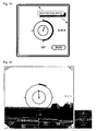
- Fig. 7 illustrates the principle of an altitude indicator, also referred to as AGL indicator below, for displaying the current altitude above ground in combination with the above-described elements of the hover layer as a centrally arranged display symbolism.
- This ring acts as an AGL indicator.
- the AGL indicator begins and ends at the so-called 12 o'clock mark of the hover layer, ie the 12 o'clock mark corresponds to both the maximum value mark and the minimum value mark of the AGL indicator.
- the AGL indicator appears in addition to the hover-layer imagery described above, preferably above a suitable minimum helicopter altitude above ground (e.g., 100 ft. AGL). This minimum height corresponds to the maximum value that can be displayed using the altitude indicator. At the minimum height, the AGL indicator has the shape of a closed circle.
- its display area can be set to less than 360 degrees, e.g. on a semicircle, so that the heights between minimum height and height 0 ft are shown in the angle range between 0 and 180 degrees. In such an embodiment, when reaching the minimum height, a semicircle would be displayed.
- the big advantage of the AGL indicator which changes in height over ground, is that it adapts to the outer speed circle of the drift indicator. This allows the pilot to keep an eye on both displays - drift indicator and altitude indicator.
- This solution has compared to other display concepts - especially on and decaying bar displays, as for example in the above WO 2005/015333 A2 the advantage is that the pilot's gaze and attention do not have to shift from the center of the MMI to the edge of the screen, or switch back and forth, in order to provide the key parameters for controlling the helicopter Brown-Out case to read.
- a flight under brown-out conditions requires a very high concentration by the pilot in the case of a completely or partially restricted cockpit external view. However, a very high concentration can lead to a so-called "tunnel view" in humans.
- the essential parameters are arranged centrally and can be detected at a glance.
- Fig. 8 shows a concrete graphical realization of the hover layer with the described symbolism, which is superimposed on the 3D scene layer.
- the hover layer may contain a wide variety of additional alphanumeric and / or graphical displays. Which additional ads are included in this layer can be adapted to the particular purpose of a specific helicopter pattern.
- the numeric display of the current heading angle and the numerical display of the current altitude above ground (AGL altitude). Since the altitude above ground in aviation is often referred to as radar altitude, the corresponding numeric display, for example, an "R" be preceded to avoid confusion with other ads. Importantly, the numerical display of the AGL altitude has an exact correspondence of the arc length of the graphical AGL indicator described above in the form of a variable length circular arc. Such an embodiment shows in a schematic representation of the Fig. 9 ,
- Brown-Out MMI Another advantageous addition to the Brown-Out MMI is, for example, the display of the current pitch angle of the helicopter. This can be done (a) numerically - as in Fig. 10 shown - and / or (b) graphically by displaying a so-called pitch ladder. It should be noted, however, that the pitch and roll angles of the helicopter are already very well estimated by the combination of the base and 3D scene layers, so that in many cases this additional display can be dispensed with to the display to restrict to the absolutely necessary elements.
- Fig. 10 shows a concrete graphical realization of the MMI invention from the superposition of base layer, 3D scene layer and extended hover layer.
- the display includes the numerical representation of the current heading angle preceded by the north direction indicator.
- the numerical representation of the AGL altitude As well as the current pitch angle (pitch).
- the graphic on the right also shows the corresponding attitude again.
- an additional graphics layer may advantageously be present in the brown-out MMI according to the invention. It is used to identify a brown-out condition. If the helicopter is in Brown Out, this may be indicated by (a) appropriate lettering and / or (b) a distinctive icon. In the execution after Fig. 11 For example, the outlined lettering BOUT is displayed at the bottom right of the display. Alternatively or additionally, further graphical elements may be used for better identification of a brown-out state, for example an additional frame at the edge of the display, as also in FIG Fig. 11 shown as an example. The lettering and the frame can also be flashing during their activation.
Abstract
Description
Die Erfindung betrifft ein Mensch-Maschinen-Interface (MMI) zur Pilotenunterstützung bei Start und Landung eines Fluggeräts, insbesondere eines Helikopters bei verminderter Außensicht oder unter eingeschränkten Sichtbedingungen. In trockenen, wüstenartigen Gebieten (wie z.B. Afghanistan) kommt es bei fast jeder Außenlandung von Hubschraubern zu einer starken Aufwirbelung von Sand und Staub. Dies wird durch den sog. Down-Wash des Hauptrotors verursacht. Die Sand- bzw. Staubaufwirbelung führt oft dazu, dass der Pilot die Cockpit-Außensicht ganz oder teilweise verliert - dem so genannten Brown-Out. Durch den Verlust der Außensicht besteht für den Piloten die Gefahr des Verlustes der räumlichen Orientierung und dies insbesondere hinsichtlich Nick- und/oder Rollwinkel sowie ungewollter seitlicher Drift des Luftfahrzeugs.The invention relates to a human-machine interface (MMI) for pilot support during take-off and landing of an aircraft, in particular a helicopter in a reduced external view or in restricted visibility conditions. In arid, desert-like areas (such as Afghanistan), almost every helicopter landing is a major source of sand and dust. This is caused by the so-called down-wash of the main rotor. The sand or Staubaufwirbelung often causes the pilot loses the cockpit outside view in whole or in part - the so-called brown-out. Due to the loss of the external view, the pilot is at risk of losing the spatial orientation and this in particular with regard to pitch and / or roll angle as well as unwanted lateral drift of the aircraft.
Der Kern einer für Brown-Out geeigneten Hubschrauberlandehilfe (Brown-Out-Recovery-System) ist dessen MMI als Schnittstelle zwischen Mensch und Maschine. Die operationelle Einsatztauglichkeit, hängt dabei entscheidend von der Brauchbarkeit einer entsprechenden Display-Anzeige ab. Gründe hierfür sind:
- a) die grundsätzliche aero-dynamische Instabilität eines Hubschraubers (speziell beim sog. Schwebe- oder Hover-Flug),
- b) die oft unkalkulierbaren Einflusses von Windböen, Turbolenzen und Scherwinden im Landeendanflug (oder beim Start),
- c) das bei Außenlandungen oft völlig unbekannte Gelände sowie die Hindernissituation am Landeplatz insbesondere im Hinblick auf Abspanndrähte und Stromleitungen,
- d) die bei militärischen und SAR-Einsätzen sich möglicherweise sehr schnell ändernde Situation am Landeplatz,
- e) die momentane Messgenauigkeit einsatztauglicher Fluglagereferenz- und Distanzmeßsysteme,
- f) die Möglichkeit der flexiblen Reaktion und eventuell notwendiger Korrekturen des Piloten und
- g) die Frage der Luftfahrtzulassung.
- a) the basic aero-dynamic instability of a helicopter (especially in the so-called hover or hover flight),
- b) the often incalculable influence of gusts of wind, turbulences and shear winds in landing approach (or take-off),
- c) the terrain, which is often completely unknown during outdoor landings, as well as the obstacle situation at the landing site, in particular with regard to guying wires and power lines,
- d) the situation at the landing site, which may change very rapidly during military and SAR missions,
- (e) the instantaneous measurement accuracy of operational flight attitude reference and distance measurement systems;
- f) the possibility of the flexible response and any necessary corrections by the pilot and
- g) the issue of aviation approval.
Diese Gründe lassen es kurz- bis mittelfristig als unwahrscheinlich erscheinen, dass eine Außenlandung unter Brown-Out Bedingungen vollständig autonom auf Basis eines vollautomatischen Landesystems möglich sein wird. Man muss vielmehr davon ausgehen, dass es nach wie vor der Pilot sein wird, der im Brown-Out Fall den Hubschrauber landet. Somit erscheint nur eine visuelle Display-Anzeige als geeignet, dem Piloten bei einer Brown-Out Landung wirkungsvoll sowie unmittelbar zu unterstützen.These reasons make it unlikely in the short to medium term that an outward landing under brown-out conditions will be completely autonomous on the basis of a fully automatic landing system. Rather, one has to assume that it will still be the pilot who lands the helicopter in the Brown-Out case. Thus, only a visual display display appears to be effective in assisting the pilot in a brown-out landing effectively and directly.
In der
In der
Es ist Aufgabe der Erfindung, eine Mensch-Maschinen-Schnittstelle zu schaffen, um dem Piloten bei einer Brown-Out Landung eine optimierte intuitive Unterstützung bei der räumlichen Orientierung ermöglicht.It is an object of the invention to provide a man-machine interface to allow the pilot in a brown-out landing optimized intuitive support in the spatial orientation.
Diese Aufgabe wird mit dem Gegenstand des Patentanspruchs gelöst. Vorteilhafte Ausführungen der Erfindung sind Gegenstand von Unteransprüchen.This object is achieved with the subject of the claim. Advantageous embodiments of the invention are the subject of dependent claims.
Mit dem erfindungsgemäßen Brown-Out MMI werden auf einem einzigen Display die entscheidenden Kenngrößen zur visuellen Einschätzung der Lage und Bewegung des Fluggeräts (im folgenden wird beispielhaft von einem Hubschraubers ausgegangen) im Raum graphisch zu einem Brown-Out MMI kombiniert:
- 1. die natürliche Außenansicht - also die Gesamtheit aller Hindernisse (Leitungen und Drähte) und aller natürlichen sowie künstlichen Objekte (Gebäude, Bäume und Büsche ...) und aller topographischen Gegebenheiten inklusive des Erdbodens in der näheren Umgebung des Landeplatzes,
- 2. die Kenntnis der momentanen Fluglage, Bewegungsrichtung und Geschwindigkeit des Luftfahrzeugs über Grund sowie deren Änderung und in vorteilhaften Ausführungen deren Änderungsgeschwindigkeit,
- 3. die Kenntnis der momentanen Flughöhe über Grund (AGL) sowie in vorteilhaften Ausführungen deren Änderungstendenz.
- 1. the natural external view - ie the totality of all obstacles (wires and lines) and all natural and artificial objects (buildings, trees and shrubs ...) and all topographic conditions including the soil in the vicinity of the landing site,
- 2. the knowledge of the current attitude, direction of movement and speed of the aircraft over ground and their change and, in advantageous embodiments, their rate of change,
- 3. The knowledge of the current altitude above ground (AGL) and in advantageous embodiments whose tendency to change.
Damit werden dem Piloten alle für eine Brown-Out Landung notwendigen Informationen konzentriert auf nur ein einziges Anzeigegerät visuell dargestellt, so dass es möglich ist, allein auf Basis des erfindungsgemäßen Brown-Out MMI den Hubschrauber in einer intuitiven Weise zu landen.Thus, the pilot is visually displayed all the information necessary for a brown-out landing on a single display device, so that it is possible to land the helicopter in an intuitive manner based solely on the Brown-Out MMI invention.
Das erfindungsgemäße Brown-Out MMI besteht aus mehreren, übereinander dargestellten Graphik-Layern, um den Kriterien zur Lage- und Bewegungskontrolle in geeigneter Art und Weise Rechnung zu tragen. Jeder dieser Layer enthält jeweils gewisse Graphikprimitive und Symbolik, welche in summa das vollständige Brown-Out MMI definieren.The brown-out MMI according to the invention consists of a plurality of graphics layers, shown one above the other, in order to suit the criteria for position and movement control in a suitable manner. Each of these layers contains certain graphic primitives and symbols, which in total define the complete Brown-Out MMI.
Folgende Graphik-Layer sind in dem erfindungsgemäßen Brown-Out MMI übereinander dargestellt:
- a) Ein Basis-Layer in Form einer ebenen Basisfläche. Diese Basisfläche symbolisiert eine idealisierte Bodenfläche, berechnet nur aufgrund des momentanen Wertes der Flughöhe über Grund und der momentanen Fluglagedaten (Rollwinkel, Nickwinkel, Kurswinkel). Die reale dreidimensionale Topologie des Bodens geht also hier nicht ein. Diese wird vielmehr durch den 3D-Szenen-Layer erfasst. Die Basisfläche wird durch einen künstlichen Horizont begrenzt und wird mit den momentanen Flugzustandsdaten und der momentanen Höhe über Grund fortlaufend aktualisiert. Insgesamt veranschaulicht der Basis-Layer qualitativ in einer für den Piloten sehr leicht nachvollziehbaren Weise Fluglage und Flughöhe des Fluggeräts im Raum. Sie dient dem Piloten zur verbesserten räumlichen Orientierung in der kritischen Phase des Brown-Out, während der häufig Sand- und Staubpartikel in chaotischer Verwirbelung schräg an den Cockpitfenstern vorbeiströmen und die räumliche Orientierung erschweren.
- b) Ein 3D-Szenen-Layer, der ein dreidimensionales positionsgenaues sowie zeitlich korrektes (d.h. in Echtzeit) Abbild der realen Szenerie in Richtung des Flugpfads des Hubschraubers darstellt, und der mit den momentanen Flugzustandsdaten und der momentanen Höhe über Grund fortlaufend aktualisiert wird. Der 3D-Szenen-Layer dient insbesondere zur räumlichen Orientierung des Piloten bei völligem oder teilweisem Fehlen der Cockpit-Außensicht. Die Darstellung des 3D-Szenen-Layers besteht aus 3D-Daten der Umgebung des Landeplatzes, d.h. anders als bei einem herkömmlichen 2-dimensionalen, projektiven Abbild der Umgebung sind für jeden Bildpunkt des 3D-Szenen-Layers die Koordinaten in 3 räumlichen Dimensionen bekannt. Die Darstellung der 3D-Szene kann z.B. derart erfolgen, dass die Entfernung von Objekten oder Hindernissen zum Fluggerät durch unterschiedliche Farben oder Grauwerte codiert wird. Eine andere Möglichkeit ist die Codierung auf der Basis der Höhe über Grund des betreffenden Bildpunkts oder einer Kombination aus Entfernung und Objekthöhe.
- c) Ein Schwebeflug-Layer zur kombinierten Darstellung der Geschwindigkeit über Grund, der Richtung der momentanen Bewegungs- oder Driftrichtung in Relation zur Hubschrauber-Längsachse sowie der Flughöhe über Grund. Der Schwebeflug-Layer kann in weiteren Ausführungen zusätzliche Informationen als Unterstützung für den Piloten zur Einschätzung des Flugzustands enthalten, z.B. die numerische Anzeige des Kurswinkels oder der momentanen Höhe über Grund sowie eine Nickwinkelanzeige (graphisch bzw. alphanumerisch).
- a) A base layer in the form of a flat base surface. This base area symbolizes an idealized floor area, calculated only on the basis of the current value of the altitude over ground and the current position data (roll angle, pitch angle, heading angle). The real three-dimensional topology of the soil is therefore not included here. This is captured by the 3D scene layer. The base area is bounded by an artificial horizon and is continuously updated with the current flight condition data and the current altitude over ground. Overall, the base layer qualitatively illustrates the attitude and altitude of the aircraft in space in a manner very readily traceable to the pilot. It serves the pilot for improved spatial orientation in the critical phase of the Brown-Out, while the sand and dust particles in chaotic turbulence often flow obliquely past the cockpit windows and make the spatial orientation more difficult.
- b) A 3D scene layer representing a three-dimensional, accurate and timely (ie real-time) image of the real scene in the direction of the helicopter's flight path, which is continuously updated with the current flight condition data and the current altitude over ground. The 3D scene layer serves in particular for the spatial orientation of the pilot in the case of complete or partial absence of the cockpit external view. The representation of the 3D scene layer consists of 3D data of the surroundings of the landing site, ie unlike a conventional 2-dimensional, projective image of the environment, the coordinates in 3 spatial dimensions are known for each pixel of the 3D scene layer. The representation of the 3D scene can for example be such that the distance of objects or obstacles to the aircraft is coded by different colors or gray values. Another possibility is encoding based on the elevation above ground of the pixel in question or a combination of distance and object height.
- c) A hover layer for the combined display of speed over ground, the direction of the current direction of movement or drift in relation to the helicopter longitudinal axis and the altitude above ground. The hover layer, in other implementations, may include additional information to assist the pilot in assessing the flight condition, eg, the numeric display the heading angle or the current altitude above ground and a pitch angle display (graphical or alphanumeric).
Wesentlich für die Erfindung ist, dass sich alle Layer des erfindungsgemäßen Brown-Out MMI's mit ihren jeweiligen Informationen gegenseitig stützen und ergänzen. Ein einziger Layer für sich genommen ist nicht in der Lage, dem Piloten ein einsatztaugliches Brown-Out MMI an die Hand zu geben. Erst die Kombination aller oben beschriebenen MMI-Komponenten ermöglicht den operationellen Einsatz und ist damit in der Lage, eine substantielle Hilfe und Unterstützung im Brown-Out Fall zu sein.It is essential to the invention that all layers of the Brown-Out MMI according to the invention mutually support and supplement each other with their respective information. A single layer alone is not able to give the pilot an out-of-the-box Brown-Out MMI. Only the combination of all of the above-described MMI components enables operational deployment and is thus able to provide substantial help and support in the brown-out case.
Zusätzlich zu den genannten Graphik-Layern können in dem erfindungsgemäßen MMI graphische oder alphanumerische Zeichen dargestellt werden, die das Vorhandensein eines Brown-Out Zustands kennzeichnen. Die Gesamtheit derartiger Zeichen wird im Folgenden als BOUT-Layer bezeichnet. Dieser Layer weist den Piloten insbesondere auf die Funktionsfähigkeit des dem MMI übergeordneten Brown-Out-Recovery-Systems im Falle eines teilweisen oder vollständigen Verlusts der Cockpit-Außensicht hin.In addition to the graphic layers mentioned, graphic or alphanumeric characters which characterize the presence of a brown-out state can be displayed in the MMI according to the invention. The totality of such characters is referred to below as a BOUT layer. In particular, this layer informs the pilot of the functionality of the MMI superior Brown Out Recovery System in the event of a partial or complete loss of the cockpit external view.
Im Brown-Out Zustand ist die Cockpit-Außensicht teilweise oder vollständig durch aufgewirbelten Sand und Staub verdeckt. Wie ein dem Brown-Out MMI übergeordnetes Brown-Out Recovery System einen solchen Zustand erkennt (manuell durch eine Pilotenaktion oder automatisch) und wie die 3D-Szenendaten während des Brown-Outs verwaltet werden (Darstellung aus einer zuvor akkumulierter History/Datenbank, automatisches, algorithmisches Filtern der Staubdaten oder sensortechnisches "Hindurchsehen" durch die Wolke) ist für das erfindungsgemäße MMI ohne Belang, d.h. das Brown-Out MMI funktioniert in all diesen Konstellationen in gleicher Art und Weise.In the brown-out state, the cockpit exterior view is partially or completely obscured by swirling sand and dust. How a Brown-Out Recovery System superordinate to the Brown-Out MMI recognizes such a condition (manually by a pilot action or automatically) and how the 3D scene data is managed during the Brown-Out (representation from a previously accumulated history / database, automatic, algorithmic filtering of the dust data or sensor technology "look through" by the cloud) is irrelevant for the MMI according to the invention, ie The Brown-Out MMI works the same way in all these constellations.
Die erfindungsgemäße MMI kann universell unter operationellen Bedingungen eingesetzt werden. Es ermöglicht eine intuitive Unterstützung des Piloten bei der räumlichen Orientierung während der Landung speziell unter Brown-Out Bedingungen. Für das erfindungsgemäße Brown-Out MMI ist lediglich ein einziges Display (z.B. Multifunktionsdisplay MFD, ein Head-Up-Display HUD, ein Helmet-Mounted-Display HMD) im Cockpit notwendig. Deshalb kann die vorliegende Erfindung in jedem Brown-Out Recovery System, welches auf dem Prinzip einer visuellen Orientierungshilfe beruht, zum Einsatz kommen.The MMI according to the invention can be used universally under operational conditions. It provides intuitive pilot assistance in spatial orientation during landing, especially under brown-out conditions. For the Brown-Out MMI according to the invention, only a single display (eg multifunction display MFD, a head-up display HUD, a helmet-mounted display HMD) in the cockpit is necessary. Therefore, the present invention can be found in Any brown-out recovery system based on the principle of visual guidance.
Ein weiterer Vorteil der vorliegenden Erfindung ist, dass das erfindungsgemäße MMI auch zur Pilotenunterstützung unter so genannten White-Out Bedingungen anwendbar ist, bei denen durch Aufwirbelung von losen Schnee- und Eiskristallen eine ähnlich kritische Situation wie beim Brown-Out besteht.A further advantage of the present invention is that the MMI according to the invention is also applicable to pilot support under so-called white-out conditions in which a similar critical situation exists as with brown-out due to the swirling up of loose snow and ice crystals.
Nachfolgend werden konkrete Ausführungen der Graphik-Layer unter Bezugnahme auf Figuren im Einzelnen beschrieben. Es zeigen:
- Fig. 1
- eine Ausführung des Basis-Layers (Prinzipdarstellung),
- Fig. 2
- eine konkrete graphische Realisierung des Basis-Layers; die korrespondierende, aktuelle Fluglage ist zum Vergleich rechts unten zusätzlich dargestellt,
- Fig. 3
- eine Ausführung der 3D-Bodenfläche als Bestandteil des 3D-Szenen-Layers (Prinzipdarstellung),
- Fig. 4
- eine Ausführung des 3D-Szenen-Layers mit 3D-Bodenfläche und darauf angeordneten Nicht-Bodenobjekten (Prinzipdarstellung),
- Fig. 5
- eine konkrete graphische Realisierung des 3D-Szenen-Layers mit unterlegtem Basislayer,
- Fig. 6
- eine Ausführung des Schwebeflug-Layers (Prinzipdarstellung), wobei der Höhenindikator aus Gründen der Übersichtlichkeit weggelassen wurde,
- Fig. 7
- eine Ausführung des Schwebeflug-Layers (Prinzipdarstellung),
- Fig. 8
- eine konkrete graphische Realisierung des 3D-Szenen-Layers mit überlagertem Schwebeflug-Layer,
- Fig. 9
- eine weitere Ausführung des Schwebeflug-Layers mit der Anzeige zusätzlicher Informationen wie der numerischen Darstellung von Kurswinkel sowie der Höhe über Grund (Prinzipdarstellung),
- Fig. 10
- eine konkrete graphische Realisierung der Überlagerung von Basis-Layer, 3D-Szenen-Layer und Schwebeflug-Layer,
- Fig. 11
- eine Ausführung des Schwebeflug-Layers mit zusätzlichem Bout-Layer, der das Vorhandensein eines Brown-Out Zustands anzeigt (Prinzipdarstellung),
- Fig. 12
- eine konkrete graphische Realisierung der Überlagerung von Basis-Layer, 3D-Szenen-Layer, Schwebeflug-Layer und Bout-Layer.
- Fig. 1
- an execution of the base layer (schematic diagram),
- Fig. 2
- a concrete graphical realization of the base layer; the corresponding, current attitude is shown in addition to the lower right,
- Fig. 3
- an execution of the 3D floor surface as part of the 3D scene layer (schematic diagram),
- Fig. 4
- an embodiment of the 3D scene layer with 3D floor surface and non-floor objects arranged thereon (schematic representation),
- Fig. 5
- a concrete graphical realization of the 3D scene layer with underlying base layer,
- Fig. 6
- an embodiment of the hover layer (schematic diagram), wherein the height indicator has been omitted for reasons of clarity,
- Fig. 7
- an execution of the hover layer (schematic diagram),
- Fig. 8
- a concrete graphical realization of the 3D scene layer with superimposed hover layer,
- Fig. 9
- a further execution of the hover layer with the display of additional information such as the numerical representation of the course angle and the height above ground (schematic diagram),
- Fig. 10
- a concrete graphical realization of the overlay of base layer, 3D scene layer and hover layer,
- Fig. 11
- an execution of the hover layer with an additional bout layer, which indicates the presence of a brown-out state (schematic diagram),
- Fig. 12
- a concrete graphical realization of the overlay of base layer, 3D scene layer, hover layer and bout layer.
Alle graphischen Elemente des Basis-Layers werden mit Hilfe der momentanen Flugzustandsdaten (Fluglage) sowie der aktuellen Höhe über Grund (AGL) aktualisiert. Damit wird sichergestellt, dass alle Änderungen von Fluglage und Höhe über Grund unmittelbar eine entsprechende Änderung in der Graphik-Anzeige des Basis-Layers nach sich ziehen.All graphical elements of the base layer are updated using the current flight state data (attitude) and the current altitude above ground (AGL). This ensures that any changes in attitude and altitude over ground will immediately cause a corresponding change in the graphics display of the base layer.
Der räumliche Eindruck - insbesondere bezüglich der Abschätzung der Flughöhe über Grund - kann nochmals erhöht werden, wenn die Basisfläche ganz bzw. teilweise mit einem Schachbrettmuster oder einer graphischen Bodentextur oder beidem belegt wird. Ein Beispiel für eine konkrete Realisierung eines solchen Basis-Layers ist in
Der 3D-Szenen-Layer liegt über dem Basis-Layer. Er stellt ein positionsgenaues Abbild der realen 3-dimensionalen Welt in Richtung des Flugpfades des Hubschraubers dar. Positionsgenau bedeutet dabei, dass die dargestellten relativen Ortsunterschiede zwischen dem Flugobjekt und den Objekten der Umgebung der Wirklichkeit entsprechen.The 3D scene layer is above the base layer. It represents a positionally accurate image of the real 3-dimensional world in the direction of the flight path of the helicopter. Positional means that the relative location differences shown between the flying object and the objects of the environment correspond to reality.
Der 3D-Szenen-Layer kann grob in zwei Bestandteile zerlegt werden:
- a) eine 3D-Bodenfläche als Approximation der lokalen Topographie des Erdbodens, wie z.B. in
Fig. 3 dargestellt. - b) die Abbildung der Nicht-Bodenobjekte oberhalb der 3D-Bodenfläche (
Fig. 4 ).
- a) a 3D floor surface as an approximation of the local topography of the soil, such as in
Fig. 3 shown. - b) the image of non-ground objects above the 3D floor surface (
Fig. 4 ).
Auf der approximierten 3D-Bodenfläche können Flucht und Distanzlinien vorhanden sein, wie in
Die Nicht-Bodenobjekte können numerisch analysiert werden, um alle oder nur bestimmte Typen dieser Nicht-Bodenobjekte (z.B. Leitungen, Abspanndrähte und Masten) im 3D-Szenen-Layer graphisch hervorzuheben. Die numerische Analyse geschieht durch Segmentierung, d.h. die Objekte als solche werden vom Boden getrennt, und/oder Klassifizierung nach vorgegebenen Objekt- bzw. Hindernistypen. Eine solche Erweiterung des Brown-Out MMI's verbessert die räumliche Orientierung zusätzlich und warnt den Piloten vor gefährlichen Hindernissen im Flugpfad.The non-ground objects can be numerically analyzed to graphically highlight all or only certain types of these non-ground objects (e.g., lines, guy wires and masts) in the 3D scene layer. The numerical analysis is done by segmentation, i. the objects as such are separated from the ground, and / or classification according to predetermined object or obstacle types. Such an extension of the Brown-Out MMI further improves the spatial orientation and warns the pilot of dangerous obstacles in the flight path.
In einer vorteilhaften Ausführung werden alle oder einzelne der segmentierten bzw. klassifizierten Nicht-Bodenobjekte mit einem graphischem Muster oder einer Objekttextur vollständig oder teilweise belegt.In an advantageous embodiment, all or some of the segmented or classified non-ground objects are completely or partially occupied with a graphic pattern or an object texture.
Zusätzlich können die approximierte 3D-Bodenfläche und/oder die segmentierten bzw. klassifizierten Nicht-Bodenobjekte vollständig oder teilweise durch graphische Bildverbesserung in Form von künstlichem Schattenwurf oder Selbst-Illumination gesondert hervorgehoben werden.In addition, the approximated 3D bottom surface and / or the segmented or classified non-ground objects may be fully or partially highlighted by graphical image enhancement in the form of artificial shadowing or self-illumination.
Alle graphischen Elemente des 3D-Szenen-Layers werden mit Hilfe der momentanen Flugzustandsdaten (Fluglage und -geschwindigkeit) sowie der aktuellen Höhe über Grund (AGL) aktualisiert. Damit wird sichergestellt, dass alle Änderungen von Fluglage, Fluggeschwindigkeit und Höhe über Grund unmittelbar und ohne merkbare zeitliche Verzögerung eine entsprechende Änderung in der Graphik-Anzeige des 3D-Szenen-Layers nach sich ziehen. Es entsteht eine Art "Virtual-Reality" Eindruck.All graphical elements of the 3D scene layer are updated using the current flight state data (attitude and velocity) and the current altitude above ground (AGL). This ensures that any changes in attitude, airspeed, and elevation above ground will immediately cause a corresponding change in the graphics display of the 3D scene layer without noticeable time delay. It creates a kind of "virtual reality" impression.
Für die räumliche Orientierung des Piloten und die Kontrolle des Hubschraubers im Brown-Out Fall spielt der 3D-Szenen-Layer eine sehr wichtige Rolle. Faktisch ersetzt dieser Layer für den Piloten die fehlende Cockpit-Außensicht. Hierbei sind drei Dinge von Bedeutung:
- (1) eine genaue Approximation der Erdoberfläche durch die 3D-Bodenfläche,
- (2) die größtmögliche Vollständigkeit bez. der Darstellung aller für eine problemlose räumliche Orientierung notwendigen Nicht-Bodenobjekte,
- (3) die 3-Dimensionalität sowohl der Bodenfläche als auch aller dargestellten Nicht-Bodenobjekte.
- (1) a precise approximation of the earth's surface through the 3D bottom surface,
- (2) the greatest possible completeness. the representation of all non-ground objects necessary for a problem-free spatial orientation,
- (3) the 3-dimensionality of both the floor surface and all non-floor objects presented.
Die Bedeutung der 3-Dimensionalität der Bodenfläche und der Nicht-Bodenobjekte liegt in der Tatsache begründet, dass der Pilot im Brown-Out Fall bis zu 30s und mehr durch die virtuelle Szenerie des 3D-Szenen-Layers fliegen muss, bevor der Hubschrauber am Boden aufsetzt. Darüber hinaus können gefährliche Fluglagesowie Positionsänderungen während der Brown-Out Landung nur dann schnell und korrekt erkannt werden, wenn Höhe, Ausdehnung, Position und Orientierung aller Objekte oder Hindernisse in Relation zum Hubschrauber zu jedem Zeitpunkt korrekt angezeigt werden - einschließlich der momentanen Höhe über Grund. Das geometrisch sowie zeitlich korrekte Nachführen (Translation und Rotation) der 3D-Objekte auf der Projektionsebene des 3D-Szenen-Layers während einer Brown-Out Landung erfolgt unter Zuhilfenahme der momentanen Flugzustandsdaten (Fluglage und Geschwindigkeit) aus denen alle relativen Orts- sowie Orientierungsänderungen abgeleitet werden können.The importance of 3-dimensionality of ground surface and non-ground objects is due to the fact that in the Brown-Out case the pilot must fly up to 30s and more through the virtual scenery of the 3D scene layer before the helicopter hits the ground touches down. In addition, dangerous flight positions and position changes during the Brown-Out landing can only be detected quickly and correctly if the height, extent, position and orientation of all objects or obstacles in relation to the helicopter are displayed correctly at all times - including the current altitude above ground. The geometrically and temporally correct tracking (translation and rotation) of the 3D objects on the projection plane of the 3D scene layer during a Brown-Out landing takes place with the aid of the current flight state data (attitude and attitude) Speed) from which all relative location and orientation changes can be derived.
Die 3D-Informationen für die Bodenfläche und für die Nicht-Bodenobjekte können entweder von einem RADAR, einem Ultraschall-System, einem laserbasierten LADAR oder anderen geeigneten, aktiv messenden Systemen stammen oder mittels Stereoskopie (numerische Tiefenberechnung aus zwei oder mehreren Bildern) errechnet werden.The ground and non-ground 3D information can be from either a RADAR, an ultrasound system, a laser-based LADAR, or other suitable active measuring system, or can be calculated by stereoscopy (numerical depth calculation from two or more images).
Als 3D-Sensor wird bevorzugt ein entfernungsbildgebender Sensor, insbesondere ein abbildendes Laserradar eingesetzt, wie es z.B. in der
Für die Ermittlung der Flugzustandsdaten (Fluglage und -geschwindigkeit) vor und während einer Brown-Out Situation existieren eine große Menge an geeigneten Lagereferenz- und Navigationsanlagen (z.B. von den Firmen Aerodata Flugmesstechnik GmbH oder Honeywell International Inc.). In Abhängigkeit von der Messgenauigkeit solcher Lagereferenz- und Navigationssysteme kann die Höhe über Grund entweder aus den gemessenen Geschwindigkeitsvektor-Komponenten numerisch berechnet werden oder die AGL-Höhe wird ebenfalls über RADAR, LADAR, Ultraschall etc. gemessen. Zur Ermittlung des momentanen Flugzustandes und/oder der Höhe über Grund können auch geeignete Verfahren aus der digitalen Bildverarbeitung angewandt werden, mit deren Hilfe die Lage und Bewegung des Hubschraubers an Hand des sog. optischen Flusses basierend auf einer Bildfolgenanalyse berechnet wird.For determining the flight condition data (attitude and speed) before and during a brown-out situation, there is a large amount of suitable attitude reference and navigation equipment (e.g., Aerodata Flugmesstechnik GmbH or Honeywell International Inc.). Depending on the measurement accuracy of such position reference and navigation systems, the altitude over ground can either be calculated numerically from the measured velocity vector components or the AGL altitude is also measured via RADAR, LADAR, ultrasound, etc. In order to determine the instantaneous flight status and / or the altitude above ground, it is also possible to use suitable methods from digital image processing, with the aid of which the position and movement of the helicopter is calculated on the basis of a so-called optical flow based on an image sequence analysis.
Die 3D-Informationen des 3D-Szenen-Layers für die Bodenfläche und für die Nicht-Bodenobjekte können (a) bis unmittelbar vor dem Brown-Out Zustand akkumuliert und in einem übergeordneten Brown-Out Recovery System zwischengespeichert werden, bevor sie im 3D-Szenen-Layers während des Brown-Outs zur Anzeige gebracht werden oder (b) von einem Sensorsystem erfasst werden, welches vollständig oder teilweise durch die sog. Brown-Out-Walze aus Sand oder Staub hindurch dringt.The 3D information of the 3D scene layer for the ground surface and for the non-ground objects can be accumulated (a) until just prior to the brown-out state and cached in a parent Brown-Out Recovery System before being used in 3D scenes -Layers during the Brown-Out to the ad or (b) be detected by a sensor system which penetrates completely or partially through the so-called brown-out roll of sand or dust.
Da die 3D-Informationen über die Nicht-Bodenobjekte in erster Linie zur räumlichen Orientierung sowie zur Abschätzung von Fluglage und Höhe über Grund dienen, ist es nicht zwingend erforderlich, dass die nichteinsehbaren Rückseiten dieser Objekte vollständig und korrekt rekonstruiert werden. Das heißt, bei den Rückseiten sind vereinfachende Annahmen über die tatsächliche Geometrie dieser Objekte zulässig. Diese Vereinfachungen auf den Objektrückseiten führen nicht zu einem Orientierungsverlust, da in erster Linie die Erhabenheit der Objekte über der Bodenfläche, ihre prinzipielle geometrische Form sowie insbesondere ihre korrekte Position in Relation zum Hubschrauber die entschiedenen Kenngrößen darstellen.Since the 3D information about the non-ground objects is primarily used for spatial orientation and for estimating the attitude and altitude above ground, it is not mandatory that the non-visible backs of these objects are completely and correctly reconstructed. That is, the backsets allow simplifying assumptions about the actual geometry of these objects. These simplifications on the backs of the objects do not lead to a loss of orientation, since primarily the majesty of the objects above the floor surface, their basic geometric shape and in particular their correct position in relation to the helicopter represent the decisive parameters.
Ebenso muss die Geometrie der Nicht-Bodenobjekte auch auf deren sichtbaren Vorderseiten nur bis zu einem gewissen Detailgrad rekonstruiert werden. Es ist durchaus hinreichend, nur die generelle geometrische Struktur und die wichtigsten räumlichen Abmessungen der Nicht-Bodenobjekte bei der Darstellung im 3D-Szenen-Layer zu berücksichtigen. Dies beeinträchtigt Lage und Orientierungsvermögen des Betrachters nicht. Unter Abwägung des notwendigen Hardware-Aufwands und der benötigten Verarbeitungszeit sollte jedoch eine möglichst feine und genaue Rekonstruktion der Objektgeometrie bei der Darstellung des 3D-Szenen-Layers angestrebt werden, um durch den Betrachter eine intuitive und gleichzeitig relativ genaue Abschätzung von Fluglage und Höhe zu ermöglichen.Likewise, the geometry of the non-floor objects must be reconstructed on their visible fronts only to a certain degree of detail. It is quite sufficient to consider only the general geometric structure and the most important spatial dimensions of the non-ground objects in the representation in the 3D scene layer. This does not affect the position and orientation of the viewer. However, considering the necessary hardware cost and processing time, the goal should be to fine-tune and accurately reconstruct the geometry of the object when displaying the 3D scene layer to allow the viewer an intuitive yet relatively accurate estimate of attitude and altitude ,
Der Basis-Layer und der 3D-Szenen-Layer ermöglichen eine räumliche Orientierung und Kontrolle der Fluglage sowie Abschätzung der Höhe über Grund im Brown-Out Fall. Der überlagerte Schwebeflug-Layer zeigt mittels einer speziellen Symbolik die Geschwindigkeit über Grund sowie die Richtung der momentane Bewegungs- oder Driftrichtung in Relation zur Hubschrauber-Längsachse an.The base layer and the 3D scene layer allow spatial orientation and control of the attitude as well as estimation of the height above ground in the Brown-Out case. The superimposed hover layer uses a special symbol to show the speed over ground and the direction of the current direction of movement or drift in relation to the helicopter's longitudinal axis.
Der Schwebeflug-Layer (
An der sog. 12 Uhr Position des äußeren Kreises befindet sich eine zusätzliche Strichmarke. Diese Marke bezeichnet die Vorausrichtung der Hubschrauber-Längsachse. Diametral dazu auf der 6 Uhr Position befindet sich eine entsprechende Marke, welche bezogen auf die Hubschrauber-Längsachse die Achterausrichtung bezeichnet. Analog gilt dies für die entsprechenden Marken an der 3 Uhr bzw. 9 Uhr Position zur Bezeichnung der Steuerbordquerab- bzw. Backbordquerab-Richtung des Hubschraubers.At the so-called 12 o'clock position of the outer circle there is an additional bar mark. This mark indicates the advance direction of the helicopter longitudinal axis. Diametrically to the 6 o'clock position is a corresponding mark, which refers to the achterausrichtung relative to the helicopter longitudinal axis. Similarly, this applies to the corresponding brands at the 3 o'clock or 9 o'clock position to designate the starboard aileron or port of the helicopter.
Der Drift-Indikator ist beweglich und "wandert" über das Display des Schwebeflug-Layers. Die momentane Position des Drift-Indikators gibt zu jeder Zeit die momentane Geschwindigkeit des Hubschraubers über Grund als auch die momentane Drift-Richtung in Relation zur Hubschrauber-Längsachse an. Die momentane Geschwindigkeit über Grund ist ein Maß für die euklidische Distanz des Drift-Indikators von der oben beschriebenen Null-Markierung im Zentrum des Schwebeflug-Layers. Die momentane Drift-Richtung in Relation zur Hubschauber-Längsachse wird durch das virtuelle Gummiband zwischen der Null-Markierung und dem Drift-Indikator angezeigt. Driftet der Hubschrauber z.B. genau nach Steuerbord querab mit einer Geschwindigkeit über Grund von 10 kn, so würde der Drift-Indikator exakt auf dem äußeren Geschwindigkeitskreis an der 3 Uhr Strichmarke zu liegen kommen.The drift indicator is mobile and "wanders" over the hover layer display. The instantaneous position of the drift indicator indicates at all times the instantaneous speed of the helicopter over ground as well as the instantaneous drift direction in relation to the helicopter longitudinal axis. The instantaneous ground speed is a measure of the Euclidean distance of the drift indicator from the zero mark at the center of the hover layer described above. The instantaneous drift direction relative to the helicopter longitudinal axis is indicated by the virtual rubber band between the zero mark and the drift indicator. For example, if the helicopter drifts right to starboard at a speed above ground of 10 knots, the drift indicator would come to lie exactly on the outer velocity circle at the 3 o'clock mark.
Mit Hilfe des Schwebeflug-Layers hat der Pilot ein visuelles Instrument an der Hand, das es ihm erlaubt, die momentane Eigenbewegung des Hubschraubers im Brown-Out Fall hinsichtlich Geschwindigkeit und Drift-Richtung sehr genau zu kontrollieren. In Kombination mit dem oben beschriebenen Basis-Layer und dem 3D-Szenen-Layers ergibt sich ein komplexes, jedoch sehr intuitiv ablesbares MMI, welches es ermöglicht, sowohl die Orientierung und Lage des Luftfahrzeugs im Raum als auch dessen Drift zu erkennen. Die Besonderheit hierbei ist, dass innerhalb eines einzigen Anzeigegerätes (Display) die räumliche Ansicht (3D-Szenen-Layer, Basis-Layer) mit einer 2-dimensionalen Symbolik des Schwebeflug-Layers kombiniert wird.With the help of the hover layer, the pilot has a visual instrument on his hand, which allows him to control the momentary self-movement of the helicopter in the Brown-Out case in terms of speed and drift direction very precisely. In combination with the base layer and the 3D scene layer described above, this results in a complex, but very intuitive MMI, which makes it possible to detect the orientation and position of the aircraft in space as well as its drift. The special feature here is that within a single display device (display), the spatial view (3D scene layer, base layer) is combined with a 2-dimensional symbology of the hover layer.
Für ein operationell einsatztaugliches Brown-Out MMI ist zusätzlich zu den beschriebenen Anzeigekomponenten des Schwebeflug-Layers die Anzeige der Höhe über Grund (AGL) von großer Bedeutung. Hierbei ist ein ungefährer, qualitativer Schätzwert (wie er sich für den Piloten aus der Darstellung des 3D-Szenen-Layer ergibt) nicht ausreichend, sondern es ist ein möglichst exakter Wert mit einer hohen Genauigkeit von 1 - 2 ft. AGL-Höhe notwendig. Die möglichst genaue AGL-Höheninformation ist besonders für größere, schwere Hubschrauber mit Radfahrwerk von Wichtigkeit - zumal gerade diese Hubschraubertypen die größten Probleme in Brown-Out Situationen haben.For an operationally operational Brown-Out MMI, in addition to the described display components of the hover layer, the indication of the altitude above ground (AGL) is of great importance. Here an approximate, qualitative estimate (as it results for the pilot from the representation of the 3D scene layer) is not sufficient, but it is a precise value as possible with a high accuracy of 1 - 2 ft. AGL height necessary. The most accurate AGL altitude information is especially important for larger, heavy helicopters with wheel gear - especially since these types of helicopters have the biggest problems in brown-out situations.
Um auch die Information der Höhe über Grund (AGL) auf eine leicht ablesbare, intuitive Art und Weise durch die vorliegende Erfindung zu lösen, wird die Symbolik des Schwebeflug-Layers um genau ein Graphikelement zur Darstellung der momentanen AGL-Höhe erweitert.
Um den äußeren konzentrischen Geschwindigkeitskreis des Schwebeflug-Layers herum wird ein weiterer, in dieser Ausführung breiter ausgeführter Ring gezogen. Dieser Ring fungiert als AGL-Indikator. Der AGL-Indikator beginnt und endet an der so genannten 12 Uhr Strichmarke des Schwebeflug-Layers, d.h. die 12 Uhr Strichmarke entspricht sowohl der Maximalwert-Markierung als auch der Minimalwert-Markierung des AGL-Indikators.Around the outer concentric velocity circle of the hover layer another, in this embodiment, wider ring is drawn. This ring acts as an AGL indicator. The AGL indicator begins and ends at the so-called 12 o'clock mark of the hover layer, ie the 12 o'clock mark corresponds to both the maximum value mark and the minimum value mark of the AGL indicator.
Der AGL-Indikator erscheint zusätzlich zur oben beschriebenen Schwebeflug-Layer-Symbolik, bevorzugt ab einer geeigneten Mindesthöhe des Hubschraubers über Grund (z.B. 100 ft. AGL). Diese Mindesthöhe entspricht dem Maximalwert, der mit dem Höhenindikator angezeigt werden kann. Bei der Mindesthöhe hat der AGL-Indikator die Form eines geschlossenen Kreises.The AGL indicator appears in addition to the hover-layer imagery described above, preferably above a suitable minimum helicopter altitude above ground (e.g., 100 ft. AGL). This minimum height corresponds to the maximum value that can be displayed using the altitude indicator. At the minimum height, the AGL indicator has the shape of a closed circle.
Wenn der Hubschrauber sinkt und sich dadurch seine Höhe über Grund verringert, reduziert sich synchron die Bogenlänge des ringförmigen AGL-Indikators und zwar rückdrehend im Gegenuhrzeigersinn. Steigt der Hubschrauber wieder, dann nimmt analog die Bogenlänge des AGL-Indikators rechtdrehend im Uhrzeigersinn ebenfalls wieder zu. Die Bogenlänge des ringförmigen AGL-Indikators reduziert sich zu Null genau in dem Moment, in dem der Hubschrauber auf den Erdboden aufsetzt. Damit bekommt die 12 Uhr Strichmarke auf dem äußeren Kreis des Driftindikators zusätzlich die Bedeutung der 0 ft. Höhenmarke. Die zusätzliche Bedeutung der drei anderen Strichmarken (3 Uhr, 6 Uhr, 9 Uhr) ergibt sich leicht und unmittelbar aus der maximalen Anzeigehöhe für den AGL-Indikator, z.B. 3 Uhr = 25 ft., 6 Uhr = 50 ft., 9 Uhr = 75 ft., wenn die max. Anzeigehöhe bei 12 Uhr = 100 ft liegt.When the helicopter sinks and thus its height above ground is reduced synchronously, the arc length of the annular AGL indicator is reversely counterclockwise. If the helicopter rises again, then the arc length of the AGL indicator also increases clockwise in a clockwise direction. The arc length of the annular AGL indicator drops to zero just as the helicopter touches the ground. This gives the 12 o'clock mark on the outer circle of the drift indicator additionally the meaning of the 0 ft. Height mark. The additional meaning of the three other tick marks (3 o'clock, 6 o'clock, 9 o'clock) results easily and directly from the maximum display height for the AGL indicator, e.g. 3 o'clock = 25 ft., 6 o'clock = 50 ft., 9 o'clock = 75 ft., If the max. Display height is 12 o'clock = 100 feet.
In einer weiteren, hier nicht dargestellten Variante des AGL-Indikators kann sein Darstellungsbereich auf weniger als 360 Grad festgelegt werden, z.B. auf einen Halbkreis, so dass die Höhen zwischen Mindesthöhe und Höhe 0 ft im Winkelbereich zwischen 0 und 180 Grad dargestellt werden. In einer solchen Ausführung würde bei Erreichen der Mindesthöhe ein Halbkreis dargestellt.In another variant of the AGL indicator, not shown here, its display area can be set to less than 360 degrees, e.g. on a semicircle, so that the heights between minimum height and
Der große Vorteil des sich mit der Höhe über Grund ändernden AGL-Indikators liegt ganz wesentlich darin, dass er sich an den äußeren Geschwindigkeitskreis des Driftindikators anschmiegt. Dadurch ist es dem Piloten möglich, beide Anzeigen - Driftindikator und Höhenanzeige - gleichzeitig im Auge zu behalten. Diese Lösung hat gegenüber anderen Anzeigekonzepten - insbesondere an- und abschwellende Balkenanzeigen, wie sie z.B. in der oben angeführten
Der Schwebeflug-Layer kann eine große Vielzahl von zusätzlichen alphanumerischen und/oder graphischen Anzeigen enthalten. Welche zusätzlichen Anzeigen in diesen Layer aufgenommen werden, kann an den jeweiligen Einsatzzweck eines bestimmten Hubschraubermusters angepasst werden.The hover layer may contain a wide variety of additional alphanumeric and / or graphical displays. Which additional ads are included in this layer can be adapted to the particular purpose of a specific helicopter pattern.
Es gibt zwei grundlegende Kenngrößen, die bevorzugt Bestandteil dieses Layers sein können. Dies sind zum einen die numerische Anzeige des momentanen Kurswinkels sowie die numerische Anzeige der momentanen Höhe über Grund (AGL-Flughöhe). Da die Höhe über Grund in der Luftfahrt oft auch als Radar-Höhe bezeichnet wird, kann der entsprechenden numerischen Anzeige z.B. ein "R" vorangestellt werden, um keine Verwechselungen mit anderen Anzeigen aufkommen zu lassen. Wichtig ist, dass die numerische Anzeige der AGL-Flughöhe eine exakte Entsprechung der Bogenlänge des oben beschriebenen graphischen AGL-Indikators in Form eines Kreisbogens variabler Länge besitzt. Eine solche Ausführung zeigt in schematischer Darstellung die
Eine weitere vorteilhafte Ergänzung des Brown-Out MMI's ist z.B. auch die Anzeige des momentanen Nickwinkels des Hubschraubers. Dies kann (a) numerisch erfolgen - wie in
Zur weiteren Optimierung kann vorteilhaft ein zusätzlicher Graphik-Layer in dem erfindungsgemäßen Brown-Out MMI's vorhanden sein. Er dient zur Kennzeichnung eines Brown-Out Zustandes. Wenn der Hubschrauber sich im Brown-Out befindet kann dies (a) durch einen geeigneten Schriftzug und/oder (b) durch ein unverwechselbares Symbol angezeigt werden. In der Ausführung nach
In der konkreten Ausführung nach
Claims (19)
Applications Claiming Priority (1)
| Application Number | Priority Date | Filing Date | Title |
|---|---|---|---|
| DE200710014015 DE102007014015B4 (en) | 2007-03-23 | 2007-03-23 | Human-machine interface for pilot support during takeoff and landing of a vehicle with a reduced external view |
Publications (3)
| Publication Number | Publication Date |
|---|---|
| EP1972896A2 true EP1972896A2 (en) | 2008-09-24 |
| EP1972896A3 EP1972896A3 (en) | 2012-11-07 |
| EP1972896B1 EP1972896B1 (en) | 2015-05-06 |
Family
ID=39544979
Family Applications (1)
| Application Number | Title | Priority Date | Filing Date |
|---|---|---|---|
| EP20080004318 Not-in-force EP1972896B1 (en) | 2007-03-23 | 2008-03-08 | Human-machine interface for supporting a pilot when taking off and landing an aircraft in low visibility |
Country Status (3)
| Country | Link |
|---|---|
| EP (1) | EP1972896B1 (en) |
| DE (1) | DE102007014015B4 (en) |
| ES (1) | ES2542997T3 (en) |
Cited By (6)
| Publication number | Priority date | Publication date | Assignee | Title |
|---|---|---|---|---|
| EP2101155A1 (en) * | 2008-03-11 | 2009-09-16 | Honeywell International Inc. | Method and apparatus for displaying flight path information in rotocraft |
| WO2010069288A1 (en) * | 2008-12-19 | 2010-06-24 | Eads Deutschland Gmbh | Method for visualization of a three-dimensional structure on a display area |
| DE102009035191A1 (en) * | 2009-07-29 | 2011-02-17 | Eads Deutschland Gmbh | Method of generating a sensor-based, synthetic view of helicopter landing assistance under brown-out or white-out conditions |
| EP2527792A1 (en) * | 2011-05-27 | 2012-11-28 | EADS Deutschland GmbH | Method for supporting a pilot when landing an aircraft in case of restricted visibility |
| GB2518485A (en) * | 2013-07-25 | 2015-03-25 | Boeing Co | Systems and methods for locating and prioritizing cargo |
| EP2588371A4 (en) * | 2010-07-02 | 2017-05-17 | Sandel Avionics, INC. | Aircraft hover system and method |
Families Citing this family (4)
| Publication number | Priority date | Publication date | Assignee | Title |
|---|---|---|---|---|
| DE102010049175B4 (en) * | 2010-10-21 | 2013-09-19 | Eads Deutschland Gmbh | Method for displaying the drift values of an aircraft |
| DE102014104572B4 (en) | 2014-04-01 | 2017-11-02 | Deutsches Zentrum für Luft- und Raumfahrt e.V. | Speedometer |
| EP3299768B1 (en) | 2016-09-23 | 2022-06-29 | HENSOLDT Sensors GmbH | Man-machine interface for the pilot of an aircraft |
| DE102017130714B4 (en) * | 2017-12-20 | 2020-10-08 | Deutsches Zentrum für Luft- und Raumfahrt e.V. | Pilot support using augmented reality |
Citations (4)
| Publication number | Priority date | Publication date | Assignee | Title |
|---|---|---|---|---|
| DE3942770C2 (en) | 1989-12-23 | 1992-01-16 | Dornier Luftfahrt Gmbh, 8031 Wessling, De | |
| DE4320485A1 (en) | 1993-06-21 | 1994-12-22 | Dornier Gmbh | Intelligent distance camera for lens measurement |
| WO2005015333A2 (en) | 2003-03-31 | 2005-02-17 | Sikorsky Aircraft Corporation | Technical design concepts to improve helicopter obstacle avoidance and operations in 'brownout' conditions |
| DE102004051625A1 (en) | 2004-10-23 | 2006-05-04 | Eads Deutschland Gmbh | Pilot support procedure for helicopter landings in visual flight under brown-out or white-out conditions |
Family Cites Families (9)
| Publication number | Priority date | Publication date | Assignee | Title |
|---|---|---|---|---|
| US5257347A (en) * | 1986-03-07 | 1993-10-26 | Gec - Marconi Limited | Display methods and apparatus |
| CA2060406C (en) * | 1991-04-22 | 1998-12-01 | Bruce Edward Hamilton | Helicopter virtual image display system incorporating structural outlines |
| DE4314811A1 (en) * | 1993-05-05 | 1994-12-08 | Vdo Luftfahrtgeraete Werk Gmbh | Procedure for displaying flight guidance information |
| DE19955664C2 (en) * | 1999-11-19 | 2003-07-17 | Eads Deutschland Gmbh | Flight guidance display for use in aircraft cockpit and aircraft simulation systems |
| AU2002223353A1 (en) * | 2000-11-30 | 2002-06-11 | Karen Sa | Landing and navigating system with virtual representation of the immediate surroundings |
| SE521295C2 (en) * | 2001-08-22 | 2003-10-21 | Saab Ab | Method and device for object presentation |
| US20030132860A1 (en) * | 2001-09-21 | 2003-07-17 | Honeywell International, Inc. | Interface for visual cueing and control for tactical flightpath management |
| US7091881B2 (en) * | 2003-03-31 | 2006-08-15 | Sikorsky Aircraft Corporation | Integrated hover display with augmented approach to hover symbology cueing for degraded visual environmental conditions |
| US7286062B2 (en) * | 2005-06-29 | 2007-10-23 | Honeywell International, Inc. | Perspective view conformal traffic targets display |
-
2007
- 2007-03-23 DE DE200710014015 patent/DE102007014015B4/en not_active Expired - Fee Related
-
2008
- 2008-03-08 ES ES08004318.5T patent/ES2542997T3/en active Active
- 2008-03-08 EP EP20080004318 patent/EP1972896B1/en not_active Not-in-force
Patent Citations (4)
| Publication number | Priority date | Publication date | Assignee | Title |
|---|---|---|---|---|
| DE3942770C2 (en) | 1989-12-23 | 1992-01-16 | Dornier Luftfahrt Gmbh, 8031 Wessling, De | |
| DE4320485A1 (en) | 1993-06-21 | 1994-12-22 | Dornier Gmbh | Intelligent distance camera for lens measurement |
| WO2005015333A2 (en) | 2003-03-31 | 2005-02-17 | Sikorsky Aircraft Corporation | Technical design concepts to improve helicopter obstacle avoidance and operations in 'brownout' conditions |
| DE102004051625A1 (en) | 2004-10-23 | 2006-05-04 | Eads Deutschland Gmbh | Pilot support procedure for helicopter landings in visual flight under brown-out or white-out conditions |
Cited By (11)
| Publication number | Priority date | Publication date | Assignee | Title |
|---|---|---|---|---|
| EP2101155A1 (en) * | 2008-03-11 | 2009-09-16 | Honeywell International Inc. | Method and apparatus for displaying flight path information in rotocraft |
| US8339284B2 (en) | 2008-03-11 | 2012-12-25 | Honeywell International Inc. | Method and apparatus for displaying flight path information in rotocraft |
| WO2010069288A1 (en) * | 2008-12-19 | 2010-06-24 | Eads Deutschland Gmbh | Method for visualization of a three-dimensional structure on a display area |
| DE102009035191A1 (en) * | 2009-07-29 | 2011-02-17 | Eads Deutschland Gmbh | Method of generating a sensor-based, synthetic view of helicopter landing assistance under brown-out or white-out conditions |
| DE102009035191B4 (en) * | 2009-07-29 | 2013-07-25 | Eads Deutschland Gmbh | Method of generating a sensor-based, synthetic view of helicopter landing assistance under brown-out or white-out conditions |
| US8803727B2 (en) | 2009-07-29 | 2014-08-12 | Eads Deutschland Gmbh | Method for producing sensor-supported, synthetic vision for landing support of helicopters under brown-out or white-out conditions |
| EP2588371A4 (en) * | 2010-07-02 | 2017-05-17 | Sandel Avionics, INC. | Aircraft hover system and method |
| EP2527792A1 (en) * | 2011-05-27 | 2012-11-28 | EADS Deutschland GmbH | Method for supporting a pilot when landing an aircraft in case of restricted visibility |
| AU2012202966B2 (en) * | 2011-05-27 | 2016-05-05 | Eads Deutschland Gmbh | Method for pilot assistance for the landing of and aircraft in restricted visibility |
| GB2518485A (en) * | 2013-07-25 | 2015-03-25 | Boeing Co | Systems and methods for locating and prioritizing cargo |
| US9183516B2 (en) | 2013-07-25 | 2015-11-10 | The Boeing Company | Systems and methods for locating and prioritizing cargo |
Also Published As
| Publication number | Publication date |
|---|---|
| DE102007014015A1 (en) | 2008-09-25 |
| EP1972896B1 (en) | 2015-05-06 |
| DE102007014015B4 (en) | 2010-07-01 |
| EP1972896A3 (en) | 2012-11-07 |
| ES2542997T3 (en) | 2015-08-13 |
Similar Documents
| Publication | Publication Date | Title |
|---|---|---|
| EP1972896B1 (en) | Human-machine interface for supporting a pilot when taking off and landing an aircraft in low visibility | |
| EP2166372B1 (en) | Human-machine interface for supporting a pilot when taking off or landing an airplane in low visibility | |
| DE60206052T2 (en) | SYSTEM AND METHOD FOR PROCESSING FLIGHTLAND | |
| DE102019210970A1 (en) | VISUAL ASSISTANCE AND CONTROL SYSTEM FOR A WORKING MACHINE | |
| EP0418558B1 (en) | Method and device for displaying flight information | |
| US6927782B2 (en) | Airport display device | |
| DE69910344T2 (en) | Cockpit display with three-dimensional trajectory deviation symbols | |
| DE102013102624A1 (en) | Pilot briefing instrument for situational awareness | |
| EP2527792B1 (en) | Method for supporting a pilot when landing an aircraft in case of restricted visibility | |
| DE102017212367B4 (en) | Device for displaying the course of a trajectory in front of a vehicle or an object with a display unit and motor vehicle | |
| DE60121944T2 (en) | METHOD AND DEVICE FOR DISPLAYING NAVIGATION INFORMATION IN REAL-TIME OPERATION | |
| DE102010003851A1 (en) | Destination marking method for motor vehicle driver, involves determining position of destination relative to vehicle, and embedding virtual object in real vehicle environment that is visible to vehicle occupant on head-up display | |
| WO2020156890A1 (en) | Method for monitoring a building site | |
| WO2019037905A1 (en) | Method for operating an assistance system for a vehicle and assistance system | |
| DE112016005798T5 (en) | VEHICLE INTERNAL SYSTEM AND METHOD FOR PROVIDING INFORMATION RELATING TO POINTS OF INTEREST | |
| DE102017130714A1 (en) | Pilot support via augmented reality | |
| DE60122778T2 (en) | CHANGEABLE ADVANCED OFFSET AND SUB-OFFSET FOR AN IMPROVED SOIL SYSTEM TO CLOSE THE GROUND | |
| EP3978294A1 (en) | Operation of a head-up display device with displayable objects positioned outside a field of view | |
| DE19831452C1 (en) | Procedures to support flight guidance | |
| EP2618110B1 (en) | Method and system for helping helicopters to land | |
| DE102006060904A1 (en) | Airport traffic information display system | |
| EP3299768B1 (en) | Man-machine interface for the pilot of an aircraft | |
| DE102018121274B4 (en) | Process for visualizing a driving intention, computer program product and visualization system | |
| EP1084380B1 (en) | Method for representation of the terrain | |
| DE19700547B4 (en) | Stereoscopic imaging method |
Legal Events
| Date | Code | Title | Description |
|---|---|---|---|
| PUAI | Public reference made under article 153(3) epc to a published international application that has entered the european phase |
Free format text: ORIGINAL CODE: 0009012 |
|
| AK | Designated contracting states |
Kind code of ref document: A2 Designated state(s): AT BE BG CH CY CZ DE DK EE ES FI FR GB GR HR HU IE IS IT LI LT LU LV MC MT NL NO PL PT RO SE SI SK TR |
|
| AX | Request for extension of the european patent |
Extension state: AL BA MK RS |
|
| PUAL | Search report despatched |
Free format text: ORIGINAL CODE: 0009013 |
|
| AK | Designated contracting states |
Kind code of ref document: A3 Designated state(s): AT BE BG CH CY CZ DE DK EE ES FI FR GB GR HR HU IE IS IT LI LT LU LV MC MT NL NO PL PT RO SE SI SK TR |
|
| AX | Request for extension of the european patent |
Extension state: AL BA MK RS |
|
| RIC1 | Information provided on ipc code assigned before grant |
Ipc: G01C 23/00 20060101AFI20121001BHEP Ipc: B64D 45/08 20060101ALI20121001BHEP |
|
| 17P | Request for examination filed |
Effective date: 20130312 |
|
| AKX | Designation fees paid |
Designated state(s): AT BE BG CH CY CZ DE DK EE ES FI FR GB GR HR HU IE IS IT LI LT LU LV MC MT NL NO PL PT RO SE SI SK TR |
|
| RAP1 | Party data changed (applicant data changed or rights of an application transferred) |
Owner name: AIRBUS DEFENCE AND SPACE GMBH |
|
| GRAP | Despatch of communication of intention to grant a patent |
Free format text: ORIGINAL CODE: EPIDOSNIGR1 |
|
| INTG | Intention to grant announced |
Effective date: 20141209 |
|
| GRAS | Grant fee paid |
Free format text: ORIGINAL CODE: EPIDOSNIGR3 |
|
| GRAA | (expected) grant |
Free format text: ORIGINAL CODE: 0009210 |
|
| AK | Designated contracting states |
Kind code of ref document: B1 Designated state(s): AT BE BG CH CY CZ DE DK EE ES FI FR GB GR HR HU IE IS IT LI LT LU LV MC MT NL NO PL PT RO SE SI SK TR |
|
| REG | Reference to a national code |
Ref country code: GB Ref legal event code: FG4D Free format text: NOT ENGLISH |
|
| REG | Reference to a national code |
Ref country code: CH Ref legal event code: EP |
|
| REG | Reference to a national code |
Ref country code: IE Ref legal event code: FG4D Free format text: LANGUAGE OF EP DOCUMENT: GERMAN |
|
| REG | Reference to a national code |
Ref country code: AT Ref legal event code: REF Ref document number: 726024 Country of ref document: AT Kind code of ref document: T Effective date: 20150615 |
|
| REG | Reference to a national code |
Ref country code: DE Ref legal event code: R096 Ref document number: 502008012953 Country of ref document: DE Effective date: 20150618 |
|
| REG | Reference to a national code |
Ref country code: SE Ref legal event code: TRGR |
|
| REG | Reference to a national code |
Ref country code: ES Ref legal event code: FG2A Ref document number: 2542997 Country of ref document: ES Kind code of ref document: T3 Effective date: 20150813 |
|
| REG | Reference to a national code |
Ref country code: NL Ref legal event code: MP Effective date: 20150506 |
|
| REG | Reference to a national code |
Ref country code: LT Ref legal event code: MG4D |
|
| PG25 | Lapsed in a contracting state [announced via postgrant information from national office to epo] |
Ref country code: NO Free format text: LAPSE BECAUSE OF FAILURE TO SUBMIT A TRANSLATION OF THE DESCRIPTION OR TO PAY THE FEE WITHIN THE PRESCRIBED TIME-LIMIT Effective date: 20150806 Ref country code: FI Free format text: LAPSE BECAUSE OF FAILURE TO SUBMIT A TRANSLATION OF THE DESCRIPTION OR TO PAY THE FEE WITHIN THE PRESCRIBED TIME-LIMIT Effective date: 20150506 Ref country code: HR Free format text: LAPSE BECAUSE OF FAILURE TO SUBMIT A TRANSLATION OF THE DESCRIPTION OR TO PAY THE FEE WITHIN THE PRESCRIBED TIME-LIMIT Effective date: 20150506 Ref country code: PT Free format text: LAPSE BECAUSE OF FAILURE TO SUBMIT A TRANSLATION OF THE DESCRIPTION OR TO PAY THE FEE WITHIN THE PRESCRIBED TIME-LIMIT Effective date: 20150907 Ref country code: LT Free format text: LAPSE BECAUSE OF FAILURE TO SUBMIT A TRANSLATION OF THE DESCRIPTION OR TO PAY THE FEE WITHIN THE PRESCRIBED TIME-LIMIT Effective date: 20150506 |
|
| PG25 | Lapsed in a contracting state [announced via postgrant information from national office to epo] |
Ref country code: LV Free format text: LAPSE BECAUSE OF FAILURE TO SUBMIT A TRANSLATION OF THE DESCRIPTION OR TO PAY THE FEE WITHIN THE PRESCRIBED TIME-LIMIT Effective date: 20150506 Ref country code: IS Free format text: LAPSE BECAUSE OF FAILURE TO SUBMIT A TRANSLATION OF THE DESCRIPTION OR TO PAY THE FEE WITHIN THE PRESCRIBED TIME-LIMIT Effective date: 20150906 Ref country code: BG Free format text: LAPSE BECAUSE OF FAILURE TO SUBMIT A TRANSLATION OF THE DESCRIPTION OR TO PAY THE FEE WITHIN THE PRESCRIBED TIME-LIMIT Effective date: 20150806 Ref country code: GR Free format text: LAPSE BECAUSE OF FAILURE TO SUBMIT A TRANSLATION OF THE DESCRIPTION OR TO PAY THE FEE WITHIN THE PRESCRIBED TIME-LIMIT Effective date: 20150807 |
|
| PG25 | Lapsed in a contracting state [announced via postgrant information from national office to epo] |
Ref country code: EE Free format text: LAPSE BECAUSE OF FAILURE TO SUBMIT A TRANSLATION OF THE DESCRIPTION OR TO PAY THE FEE WITHIN THE PRESCRIBED TIME-LIMIT Effective date: 20150506 Ref country code: DK Free format text: LAPSE BECAUSE OF FAILURE TO SUBMIT A TRANSLATION OF THE DESCRIPTION OR TO PAY THE FEE WITHIN THE PRESCRIBED TIME-LIMIT Effective date: 20150506 |
|
| REG | Reference to a national code |
Ref country code: DE Ref legal event code: R097 Ref document number: 502008012953 Country of ref document: DE |
|
| PG25 | Lapsed in a contracting state [announced via postgrant information from national office to epo] |
Ref country code: PL Free format text: LAPSE BECAUSE OF FAILURE TO SUBMIT A TRANSLATION OF THE DESCRIPTION OR TO PAY THE FEE WITHIN THE PRESCRIBED TIME-LIMIT Effective date: 20150506 Ref country code: RO Free format text: LAPSE BECAUSE OF NON-PAYMENT OF DUE FEES Effective date: 20150506 Ref country code: CZ Free format text: LAPSE BECAUSE OF FAILURE TO SUBMIT A TRANSLATION OF THE DESCRIPTION OR TO PAY THE FEE WITHIN THE PRESCRIBED TIME-LIMIT Effective date: 20150506 Ref country code: SK Free format text: LAPSE BECAUSE OF FAILURE TO SUBMIT A TRANSLATION OF THE DESCRIPTION OR TO PAY THE FEE WITHIN THE PRESCRIBED TIME-LIMIT Effective date: 20150506 |
|
| PLBE | No opposition filed within time limit |
Free format text: ORIGINAL CODE: 0009261 |
|
| STAA | Information on the status of an ep patent application or granted ep patent |
Free format text: STATUS: NO OPPOSITION FILED WITHIN TIME LIMIT |
|
| REG | Reference to a national code |
Ref country code: FR Ref legal event code: PLFP Year of fee payment: 9 |
|
| 26N | No opposition filed |
Effective date: 20160209 |
|
| PG25 | Lapsed in a contracting state [announced via postgrant information from national office to epo] |
Ref country code: IT Free format text: LAPSE BECAUSE OF FAILURE TO SUBMIT A TRANSLATION OF THE DESCRIPTION OR TO PAY THE FEE WITHIN THE PRESCRIBED TIME-LIMIT Effective date: 20150506 |
|
| PG25 | Lapsed in a contracting state [announced via postgrant information from national office to epo] |
Ref country code: SI Free format text: LAPSE BECAUSE OF FAILURE TO SUBMIT A TRANSLATION OF THE DESCRIPTION OR TO PAY THE FEE WITHIN THE PRESCRIBED TIME-LIMIT Effective date: 20150506 |
|
| REG | Reference to a national code |
Ref country code: DE Ref legal event code: R081 Ref document number: 502008012953 Country of ref document: DE Owner name: AIRBUS DS ELECTRONICS AND BORDER SECURITY GMBH, DE Free format text: FORMER OWNER: AIRBUS DEFENCE AND SPACE GMBH, 85521 OTTOBRUNN, DE Ref country code: DE Ref legal event code: R081 Ref document number: 502008012953 Country of ref document: DE Owner name: HENSOLDT SENSORS GMBH, DE Free format text: FORMER OWNER: AIRBUS DEFENCE AND SPACE GMBH, 85521 OTTOBRUNN, DE |
|
| PG25 | Lapsed in a contracting state [announced via postgrant information from national office to epo] |
Ref country code: BE Free format text: LAPSE BECAUSE OF NON-PAYMENT OF DUE FEES Effective date: 20160331 |
|
| PG25 | Lapsed in a contracting state [announced via postgrant information from national office to epo] |
Ref country code: LU Free format text: LAPSE BECAUSE OF FAILURE TO SUBMIT A TRANSLATION OF THE DESCRIPTION OR TO PAY THE FEE WITHIN THE PRESCRIBED TIME-LIMIT Effective date: 20160308 Ref country code: MC Free format text: LAPSE BECAUSE OF FAILURE TO SUBMIT A TRANSLATION OF THE DESCRIPTION OR TO PAY THE FEE WITHIN THE PRESCRIBED TIME-LIMIT Effective date: 20150506 |
|
| REG | Reference to a national code |
Ref country code: CH Ref legal event code: PL |
|
| REG | Reference to a national code |
Ref country code: IE Ref legal event code: MM4A |
|
| PG25 | Lapsed in a contracting state [announced via postgrant information from national office to epo] |
Ref country code: CH Free format text: LAPSE BECAUSE OF NON-PAYMENT OF DUE FEES Effective date: 20160331 Ref country code: IE Free format text: LAPSE BECAUSE OF NON-PAYMENT OF DUE FEES Effective date: 20160308 Ref country code: LI Free format text: LAPSE BECAUSE OF NON-PAYMENT OF DUE FEES Effective date: 20160331 |
|
| REG | Reference to a national code |
Ref country code: FR Ref legal event code: PLFP Year of fee payment: 10 |
|
| REG | Reference to a national code |
Ref country code: AT Ref legal event code: MM01 Ref document number: 726024 Country of ref document: AT Kind code of ref document: T Effective date: 20160308 |
|
| PG25 | Lapsed in a contracting state [announced via postgrant information from national office to epo] |
Ref country code: NL Free format text: LAPSE BECAUSE OF FAILURE TO SUBMIT A TRANSLATION OF THE DESCRIPTION OR TO PAY THE FEE WITHIN THE PRESCRIBED TIME-LIMIT Effective date: 20150506 |
|
| REG | Reference to a national code |
Ref country code: DE Ref legal event code: R082 Ref document number: 502008012953 Country of ref document: DE Representative=s name: LIFETECH IP SPIES & BEHRNDT PATENTANWAELTE PAR, DE Ref country code: DE Ref legal event code: R081 Ref document number: 502008012953 Country of ref document: DE Owner name: HENSOLDT SENSORS GMBH, DE Free format text: FORMER OWNER: AIRBUS DS ELECTRONICS AND BORDER SECURITY GMBH, 82024 TAUFKIRCHEN, DE |
|
| PG25 | Lapsed in a contracting state [announced via postgrant information from national office to epo] |
Ref country code: AT Free format text: LAPSE BECAUSE OF NON-PAYMENT OF DUE FEES Effective date: 20160308 Ref country code: MT Free format text: LAPSE BECAUSE OF FAILURE TO SUBMIT A TRANSLATION OF THE DESCRIPTION OR TO PAY THE FEE WITHIN THE PRESCRIBED TIME-LIMIT Effective date: 20150506 |
|
| REG | Reference to a national code |
Ref country code: FR Ref legal event code: PLFP Year of fee payment: 11 |
|
| PG25 | Lapsed in a contracting state [announced via postgrant information from national office to epo] |
Ref country code: CY Free format text: LAPSE BECAUSE OF FAILURE TO SUBMIT A TRANSLATION OF THE DESCRIPTION OR TO PAY THE FEE WITHIN THE PRESCRIBED TIME-LIMIT Effective date: 20150506 Ref country code: HU Free format text: LAPSE BECAUSE OF FAILURE TO SUBMIT A TRANSLATION OF THE DESCRIPTION OR TO PAY THE FEE WITHIN THE PRESCRIBED TIME-LIMIT; INVALID AB INITIO Effective date: 20080308 |
|
| PG25 | Lapsed in a contracting state [announced via postgrant information from national office to epo] |
Ref country code: TR Free format text: LAPSE BECAUSE OF FAILURE TO SUBMIT A TRANSLATION OF THE DESCRIPTION OR TO PAY THE FEE WITHIN THE PRESCRIBED TIME-LIMIT Effective date: 20150506 |
|
| REG | Reference to a national code |
Ref country code: ES Ref legal event code: PC2A Owner name: HENSOLDT SENSORS GMBH Effective date: 20181001 |
|
| REG | Reference to a national code |
Ref country code: GB Ref legal event code: 732E Free format text: REGISTERED BETWEEN 20181203 AND 20181205 |
|
| PGFP | Annual fee paid to national office [announced via postgrant information from national office to epo] |
Ref country code: SE Payment date: 20200323 Year of fee payment: 13 Ref country code: DE Payment date: 20200320 Year of fee payment: 13 Ref country code: GB Payment date: 20200323 Year of fee payment: 13 |
|
| PGFP | Annual fee paid to national office [announced via postgrant information from national office to epo] |
Ref country code: FR Payment date: 20200319 Year of fee payment: 13 |
|
| PGFP | Annual fee paid to national office [announced via postgrant information from national office to epo] |
Ref country code: ES Payment date: 20200522 Year of fee payment: 13 |
|
| REG | Reference to a national code |
Ref country code: DE Ref legal event code: R119 Ref document number: 502008012953 Country of ref document: DE |
|
| GBPC | Gb: european patent ceased through non-payment of renewal fee |
Effective date: 20210308 |
|
| PG25 | Lapsed in a contracting state [announced via postgrant information from national office to epo] |
Ref country code: SE Free format text: LAPSE BECAUSE OF NON-PAYMENT OF DUE FEES Effective date: 20210309 Ref country code: FR Free format text: LAPSE BECAUSE OF NON-PAYMENT OF DUE FEES Effective date: 20210331 Ref country code: GB Free format text: LAPSE BECAUSE OF NON-PAYMENT OF DUE FEES Effective date: 20210308 Ref country code: DE Free format text: LAPSE BECAUSE OF NON-PAYMENT OF DUE FEES Effective date: 20211001 |
|
| REG | Reference to a national code |
Ref country code: ES Ref legal event code: FD2A Effective date: 20220523 |
|
| PG25 | Lapsed in a contracting state [announced via postgrant information from national office to epo] |
Ref country code: ES Free format text: LAPSE BECAUSE OF NON-PAYMENT OF DUE FEES Effective date: 20210309 |