EP1977780A1 - Breathing apparatus with artificial insufflator and probe - Google Patents
Breathing apparatus with artificial insufflator and probe Download PDFInfo
- Publication number
- EP1977780A1 EP1977780A1 EP08290230A EP08290230A EP1977780A1 EP 1977780 A1 EP1977780 A1 EP 1977780A1 EP 08290230 A EP08290230 A EP 08290230A EP 08290230 A EP08290230 A EP 08290230A EP 1977780 A1 EP1977780 A1 EP 1977780A1
- Authority
- EP
- European Patent Office
- Prior art keywords
- probe
- distal end
- respiratory
- patient
- assembly according
- Prior art date
- Legal status (The legal status is an assumption and is not a legal conclusion. Google has not performed a legal analysis and makes no representation as to the accuracy of the status listed.)
- Granted
Links
- 239000000523 sample Substances 0.000 title claims abstract description 36
- 230000029058 respiratory gaseous exchange Effects 0.000 title claims description 5
- 230000000241 respiratory effect Effects 0.000 claims description 41
- 230000002093 peripheral effect Effects 0.000 claims description 4
- 230000037361 pathway Effects 0.000 claims 1
- 210000004072 lung Anatomy 0.000 description 10
- CURLTUGMZLYLDI-UHFFFAOYSA-N Carbon dioxide Chemical compound O=C=O CURLTUGMZLYLDI-UHFFFAOYSA-N 0.000 description 2
- 230000000903 blocking effect Effects 0.000 description 2
- 238000002513 implantation Methods 0.000 description 2
- 229910002092 carbon dioxide Inorganic materials 0.000 description 1
- 239000001569 carbon dioxide Substances 0.000 description 1
- 238000006213 oxygenation reaction Methods 0.000 description 1
- 210000002345 respiratory system Anatomy 0.000 description 1
Images

Classifications
-
- A—HUMAN NECESSITIES
- A61—MEDICAL OR VETERINARY SCIENCE; HYGIENE
- A61M—DEVICES FOR INTRODUCING MEDIA INTO, OR ONTO, THE BODY; DEVICES FOR TRANSDUCING BODY MEDIA OR FOR TAKING MEDIA FROM THE BODY; DEVICES FOR PRODUCING OR ENDING SLEEP OR STUPOR
- A61M16/00—Devices for influencing the respiratory system of patients by gas treatment, e.g. mouth-to-mouth respiration; Tracheal tubes
- A61M16/04—Tracheal tubes
- A61M16/0402—Special features for tracheal tubes not otherwise provided for
- A61M16/042—Special features for tracheal tubes not otherwise provided for with separate conduits for in-and expiration gas, e.g. for limited dead volume
-
- A—HUMAN NECESSITIES
- A61—MEDICAL OR VETERINARY SCIENCE; HYGIENE
- A61M—DEVICES FOR INTRODUCING MEDIA INTO, OR ONTO, THE BODY; DEVICES FOR TRANSDUCING BODY MEDIA OR FOR TAKING MEDIA FROM THE BODY; DEVICES FOR PRODUCING OR ENDING SLEEP OR STUPOR
- A61M16/00—Devices for influencing the respiratory system of patients by gas treatment, e.g. mouth-to-mouth respiration; Tracheal tubes
- A61M16/08—Bellows; Connecting tubes ; Water traps; Patient circuits
-
- A—HUMAN NECESSITIES
- A61—MEDICAL OR VETERINARY SCIENCE; HYGIENE
- A61M—DEVICES FOR INTRODUCING MEDIA INTO, OR ONTO, THE BODY; DEVICES FOR TRANSDUCING BODY MEDIA OR FOR TAKING MEDIA FROM THE BODY; DEVICES FOR PRODUCING OR ENDING SLEEP OR STUPOR
- A61M16/00—Devices for influencing the respiratory system of patients by gas treatment, e.g. mouth-to-mouth respiration; Tracheal tubes
- A61M16/04—Tracheal tubes
- A61M16/0434—Cuffs
- A61M16/045—Cuffs with cuffs partially or completely inflated by the respiratory gas
-
- A—HUMAN NECESSITIES
- A61—MEDICAL OR VETERINARY SCIENCE; HYGIENE
- A61M—DEVICES FOR INTRODUCING MEDIA INTO, OR ONTO, THE BODY; DEVICES FOR TRANSDUCING BODY MEDIA OR FOR TAKING MEDIA FROM THE BODY; DEVICES FOR PRODUCING OR ENDING SLEEP OR STUPOR
- A61M16/00—Devices for influencing the respiratory system of patients by gas treatment, e.g. mouth-to-mouth respiration; Tracheal tubes
- A61M16/04—Tracheal tubes
- A61M16/0461—Nasoendotracheal tubes
-
- A—HUMAN NECESSITIES
- A61—MEDICAL OR VETERINARY SCIENCE; HYGIENE
- A61M—DEVICES FOR INTRODUCING MEDIA INTO, OR ONTO, THE BODY; DEVICES FOR TRANSDUCING BODY MEDIA OR FOR TAKING MEDIA FROM THE BODY; DEVICES FOR PRODUCING OR ENDING SLEEP OR STUPOR
- A61M16/00—Devices for influencing the respiratory system of patients by gas treatment, e.g. mouth-to-mouth respiration; Tracheal tubes
- A61M16/06—Respiratory or anaesthetic masks
-
- A—HUMAN NECESSITIES
- A61—MEDICAL OR VETERINARY SCIENCE; HYGIENE
- A61M—DEVICES FOR INTRODUCING MEDIA INTO, OR ONTO, THE BODY; DEVICES FOR TRANSDUCING BODY MEDIA OR FOR TAKING MEDIA FROM THE BODY; DEVICES FOR PRODUCING OR ENDING SLEEP OR STUPOR
- A61M16/00—Devices for influencing the respiratory system of patients by gas treatment, e.g. mouth-to-mouth respiration; Tracheal tubes
- A61M16/08—Bellows; Connecting tubes ; Water traps; Patient circuits
- A61M16/0816—Joints or connectors
-
- A—HUMAN NECESSITIES
- A61—MEDICAL OR VETERINARY SCIENCE; HYGIENE
- A61M—DEVICES FOR INTRODUCING MEDIA INTO, OR ONTO, THE BODY; DEVICES FOR TRANSDUCING BODY MEDIA OR FOR TAKING MEDIA FROM THE BODY; DEVICES FOR PRODUCING OR ENDING SLEEP OR STUPOR
- A61M16/00—Devices for influencing the respiratory system of patients by gas treatment, e.g. mouth-to-mouth respiration; Tracheal tubes
- A61M16/08—Bellows; Connecting tubes ; Water traps; Patient circuits
- A61M16/0875—Connecting tubes
-
- A—HUMAN NECESSITIES
- A61—MEDICAL OR VETERINARY SCIENCE; HYGIENE
- A61M—DEVICES FOR INTRODUCING MEDIA INTO, OR ONTO, THE BODY; DEVICES FOR TRANSDUCING BODY MEDIA OR FOR TAKING MEDIA FROM THE BODY; DEVICES FOR PRODUCING OR ENDING SLEEP OR STUPOR
- A61M16/00—Devices for influencing the respiratory system of patients by gas treatment, e.g. mouth-to-mouth respiration; Tracheal tubes
- A61M16/20—Valves specially adapted to medical respiratory devices
- A61M16/208—Non-controlled one-way valves, e.g. exhalation, check, pop-off non-rebreathing valves
Definitions
- the present invention relates to a respiratory assembly comprising an artificial respirator and a respiratory probe, a probe whose distal end is intended to be introduced into the respiratory apparatus of a patient and whose proximal end is connected to the outlet of said ventilator.
- artificial generating respiratory gas pulses corresponding to inspirations for said patient, in response to pulses of polluted respiratory gas exhaled by the patient.
- the fresh respiratory gas and the polluted respiratory gas (charged with carbon dioxide) circulate alternately in the probe, but in opposite directions. Moreover, it is common that during exhalation, all the polluted respiratory gas is not evacuated. As a result, this non-evacuated polluted respiratory gas is opposed to the subsequent introduction of the fresh respiratory gas, which results in poor oxygenation of the patient. In an attempt to avoid this disadvantage, the pressure under which said artificial respirator delivers fresh respiratory gas is then increased to help flush the polluted respiratory gas. But then, we risk hurting the patient, especially if he is a child.
- the present invention aims to overcome these disadvantages.
- the residual polluted respiratory gas can not oppose the introduction of the fresh respiratory gas through the respiratory tract provided with the unidirectional valve passing from the proximal end to the distal end.
- nothing prevents the evacuation, through the other airway, of any residual gas polluted by the action of fresh respiratory gas introduced. There is therefore no need to inject the respiratory gas under excessive pressure.
- Said channels of the probe may be arranged in parallel or coaxially.
- the probe may comprise a central channel formed by a flexible tube and a peripheral path constituted by a flexible sheath surrounding said flexible tube.
- the distal end of the flexible sheath may be secured to the distal end of said flexible tube and the latter may comprise, in the vicinity of its distal end, at least one through passage arranged inside. of said flexible sheath.
- the probe may be of the mouth or nasal type.
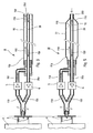
- the figure 1 illustrates, in schematic longitudinal section, a first embodiment according to the present invention.
- the figure 2 illustrates the implantation, in a patient, of the probe of the figure 1 when said probe is of the nasal type.
- FIGS 3 and 5 respectively illustrate, in schematic longitudinal section, two other embodiments according to the present invention.
- the figure 4 illustrates the implantation, in a patient, of the probe of the figure 3 when said probe is of the mouth type.
- the respiratory probe I according to the present invention and represented on the figure 1 has two independent airways, in parallel, respectively constituted by flexible tubes 1 and 2.
- said flexible tubes 1 and 2 are connected together at the outlet 3 of an artificial respirator 4 (very partially shown) via respective unidirectional valves 5 and 6.
- the valve 5, mounted on the flexible tube 1 is passing from the proximal end 1p to the distal end 1d of said flexible tube 1 and blocking in the opposite direction.
- the valve 6, mounted on the flexible tube 2 is passing from the distal end 2d to the proximal end 2p of said flexible tube 2 and blocking in the opposite direction.
- the probe I may be of the mouth type, it is particularly suitable for use as a nasal probe, as schematically illustrated on the figure 2 .
- the lungs P of a patient there is shown schematically the lungs P of a patient, the distal ends 1d and 2d of said tubes 1 and 2 being respectively introduced into the nostrils of said patient.
- the polluted respiratory gas corresponding to a previous pulse of gas and found in the lungs P, is driven out of these and is sent to the artificial respirator 4 through the tube 2 and the valve 6, as is illustrated by the arrows f2 on the figure 1 .
- the artificial respirator 4 detects the arrival of this polluted respiratory gas corresponding to an expiration of the patient and can send a new pulse of breathing gas, corresponding to an inspiration, to said lungs P.
- FIG 3 there is shown a probe II, according to the present invention, in which the two independent airways, respectively formed by flexible tubes 10 and 20, are coaxial, instead of being parallel as the channels 1 and 2 of the probe I.
- the arrangement 3, 4, 5 and 6 which is described next to the figure 1 and to which are connected the proximal ends 10p and 20p of said flexible tubes 10 and 20.
- Probe II could be nasal type; however, it is advantageously of the mouth type, as illustrated on the figure 4 . Indeed, in this case, it can be introduced into the patient's respiratory apparatus, until the distal ends 10d and 20d of the coaxial flexible tubes 10 and 20 are in the vicinity of the careen C. Thus, the Dead space between the distal end of the probe II and the lungs P is reduced to a minimum.
- the polluted respiratory gas found in the lungs P is driven out of these, from the careen C and through the central tube 20, as illustrated by the arrows f20 on the figure 3 .
- a new pulse of respiratory gas can then be sent by the artificial respirator 4 (arrows f10) to the lungs P.
- probe III there is shown an embodiment variant III of the probe II of the figure 3 .
- probe III there is the arrangement 3, 4, 5, 6 and 20 described above.
- the peripheral tube 10 is replaced by a flexible sheath 11 which surrounds the central tube 20 and whose proximal end 11p is connected to the valve 5.
- the distal end 11d of the flexible sheath 11 is integrally connected to the distal end 20d and said tube 20 has, in the vicinity of its distal end 20d, a through passage 12, located inside the flexible sheath 11.
- the respiratory gas pulses (arrows f10 ) generated by the artificial respirator 4
Landscapes
- Health & Medical Sciences (AREA)
- Pulmonology (AREA)
- Heart & Thoracic Surgery (AREA)
- Engineering & Computer Science (AREA)
- Anesthesiology (AREA)
- Biomedical Technology (AREA)
- Emergency Medicine (AREA)
- Hematology (AREA)
- Life Sciences & Earth Sciences (AREA)
- Animal Behavior & Ethology (AREA)
- General Health & Medical Sciences (AREA)
- Public Health (AREA)
- Veterinary Medicine (AREA)
- Measurement Of The Respiration, Hearing Ability, Form, And Blood Characteristics Of Living Organisms (AREA)
- Percussion Or Vibration Massage (AREA)
Abstract
Description
La présente invention concerne un ensemble respiratoire comportant un respirateur artificiel et une sonde respiratoire, sonde- dont l'extrémité distale est destinée à être introduite dans l'appareil respiratoire d'un patient et dont l'extrémité proximale est reliée à la sortie dudit respirateur artificiel engendrant des impulsions de gaz respiratoire, correspondant à des inspirations pour ledit patient, en réponse aux impulsions de gaz respiratoire pollué expirées par le patient.The present invention relates to a respiratory assembly comprising an artificial respirator and a respiratory probe, a probe whose distal end is intended to be introduced into the respiratory apparatus of a patient and whose proximal end is connected to the outlet of said ventilator. artificial generating respiratory gas pulses, corresponding to inspirations for said patient, in response to pulses of polluted respiratory gas exhaled by the patient.
Dans les ensembles respiratoires de ce type, le gaz respiratoire frais et le gaz respiratoire pollué (chargé de gaz carbonique) circulent en alternance dans la sonde, mais en sens opposés. Par ailleurs, il est courant que, lors des expirations, la totalité du gaz respiratoire pollué ne soit pas évacué. Il en résulte donc que ce gaz respiratoire pollué non évacué s'oppose à l'introduction consécutive du gaz respiratoire frais, ce qui a pour conséquence une mauvaise oxygénation du patient. Pour tenter d'éviter cet inconvénient, on augmente alors la pression sous laquelle ledit respirateur artificiel délivre le gaz respiratoire frais, pour aider à chasser le gaz respiratoire pollué. Mais alors, on risque de blesser le patient, surtout si celui-ci est un enfant.In respiratory sets of this type, the fresh respiratory gas and the polluted respiratory gas (charged with carbon dioxide) circulate alternately in the probe, but in opposite directions. Moreover, it is common that during exhalation, all the polluted respiratory gas is not evacuated. As a result, this non-evacuated polluted respiratory gas is opposed to the subsequent introduction of the fresh respiratory gas, which results in poor oxygenation of the patient. In an attempt to avoid this disadvantage, the pressure under which said artificial respirator delivers fresh respiratory gas is then increased to help flush the polluted respiratory gas. But then, we risk hurting the patient, especially if he is a child.
La présente invention a pour objet de remédier à ces inconvénients.The present invention aims to overcome these disadvantages.
A cette fin, selon l'invention, l'ensemble respiratoire comportant :
- un respirateur artificiel pourvu d'une sortie par laquelle ledit respirateur artificiel :
- . reçoit des impulsions de gaz respiratoire pollué correspondant à des expirations d'un patient, et
- . en réponse auxdites impulsions de gaz respiratoire pollué, émet des impulsions de gaz respiratoire frais correspondant à des inspirations dudit patient ; et
- une sonde respiratoire dont l'extrémité distale est destinée à être introduite dans l'appareil respiratoire dudit patient et dont l'extrémité proximale est reliée à ladite sortie dudit respirateur artificiel,
- ladite sonde comporte deux voies indépendantes dont :
- . les extrémités distales sont destinées à être introduites en commun dans ledit appareil respiratoire du patient, et
- . les extrémités proximales sont reliées en commun à ladite sortie dudit respirateur artificiel par l'intermédiaire de valves unidirectionnelles respectives ; et
- l'une desdites valves unidirectionnelles est passante de l'extrémité proximale vers l'extrémité distale de la voie à laquelle elle est reliée, tandis que l'autre desdites valves unidirectionnelles est passante de l'extrémité distale vers l'extrémité proximale de l'autre desdites voies à laquelle elle est reliée.
- an artificial respirator provided with an outlet by which said artificial respirator:
- . receives pulses of polluted respiratory gas corresponding to expirations of a patient, and
- . in response to said pulses of polluted respiratory gas, emits fresh respiratory gas pulses corresponding to inspirations of said patient; and
- a respiratory probe whose distal end is intended to be introduced into the respiratory apparatus of said patient and whose proximal end is connected to said outlet of said artificial respirator,
- said probe comprises two independent channels of which:
- . the distal ends are intended to be introduced in common into said patient's breathing apparatus, and
- . the proximal ends are connected in common to said outlet of said artificial respirator via respective unidirectional valves; and
- one of said unidirectional valves is passing from the proximal end to the distal end of the channel to which it is connected, while the other of said unidirectional valves is passing from the distal end to the proximal end of the other of said channels to which it is connected.
Ainsi, grâce à la présente invention, le gaz respiratoire pollué résiduel ne peut pas s'opposer à l'introduction du gaz respiratoire frais à travers la voie respiratoire pourvue de la valve unidirectionnelle passante de l'extrémité proximale vers l'extrémité distale. De plus, rien ne s'oppose à l'évacuation, à travers l'autre voie respiratoire, de l'éventuel gaz résiduel pollué sous l'action du gaz respiratoire frais introduit. Il n'y a donc aucune nécessité à injecter le gaz respiratoire sous une pression excessive.Thus, thanks to the present invention, the residual polluted respiratory gas can not oppose the introduction of the fresh respiratory gas through the respiratory tract provided with the unidirectional valve passing from the proximal end to the distal end. In addition, nothing prevents the evacuation, through the other airway, of any residual gas polluted by the action of fresh respiratory gas introduced. There is therefore no need to inject the respiratory gas under excessive pressure.
Lesdites voies de la sonde peuvent être disposées en parallèle ou bien coaxialement.Said channels of the probe may be arranged in parallel or coaxially.
Dans ce dernier cas, la sonde peut comporter une voie centrale constituée par un tube souple et une voie périphérique constituée par une gaine souple entourant ledit tube souple. Dans un mode de réalisation avantageux, l'extrémité distale de la gaine souple peut être solidarisée de l'extrémité distale dudit tube souple et-ce dernier peut comporter, au voisinage de son extrémité distale, au moins un passage traversant disposé à l'intérieur de ladite gaine souple.In the latter case, the probe may comprise a central channel formed by a flexible tube and a peripheral path constituted by a flexible sheath surrounding said flexible tube. In an advantageous embodiment, the distal end of the flexible sheath may be secured to the distal end of said flexible tube and the latter may comprise, in the vicinity of its distal end, at least one through passage arranged inside. of said flexible sheath.
La sonde peut être du type buccal ou nasal.The probe may be of the mouth or nasal type.
Les figures du dessin annexé feront bien comprendre comment l'invention peut être réalisée. Sur ces figures, des références identiques désignent des éléments semblables.The figures of the appended drawing will make it clear how the invention can be realized. In these figures, identical references designate similar elements.
La
La
Les
La
La sonde respiratoire I, conforme à la présente invention et représentée sur la
Du côté proximal, lesdits tubes souples 1 et 2 sont reliés en commun à la sortie 3 d'un respirateur artificiel 4 (très partiellement représenté) par l'intermédiaire de valves unidirectionnelles respectives 5 et 6. La valve 5, montée sur le tube souple 1, est passante de l'extrémité proximale 1p vers l'extrémité distale 1d dudit tube souple 1 et bloquante dans le sens inverse. Au contraire, la valve 6, montée sur le tube souple 2, est passante de l'extrémité distale 2d vers l'extrémité proximale 2p dudit tube souple 2 et bloquante dans le sens inverse.On the proximal side, said
Bien que la sonde I puisse être du type buccal, elle est particulièrement appropriée à être utilisée comme sonde nasale, comme cela est illustré schématiquement sur la
Ainsi, quand le respirateur artificiel 4 adresse à la sonde I une impulsion de gaz respiratoire correspondant à une inspiration pour ledit patient, cette impulsion est transmise auxdits poumons P, à travers la valve 5 et le tube 1, comme cela est illustré par les flèches f1 sur la
En revanche, le gaz respiratoire pollué, correspondant à une précédente impulsion de gaz et se trouvant dans les poumons P, est chassé hors de ceux-ci et est adressé au respirateur artificiel 4 à travers le tube 2 et la valve 6, comme cela est illustré par les flèches f2 sur la
On conçoit aisément que, grâce à ladite sonde I, l'introduction de gaz respiratoire dans les poumons P d'un patient ne peut être gênée par le gaz respiratoire pollué se trouvant dans lesdits poumons et que, au contraire, le gaz respiratoire pollué est éliminé hors de ceux-ci sans aucune difficulté.It is readily conceivable that, by said probe I, the introduction of respiratory gas into the lungs P of a patient can not be hindered by the polluted respiratory gas in said lungs and that, on the contrary, the polluted respiratory gas is eliminated out of these without any difficulty.
Sur la
La sonde II pourrait être de type nasal ; toutefois elle est avantageusement de type buccal, comme cela est illustré sur la
Ainsi, quand le respirateur artificiel 4 adresse à la sonde II une impulsion de gaz respiratoire correspondant à une inspiration pour le patient, cette impulsion est transmise à la carène C, à travers la valve 5 et le tube périphérique 10, comme cela est illustré par les flèches f10 sur la
En revanche, le gaz respiratoire pollué se trouvant dans les poumons P est chassé hors de ceux-ci, à partir de la carène C et à travers le tube central 20, comme cela est illustré par les flèches f20 sur la
Sur la
Claims (8)
caractérisé en ce que lesdites deux voies (1, 2) de la sonde sont disposées en parallèle.Assembly according to claim 1,
characterized in that said two channels (1, 2) of the probe are arranged in parallel.
caractérisé en ce que lesdites deux voies (10, 20 - 11, 20) de la sonde sont coaxiales.Assembly according to claim 1,
characterized in that said two channels (10, 20 - 11, 20) of the probe are coaxial.
caractérisé en ce que ladite sonde comporte :
characterized in that said probe comprises:
caractérisé en ce que l'extrémité distale (11d) de ladite gaine souple (11) est solidarisée de l'extrémité distale (20d) dudit tube souple central (20) et en ce que ledit tube souple (20) comporte au voisinage de son extrémité distale au moins un passage traversant (12) disposé à l'intérieur de ladite gaine souple (11).Assembly according to claim 4,
characterized in that the distal end (11d) of said flexible sheath (11) is secured to the distal end (20d) of said central flexible tube (20) and in that said flexible tube (20) has in the vicinity of its distal end at least one through passage (12) disposed within said flexible sheath (11).
caractérisé en ce que ladite sonde est de type buccal.Assembly according to one of Claims 1 to 5,
characterized in that said probe is of the mouth type.
caractérisé en ce que ladite sonde est de type nasal.Assembly according to one of Claims 1 to 5,
characterized in that said probe is of the nasal type.
Applications Claiming Priority (1)
| Application Number | Priority Date | Filing Date | Title |
|---|---|---|---|
| FR0702384A FR2914192B1 (en) | 2007-04-02 | 2007-04-02 | RESPIRATORY PROBE. |
Publications (2)
| Publication Number | Publication Date |
|---|---|
| EP1977780A1 true EP1977780A1 (en) | 2008-10-08 |
| EP1977780B1 EP1977780B1 (en) | 2017-10-04 |
Family
ID=38626388
Family Applications (1)
| Application Number | Title | Priority Date | Filing Date |
|---|---|---|---|
| EP08290230.5A Active EP1977780B1 (en) | 2007-04-02 | 2008-03-11 | Breathing apparatus with artificial respirator and probe |
Country Status (7)
| Country | Link |
|---|---|
| US (1) | US8678004B2 (en) |
| EP (1) | EP1977780B1 (en) |
| JP (2) | JP2008253754A (en) |
| KR (1) | KR101492869B1 (en) |
| CA (1) | CA2626725C (en) |
| ES (1) | ES2653464T3 (en) |
| FR (1) | FR2914192B1 (en) |
Cited By (3)
| Publication number | Priority date | Publication date | Assignee | Title |
|---|---|---|---|---|
| FR2936955A1 (en) * | 2008-10-15 | 2010-04-16 | Georges Boussignac | Artificial respiration device for resuscitation of patient in cardiac arrest state, has auxiliary tubular connector including isolating unit e.g. individual obturator, that isolates proximal ends of longitudinal channels from open air |
| EP2228088A1 (en) * | 2009-03-11 | 2010-09-15 | Georges Boussignac | Breathing device for assisted ventilation |
| CN102019015A (en) * | 2009-09-14 | 2011-04-20 | 乔治斯·鲍辛纳克 | Breathing device for assisted ventilation |
Families Citing this family (4)
| Publication number | Priority date | Publication date | Assignee | Title |
|---|---|---|---|---|
| GB2489275A (en) * | 2011-03-24 | 2012-09-26 | Christopher Alec Grace | Breathing device |
| US20140350648A1 (en) * | 2011-12-16 | 2014-11-27 | Dynasil Biomedical Corporation | Body temperature reduction systems and associated methods |
| WO2017159183A1 (en) * | 2016-03-16 | 2017-09-21 | オリンパス株式会社 | Medical piping member |
| KR101897152B1 (en) * | 2017-05-19 | 2018-09-11 | 배수진 | Nebulizer |
Citations (7)
| Publication number | Priority date | Publication date | Assignee | Title |
|---|---|---|---|---|
| US3815606A (en) * | 1972-09-21 | 1974-06-11 | C Mazal | Endotracheal catheter |
| US4265235A (en) * | 1979-05-11 | 1981-05-05 | Fukunaga Atsuo F | Anesthetic system |
| EP0747077A2 (en) * | 1995-06-07 | 1996-12-11 | Robert Maurice Raw | Endotracheal tube |
| US6155252A (en) * | 1995-03-17 | 2000-12-05 | Board Of Regents, The University Of Texas System | Method and apparatus for directing air flow within an intubated patient |
| WO2001024861A1 (en) * | 1999-10-01 | 2001-04-12 | Instrumentarium Ab | Ventilator tube |
| WO2002094360A1 (en) * | 2001-05-19 | 2002-11-28 | Intersurgical Ltd | Inhalation handset |
| WO2006090043A1 (en) * | 2005-02-23 | 2006-08-31 | Georges Boussignac | Respiratory tube |
Family Cites Families (14)
| Publication number | Priority date | Publication date | Assignee | Title |
|---|---|---|---|---|
| US2766753A (en) * | 1954-04-15 | 1956-10-16 | Dragerwerk Fa | Apparatus for artificial respiration, in particular for purposes of anesthesia |
| DE1491691B1 (en) * | 1966-07-22 | 1969-12-04 | Draegerwerk Ag | Ventilator, especially for anesthesia ventilation |
| US4300550A (en) * | 1978-04-26 | 1981-11-17 | Becton, Dickinson And Company | Suction and oxygenation catheter |
| US4676239A (en) * | 1980-09-20 | 1987-06-30 | David Humphrey | Anesthetic system |
| DE3435849A1 (en) * | 1984-09-29 | 1986-04-30 | Paul Peter Prof. Dr.med. 4400 Münster Lunkenheimer | AIR PULSE GENERATOR IN VENTILATORS |
| US5335656A (en) * | 1988-04-15 | 1994-08-09 | Salter Laboratories | Method and apparatus for inhalation of treating gas and sampling of exhaled gas for quantitative analysis |
| US5605149A (en) * | 1995-03-17 | 1997-02-25 | Board Of Regents, The University Of Texas System | Method and apparatus for directing air flow within an intubated patient |
| SE504257C2 (en) * | 1995-12-01 | 1996-12-16 | Siemens Elema Ab | Method for pressure measurement in fan systems by means of two separate gas lines and one fan system |
| JP2000042110A (en) | 1998-07-30 | 2000-02-15 | Senko Medical Instr Mfg Co Ltd | Vent line for respiratory device |
| US6398754B1 (en) * | 1998-09-30 | 2002-06-04 | Allergan, Inc. | Phaco tip with fluid bypass port |
| BR0102116B1 (en) * | 2000-05-10 | 2010-09-21 | component for a breathing circuit member. | |
| US6626175B2 (en) * | 2000-10-06 | 2003-09-30 | Respironics, Inc. | Medical ventilator triggering and cycling method and mechanism |
| DE10123278C1 (en) * | 2001-05-10 | 2002-06-13 | Univ Hamburg | Breathing device used in intensive care or during anesthesia comprises a respirator, an outlet, an inhalation tube, a twin-channel endotracheal tube, flow meters, pressure meters, and an evaluation device |
| ATE328629T1 (en) * | 2001-09-24 | 2006-06-15 | Atsuo F Fukunaga | BREATHING CIRCUIT WITH UNCONVENTIONAL BREATHING LINES AND SYSTEMS AND METHODS FOR OPTIMIZING THE USE OF FRESH GASES |
-
2007
- 2007-04-02 FR FR0702384A patent/FR2914192B1/en not_active Expired - Fee Related
- 2007-06-18 US US11/764,437 patent/US8678004B2/en active Active
-
2008
- 2008-03-11 EP EP08290230.5A patent/EP1977780B1/en active Active
- 2008-03-11 ES ES08290230.5T patent/ES2653464T3/en active Active
- 2008-03-18 JP JP2008068640A patent/JP2008253754A/en active Pending
- 2008-03-20 CA CA2626725A patent/CA2626725C/en active Active
- 2008-03-28 KR KR20080029335A patent/KR101492869B1/en active IP Right Grant
-
2013
- 2013-06-04 JP JP2013117856A patent/JP5613796B2/en active Active
Patent Citations (7)
| Publication number | Priority date | Publication date | Assignee | Title |
|---|---|---|---|---|
| US3815606A (en) * | 1972-09-21 | 1974-06-11 | C Mazal | Endotracheal catheter |
| US4265235A (en) * | 1979-05-11 | 1981-05-05 | Fukunaga Atsuo F | Anesthetic system |
| US6155252A (en) * | 1995-03-17 | 2000-12-05 | Board Of Regents, The University Of Texas System | Method and apparatus for directing air flow within an intubated patient |
| EP0747077A2 (en) * | 1995-06-07 | 1996-12-11 | Robert Maurice Raw | Endotracheal tube |
| WO2001024861A1 (en) * | 1999-10-01 | 2001-04-12 | Instrumentarium Ab | Ventilator tube |
| WO2002094360A1 (en) * | 2001-05-19 | 2002-11-28 | Intersurgical Ltd | Inhalation handset |
| WO2006090043A1 (en) * | 2005-02-23 | 2006-08-31 | Georges Boussignac | Respiratory tube |
Cited By (5)
| Publication number | Priority date | Publication date | Assignee | Title |
|---|---|---|---|---|
| FR2936955A1 (en) * | 2008-10-15 | 2010-04-16 | Georges Boussignac | Artificial respiration device for resuscitation of patient in cardiac arrest state, has auxiliary tubular connector including isolating unit e.g. individual obturator, that isolates proximal ends of longitudinal channels from open air |
| EP2228088A1 (en) * | 2009-03-11 | 2010-09-15 | Georges Boussignac | Breathing device for assisted ventilation |
| FR2942966A1 (en) * | 2009-03-11 | 2010-09-17 | Georges Boussignac | RESPIRATORY ASSISTANCE DEVICE |
| CN102019015A (en) * | 2009-09-14 | 2011-04-20 | 乔治斯·鲍辛纳克 | Breathing device for assisted ventilation |
| CN102019015B (en) * | 2009-09-14 | 2015-01-28 | 乔治斯·鲍辛纳克 | Breathing device for assisted ventilation |
Also Published As
| Publication number | Publication date |
|---|---|
| JP2013166049A (en) | 2013-08-29 |
| ES2653464T3 (en) | 2018-02-07 |
| KR101492869B1 (en) | 2015-02-16 |
| FR2914192B1 (en) | 2010-03-26 |
| CA2626725A1 (en) | 2008-10-02 |
| US20080236591A1 (en) | 2008-10-02 |
| EP1977780B1 (en) | 2017-10-04 |
| CA2626725C (en) | 2015-06-16 |
| JP5613796B2 (en) | 2014-10-29 |
| JP2008253754A (en) | 2008-10-23 |
| KR20080090290A (en) | 2008-10-08 |
| FR2914192A1 (en) | 2008-10-03 |
| US8678004B2 (en) | 2014-03-25 |
Similar Documents
| Publication | Publication Date | Title |
|---|---|---|
| EP1977780B1 (en) | Breathing apparatus with artificial respirator and probe | |
| CA2418447C (en) | Respiratory aid device | |
| CA2030546C (en) | Apparatus for assisted ventilation | |
| EP0245142B1 (en) | Tube for respiratory assistance | |
| CA2695570C (en) | Breathing assistance device | |
| EP0701834A1 (en) | Respiratory assistance device | |
| FR2782012A1 (en) | DEVICE FOR BREATHING ASSISTANCE | |
| EP0983772B1 (en) | Respiratory assistance device | |
| EP2001540A1 (en) | Artificial respiration device for patients suffering from hypoxemia or anoxemia | |
| FR2912660A1 (en) | Artificial respiration device for intensive care of patient, has controlling unit controlling entry of exterior air in tubular element at beginning of each decompression imposed to thoracic cage of person | |
| FR2973708A1 (en) | RESPIRATORY ASSISTANCE DEVICE | |
| EP2195060A2 (en) | Respiratory assistance device | |
| EP2239004A1 (en) | Respiratory aid device and measurement system comprising such a device | |
| EP2670467B1 (en) | Artificial respiration device for resuscitating a person in a state of cardiac arrest | |
| FR3022146A1 (en) | RESPIRATORY ASSISTANCE DEVICE, NASAL APPARATUS AND RESPIRATORY ASSISTANCE MASK | |
| FR2911073A1 (en) | Artificial respiration device for patient suffering from e.g. cardiac arrest, has pressure drop element assuring that utilization pressure of gas is equal to higher value of utilization value range when supply pressure has maximum value | |
| EP2417995B1 (en) | Respiratory assistance system | |
| FR2991571A1 (en) | Inhalation mask for providing drug inhalation therapy to horses to treat inflammatory diseases of air routes in nose of equines, has connecting portion formed with body for defining passage for gas flow from inhalation device to nostril | |
| EP4085958B1 (en) | Ventilation device with continuous pressure adapted to the treatment of patients with respiratory failure | |
| FR2597754A1 (en) | Tube for respiratory assistance | |
| FR2980978A1 (en) | Artificial respiration device for resuscitation of person suffering from cardiac arrest, has upstream auxiliary channel connected with respiratory gas source to infuse upstream jet of respiratory gas in main channel | |
| FR2940128A1 (en) | Artificial respiration device for ventilation of patient, has protection unit propelled in passage direction of proximal end of body during compressions of thoracic cage, where unit is mounted at proximal end | |
| FR2608054A2 (en) | Improved tube for respiratory assistance |
Legal Events
| Date | Code | Title | Description |
|---|---|---|---|
| PUAI | Public reference made under article 153(3) epc to a published international application that has entered the european phase |
Free format text: ORIGINAL CODE: 0009012 |
|
| AK | Designated contracting states |
Kind code of ref document: A1 Designated state(s): AT BE BG CH CY CZ DE DK EE ES FI FR GB GR HR HU IE IS IT LI LT LU LV MC MT NL NO PL PT RO SE SI SK TR |
|
| AX | Request for extension of the european patent |
Extension state: AL BA MK RS |
|
| 17P | Request for examination filed |
Effective date: 20081027 |
|
| 17Q | First examination report despatched |
Effective date: 20081201 |
|
| AKX | Designation fees paid |
Designated state(s): AT BE BG CH CY CZ DE DK EE ES FI FR GB GR HR HU IE IS IT LI LT LU LV MC MT NL NO PL PT RO SE SI SK TR |
|
| 111L | Licence recorded |
Designated state(s): AT BE BG CH CY CZ DE DK EE ES FI FR GB GR HR HU IE IS IT LT LU LV MC MT NL NO PL PT RO SE SI SK TR Free format text: EXCLUSIVE LICENSE Name of requester: VYGON, FR Effective date: 20160404 |
|
| GRAP | Despatch of communication of intention to grant a patent |
Free format text: ORIGINAL CODE: EPIDOSNIGR1 |
|
| INTG | Intention to grant announced |
Effective date: 20170511 |
|
| GRAA | (expected) grant |
Free format text: ORIGINAL CODE: 0009210 |
|
| GRAS | Grant fee paid |
Free format text: ORIGINAL CODE: EPIDOSNIGR3 |
|
| 111L | Licence recorded |
Designated state(s): AT BE BG CH CY CZ DE DK EE ES FI FR GB GR HR HU IE IS IT LT LU LV MC MT NL NO PL PT RO SE SI SK TR Free format text: EXCLUSIVE LICENSE Name of requester: VYGON, FR Effective date: 20160404 |
|
| AK | Designated contracting states |
Kind code of ref document: B1 Designated state(s): AT BE BG CH CY CZ DE DK EE ES FI FR GB GR HR HU IE IS IT LI LT LU LV MC MT NL NO PL PT RO SE SI SK TR |
|
| REG | Reference to a national code |
Ref country code: GB Ref legal event code: FG4D Free format text: NOT ENGLISH |
|
| REG | Reference to a national code |
Ref country code: CH Ref legal event code: EP Ref country code: CH Ref legal event code: PK Free format text: COMPLEMENT D'ENREGISTREMENT DE LICENCE: LICENCE EXCLUSIVE |
|
| REG | Reference to a national code |
Ref country code: AT Ref legal event code: REF Ref document number: 933427 Country of ref document: AT Kind code of ref document: T Effective date: 20171015 |
|
| REG | Reference to a national code |
Ref country code: IE Ref legal event code: FG4D Free format text: LANGUAGE OF EP DOCUMENT: FRENCH |
|
| REG | Reference to a national code |
Ref country code: DE Ref legal event code: R096 Ref document number: 602008052345 Country of ref document: DE |
|
| REG | Reference to a national code |
Ref country code: FR Ref legal event code: PLFP Year of fee payment: 11 |
|
| REG | Reference to a national code |
Ref country code: ES Ref legal event code: FG2A Ref document number: 2653464 Country of ref document: ES Kind code of ref document: T3 Effective date: 20180207 Ref country code: NL Ref legal event code: MP Effective date: 20171004 |
|
| REG | Reference to a national code |
Ref country code: LT Ref legal event code: MG4D |
|
| REG | Reference to a national code |
Ref country code: AT Ref legal event code: MK05 Ref document number: 933427 Country of ref document: AT Kind code of ref document: T Effective date: 20171004 |
|
| PG25 | Lapsed in a contracting state [announced via postgrant information from national office to epo] |
Ref country code: NL Free format text: LAPSE BECAUSE OF FAILURE TO SUBMIT A TRANSLATION OF THE DESCRIPTION OR TO PAY THE FEE WITHIN THE PRESCRIBED TIME-LIMIT Effective date: 20171004 |
|
| PG25 | Lapsed in a contracting state [announced via postgrant information from national office to epo] |
Ref country code: NO Free format text: LAPSE BECAUSE OF FAILURE TO SUBMIT A TRANSLATION OF THE DESCRIPTION OR TO PAY THE FEE WITHIN THE PRESCRIBED TIME-LIMIT Effective date: 20180104 Ref country code: LT Free format text: LAPSE BECAUSE OF FAILURE TO SUBMIT A TRANSLATION OF THE DESCRIPTION OR TO PAY THE FEE WITHIN THE PRESCRIBED TIME-LIMIT Effective date: 20171004 Ref country code: FI Free format text: LAPSE BECAUSE OF FAILURE TO SUBMIT A TRANSLATION OF THE DESCRIPTION OR TO PAY THE FEE WITHIN THE PRESCRIBED TIME-LIMIT Effective date: 20171004 Ref country code: SE Free format text: LAPSE BECAUSE OF FAILURE TO SUBMIT A TRANSLATION OF THE DESCRIPTION OR TO PAY THE FEE WITHIN THE PRESCRIBED TIME-LIMIT Effective date: 20171004 |
|
| PG25 | Lapsed in a contracting state [announced via postgrant information from national office to epo] |
Ref country code: LV Free format text: LAPSE BECAUSE OF FAILURE TO SUBMIT A TRANSLATION OF THE DESCRIPTION OR TO PAY THE FEE WITHIN THE PRESCRIBED TIME-LIMIT Effective date: 20171004 Ref country code: IS Free format text: LAPSE BECAUSE OF FAILURE TO SUBMIT A TRANSLATION OF THE DESCRIPTION OR TO PAY THE FEE WITHIN THE PRESCRIBED TIME-LIMIT Effective date: 20180204 Ref country code: BG Free format text: LAPSE BECAUSE OF FAILURE TO SUBMIT A TRANSLATION OF THE DESCRIPTION OR TO PAY THE FEE WITHIN THE PRESCRIBED TIME-LIMIT Effective date: 20180104 Ref country code: HR Free format text: LAPSE BECAUSE OF FAILURE TO SUBMIT A TRANSLATION OF THE DESCRIPTION OR TO PAY THE FEE WITHIN THE PRESCRIBED TIME-LIMIT Effective date: 20171004 Ref country code: AT Free format text: LAPSE BECAUSE OF FAILURE TO SUBMIT A TRANSLATION OF THE DESCRIPTION OR TO PAY THE FEE WITHIN THE PRESCRIBED TIME-LIMIT Effective date: 20171004 Ref country code: GR Free format text: LAPSE BECAUSE OF FAILURE TO SUBMIT A TRANSLATION OF THE DESCRIPTION OR TO PAY THE FEE WITHIN THE PRESCRIBED TIME-LIMIT Effective date: 20180105 |
|
| REG | Reference to a national code |
Ref country code: DE Ref legal event code: R097 Ref document number: 602008052345 Country of ref document: DE |
|
| PG25 | Lapsed in a contracting state [announced via postgrant information from national office to epo] |
Ref country code: DK Free format text: LAPSE BECAUSE OF FAILURE TO SUBMIT A TRANSLATION OF THE DESCRIPTION OR TO PAY THE FEE WITHIN THE PRESCRIBED TIME-LIMIT Effective date: 20171004 Ref country code: SK Free format text: LAPSE BECAUSE OF FAILURE TO SUBMIT A TRANSLATION OF THE DESCRIPTION OR TO PAY THE FEE WITHIN THE PRESCRIBED TIME-LIMIT Effective date: 20171004 Ref country code: EE Free format text: LAPSE BECAUSE OF FAILURE TO SUBMIT A TRANSLATION OF THE DESCRIPTION OR TO PAY THE FEE WITHIN THE PRESCRIBED TIME-LIMIT Effective date: 20171004 Ref country code: CZ Free format text: LAPSE BECAUSE OF FAILURE TO SUBMIT A TRANSLATION OF THE DESCRIPTION OR TO PAY THE FEE WITHIN THE PRESCRIBED TIME-LIMIT Effective date: 20171004 |
|
| PLBE | No opposition filed within time limit |
Free format text: ORIGINAL CODE: 0009261 |
|
| STAA | Information on the status of an ep patent application or granted ep patent |
Free format text: STATUS: NO OPPOSITION FILED WITHIN TIME LIMIT |
|
| PG25 | Lapsed in a contracting state [announced via postgrant information from national office to epo] |
Ref country code: PL Free format text: LAPSE BECAUSE OF FAILURE TO SUBMIT A TRANSLATION OF THE DESCRIPTION OR TO PAY THE FEE WITHIN THE PRESCRIBED TIME-LIMIT Effective date: 20171004 Ref country code: RO Free format text: LAPSE BECAUSE OF FAILURE TO SUBMIT A TRANSLATION OF THE DESCRIPTION OR TO PAY THE FEE WITHIN THE PRESCRIBED TIME-LIMIT Effective date: 20171004 |
|
| 26N | No opposition filed |
Effective date: 20180705 |
|
| PG25 | Lapsed in a contracting state [announced via postgrant information from national office to epo] |
Ref country code: MT Free format text: LAPSE BECAUSE OF FAILURE TO SUBMIT A TRANSLATION OF THE DESCRIPTION OR TO PAY THE FEE WITHIN THE PRESCRIBED TIME-LIMIT Effective date: 20171004 |
|
| REG | Reference to a national code |
Ref country code: CH Ref legal event code: PL |
|
| PG25 | Lapsed in a contracting state [announced via postgrant information from national office to epo] |
Ref country code: MC Free format text: LAPSE BECAUSE OF FAILURE TO SUBMIT A TRANSLATION OF THE DESCRIPTION OR TO PAY THE FEE WITHIN THE PRESCRIBED TIME-LIMIT Effective date: 20171004 Ref country code: SI Free format text: LAPSE BECAUSE OF FAILURE TO SUBMIT A TRANSLATION OF THE DESCRIPTION OR TO PAY THE FEE WITHIN THE PRESCRIBED TIME-LIMIT Effective date: 20171004 |
|
| REG | Reference to a national code |
Ref country code: BE Ref legal event code: MM Effective date: 20180331 |
|
| REG | Reference to a national code |
Ref country code: IE Ref legal event code: MM4A |
|
| PG25 | Lapsed in a contracting state [announced via postgrant information from national office to epo] |
Ref country code: LU Free format text: LAPSE BECAUSE OF NON-PAYMENT OF DUE FEES Effective date: 20180311 |
|
| PG25 | Lapsed in a contracting state [announced via postgrant information from national office to epo] |
Ref country code: IE Free format text: LAPSE BECAUSE OF NON-PAYMENT OF DUE FEES Effective date: 20180311 |
|
| PG25 | Lapsed in a contracting state [announced via postgrant information from national office to epo] |
Ref country code: LI Free format text: LAPSE BECAUSE OF NON-PAYMENT OF DUE FEES Effective date: 20180331 Ref country code: CH Free format text: LAPSE BECAUSE OF NON-PAYMENT OF DUE FEES Effective date: 20180331 Ref country code: BE Free format text: LAPSE BECAUSE OF NON-PAYMENT OF DUE FEES Effective date: 20180331 |
|
| PG25 | Lapsed in a contracting state [announced via postgrant information from national office to epo] |
Ref country code: TR Free format text: LAPSE BECAUSE OF FAILURE TO SUBMIT A TRANSLATION OF THE DESCRIPTION OR TO PAY THE FEE WITHIN THE PRESCRIBED TIME-LIMIT Effective date: 20171004 |
|
| PG25 | Lapsed in a contracting state [announced via postgrant information from national office to epo] |
Ref country code: PT Free format text: LAPSE BECAUSE OF FAILURE TO SUBMIT A TRANSLATION OF THE DESCRIPTION OR TO PAY THE FEE WITHIN THE PRESCRIBED TIME-LIMIT Effective date: 20171004 Ref country code: HU Free format text: LAPSE BECAUSE OF FAILURE TO SUBMIT A TRANSLATION OF THE DESCRIPTION OR TO PAY THE FEE WITHIN THE PRESCRIBED TIME-LIMIT; INVALID AB INITIO Effective date: 20080311 |
|
| PG25 | Lapsed in a contracting state [announced via postgrant information from national office to epo] |
Ref country code: CY Free format text: LAPSE BECAUSE OF FAILURE TO SUBMIT A TRANSLATION OF THE DESCRIPTION OR TO PAY THE FEE WITHIN THE PRESCRIBED TIME-LIMIT Effective date: 20171004 |
|
| PGFP | Annual fee paid to national office [announced via postgrant information from national office to epo] |
Ref country code: IT Payment date: 20230203 Year of fee payment: 16 Ref country code: GB Payment date: 20230110 Year of fee payment: 16 Ref country code: DE Payment date: 20230111 Year of fee payment: 16 |
|
| P01 | Opt-out of the competence of the unified patent court (upc) registered |
Effective date: 20230524 |
|
| PGFP | Annual fee paid to national office [announced via postgrant information from national office to epo] |
Ref country code: ES Payment date: 20230406 Year of fee payment: 16 |
|
| PGFP | Annual fee paid to national office [announced via postgrant information from national office to epo] |
Ref country code: FR Payment date: 20231219 Year of fee payment: 17 |