EP1988465A1 - Multiprocessor system, processor, and cache control method - Google Patents
Multiprocessor system, processor, and cache control method Download PDFInfo
- Publication number
- EP1988465A1 EP1988465A1 EP06714578A EP06714578A EP1988465A1 EP 1988465 A1 EP1988465 A1 EP 1988465A1 EP 06714578 A EP06714578 A EP 06714578A EP 06714578 A EP06714578 A EP 06714578A EP 1988465 A1 EP1988465 A1 EP 1988465A1
- Authority
- EP
- European Patent Office
- Prior art keywords
- data
- unit
- cache
- request
- read
- Prior art date
- Legal status (The legal status is an assumption and is not a legal conclusion. Google has not performed a legal analysis and makes no representation as to the accuracy of the status listed.)
- Granted
Links
Images


Classifications
-
- G—PHYSICS
- G06—COMPUTING; CALCULATING OR COUNTING
- G06F—ELECTRIC DIGITAL DATA PROCESSING
- G06F12/00—Accessing, addressing or allocating within memory systems or architectures
- G06F12/02—Addressing or allocation; Relocation
- G06F12/08—Addressing or allocation; Relocation in hierarchically structured memory systems, e.g. virtual memory systems
- G06F12/0802—Addressing of a memory level in which the access to the desired data or data block requires associative addressing means, e.g. caches
- G06F12/0806—Multiuser, multiprocessor or multiprocessing cache systems
- G06F12/0811—Multiuser, multiprocessor or multiprocessing cache systems with multilevel cache hierarchies
-
- G—PHYSICS
- G06—COMPUTING; CALCULATING OR COUNTING
- G06F—ELECTRIC DIGITAL DATA PROCESSING
- G06F2212/00—Indexing scheme relating to accessing, addressing or allocation within memory systems or architectures
- G06F2212/10—Providing a specific technical effect
- G06F2212/1032—Reliability improvement, data loss prevention, degraded operation etc
Definitions
- the present invention relates to a multiprocessor system having a plurality of processors each including a primary cache and a secondary cache shared by the processors, and a cache control method, and, more particularly to a multiprocessor system, a processor, and a cache control method that can prevent competitions for data acquisition by a plurality of caches, and reduce delay in data transfer between caches.
- frequently used data is stored in a cache memory separate from a main memory, to improve processing speed. While the cache memory has a smaller capacity than that of the main memory, high-speed access is possible. Therefore, by storing the frequently used data in the cache memory, while replacing the data at any time, greater processing speed can be achieved.
- the cache memory is provided hierarchically, and at the time of performing the processing, the primary cache having the highest speed (hereinafter, "L1 cache”) is first accessed, and if there is no desired data in the L1 cache, then the secondary cache (hereinafter, "L2 cache”) having the next highest speed is accessed.
- L1 cache the primary cache having the highest speed
- L2 cache the secondary cache having the next highest speed
- a plurality of processors can be mounted on one information processor.
- an on-chip multiprocessor system in which a plurality of processors are mounted on one chip has been realized.
- the L2 cache shared by respective processors can be provided, separately from the L1 cache in each processor (for example, see Patent Document 1).
- Patent Document 1 Japanese Patent Application Laid-open No. 2002-373115
- a cache miss occurs simultaneously relating to the same data in the L1 cache in each processor, a plurality of processors can access the shared L2 cache simultaneously to cause competitions for data acquisition.
- MI move in
- a move out (hereinafter, abbreviated as "MO") command for moving the data A out from the L1 cache #1 is issued.
- the L1 cache #1 a store process of the data A has not been completed; however, according to the MO command from the L2 cache controller, as shown in Fig. 4-3 , an MO request for requesting MO of the data A is made, and the data A is transferred to the L2 cache controller. Simultaneously, the L2 cache controller transfers the data A to the L1 cache #2.
- the store process of the data A has not been completed; however, according to the MO command from the L2 cache controller, as shown in Fig. 4-5 , an MO request for requesting MO of the data A is made, and the data A is transferred to the L2 cache controller. Simultaneously, the L2 cache controller transfers the data A to the L1 cache #1.
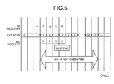
- a method in which after the MI request is once made and the data is transferred to the L1 cache, MO is prohibited in the L1 cache for a while can be considered. That is, for example, as shown in Fig. 5 , the MI request obtains priority of a pipeline process, and after a process of predetermined P cycle is complete, a counter starts counting up of the predetermined cycle (in Fig. 5 , 31 cycles). Thereafter, a process of a predetermined T cycle, a process of a predetermined M cycle, a process of a predetermined B cycle, and a process of a predetermined R cycle are performed with respect to the MI request, and data is stored in the L1 cache.
- the present invention has been achieved to solve the above problem, and it is an object of the present invention to provide a multiprocessor system, a processor, and a cache control method that can prevent competitions for data acquisition by a plurality of caches, and reduce delay in data transfer between caches.
- a multiprocessor system has a plurality of processors each including a primary cache, and a secondary cache shared by the processors, and the processors each include a read unit that reads data from the primary cache in the processor itself, a request unit that requests an external device to write the data in the primary cache, when the data to be read is not stored in the primary cache, a measuring unit that measures an elapsed time since a write request is made by the request unit, a receiving unit that receives a read command instructing to read data in the primary cache from an external device, a comparing unit that compares specific information for specifying the data, for which the read command has been received by the receiving unit, with specific information for specifying the data, for which the write request has been made by the request unit, and a controller that suspends reading of the data by the read unit according to the read command, when pieces of specific information are the same, as a result of comparison by the comparing unit, and an elapsed time measured by the measuring unit is
- the controller includes a generating unit that generates a read request for requesting the read unit to read the data according to the read command, when the pieces of specific information are not the same as a result of comparison by the comparing unit.
- the generating unit generates the read request of the data according to the read command, even when the pieces of specific information are the same as a result of comparison by the comparing unit, if the elapsed time measured by the measuring unit is equal to or longer than a predetermined time.
- the controller when the elapsed time measured by the measuring unit reaches the predetermined time, the controller allows the read unit to read the data, whose readout has been suspended.
- the comparing unit compares an address of data in a main memory as the specific information.
- the comparing unit compares a part of an address and a way in the primary cache corresponding to the data as the specific information.
- the measuring unit measures the elapsed time since the data is written in response to the write request by the write unit.
- a processor has a cache for storing data, and includes a write unit that writes data in the cache, a measuring unit that measures an elapsed time since data is written in the cache by the write unit, a receiving unit that receives a read command instructing to read data in the cache from an external device, a comparing unit that compares specific information for specifying the data, for which the read command has been received by the receiving unit, with specific information for specifying the data written by the write unit, and a read controller that suspends reading of the data according to the read command, when the pieces of specific information are the same as a result of comparison by the comparing unit, and an elapsed time measured by the measuring unit is less than a predetermined time.
- a cache control method in a multiprocessor system having a plurality of processors each including a primary cache, and a secondary cache shared by the processors, includes requesting an external device to write data in the primary cache, when the data to be read is not stored in the primary cache, starting measuring an elapsed time after a write request is made in the requesting, receiving a read command instructing to read data in the primary cache from an external device, comparing specific information for specifying the data, for which the read command has been received in the receiving, with specific information for specifying the data, for which the write request has been made in the requesting, and controlling to suspend reading of the data according to the read command, when pieces of specific information are the same, as a result of comparison in the comparing, and the elapsed time measured in the measuring is less than a predetermined time.
- the present invention when data to be read is not stored in the primary cache, writing of the data into the primary cache is requested to an external device, an elapsed time since the write request is measured, a read command indicating data read from the primary cache is received from the external device, specific information for specifying data, for which the read command has been received, is compared with specific information for specifying data, for which the write request has been made, and as a result of comparison, when the pieces of specific information are the same and when the measured elapsed time is less than a predetermined period of time, data read corresponding to the read command is suspended.
- the data just written in the primary cache is prevented from being read, and a time for the processing with respect to the data can be ensured, to thereby prevent competitions for acquiring the data by a plurality of caches. Further, data other than the just written data can be read normally, whereby delay in data transfer between caches can be reduced.
- a read request for requesting data read according to the read command is generated. Accordingly, the data not matching the just written data can be read from the primary cache, immediately after the reception of the read command.
- the present invention as a result of comparison, even when the pieces of specific information are the same, if the measured elapsed time is equal to or longer than the predetermined period of time, a read request for requesting data read is generated according to the read command. Therefore, if the time required for the processing has been elapsed since data writing, even data written immediately before can be read from the primary cache, immediately after the reception of the read command, whereby the delay in the data transfer can be reduced further.
- the present invention when the measured elapsed time has reached the predetermined period of time, reading of data which has been suspended is performed. Therefore, delay in the data transfer can be reduced to the minimum also for the data, for which reading from the primary cache has been once suspended.
- an address of data in the main memory is compared as the specific information, matching or non-matching of data can be reliably determined.
- the present invention because a part of the address corresponding to the data and a way in the primary cache are compared as the specific information, matching or non-matching of data can be reliably determined, even when the cache is configured by a set associative method.
- the present invention because an elapsed time is measured since data is written in response to the write request, the time required for the processing since the data is written reliably in the primary cache can be ensured.
- data is written in the cache, an elapsed time since the data is written in the cache is measured, a read command indicating read of data in the cache is received from an external device, specific information for specifying data, for which the read command has been received, is compared with specific information for specifying written data, and as a result of comparison, if the pieces of specific information are the same and when the measured elapsed time is less than a predetermined period of time, data read according to the read command is suspended. Therefore, data just written in the cache is prevented from being read, and a time for the processing with respect to the data can be ensured, to thereby prevent competitions for acquiring the data by a plurality of caches. Further, data other than the just written data can be read normally, whereby delay in data transfer between caches can be reduced.
- Fig. 1 is a block diagram of a configuration of relevant parts of a multiprocessor system according to the embodiment of the present invention.
- the multiprocessor system shown in Fig. 1 includes two CPUs, and each CPU has an L1 cache controller 100, an L1 cache 200, a command controller 300, and an arithmetic processor 400.
- An L2 cache controller 500 is connected to the L1 cache controller 100 in each CPU, the L2 cache controller 500 is connected to an L2 cache 600, and the L2 cache 600 is connected to a main memory 700.
- the L1 cache controller 100 controls move in (MI) and move out (MO) of data in the L1 cache, according to a request and a command from the command controller 300 and the L2 cache controller 500.
- the L1 cache controller 100 holds an address of the data, for which MI is to be requested, and when an MO command is issued from the L2 cache controller 500, the L1 cache controller 100 compares the address of data to be moved out with the held address, to suspend MO for a predetermined period after the MI request when the addresses match each other.
- MI move in
- MO move out
- the L1 cache 200 is a high-speed cache memory, and stores the data to be moved in and outputs the data to be moved out, under control of the L1 cache controller 100.
- the command controller 300 issues a command related with writing and reading of data according to arithmetic processing in the arithmetic processor 400, and obtains necessary data from the L1 cache 200, the L2 cache 600, or the main memory 700.
- the arithmetic processor 400 performs arithmetic processing with respect to the data obtained by the command controller 300.
- the L2 cache controller 500 issues an MO command of the data to the L2 cache 600 in which the data is stored or to the L1 cache controller 100 that controls the L1 cache 200 in which the data is stored in the other CPU.
- the L2 cache 600 is a larger-capacity and lower-speed cache memory than the L1 cache 200, and is shared by the two CPUs.
- the main memory 700 is a primary memory and has a larger capacity and lower speed than the L2 cache 600.
- Fig. 2 is a block diagram of an internal configuration of the L1 cache controller 100 according to the present embodiment.
- the L1 cache controller 100 includes a write/read unit 101, an MI-request generating unit 102, a connecting unit 103, an MI-data transmitting unit 104, an MI-request-address holding unit 105, a counter 106, an MO-request generating unit 107, an MO-request-address obtaining unit 108, a comparing unit 109, and an MO-data transmitting unit 110.
- the write/read unit 101 searches the L1 cache 200, and if target data is stored in the L1 cache 200 (cache hit), the write/read unit 101 reads the data and outputs the data to the command controller 300. If the target data is not stored in the L1 cache 200 (cache miss), the write/read unit 101 notifies the MI-request generating unit 102 of the information. The write/read unit 101 then writes MI data to be moved in, which is transmitted from the MI-data transmitting unit 104, in the L1 cache 200. When an MO request of data is output from the MO-request generating unit 107, the write/read unit 101 reads target data from the L1 cache 200, and outputs the data to the MO-data transmitting unit 110.
- the MI-request generating unit 102 When the write/read unit 101 notifies that a cache miss has occurred, the MI-request generating unit 102 generates an MI request including the address of data and outputs the MI request to the connecting unit 103 and the MI-request-address holding unit 105, to move the data in to the L1 cache 200.
- the connecting unit 103 connects the L1 cache controller 100 and the L2 cache controller 500, transfers the MI request output from the MI-request generating unit 102 to the L2 cache controller 500.
- the connecting unit 103 outputs the MI data to the MI-data transmitting unit 104.
- the connecting unit 103 notifies the MO-request generating unit 107 of the information, and transfers the moved out MO data transmitted from the MO-data transmitting unit 110 to the L2 cache controller 500.
- the MI-data transmitting unit 104 transmits the MI data to the write/read unit 101 together with the MI request, to move the MI data transferred from the L2 cache 600 or the L1 cache 200 in the other CPU in to the L1 cache 200 in response to the MI request.
- the MI-request-address holding unit 105 holds the address of the data included in the generated MI request (MI request address), and instructs the counter 106 to start counting up when the MI request address is held. That is, the MI-request-address holding unit 105 holds the address of data moved in to the L1 cache 200, and allows the counter 106 to start counting up.
- the counter 106 When start is instructed from the MI-request-address holding unit 105, the counter 106 starts counting up, and when a counter value has reached a predetermined threshold, resets the counter value to 0. Further, the counter 106 notifies the comparing unit 109 of the start timing and reset timing.
- the MO-request generating unit 107 When the MO command reaches the connecting unit 103, the MO-request generating unit 107 outputs the address of data (MO request address), for which MO is requested, to the MO-request-address obtaining unit 108. When execution of MO is instructed from the comparing unit 109, the MO-request generating unit 107 generates an MO request including the MO request address and outputs it to the write/read unit 101.
- the MO-request generating unit 107 when suspension of MO is instructed from the comparing unit 109, the MO-request generating unit 107 temporarily holds the MO request address, and when execution of MO is allowed from the comparing unit 109 after a predetermined period of time, the MO-request generating unit 107 generates an MO request including the held MO request address and outputs it to the write/read unit 101.
- the MO-request-address obtaining unit 108 obtains the MO request address included in the MO command from the MO-request generating unit 107 and holds the MO request address.
- the comparing unit 109 compares the MO request address with the MI request address held by the MI-request-address holding unit 105. When the MO request address and the MI request address do not match each other, the comparing unit 109 determines that the store process with respect to the data, for which MO is requested, is not scheduled, and instructs the MO-request generating unit 107 to execute MO.
- the comparing unit 109 determines whether the counter 106 is not reset and being operated. When the counter 106 is being operated, the elapsed time since the MI request is issued is short. Therefore, the comparing unit 109 determines that the store process with respect to the data at this address is scheduled, and instructs the MO-request generating unit 107 to suspend MO. Further, when the counter 106 is reset, and the counter value is 0, the comparing unit 109 determines that a sufficient time has elapsed since the MI request is issued, and that the store process with respect to the data at this address is complete, and instructs the MO-request generating unit 107 to execute MO.
- the comparing unit 109 allows the MO-request generating unit 107 to execute the suspended MO, when a reset timing of the counter value is notified from the counter 106.
- the MO-data transmitting unit 110 transmits the MO data read from the L1 cache 200 in response to the MO request to the connecting unit 103, to output the MO data to the L2 cache controller 500.
- a store request for requesting rewrite of data is issued by the command controller 300 (step S101).
- the issued store request is received by the write/read unit 101 in the L1 cache controller 100, and the write/read unit 101 searches the L1 cache 200 for the data to be stored (step S102).
- the data is read from the L1 cache 200 and output to the command controller 300, so that the arithmetic processor 400 executes the store process (step S107).
- the write/read unit 101 notifies the MI-request generating unit 102 of the information, and the MI-request generating unit 102 generates an MI request including an address of the data to be stored (step S103).
- the generated MI request is output to the MI-request-address holding unit 105, and the MI request address (that is, the address of the data to be stored) is held by the MI-request-address holding unit 105, and start of the counter 106 is instructed (step S104).
- the MI request generated by the MI-request generating unit 102 is transmitted to the L2 cache controller 500 via the connecting unit 103.
- the L2 cache controller 500 obtains the data at the MI request address from the L2 cache 600 or the L1 cache 200 in the other CPU, and transfers the data to the L1 cache controller 100.
- the data is output from the MI-data transmitting unit 104 to the write/read unit 101 together with the MI request, as the MI data to be moved in to the L1 cache 200, and written in the L1 cache 200 by the write/read unit 101 (step S105).
- the L1 cache controller 100 receives the MO command from the L2 cache controller 500 at any time (step S106), and when the MO command does not reach the connecting unit 103 (NO at step S106), the store process of the data moved in corresponding to the cache miss in the L1 cache 200 is performed (step S107). Further, when the MO command reaches the connecting unit 103 (YES at step S106), the MO-request generating unit 107 outputs the MO request address included in the MO command to the MO-request-address obtaining unit 108.
- the comparing unit 109 compares the MO request address with the MI request address held by the MI-request-address holding unit 105 (step S108). Matching of the compared addresses means that MO is requested with respect to the data moved in to the L1 cache 200 this time for performing the store process. Further, non-matching thereof means that MO is requested with respect to data other than the data moved in to the L1 cache 200 this time for performing the store process.
- MO request address and the MI request address do not match each other, execution of MO is instructed to the MO-request generating unit 107 by the comparing unit 109, and an MO request including the MO request address is generated by the MO-request generating unit 107 and output to the write/read unit 101.
- the data at the MO request address is read from the L1 cache 200 by the write/read unit 101, and output to the L2 cache controller 500 via the MO-data transmitting unit 110 and the connecting unit 103, to thereby execute MO of the data (step S112).
- the comparing unit 109 determines whether the counter 106 is being operated, in other words, whether the counter value is 0 (step S109). If the counter 106 is not being operated, and the counter value is 0 (YES at step S109), the comparing unit 109 determines that a sufficient time has elapsed since the data is moved in, and the store process is complete with respect to the data moved in to the L1 cache 200 this time for the store process, and instructs the MO-request generating unit 107 to execute MO.
- the comparing unit 109 determines that a sufficient time has not elapsed since the data is moved in, with respect to the data moved in to the L1 cache 200 this time for the store process, and instructs the MO-request generating unit 107 to suspend MO.
- the MO-request generating unit 107 does not generate the MO request from the MO request address, and suspends MO (step S110). At this time, the MO request address is temporarily held by the MO-request generating unit 107.
- step S111 Because MO is suspended, the data just moved in to the L1 cache 200 is not moved out, and the store process according to the store request from the command controller 300 is executed during this period (step S111). Thereafter, when the counter 106 counts up to the predetermined threshold and resets the counter value to 0, the information is notified to the comparing unit 109. Because the counter value becomes 0 (YES at step S109), the comparing unit 109 instructs the MO-request generating unit 107 to execute the suspended MO.
- the MO-request generating unit 107 to which execution of MO has been instructed, generates an MO request from the held MO request address to output the MO request to the write/read unit 101, so that the data is read from the L1 cache 200 and MO is executed (step S112).
- the address of data, for which MO has been requested is compared with the address of data, for which MI has been requested most recently. If the addresses match each other, and a predetermined period has not elapsed since MI request is made, MO of data is suspended. Therefore, the data just moved in to the cache is not moved out, whereas other data can be moved out. Accordingly, competitions for acquiring the data by a plurality of caches can be prevented, and delay in data transfer between caches can be reduced.
- the way of the data to be moved in can be compared with the way of data, for which MO is requested, simultaneously with the comparison between the MI request address and the MO request address.
- comparison is performed for the way, if the addresses and the ways match each other, and if a predetermined period has not elapsed since MI request is made, MO of data is suspended.
- the set associative method when used, comparison of the addresses only for an index part, which is a part of the address, is sufficient. Therefore, the circuit size can be reduced, as compared with a case where the whole addresses are compared.
- the counter start timing can be when the data is moved in according to the MI request. By doing so, even when the data is not moved in immediately after the MI request is made, the time required for the store process can be reliably ensured.
- the present invention can be applied to prevent competitions for data acquisition by a plurality of caches, and reduce delay in data transfer between caches.
Abstract
Description
- The present invention relates to a multiprocessor system having a plurality of processors each including a primary cache and a secondary cache shared by the processors, and a cache control method, and, more particularly to a multiprocessor system, a processor, and a cache control method that can prevent competitions for data acquisition by a plurality of caches, and reduce delay in data transfer between caches.
- Generally, in an information processor, frequently used data is stored in a cache memory separate from a main memory, to improve processing speed. While the cache memory has a smaller capacity than that of the main memory, high-speed access is possible. Therefore, by storing the frequently used data in the cache memory, while replacing the data at any time, greater processing speed can be achieved.
- To further achieve greater processing speed, the cache memory is provided hierarchically, and at the time of performing the processing, the primary cache having the highest speed (hereinafter, "L1 cache") is first accessed, and if there is no desired data in the L1 cache, then the secondary cache (hereinafter, "L2 cache") having the next highest speed is accessed.
- On the other hand, to improve processing performance of the information processor, a plurality of processors can be mounted on one information processor. In recent years, as one type of such a multiprocessor system, an on-chip multiprocessor system in which a plurality of processors are mounted on one chip has been realized.
- When the multiprocessor system is employed, the L2 cache shared by respective processors can be provided, separately from the L1 cache in each processor (for example, see Patent Document 1).
- Patent Document 1: Japanese Patent Application Laid-open No.
2002-373115 - In the multiprocessor system, if a cache miss occurs simultaneously relating to the same data in the L1 cache in each processor, a plurality of processors can access the shared L2 cache simultaneously to cause competitions for data acquisition.
- A state where an
L1 cache # 1 and anL2 cache # 2 compete for data A is explained below with reference toFigs. 4-1 to 4-6 . It is assumed here that a store request indicating rewrite of data A is issued from a command controller (not shown) in each processor to theL1 cache # 1 and theL1 cache # 2, respectively. - As shown in
Fig. 4-1 , because the data A is not stored in theL1 cache # 1 and theL1 cache # 2, the cache miss occurs, and a move in (hereinafter, abbreviated as "MI") request for requesting MI of the data A is made simultaneously to an L2 cache controller that controls the L2 cache. - At this time, for example, if priority of the
L1 cache # 1 is high, as shown inFig. 4-2 , the data A is transferred from the L2 cache controller to theL1 cache # 1. Further, because the MI request of the data A is also made to the L2 cache controller from theL1 cache # 2, upon transfer of the data A to theL1 cache # 1, a move out (hereinafter, abbreviated as "MO") command for moving the data A out from theL1 cache # 1 is issued. - In the
L1 cache # 1, a store process of the data A has not been completed; however, according to the MO command from the L2 cache controller, as shown inFig. 4-3 , an MO request for requesting MO of the data A is made, and the data A is transferred to the L2 cache controller. Simultaneously, the L2 cache controller transfers the data A to theL1 cache # 2. - In the
L1 cache # 1 to which the data A is supposed to be transferred, a store request of the data A is made again. However, because the data A has been already transferred to theL1 cache # 2, a cache miss occurs again in theL1 cache # 1. Therefore, as shown inFig. 4-4 , an MI request is made from theL1 cache # 1 to the L2 cache controller, and an MO command is issued from the L2 cache controller to theL1 cache # 2. - In the
L1 cache # 2, the store process of the data A has not been completed; however, according to the MO command from the L2 cache controller, as shown inFig. 4-5 , an MO request for requesting MO of the data A is made, and the data A is transferred to the L2 cache controller. Simultaneously, the L2 cache controller transfers the data A to theL1 cache # 1. - In the
L1 cache # 2 to which the data A is supposed to be transferred, a store request of the data A is made again. However, because the data A has been already transferred to theL1 cache # 1, a cache miss occurs again in theL1 cache # 2. Therefore, as shown inFig. 4-6 , an MI request is made from theL1 cache # 2 to the L2 cache controller, and an MO command is issued from the L2 cache controller to theL1 cache # 1. - Thereafter, the state returns to the state in
Fig. 4-3 , and any of the processor having theL1 cache # 1 and the processor having theL1 cache # 2 cannot complete the store process of the data A. - To prevent such a situation, a method in which after the MI request is once made and the data is transferred to the L1 cache, MO is prohibited in the L1 cache for a while can be considered. That is, for example, as shown in
Fig. 5 , the MI request obtains priority of a pipeline process, and after a process of predetermined P cycle is complete, a counter starts counting up of the predetermined cycle (inFig. 5 , 31 cycles). Thereafter, a process of a predetermined T cycle, a process of a predetermined M cycle, a process of a predetermined B cycle, and a process of a predetermined R cycle are performed with respect to the MI request, and data is stored in the L1 cache. - At this time, when the MO request obtains the priority of the pipeline process immediately after the MI request, for the MO request, because the counter is executing counting up, the process is suspended in the B cycle. Therefore, while the counter is executing counting up, the data is not transferred from the L1 cache, and the store process of the data can be performed in this period.
- In this method, however, because data transfer from the L1 cache is prohibited while the counter is executing counting up, MO is not executed also for data irrelevant to the store process, thereby causing a problem that delay occurs in data transfer between caches.
- The present invention has been achieved to solve the above problem, and it is an object of the present invention to provide a multiprocessor system, a processor, and a cache control method that can prevent competitions for data acquisition by a plurality of caches, and reduce delay in data transfer between caches.
- To solve the problems as described above, a multiprocessor system according to the present invention has a plurality of processors each including a primary cache, and a secondary cache shared by the processors, and the processors each include a read unit that reads data from the primary cache in the processor itself, a request unit that requests an external device to write the data in the primary cache, when the data to be read is not stored in the primary cache, a measuring unit that measures an elapsed time since a write request is made by the request unit, a receiving unit that receives a read command instructing to read data in the primary cache from an external device, a comparing unit that compares specific information for specifying the data, for which the read command has been received by the receiving unit, with specific information for specifying the data, for which the write request has been made by the request unit, and a controller that suspends reading of the data by the read unit according to the read command, when pieces of specific information are the same, as a result of comparison by the comparing unit, and an elapsed time measured by the measuring unit is less than a predetermined time.
- Further, in the multiprocessor system according to the present invention in an aspect of the present invention as described above, the controller includes a generating unit that generates a read request for requesting the read unit to read the data according to the read command, when the pieces of specific information are not the same as a result of comparison by the comparing unit.
- Further, in the multiprocessor system according to the present invention in an aspect of the present invention as described above, the generating unit generates the read request of the data according to the read command, even when the pieces of specific information are the same as a result of comparison by the comparing unit, if the elapsed time measured by the measuring unit is equal to or longer than a predetermined time.
- Further, in the multiprocessor system according to the present invention in an aspect of the present invention as described above, when the elapsed time measured by the measuring unit reaches the predetermined time, the controller allows the read unit to read the data, whose readout has been suspended.
- Further, in the multiprocessor system according to the present invention in an aspect of the present invention as described above, the comparing unit compares an address of data in a main memory as the specific information.
- Further, in the multiprocessor system according to the present invention in an aspect of the present invention as described above, the comparing unit compares a part of an address and a way in the primary cache corresponding to the data as the specific information.
- Further, in the multiprocessor system according to the present invention in an aspect of the present invention as described above, the measuring unit measures the elapsed time since the data is written in response to the write request by the write unit.
- Further, a processor according to the present invention has a cache for storing data, and includes a write unit that writes data in the cache, a measuring unit that measures an elapsed time since data is written in the cache by the write unit, a receiving unit that receives a read command instructing to read data in the cache from an external device, a comparing unit that compares specific information for specifying the data, for which the read command has been received by the receiving unit, with specific information for specifying the data written by the write unit, and a read controller that suspends reading of the data according to the read command, when the pieces of specific information are the same as a result of comparison by the comparing unit, and an elapsed time measured by the measuring unit is less than a predetermined time.
- Further, a cache control method according to the present invention in a multiprocessor system having a plurality of processors each including a primary cache, and a secondary cache shared by the processors, includes requesting an external device to write data in the primary cache, when the data to be read is not stored in the primary cache, starting measuring an elapsed time after a write request is made in the requesting, receiving a read command instructing to read data in the primary cache from an external device, comparing specific information for specifying the data, for which the read command has been received in the receiving, with specific information for specifying the data, for which the write request has been made in the requesting, and controlling to suspend reading of the data according to the read command, when pieces of specific information are the same, as a result of comparison in the comparing, and the elapsed time measured in the measuring is less than a predetermined time.
- According to the present invention, when data to be read is not stored in the primary cache, writing of the data into the primary cache is requested to an external device, an elapsed time since the write request is measured, a read command indicating data read from the primary cache is received from the external device, specific information for specifying data, for which the read command has been received, is compared with specific information for specifying data, for which the write request has been made, and as a result of comparison, when the pieces of specific information are the same and when the measured elapsed time is less than a predetermined period of time, data read corresponding to the read command is suspended. Therefore, the data just written in the primary cache is prevented from being read, and a time for the processing with respect to the data can be ensured, to thereby prevent competitions for acquiring the data by a plurality of caches. Further, data other than the just written data can be read normally, whereby delay in data transfer between caches can be reduced.
- According to the present invention, as a result of comparison, when the pieces of specific information are not the same, a read request for requesting data read according to the read command is generated. Accordingly, the data not matching the just written data can be read from the primary cache, immediately after the reception of the read command.
- According to the present invention, as a result of comparison, even when the pieces of specific information are the same, if the measured elapsed time is equal to or longer than the predetermined period of time, a read request for requesting data read is generated according to the read command. Therefore, if the time required for the processing has been elapsed since data writing, even data written immediately before can be read from the primary cache, immediately after the reception of the read command, whereby the delay in the data transfer can be reduced further.
- According to the present invention, when the measured elapsed time has reached the predetermined period of time, reading of data which has been suspended is performed. Therefore, delay in the data transfer can be reduced to the minimum also for the data, for which reading from the primary cache has been once suspended.
- According to the present invention, because an address of data in the main memory is compared as the specific information, matching or non-matching of data can be reliably determined.
- According to the present invention, because a part of the address corresponding to the data and a way in the primary cache are compared as the specific information, matching or non-matching of data can be reliably determined, even when the cache is configured by a set associative method.
- According to the present invention, because an elapsed time is measured since data is written in response to the write request, the time required for the processing since the data is written reliably in the primary cache can be ensured.
- According to the present invention, data is written in the cache, an elapsed time since the data is written in the cache is measured, a read command indicating read of data in the cache is received from an external device, specific information for specifying data, for which the read command has been received, is compared with specific information for specifying written data, and as a result of comparison, if the pieces of specific information are the same and when the measured elapsed time is less than a predetermined period of time, data read according to the read command is suspended. Therefore, data just written in the cache is prevented from being read, and a time for the processing with respect to the data can be ensured, to thereby prevent competitions for acquiring the data by a plurality of caches. Further, data other than the just written data can be read normally, whereby delay in data transfer between caches can be reduced.
-
- [
Fig. 1] Fig. 1 is a block diagram of a configuration of relevant parts of a multiprocessor system according to one embodiment of the present invention. - [
Fig. 2] Fig. 2 is a block diagram of an internal configuration of an L1 cache controller according to the embodiment. - [
Fig. 3] Fig. 3 is a flowchart of an operation of the L1 cache controller according to the embodiment. - [
Fig. 4-1] Fig. 4-1 depicts a state of a cache at the time of performing a store process. - [
Fig. 4-2] Fig. 4-2 is a continuation fromFig. 4-1 . - [
Fig. 4-3] Fig. 4-3 is a continuation fromFig. 4-2 . - [
Fig. 4-4] Fig. 4-4 is a continuation fromFig. 4-3 . - [
Fig. 4-5] Fig. 4-5 is a continuation fromFig. 4-4 . - [
Fig. 4-6] Fig. 4-6 is a continuation fromFig. 4-5 . - [
Fig. 5] Fig. 5 is one example of a process cycle of a pipeline process. -
- 100
- L1 cache controller
- 101
- Write/read unit
- 102
- MI-request generating unit
- 103
- Connecting unit
- 104
- MI-data transmitting unit
- 105
- MI-request-address holding unit
- 106
- Counter
- 107
- MO-request generating unit
- 108
- MO-request-address obtaining unit
- 109
- Comparing unit
- 110
- MO-data transmitting unit
- 200
- L1 cache
- 300
- Command controller
- 400
- Arithmetic processor
- 500
- L2 cache controller
- 600
- L2 cache
- 700
- Main memory
- An embodiment of the present invention will be explained below in detail with reference to the accompanying drawings. While an example in which an information processor includes two CPUs as processors is explained below, the present invention is also applicable to cases where the information processor includes three or more processors.
-
Fig. 1 is a block diagram of a configuration of relevant parts of a multiprocessor system according to the embodiment of the present invention. The multiprocessor system shown inFig. 1 includes two CPUs, and each CPU has anL1 cache controller 100, anL1 cache 200, acommand controller 300, and anarithmetic processor 400. AnL2 cache controller 500 is connected to theL1 cache controller 100 in each CPU, theL2 cache controller 500 is connected to anL2 cache 600, and theL2 cache 600 is connected to amain memory 700. - The
L1 cache controller 100 controls move in (MI) and move out (MO) of data in the L1 cache, according to a request and a command from thecommand controller 300 and theL2 cache controller 500. In the present embodiment, theL1 cache controller 100 holds an address of the data, for which MI is to be requested, and when an MO command is issued from theL2 cache controller 500, theL1 cache controller 100 compares the address of data to be moved out with the held address, to suspend MO for a predetermined period after the MI request when the addresses match each other. A specific configuration and operations of theL1 cache controller 100 will be described later in detail. - The
L1 cache 200 is a high-speed cache memory, and stores the data to be moved in and outputs the data to be moved out, under control of theL1 cache controller 100. Thecommand controller 300 issues a command related with writing and reading of data according to arithmetic processing in thearithmetic processor 400, and obtains necessary data from theL1 cache 200, theL2 cache 600, or themain memory 700. Thearithmetic processor 400 performs arithmetic processing with respect to the data obtained by thecommand controller 300. - When the MI request of data is issued from the
L1 cache controller 100, theL2 cache controller 500 issues an MO command of the data to theL2 cache 600 in which the data is stored or to theL1 cache controller 100 that controls theL1 cache 200 in which the data is stored in the other CPU. TheL2 cache 600 is a larger-capacity and lower-speed cache memory than theL1 cache 200, and is shared by the two CPUs. Themain memory 700 is a primary memory and has a larger capacity and lower speed than theL2 cache 600. -
Fig. 2 is a block diagram of an internal configuration of theL1 cache controller 100 according to the present embodiment. As shown inFig. 2 , theL1 cache controller 100 includes a write/read unit 101, an MI-request generating unit 102, a connectingunit 103, an MI-data transmitting unit 104, an MI-request-address holding unit 105, acounter 106, an MO-request generating unit 107, an MO-request-address obtaining unit 108, a comparingunit 109, and an MO-data transmitting unit 110. - When a command such as a data store request is issued from the
command controller 300, the write/read unit 101 searches theL1 cache 200, and if target data is stored in the L1 cache 200 (cache hit), the write/read unit 101 reads the data and outputs the data to thecommand controller 300. If the target data is not stored in the L1 cache 200 (cache miss), the write/read unit 101 notifies the MI-request generating unit 102 of the information. The write/read unit 101 then writes MI data to be moved in, which is transmitted from the MI-data transmitting unit 104, in theL1 cache 200. When an MO request of data is output from the MO-request generating unit 107, the write/read unit 101 reads target data from theL1 cache 200, and outputs the data to the MO-data transmitting unit 110. - When the write/
read unit 101 notifies that a cache miss has occurred, the MI-request generating unit 102 generates an MI request including the address of data and outputs the MI request to the connectingunit 103 and the MI-request-address holding unit 105, to move the data in to theL1 cache 200. - The connecting
unit 103 connects theL1 cache controller 100 and theL2 cache controller 500, transfers the MI request output from the MI-request generating unit 102 to theL2 cache controller 500. When MI data to be moved in according to the MI request is transferred from theL2 cache controller 500, the connectingunit 103 outputs the MI data to the MI-data transmitting unit 104. Further, when an MO command of the data from theL1 cache 200 is issued from theL2 cache controller 500, the connectingunit 103 notifies the MO-request generating unit 107 of the information, and transfers the moved out MO data transmitted from the MO-data transmitting unit 110 to theL2 cache controller 500. - The MI-
data transmitting unit 104 transmits the MI data to the write/read unit 101 together with the MI request, to move the MI data transferred from theL2 cache 600 or theL1 cache 200 in the other CPU in to theL1 cache 200 in response to the MI request. - When the cache miss occurs, upon generation of the MI request by the MI-
request generating unit 102, the MI-request-address holding unit 105 holds the address of the data included in the generated MI request (MI request address), and instructs thecounter 106 to start counting up when the MI request address is held. That is, the MI-request-address holding unit 105 holds the address of data moved in to theL1 cache 200, and allows thecounter 106 to start counting up. - When start is instructed from the MI-request-
address holding unit 105, thecounter 106 starts counting up, and when a counter value has reached a predetermined threshold, resets the counter value to 0. Further, thecounter 106 notifies the comparingunit 109 of the start timing and reset timing. - When the MO command reaches the connecting
unit 103, the MO-request generating unit 107 outputs the address of data (MO request address), for which MO is requested, to the MO-request-address obtaining unit 108. When execution of MO is instructed from the comparingunit 109, the MO-request generating unit 107 generates an MO request including the MO request address and outputs it to the write/read unit 101. On the other hand, when suspension of MO is instructed from the comparingunit 109, the MO-request generating unit 107 temporarily holds the MO request address, and when execution of MO is allowed from the comparingunit 109 after a predetermined period of time, the MO-request generating unit 107 generates an MO request including the held MO request address and outputs it to the write/read unit 101. - When an MO command is issued by the
L2 cache controller 500, the MO-request-address obtaining unit 108 obtains the MO request address included in the MO command from the MO-request generating unit 107 and holds the MO request address. - When the MO request address is obtained by the MO-request-
address obtaining unit 108, the comparingunit 109 compares the MO request address with the MI request address held by the MI-request-address holding unit 105. When the MO request address and the MI request address do not match each other, the comparingunit 109 determines that the store process with respect to the data, for which MO is requested, is not scheduled, and instructs the MO-request generating unit 107 to execute MO. - On the other hand, when the MO request address and the MI request address match each other, the comparing
unit 109 determines whether thecounter 106 is not reset and being operated. When thecounter 106 is being operated, the elapsed time since the MI request is issued is short. Therefore, the comparingunit 109 determines that the store process with respect to the data at this address is scheduled, and instructs the MO-request generating unit 107 to suspend MO. Further, when thecounter 106 is reset, and the counter value is 0, the comparingunit 109 determines that a sufficient time has elapsed since the MI request is issued, and that the store process with respect to the data at this address is complete, and instructs the MO-request generating unit 107 to execute MO. - When having instructed the MO-
request generating unit 107 to suspend MO, the comparingunit 109 allows the MO-request generating unit 107 to execute the suspended MO, when a reset timing of the counter value is notified from thecounter 106. - The MO-
data transmitting unit 110 transmits the MO data read from theL1 cache 200 in response to the MO request to the connectingunit 103, to output the MO data to theL2 cache controller 500. - The operation of the
L1 cache controller 100 configured in the above manner when the store request is issued is explained with reference to a flowchart inFig. 3 . - A store request for requesting rewrite of data is issued by the command controller 300 (step S101). The issued store request is received by the write/
read unit 101 in theL1 cache controller 100, and the write/read unit 101 searches theL1 cache 200 for the data to be stored (step S102). As a result of search, when the data is stored in theL1 cache 200 and it is a cache hit (NO at step S102), the data is read from theL1 cache 200 and output to thecommand controller 300, so that thearithmetic processor 400 executes the store process (step S107). - On the other hand, as a result of search, when the data is not stored in the
L1 cache 200 and a cache miss occurs (YES at step S102), the write/read unit 101 notifies the MI-request generating unit 102 of the information, and the MI-request generating unit 102 generates an MI request including an address of the data to be stored (step S103). The generated MI request is output to the MI-request-address holding unit 105, and the MI request address (that is, the address of the data to be stored) is held by the MI-request-address holding unit 105, and start of thecounter 106 is instructed (step S104). - The MI request generated by the MI-
request generating unit 102 is transmitted to theL2 cache controller 500 via the connectingunit 103. TheL2 cache controller 500 obtains the data at the MI request address from theL2 cache 600 or theL1 cache 200 in the other CPU, and transfers the data to theL1 cache controller 100. The data is output from the MI-data transmitting unit 104 to the write/read unit 101 together with the MI request, as the MI data to be moved in to theL1 cache 200, and written in theL1 cache 200 by the write/read unit 101 (step S105). - Thereafter, the
L1 cache controller 100 receives the MO command from theL2 cache controller 500 at any time (step S106), and when the MO command does not reach the connecting unit 103 (NO at step S106), the store process of the data moved in corresponding to the cache miss in theL1 cache 200 is performed (step S107). Further, when the MO command reaches the connecting unit 103 (YES at step S106), the MO-request generating unit 107 outputs the MO request address included in the MO command to the MO-request-address obtaining unit 108. - When the MO-request-
address obtaining unit 108 obtains the MO request address, the comparingunit 109 compares the MO request address with the MI request address held by the MI-request-address holding unit 105 (step S108). Matching of the compared addresses means that MO is requested with respect to the data moved in to theL1 cache 200 this time for performing the store process. Further, non-matching thereof means that MO is requested with respect to data other than the data moved in to theL1 cache 200 this time for performing the store process. - Therefore, if the MO request address and the MI request address do not match each other, execution of MO is instructed to the MO-
request generating unit 107 by the comparingunit 109, and an MO request including the MO request address is generated by the MO-request generating unit 107 and output to the write/read unit 101. The data at the MO request address is read from theL1 cache 200 by the write/read unit 101, and output to theL2 cache controller 500 via the MO-data transmitting unit 110 and the connectingunit 103, to thereby execute MO of the data (step S112). - If the MO request address and the MI request address match each other, the comparing
unit 109 determines whether thecounter 106 is being operated, in other words, whether the counter value is 0 (step S109). If thecounter 106 is not being operated, and the counter value is 0 (YES at step S109), the comparingunit 109 determines that a sufficient time has elapsed since the data is moved in, and the store process is complete with respect to the data moved in to theL1 cache 200 this time for the store process, and instructs the MO-request generating unit 107 to execute MO. - On the contrary, if the
counter 106 is being operated, and the counter value is not 0 (NO at step S109), the comparingunit 109 determines that a sufficient time has not elapsed since the data is moved in, with respect to the data moved in to theL1 cache 200 this time for the store process, and instructs the MO-request generating unit 107 to suspend MO. The MO-request generating unit 107 does not generate the MO request from the MO request address, and suspends MO (step S110). At this time, the MO request address is temporarily held by the MO-request generating unit 107. - Because MO is suspended, the data just moved in to the
L1 cache 200 is not moved out, and the store process according to the store request from thecommand controller 300 is executed during this period (step S111). Thereafter, when thecounter 106 counts up to the predetermined threshold and resets the counter value to 0, the information is notified to the comparingunit 109. Because the counter value becomes 0 (YES at step S109), the comparingunit 109 instructs the MO-request generating unit 107 to execute the suspended MO. - The MO-
request generating unit 107, to which execution of MO has been instructed, generates an MO request from the held MO request address to output the MO request to the write/read unit 101, so that the data is read from theL1 cache 200 and MO is executed (step S112). - According to the present embodiment, when MO of data is requested after MI to the L1 cache has been requested, the address of data, for which MO has been requested, is compared with the address of data, for which MI has been requested most recently. If the addresses match each other, and a predetermined period has not elapsed since MI request is made, MO of data is suspended. Therefore, the data just moved in to the cache is not moved out, whereas other data can be moved out. Accordingly, competitions for acquiring the data by a plurality of caches can be prevented, and delay in data transfer between caches can be reduced.
- In the above embodiment, when the cache is configured by, for example, the set associative method, the way of the data to be moved in can be compared with the way of data, for which MO is requested, simultaneously with the comparison between the MI request address and the MO request address. When comparison is performed for the way, if the addresses and the ways match each other, and if a predetermined period has not elapsed since MI request is made, MO of data is suspended. At this time, when the set associative method is used, comparison of the addresses only for an index part, which is a part of the address, is sufficient. Therefore, the circuit size can be reduced, as compared with a case where the whole addresses are compared.
- Further, in the above embodiment, when the MI request address is held, the counter starts counting up. However, the counter start timing can be when the data is moved in according to the MI request. By doing so, even when the data is not moved in immediately after the MI request is made, the time required for the store process can be reliably ensured.
- The present invention can be applied to prevent competitions for data acquisition by a plurality of caches, and reduce delay in data transfer between caches.
Claims (9)
- A multiprocessor system having a plurality of processors each including a primary cache, and a secondary cache shared by the processors,
the processors each including
a read unit that reads data from the primary cache in the processor itself;
a request unit that requests an external device to write the data in the primary cache, when the data to be read is not stored in the primary cache;
a measuring unit that measures an elapsed time since a write request is made by the request unit;
a receiving unit that receives a read command instructing to read data in the primary cache from an external device;
a comparing unit that compares specific information for specifying the data, for which the read command has been received by the receiving unit, with specific information for specifying the data, for which the write request has been made by the request unit; and
a controller that suspends reading of the data by the read unit according to the read command, when pieces of specific information are the same, as a result of comparison by the comparing unit, and the elapsed time measured by the measuring unit is less than a predetermined time. - The multiprocessor system according to claim 1, wherein the controller includes a generating unit that generates a read request for requesting the read unit to read the data according to the read command, when the pieces of specific information are not the same as a result of comparison by the comparing unit.
- The multiprocessor system according to claim 2, wherein the generating unit generates the read request of the data according to the read command, even when the pieces of specific information are the same as a result of comparison by the comparing unit, if the elapsed time measured by the measuring unit is equal to or longer than a predetermined time.
- The multiprocessor system according to claim 1, wherein when the elapsed time measured by the measuring unit reaches the predetermined time, the controller allows the read unit to read the data, whose readout has been suspended.
- The multiprocessor system according to claim 1, wherein the comparing unit compares an address of data in a main memory as the specific information.
- The multiprocessor system according to claim 1, wherein the comparing unit compares a part of an address and a way in the primary cache corresponding to the data as the specific information.
- The multiprocessor system according to claim 1, wherein the measuring unit measures the elapsed time since the data is written in response to the write request by the write unit.
- A processor having a cache for storing data, comprising:a write unit that writes data in the cache;a measuring unit that measures an elapsed time since data is written in the cache by the write unit;a receiving unit that receives a read command instructing to read data in the cache from an external device;a comparing unit that compares specific information for specifying the data, for which the read command has been received by the receiving unit, with specific information for specifying the data written by the write unit; anda read controller that suspends reading of the data according to the read command, when the pieces of specific information are the same as a result of comparison by the comparing unit, and the elapsed time measured by the measuring unit is less than a predetermined time.
- A cache control method in a multiprocessor system having a plurality of processors each including a primary cache, and a secondary cache shared by the processors, comprising:requesting an external device to write data in the primary cache, when the data to be read is not stored in the primary cache;starting measuring an elapsed time after a write request is made in the requesting;receiving a read command instructing to read data in the primary cache from an external device;comparing specific information for specifying the data, for which the read command has been received in the receiving, with specific information for specifying the data, for which the write request has been made in the requesting; andcontrolling to suspend reading of the data according to the read command, when pieces of specific information are the same, as a result of comparison in the comparing, and the elapsed time measured in the measuring is less than a predetermined time.
Applications Claiming Priority (1)
| Application Number | Priority Date | Filing Date | Title |
|---|---|---|---|
| PCT/JP2006/303439 WO2007105256A1 (en) | 2006-02-24 | 2006-02-24 | Multiprocessor system, processor, and cache control method |
Publications (3)
| Publication Number | Publication Date |
|---|---|
| EP1988465A1 true EP1988465A1 (en) | 2008-11-05 |
| EP1988465A4 EP1988465A4 (en) | 2010-08-25 |
| EP1988465B1 EP1988465B1 (en) | 2011-11-23 |
Family
ID=38509106
Family Applications (1)
| Application Number | Title | Priority Date | Filing Date |
|---|---|---|---|
| EP06714578A Expired - Fee Related EP1988465B1 (en) | 2006-02-24 | 2006-02-24 | Processor, and cache control method |
Country Status (4)
| Country | Link |
|---|---|
| US (1) | US7945754B2 (en) |
| EP (1) | EP1988465B1 (en) |
| JP (1) | JP4335300B2 (en) |
| WO (1) | WO2007105256A1 (en) |
Families Citing this family (6)
| Publication number | Priority date | Publication date | Assignee | Title |
|---|---|---|---|---|
| JP2007334641A (en) * | 2006-06-15 | 2007-12-27 | Sony Corp | Device, method and program for processing information |
| JP4474570B2 (en) | 2008-01-28 | 2010-06-09 | エヌイーシーコンピュータテクノ株式会社 | Cache coherency control method |
| US8694737B2 (en) | 2010-06-09 | 2014-04-08 | Micron Technology, Inc. | Persistent memory for processor main memory |
| US9448938B2 (en) | 2010-06-09 | 2016-09-20 | Micron Technology, Inc. | Cache coherence protocol for persistent memories |
| US8613074B2 (en) | 2010-09-30 | 2013-12-17 | Micron Technology, Inc. | Security protection for memory content of processor main memory |
| US9015429B2 (en) * | 2013-04-18 | 2015-04-21 | Xerox Corporation | Method and apparatus for an efficient hardware implementation of dictionary based lossless compression |
Citations (2)
| Publication number | Priority date | Publication date | Assignee | Title |
|---|---|---|---|---|
| US4426681A (en) * | 1980-01-22 | 1984-01-17 | Cii Honeywell Bull | Process and device for managing the conflicts raised by multiple access to same cache memory of a digital data processing system having plural processors, each having a cache memory |
| US6047316A (en) * | 1997-12-12 | 2000-04-04 | Intel Corporation | Multiprocessor computing apparatus having spin lock fairness |
Family Cites Families (15)
| Publication number | Priority date | Publication date | Assignee | Title |
|---|---|---|---|---|
| JPS584470A (en) * | 1981-07-01 | 1983-01-11 | Hitachi Ltd | Memory controller |
| JPH0325541A (en) | 1989-06-23 | 1991-02-04 | Hitachi Ltd | Method and device for controlling cache storage |
| US5291442A (en) * | 1990-10-31 | 1994-03-01 | International Business Machines Corporation | Method and apparatus for dynamic cache line sectoring in multiprocessor systems |
| DE4423559A1 (en) | 1993-11-09 | 1995-05-11 | Hewlett Packard Co | Data connection method and apparatus for multiprocessor computer systems with shared memory |
| US5893160A (en) | 1996-04-08 | 1999-04-06 | Sun Microsystems, Inc. | Deterministic distributed multi-cache coherence method and system |
| US5802571A (en) | 1996-10-21 | 1998-09-01 | International Business Machines Corporation | Apparatus and method for enforcing data coherency in an information handling system having multiple hierarchical levels of cache memory |
| JPH11316712A (en) * | 1998-03-06 | 1999-11-16 | Sharp Corp | Cache device, consistency controller, protocol conversion device and multiprocessor device connecting the same and plural processors |
| US6289419B1 (en) | 1998-03-06 | 2001-09-11 | Sharp Kabushiki Kaisha | Consistency control device merging updated memory blocks |
| US6360298B1 (en) * | 2000-02-10 | 2002-03-19 | Kabushiki Kaisha Toshiba | Load/store instruction control circuit of microprocessor and load/store instruction control method |
| JP2002007371A (en) | 2000-06-23 | 2002-01-11 | Hitachi Ltd | L1 cache false share relaxing and control system |
| JP2002055966A (en) | 2000-08-04 | 2002-02-20 | Internatl Business Mach Corp <Ibm> | Multiprocessor system, processor module used for multiprocessor system, and method for allocating task in multiprocessing |
| JP2002149489A (en) | 2000-11-09 | 2002-05-24 | Fujitsu Ltd | Cache controller and multi-processor system |
| JP3620473B2 (en) | 2001-06-14 | 2005-02-16 | 日本電気株式会社 | Method and apparatus for controlling replacement of shared cache memory |
| JP3714235B2 (en) | 2001-11-12 | 2005-11-09 | 株式会社日立製作所 | Multiprocessor system |
| DE102004043805B3 (en) | 2004-09-08 | 2006-03-30 | Otto Bock Healthcare Ip Gmbh & Co. Kg | Clamp freewheel and use for a prosthetic part |
-
2006
- 2006-02-24 WO PCT/JP2006/303439 patent/WO2007105256A1/en active Application Filing
- 2006-02-24 JP JP2008504910A patent/JP4335300B2/en not_active Expired - Fee Related
- 2006-02-24 EP EP06714578A patent/EP1988465B1/en not_active Expired - Fee Related
-
2008
- 2008-08-21 US US12/230,019 patent/US7945754B2/en not_active Expired - Fee Related
Patent Citations (2)
| Publication number | Priority date | Publication date | Assignee | Title |
|---|---|---|---|---|
| US4426681A (en) * | 1980-01-22 | 1984-01-17 | Cii Honeywell Bull | Process and device for managing the conflicts raised by multiple access to same cache memory of a digital data processing system having plural processors, each having a cache memory |
| US6047316A (en) * | 1997-12-12 | 2000-04-04 | Intel Corporation | Multiprocessor computing apparatus having spin lock fairness |
Non-Patent Citations (1)
| Title |
|---|
| See also references of WO2007105256A1 * |
Also Published As
| Publication number | Publication date |
|---|---|
| EP1988465B1 (en) | 2011-11-23 |
| JP4335300B2 (en) | 2009-09-30 |
| JPWO2007105256A1 (en) | 2009-07-23 |
| EP1988465A4 (en) | 2010-08-25 |
| US20080320224A1 (en) | 2008-12-25 |
| WO2007105256A1 (en) | 2007-09-20 |
| US7945754B2 (en) | 2011-05-17 |
Similar Documents
| Publication | Publication Date | Title |
|---|---|---|
| EP1421490B1 (en) | Methods and apparatus for improving throughput of cache-based embedded processors by switching tasks in response to a cache miss | |
| US8725987B2 (en) | Cache memory system including selectively accessible pre-fetch memory for pre-fetch of variable size data | |
| US9286221B1 (en) | Heterogeneous memory system | |
| US8140741B2 (en) | Semiconductor storage device and control method thereof | |
| US8255591B2 (en) | Method and system for managing cache injection in a multiprocessor system | |
| US7047401B2 (en) | Handling interrupts during multiple access program instructions | |
| EP1988465B1 (en) | Processor, and cache control method | |
| CN105765541B (en) | Controller for motor vehicle | |
| US10339054B2 (en) | Instruction ordering for in-progress operations | |
| KR101084228B1 (en) | Information processor, cache memory controller, and memory access sequence assurance method | |
| JP5499987B2 (en) | Shared cache memory device | |
| JP7097371B2 (en) | Methods and equipment for providing accelerated access to memory systems | |
| US20100306421A1 (en) | Dma transfer device | |
| EP1217502B1 (en) | Data processor having instruction cache with low power consumption | |
| JP2005524170A (en) | Integrated circuit with non-volatile memory and method for fetching data from said memory | |
| US9262325B1 (en) | Heterogeneous memory system | |
| US20080301324A1 (en) | Processor device and instruction processing method | |
| US8452920B1 (en) | System and method for controlling a dynamic random access memory | |
| US8255632B2 (en) | Pre-fetch control apparatus | |
| EP0318702A2 (en) | Data processor with direct data transfer between coprocessor and memory | |
| CN114528230B (en) | Cache data processing method and device and electronic equipment | |
| CN117369870A (en) | Sub-real-time processor, real-time processor and system-on-chip | |
| JP2008305306A (en) | Processor device and processor debugging method | |
| KR960003052B1 (en) | Microprocessor having cashe memory unit | |
| KR19980016507A (en) | How to drive high performance DMA of I / O processor |
Legal Events
| Date | Code | Title | Description |
|---|---|---|---|
| PUAI | Public reference made under article 153(3) epc to a published international application that has entered the european phase |
Free format text: ORIGINAL CODE: 0009012 |
|
| 17P | Request for examination filed |
Effective date: 20080917 |
|
| AK | Designated contracting states |
Kind code of ref document: A1 Designated state(s): DE FR GB |
|
| DAX | Request for extension of the european patent (deleted) | ||
| RBV | Designated contracting states (corrected) |
Designated state(s): DE FR GB |
|
| A4 | Supplementary search report drawn up and despatched |
Effective date: 20100728 |
|
| RIC1 | Information provided on ipc code assigned before grant |
Ipc: G06F 12/08 20060101AFI20110413BHEP |
|
| RTI1 | Title (correction) |
Free format text: PROCESSOR, AND CACHE CONTROL METHOD |
|
| GRAP | Despatch of communication of intention to grant a patent |
Free format text: ORIGINAL CODE: EPIDOSNIGR1 |
|
| GRAS | Grant fee paid |
Free format text: ORIGINAL CODE: EPIDOSNIGR3 |
|
| GRAA | (expected) grant |
Free format text: ORIGINAL CODE: 0009210 |
|
| AK | Designated contracting states |
Kind code of ref document: B1 Designated state(s): DE FR GB |
|
| REG | Reference to a national code |
Ref country code: GB Ref legal event code: FG4D |
|
| REG | Reference to a national code |
Ref country code: DE Ref legal event code: R096 Ref document number: 602006026001 Country of ref document: DE Effective date: 20120119 |
|
| PLBE | No opposition filed within time limit |
Free format text: ORIGINAL CODE: 0009261 |
|
| STAA | Information on the status of an ep patent application or granted ep patent |
Free format text: STATUS: NO OPPOSITION FILED WITHIN TIME LIMIT |
|
| 26N | No opposition filed |
Effective date: 20120824 |
|
| REG | Reference to a national code |
Ref country code: DE Ref legal event code: R097 Ref document number: 602006026001 Country of ref document: DE Effective date: 20120824 |
|
| REG | Reference to a national code |
Ref country code: FR Ref legal event code: PLFP Year of fee payment: 11 |
|
| REG | Reference to a national code |
Ref country code: FR Ref legal event code: PLFP Year of fee payment: 12 |
|
| REG | Reference to a national code |
Ref country code: FR Ref legal event code: PLFP Year of fee payment: 13 |
|
| PGFP | Annual fee paid to national office [announced via postgrant information from national office to epo] |
Ref country code: FR Payment date: 20210113 Year of fee payment: 16 |
|
| PGFP | Annual fee paid to national office [announced via postgrant information from national office to epo] |
Ref country code: GB Payment date: 20210217 Year of fee payment: 16 Ref country code: DE Payment date: 20210209 Year of fee payment: 16 |
|
| REG | Reference to a national code |
Ref country code: DE Ref legal event code: R119 Ref document number: 602006026001 Country of ref document: DE |
|
| GBPC | Gb: european patent ceased through non-payment of renewal fee |
Effective date: 20220224 |
|
| PG25 | Lapsed in a contracting state [announced via postgrant information from national office to epo] |
Ref country code: FR Free format text: LAPSE BECAUSE OF NON-PAYMENT OF DUE FEES Effective date: 20220228 |
|
| PG25 | Lapsed in a contracting state [announced via postgrant information from national office to epo] |
Ref country code: GB Free format text: LAPSE BECAUSE OF NON-PAYMENT OF DUE FEES Effective date: 20220224 Ref country code: DE Free format text: LAPSE BECAUSE OF NON-PAYMENT OF DUE FEES Effective date: 20220901 |