EP1990783A2 - Gaming system - Google Patents
Gaming system Download PDFInfo
- Publication number
- EP1990783A2 EP1990783A2 EP08155106A EP08155106A EP1990783A2 EP 1990783 A2 EP1990783 A2 EP 1990783A2 EP 08155106 A EP08155106 A EP 08155106A EP 08155106 A EP08155106 A EP 08155106A EP 1990783 A2 EP1990783 A2 EP 1990783A2
- Authority
- EP
- European Patent Office
- Prior art keywords
- gaming
- server
- communications module
- communications
- signals
- Prior art date
- Legal status (The legal status is an assumption and is not a legal conclusion. Google has not performed a legal analysis and makes no representation as to the accuracy of the status listed.)
- Withdrawn
Links
Images

Classifications
-
- G—PHYSICS
- G07—CHECKING-DEVICES
- G07F—COIN-FREED OR LIKE APPARATUS
- G07F17/00—Coin-freed apparatus for hiring articles; Coin-freed facilities or services
- G07F17/32—Coin-freed apparatus for hiring articles; Coin-freed facilities or services for games, toys, sports, or amusements
Definitions
- the present invention relates to a gaming system.
- a gaming system which includes at least one gaming machine connected in networked relationship to a gaming server through a communications link.
- the communications link comprises several communications wires and is in the form of a Cat 5E or Cat 6 cable.
- the communications module connects to the communications link and facilitates communications between the gaming machine and a remote gaming server through the communications link.
- a communications module is sometimes referred to as a Player Marketing Module (PMM). While the interface between the PMM and other operative components of the gaming machine generally uses an industry standard, the PMM typically communicates with the gaming server using a proprietary protocol.
- PMM Player Marketing Module
- PMMs In addition to the constraints imposed by RS485 and RS422 interface standards, existing PMMs also include software and/or hardware based on RS485 and/or RS422 standards and, accordingly, radical changes to operative components of the gaming machine will be required if a higher speed interface standard such as Ethernet is to be used for communications between the gaming server and the PMM.
- a higher speed interface standard such as Ethernet
- a gaming system comprising:
- the gaming system comprises at least one gaming server and a communications link between the at least one gaming communications module and the gaming server for facilitating communications between the gaming server and the at least one gaming communications module, the communications link including at least one communication wire and the gaming server being arranged to supply first and second server signals to the communication wire from the gaming server.
- the gaming system includes at least one joining device arranged to supply first and second server signals to the communication wire.
- the splitter device may be separate from and connectable to the gaming communications module. Alternatively, the splitter device may be incorporated into the gaming communications module.
- the joiner device is separate from and connectable to the gaming server.
- the joiner device may be incorporated into the gaming server.
- the first server signals conform to RS485 or RS422 interface standards.
- the second signals conform to Ethernet standards.
- the communications link may be a Cat 5E or Cat 6 cable.
- the communications link includes a plurality of communication wires and the splitter device is arranged to provide the gaming communications module with two signal sources for each of the communication wires.
- a gaming server arranged to supply first and second server signals to a gaming communications module through a communications link having at least one communication wire, the gaming server comprising:
- a gaming system 10 comprising a plurality of gaming machines 12 connected through a network 14 to a gaming server 16.
- the gaming server will be arranged to host a database and software services for use by the gaming machines 12, and to collect data from the gaming machines 12 for storage on the database and subsequent processing.
- the network 14 includes a communications link 18 which in this example is in the form of a Cat 5E or Cat 6 cable having several communication wires 20 arranged in twisted pairs.
- the gaming system 10 also includes a joiner 22 used to supply respective first and second server signals to each required communication wire 20 of the communications link 18 from the gaming server 16.
- the first server signals correspond to RS485 or RS422 interface standard signals and the second server signals correspond to Ethernet signals.
- the joiner 22 in this example comprises an Ethernet connector and a RS232 or RS485 connector and is arranged to join respective connections of the Ethernet connector and the RS232 or RS485 connector together at the communication wires 20.
- Each of the gaming machines 12 also includes a communications module in the form of a Player Marketing Module (PMM) 30 which is arranged to facilitate communications between the gaming machine 12 and the gaming server 16.
- PMM Player Marketing Module
- the PMM 30 is in the form of a Sentinel III device available from Aristocrat Technologies Australia Pty Ltd.
- Each of the gaming machines 12 is associated with a splitter 24 which is arranged to split communication signals from each communication wire 20 so as to provide the PMM 30 with first and second signal sources 24 and 26 respectively for each communication wire 20 used, a first signal source 24 being for reception of the first server signals corresponding to RS485 or RS422 standards and the second signal source 26 being for reception of the second server signals corresponding to Ethernet standards.
- the splitter 24 in this example is arranged to terminate the communication wires 20 with an Ethernet connector and a RS232 or RS485 connector such that each respective communication wire 20 is electrically connected to an electrical contact in the Ethernet connector and the RS232 or RS485 connector.
- joiner 22 and the splitters 24 are shown in Figure 1 separate to the respective server 16 and the gaming machines 12, other variations are possible.
- the joiner 22 may be incorporated into the gaming server 16 and each of the splitters 24 may be incorporated into a PMM 30.
- joiner 22 is described above in relation to a device which receives first and second signals from the server 16 and supplies both signals to a communications wire 20 of the communications link 18, the joiner 22 will also perform a splitter function in that communications from one or more of the PMMs 30 to the server 16 are split so as to provide the gaming server 16 with two signal sources, for example for use by separate RS485/RS422 or Ethernet components.
- splitters 24 are described in relation to a device which performs a splitting function, it will be understood that the splitters 24 may also perform a joining function in that communications from each of the PMMs 30 to the gaming server 16 are joined and supplied to a respective communications wire 20 of the communications link 18.
- gaming system which comprises one server arranged to provide both conventional RS485/RS422 signals and Ethernet signals
- two gaming servers may be provided, a first gaming server which uses RS485/RS422 type signs and a second gaming server which uses Ethernet signals.
- the gaming machine 12 includes a console 42 incorporating the Player Marketing Module 30 and has a display 44 on which is displayed representations of a game 46 that can be played by a player.
- a mid-trim 50 of the gaming machine 12 houses a bank of buttons 52 for enabling a player to interact with the gaming machine, in particular during gameplay.
- the mid-trim 50 also houses a credit input mechanism 54 which in this example includes a coin input chute 54A and a bill collector 54B.
- Other credit input mechanisms may also be employed, for example, a card reader for reading a smart card, debit card or credit card.
- the PMM 30 may include a reading device (not shown) for the purpose of reading a player tracking device, for example as part of a loyalty program.
- the player tracking device may be in the form of a card, flash drive or any other portable storage medium capable of being read by the reading device.
- a top box 56 may carry artwork 58, including for example pay tables and details of bonus awards and other information or images relating to the game. Further artwork and/or information may be provided on a front panel 59 of the console 42.
- a coin tray 60 is mounted beneath the front panel 59 for dispensing cash payouts from the gaming machine 12.
- the display 44 is in the form of a video display unit, particularly a cathode ray tube screen device.
- the display 44 may be a liquid crystal display, plasma screen, or any other suitable video display unit.
- the top box 56 may also include a display, for example a video display unit, which may be of the same type as the display 44, or of a different type.
- the display 44 in this example is arranged to display representations of several reels, each reel of which has several associated symbols. Typically 3, 4 or 5 reels are provided. During operation of the game, the reels first appear to rotate then stop with typically three symbols visible on each reel. Game outcomes are determined on the basis of the visible symbols together with any special functions associated with the symbols, and if a function has been allocated to a reel, on the basis of the allocated function.
Abstract
Description
- The present invention relates to a gaming system.
- It is known to provide a gaming system which includes at least one gaming machine connected in networked relationship to a gaming server through a communications link. Generally, the communications link comprises several communications wires and is in the form of a Cat 5E or Cat 6 cable.
- In gaming machines provided with a communications module, the communications module connects to the communications link and facilitates communications between the gaming machine and a remote gaming server through the communications link. Such a communications module is sometimes referred to as a Player Marketing Module (PMM). While the interface between the PMM and other operative components of the gaming machine generally uses an industry standard, the PMM typically communicates with the gaming server using a proprietary protocol.
- In existing gaming systems, communications between the PMM and the gaming server typically conform to RS485 or RS422 interface standards. While such interface standards have worked well, speeds of communication possible with RS485 and RS422 are relatively slow to the extent that the bandwidth requirements of recent PMM technology advances often exceed the transmission speed limitations of RS485 and RS422 technology.
- In addition to the constraints imposed by RS485 and RS422 interface standards, existing PMMs also include software and/or hardware based on RS485 and/or RS422 standards and, accordingly, radical changes to operative components of the gaming machine will be required if a higher speed interface standard such as Ethernet is to be used for communications between the gaming server and the PMM.
- In accordance with a first aspect of the present invention, there is provided a gaming system comprising:
- a gaming communications module arranged to communicate with at least one gaming server through a communications link having at least one communication wire; and
- at least one splitter device in communication with the gaming communications module and arranged during use to provide the gaming communications module with two signal sources from the or each communication wire, one of the signal sources being for reception of first server signals at the gaming communications module from a gaming server, and the other of the signal sources being for reception of second server signals at the gaming communications module from the gaming server.
- In one embodiment, the gaming system comprises at least one gaming server and a communications link between the at least one gaming communications module and the gaming server for facilitating communications between the gaming server and the at least one gaming communications module, the communications link including at least one communication wire and the gaming server being arranged to supply first and second server signals to the communication wire from the gaming server.
- In one arrangement, the gaming system includes at least one joining device arranged to supply first and second server signals to the communication wire.
- The splitter device may be separate from and connectable to the gaming communications module. Alternatively, the splitter device may be incorporated into the gaming communications module.
- In one arrangement, the joiner device is separate from and connectable to the gaming server. Alternatively, the joiner device may be incorporated into the gaming server.
- In one embodiment, the first server signals conform to RS485 or RS422 interface standards.
- In one arrangement, the second signals conform to Ethernet standards.
- The communications link may be a Cat 5E or Cat 6 cable.
- In one embodiment, the communications link includes a plurality of communication wires and the splitter device is arranged to provide the gaming communications module with two signal sources for each of the communication wires.
- In accordance with a third aspect of the present invention, there is provided a gaming server arranged to supply first and second server signals to a gaming communications module through a communications link having at least one communication wire, the gaming server comprising:
- at least one joining device arranged to supply first and second server signals to the communication wire.
- The present invention will now be described, by way of example only, with reference to the accompanying drawings, in which:
-
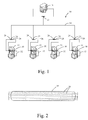
Figure 1 is a schematic diagram of a gaming system in accordance with an embodiment of the present invention; -
Figure 2 is a diagrammatic representation of a communications link of the gaming system shown inFigure 1 ; and -
Figure 3 is a diagrammatic representation of a gaming machine of the gaming system shown inFigure 1 . - Referring to the drawings, there is shown a
gaming system 10 comprising a plurality ofgaming machines 12 connected through anetwork 14 to agaming server 16. - Typically, the gaming server will be arranged to host a database and software services for use by the
gaming machines 12, and to collect data from thegaming machines 12 for storage on the database and subsequent processing. - The
network 14 includes acommunications link 18 which in this example is in the form of a Cat 5E or Cat 6 cable havingseveral communication wires 20 arranged in twisted pairs. - The
gaming system 10 also includes ajoiner 22 used to supply respective first and second server signals to each requiredcommunication wire 20 of thecommunications link 18 from thegaming server 16. In this example, the first server signals correspond to RS485 or RS422 interface standard signals and the second server signals correspond to Ethernet signals. Accordingly, thejoiner 22 in this example comprises an Ethernet connector and a RS232 or RS485 connector and is arranged to join respective connections of the Ethernet connector and the RS232 or RS485 connector together at thecommunication wires 20. - Each of the
gaming machines 12 also includes a communications module in the form of a Player Marketing Module (PMM) 30 which is arranged to facilitate communications between thegaming machine 12 and thegaming server 16. In the present example, thePMM 30 is in the form of a Sentinel III device available from Aristocrat Technologies Australia Pty Ltd. - Each of the
gaming machines 12 is associated with asplitter 24 which is arranged to split communication signals from eachcommunication wire 20 so as to provide thePMM 30 with first andsecond signal sources communication wire 20 used, afirst signal source 24 being for reception of the first server signals corresponding to RS485 or RS422 standards and thesecond signal source 26 being for reception of the second server signals corresponding to Ethernet standards. Thesplitter 24 in this example is arranged to terminate thecommunication wires 20 with an Ethernet connector and a RS232 or RS485 connector such that eachrespective communication wire 20 is electrically connected to an electrical contact in the Ethernet connector and the RS232 or RS485 connector. - It will be understood that by passing both conventional relatively low speed signals and improved relatively high speed signals over the same physical wires a relatively high bandwidth network suitable for future functionality can be produced without sacrificing the existing conventional network. This results in reduced costs because PMM software elements designed for the existing network remain unaltered and will continue to operate until functionality is available for the high speed signals. Such new functionality requiring the benefits of a relatively high bandwidth network can be developed in isolation. In addition, since additional cables are not required, new functionality can be introduced to existing networked gaming systems with minimal interruption to existing infrastructure, in particular without the need to re-cable the gaming floor.
- It will also be understood that although the
joiner 22 and thesplitters 24 are shown inFigure 1 separate to therespective server 16 and thegaming machines 12, other variations are possible. For example, thejoiner 22 may be incorporated into thegaming server 16 and each of thesplitters 24 may be incorporated into aPMM 30. - Furthermore, it will be understood that although the
joiner 22 is described above in relation to a device which receives first and second signals from theserver 16 and supplies both signals to acommunications wire 20 of thecommunications link 18, thejoiner 22 will also perform a splitter function in that communications from one or more of thePMMs 30 to theserver 16 are split so as to provide thegaming server 16 with two signal sources, for example for use by separate RS485/RS422 or Ethernet components. Similarly, while thesplitters 24 are described in relation to a device which performs a splitting function, it will be understood that thesplitters 24 may also perform a joining function in that communications from each of thePMMs 30 to thegaming server 16 are joined and supplied to arespective communications wire 20 of thecommunications link 18. - It will also be understood that although the above example is described in relation to a gaming system which comprises one server arranged to provide both conventional RS485/RS422 signals and Ethernet signals, other variations are possible. For example, two gaming servers may be provided, a first gaming server which uses RS485/RS422 type signs and a second gaming server which uses Ethernet signals.
- An
example gaming machine 12 is illustrated inFigure 3 . Thegaming machine 12 includes aconsole 42 incorporating the PlayerMarketing Module 30 and has adisplay 44 on which is displayed representations of agame 46 that can be played by a player. Amid-trim 50 of thegaming machine 12 houses a bank ofbuttons 52 for enabling a player to interact with the gaming machine, in particular during gameplay. Themid-trim 50 also houses acredit input mechanism 54 which in this example includes acoin input chute 54A and abill collector 54B. Other credit input mechanisms may also be employed, for example, a card reader for reading a smart card, debit card or credit card. ThePMM 30 may include a reading device (not shown) for the purpose of reading a player tracking device, for example as part of a loyalty program. The player tracking device may be in the form of a card, flash drive or any other portable storage medium capable of being read by the reading device. - A
top box 56 may carryartwork 58, including for example pay tables and details of bonus awards and other information or images relating to the game. Further artwork and/or information may be provided on afront panel 59 of theconsole 42. Acoin tray 60 is mounted beneath thefront panel 59 for dispensing cash payouts from thegaming machine 12. - The
display 44 is in the form of a video display unit, particularly a cathode ray tube screen device. Alternatively, thedisplay 44 may be a liquid crystal display, plasma screen, or any other suitable video display unit. Thetop box 56 may also include a display, for example a video display unit, which may be of the same type as thedisplay 44, or of a different type. - The
display 44 in this example is arranged to display representations of several reels, each reel of which has several associated symbols. Typically 3, 4 or 5 reels are provided. During operation of the game, the reels first appear to rotate then stop with typically three symbols visible on each reel. Game outcomes are determined on the basis of the visible symbols together with any special functions associated with the symbols, and if a function has been allocated to a reel, on the basis of the allocated function. - Modifications and variations as would be apparent to a skilled addressee are deemed to be within the scope of the present invention.
Claims (18)
- A gaming system comprising:a gaming communications module arranged to communicate with at least one gaming server through a communications link having at least one communication wire; andat least one splitter device in communication with the gaming communications module and arranged during use to provide the gaming communications module with two signal sources from the or each communication wire, one of the signal sources being for reception of first server signals at the gaming communications module from a gaming server, and the other of the signal sources being for reception of second server signals at the gaming communications module from the gaming server.
- A gaming system as claimed in claim 1, comprising at least one gaming server and a communications link between the at least one gaming communications module and the gaming server for facilitating communications between the gaming server and the at least one gaming communications module, the communications link including at least one communication wire and the gaming server being arranged to supply first and second server signals to the communication wire from the gaming server.
- A gaming system as claimed in claim 1 or claim 2, wherein the gaming system includes at least one joining device arranged to supply first and second server signals to the communication wire.
- A gaming system as claimed in any one of claims 1 to 3, wherein the splitter device is either:• separate from and connectable to the gaming communications module, or;• incorporated into the gaming communications module.
- A gaming system as claimed in claim 3, wherein the joiner device is either:• separate from and connectable to the gaming server, or;• incorporated into the gaming server.
- A gaming system as claimed in any one of the preceding claims, wherein the first server signals conform to RS485 or RS422 interface standards.
- A gaming system as claimed in any one of the preceding claims, wherein the second signals conform to Ethernet standards.
- A gaming system as claimed in any one of the preceding claims, wherein communications link is a Cat 5E or Cat 6 cable.
- A gaming system as claimed in any one of the preceding claims, wherein the communications link includes a plurality of communication wires and the splitter device is arranged to provide the gaming communications module with two signal sources for each of the communication wires.
- A gaming server arranged to supply first and second server signals to a gaming communications module through a communications link having at least one communication wire, the gaming server comprising:at least one joining device arranged to supply first and second server signals to the communication wire.
- A method of gaming comprising:providing a gaming communications module;communicating with at least one gaming server through a communications link having at least one communication wire;splitting communications from the communication link so as to provide the gaming communications module with two signal sources from the or each communication wire, one of the signal sources being for reception of first server signals at the gaming communications module from a gaming server, and the other of the signal sources being for reception of second server signals at the gaming communications module from the gaming server.
- A method as claimed in claim 11, comprising providing at least one joining device for supplying first and second server signals to the at least one communication wire.
- A method as claimed in claim 11 or claim 12, comprising providing a splitter device that is either:• separate from and connectable to the gaming communications module, or• incorporated into the gaming communications module.
- A method as claimed in claim 12,wherein said at least one joiner device is either:• separate from and connectable to the gaming server, or• incorporated into the gaming server.
- A method as claimed in any one of claims 11 to 14, wherein the first server signals conform to RS485 or RS422 interface standards.
- A method as claimed in any one of claims 11 to 15, wherein the second signals conform to Ethernet standards.
- A method as claimed in any one of claims 11 to 16, wherein communications link is a Cat 5E or Cat 6 cable.
- A method as claimed in any one of claims 11 to 17, comprising providing the communications link with a plurality of communication wires and arranging the splitter device to provide the gaming communications module with two signal sources for each of the communication wires.
Applications Claiming Priority (1)
| Application Number | Priority Date | Filing Date | Title |
|---|---|---|---|
| AU2007902532A AU2007902532A0 (en) | 2007-05-11 | A gaming system |
Publications (2)
| Publication Number | Publication Date |
|---|---|
| EP1990783A2 true EP1990783A2 (en) | 2008-11-12 |
| EP1990783A3 EP1990783A3 (en) | 2009-06-03 |
Family
ID=39680941
Family Applications (1)
| Application Number | Title | Priority Date | Filing Date |
|---|---|---|---|
| EP08155106A Withdrawn EP1990783A3 (en) | 2007-05-11 | 2008-04-24 | Gaming system |
Country Status (3)
| Country | Link |
|---|---|
| US (1) | US20090093308A1 (en) |
| EP (1) | EP1990783A3 (en) |
| AU (1) | AU2008201509B2 (en) |
Citations (4)
| Publication number | Priority date | Publication date | Assignee | Title |
|---|---|---|---|---|
| WO2000003518A1 (en) * | 1998-07-10 | 2000-01-20 | Upstate Systems Tec, Inc., Doing Business As Ustec | Single medium wiring scheme for multiple signal distribution in building and access port therefor |
| US20030100369A1 (en) * | 2001-11-23 | 2003-05-29 | Cyberscan Technology, Inc. | Modular entertainment and gaming systems configured to consume and provide network services |
| EP1458062A2 (en) * | 2003-03-14 | 2004-09-15 | Tyco Electronics Corporation | Electrical coupler with splitting receptacle jack interfaces |
| US20070060366A1 (en) * | 2005-09-12 | 2007-03-15 | Morrow James W | Hybrid network system and method |
Family Cites Families (16)
| Publication number | Priority date | Publication date | Assignee | Title |
|---|---|---|---|---|
| US4849794A (en) * | 1986-07-18 | 1989-07-18 | Micro-Radiographs, Inc. | High precision photoreduction process and related apparatus |
| US5024512A (en) * | 1986-07-18 | 1991-06-18 | American Photo Systems, Inc. | Microfilm reader with microfilm and reticle images provided to each of two binocular eyepieces |
| DE3641949C1 (en) * | 1986-12-09 | 1988-05-26 | Kugelfischer G Schaefer & Co | Device for evaluating radio photoluminescent glasses |
| US5133029A (en) * | 1991-06-28 | 1992-07-21 | Bell Communications Research, Inc. | Adiabatic polarization splitter |
| US5189295A (en) * | 1991-08-30 | 1993-02-23 | Edo Corporation, Barnes Engineering Division | Three axis earth/star sensor |
| CA2116874A1 (en) * | 1991-09-06 | 1993-03-18 | Christopher Joseph Cantrall | Optical methods and apparatus |
| US5453043A (en) * | 1994-04-04 | 1995-09-26 | Monson; Keith W. | Pelvic splitter device and method of use thereof |
| US6226296B1 (en) * | 1997-01-16 | 2001-05-01 | Physical Optics Corporation | Metropolitan area network switching system and method of operation thereof |
| US20020045477A1 (en) * | 1999-08-03 | 2002-04-18 | Dabrowski Stanley P. | Method and apparatus for scrip distribution and management permitting redistribution of issued scrip |
| JP3385328B2 (en) * | 1999-07-30 | 2003-03-10 | 独立行政法人通信総合研究所 | Optical parametric oscillator |
| US6280312B1 (en) * | 2000-03-29 | 2001-08-28 | Geoff Elrod | Pelvic bone splitter, particularly for deer |
| US20040147326A1 (en) * | 2003-01-14 | 2004-07-29 | Stiles Thomas William | Gaming device system |
| US20050076092A1 (en) * | 2003-10-02 | 2005-04-07 | Sony Corporation And Sony Electronics Inc. | User shared virtual channel via media storage |
| US20050139776A1 (en) * | 2003-12-29 | 2005-06-30 | Reiter Eric S. | Photon violation spectroscopy |
| US20060197914A1 (en) * | 2005-03-04 | 2006-09-07 | Colorlink, Inc. | Four panel projection system |
| US20060277254A1 (en) * | 2005-05-02 | 2006-12-07 | Kenoyer Michael L | Multi-component videoconferencing system |
-
2008
- 2008-04-02 AU AU2008201509A patent/AU2008201509B2/en active Active
- 2008-04-24 EP EP08155106A patent/EP1990783A3/en not_active Withdrawn
- 2008-05-09 US US12/118,102 patent/US20090093308A1/en not_active Abandoned
Patent Citations (4)
| Publication number | Priority date | Publication date | Assignee | Title |
|---|---|---|---|---|
| WO2000003518A1 (en) * | 1998-07-10 | 2000-01-20 | Upstate Systems Tec, Inc., Doing Business As Ustec | Single medium wiring scheme for multiple signal distribution in building and access port therefor |
| US20030100369A1 (en) * | 2001-11-23 | 2003-05-29 | Cyberscan Technology, Inc. | Modular entertainment and gaming systems configured to consume and provide network services |
| EP1458062A2 (en) * | 2003-03-14 | 2004-09-15 | Tyco Electronics Corporation | Electrical coupler with splitting receptacle jack interfaces |
| US20070060366A1 (en) * | 2005-09-12 | 2007-03-15 | Morrow James W | Hybrid network system and method |
Also Published As
| Publication number | Publication date |
|---|---|
| EP1990783A3 (en) | 2009-06-03 |
| AU2008201509A1 (en) | 2008-11-27 |
| US20090093308A1 (en) | 2009-04-09 |
| AU2008201509B2 (en) | 2011-09-08 |
Similar Documents
| Publication | Publication Date | Title |
|---|---|---|
| AU2022283788B2 (en) | Personal Electronic Device for Gaming and Bonus System | |
| US9547954B2 (en) | Associating mobile device with electronic gaming machine | |
| US7247098B1 (en) | Combination fingerprint reader and I/O devices for gaming machines | |
| US7951002B1 (en) | Using a gaming machine as a server | |
| US6884173B2 (en) | Configuration technique for a gaming machine | |
| US8672757B2 (en) | Gaming device with attached audio-capable chair | |
| US10140814B2 (en) | Mobile payment and credit integration into a wagering game machine | |
| US20080194329A1 (en) | Method And Apparatus For Gaming Machine Peripherals | |
| US20100081500A1 (en) | Gaming system and a gaming peripheral | |
| AU2008201509B2 (en) | A gaming system | |
| SG182055A1 (en) | Gaming system with server-centric architecture | |
| AU2011226851A1 (en) | A gaming system | |
| AU2009200139B2 (en) | A method of processing a user data card, an interface module and a gaming system | |
| AU2011250701B2 (en) | A Gaming System and a Method of Gaming | |
| AU2013200411B2 (en) | Electronic gaming machine monitor with universal gaming adaptor capabilities | |
| AU2017202650B2 (en) | A gaming system and a gaming peripheral | |
| US20110250963A1 (en) | gaming system | |
| AU2012200531B2 (en) | A method of processing a user data card, an interface module and a gaming system | |
| US20080261700A1 (en) | Gaming Device Including Configurable Communication Unit | |
| AU2020210263A1 (en) | A gaming system | |
| AU2019201092A1 (en) | A Gaming System and a Method of Gaming | |
| AU2012202935A1 (en) | A gaming system and a gaming peripheral |
Legal Events
| Date | Code | Title | Description |
|---|---|---|---|
| PUAI | Public reference made under article 153(3) epc to a published international application that has entered the european phase |
Free format text: ORIGINAL CODE: 0009012 |
|
| AK | Designated contracting states |
Kind code of ref document: A2 Designated state(s): AT BE BG CH CY CZ DE DK EE ES FI FR GB GR HR HU IE IS IT LI LT LU LV MC MT NL NO PL PT RO SE SI SK TR |
|
| AX | Request for extension of the european patent |
Extension state: AL BA MK RS |
|
| PUAL | Search report despatched |
Free format text: ORIGINAL CODE: 0009013 |
|
| AK | Designated contracting states |
Kind code of ref document: A3 Designated state(s): AT BE BG CH CY CZ DE DK EE ES FI FR GB GR HR HU IE IS IT LI LT LU LV MC MT NL NO PL PT RO SE SI SK TR |
|
| AX | Request for extension of the european patent |
Extension state: AL BA MK RS |
|
| AKX | Designation fees paid | ||
| REG | Reference to a national code |
Ref country code: DE Ref legal event code: 8566 |
|
| STAA | Information on the status of an ep patent application or granted ep patent |
Free format text: STATUS: THE APPLICATION IS DEEMED TO BE WITHDRAWN |
|
| 18D | Application deemed to be withdrawn |
Effective date: 20091204 |