EP1992307A1 - Dental saliva ejection pump - Google Patents
Dental saliva ejection pump Download PDFInfo
- Publication number
- EP1992307A1 EP1992307A1 EP08386007A EP08386007A EP1992307A1 EP 1992307 A1 EP1992307 A1 EP 1992307A1 EP 08386007 A EP08386007 A EP 08386007A EP 08386007 A EP08386007 A EP 08386007A EP 1992307 A1 EP1992307 A1 EP 1992307A1
- Authority
- EP
- European Patent Office
- Prior art keywords
- liquids
- valve
- tank
- oil
- oil flow
- Prior art date
- Legal status (The legal status is an assumption and is not a legal conclusion. Google has not performed a legal analysis and makes no representation as to the accuracy of the status listed.)
- Withdrawn
Links
Images
Classifications
-
- A—HUMAN NECESSITIES
- A61—MEDICAL OR VETERINARY SCIENCE; HYGIENE
- A61C—DENTISTRY; APPARATUS OR METHODS FOR ORAL OR DENTAL HYGIENE
- A61C17/00—Devices for cleaning, polishing, rinsing or drying teeth, teeth cavities or prostheses; Saliva removers; Dental appliances for receiving spittle
-
- A—HUMAN NECESSITIES
- A61—MEDICAL OR VETERINARY SCIENCE; HYGIENE
- A61C—DENTISTRY; APPARATUS OR METHODS FOR ORAL OR DENTAL HYGIENE
- A61C17/00—Devices for cleaning, polishing, rinsing or drying teeth, teeth cavities or prostheses; Saliva removers; Dental appliances for receiving spittle
- A61C17/06—Saliva removers; Accessories therefor
- A61C17/12—Control devices, e.g. for suction
-
- A—HUMAN NECESSITIES
- A61—MEDICAL OR VETERINARY SCIENCE; HYGIENE
- A61C—DENTISTRY; APPARATUS OR METHODS FOR ORAL OR DENTAL HYGIENE
- A61C1/00—Dental machines for boring or cutting ; General features of dental machines or apparatus, e.g. hand-piece design
- A61C1/0061—Air and water supply systems; Valves specially adapted therefor
- A61C1/0084—Supply units, e.g. reservoir arrangements, specially adapted pumps
- A61C1/0092—Pumps specially adapted therefor
Definitions
- the present invention is referring to a Dental Saliva Ejection Pump, which is used for the intake and removal of any excess liquid, present in the patient's mouth, during dental, surgical or other, operations.
- Saliva ejection pumps are usually embedded in the main dentist's deck and they operate either by compressed air provided by separate compressors, or by other external equipment, that are adapted to the main deck by specialized technicians. These pumps appear to have many weak points that prove to be inconvenient: They are prone to breakdowns, the compressor is noisy and consumes a lot of electrical power, and they require authorized personnel for their maintenance and repair.
- the saliva ejection pump of the present invention has many features: It has small dimensions and operates independently from the main dentist's deck, with low power consumption and operating noise, negligible lubricant oil consumption, very simple operation and maintenance functions, without critical points of extreme fatigue, which results in long term reliability.
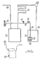
- It consists of a small electric pump (1), a liquids collection tank (2), a liquids discharge siphon (3), a small lubricant oil container (4), cooling coil (5) for oil/air and some other ancillary components.
- the vacuum created by the pump (1) aspirates the liquids from the patient's mouth along with air, through the air intake pipe (10), and drives them into the liquids collection tank (2) and through the liquids discharge siphon (3) to the drainage.
- the oil (19) in-taken from the container (4) is inserted into the pump (1) along with air from the air intake pipe (10), lubricating and cooling the pump, and then is returned to the container (4) through the coil (5) where it is cooled to ambient temperature, preventing the creation and release of odours to the environment.
- the oil flow limiter valve (7) inside the oil container (4), regulates the oil flow by means of the small ball (22), depending on the existing suction power.
- the oil flow visual inspection valve (8) creates small air bubbles in the oil flowing through the transparent pipe (23), making the oil flow easily observable.
- the suction limiter valve (9) regulates the vacuum created by the pump (1), in order to sustain the intake rate from the patient's mouth and keeping it from reaching excess, not comfortable, levels.
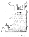
- the liquids collection tank (2) has the following operation:
- the vacuum created by the pump (1) inside the tank is keeping the liquids output valve (13), at the discharge siphon (3), closed, until the liquids level in the tank reaches a specific point where their hydrostatic pressure equalizes the vacuum closing force and the output valve (13) finally opens, releasing the liquids from the siphon (3) to the drainage (24).
- the valve (13) opens also if the floater (11) in the tank is raised, by the liquids, to a certain level and then, the liquids level valve (12) opens momentarily, the vacuum level in the tank is decreased and the liquids are finally discharged to the drainage. In such case, a short duration sound is created by the buzzer (16), which is activated from the magnetic contacts (15), in the proximity of the floater's magnet (14). The liquids are also released to the drainage by turning off the devise. Cleaning the tank is easily carried out, through the cleaning cap (18).
Abstract
Description
- The present invention is referring to a Dental Saliva Ejection Pump, which is used for the intake and removal of any excess liquid, present in the patient's mouth, during dental, surgical or other, operations.
- Saliva ejection pumps are usually embedded in the main dentist's deck and they operate either by compressed air provided by separate compressors, or by other external equipment, that are adapted to the main deck by specialized technicians. These pumps appear to have many weak points that prove to be inconvenient: They are prone to breakdowns, the compressor is noisy and consumes a lot of electrical power, and they require authorized personnel for their maintenance and repair.
- The saliva ejection pump of the present invention has many features: It has small dimensions and operates independently from the main dentist's deck, with low power consumption and operating noise, negligible lubricant oil consumption, very simple operation and maintenance functions, without critical points of extreme fatigue, which results in long term reliability.
- It consists of a small electric pump (1), a liquids collection tank (2), a liquids discharge siphon (3), a small lubricant oil container (4), cooling coil (5) for oil/air and some other ancillary components.
- A description of the present invention follows, with reference to the drawings attached.
-
Figure 1 shows the connection of the electric pump (1) with the lubricant oil container (4), the cooling coil (5), the oil flow control valve (6), the oil flow limiter valve (7), the oil flow visual inspection valve (8), the suction limiter valve (9) and the air intake pipe (10). -
Figure 2 shows the liquids collection tank (2), the liquids discharge siphon (3), the floater (11) with the liquids level valve (12), the liquids output valve (13), the magnet (14) with the magnetic contacts (15), the buzzer (16), the suction hose tip (17), the cleaning cap (18) and the air intake pipe (10) from the pump (1). - A description of the operation of the present invention follows:
- The vacuum created by the pump (1) aspirates the liquids from the patient's mouth along with air, through the air intake pipe (10), and drives them into the liquids collection tank (2) and through the liquids discharge siphon (3) to the drainage. The oil (19) in-taken from the container (4), is inserted into the pump (1) along with air from the air intake pipe (10), lubricating and cooling the pump, and then is returned to the container (4) through the coil (5) where it is cooled to ambient temperature, preventing the creation and release of odours to the environment.
- The oil flow limiter valve (7), inside the oil container (4), regulates the oil flow by means of the small ball (22), depending on the existing suction power. The oil flow visual inspection valve (8) creates small air bubbles in the oil flowing through the transparent pipe (23), making the oil flow easily observable.
- The suction limiter valve (9) regulates the vacuum created by the pump (1), in order to sustain the intake rate from the patient's mouth and keeping it from reaching excess, not comfortable, levels.
- The liquids collection tank (2) has the following operation:
- The vacuum created by the pump (1) inside the tank, is keeping the liquids output valve (13), at the discharge siphon (3), closed, until the liquids level in the tank reaches a specific point where their hydrostatic pressure equalizes the vacuum closing force and the output valve (13) finally opens, releasing the liquids from the siphon (3) to the drainage (24). The valve (13) opens also if the floater (11) in the tank is raised, by the liquids, to a certain level and then, the liquids level valve (12) opens momentarily, the vacuum level in the tank is decreased and the liquids are finally discharged to the drainage. In such case, a short duration sound is created by the buzzer (16), which is activated from the magnetic contacts (15), in the proximity of the floater's magnet (14). The liquids are also released to the drainage by turning off the devise. Cleaning the tank is easily carried out, through the cleaning cap (18).
- Production of the said devise is easily accomplished by the use of standard commercial components.
Claims (3)
- Dental saliva ejection pump comprising a small electric pump (1), a liquids collection tank (2), a liquids discharge siphon (3), a lubricant oil container (4), cooling coil (5) for oil/air, oil flow control valve (6), oil flow limiter valve (7), oil flow visual inspection valve (8), liquids level valve (12), and liquids output valve (13).
- Dental saliva ejection pump, as recited in claim 1, which includes a tank (2) where the liquids are collected by means of the vacuum created by the electric pump (1) and depending on the liquids level and the vacuum level inside the tank (2), the output valve (13), located in the siphon (3), opens, releasing the liquids to the drainage.
- Dental saliva ejection pump, as recited in claim 2, which is characterized by the fact that the tank (2) is protected from liquids overflow by means of the floater (11) and the liquids level valve (12), and, the electric pump (1) is protected from overheating, through lubricant oil circulation, contained in the oil container (4), which is cooled by passing through the cooling coil (5), while its flow is controlled by the oil flow limiter valve (7) and the oil flow visual inspection valve (8).
Applications Claiming Priority (1)
| Application Number | Priority Date | Filing Date | Title |
|---|---|---|---|
| GR20070100297A GR1005961B (en) | 2007-05-17 | 2007-05-17 | Dentist's surgery saliva pump. |
Publications (1)
| Publication Number | Publication Date |
|---|---|
| EP1992307A1 true EP1992307A1 (en) | 2008-11-19 |
Family
ID=39240866
Family Applications (1)
| Application Number | Title | Priority Date | Filing Date |
|---|---|---|---|
| EP08386007A Withdrawn EP1992307A1 (en) | 2007-05-17 | 2008-05-15 | Dental saliva ejection pump |
Country Status (2)
| Country | Link |
|---|---|
| EP (1) | EP1992307A1 (en) |
| GR (1) | GR1005961B (en) |
Cited By (1)
| Publication number | Priority date | Publication date | Assignee | Title |
|---|---|---|---|---|
| CN111888013A (en) * | 2020-07-31 | 2020-11-06 | 宁波市海曙莱富医疗科技有限公司 | Dental handpiece oiling machine |
Citations (3)
| Publication number | Priority date | Publication date | Assignee | Title |
|---|---|---|---|---|
| US4963094A (en) * | 1987-04-13 | 1990-10-16 | Ramvac Corp. | Vacuum controller and filter assembly for dental vacuum system |
| US5282744A (en) * | 1983-03-21 | 1994-02-01 | Meyer Robert A | Dental vacuum pump system |
| EP1366728A1 (en) * | 2002-05-27 | 2003-12-03 | Ezio Bartocci | Surgical draining apparatus, in particular for a dental surgery |
-
2007
- 2007-05-17 GR GR20070100297A patent/GR1005961B/en active IP Right Grant
-
2008
- 2008-05-15 EP EP08386007A patent/EP1992307A1/en not_active Withdrawn
Patent Citations (3)
| Publication number | Priority date | Publication date | Assignee | Title |
|---|---|---|---|---|
| US5282744A (en) * | 1983-03-21 | 1994-02-01 | Meyer Robert A | Dental vacuum pump system |
| US4963094A (en) * | 1987-04-13 | 1990-10-16 | Ramvac Corp. | Vacuum controller and filter assembly for dental vacuum system |
| EP1366728A1 (en) * | 2002-05-27 | 2003-12-03 | Ezio Bartocci | Surgical draining apparatus, in particular for a dental surgery |
Cited By (1)
| Publication number | Priority date | Publication date | Assignee | Title |
|---|---|---|---|---|
| CN111888013A (en) * | 2020-07-31 | 2020-11-06 | 宁波市海曙莱富医疗科技有限公司 | Dental handpiece oiling machine |
Also Published As
| Publication number | Publication date |
|---|---|
| GR1005961B (en) | 2008-06-27 |
Similar Documents
| Publication | Publication Date | Title |
|---|---|---|
| EP2258948A3 (en) | Improved refrigerant compressor | |
| EP2158926A3 (en) | Aspirator assembly | |
| EP1614983A3 (en) | Air conditioner | |
| EP1950512A1 (en) | Automatic gas discharging device for lithium-bromid machine and method thereof | |
| EP1992307A1 (en) | Dental saliva ejection pump | |
| ATE314572T1 (en) | EXTRACTION UNIT WITH HEATING DEVICE AND HEAT EXCHANGER EXTENSION, FOR A TANK WITH PRECIPITATIVE AND/OR FREEZING FLUID | |
| CN201235140Y (en) | Automatic pollution discharge aspirator | |
| EP1902657A3 (en) | Dishwasher with an air-break and method of controlling the same | |
| KR20120134268A (en) | Suction system by vaccum pump in dental clinic | |
| EP4079344A2 (en) | Disposable thrombectomy maceration and aspiration system | |
| CN214329153U (en) | Vacuum collection and discharge device | |
| CN2585991Y (en) | Self-priming device of centrifugal pump | |
| CN2621684Y (en) | Drainage device | |
| CN207286374U (en) | A kind of pleural cavity closed drainage device with warning function | |
| CN217091568U (en) | Multifunctional liquid collecting container | |
| CN205145212U (en) | Suction device of central authorities | |
| US8534229B2 (en) | Pump-assisted gravel vacuum | |
| CN215134203U (en) | Suction bottle for endoscope and endoscope main unit provided with same | |
| JPH11351603A (en) | Drain-suction type air conditioner | |
| CN217548607U (en) | Supply and recovery device | |
| CN2582640Y (en) | Negative pressure suction bottle cap capable of preventing reverse suction drainage | |
| JP4750434B2 (en) | Spraying equipment | |
| KR101159294B1 (en) | A method controlling for draining of a bodyfluid drainage apparatus | |
| JP4083540B2 (en) | Pump equipment with siphon break device | |
| CN116421086A (en) | Hand-held skin cleaning device |
Legal Events
| Date | Code | Title | Description |
|---|---|---|---|
| PUAI | Public reference made under article 153(3) epc to a published international application that has entered the european phase |
Free format text: ORIGINAL CODE: 0009012 |
|
| AK | Designated contracting states |
Kind code of ref document: A1 Designated state(s): AT BE BG CH CY CZ DE DK EE ES FI FR GB GR HR HU IE IS IT LI LT LU LV MC MT NL NO PL PT RO SE SI SK TR |
|
| AX | Request for extension of the european patent |
Extension state: AL BA MK RS |
|
| 17P | Request for examination filed |
Effective date: 20090209 |
|
| 17Q | First examination report despatched |
Effective date: 20090320 |
|
| AKX | Designation fees paid |
Designated state(s): AT BE BG CH CY CZ DE DK EE ES FI FR GB GR HR HU IE IS IT LI LT LU LV MC MT NL NO PL PT RO SE SI SK TR |
|
| STAA | Information on the status of an ep patent application or granted ep patent |
Free format text: STATUS: THE APPLICATION IS DEEMED TO BE WITHDRAWN |
|
| 18D | Application deemed to be withdrawn |
Effective date: 20101201 |