EP1992389A1 - Improved sports sensor - Google Patents
Improved sports sensor Download PDFInfo
- Publication number
- EP1992389A1 EP1992389A1 EP08156407A EP08156407A EP1992389A1 EP 1992389 A1 EP1992389 A1 EP 1992389A1 EP 08156407 A EP08156407 A EP 08156407A EP 08156407 A EP08156407 A EP 08156407A EP 1992389 A1 EP1992389 A1 EP 1992389A1
- Authority
- EP
- European Patent Office
- Prior art keywords
- data
- accelerometer
- gps
- acquisition system
- acceleration
- Prior art date
- Legal status (The legal status is an assumption and is not a legal conclusion. Google has not performed a legal analysis and makes no representation as to the accuracy of the status listed.)
- Ceased
Links
Images


Classifications
-
- A—HUMAN NECESSITIES
- A63—SPORTS; GAMES; AMUSEMENTS
- A63B—APPARATUS FOR PHYSICAL TRAINING, GYMNASTICS, SWIMMING, CLIMBING, OR FENCING; BALL GAMES; TRAINING EQUIPMENT
- A63B24/00—Electric or electronic controls for exercising apparatus of preceding groups; Controlling or monitoring of exercises, sportive games, training or athletic performances
- A63B24/0021—Tracking a path or terminating locations
-
- A—HUMAN NECESSITIES
- A63—SPORTS; GAMES; AMUSEMENTS
- A63B—APPARATUS FOR PHYSICAL TRAINING, GYMNASTICS, SWIMMING, CLIMBING, OR FENCING; BALL GAMES; TRAINING EQUIPMENT
- A63B69/00—Training appliances or apparatus for special sports
- A63B69/10—Swimming instruction apparatus for use without water
-
- A—HUMAN NECESSITIES
- A63—SPORTS; GAMES; AMUSEMENTS
- A63B—APPARATUS FOR PHYSICAL TRAINING, GYMNASTICS, SWIMMING, CLIMBING, OR FENCING; BALL GAMES; TRAINING EQUIPMENT
- A63B24/00—Electric or electronic controls for exercising apparatus of preceding groups; Controlling or monitoring of exercises, sportive games, training or athletic performances
- A63B24/0021—Tracking a path or terminating locations
- A63B2024/0025—Tracking the path or location of one or more users, e.g. players of a game
-
- A—HUMAN NECESSITIES
- A63—SPORTS; GAMES; AMUSEMENTS
- A63B—APPARATUS FOR PHYSICAL TRAINING, GYMNASTICS, SWIMMING, CLIMBING, OR FENCING; BALL GAMES; TRAINING EQUIPMENT
- A63B2220/00—Measuring of physical parameters relating to sporting activity
- A63B2220/10—Positions
- A63B2220/12—Absolute positions, e.g. by using GPS
-
- A—HUMAN NECESSITIES
- A63—SPORTS; GAMES; AMUSEMENTS
- A63B—APPARATUS FOR PHYSICAL TRAINING, GYMNASTICS, SWIMMING, CLIMBING, OR FENCING; BALL GAMES; TRAINING EQUIPMENT
- A63B2220/00—Measuring of physical parameters relating to sporting activity
- A63B2220/10—Positions
- A63B2220/13—Relative positions
-
- A—HUMAN NECESSITIES
- A63—SPORTS; GAMES; AMUSEMENTS
- A63B—APPARATUS FOR PHYSICAL TRAINING, GYMNASTICS, SWIMMING, CLIMBING, OR FENCING; BALL GAMES; TRAINING EQUIPMENT
- A63B2220/00—Measuring of physical parameters relating to sporting activity
- A63B2220/10—Positions
- A63B2220/16—Angular positions
-
- A—HUMAN NECESSITIES
- A63—SPORTS; GAMES; AMUSEMENTS
- A63B—APPARATUS FOR PHYSICAL TRAINING, GYMNASTICS, SWIMMING, CLIMBING, OR FENCING; BALL GAMES; TRAINING EQUIPMENT
- A63B2220/00—Measuring of physical parameters relating to sporting activity
- A63B2220/30—Speed
-
- A—HUMAN NECESSITIES
- A63—SPORTS; GAMES; AMUSEMENTS
- A63B—APPARATUS FOR PHYSICAL TRAINING, GYMNASTICS, SWIMMING, CLIMBING, OR FENCING; BALL GAMES; TRAINING EQUIPMENT
- A63B2220/00—Measuring of physical parameters relating to sporting activity
- A63B2220/40—Acceleration
-
- A—HUMAN NECESSITIES
- A63—SPORTS; GAMES; AMUSEMENTS
- A63B—APPARATUS FOR PHYSICAL TRAINING, GYMNASTICS, SWIMMING, CLIMBING, OR FENCING; BALL GAMES; TRAINING EQUIPMENT
- A63B69/00—Training appliances or apparatus for special sports
- A63B69/0028—Training appliances or apparatus for special sports for running, jogging or speed-walking
-
- A—HUMAN NECESSITIES
- A63—SPORTS; GAMES; AMUSEMENTS
- A63B—APPARATUS FOR PHYSICAL TRAINING, GYMNASTICS, SWIMMING, CLIMBING, OR FENCING; BALL GAMES; TRAINING EQUIPMENT
- A63B69/00—Training appliances or apparatus for special sports
- A63B69/16—Training appliances or apparatus for special sports for cycling, i.e. arrangements on or for real bicycles
Definitions
- This invention relates to an improved method and system for monitoring performance characteristics of athletes and in particular the particular movements which contribute to enhanced performance.
- the ability to measure and record athlete physiological information and positional information associated with athlete movement in real-time is critical in the process of athlete training and coaching. Blood oxygen, respiration, heart rates, velocity, acceleration/force, changes in direction, and position and many other factors are required in elite athlete training and coaching.
- the position, movement and force information plays an important role in effective analysis of the athlete performance, especially for rowers.
- the stroke frequency, force and synchronisation of athletes are critical for the performance of the rowers in a competition.
- the stroke information can only be measured in either dedicated sports laboratories or using simulated devices. Reliable analysis of the stroke rate and stroke distance in rowing has been a challenge for a long time due to the availability of the real scenario data, in particular a high precision of position, velocity and acceleration data.
- USA patents 4984986 and 5099689 disclose measuring systems for off water rowing apparatus which measure the number of strokes or the force applied to the machine.
- USA patent 6308649 discloses a monitoring system for sail boat racing which provides feedback to the crew of such parameters as wind speed and direction boat speed, sail boat comfort parameters , sail shape, line tensions, rudder angle etc.
- USA 6148262 discloses a bike mounted sports computer including a GPS receiver to provide a mapping facility.
- W02004/039462 discloses a sensor for rowing which combines a GPS sensor with a three dimensional accelerometer.
- the present invention provides a data acquisition system for use in sporting events which incorporates
- This device will provide longitudinal data from the training and competition environment and provide both athlete physiological data and performance data related to the sport.
- the number of inertial sensors measuring angular acceleration will depend on the number of dimensions that information is required for and this will vary from sport to sport.
- a GPS receiver transmitter may be included in the device to derive location and speed parameters.
- one or more magnetometers may be included in the device to derive direction of movement which can be combined with data from the GPS and accelerometer components.
- the magnetometers can be substituted for the angular acceleration sensors (gyros).
- the magnetometers are preferable to gyroscopes. For instance to construct an inertial navigation system, you require a gravity model to separate out acceleration due to gravity. This can be determined with the gyroscopes (the traditional approach), however the magnetometers may be combined with GPS for an inertial navigation system.
- magnetometers provide a continuous 3d magnetic north vector, and the GPS gives latitude and longitude, it is possible to use the gyroscopes with GPS to construct a gravity model (remembering that a north vector in has a relationship with horizontal, depending on the latitude which is determined by the GPS. Magnetometers are usually less expensive than gyros, and the mathematics for the algorithm is much simpler enabling on the fly processing.
- Heart rate is the prime parameter to be measured and this may be sensed using electrical sensors or microphones. Respiratory rate is also important and may be measured by sensing the stretching of a chest band or using a microphone and signal recognition software.
- Another parameter is arterial oxygen saturation which may be measured non invasively by a sensor, placed on an earlobe or finger tip, using pulse oximetry employing an infra red absorption technique. Infra-red spectroscopy may be used for non invasive measurement of blood lactate concentrations.
- velocity is derived from the global position sensor or other wireless triangulation system and the accelerometer data is sampled to obtain movement characteristics of the sport being monitored.
- accelerometer data is integrated to derive velocity related movement characteristics and drift is checked every second using the output from the global position sensor.
- a display can be carried out on the sensor itself and an external computer may not be necessary.
- the device may also incorporate appropriate storage for the collected data.
- the data can be transmitted to other computers by wireless or cable transmission.
- This system provides a platform device which can be used for a wide range of sports simply by providing appropriate software to derive from the accelerometer and GPS data, the desired sport parameters such as stride frequency, velocity, stride length, vertical acceleration, time off the ground for long jumping and events such as aerial skiing or snowboarding.
- the angular acceleration sensor or gyro sensor measures angular change in up to 3 dimensions (pitch, yaw and roll) and is used to sense movements like strokes and turns in swimming or strides and loft time in running, or kicks in team sports such as football, in a similar fashion to accelerometers. Additionally the magnetometer sensors indicate direction of the movement.
- the system of this invention can be used in swimming to identify stroke type, turns, and with turns the number of laps and the stroke rate per lap as well as lap times. Careful analysis of each stroke can show the efficiency and power by comparing the acceleration and deceleration cycles and the effect of breathing cycles.
- the GPS can also be used to provide an indication of location, direction, and speed relative to the course.
- the system of this invention can be used in cycling to identify location, speed, power and heart rate.
- a magnetometer to the unit on the cyclist pedal cadence can be sensed.
- pedal cadence can be sensed by a unit on the bike and transferred to the unit on the cyclist using a radio frequency pickup unit.
- Pedal cadence can also be determined from the signals picked up from the accelerometer and the angular acceleration sensor.
- the unit In skiing the unit can detect velocity, position, and heart rate but also the power imparted by each leg and the lateral acceleration and deceleration. In jumping the unit can detect loft time and speed.
- the movement of the player can be tracked.
- the impact force of a tackle or the energy expended in routines such as rucking can be determined from the accelerometer and the angular acceleration sensor.
- the device of this invention is a modification of the device described in Australian patent applications 2003277952 and 2006222732 .
- MEMS micro-electromechanical systems
- accelerometers are used concurrently with gyroscopes to form an inertial or dead reckoning system.
- the deviation from a known starting point is determined by integration of acceleration in each axis over time.
- the gyroscopes may be used to determine the orientation of the accelerometer and the integrator may be reset to known reference position upon each ground contact.
- Both gyroscopic and accelerometric transducers are combined to gather and transmit complete 3 dimensional information about an athletes motion.
- Inertial sensors errors include inertial system heading errors, gyro scale factor errors, accelerometer scale factor and bias errors and gyro bias errors. These drifts and biases inherent in the inertial sensors will cause a misalignment of the platform and errors in the sensed accelerations, which subsequently results in errors in computed velocities and positions.
- GNSS global navigation satellite systems
- OTF On-The-Fly
- Geo++ surface correction parameter method Real-time Kinematic (RTK) or single epoch positioning allows for the determination of the integer ambiguities in real-time.
- the display device is a notebook computer or PDA programmed to present the data in a form that is useful to a coach or player.
- the device have data logging and IrDA transfer capabilities which makes data storage on the unit of slightly less importance. However storing data on the unit makes sense as the raw data can be streamed into the device and the greater processing power of the unit chip allows for flexible software and display development.
- the microprocessor is a Hitachi HD64F3672FP which stems from the H8/300H family. Its main features are:
- the accelerometer unit is powered from a 9Volt battery, which is regulated down to 5volts internally.
- the dimensions of the accelerometer unit are 25mm x 30mm x 9mm (smaller that the average matchbox).
- the cover needs to be water proof but importantly the on/off buttons and start/stop buttons etc must be able to be accessed even when the athletes are wearing gloves.
- a GPS unit may be integrated with the data logger system. This could comprise two units, basic unit plus a second unit for GPS. The units would share the same serial line and communicate using a network protocol. Alternatively the GPS unit could be connected to the basic unit and additional firmware code added to receive and retransmit data.
- Inertial navigation systems may be used to cover the information gaps of the GPS outages.
- the required sensors need to be small, lightweight, unobtrusive and inexpensive. These requirements can be met when the sensors are manufactured with MEMS technology.
- MEMS technology due to inherent biases and drift errors of accelerometers and gyroscopes, the accuracy of the current state-of-the-art MEMS sensors must be accounted for in high precision tracking.
- the basic procedure in INS positioning systems is to process the inertial sensor data.
- the double integration of acceleration measurements cannot be applied due to the lower accuracy of MEMS sensors. This is because in the double integration, errors accumulate quickly, which soon result in velocity errors comparable to typical rowing speeds.
- the advantages of the INS system include its low cost and high output rate of the movement information.
- the high precision GPS system can provide high precision velocity and acceleration information (acceleration is the first derivative of velocity and second derivative of displacement).
- acceleration is the first derivative of velocity and second derivative of displacement.
- the GPS system is normally bulky, expensive and provides a low output rate and high power consumption.
- an integrated system takes advantage of both low-cost
- GPS and MEMS sensors to provide high performance capabilities.
- MEMS sensors are used to provide precise, high rate (say 200Hz), low cost, low volume, low power, rugged, and reliable geo-positioning while low-cost GPS may be used for high frequency system calibration (say 5-20Hz) a lower frequency (1 Hz) is preferred for calibrating the inertial sensors to conserve battery power. It combines measurements from a GPS OEM board and subsequently GPS chip with inertial measurement units from a combination of three MEMS gyroscopes and accelerometers (say Analog Devices). No minimum frequency is necessary but a 1 Hz GPS receiver is practical and ideally a 2-5 Hz system is preferred. With a 1 Hz receiver accurate velocity and distance measurements can be obtained but sampling the accelerometer data is needed to obtain stroke rate and intra-stroke characteristics. The accelerometer data could be integrated to get intra-stroke velocity but drift would need to be checked every second using the output from the GPS receiver.
- a carrier smoothing procedure may be used to improve the accuracy of the low-cost GPS pseudo range measurements.
- Carrier phase smoothing is a process that the absolute but noisy pseudo range measurements are combined with the accurate but ambiguous carrier phase measurements to obtain a good solution without the noise inherent in pseudo range tracking through a weighted averaging process.
- a Kalman filtering system will be designed to integrate the two system measurements.
- Relative motion of the athlete may be measured using three dimensional accelerometer at say 100hHz and position and velocity using GPS at say 10Hz.
- the device supplies timing information with the measured signals using an internal crystal corrected clock and a GPS derived 1 Hz pulse.
- the timing is accurate to 0.1 sec per hour.
- An internal heart rate monitor pickup receives pulses from a coded polar heart rate monitor/transmitter and stores these with a resolution of 1 beat a minute within a range of 0 to 250 beats/minute updated at 1 Hz.
- the device is powered by a battery sealed into the unit and is rechargeable via an RS232 port. Recording battery life is 6 hours and 1 month in sleep mode.
- the single universal port allows recharging, connecting an RF module, connecting an external GPS antenna, connecting the external heart rate receiver and to connect a serial cable to send data to the hand held computer device.
- the device can be fitted into a flexible package of a size approximately 100mmx70mmx50mm and weighs less than 250g and is buoyant and water resistant. The package is coloured to reduce heating from incident sunlight.
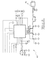
- FIGS 1 to 3 illustrate the circuitry used in further embodiment of the invention.
- FIG. 1 shows the core circuitry centred on the micro controller 20.
- the micro controller is preferably an 8 bit Atmel AT mega 128 micro controller.
- the micro controller can be programmed and can store data and is provided with a 256 megabyte flash memory 27.
- the USB port 22 is preferably a Silicon Technologies USB to UART data transfer CP 2101 and allows data to be down loaded to a personal computer for further analysis and storage and also allow the battery to be charged by way of the battery charger 31 which in turn is connected to the power supply 32.
- the microcontroller functions are actuated by the tactile switches 23 which allows the user to navigate through the device menu.
- the microcontroller displays outputs on the LCD display 35 and also provides a backlight display 36.
- the monitor includes a 2.4 GHz transmitter and receiver 40 so that data can be transmitted and received.
- the transmitter and receiver 40 see is preferably a GFSK transceiver nRF2401 sold by Nordic Semiconductor.
- the output power and frequency channels are programmable using a 3 wire serial interface.
- the GPS unit is an iTRAX 03 by Fastrax with 12 channels and an update rate below 5 Hz with a 1 Hz default rate.
- the sensor circuits shown in figure 3 are the core components of the real time clock 41 the three axis accelerometer 43 and the gyro sensor 45 which senses angular rate of change and needs its own power supply because it requires a different voltage to the other components.
- the preferred gyro is ADXRS300 which provides an output signal that is a voltage proportional to the angular rate about the axis normal to the top surface.
- a single external transistor may be used to lower the scale factor and an external capacitor is used to set the bandwidth.
- a display is mounted in a water proof enclosure in a visible location so that the athlete can view summary information such as speed, distance and heart rate.
- An easily accessible button on the display unit starts the data recording. As soon as the device is switched on recording begins. The coach may take the device after the event and load the data into a personal computer to view the data graphically or combine it synchronously with video footage.
- the device can be used to detect strokes and turns in swimming. Analysis of the accelerometer and gyro signals allows a coach to analyse the efficiency of strokes and turns.
- Figure 4 illustrates the gyro signals from a device mounted on a swimmer.
- the device may be attached to an athlete near the small of the back but may also be attached to the ankle adjacent the Achilles tendon or to the shoe or ski.
- An internal antenna may be used or alternatively an extension GPS aerial may be run from the device to the shoulders or other convenient point.
- a similar location is also suitable for swimming although mounting on the wrist or head is also possible.
- skiing and snowboarding the device may also be attached to the bike ski or snowboard.
- the device In cycling the device may be worn by the rider or mounted on the handlebars of the bike for easy visibility.
- the pedal cadence can be deduced from the accelerometer data but may be collected from a cadence sensor either wired to the monitor or sent by a wireless blue tooth arrangement.
- the RF module enables the real time data to be transmitted to the Coach's wireless enabled PC via a blue tooth connection. Alternatively the data may simply be uploaded after the event.
- the device can be adapted for a wide range of sports. Analysis of the signals from the 3 axes of the accelerometer allows coaches to derive information as detailed stride length and variations in the push from each leg of a runner. For long distance training session the data from a group of sensors can be presented as shown in figure 5 in which the first frame shows the 3 axes of the accelerometer; the second frame shows the velocity as derived with the assistance of the GPS sensor; the third frame shows the signals from the gyro sensor and the fourth frame contains the altimeter readings over the course.
- snow boarding loft time and speed can be derived from the data. This uses the accelerometer data to determine the lift off point and the return point to determine the air time.
- the gyro sensors can be used to analyse and evaluate the complexity of a trick during air time in snow boarding and skiing.
- the gyro sensors are also useful in swimming and football in analyzing an athletes movements such as a swimming stroke or a kick in foot ball.
- One algorithm according to this invention is designed to show air time and total angular movement during the "air". To detect the air it uses three parameters which are available at 100hz - forward/backward acceleration, up/down acceleration and ac3diff. The first two parameters are filtered through a 2 pass Butterworth filter with a 2.5hz cutoff. Each ac3diff value is the square root of the sum of the squares of the differences between adjacent triaxial accelerometer readings and is an indicator of activity. This algorithm first looks for the end of an "air” which is indicated by a large spike in ac3dif at landing. The spike must have 5 out of 6 ac3diff readings each at least 0.05 greater than the previous reading.
- the spike must also rise by at least 0.5 over the 6 readings and must be at least 0.7 secs after the end of the previous "air”.
- the algorithm looks back for the beginning of the "air” in the 0.3 to 2 seconds range. This is defined as a peak in upward acceleration with a steep approaching slope (10 of 20 points at least 0.03g above previous point). There must also be a similar steep drop in forward/backward acceleration.
- the integrated triaxial gyro data is used to calculate the angle the athlete moves through during the air time.
- the readings from a triaxial accelerometer, gyro sensor and GPS mounted on a bike are shown in figure 6 .
- Cadence and gear changes can be seen from the forward acceleration and velocity changes. This can be measured using the accelerometers and correcting with GPS.
- Altimeters can be included for bikes. By computing real forward acceleration the power can be measured. Thus the rider can see on the bike display distance, velocity, cadence and power.
- the device of this invention can separately analyse the various sections of the course and identify uphill, downhill, flat technical and non technical sections. This is also applicable to cross country skiing and running.
- the combination of gyro and accelerometer sensors enables hand balls and kicks to be detected.
- the algorithm looks for a peak in the pitch gyro (4 gyro readings increasing by 4 degrees per sec followed soon after by 4 decreasing by 3 deg/sec over a period of between 130 and 350ms.
- the first reading must be less than -90 deg/sec.
- the present invention provides a device that incorporates :
- the device In team sports, the device is typically worn on the upper back via a custom neoprene padded undergarment.
- the first step in the calculation is to determine the orientation of "up".
- the three orthogonal accelerometer sensors can measure instantaneous accelerations in space. This instantaneous acceleration can be expressed as a 3 dimensional vector. Although this instantaneous acceleration vector (Ai) is highly sensitive to movement, over a sufficient averaging period, a consistent "up" vector (Aavg) will emerge. Given that calculation of Aavg takes time, this system is insensitive to sudden changes in orientation.
- the orthogonal gyroscopes alleviate this problem. If we rotate Aavg by the pitch, roll, and yaw angles measured by the gyroscopes, the Aavg vector will remain responsive and valid.
- the gyroscopes may suffer from drift problems, but the magnitude of the drift is easily compensated for by the accelerometers.
- the gyroscopes are relied upon to adjust for snap turns and changes in orientation, and the accelerometers aggregate an average "up" vector that is insensitive to noise and can correct slow, long-term gyroscope drift that acts upon this average.
- the three orthogonal magnetometers also measure an instantaneous magnetic field vector (Mi).
- Mc instantaneous magnetic field vector
- gyroscope-measured rotations we can, in a similar manner to that of the accelerometers, calculate an average magnetic field vector (Mavg)
Abstract
Description
- This invention relates to an improved method and system for monitoring performance characteristics of athletes and in particular the particular movements which contribute to enhanced performance.
- Monitoring of athletes performance both in training and in competition is important in the development and implementation of new approaches aimed at improving sporting performance.
- The ability to measure and record athlete physiological information and positional information associated with athlete movement in real-time is critical in the process of athlete training and coaching. Blood oxygen, respiration, heart rates, velocity, acceleration/force, changes in direction, and position and many other factors are required in elite athlete training and coaching. The position, movement and force information plays an important role in effective analysis of the athlete performance, especially for rowers. For example, the stroke frequency, force and synchronisation of athletes are critical for the performance of the rowers in a competition. Currently the stroke information can only be measured in either dedicated sports laboratories or using simulated devices. Reliable analysis of the stroke rate and stroke distance in rowing has been a challenge for a long time due to the availability of the real scenario data, in particular a high precision of position, velocity and acceleration data. Existing technologies used for this purpose include theoretical studies, video-footage procedure, indoor tank procedure, computer modelling and ergometer studies. Much of the equipment is either too heavy, expensive, obtrusive or less reliable. Therefore, smart real-time monitoring during training and competition to help elite athletes to improve their performance and avoid injuries is critical for both athletes and coaches. Any methodology that would improve the situation would not only bring benefits to the rower practice, but also to many other sports related application including both team sports and individual athlete.
-
USA patents 4984986 and5099689 disclose measuring systems for off water rowing apparatus which measure the number of strokes or the force applied to the machine. -
USA patent 6308649 discloses a monitoring system for sail boat racing which provides feedback to the crew of such parameters as wind speed and direction boat speed, sail boat comfort parameters , sail shape, line tensions, rudder angle etc. - Some development of monitoring systems has occurred in non water sports.
-
USA 6148262 discloses a bike mounted sports computer including a GPS receiver to provide a mapping facility. -
W02004/039462 discloses a sensor for rowing which combines a GPS sensor with a three dimensional accelerometer. - In athletics the ability to monitor movement, acceleration and rhythm is useful in especially in track and field events. In team games such as football the ability to track and log the movements of players or log particular events or features of play, is useful to coaches.
- It is an object of this invention to provide a device for real time monitoring of athlete performance.
- To this end the present invention provides a data acquisition system for use in sporting events which incorporates
- a) At least one inertial sensor measuring angular acceleration in at least one dimension
- b) at least one accelerometer to derive acceleration and velocity data in 3 dimensions
- c) a microcontroller with a clock to measure the angular acceleration and accelerometer data
- d) a power supply
- e) an optional communication means for transmission of angular acceleration and accelerometer data from the microcontroller to a computer device
- f) said computer device and/or said micro controller being programmed to use the angular acceleration and accelerometer data to provide accurate output of parameters such as velocity, acceleration, changes of direction and distance travelled.
- This device will provide longitudinal data from the training and competition environment and provide both athlete physiological data and performance data related to the sport. The number of inertial sensors measuring angular acceleration will depend on the number of dimensions that information is required for and this will vary from sport to sport.
- A GPS receiver transmitter may be included in the device to derive location and speed parameters. In addition one or more magnetometers may be included in the device to derive direction of movement which can be combined with data from the GPS and accelerometer components. In some cases the magnetometers can be substituted for the angular acceleration sensors (gyros). In some circumstances the magnetometers are preferable to gyroscopes. For instance to construct an inertial navigation system, you require a gravity model to separate out acceleration due to gravity. This can be determined with the gyroscopes (the traditional approach), however the magnetometers may be combined with GPS for an inertial navigation system. Since the magnetometers provide a continuous 3d magnetic north vector, and the GPS gives latitude and longitude, it is possible to use the gyroscopes with GPS to construct a gravity model (remembering that a north vector in has a relationship with horizontal, depending on the latitude which is determined by the GPS. Magnetometers are usually less expensive than gyros, and the mathematics for the algorithm is much simpler enabling on the fly processing.
- Preferably physiological sensors are also attached to the athlete and integrated with the sensor system. Heart rate is the prime parameter to be measured and this may be sensed using electrical sensors or microphones. Respiratory rate is also important and may be measured by sensing the stretching of a chest band or using a microphone and signal recognition software. Another parameter is arterial oxygen saturation which may be measured non invasively by a sensor, placed on an earlobe or finger tip, using pulse oximetry employing an infra red absorption technique. Infra-red spectroscopy may be used for non invasive measurement of blood lactate concentrations.
- Preferably velocity is derived from the global position sensor or other wireless triangulation system and the accelerometer data is sampled to obtain movement characteristics of the sport being monitored. Preferably the accelerometer data is integrated to derive velocity related movement characteristics and drift is checked every second using the output from the global position sensor.
- Depending on the processing power of the microcontroller much of the data processing a display can be carried out on the sensor itself and an external computer may not be necessary. The device may also incorporate appropriate storage for the collected data. The data can be transmitted to other computers by wireless or cable transmission.
- This system provides a platform device which can be used for a wide range of sports simply by providing appropriate software to derive from the accelerometer and GPS data, the desired sport parameters such as stride frequency, velocity, stride length, vertical acceleration, time off the ground for long jumping and events such as aerial skiing or snowboarding. The angular acceleration sensor or gyro sensor measures angular change in up to 3 dimensions (pitch, yaw and roll) and is used to sense movements like strokes and turns in swimming or strides and loft time in running, or kicks in team sports such as football, in a similar fashion to accelerometers. Additionally the magnetometer sensors indicate direction of the movement.
- The system of this invention can be used in swimming to identify stroke type, turns, and with turns the number of laps and the stroke rate per lap as well as lap times. Careful analysis of each stroke can show the efficiency and power by comparing the acceleration and deceleration cycles and the effect of breathing cycles. In open water swimming the GPS can also be used to provide an indication of location, direction, and speed relative to the course.
- The system of this invention can be used in cycling to identify location, speed, power and heart rate. By adding a magnetometer to the unit on the cyclist pedal cadence can be sensed. Alternatively pedal cadence can be sensed by a unit on the bike and transferred to the unit on the cyclist using a radio frequency pickup unit. Pedal cadence can also be determined from the signals picked up from the accelerometer and the angular acceleration sensor.
- In skiing the unit can detect velocity, position, and heart rate but also the power imparted by each leg and the lateral acceleration and deceleration. In jumping the unit can detect loft time and speed.
- In team sports such as the various codes of football the movement of the player can be tracked. In addition to movement and position the direction and force of a kick, the impact force of a tackle or the energy expended in routines such as rucking, can be determined from the accelerometer and the angular acceleration sensor.
- Particular embodiments of the invention will be described.
-
Figure 1 the core circuit diagram for monitor mounted on an athlete; -
Figure 2 is the radio transceiver circuit for the monitor offigure 1 ; -
Figure 3 is the sensor circuits for the monitor offigure 1 ; -
Figure 4 displays the signal from a gyro sensor mounted on a swimmer; -
Figure 5 displays the readings of a number of sensors for a long distance run; -
Figure 6 are triaxial accelerometer and gyro readings from the device of this invention mounted on a bicycle; -
Figure 7 is a block diagram for second embodiment of the invention. - The device of this invention is a modification of the device described in Australian patent applications
2003277952 2006222732 - Recent developments in micro-electromechanical systems (MEMS) technology have opened new avenues for the use of high precision lightweight accelerometers and gyroscopes for new and challenging sports applications (eg. characterise rate and length of rowing stroke and stride). MEMS integrate both electrical and mechanical components on a single chip through extensive research into integrated circuit processing technologies. As MEMS accelerometers originated from monitoring vehicle safety and electronic stabilisation, they only provided very low accuracy measurements. However, as micromechanical devices are inherently smaller, lighter, and usually more precise than their macroscopic counterparts, more and more reliable sensors are becoming available. Accelerometers measure linear acceleration and gyroscopes measure angular acceleration (pitch, yaw and roll).
- In this invention accelerometers are used concurrently with gyroscopes to form an inertial or dead reckoning system. The deviation from a known starting point is determined by integration of acceleration in each axis over time. To minimize error the gyroscopes may be used to determine the orientation of the accelerometer and the integrator may be reset to known reference position upon each ground contact. Both gyroscopic and accelerometric transducers are combined to gather and transmit complete 3 dimensional information about an athletes motion.
- Inertial sensors errors include inertial system heading errors, gyro scale factor errors, accelerometer scale factor and bias errors and gyro bias errors. These drifts and biases inherent in the inertial sensors will cause a misalignment of the platform and errors in the sensed accelerations, which subsequently results in errors in computed velocities and positions.
- The advent of the advanced global navigation satellite systems (GNSS), GPS in particular, has revolutionized conventional precise positioning techniques. GPS has been made more amenable to a wide range of applications through the evolution of rapid static and kinematic methods, and now even more so with the advent of the On-The-Fly (OTF) technique and most recently network-based RTK techniques such as the Trimble virtual reference station system and
- Geo++ surface correction parameter method. Real-time Kinematic (RTK) or single epoch positioning allows for the determination of the integer ambiguities in real-time.
- The display device is a notebook computer or PDA programmed to present the data in a form that is useful to a coach or player.
- It is preferred that the device have data logging and IrDA transfer capabilities which makes data storage on the unit of slightly less importance. However storing data on the unit makes sense as the raw data can be streamed into the device and the greater processing power of the unit chip allows for flexible software and display development.
- The microprocessor is a Hitachi HD64F3672FP which stems from the H8/300H family. Its main features are:
- eight 32-bit registers OR sixteen 16-bit or sixteen 8-bit
- Serial communication Interface (SCI)
- 10-bit ADC (4 channels)
- 2 k bytes of RAM
- The accelerometer unit is powered from a 9Volt battery, which is regulated down to 5volts internally. The dimensions of the accelerometer unit are 25mm x 30mm x 9mm (smaller that the average matchbox). The cover needs to be water proof but importantly the on/off buttons and start/stop buttons etc must be able to be accessed even when the athletes are wearing gloves.
- All the chips that have been selected are amongst the smallest available in their range, the Hitachi HD64F3672FP measures on 12mm x 12mm, this incorporates a 64 pin architecture and the ADXL202 measuring only 5mm x 5mm.
- A GPS unit may be integrated with the data logger system. This could comprise two units, basic unit plus a second unit for GPS. The units would share the same serial line and communicate using a network protocol. Alternatively the GPS unit could be connected to the basic unit and additional firmware code added to receive and retransmit data.
- Inertial navigation systems (INS) may be used to cover the information gaps of the GPS outages. When the INS approach is used in rowing, the required sensors need to be small, lightweight, unobtrusive and inexpensive. These requirements can be met when the sensors are manufactured with MEMS technology. However, due to inherent biases and drift errors of accelerometers and gyroscopes, the accuracy of the current state-of-the-art MEMS sensors must be accounted for in high precision tracking. The basic procedure in INS positioning systems is to process the inertial sensor data. The double integration of acceleration measurements, cannot be applied due to the lower accuracy of MEMS sensors. This is because in the double integration, errors accumulate quickly, which soon result in velocity errors comparable to typical rowing speeds. However, the advantages of the INS system include its low cost and high output rate of the movement information.
- The high precision GPS system can provide high precision velocity and acceleration information (acceleration is the first derivative of velocity and second derivative of displacement). However the GPS system is normally bulky, expensive and provides a low output rate and high power consumption. To solve these problems, an integrated system takes advantage of both low-cost
- GPS and MEMS sensors to provide high performance capabilities. MEMS sensors are used to provide precise, high rate (say 200Hz), low cost, low volume, low power, rugged, and reliable geo-positioning while low-cost GPS may be used for high frequency system calibration (say 5-20Hz) a lower frequency (1 Hz) is preferred for calibrating the inertial sensors to conserve battery power. It combines measurements from a GPS OEM board and subsequently GPS chip with inertial measurement units from a combination of three MEMS gyroscopes and accelerometers (say Analog Devices). No minimum frequency is necessary but a 1 Hz GPS receiver is practical and ideally a 2-5 Hz system is preferred. With a 1 Hz receiver accurate velocity and distance measurements can be obtained but sampling the accelerometer data is needed to obtain stroke rate and intra-stroke characteristics. The accelerometer data could be integrated to get intra-stroke velocity but drift would need to be checked every second using the output from the GPS receiver.
- A carrier smoothing procedure may be used to improve the accuracy of the low-cost GPS pseudo range measurements. Carrier phase smoothing is a process that the absolute but noisy pseudo range measurements are combined with the accurate but ambiguous carrier phase measurements to obtain a good solution without the noise inherent in pseudo range tracking through a weighted averaging process. A Kalman filtering system will be designed to integrate the two system measurements.
- Relative motion of the athlete may be measured using three dimensional accelerometer at say 100hHz and position and velocity using GPS at say 10Hz.
- The device supplies timing information with the measured signals using an internal crystal corrected clock and a GPS derived 1 Hz pulse. The timing is accurate to 0.1 sec per hour. An internal heart rate monitor pickup receives pulses from a coded polar heart rate monitor/transmitter and stores these with a resolution of 1 beat a minute within a range of 0 to 250 beats/minute updated at 1 Hz. The device is powered by a battery sealed into the unit and is rechargeable via an RS232 port. Recording battery life is 6 hours and 1 month in sleep mode. The single universal port allows recharging, connecting an RF module, connecting an external GPS antenna, connecting the external heart rate receiver and to connect a serial cable to send data to the hand held computer device. The device can be fitted into a flexible package of a size approximately 100mmx70mmx50mm and weighs less than 250g and is buoyant and water resistant. The package is coloured to reduce heating from incident sunlight.
-
Figures 1 to 3 illustrate the circuitry used in further embodiment of the invention. -
Figure 1 shows the core circuitry centred on themicro controller 20. The micro controller is preferably an 8 bit Atmel AT mega 128 micro controller. The micro controller can be programmed and can store data and is provided with a 256 megabyte flash memory 27. TheUSB port 22 is preferably a Silicon Technologies USB to UART data transfer CP 2101 and allows data to be down loaded to a personal computer for further analysis and storage and also allow the battery to be charged by way of thebattery charger 31 which in turn is connected to thepower supply 32. The microcontroller functions are actuated by thetactile switches 23 which allows the user to navigate through the device menu. The microcontroller displays outputs on theLCD display 35 and also provides abacklight display 36. As shown infig 2 the monitor includes a 2.4 GHz transmitter andreceiver 40 so that data can be transmitted and received. The transmitter andreceiver 40 see is preferably a GFSK transceiver nRF2401 sold by Nordic Semiconductor. The output power and frequency channels are programmable using a 3 wire serial interface. The GPS unit is an iTRAX 03 by Fastrax with 12 channels and an update rate below 5 Hz with a 1 Hz default rate. - The sensor circuits shown in
figure 3 are the core components of thereal time clock 41 the threeaxis accelerometer 43 and thegyro sensor 45 which senses angular rate of change and needs its own power supply because it requires a different voltage to the other components. The preferred gyro is ADXRS300 which provides an output signal that is a voltage proportional to the angular rate about the axis normal to the top surface. A single external transistor may be used to lower the scale factor and an external capacitor is used to set the bandwidth. - A display is mounted in a water proof enclosure in a visible location so that the athlete can view summary information such as speed, distance and heart rate. An easily accessible button on the display unit starts the data recording. As soon as the device is switched on recording begins. The coach may take the device after the event and load the data into a personal computer to view the data graphically or combine it synchronously with video footage.
- The device can be used to detect strokes and turns in swimming. Analysis of the accelerometer and gyro signals allows a coach to analyse the efficiency of strokes and turns.
Figure 4 illustrates the gyro signals from a device mounted on a swimmer. - For athletics or skiing the device may be attached to an athlete near the small of the back but may also be attached to the ankle adjacent the Achilles tendon or to the shoe or ski. An internal antenna may be used or alternatively an extension GPS aerial may be run from the device to the shoulders or other convenient point. A similar location is also suitable for swimming although mounting on the wrist or head is also possible. For cycling , skiing and snowboarding the device may also be attached to the bike ski or snowboard.
- In cycling the device may be worn by the rider or mounted on the handlebars of the bike for easy visibility. The pedal cadence can be deduced from the accelerometer data but may be collected from a cadence sensor either wired to the monitor or sent by a wireless blue tooth arrangement.
- The RF module enables the real time data to be transmitted to the Coach's wireless enabled PC via a blue tooth connection. Alternatively the data may simply be uploaded after the event.
- The device can be adapted for a wide range of sports. Analysis of the signals from the 3 axes of the accelerometer allows coaches to derive information as detailed stride length and variations in the push from each leg of a runner. For long distance training session the data from a group of sensors can be presented as shown in
figure 5 in which the first frame shows the 3 axes of the accelerometer; the second frame shows the velocity as derived with the assistance of the GPS sensor; the third frame shows the signals from the gyro sensor and the fourth frame contains the altimeter readings over the course. - In skiing can show the power derived from each leg thrust or pole thrust.
- In snow boarding loft time and speed can be derived from the data. This uses the accelerometer data to determine the lift off point and the return point to determine the air time. The gyro sensors can be used to analyse and evaluate the complexity of a trick during air time in snow boarding and skiing. The gyro sensors are also useful in swimming and football in analyzing an athletes movements such as a swimming stroke or a kick in foot ball.
- One algorithm according to this invention is designed to show air time and total angular movement during the "air". To detect the air it uses three parameters which are available at 100hz - forward/backward acceleration, up/down acceleration and ac3diff. The first two parameters are filtered through a 2 pass Butterworth filter with a 2.5hz cutoff. Each ac3diff value is the square root of the sum of the squares of the differences between adjacent triaxial accelerometer readings and is an indicator of activity. This algorithm first looks for the end of an "air" which is indicated by a large spike in ac3dif at landing. The spike must have 5 out of 6 ac3diff readings each at least 0.05 greater than the previous reading. The spike must also rise by at least 0.5 over the 6 readings and must be at least 0.7 secs after the end of the previous "air". The algorithm then looks back for the beginning of the "air" in the 0.3 to 2 seconds range. This is defined as a peak in upward acceleration with a steep approaching slope (10 of 20 points at least 0.03g above previous point). There must also be a similar steep drop in forward/backward acceleration.
- Once the bounds of the air time are established the integrated triaxial gyro data is used to calculate the angle the athlete moves through during the air time.
- This is a measure of the complexity of the trick.
- The readings from a triaxial accelerometer, gyro sensor and GPS mounted on a bike are shown in
figure 6 . Cadence and gear changes can be seen from the forward acceleration and velocity changes. This can be measured using the accelerometers and correcting with GPS. Altimeters can be included for bikes. By computing real forward acceleration the power can be measured. Thus the rider can see on the bike display distance, velocity, cadence and power. - In mountain biking, the device of this invention can separately analyse the various sections of the course and identify uphill, downhill, flat technical and non technical sections. This is also applicable to cross country skiing and running.
- In football codes the combination of gyro and accelerometer sensors enables hand balls and kicks to be detected. The algorithm looks for a peak in the pitch gyro (4 gyro readings increasing by 4 degrees per sec followed soon after by 4 decreasing by 3 deg/sec over a period of between 130 and 350ms. The first reading must be less than -90 deg/sec.
- In the further embodiment as illustrated in the block diagram of
figure 7 the present invention provides a device that incorporates : - 3 axis Kionix accelerometers (KXM52-1050) which are low power and low noise in a small footprint
- 3 gyroscopes from Analogue devices (ADXRS300) aligned orthogonally to measure rotation in 3 directions
- 2 x 2D magnetometers from Hitachi (HM55B), which combine to give a 3 dimensional electronic compass
- A fastrax itrax GPS chip which can be configured to run at up to 5 Hz
- A nanotron nanolock wireless chip enabling wireless communication at 2.4GHz with a chirp spread spectrum protocol. Custom written TDMA software enables up to 128 minimaxX devices to broadcast data to a remote coach in real time.
- An ARM based micro processor from Atmel (AT91 SAM7X256)
- 600mAhr Lithium Ion rechargeable battery
- 6 layer PCB
- A high resolution color LCD
- In an impact resistant injection moulded plastic case.
- A temperature compensated oscillator for high accuracy timing
- 256MB of trans flash memory
- In team sports, the device is typically worn on the upper back via a custom neoprene padded undergarment.
- The addition of the gyroscopes and magnetometers to the package enable a huge number of possibilities in feature extraction for sports.
- For instance leading research in strength and conditioning training for soccer is discovering that a large percentage of game play involves running sideways or backwards. Measuring this routinely enables coaches to train athletes for this activity. The combination of magnetometers and GPS provides the orientation of the unit and the heading of the player, enabling users to resolve the direction of movement, and then break this activity into velocity bands in different directions. Specific training activity can target fitness in these areas.
-
- Facing Algorithm
- The facing calculations take advantage of the onboard accelerometers, magnetometers, and gyroscopes in the device.
- The first step in the calculation is to determine the orientation of "up". The three orthogonal accelerometer sensors can measure instantaneous accelerations in space. This instantaneous acceleration can be expressed as a 3 dimensional vector. Although this instantaneous acceleration vector (Ai) is highly sensitive to movement, over a sufficient averaging period, a consistent "up" vector (Aavg) will emerge. Given that calculation of Aavg takes time, this system is insensitive to sudden changes in orientation. The orthogonal gyroscopes alleviate this problem. If we rotate Aavg by the pitch, roll, and yaw angles measured by the gyroscopes, the Aavg vector will remain responsive and valid.
- The gyroscopes may suffer from drift problems, but the magnitude of the drift is easily compensated for by the accelerometers.
- In other words, the gyroscopes are relied upon to adjust for snap turns and changes in orientation, and the accelerometers aggregate an average "up" vector that is insensitive to noise and can correct slow, long-term gyroscope drift that acts upon this average.
- The three orthogonal magnetometers also measure an instantaneous magnetic field vector (Mi). By use of averaging and applying gyroscope-measured rotations, we can, in a similar manner to that of the accelerometers, calculate an average magnetic field vector (Mavg)
- As the Earth's magnetic field is not tangent to the Earth's surface at all points, we need to extract the (Earth relative) horizontal components of the field.
- At this point the device has calculated:
- Aavg (average device-relative up vector)
- Mavg (average device-relative north vector)
A North-In-Plane vector is calculated by subtracting from Mavg the vector projection of Mavg on Aavg. In other words the horizontal plane is defined as being orthogonal to Aavg (which is Up), and the vector projection of Mavg onto this plane is taken.
The North-In-Plane vector now holds a device-relative indication of north, constrained to the horizon (as given by Aavg, or the "up" vector)
This is used to define a new vector - a fixed, device-relative indication of "forward". This "forward" vector is not calculated, it is constant and defined.
This vector is projected onto the horizon plane implied by Aavg, to generate a vector called Forward-In-Plane.
At this point, the device has calculated:
North-In-Plane - a device relative vector indicating the direction of north, constrained to the horizon.
Forward-In-Plane - a device relative vector indicating the direction of forward, constrained to the horizon.
Finally, facing is defined as the angle that must be swept by rotating clockwise (as seen from above) from the North-In-Plane vector to the Forward-In-Plane vector. By understanding the facing direction f the player backward movement, which is an important skill in sports such as soccer and basketball , can be identified and examined.
In another example, quantification of kicking frequency and intensity is important in monitoring training load and preventing injury. Too many long kicks leads to a higher incidence of osteitis pubis. On the other hand, too few kicking drills leads to poor accuracy and performance. The kicking action in soccer, AFL and other sports results in a distinctive pitching of the back, accompanied by a discontinuity in stride rate. The gyroscopes measure the pitch and the accelerometers the stride, enabling this feature to be automatically extracted and analysed. The magnetometers give further information in the direction of the kick. The GPS signal indicates the position on the field when the kick occurs.
A further feature in elite sports which is of particular interest to strength and conditioning coaches and to rehabilitation, is the intensity and frequency of sharp high velocity turns (ie a player is running hard and has a sharp change in direction). In this case the device, according to this embodiment, can measure the velocity via GPS, and the angular acceleration of the turn via the yaw gyroscope. This enables counting and categorization of the effort, so that training regimes can be made to reflect game needs, and rehabilitating players can have there training loads monitored so that this intense activity is controlled to minimize risk of further injury or interruption to recovery. This is particularly relevant to the current practice of small game training (playing football matches on scaled down fields), which is designed to intensify activity, but results in more sharp turns and potentially more associated injuries.
In the case of rugby, the combination of sensors is used to measure the impact force of a tackle (via accelerometers), the direction of impact (via resolving accelerometer forces), the direction a player was running (via magnetometer), the tackle time (defined as the time from initial impact to the time the player gets off the ground) is determined via a combination of magnetomers and accelerometers providing the time the player is not in a vertical orientation.
The example below shows a series of 6 tackles in a rugby league game. The data is filtered to eliminate high frequencies, and then each tackle is quantified.
In field hockey, the gyroscopes show particular patterns from the sweeping action of striking the ball, the accelerometers show impact with the ball from the jarring motion translated into the body, and the magnetometers show the direction the player is facing, enabling quanitification of long passes.
In general, the combination of all the sensors provides a large number of channels recording the players movement. For any particular feature of play (a kick, tackle, scrum, throw in, etc.) all channels can be examined for a characteristic pattern. Although many times the pattern in one channel will not be completely unique for the activity. Experience has shown that the particular array of sensors in this embodiment generally shows a unique combination of patterns across all sensors. This opens up the possibility of quantifying and analysis all sorts of sports (or general human) activities for use in training, injury prevention, rehabilitation and security monitoring.
A further benefit of this combination of sensors is the ability to combine the outputs to form an inertial navigation system. GPS typically records position, velocity etc. once per second (although in this embodiment the GPS runs up to 5 times per second). In fast moving sports, this is inadequate for accurately monitoring athlete activity because important events happen in split seconds.
Combining the inertial navigation system of the accelerometers with the GPS enables detailed time domain information. For instant velocity at 100Hz can be derived. The software used in this embodiment allows this data to be synchronized to video footage. Highly detailed biomechanical information can then be analysed with respect to video footage for breaking down technique and performance. The inertial navigation system by itself is not able to provide this information because of the drift and offset in typically real sensors. This leads to accumulation of errors in the data. Furthermore a purely inertial based navigation system does not have an absolute reference point - which can be provided by GPS.
Those skilled in the art will realize that the invention may be implemented in a variety of embodiments depending on the water craft used and the number of personnel in the water craft. A variety of sensors may also be used to gather data applicable to the event and the water craft. It will also be appreciated that the logger unit is small and adaptable enough to be fitted to any athlete or sporting equipment where accelerometer data provides useful performance information for coaches and athletes. These include athletics, swimming, team sports such as various football codes, cycling and skiing.
Claims (10)
- A data acquisition system for use in sporting events which incorporatesa. at least one inertial sensor measuring angular acceleration in at least one dimensionb. at least one accelerometer to derive acceleration and velocity data in 3 dimensionsc. a microcontroller with a clock to measure the angular acceleration and accelerometer datad. a power supplye optional communication means for transmission of angular acceleration and accelerometer data from the microcontroller to a computer devicef. said computer device and/or said micro controller being programmed to use the angular acceleration and accelerometer data to provide accurate output of parameters such as velocity, acceleration, changes of direction and distance travelled.
- A data acquisition system as claimed in claim 1 which also includes a GPS sensor and velocity is derived from the global position sensor and the accelerometer and angular change data is sampled to obtain movement characteristics of the sport being monitored.
- A data acquisition system as claimed in claim 2 which also includes a magnetometer which combined with GPS data can provide directional data.
- A data acquisition system as claimed in claim 1 which also includes a physiological sensor.
- A data acquisition system as claimed in claim 4 in the physiological sensor is a heart rate monitor.
- A data acquisition system as claimed in claim 1 for a cyclist which also includes a pedal cadence sensor.
- A data acquisition system for use in sporting events which incorporatesa) at least one accelerometer to derive acceleration and velocity data in 3 dimensionsb) at least one magnetometer sensing the direction of magnetic northc) a Global Positioning Sensor (GPS)d) a microcontroller with a clock to measure the magnetometer, GPS
and accelerometer datae) a power supplyf) optional communication means for transmission of magnetometer,
GPS and accelerometer data from the microcontroller to a computer deviceg) said computer device and/or said micro controller being programmed to use the magnetometer, GPS and accelerometer data to provide accurate output of parameters such as velocity, acceleration, changes of direction and distance travelled. - A data acquisition system as claimed in claim 7 which also includes at least one inertial sensor measuring angular acceleration in at least one dimension
- A data acquisition system as claimed in claim 7 which also includes a physiological sensor.
- A data acquisition system as claimed in claim 9 in the physiological sensor is a heart rate monitor.
Priority Applications (1)
| Application Number | Priority Date | Filing Date | Title |
|---|---|---|---|
| EP21212341.8A EP4035748A1 (en) | 2007-05-18 | 2008-05-16 | Improved sports sensor |
Applications Claiming Priority (1)
| Application Number | Priority Date | Filing Date | Title |
|---|---|---|---|
| AU2007902652A AU2007902652A0 (en) | 2007-05-18 | Improved Sports Sensor |
Related Child Applications (1)
| Application Number | Title | Priority Date | Filing Date |
|---|---|---|---|
| EP21212341.8A Division EP4035748A1 (en) | 2007-05-18 | 2008-05-16 | Improved sports sensor |
Publications (1)
| Publication Number | Publication Date |
|---|---|
| EP1992389A1 true EP1992389A1 (en) | 2008-11-19 |
Family
ID=39672731
Family Applications (2)
| Application Number | Title | Priority Date | Filing Date |
|---|---|---|---|
| EP21212341.8A Pending EP4035748A1 (en) | 2007-05-18 | 2008-05-16 | Improved sports sensor |
| EP08156407A Ceased EP1992389A1 (en) | 2007-05-18 | 2008-05-16 | Improved sports sensor |
Family Applications Before (1)
| Application Number | Title | Priority Date | Filing Date |
|---|---|---|---|
| EP21212341.8A Pending EP4035748A1 (en) | 2007-05-18 | 2008-05-16 | Improved sports sensor |
Country Status (3)
| Country | Link |
|---|---|
| US (1) | US8036826B2 (en) |
| EP (2) | EP4035748A1 (en) |
| AU (1) | AU2008202170B2 (en) |
Cited By (21)
| Publication number | Priority date | Publication date | Assignee | Title |
|---|---|---|---|---|
| GB2465824A (en) * | 2008-12-03 | 2010-06-09 | James Christopher Irlam | Motion analysis device for sports |
| WO2011157607A1 (en) | 2010-06-16 | 2011-12-22 | Myotest Sa | Integrated portable device and method implementing an accelerometer for analysing biomechanical parameters of a stride |
| CN102435165A (en) * | 2011-09-07 | 2012-05-02 | 石家庄铁道大学 | CNSS (COMPASS navigation satellite system)-based long-term ground facility deformation monitoring system and CNSS-based long-term ground facility deformation monitoring method |
| FR2997184A1 (en) * | 2012-10-23 | 2014-04-25 | Julien Beaumier | Mileage odometer for installation on handlebar for measuring kilometers travelled by bicycle, has measuring systems inserted into casing, and connected to microprocessor that stores information about rotation of wheel of bicycle |
| CN104459406A (en) * | 2014-12-12 | 2015-03-25 | 深圳供电局有限公司 | State monitoring terminal processing device |
| WO2015074140A1 (en) * | 2013-11-21 | 2015-05-28 | Vladimir Savchenko | Method and apparatus to measure motion characteristics for bicycles and any vehicles on wheels |
| CN104713554A (en) * | 2015-02-01 | 2015-06-17 | 北京工业大学 | Indoor positioning method based on MEMS insert device and android smart mobile phone fusion |
| WO2015128226A1 (en) * | 2014-02-26 | 2015-09-03 | Koninklijke Philips N.V. | Device for measuring a cycling cadence |
| CN105403229A (en) * | 2015-12-17 | 2016-03-16 | 杭州米为科技有限公司 | Novel stopwatch |
| WO2016071726A1 (en) * | 2014-11-07 | 2016-05-12 | Umm Al-Qura University | System and method for coach decision support |
| EP3139349A1 (en) * | 2015-09-03 | 2017-03-08 | Swiss Timing Ltd. | Method and system for measuring or predicting a hurdle race time |
| ITUB20155574A1 (en) * | 2015-11-13 | 2017-05-13 | Zero Sa | PROTECTION DEVICE FOR WORKING ACTIVITIES? SPORTY |
| US9724040B2 (en) | 2012-10-09 | 2017-08-08 | Laurent Fort | Garment integrating a system for collecting physiological data |
| WO2017133730A1 (en) * | 2016-02-05 | 2017-08-10 | Benjamin Bruder | Method for acquiring biomechanical and biometric data, and relevant device |
| WO2017160155A1 (en) * | 2016-03-18 | 2017-09-21 | Zxy Sport Tracking As | System and method for capturing moving behaviours of a horse |
| WO2018132012A1 (en) | 2017-01-13 | 2018-07-19 | Team Absolute B.V. | Wearable wireless electronic sports device |
| US10108854B2 (en) | 2015-05-18 | 2018-10-23 | Sstatzz Oy | Method and system for automatic identification of player |
| CN109186603A (en) * | 2018-08-16 | 2019-01-11 | 浙江树人学院 | 3-D positioning method in a kind of fireman room based on multisensor |
| US10486049B2 (en) | 2013-03-15 | 2019-11-26 | Amer Sports Digital Services Oy | Device and method for monitoring swimming performance |
| CN111238483A (en) * | 2020-02-12 | 2020-06-05 | 上海海事大学 | Low-power-consumption terrain auxiliary navigation system and method based on SIR particle filtering method |
| WO2022042962A1 (en) * | 2020-08-28 | 2022-03-03 | Robert Bosch Gmbh | A controller and a method to determine a swim stroke |
Families Citing this family (129)
| Publication number | Priority date | Publication date | Assignee | Title |
|---|---|---|---|---|
| WO2008008230A2 (en) * | 2006-07-10 | 2008-01-17 | Memsic, Inc. | A system for sensing yaw rate using a magnetic field sensor and portable electronic devices using the same |
| WO2008120149A1 (en) * | 2007-04-02 | 2008-10-09 | Nxp B.V. | Low cost electronic compass with 2d magnetometer |
| US8120498B2 (en) * | 2007-09-24 | 2012-02-21 | Intel-Ge Care Innovations Llc | Capturing body movement related to a fixed coordinate system |
| EP2215494A1 (en) * | 2007-11-30 | 2010-08-11 | Nokia Corporation | Controlling operation of a positioning module |
| US8088044B2 (en) | 2008-03-03 | 2012-01-03 | Nike, Inc. | Interactive athletic equipment system |
| US9301712B2 (en) * | 2008-07-29 | 2016-04-05 | Portland State University | Method and apparatus for continuous measurement of motor symptoms in parkinson's disease and essential tremor with wearable sensors |
| US20100076348A1 (en) * | 2008-09-23 | 2010-03-25 | Apdm, Inc | Complete integrated system for continuous monitoring and analysis of movement disorders |
| US8628453B2 (en) | 2008-12-05 | 2014-01-14 | Nike, Inc. | Athletic performance monitoring systems and methods in a team sports environment |
| US20100184564A1 (en) | 2008-12-05 | 2010-07-22 | Nike, Inc. | Athletic Performance Monitoring Systems and Methods in a Team Sports Environment |
| US8231506B2 (en) | 2008-12-05 | 2012-07-31 | Nike, Inc. | Athletic performance monitoring systems and methods in a team sports environment |
| US8647287B2 (en) | 2008-12-07 | 2014-02-11 | Andrew Greenberg | Wireless synchronized movement monitoring apparatus and system |
| US8920345B2 (en) * | 2008-12-07 | 2014-12-30 | Apdm, Inc. | System and apparatus for continuous monitoring of movement disorders |
| US8988240B2 (en) * | 2009-01-15 | 2015-03-24 | AvidaSports, LLC | Performance metrics |
| US20100250179A1 (en) * | 2009-03-27 | 2010-09-30 | Thomas Mariano | Method and apparatus for measuring and estimating subject motion in variable signal reception environments |
| US20100268551A1 (en) * | 2009-04-20 | 2010-10-21 | Apdm, Inc | System for data management, analysis, and collaboration of movement disorder data |
| US8475371B2 (en) * | 2009-09-01 | 2013-07-02 | Adidas Ag | Physiological monitoring garment |
| US8437951B2 (en) * | 2009-09-14 | 2013-05-07 | Research In Motion Limited | Methods, device and systems for determining route metrics using stored route information |
| US10668333B2 (en) | 2009-11-19 | 2020-06-02 | Wilson Sporting Goods Co. | Football sensing |
| US10751579B2 (en) | 2009-11-19 | 2020-08-25 | Wilson Sporting Goods Co. | Football sensing |
| US9636550B2 (en) | 2009-11-19 | 2017-05-02 | Wilson Sporting Goods Co. | Football sensing |
| US10821329B2 (en) | 2009-11-19 | 2020-11-03 | Wilson Sporting Goods Co. | Football sensing |
| US20120239290A1 (en) * | 2009-12-02 | 2012-09-20 | Pioneer Corporation | Information processing apparatus, information processing system, information processing method and bicycle map |
| FR2953284A1 (en) * | 2009-12-02 | 2011-06-03 | Movea Sa | SYSTEM AND METHOD FOR DRIVER ASSISTANCE OF BIOMECHANIC DRIVE VEHICLE COMPRISING AT LEAST ONE WHEEL |
| EP2521485B1 (en) * | 2010-01-08 | 2024-03-20 | Dayton Technologies Limited | Physiological signal collection apparatus and performance monitoring apparatus incorporating same |
| US9354447B2 (en) * | 2010-01-18 | 2016-05-31 | Intel Corporation | Head mounted information systems and related methods |
| JP4877395B2 (en) * | 2010-01-19 | 2012-02-15 | セイコーエプソン株式会社 | Stride estimation method and stride estimation apparatus |
| US20110213278A1 (en) * | 2010-02-26 | 2011-09-01 | Apdm, Inc. | Movement monitoring system and apparatus for objective assessment of movement disorders |
| US9247212B2 (en) | 2010-08-26 | 2016-01-26 | Blast Motion Inc. | Intelligent motion capture element |
| US8827824B2 (en) | 2010-08-26 | 2014-09-09 | Blast Motion, Inc. | Broadcasting system for broadcasting images with augmented motion data |
| US9406336B2 (en) | 2010-08-26 | 2016-08-02 | Blast Motion Inc. | Multi-sensor event detection system |
| US9261526B2 (en) | 2010-08-26 | 2016-02-16 | Blast Motion Inc. | Fitting system for sporting equipment |
| US9418705B2 (en) | 2010-08-26 | 2016-08-16 | Blast Motion Inc. | Sensor and media event detection system |
| US8944928B2 (en) | 2010-08-26 | 2015-02-03 | Blast Motion Inc. | Virtual reality system for viewing current and previously stored or calculated motion data |
| US9643049B2 (en) | 2010-08-26 | 2017-05-09 | Blast Motion Inc. | Shatter proof enclosure and mount for a motion capture element |
| US8994826B2 (en) | 2010-08-26 | 2015-03-31 | Blast Motion Inc. | Portable wireless mobile device motion capture and analysis system and method |
| US9619891B2 (en) | 2010-08-26 | 2017-04-11 | Blast Motion Inc. | Event analysis and tagging system |
| US8702516B2 (en) | 2010-08-26 | 2014-04-22 | Blast Motion Inc. | Motion event recognition system and method |
| US9604142B2 (en) | 2010-08-26 | 2017-03-28 | Blast Motion Inc. | Portable wireless mobile device motion capture data mining system and method |
| US9746354B2 (en) | 2010-08-26 | 2017-08-29 | Blast Motion Inc. | Elastomer encased motion sensor package |
| US9940508B2 (en) | 2010-08-26 | 2018-04-10 | Blast Motion Inc. | Event detection, confirmation and publication system that integrates sensor data and social media |
| US9235765B2 (en) | 2010-08-26 | 2016-01-12 | Blast Motion Inc. | Video and motion event integration system |
| US9033810B2 (en) | 2010-08-26 | 2015-05-19 | Blast Motion Inc. | Motion capture element mount |
| US10254139B2 (en) | 2010-08-26 | 2019-04-09 | Blast Motion Inc. | Method of coupling a motion sensor to a piece of equipment |
| US9626554B2 (en) | 2010-08-26 | 2017-04-18 | Blast Motion Inc. | Motion capture system that combines sensors with different measurement ranges |
| US9320957B2 (en) | 2010-08-26 | 2016-04-26 | Blast Motion Inc. | Wireless and visual hybrid motion capture system |
| US8903521B2 (en) | 2010-08-26 | 2014-12-02 | Blast Motion Inc. | Motion capture element |
| US9028337B2 (en) | 2010-08-26 | 2015-05-12 | Blast Motion Inc. | Motion capture element mount |
| US9646209B2 (en) | 2010-08-26 | 2017-05-09 | Blast Motion Inc. | Sensor and media event detection and tagging system |
| US8905855B2 (en) | 2010-08-26 | 2014-12-09 | Blast Motion Inc. | System and method for utilizing motion capture data |
| US9076041B2 (en) | 2010-08-26 | 2015-07-07 | Blast Motion Inc. | Motion event recognition and video synchronization system and method |
| US8941723B2 (en) | 2010-08-26 | 2015-01-27 | Blast Motion Inc. | Portable wireless mobile device motion capture and analysis system and method |
| US9607652B2 (en) | 2010-08-26 | 2017-03-28 | Blast Motion Inc. | Multi-sensor event detection and tagging system |
| US9039527B2 (en) | 2010-08-26 | 2015-05-26 | Blast Motion Inc. | Broadcasting method for broadcasting images with augmented motion data |
| US9396385B2 (en) | 2010-08-26 | 2016-07-19 | Blast Motion Inc. | Integrated sensor and video motion analysis method |
| US8613676B2 (en) | 2010-08-26 | 2013-12-24 | Blast Motion, Inc. | Handle integrated motion capture element mount |
| US9622361B2 (en) | 2010-08-26 | 2017-04-11 | Blast Motion Inc. | Enclosure and mount for motion capture element |
| US9401178B2 (en) | 2010-08-26 | 2016-07-26 | Blast Motion Inc. | Event analysis system |
| CN113270185A (en) | 2010-11-10 | 2021-08-17 | 耐克创新有限合伙公司 | System and method for time-based athletic activity measurement and display |
| CA2827501A1 (en) | 2011-02-17 | 2012-08-23 | Nike International Ltd. | Location mapping |
| US8573982B1 (en) | 2011-03-18 | 2013-11-05 | Thomas C. Chuang | Athletic performance and technique monitoring |
| CN102221369B (en) * | 2011-04-29 | 2012-10-10 | 闫文闻 | Gesture recognizing method and device of ball game and gesture auxiliary device |
| US8758172B2 (en) | 2011-05-18 | 2014-06-24 | Thomas Creguer | Sports training system |
| US9795177B1 (en) | 2011-10-06 | 2017-10-24 | Steven Douglas Weaver | Head-mounted impact sensing and warning device |
| US8913134B2 (en) | 2012-01-17 | 2014-12-16 | Blast Motion Inc. | Initializing an inertial sensor using soft constraints and penalty functions |
| US10338091B2 (en) | 2012-02-08 | 2019-07-02 | Ashton Wackym | Concussion detection and communication system |
| US10922383B2 (en) * | 2012-04-13 | 2021-02-16 | Adidas Ag | Athletic activity monitoring methods and systems |
| DE102012009195A1 (en) * | 2012-05-10 | 2013-11-14 | Alexander Hüttenbrink | Device arrangement and method for the dynamic positioning of one or more persons |
| US9486693B2 (en) | 2012-08-31 | 2016-11-08 | Catapult Group International Pty Ltd. | Sports data collection and presentation |
| US9613239B2 (en) | 2012-09-27 | 2017-04-04 | Chep Technology Pty Limited | Pattern recognition based motion detection for asset tracking system |
| US20140111352A1 (en) * | 2012-10-22 | 2014-04-24 | Madison J. Doherty | System and apparatus for graphical athletic performance analysis |
| US9060682B2 (en) | 2012-10-25 | 2015-06-23 | Alpinereplay, Inc. | Distributed systems and methods to measure and process sport motions |
| US10159884B2 (en) | 2012-11-09 | 2018-12-25 | Wilson Sporting Goods Co. | Basketball make-miss shot sensing |
| US9283457B2 (en) | 2012-11-09 | 2016-03-15 | Wilson Sporting Goods Co. | Sport performance system with ball sensing |
| US9844704B2 (en) | 2012-11-09 | 2017-12-19 | Wilson Sporting Goods Co. | Basketball sensing apparatus |
| US9724570B2 (en) | 2012-11-09 | 2017-08-08 | Wilson Sporting Goods Co. | Ball lighting |
| US9656140B2 (en) | 2012-11-09 | 2017-05-23 | Wilson Sporting Goods Co. | Sport performance system with ball sensing |
| US9623311B2 (en) | 2012-11-09 | 2017-04-18 | Wilson Sporting Goods Co. | Basketball sensing apparatus |
| US9656142B2 (en) | 2012-11-09 | 2017-05-23 | Wilson Sporting Goods Co. | Basketball shot determination system |
| US9656143B2 (en) | 2012-11-09 | 2017-05-23 | Wilson Sporting Goods Co. | Basketball shot determination system |
| US9901801B2 (en) | 2012-11-09 | 2018-02-27 | Wilson Sporting Goods Co. | Basketball sensing apparatus |
| US10022087B2 (en) | 2012-11-29 | 2018-07-17 | Johnson Outdoors Inc. | Swim stroke counter |
| US20140200116A1 (en) * | 2013-01-17 | 2014-07-17 | Alex Aquatics | Real Time Feedback Swim Training System and Method Based on Instantaneous Speed |
| US9936269B2 (en) * | 2013-01-24 | 2018-04-03 | Gordon Spielberg | Method for collecting and transmitted data of an object impacted by another impacted object, apparatus, or device |
| US9174084B2 (en) * | 2013-03-05 | 2015-11-03 | Microsoft Technology Licensing, Llc | Automatic exercise segmentation and recognition |
| US9500464B2 (en) | 2013-03-12 | 2016-11-22 | Adidas Ag | Methods of determining performance information for individuals and sports objects |
| US9123985B2 (en) | 2013-03-15 | 2015-09-01 | California State University, Fresno | Polyhedral physical and athletic training module, methods of making and using the same, and coaching and training systems including the same |
| US9457251B2 (en) | 2013-03-15 | 2016-10-04 | Wilson Sporting Goods Co. | Ball sensing |
| US8700354B1 (en) | 2013-06-10 | 2014-04-15 | Blast Motion Inc. | Wireless motion capture test head system |
| US9586116B2 (en) | 2013-08-19 | 2017-03-07 | David Churchman | Training system and method |
| TW201524458A (en) * | 2013-12-31 | 2015-07-01 | Xue-Chong Huang | Physiological and activity detection device |
| AU2015258753B2 (en) * | 2014-05-12 | 2017-08-17 | Catapult Group International Ltd | Monitoring surfing |
| US9916001B2 (en) | 2014-07-08 | 2018-03-13 | Wilson Sporting Goods Co. | Sport equipment input mode control |
| US9604695B2 (en) * | 2014-08-29 | 2017-03-28 | Pedal Lock, Llc | Bicycle pedal with integrated security system |
| TWI620139B (en) * | 2014-09-29 | 2018-04-01 | Zan Quan Technology Co Ltd | Motion data mediation system and method thereof |
| CN106999748B (en) * | 2014-10-06 | 2020-10-30 | 弋动科有限公司 | Systems, devices and methods relating to athletic data |
| JP2017531532A (en) | 2014-10-21 | 2017-10-26 | ローゼンブラッド,ケニース,ローレンス | Posture improvement apparatus, system and method |
| EP3062173A1 (en) * | 2015-02-26 | 2016-08-31 | Swatch Ag | Portable object connected for multiple activities |
| US10016158B2 (en) * | 2015-03-09 | 2018-07-10 | RhoForce LLC | Rowing force and rowing performance monitoring device |
| US9629574B2 (en) | 2015-04-29 | 2017-04-25 | Salutron Inc. | Multi-position, multi-parameter user-wearable sensor systems and methods for use therewith |
| US10974121B2 (en) | 2015-07-16 | 2021-04-13 | Blast Motion Inc. | Swing quality measurement system |
| US10124230B2 (en) | 2016-07-19 | 2018-11-13 | Blast Motion Inc. | Swing analysis method using a sweet spot trajectory |
| US9694267B1 (en) | 2016-07-19 | 2017-07-04 | Blast Motion Inc. | Swing analysis method using a swing plane reference frame |
| US11565163B2 (en) | 2015-07-16 | 2023-01-31 | Blast Motion Inc. | Equipment fitting system that compares swing metrics |
| US11577142B2 (en) | 2015-07-16 | 2023-02-14 | Blast Motion Inc. | Swing analysis system that calculates a rotational profile |
| US11497964B1 (en) | 2015-09-17 | 2022-11-15 | Canary Medical Switzerland Ag | Devices, systems and methods for using and monitoring sports equipment and sports activities |
| WO2017136151A1 (en) * | 2016-02-02 | 2017-08-10 | Gaming Grids Wearables, Llc | Esports fitness and training system |
| WO2017139897A1 (en) * | 2016-02-19 | 2017-08-24 | Proskida Inc. | Ski pole with integrated sensors for force and power measurement |
| US10265602B2 (en) | 2016-03-03 | 2019-04-23 | Blast Motion Inc. | Aiming feedback system with inertial sensors |
| US10261192B2 (en) * | 2016-06-10 | 2019-04-16 | Apple Inc. | Radionavigation for swimmers |
| US10851867B2 (en) * | 2016-08-29 | 2020-12-01 | Verily Life Sciences Llc | Method and system for a feedback controller for a handheld tool |
| US11400342B2 (en) | 2016-09-30 | 2022-08-02 | Asia Air Survey Co., Ltd. | Moving body information providing system and program |
| EP3521770A4 (en) * | 2016-09-30 | 2020-06-10 | Asia Air Survey Co., Ltd. | Moving body information detection terminal |
| US10589162B2 (en) | 2016-12-08 | 2020-03-17 | Jason Koo | Sports ball with sensors and transmitter |
| AU2018248330A1 (en) | 2017-04-07 | 2019-10-31 | BXB Digital Pty Limited | Systems and methods for tracking promotions |
| US10824904B2 (en) | 2017-05-02 | 2020-11-03 | BXB Digital Pty Limited | Systems and methods for pallet identification |
| US10832208B2 (en) | 2017-05-02 | 2020-11-10 | BXB Digital Pty Limited | Systems and methods for facility matching and localization |
| US10878366B2 (en) | 2017-05-05 | 2020-12-29 | BXB Digital Pty Limited | Placement of tracking devices on pallets |
| US10786728B2 (en) | 2017-05-23 | 2020-09-29 | Blast Motion Inc. | Motion mirroring system that incorporates virtual environment constraints |
| JP6610626B2 (en) * | 2017-08-03 | 2019-11-27 | カシオ計算機株式会社 | Activity status analysis device, activity status analysis method and program |
| EP3673426B1 (en) | 2017-08-21 | 2024-03-06 | BXB Digital PTY Limited | Systems and methods for pallet tracking using hub and spoke architecture |
| MA50387A (en) | 2017-10-20 | 2020-08-26 | Bxb Digital Pty Ltd | FREIGHT CARRIER TRACKING SYSTEMS AND METHODS |
| WO2019104374A1 (en) * | 2017-11-30 | 2019-06-06 | Catapult Group International Ltd | Sports garment with data logger |
| JP7147390B2 (en) * | 2018-09-07 | 2022-10-05 | 日本電信電話株式会社 | SKILL INFORMATION PRESENTATION DEVICE, SKILL INFORMATION PRESENTATION METHOD, AND PROGRAM |
| US10816637B2 (en) | 2018-12-27 | 2020-10-27 | Chep Technology Pty Limited | Site matching for asset tracking |
| JP7147074B2 (en) | 2019-02-25 | 2022-10-04 | ビィ・エックス・ビィ・デジタル・プロプライエタリー・リミテッド | Smart physical closure in the supply chain |
| US11435376B2 (en) * | 2019-06-28 | 2022-09-06 | Sstatzz Oy | Method for determining a direction of a spin axis of a rotating apparatus |
| CN110354483A (en) * | 2019-07-08 | 2019-10-22 | 重庆道吧网络科技有限公司 | A kind of intelligent protector and system of grappling |
| CN112569567B (en) * | 2020-12-11 | 2022-03-08 | 简极科技有限公司 | Leg guard plate monitoring method |
| US11809639B2 (en) * | 2021-09-29 | 2023-11-07 | Qualcomm Incorporated | Pedestrian sensor accuracy with minimal dependence on magnetometer |
Citations (10)
| Publication number | Priority date | Publication date | Assignee | Title |
|---|---|---|---|---|
| US4984986A (en) | 1989-11-07 | 1991-01-15 | Vohnout Vincent J | Apparatus and method for training oarsmen |
| US5099689A (en) | 1990-11-19 | 1992-03-31 | Nielsen-Kellerman Company | Apparatus for determining the effective force applied by an oarsman |
| US5645077A (en) * | 1994-06-16 | 1997-07-08 | Massachusetts Institute Of Technology | Inertial orientation tracker apparatus having automatic drift compensation for tracking human head and other similarly sized body |
| US6002982A (en) * | 1996-11-01 | 1999-12-14 | Fry; William R. | Sports computer with GPS receiver and performance tracking capabilities |
| US6305221B1 (en) * | 1995-12-12 | 2001-10-23 | Aeceleron Technologies, Llc | Rotational sensor system |
| US6308649B1 (en) | 1999-01-12 | 2001-10-30 | Steven A. Gedeon | Sailboat and crew performance optimization system |
| WO2004039462A1 (en) | 2002-11-01 | 2004-05-13 | M.B.T.L. Limited | Monitoring sports |
| AU2003277952A1 (en) | 2002-11-01 | 2004-05-25 | Catapult Group International Ltd | Monitoring sports |
| AU2006222732A1 (en) | 2002-11-01 | 2006-10-19 | Catapult Group International Ltd | Monitoring Sports |
| US20070111753A1 (en) * | 2000-12-15 | 2007-05-17 | Vock Curtis A | Personal items network, and associated methods |
Family Cites Families (1)
| Publication number | Priority date | Publication date | Assignee | Title |
|---|---|---|---|---|
| US7715982B2 (en) * | 2002-11-01 | 2010-05-11 | M.B.T.L. Limited | Monitoring sports |
-
2008
- 2008-05-16 EP EP21212341.8A patent/EP4035748A1/en active Pending
- 2008-05-16 EP EP08156407A patent/EP1992389A1/en not_active Ceased
- 2008-05-16 AU AU2008202170A patent/AU2008202170B2/en active Active
- 2008-05-16 US US12/121,960 patent/US8036826B2/en active Active
Patent Citations (11)
| Publication number | Priority date | Publication date | Assignee | Title |
|---|---|---|---|---|
| US4984986A (en) | 1989-11-07 | 1991-01-15 | Vohnout Vincent J | Apparatus and method for training oarsmen |
| US5099689A (en) | 1990-11-19 | 1992-03-31 | Nielsen-Kellerman Company | Apparatus for determining the effective force applied by an oarsman |
| US5645077A (en) * | 1994-06-16 | 1997-07-08 | Massachusetts Institute Of Technology | Inertial orientation tracker apparatus having automatic drift compensation for tracking human head and other similarly sized body |
| US6305221B1 (en) * | 1995-12-12 | 2001-10-23 | Aeceleron Technologies, Llc | Rotational sensor system |
| US6002982A (en) * | 1996-11-01 | 1999-12-14 | Fry; William R. | Sports computer with GPS receiver and performance tracking capabilities |
| US6148262A (en) | 1996-11-01 | 2000-11-14 | Fry; William R. | Sports computer with GPS receiver and performance tracking capabilities |
| US6308649B1 (en) | 1999-01-12 | 2001-10-30 | Steven A. Gedeon | Sailboat and crew performance optimization system |
| US20070111753A1 (en) * | 2000-12-15 | 2007-05-17 | Vock Curtis A | Personal items network, and associated methods |
| WO2004039462A1 (en) | 2002-11-01 | 2004-05-13 | M.B.T.L. Limited | Monitoring sports |
| AU2003277952A1 (en) | 2002-11-01 | 2004-05-25 | Catapult Group International Ltd | Monitoring sports |
| AU2006222732A1 (en) | 2002-11-01 | 2006-10-19 | Catapult Group International Ltd | Monitoring Sports |
Non-Patent Citations (8)
| Title |
|---|
| KEN YOUNG AND RICHARD MUIRHEAD: "On-Board-Shell Measurements of Acceleration", 1 December 1991 (1991-12-01), XP003031397, Retrieved from the Internet <URL:oldwww.phys.washington.edu/users/jeff/courses/ken_young_webs/rowsci/shell.acceleration.html> [retrieved on 20121203] * |
| KEN YOUNG ET AL: "ON-BOARD-SHELL MEASUREMANTS OF ACCELERATION", UNIVERSITY OF WASHINGTON, 1 December 1991 (1991-12-01), pages 1 - 11, XP003031397 |
| LARSSON P ET AL: "THE USE OF DGPS AND SIMULTANEOUS METABOLIC MEASUREMENTS DURING ORIENTEERING", MEDICINE AND SCIENCE IN SPORTS AND EXERCISE, vol. 33, no. 11, 1 November 2001 (2001-11-01), pages 1919 - 1924, XP008042189 |
| NEIL P DAVEY: "ACQUISITION AND ANALYSIS OF AQUATIC STROKE DATA FROM AN ACCELEROMETER BASED SYSTEM", INTERNET CITATION, 1 April 2004 (2004-04-01), pages 1 - 33, XP003031398, Retrieved from the Internet <URL:https://www120.secure.griffith.edu.au/rch/file/009512a7-26d1-d251-4453-d1c1e602275d/1/02Main.pdf> [retrieved on 20141101] * |
| NEIL P. DAVEY ET AL: "ACQUISITION AND ANALYSIS OF AQUATIC STROKE DATA FROM AN ACCELEROMETER BASED SYSTEM", GRIFFITH UNIVERSITY, April 2004 (2004-04-01), pages 1 - 33, XP003031398 |
| TERRIER P. ET AL: "High-precision satellite positioning system as a new tool to study the biomechanics of human locomotion", JOURNAL OF BIOMECHANICS, vol. 33, 1 December 2000 (2000-12-01), pages 1717 - 1722, XP055075429 |
| THOMAS WILLIAMS: "ROWING PERFORMANCE MONITORING SYSTEM DEVELOPMENT", UNIVERISTY OF CANTERBURY, June 2001 (2001-06-01), pages 1 - 22, XP003031399 |
| THOMAS WILLIAMS: "ROWING PERFORMANCE MONITORING SYSTEM DEVELOPMENT", UNIVERSITY OF CANTERBURY. ANNUAL REPORT, UNIVERSITY OF CANTERBURY BY THOMAS WILLIAMS, NEW ZEALAND, 1 June 2001 (2001-06-01), pages 1 - 22, XP003031399, ISSN: 1171-5774 * |
Cited By (43)
| Publication number | Priority date | Publication date | Assignee | Title |
|---|---|---|---|---|
| US8265900B2 (en) | 2008-12-03 | 2012-09-11 | Swimovate Limited | Motion analysis device for sports |
| GB2465824B (en) * | 2008-12-03 | 2011-04-06 | James Christopher Irlam | Motion analysis device for sports |
| GB2465824A (en) * | 2008-12-03 | 2010-06-09 | James Christopher Irlam | Motion analysis device for sports |
| US10881905B2 (en) | 2010-06-16 | 2021-01-05 | Myotest Sa | Integrated portable device and method implementing an accelerometer for detecting asymmetries in a movement of a user |
| WO2011157608A1 (en) | 2010-06-16 | 2011-12-22 | Myotest Sa | Integrated portable device and method implementing an accelerometer for detecting asymmetries in a movement of a user |
| US9873018B2 (en) | 2010-06-16 | 2018-01-23 | Myotest Sa | Integrated portable device and method implementing an accelerometer for analyzing biomechanical parameters of a stride |
| EP3045111A1 (en) | 2010-06-16 | 2016-07-20 | Myotest SA | Integrated portable device and method using an accelerometer to analyse biomechanical parameters of the stride |
| WO2011157607A1 (en) | 2010-06-16 | 2011-12-22 | Myotest Sa | Integrated portable device and method implementing an accelerometer for analysing biomechanical parameters of a stride |
| EP3047798A1 (en) | 2010-06-16 | 2016-07-27 | Myotest SA | Integrated portable device and method using an accelerometer to analyse biomechanical parameters of the stride |
| US11833391B2 (en) | 2010-06-16 | 2023-12-05 | Myotest Sa | Integrated portable device and method implementing an accelerometer for analyzing biomechanical parameters of a stride |
| US9320457B2 (en) | 2010-06-16 | 2016-04-26 | Myotest Sa | Integrated portable device and method implementing an accelerometer for analyzing biomechanical parameters of a stride |
| CN102435165A (en) * | 2011-09-07 | 2012-05-02 | 石家庄铁道大学 | CNSS (COMPASS navigation satellite system)-based long-term ground facility deformation monitoring system and CNSS-based long-term ground facility deformation monitoring method |
| CN102435165B (en) * | 2011-09-07 | 2013-07-24 | 石家庄铁道大学 | CNSS (COMPASS navigation satellite system)-based long-term ground facility deformation monitoring method |
| US9724040B2 (en) | 2012-10-09 | 2017-08-08 | Laurent Fort | Garment integrating a system for collecting physiological data |
| FR2997184A1 (en) * | 2012-10-23 | 2014-04-25 | Julien Beaumier | Mileage odometer for installation on handlebar for measuring kilometers travelled by bicycle, has measuring systems inserted into casing, and connected to microprocessor that stores information about rotation of wheel of bicycle |
| US10486049B2 (en) | 2013-03-15 | 2019-11-26 | Amer Sports Digital Services Oy | Device and method for monitoring swimming performance |
| WO2015074140A1 (en) * | 2013-11-21 | 2015-05-28 | Vladimir Savchenko | Method and apparatus to measure motion characteristics for bicycles and any vehicles on wheels |
| US20160298983A1 (en) * | 2013-11-21 | 2016-10-13 | Vladimir Savchenko | Method and apparatus to measure motion characteristics for bicycles and any vehicles on wheels |
| US10175061B2 (en) * | 2013-11-21 | 2019-01-08 | Vladimir Savchenko | Method and apparatus to measure motion characteristics for bicycles and any vehicles on wheels |
| CN106030247A (en) * | 2014-02-26 | 2016-10-12 | 皇家飞利浦有限公司 | Device for measuring a cycling cadence |
| WO2015128226A1 (en) * | 2014-02-26 | 2015-09-03 | Koninklijke Philips N.V. | Device for measuring a cycling cadence |
| JP2017517715A (en) * | 2014-02-26 | 2017-06-29 | コーニンクレッカ フィリップス エヌ ヴェKoninklijke Philips N.V. | Device for measuring cycling cadence |
| US9936912B2 (en) | 2014-02-26 | 2018-04-10 | Koninklijke Philips N.V. | Device for measuring a cycling cadence |
| US9501950B2 (en) | 2014-11-07 | 2016-11-22 | Umm Al-Qura University | System and method for coach decision support |
| WO2016071726A1 (en) * | 2014-11-07 | 2016-05-12 | Umm Al-Qura University | System and method for coach decision support |
| CN104459406A (en) * | 2014-12-12 | 2015-03-25 | 深圳供电局有限公司 | State monitoring terminal processing device |
| CN104713554A (en) * | 2015-02-01 | 2015-06-17 | 北京工业大学 | Indoor positioning method based on MEMS insert device and android smart mobile phone fusion |
| CN104713554B (en) * | 2015-02-01 | 2017-12-22 | 北京工业大学 | A kind of indoor orientation method merged based on MEMS inertia devices with Android smartphone |
| US10108854B2 (en) | 2015-05-18 | 2018-10-23 | Sstatzz Oy | Method and system for automatic identification of player |
| EP3139349A1 (en) * | 2015-09-03 | 2017-03-08 | Swiss Timing Ltd. | Method and system for measuring or predicting a hurdle race time |
| US10420998B2 (en) | 2015-09-03 | 2019-09-24 | Swiss Timing Ltd | Process and system for measuring or predicting a hurdle race time |
| ITUB20155574A1 (en) * | 2015-11-13 | 2017-05-13 | Zero Sa | PROTECTION DEVICE FOR WORKING ACTIVITIES? SPORTY |
| WO2017081555A1 (en) * | 2015-11-13 | 2017-05-18 | Zero Sa | Protection device for carrying out sports activities usable in a data analysis and monitoring system, and relative system and method for processing and calculating the sent data |
| US10695651B2 (en) | 2015-11-13 | 2020-06-30 | Ghst World Inc. | Protection device for carrying out sports activities usable in a data analysis and monitoring system, and relative system and method for processing and calculating the sent data |
| CN105403229A (en) * | 2015-12-17 | 2016-03-16 | 杭州米为科技有限公司 | Novel stopwatch |
| WO2017133730A1 (en) * | 2016-02-05 | 2017-08-10 | Benjamin Bruder | Method for acquiring biomechanical and biometric data, and relevant device |
| WO2017160155A1 (en) * | 2016-03-18 | 2017-09-21 | Zxy Sport Tracking As | System and method for capturing moving behaviours of a horse |
| NL2018168B1 (en) * | 2017-01-13 | 2018-07-26 | Team Absolute B V | Wearable wireless electronic sports device |
| WO2018132012A1 (en) | 2017-01-13 | 2018-07-19 | Team Absolute B.V. | Wearable wireless electronic sports device |
| CN109186603A (en) * | 2018-08-16 | 2019-01-11 | 浙江树人学院 | 3-D positioning method in a kind of fireman room based on multisensor |
| CN109186603B (en) * | 2018-08-16 | 2021-07-30 | 浙江树人学院 | Multi-sensor-based firefighter indoor three-dimensional positioning method |
| CN111238483A (en) * | 2020-02-12 | 2020-06-05 | 上海海事大学 | Low-power-consumption terrain auxiliary navigation system and method based on SIR particle filtering method |
| WO2022042962A1 (en) * | 2020-08-28 | 2022-03-03 | Robert Bosch Gmbh | A controller and a method to determine a swim stroke |
Also Published As
| Publication number | Publication date |
|---|---|
| US8036826B2 (en) | 2011-10-11 |
| EP4035748A1 (en) | 2022-08-03 |
| AU2008202170B2 (en) | 2012-09-06 |
| AU2008202170A1 (en) | 2008-12-04 |
| US20080284650A1 (en) | 2008-11-20 |
Similar Documents
| Publication | Publication Date | Title |
|---|---|---|
| US8036826B2 (en) | Sports sensor | |
| US7715982B2 (en) | Monitoring sports | |
| US11150071B2 (en) | Methods of determining performance information for individuals and sports objects | |
| US7272499B2 (en) | Monitoring water sports performance | |
| EP2333490B1 (en) | Multi-sensor monitoring of athletic performance | |
| EP2657924B1 (en) | Sport ball athletic activity monitoring methods and systems | |
| US20180160943A1 (en) | Signature based monitoring systems and methods | |
| AU2006222732C1 (en) | Monitoring Sports | |
| JP2018068669A (en) | Exercise adviser system | |
| Ross et al. | Validation of gyroscope sensors for snow sports performance monitoring | |
| AU2003277952B2 (en) | Monitoring sports | |
| WO2017095270A1 (en) | System and method for detecting and tracking pivotal motion of individual or pivoting object based on measurements of earth's magnetic field |
Legal Events
| Date | Code | Title | Description |
|---|---|---|---|
| PUAI | Public reference made under article 153(3) epc to a published international application that has entered the european phase |
Free format text: ORIGINAL CODE: 0009012 |
|
| AK | Designated contracting states |
Kind code of ref document: A1 Designated state(s): AT BE BG CH CY CZ DE DK EE ES FI FR GB GR HR HU IE IS IT LI LT LU LV MC MT NL NO PL PT RO SE SI SK TR |
|
| AX | Request for extension of the european patent |
Extension state: AL BA MK RS |
|
| 17P | Request for examination filed |
Effective date: 20090513 |
|
| 17Q | First examination report despatched |
Effective date: 20090610 |
|
| AKX | Designation fees paid |
Designated state(s): AT BE BG CH CY CZ DE DK EE ES FI FR GB GR HR HU IE IS IT LI LT LU LV MC MT NL NO PL PT RO SE SI SK TR |
|
| RAP1 | Party data changed (applicant data changed or rights of an application transferred) |
Owner name: CATAPULT INNOVATIONS PTY LTD |
|
| TPAC | Observations filed by third parties |
Free format text: ORIGINAL CODE: EPIDOSNTIPA |
|
| RAP1 | Party data changed (applicant data changed or rights of an application transferred) |
Owner name: CATAPULT GROUP INTERNATIONAL PTY LTD |
|
| TPAC | Observations filed by third parties |
Free format text: ORIGINAL CODE: EPIDOSNTIPA |
|
| STAA | Information on the status of an ep patent application or granted ep patent |
Free format text: STATUS: EXAMINATION IS IN PROGRESS |
|
| APBK | Appeal reference recorded |
Free format text: ORIGINAL CODE: EPIDOSNREFNE |
|
| APBN | Date of receipt of notice of appeal recorded |
Free format text: ORIGINAL CODE: EPIDOSNNOA2E |
|
| APBR | Date of receipt of statement of grounds of appeal recorded |
Free format text: ORIGINAL CODE: EPIDOSNNOA3E |
|
| APAF | Appeal reference modified |
Free format text: ORIGINAL CODE: EPIDOSCREFNE |
|
| APBT | Appeal procedure closed |
Free format text: ORIGINAL CODE: EPIDOSNNOA9E |
|
| STAA | Information on the status of an ep patent application or granted ep patent |
Free format text: STATUS: THE APPLICATION HAS BEEN REFUSED |
|
| 18R | Application refused |
Effective date: 20211204 |