EP1992524A1 - Vehicle and vehicle information device - Google Patents
Vehicle and vehicle information device Download PDFInfo
- Publication number
- EP1992524A1 EP1992524A1 EP07715143A EP07715143A EP1992524A1 EP 1992524 A1 EP1992524 A1 EP 1992524A1 EP 07715143 A EP07715143 A EP 07715143A EP 07715143 A EP07715143 A EP 07715143A EP 1992524 A1 EP1992524 A1 EP 1992524A1
- Authority
- EP
- European Patent Office
- Prior art keywords
- information
- vehicle
- contents
- storage unit
- related data
- Prior art date
- Legal status (The legal status is an assumption and is not a legal conclusion. Google has not performed a legal analysis and makes no representation as to the accuracy of the status listed.)
- Withdrawn
Links
Images


Classifications
-
- B—PERFORMING OPERATIONS; TRANSPORTING
- B60—VEHICLES IN GENERAL
- B60L—PROPULSION OF ELECTRICALLY-PROPELLED VEHICLES; SUPPLYING ELECTRIC POWER FOR AUXILIARY EQUIPMENT OF ELECTRICALLY-PROPELLED VEHICLES; ELECTRODYNAMIC BRAKE SYSTEMS FOR VEHICLES IN GENERAL; MAGNETIC SUSPENSION OR LEVITATION FOR VEHICLES; MONITORING OPERATING VARIABLES OF ELECTRICALLY-PROPELLED VEHICLES; ELECTRIC SAFETY DEVICES FOR ELECTRICALLY-PROPELLED VEHICLES
- B60L53/00—Methods of charging batteries, specially adapted for electric vehicles; Charging stations or on-board charging equipment therefor; Exchange of energy storage elements in electric vehicles
- B60L53/30—Constructional details of charging stations
- B60L53/305—Communication interfaces
-
- B—PERFORMING OPERATIONS; TRANSPORTING
- B60—VEHICLES IN GENERAL
- B60L—PROPULSION OF ELECTRICALLY-PROPELLED VEHICLES; SUPPLYING ELECTRIC POWER FOR AUXILIARY EQUIPMENT OF ELECTRICALLY-PROPELLED VEHICLES; ELECTRODYNAMIC BRAKE SYSTEMS FOR VEHICLES IN GENERAL; MAGNETIC SUSPENSION OR LEVITATION FOR VEHICLES; MONITORING OPERATING VARIABLES OF ELECTRICALLY-PROPELLED VEHICLES; ELECTRIC SAFETY DEVICES FOR ELECTRICALLY-PROPELLED VEHICLES
- B60L53/00—Methods of charging batteries, specially adapted for electric vehicles; Charging stations or on-board charging equipment therefor; Exchange of energy storage elements in electric vehicles
- B60L53/60—Monitoring or controlling charging stations
- B60L53/62—Monitoring or controlling charging stations in response to charging parameters, e.g. current, voltage or electrical charge
-
- H—ELECTRICITY
- H04—ELECTRIC COMMUNICATION TECHNIQUE
- H04L—TRANSMISSION OF DIGITAL INFORMATION, e.g. TELEGRAPHIC COMMUNICATION
- H04L67/00—Network arrangements or protocols for supporting network services or applications
- H04L67/50—Network services
- H04L67/56—Provisioning of proxy services
- H04L67/568—Storing data temporarily at an intermediate stage, e.g. caching
- H04L67/5682—Policies or rules for updating, deleting or replacing the stored data
-
- B—PERFORMING OPERATIONS; TRANSPORTING
- B60—VEHICLES IN GENERAL
- B60L—PROPULSION OF ELECTRICALLY-PROPELLED VEHICLES; SUPPLYING ELECTRIC POWER FOR AUXILIARY EQUIPMENT OF ELECTRICALLY-PROPELLED VEHICLES; ELECTRODYNAMIC BRAKE SYSTEMS FOR VEHICLES IN GENERAL; MAGNETIC SUSPENSION OR LEVITATION FOR VEHICLES; MONITORING OPERATING VARIABLES OF ELECTRICALLY-PROPELLED VEHICLES; ELECTRIC SAFETY DEVICES FOR ELECTRICALLY-PROPELLED VEHICLES
- B60L2250/00—Driver interactions
- B60L2250/12—Driver interactions by confirmation, e.g. of the input
-
- B—PERFORMING OPERATIONS; TRANSPORTING
- B60—VEHICLES IN GENERAL
- B60L—PROPULSION OF ELECTRICALLY-PROPELLED VEHICLES; SUPPLYING ELECTRIC POWER FOR AUXILIARY EQUIPMENT OF ELECTRICALLY-PROPELLED VEHICLES; ELECTRODYNAMIC BRAKE SYSTEMS FOR VEHICLES IN GENERAL; MAGNETIC SUSPENSION OR LEVITATION FOR VEHICLES; MONITORING OPERATING VARIABLES OF ELECTRICALLY-PROPELLED VEHICLES; ELECTRIC SAFETY DEVICES FOR ELECTRICALLY-PROPELLED VEHICLES
- B60L2270/00—Problem solutions or means not otherwise provided for
- B60L2270/40—Problem solutions or means not otherwise provided for related to technical updates when adding new parts or software
-
- Y—GENERAL TAGGING OF NEW TECHNOLOGICAL DEVELOPMENTS; GENERAL TAGGING OF CROSS-SECTIONAL TECHNOLOGIES SPANNING OVER SEVERAL SECTIONS OF THE IPC; TECHNICAL SUBJECTS COVERED BY FORMER USPC CROSS-REFERENCE ART COLLECTIONS [XRACs] AND DIGESTS
- Y02—TECHNOLOGIES OR APPLICATIONS FOR MITIGATION OR ADAPTATION AGAINST CLIMATE CHANGE
- Y02T—CLIMATE CHANGE MITIGATION TECHNOLOGIES RELATED TO TRANSPORTATION
- Y02T10/00—Road transport of goods or passengers
- Y02T10/60—Other road transportation technologies with climate change mitigation effect
- Y02T10/70—Energy storage systems for electromobility, e.g. batteries
-
- Y—GENERAL TAGGING OF NEW TECHNOLOGICAL DEVELOPMENTS; GENERAL TAGGING OF CROSS-SECTIONAL TECHNOLOGIES SPANNING OVER SEVERAL SECTIONS OF THE IPC; TECHNICAL SUBJECTS COVERED BY FORMER USPC CROSS-REFERENCE ART COLLECTIONS [XRACs] AND DIGESTS
- Y02—TECHNOLOGIES OR APPLICATIONS FOR MITIGATION OR ADAPTATION AGAINST CLIMATE CHANGE
- Y02T—CLIMATE CHANGE MITIGATION TECHNOLOGIES RELATED TO TRANSPORTATION
- Y02T10/00—Road transport of goods or passengers
- Y02T10/60—Other road transportation technologies with climate change mitigation effect
- Y02T10/7072—Electromobility specific charging systems or methods for batteries, ultracapacitors, supercapacitors or double-layer capacitors
-
- Y—GENERAL TAGGING OF NEW TECHNOLOGICAL DEVELOPMENTS; GENERAL TAGGING OF CROSS-SECTIONAL TECHNOLOGIES SPANNING OVER SEVERAL SECTIONS OF THE IPC; TECHNICAL SUBJECTS COVERED BY FORMER USPC CROSS-REFERENCE ART COLLECTIONS [XRACs] AND DIGESTS
- Y02—TECHNOLOGIES OR APPLICATIONS FOR MITIGATION OR ADAPTATION AGAINST CLIMATE CHANGE
- Y02T—CLIMATE CHANGE MITIGATION TECHNOLOGIES RELATED TO TRANSPORTATION
- Y02T90/00—Enabling technologies or technologies with a potential or indirect contribution to GHG emissions mitigation
- Y02T90/10—Technologies relating to charging of electric vehicles
- Y02T90/12—Electric charging stations
-
- Y—GENERAL TAGGING OF NEW TECHNOLOGICAL DEVELOPMENTS; GENERAL TAGGING OF CROSS-SECTIONAL TECHNOLOGIES SPANNING OVER SEVERAL SECTIONS OF THE IPC; TECHNICAL SUBJECTS COVERED BY FORMER USPC CROSS-REFERENCE ART COLLECTIONS [XRACs] AND DIGESTS
- Y02—TECHNOLOGIES OR APPLICATIONS FOR MITIGATION OR ADAPTATION AGAINST CLIMATE CHANGE
- Y02T—CLIMATE CHANGE MITIGATION TECHNOLOGIES RELATED TO TRANSPORTATION
- Y02T90/00—Enabling technologies or technologies with a potential or indirect contribution to GHG emissions mitigation
- Y02T90/10—Technologies relating to charging of electric vehicles
- Y02T90/14—Plug-in electric vehicles
-
- Y—GENERAL TAGGING OF NEW TECHNOLOGICAL DEVELOPMENTS; GENERAL TAGGING OF CROSS-SECTIONAL TECHNOLOGIES SPANNING OVER SEVERAL SECTIONS OF THE IPC; TECHNICAL SUBJECTS COVERED BY FORMER USPC CROSS-REFERENCE ART COLLECTIONS [XRACs] AND DIGESTS
- Y02—TECHNOLOGIES OR APPLICATIONS FOR MITIGATION OR ADAPTATION AGAINST CLIMATE CHANGE
- Y02T—CLIMATE CHANGE MITIGATION TECHNOLOGIES RELATED TO TRANSPORTATION
- Y02T90/00—Enabling technologies or technologies with a potential or indirect contribution to GHG emissions mitigation
- Y02T90/10—Technologies relating to charging of electric vehicles
- Y02T90/16—Information or communication technologies improving the operation of electric vehicles
Definitions
- the present invention relates to a vehicle and an information apparatus thereof, and particularly to a vehicle and an information apparatus thereof having a device capable of transmitting and receiving electric power to and from an external device.
- an electric vehicle, a hybrid vehicle, a fuel cell vehicle, and the like incorporating a power storage device and also incorporating a motor as a driving device have attracted attention in recent years. It is also considered that the hybrid vehicle is configured to be rechargeable from the outside.
- Japanese Patent Laying-Open No. 2004-222176 discloses a communication system in which a first communication system unit provided on the electric vehicle side and a second communication system unit provided on the electric power supply side supplying electric power for charging the electric vehicle communicate with each other through an electric power supply line for supplying electric power for charging the electric vehicle from the electric power supply side.
- An example of information required on the vehicle side includes a road map of the car navigation system, music information, and the like, which are often required during vehicle running.
- the wireless communication is performed between the distribution center storing the information and the vehicle.
- the wireless communication greatly depends on the conditions of the communication infrastructure and also involves various constraints.
- An object of the present invention is to provide a vehicle and an information apparatus of the vehicle that allow the information with its possible necessity being suggested to be reliably requested.
- the present invention provides a vehicle having an apparatus using information and having an electric power transmitting and receiving device transmitting and receiving electric power to and from an external device external to the vehicle.
- the vehicle includes a first storage unit storing data related to the information used in the apparatus in the state where the external device and the vehicle are not connected to each other; a second storage unit storing the information; detecting means for detecting a connected state of the vehicle to a charging device; and control means for, when the detecting means detect the connected state, obtaining the information to store in the second storage unit from outside the vehicle based on the related data stored in the first storage unit.
- control unit notifies of a content of the related data prior to receiving the information to inquire of an operator connecting the vehicle and the external device whether the information is received based on the related data.
- control unit receives the information when the result of the inquiry indicates permission of reception of the information, and further inquires whether the related data is deleted when the result of the inquiry indicates inhibition of reception of the information.
- the vehicle further includes a car navigation device.
- the control unit when the state of the car navigation device satisfies a predetermined condition, inquires of an occupant of the vehicle whether to obtain the information, and, when receiving an instruction from the occupant to obtain the information, adds a request for the information as related data to the first storage unit.
- the vehicle and the external device are connected by a cable for transmitting and receiving the electric power, and the information is stored in the second storage unit through the cable.
- the related data is transmitted through the cable.
- the present invention provides an information apparatus of a vehicle using information and mounted in the vehicle having an electric power transmitting and receiving device transmitting and receiving electric power to and from an external device external to the vehicle.
- the information apparatus includes a first storage unit storing data related to the information used in the information apparatus in the state where the external device and the vehicle are not connected to each other; a second storage unit storing the information; detecting means for detecting a connected state of the vehicle to a charging device; and control means for, when the detecting means detect the connected state, obtaining the information to store in the second storage unit from outside the vehicle based on the related data stored in the first storage unit.
- control unit notifies of a content of the related data prior to receiving the information to inquire of an operator connecting the vehicle and the external device whether the information is received based on the related data.
- control unit receives the information when the result of the inquiry indicates permission of reception of the information, and further inquires whether the related data is deleted when the result of the inquiry indicates inhibition of reception of the information.
- the information apparatus further includes a car navigation device.
- the control unit when the state of the car navigation device satisfies a predetermined condition, inquires of an occupant of the vehicle whether to obtain the information, and, when receiving an instruction from the occupant to obtain the information, adds a request for the information as related data to the first storage unit.
- the vehicle and the external device are connected by a cable for transmitting and receiving the electric power, and the information is stored in the second storage unit through the cable.
- the related data is transmitted through the cable.
- the information with its possible necessity being suggested during running can be requested with reliability.
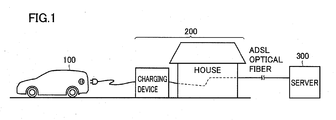
- Fig. 1 is a diagram illustrating an overview of an embodiment of the present invention.
- a vehicle 100 incorporating a power storage device uses the electric power of the power storage device for running and has a configuration which allows the power storage device to be charged from the outside.
- vehicle 100 returns home where it is charged.
- a charging device 200 and vehicle 100 are connected to each other by a charging cable.
- the vehicle obtains the required information when it is connected by the charging cable for charging.
- This information is used for replay, execution, interpretation, and the like on the on-vehicle apparatus and is hereinafter referred to as contents.
- the contents include, for example, information used in the car navigation, music data, a program of a vehicle control ECU, data used by the vehicle control ECU, and the like.
- the information may be obtained by the electric power line communication using the charging cable or by using the communication-dedicated line connected at the same time when the charging cable is connected.
- Charging device 200 downloads the required information from an external server 300 in response to the request from the vehicle side.
- charging device 200 and external server 300 are linked by a high-speed line, such as an ADSL (Asymmetric Digital Subscriber Line) line and an optical fiber line.
- Server 300 is located in the information distribution center external to the house but may be located within the house.
- the communication is performed during charging, which results in an advantage that there is no possibility of a dead battery and the like in contrast to the data communication by a wireless device.
- Vehicle 100 which stores the request for the contents which are felt to be necessary during running, inquires of the driver during charging whether it is intended that the contents are downloaded or not.
- Fig. 2 is a block diagram of a configuration of a vehicle and a charging device shown in greater detail.
- vehicle 100 includes a wheel 108, a motor 106 driving wheel 108, an inverter 104 supplying a three-phase AC (Alternating Current) power to motor 106, a main battery 102 supplying a DC (Direct Current) power to inverter 104, and a main control ECU 114 controlling inverter 104.
- vehicle 100 is an electric vehicle, the present invention can also be applied to the hybrid vehicle and the like in which a motor and an engine are used in combination for driving.
- Vehicle 100 has a configuration that allows main battery 102 to be charged from the outside.
- Vehicle 100 further includes a connector 124 provided with a terminal for feeding, for example, a commercial power supply such as AC 100V from the outside; a charging AC/DC conversion unit 110 converting the AC power supplied to connector 124 to a DC power for supplying it to main battery 102; a switch 122 connecting connector 124 and charging AC/DC conversion unit 110; a connector connection detecting unit 120 detecting that a connector 206 of charging device 200 is connected to connector 124; and an electric power line communication unit 116.
- a connector 124 provided with a terminal for feeding, for example, a commercial power supply such as AC 100V from the outside
- a charging AC/DC conversion unit 110 converting the AC power supplied to connector 124 to a DC power for supplying it to main battery 102
- a switch 122 connecting connector 124 and charging AC/DC conversion unit 110
- a connector connection detecting unit 120 detecting that a connector 206 of charging device 200 is connected to
- Main control ECU 114 monitors a state of charge SOC of main battery 102 and detects the connector connection by connector connection detecting unit 120. If state of charge SOC is lower than a predetermined value when connector 206 is connected to connector 124, main control ECU 114 shifts switch 122 from the opened state to the connected state and operates charging AC/DC conversion unit 110 to charge main battery 102.
- Charging device 200 includes an electric power line communication unit 210 receiving, from the vehicle 100 side, information such as state of charge SOC and a request for electric power feeding; an AC power supply 202; a charging cable 218; connector 206 disposed in the end of charging cable 218; a switch 204 connecting AC power supply 202 to charging cable 218; and a main control ECU 208 controlling the opening and closing of switch 204.
- main control ECU 114 When connector connection detecting unit 120 confirms the connection and main battery 102 is charged, main control ECU 114 requests charging device 200 through electric power line communication unit 116 to feed electric power, or, state of charge SOC may be transmitted from main control ECU 114 through electric power line communication unit 116 to the charging device 200 side to determine the start of electric power feeding based on state of charge SOC on the charging device 200 side.
- main control ECU 208 closes switch 204 to start the electric power feeding, and main control ECU 114 operates charging AC/DC conversion unit 110 to charge main battery 102.
- state of charge SOC of main battery 102 becomes greater than the predetermined value.
- main control ECU 114 stops charging AC/DC conversion unit 110 and shifts switch 122 from the closed state to the opened state and requests charging device 200 through electric power line communication unit 116 to stop the electric power feeding.
- Main control ECU 208 then shifts switch 204 from the closed state to the opened state.
- Vehicle 100 further includes a request storing unit 134 storing contents requesting information in the state where vehicle 100 is not connected to charging device 200 charging main battery 102 from outside the vehicle; and a contents storing unit 136 storing the contents.
- Main control ECU 114 further controls transmission and reception of the contents.
- vehicle 100 is connected to charging device 200 for transmission and reception of electric power in order to charge main battery 102
- main control ECU 114 receives the contents from server 300 based on the contents requesting information stored in request storing unit 134 and stores the received contents in contents storing unit 136.
- Server 300 is located in the information distribution center external to the house but may be located within the house.
- Request storing unit 134 and contents storing unit 136 correspond to first and second storage units, respectively, included in the information apparatus of the vehicle.
- Request storing unit 134 and contents storing unit 136 may be separate recording media or may be different regions in a single recording medium.
- a hard disk drive device, a flash memory, and the like can be used as the recording medium, which may also be accessed by a car navigation device.
- main control ECU 114 Prior to receiving the contents, main control ECU 114 notifies of the content of the contents requesting information to inquire of an operator performing the charging whether he intends to receive the contents based on the contents requesting information.
- main control ECU 114 in cooperation with main control ECU 208 on the charging device side, displays the content of the contents requesting information stored in request storing unit 134 on a display device 214 to confirm whether or not it is intended that the displayed contents are downloaded from the server.
- the operator performing the charging inputs permission or inhibition of the reception of the contents into an input device 212.
- reconfirmation is made before billing for the download cost, to thereby prevent wasteful spending for the user.
- main control ECU 114 receives the contents when the result of the inquiry indicates permission of reception of the contents, and further inquires whether the contents requesting information is deleted or not when the result of the inquiry indicates inhibition of reception of the contents.
- main control ECU 114 deletes the contents requesting information stored in request storing unit 134.
- Vehicle 100 further includes a car navigation system 132.
- main control ECU 114 inquires of the occupant of the vehicle whether the contents are requested or not, and when receiving the instruction from the occupant to request the contents, adds the contents requesting information to request storing unit 134.
- the vehicle may be shown on the display as if it runs in the area with no road. In this case, there is a possibility that a newly constructed road is not shown on the map. Furthermore, in the case where the display shows that the vehicle runs at a speed far exceeding the speed limit in an urban area, a new expressway may be constructed in that area.
- the occupant of the vehicle causes the request to be written on request storing unit 134 even without the above-described inquiry. For example, it is only required that, when the occupant feels it necessary to obtain the detailed map of the area where the occupant frequently visits, it can be added to request storing unit 134 that the detailed map is requested while running in the area.
- the radio station and the date and time on which the music is played may be recorded to refer to the database of the radio station during the charging to specify the music and send a request for the music data to the music distribution server.
- Main control ECU 208 sends a request for the contents to external server 300 via a transmission and reception unit 232 to receive the contents from server 300.
- a temporary storage unit 234 temporarily storing the received contents may be provided.
- Main control ECU 208 transmits the received contents to the vehicle 100 side through electric power line communication unit 210.
- main control ECU 114 receives the contents through electric power line communication unit 116 to write them on contents storing unit 136.
- Fig. 3 is a flowchart of a processing structure of a program relating to the storage of the contents requesting information executed in the vehicle. The process of this flowchart is called for execution from the main routine performed in the state where the vehicle can run at regular time intervals or every time the predetermined conditions are satisfied.
- step S1 main control ECU 114 determines whether the state of car navigation system 132 satisfies the predetermined condition.
- the vehicle may be shown on the display as if it runs in the area with no road. In this case, there is a possibility that a newly constructed road is not shown on the map. Furthermore, in the case where the display shows that the vehicle runs at a speed far exceeding the speed limit in an urban area, a new expressway may be constructed in that area.
- step S1 if it is determined that the state of car navigation system 132 satisfies the predetermined condition, the process goes to step S2.
- step S2 the occupant of the vehicle is inquired whether the contents are requested or not. For example, main control ECU 114 sends to the driver a message such as "a new road may be constructed, is the map to be updated?" by voice or on the display and waits the input indicating whether the map updating is requested or not. The process then goes to step S3.
- step S1 If it is determined in step S1 that the state of car navigation system 132 does not satisfy the predetermined condition, the process goes to step S3.
- step S3 when the instruction to request the contents is received from the occupant, the process goes to step S4 and the contents requesting information is added to request storing unit 134.
- step S3 the occupant of the vehicle can also cause the request to be written on request storing unit 134 even without such an inquiry. For example, it is only required that, when the occupant feels it necessary to obtain the detailed map of the area where the occupant frequently visits, the request from the user that the detailed map is requested while running in the area can be input. More specifically, the driver indicates by a request button that the driver wants to update the map of a certain area (wants to obtain the information about the store and the like around the area).
- step S4 the process goes to step S4, where the content of the request is added to request storing unit 134.
- the radio station and the date and time on which the music is played may be recorded for use as the contents requesting information.
- step S3 If there is no request from the user in step S3 and the process of step S4 is completed, the process goes to step S5 and the control is passed to the main routine.
- Fig. 4 is a flowchart of a processing structure of a program relating to the download of the contents executed during charging.
- step S11 it is determined whether connector 206 is connected to connector 124 and whether there is a charging instruction from a charging operator.
- Main control ECU 114 determines based on the output of connector connection detecting unit 120 as to whether the connectors are connected or not. Furthermore, main control ECU 114 receives the instruction from input device 212 through main control ECU 208, electric power line communication unit 210, charging cable 218, and electric power line communication unit 116 to make a determination as to the charging instruction from the charging operator.
- step S11 In the case where the connectors are not connected to each other or there is no charging instruction in step S11, the process is completed in step S21. In the case where the connectors are connected to each other and there is a charging instruction in step S11, the process goes to step S12.
- main control ECU 114 prior to receiving the contents, notifies of the content of the contents requesting information to inquire of the operator performing the charging whether it is intended to receive the contents based on the contents requesting information.
- Main control ECU 114 in cooperation with main control ECU 208 on the charging device side, displays the content of the contents requesting information stored in request storing unit 134 on display device 214 to confirm whether or not the displayed contents are downloaded from the server.
- the operator performing the charging inputs permission or inhibition of the reception of the contents into input device 212.
- step S 13 it is determined based on the input result whether or not the download of the contents is permitted by the driver or the charging operator. If the download is permitted in step S 13, main control ECU 208 sends a request for the contents to server 300 of the external distribution center through transmission and reception unit 232 in step S 15.
- step S16 main control ECU 208 then receives the contents from server 300.
- the received contents may be temporarily stored in temporary storage unit 234.
- Main control ECU 208 transmits the received contents to the vehicle 100 side through electric power line communication unit 210.
- main control ECU 114 receives the contents through electric power line communication unit 116 to write them on contents storing unit 136 and completes the reception.
- the process goes from step S16 to step S 17.
- the charging operator is further inquired whether the contents requesting information is deleted or not.
- main control ECU 114 deletes the contents requesting information stored in request storing unit 134.
- the contents requesting information was recorded on request storing unit 134 because the information seemed necessary during the vehicle running. However, if such information becomes unnecessary at the time of the charging at home, the contents requesting information is to be deleted.
- step S16 when the reception of the contents is completed and the process goes from step S16 to step S 17, the contents requesting information is not required any more. Thus, the contents requesting information stored in request storing unit 134 is deleted.
- step S 17 When the deletion of the contents requesting information in step S 17 is completed, the process goes to step S 18.
- step S 18 main control ECU 114 requests charging device 200 through electric power line communication unit 116 to feed electric power.
- Main control ECU 114 controls switch 122 to be closed and operates charging AC/DC conversion unit 110 to convert the AC power received from the outside into a DC power for the charging operation of main battery 102.
- control ECU 114 determines in step S 19 whether the state of charge of main battery 102 is smaller than a predetermined threshold value SOC1. If state of charge SOC is smaller than threshold value SOC1, it is determined that the charging needs to be continued and the process returns to step S 18 to continue the charging.
- step S20 main control ECU 114 stops charging AC/DC conversion unit 110 to cause switch 122 to be opened, and requests charging device 200 through electric power line communication unit 116 to stop the electric power feeding, to thereby stop the charging.
- step S21 the charging is completed in step S21. Note that the process of receiving the contents in step S16 may be performed in parallel with the charging process in steps S18 and S19.
- the information of the contents desired to be requested can be collected for record in the state where the vehicle is located away from the charging device. This allows the contents that seemed necessary to be requested without fail. Furthermore, the charging operator does not need to input the required contents as textual information during the charging operation, which can prevent the charging operation from being complicated.
- the download of the contents is performed in parallel with the charging, it is less likely to cause an interruption of the download due to a dead battery as in the data communication using the wireless device.
- the example in which the communication and the transmission of the contents between the charging device and vehicle 100 are performed by the electric power line communication has been described, which may be, however, performed using the communication-dedicated line integrated into the cable in parallel with the electric power line. Even in this case, if the connector is structured such that both of the electric power line and the communication line are in the connected states when a plug is connected for charging, the operation of the charging operator can be prevented from being complicated.
- the contents are navigation information, music, and the like.
- the contents are the program executed by a vehicle ECU, the data to be referred, and the like.
- the vehicle ECU detects the abnormality during running to perform failure diagnosis.
- the history of the output of these sensors and the history of the failure diagnosis are stored as "information-related data" in the first storage unit.
- the information such as a program solving problems resulting from failure, a map, and the like is stored in the second storage unit, and is executed and referred by the vehicle ECU.
- the determination may be made by the ECU inside the vehicle as to whether new information is read into the second storage unit based on the "information-related data”, but may be made outside the vehicle based on the "information-related data", which is sent to the external device, suggesting the need for new information.
- Fig. 2 shows, as an example of a rechargeable vehicle, an electric vehicle in which the motor drives the wheels.
- the present invention may be applied to a series/parallel type hybrid vehicle in which the power of the engine can be divided by the power split device for transmission into the axle and the power generator, and also to a series type hybrid vehicle in which the driving force of the axle is generated only by the motor using the electric power generated by the power generator.
- the battery may be charged from the outside in these configurations to which the present invention is applicable.
- the configuration in which the electric device external to the vehicle corresponds to a charging device which includes an AC power supply has been described as an example, which may also be a configuration in which the charging device has a DC power supply.
- AC power supply 202 is replaced with a DC power supply
- charging AC/DC conversion unit 110 is replaced with a DC/DC conversion unit.
- the electric device external to the vehicle may receive electric power from the vehicle.
- charging AC/DC conversion unit 110 in Fig. 2 is replaced with an AC/DC conversion unit converting the DC power received from the battery and the on-vehicle power generator into an AC power for supply to the outside.
- charging AC/DC conversion unit 110 in Fig. 2 is replaced with a DC/DC conversion unit receiving the DC power from the battery and the on-vehicle power generator to perform voltage conversion for supply to the outside.
- the hybrid vehicle can be used as a power supply device in case of emergency.
Abstract
Description
- The present invention relates to a vehicle and an information apparatus thereof, and particularly to a vehicle and an information apparatus thereof having a device capable of transmitting and receiving electric power to and from an external device.
- As an environmentally-friendly vehicle, an electric vehicle, a hybrid vehicle, a fuel cell vehicle, and the like incorporating a power storage device and also incorporating a motor as a driving device have attracted attention in recent years. It is also considered that the hybrid vehicle is configured to be rechargeable from the outside.
- Japanese Patent Laying-Open No.
2004-222176 - An example of information required on the vehicle side includes a road map of the car navigation system, music information, and the like, which are often required during vehicle running.
- In order to receive data in real time during vehicle running, it is considered that, for example, the wireless communication is performed between the distribution center storing the information and the vehicle. However, the wireless communication greatly depends on the conditions of the communication infrastructure and also involves various constraints.
- However, in the method of receiving the information distribution through the electric power supply line during the charging of the vehicle as disclosed in Japanese Patent Laying-Open No.
2004-222176 - An object of the present invention is to provide a vehicle and an information apparatus of the vehicle that allow the information with its possible necessity being suggested to be reliably requested.
- In summary, the present invention provides a vehicle having an apparatus using information and having an electric power transmitting and receiving device transmitting and receiving electric power to and from an external device external to the vehicle. The vehicle includes a first storage unit storing data related to the information used in the apparatus in the state where the external device and the vehicle are not connected to each other; a second storage unit storing the information; detecting means for detecting a connected state of the vehicle to a charging device; and control means for, when the detecting means detect the connected state, obtaining the information to store in the second storage unit from outside the vehicle based on the related data stored in the first storage unit.
- Preferably, the control unit notifies of a content of the related data prior to receiving the information to inquire of an operator connecting the vehicle and the external device whether the information is received based on the related data.
- More preferably, the control unit receives the information when the result of the inquiry indicates permission of reception of the information, and further inquires whether the related data is deleted when the result of the inquiry indicates inhibition of reception of the information.
- Preferably, the vehicle further includes a car navigation device. The control unit, when the state of the car navigation device satisfies a predetermined condition, inquires of an occupant of the vehicle whether to obtain the information, and, when receiving an instruction from the occupant to obtain the information, adds a request for the information as related data to the first storage unit.
- Preferably, the vehicle and the external device are connected by a cable for transmitting and receiving the electric power, and the information is stored in the second storage unit through the cable.
- More preferably, the related data is transmitted through the cable.
- According to another aspect, the present invention provides an information apparatus of a vehicle using information and mounted in the vehicle having an electric power transmitting and receiving device transmitting and receiving electric power to and from an external device external to the vehicle. The information apparatus includes a first storage unit storing data related to the information used in the information apparatus in the state where the external device and the vehicle are not connected to each other; a second storage unit storing the information; detecting means for detecting a connected state of the vehicle to a charging device; and control means for, when the detecting means detect the connected state, obtaining the information to store in the second storage unit from outside the vehicle based on the related data stored in the first storage unit.
- Preferably, the control unit notifies of a content of the related data prior to receiving the information to inquire of an operator connecting the vehicle and the external device whether the information is received based on the related data.
- More preferably, the control unit receives the information when the result of the inquiry indicates permission of reception of the information, and further inquires whether the related data is deleted when the result of the inquiry indicates inhibition of reception of the information.
- Preferably, the information apparatus further includes a car navigation device. The control unit, when the state of the car navigation device satisfies a predetermined condition, inquires of an occupant of the vehicle whether to obtain the information, and, when receiving an instruction from the occupant to obtain the information, adds a request for the information as related data to the first storage unit.
- Preferably, the vehicle and the external device are connected by a cable for transmitting and receiving the electric power, and the information is stored in the second storage unit through the cable.
- More preferably, the related data is transmitted through the cable.
- According to the present invention, the information with its possible necessity being suggested during running can be requested with reliability.
-
-
Fig. 1 is a diagram illustrating an overview of an embodiment of the present invention. -
Fig. 2 is a block diagram of a configuration of a vehicle and a charging device shown in greater detail. -
Fig. 3 is a flowchart of a processing structure of a program relating to the storage of contents requesting information executed in the vehicle. -
Fig. 4 is a flowchart of a processing structure of a program relating to the download of the contents executed during charging. - The embodiments of the present invention will be hereinafter described in detail with reference to the accompanying drawings, in which the same or corresponding components are designated by the same reference characters, and description thereof will not be repeated.
-
Fig. 1 is a diagram illustrating an overview of an embodiment of the present invention. - Referring to
Fig. 1 , avehicle 100 incorporating a power storage device uses the electric power of the power storage device for running and has a configuration which allows the power storage device to be charged from the outside. - For example,
vehicle 100 returns home where it is charged. Acharging device 200 andvehicle 100 are connected to each other by a charging cable. - The vehicle obtains the required information when it is connected by the charging cable for charging. This information is used for replay, execution, interpretation, and the like on the on-vehicle apparatus and is hereinafter referred to as contents. The contents include, for example, information used in the car navigation, music data, a program of a vehicle control ECU, data used by the vehicle control ECU, and the like. The information may be obtained by the electric power line communication using the charging cable or by using the communication-dedicated line connected at the same time when the charging cable is connected.
-
Charging device 200 downloads the required information from anexternal server 300 in response to the request from the vehicle side. For example,charging device 200 andexternal server 300 are linked by a high-speed line, such as an ADSL (Asymmetric Digital Subscriber Line) line and an optical fiber line.Server 300 is located in the information distribution center external to the house but may be located within the house. - The communication is performed during charging, which results in an advantage that there is no possibility of a dead battery and the like in contrast to the data communication by a wireless device.
-
Vehicle 100, which stores the request for the contents which are felt to be necessary during running, inquires of the driver during charging whether it is intended that the contents are downloaded or not. -
Fig. 2 is a block diagram of a configuration of a vehicle and a charging device shown in greater detail. - Referring to
Figs. 1 and2 ,vehicle 100 includes awheel 108, amotor 106driving wheel 108, aninverter 104 supplying a three-phase AC (Alternating Current) power tomotor 106, amain battery 102 supplying a DC (Direct Current) power to inverter 104, and a main control ECU 114 controllinginverter 104. In other words, althoughvehicle 100 is an electric vehicle, the present invention can also be applied to the hybrid vehicle and the like in which a motor and an engine are used in combination for driving. -
Vehicle 100 has a configuration that allowsmain battery 102 to be charged from the outside.Vehicle 100 further includes aconnector 124 provided with a terminal for feeding, for example, a commercial power supply such as AC 100V from the outside; a charging AC/DC conversion unit 110 converting the AC power supplied toconnector 124 to a DC power for supplying it tomain battery 102; aswitch 122 connectingconnector 124 and charging AC/DC conversion unit 110; a connectorconnection detecting unit 120 detecting that aconnector 206 ofcharging device 200 is connected toconnector 124; and an electric powerline communication unit 116. -
Main control ECU 114 monitors a state of charge SOC ofmain battery 102 and detects the connector connection by connectorconnection detecting unit 120. If state of charge SOC is lower than a predetermined value whenconnector 206 is connected toconnector 124,main control ECU 114shifts switch 122 from the opened state to the connected state and operates charging AC/DC conversion unit 110 to chargemain battery 102. -
Charging device 200 includes an electric powerline communication unit 210 receiving, from thevehicle 100 side, information such as state of charge SOC and a request for electric power feeding; anAC power supply 202; acharging cable 218;connector 206 disposed in the end ofcharging cable 218; aswitch 204 connectingAC power supply 202 tocharging cable 218; and amain control ECU 208 controlling the opening and closing ofswitch 204. - When connector
connection detecting unit 120 confirms the connection andmain battery 102 is charged,main control ECU 114requests charging device 200 through electric powerline communication unit 116 to feed electric power, or, state of charge SOC may be transmitted frommain control ECU 114 through electric powerline communication unit 116 to thecharging device 200 side to determine the start of electric power feeding based on state of charge SOC on thecharging device 200 side. - When
vehicle 100requests charging device 200 to feed electric power, main control ECU 208 closesswitch 204 to start the electric power feeding, and main control ECU 114 operates charging AC/DC conversion unit 110 to chargemain battery 102. - As the charging is completed, state of charge SOC of
main battery 102 becomes greater than the predetermined value. In accordance therewith,main control ECU 114 stops charging AC/DC conversion unit 110 and shiftsswitch 122 from the closed state to the opened state and requestscharging device 200 through electric powerline communication unit 116 to stop the electric power feeding.Main control ECU 208 then shiftsswitch 204 from the closed state to the opened state. -
Vehicle 100 further includes arequest storing unit 134 storing contents requesting information in the state wherevehicle 100 is not connected tocharging device 200 chargingmain battery 102 from outside the vehicle; and acontents storing unit 136 storing the contents. -
Main control ECU 114 further controls transmission and reception of the contents. Whenvehicle 100 is connected to chargingdevice 200 for transmission and reception of electric power in order to chargemain battery 102,main control ECU 114 receives the contents fromserver 300 based on the contents requesting information stored inrequest storing unit 134 and stores the received contents incontents storing unit 136.Server 300 is located in the information distribution center external to the house but may be located within the house. -
Request storing unit 134 andcontents storing unit 136 correspond to first and second storage units, respectively, included in the information apparatus of the vehicle.Request storing unit 134 andcontents storing unit 136 may be separate recording media or may be different regions in a single recording medium. A hard disk drive device, a flash memory, and the like can be used as the recording medium, which may also be accessed by a car navigation device. - Prior to receiving the contents,
main control ECU 114 notifies of the content of the contents requesting information to inquire of an operator performing the charging whether he intends to receive the contents based on the contents requesting information. - For example,
main control ECU 114, in cooperation withmain control ECU 208 on the charging device side, displays the content of the contents requesting information stored inrequest storing unit 134 on adisplay device 214 to confirm whether or not it is intended that the displayed contents are downloaded from the server. The operator performing the charging inputs permission or inhibition of the reception of the contents into aninput device 212. There are many cases where a certain time has passed since the contents requesting information was stored. Thus, reconfirmation is made before billing for the download cost, to thereby prevent wasteful spending for the user. - More preferably,
main control ECU 114 receives the contents when the result of the inquiry indicates permission of reception of the contents, and further inquires whether the contents requesting information is deleted or not when the result of the inquiry indicates inhibition of reception of the contents. When an instruction to delete the contents requesting information is input frominput device 212,main control ECU 114 deletes the contents requesting information stored inrequest storing unit 134. - The contents requesting information is stored in
request storing unit 134 when the occupant feels it necessary while riding in the vehicle.Vehicle 100 further includes acar navigation system 132. When the state ofcar navigation system 132 satisfies the predetermined condition,main control ECU 114 inquires of the occupant of the vehicle whether the contents are requested or not, and when receiving the instruction from the occupant to request the contents, adds the contents requesting information to request storingunit 134. - For example, during the vehicle running in the state where the surrounding map and the vehicle location are displayed on the display by the car navigation system, the vehicle may be shown on the display as if it runs in the area with no road. In this case, there is a possibility that a newly constructed road is not shown on the map. Furthermore, in the case where the display shows that the vehicle runs at a speed far exceeding the speed limit in an urban area, a new expressway may be constructed in that area.
- This is the case where the state of
car navigation system 132 satisfies the predetermined condition, in whichmain control ECU 114 sends to the driver a message such as "a new road may be constructed, is the map to be updated?" by voice or on the display and waits the input indicating whether the map updating is requested or not. - It can also be considered that the occupant of the vehicle causes the request to be written on
request storing unit 134 even without the above-described inquiry. For example, it is only required that, when the occupant feels it necessary to obtain the detailed map of the area where the occupant frequently visits, it can be added to request storingunit 134 that the detailed map is requested while running in the area. In addition, for example, when a favorite music is played on the radio, the radio station and the date and time on which the music is played may be recorded to refer to the database of the radio station during the charging to specify the music and send a request for the music data to the music distribution server. - When the above-described request is established, the contents are downloaded in charging
device 200 before, in parallel with, or after the charging.Main control ECU 208 sends a request for the contents toexternal server 300 via a transmission andreception unit 232 to receive the contents fromserver 300. Atemporary storage unit 234 temporarily storing the received contents may be provided.Main control ECU 208 transmits the received contents to thevehicle 100 side through electric powerline communication unit 210. On the vehicle side,main control ECU 114 receives the contents through electric powerline communication unit 116 to write them oncontents storing unit 136. -
Fig. 3 is a flowchart of a processing structure of a program relating to the storage of the contents requesting information executed in the vehicle. The process of this flowchart is called for execution from the main routine performed in the state where the vehicle can run at regular time intervals or every time the predetermined conditions are satisfied. - Referring to
Figs. 2 and3 , when the process is first started, in step S1,main control ECU 114 determines whether the state ofcar navigation system 132 satisfies the predetermined condition. - For example, during the vehicle running in the state where the surrounding map and the vehicle location are displayed on the display by the car navigation system, the vehicle may be shown on the display as if it runs in the area with no road. In this case, there is a possibility that a newly constructed road is not shown on the map. Furthermore, in the case where the display shows that the vehicle runs at a speed far exceeding the speed limit in an urban area, a new expressway may be constructed in that area.
- This is the case where the state of
car navigation system 132 satisfies the predetermined condition. - In step S1, if it is determined that the state of
car navigation system 132 satisfies the predetermined condition, the process goes to step S2. - In step S2, the occupant of the vehicle is inquired whether the contents are requested or not. For example,
main control ECU 114 sends to the driver a message such as "a new road may be constructed, is the map to be updated?" by voice or on the display and waits the input indicating whether the map updating is requested or not. The process then goes to step S3. - If it is determined in step S1 that the state of
car navigation system 132 does not satisfy the predetermined condition, the process goes to step S3. - In the case where the process goes from step S2 to step S3, when the instruction to request the contents is received from the occupant, the process goes to step S4 and the contents requesting information is added to request storing
unit 134. - Furthermore, in step S3, the occupant of the vehicle can also cause the request to be written on
request storing unit 134 even without such an inquiry. For example, it is only required that, when the occupant feels it necessary to obtain the detailed map of the area where the occupant frequently visits, the request from the user that the detailed map is requested while running in the area can be input. More specifically, the driver indicates by a request button that the driver wants to update the map of a certain area (wants to obtain the information about the store and the like around the area). - Also in this case, the process goes to step S4, where the content of the request is added to request storing
unit 134. In addition, for example, when a favorite music is played on the radio, the radio station and the date and time on which the music is played may be recorded for use as the contents requesting information. - If there is no request from the user in step S3 and the process of step S4 is completed, the process goes to step S5 and the control is passed to the main routine.
-
Fig. 4 is a flowchart of a processing structure of a program relating to the download of the contents executed during charging. - Referring to
Figs. 2 and4 , as the process is first started, in step S11, it is determined whetherconnector 206 is connected toconnector 124 and whether there is a charging instruction from a charging operator.Main control ECU 114 determines based on the output of connectorconnection detecting unit 120 as to whether the connectors are connected or not. Furthermore,main control ECU 114 receives the instruction frominput device 212 throughmain control ECU 208, electric powerline communication unit 210, chargingcable 218, and electric powerline communication unit 116 to make a determination as to the charging instruction from the charging operator. - In the case where the connectors are not connected to each other or there is no charging instruction in step S11, the process is completed in step S21. In the case where the connectors are connected to each other and there is a charging instruction in step S11, the process goes to step S12.
- In step S12, prior to receiving the contents,
main control ECU 114 notifies of the content of the contents requesting information to inquire of the operator performing the charging whether it is intended to receive the contents based on the contents requesting information.Main control ECU 114, in cooperation withmain control ECU 208 on the charging device side, displays the content of the contents requesting information stored inrequest storing unit 134 ondisplay device 214 to confirm whether or not the displayed contents are downloaded from the server. The operator performing the charging inputs permission or inhibition of the reception of the contents intoinput device 212. - In step S 13, it is determined based on the input result whether or not the download of the contents is permitted by the driver or the charging operator. If the download is permitted in step S 13,
main control ECU 208 sends a request for the contents toserver 300 of the external distribution center through transmission andreception unit 232 in step S 15. - In step S16,
main control ECU 208 then receives the contents fromserver 300. The received contents may be temporarily stored intemporary storage unit 234.Main control ECU 208 transmits the received contents to thevehicle 100 side through electric powerline communication unit 210. On the vehicle side,main control ECU 114 receives the contents through electric powerline communication unit 116 to write them oncontents storing unit 136 and completes the reception. When the reception of the contents is completed, the process goes from step S16 to step S 17. - On the other hand, in the case where the process goes from step S 13 to step S 14, the charging operator is further inquired whether the contents requesting information is deleted or not. When
input device 212 inputs the instruction to delete the contents requesting information,main control ECU 114 deletes the contents requesting information stored inrequest storing unit 134. For example, the contents requesting information was recorded onrequest storing unit 134 because the information seemed necessary during the vehicle running. However, if such information becomes unnecessary at the time of the charging at home, the contents requesting information is to be deleted. - Furthermore, when the reception of the contents is completed and the process goes from step S16 to step S 17, the contents requesting information is not required any more. Thus, the contents requesting information stored in
request storing unit 134 is deleted. - When the deletion of the contents requesting information in step S 17 is completed, the process goes to step S 18.
- Although the contents presented by the contents requesting information is not downloaded at this time, for example, in consideration of the cost, it is also conceivable that the contents requesting information is desired to be remained in
request storing unit 134 in order to allow for a future download. In this case, the process goes from step S 14 to step S18. - In step S 18,
main control ECU 114requests charging device 200 through electric powerline communication unit 116 to feed electric power.Main control ECU 114 then controls switch 122 to be closed and operates charging AC/DC conversion unit 110 to convert the AC power received from the outside into a DC power for the charging operation ofmain battery 102. - During charging,
control ECU 114 determines in step S 19 whether the state of charge ofmain battery 102 is smaller than a predetermined threshold value SOC1. If state of charge SOC is smaller than threshold value SOC1, it is determined that the charging needs to be continued and the process returns to step S 18 to continue the charging. - In the case where state of charge SOC is not less than predetermined threshold value SOC1 in step S19, the process goes to step S20. In step S20,
main control ECU 114 stops charging AC/DC conversion unit 110 to causeswitch 122 to be opened, andrequests charging device 200 through electric powerline communication unit 116 to stop the electric power feeding, to thereby stop the charging. When the process of step S20 is finished, the charging is completed in step S21. Note that the process of receiving the contents in step S16 may be performed in parallel with the charging process in steps S18 and S19. - As described above, in the present embodiment, the information of the contents desired to be requested can be collected for record in the state where the vehicle is located away from the charging device. This allows the contents that seemed necessary to be requested without fail. Furthermore, the charging operator does not need to input the required contents as textual information during the charging operation, which can prevent the charging operation from being complicated.
- Furthermore, if the download of the contents is performed in parallel with the charging, it is less likely to cause an interruption of the download due to a dead battery as in the data communication using the wireless device.
- In the present embodiment, the example in which the communication and the transmission of the contents between the charging device and
vehicle 100 are performed by the electric power line communication has been described, which may be, however, performed using the communication-dedicated line integrated into the cable in parallel with the electric power line. Even in this case, if the connector is structured such that both of the electric power line and the communication line are in the connected states when a plug is connected for charging, the operation of the charging operator can be prevented from being complicated. - The case where the contents are navigation information, music, and the like has been described in the above. In addition to this, it is also conceivable that the contents are the program executed by a vehicle ECU, the data to be referred, and the like.
- In the case where the sensor (for example, an air-fuel ratio sensor provided in the vicinity of the exhaust gas purification catalyst, a current sensor for motor control, voltage and current sensors within the battery monitoring unit, and the like) incorporated in the vehicle indicates abnormality, the vehicle ECU detects the abnormality during running to perform failure diagnosis. The history of the output of these sensors and the history of the failure diagnosis are stored as "information-related data" in the first storage unit.
- When the vehicle is connected to an external device for charging and the like, the information such as a program solving problems resulting from failure, a map, and the like is stored in the second storage unit, and is executed and referred by the vehicle ECU. Note that the determination may be made by the ECU inside the vehicle as to whether new information is read into the second storage unit based on the "information-related data", but may be made outside the vehicle based on the "information-related data", which is sent to the external device, suggesting the need for new information.
- In the present embodiment,
Fig. 2 shows, as an example of a rechargeable vehicle, an electric vehicle in which the motor drives the wheels. However, the present invention may be applied to a series/parallel type hybrid vehicle in which the power of the engine can be divided by the power split device for transmission into the axle and the power generator, and also to a series type hybrid vehicle in which the driving force of the axle is generated only by the motor using the electric power generated by the power generator. The battery may be charged from the outside in these configurations to which the present invention is applicable. - In the above-described embodiments, the configuration in which the electric device external to the vehicle corresponds to a charging device which includes an AC power supply has been described as an example, which may also be a configuration in which the charging device has a DC power supply. In this case, for example in
Fig. 2 ,AC power supply 202 is replaced with a DC power supply and charging AC/DC conversion unit 110 is replaced with a DC/DC conversion unit. - Furthermore, the electric device external to the vehicle may receive electric power from the vehicle. In this case, for example, charging AC/
DC conversion unit 110 inFig. 2 is replaced with an AC/DC conversion unit converting the DC power received from the battery and the on-vehicle power generator into an AC power for supply to the outside. In addition, for example, in the case where the DC power is supplied to the outside, charging AC/DC conversion unit 110 inFig. 2 is replaced with a DC/DC conversion unit receiving the DC power from the battery and the on-vehicle power generator to perform voltage conversion for supply to the outside. In particular, the hybrid vehicle can be used as a power supply device in case of emergency. - It should be understood that the embodiments disclosed herein are illustrative and non-restrictive in every respect. The scope of the present invention is defined by the terms of the claims, rather than the description above, and is intended to include any modifications within the scope and meaning equivalent to the terms of the claims.
Claims (12)
- A vehicle having an apparatus using information and having an electric power transmitting and receiving device transmitting and receiving electric power to and from an external device external to the vehicle, comprising:a first storage unit storing data related to said information used in said apparatus in a state where said external device and said vehicle are not connected to each other;a second storage unit storing said information;detecting means for detecting a connected state of said vehicle to said charging device; andcontrol means for, when said detecting means detect the connected state, obtaining said information to store in said second storage unit from outside the vehicle based on said related data stored in said first storage unit.
- The vehicle according to claim 1, wherein said control unit notifies of a content of said related data prior to receiving said information to inquire of an operator connecting said vehicle and said external device whether said information is received based on said related data.
- The vehicle according to claim 2, wherein said control unit receives said information when a result of said inquiry indicates permission of reception of said information, and further inquires whether said related data is deleted when the result of said inquiry indicates inhibition of reception of said information.
- The vehicle according to claim 1, further comprising a car navigation device, wherein
said control unit, when a state of said car navigation device satisfies a predetermined condition, inquires of an occupant of said vehicle whether to obtain said information, and, when receiving an instruction from said occupant to obtain said information, adds a request for said information as related data to said first storage unit. - The vehicle according to claim 1, wherein
said vehicle and said external device are connected by a cable for transmitting and receiving electric power, and
said information is stored in said second storage unit through said cable. - The vehicle according to claim 5, wherein said related data is transmitted through said cable.
- An information apparatus of a vehicle using information and mounted in the vehicle having an electric power transmitting and receiving device transmitting and receiving electric power to and from an external device external to the vehicle, comprising:a first storage unit storing data related to said information used in said information apparatus in a state where said external device and said vehicle are not connected to each other;a second storage unit storing said information;detecting means for detecting a connected state of said vehicle to said charging device; andcontrol means for, when said detecting means detect the connected state, obtaining said information to store in said second storage unit from outside the vehicle based on said related data stored in said first storage unit.
- The information apparatus of the vehicle according to claim 7, wherein said control unit notifies of a content of said related data prior to receiving said information to inquire of an operator connecting said vehicle and said external device whether said information is received based on said related data.
- The information apparatus of the vehicle according to claim 8, wherein said control unit receives said information when a result of said inquiry indicates permission of reception of said information, and further inquires whether said related data is deleted when the result of said inquiry indicates inhibition of reception of said information.
- The information apparatus of the vehicle according to claim 7, further comprising a car navigation device, wherein
said control unit, when a state of said car navigation device satisfies a predetermined condition, inquires of an occupant of said vehicle whether to obtain said information, and, when receiving an instruction from said occupant to obtain said information, adds a request for said information as related data to said first storage unit. - The information apparatus of the vehicle according to claim 7, wherein said vehicle and said external device are connected by a cable for transmitting and receiving electric power, and
said information is stored in said second storage unit through said cable. - The information apparatus of the vehicle according to claim 11, wherein said related data is transmitted through said cable.
Applications Claiming Priority (2)
| Application Number | Priority Date | Filing Date | Title |
|---|---|---|---|
| JP2006058394A JP4962939B2 (en) | 2006-03-03 | 2006-03-03 | Vehicles and vehicle information devices |
| PCT/JP2007/053993 WO2007100073A1 (en) | 2006-03-03 | 2007-02-23 | Vehicle and vehicle information device |
Publications (2)
| Publication Number | Publication Date |
|---|---|
| EP1992524A1 true EP1992524A1 (en) | 2008-11-19 |
| EP1992524A4 EP1992524A4 (en) | 2016-05-11 |
Family
ID=38459168
Family Applications (1)
| Application Number | Title | Priority Date | Filing Date |
|---|---|---|---|
| EP07715143.9A Withdrawn EP1992524A4 (en) | 2006-03-03 | 2007-02-23 | Vehicle and vehicle information device |
Country Status (5)
| Country | Link |
|---|---|
| US (1) | US7994908B2 (en) |
| EP (1) | EP1992524A4 (en) |
| JP (1) | JP4962939B2 (en) |
| CN (1) | CN101395039B (en) |
| WO (1) | WO2007100073A1 (en) |
Cited By (7)
| Publication number | Priority date | Publication date | Assignee | Title |
|---|---|---|---|---|
| EP2527185A1 (en) * | 2010-01-18 | 2012-11-28 | Toyota Jidosha Kabushiki Kaisha | Display system for vehicle, and vehicle with same |
| US8594886B2 (en) | 2008-12-19 | 2013-11-26 | Pioneer Corporation | Car-mounted information apparatus and information transfer system for electric car |
| EP2692570A4 (en) * | 2011-03-29 | 2015-11-18 | Panasonic Ip Man Co Ltd | In-vehicle charging device |
| DE102014119623A1 (en) | 2014-12-23 | 2016-06-23 | Pintsch Bamag Antriebs- Und Verkehrstechnik Gmbh | LED light module, signal light with such a light module and method for operating such a light module |
| EP3499733A3 (en) * | 2017-12-15 | 2019-07-03 | The Boeing Company | Method and apparatus for physical security over a powerline connection |
| DE102010000387B4 (en) | 2009-02-16 | 2021-12-30 | Denso Corporation | Remote monitoring system for a vehicle with an electrical connection |
| US11323435B2 (en) | 2019-05-08 | 2022-05-03 | The Boeing Company | Method and apparatus for advanced security systems over a power line connection |
Families Citing this family (37)
| Publication number | Priority date | Publication date | Assignee | Title |
|---|---|---|---|---|
| JP4840337B2 (en) * | 2007-11-23 | 2011-12-21 | 株式会社デンソー | Water heater, door phone and vehicle charging device |
| JP4872905B2 (en) * | 2007-12-21 | 2012-02-08 | 株式会社デンソー | Vehicle power line communication system and vehicle plug |
| JP2009166769A (en) * | 2008-01-18 | 2009-07-30 | Denso Corp | Power system of on-vehicle device |
| JP5194964B2 (en) * | 2008-04-07 | 2013-05-08 | 日本電気株式会社 | Electric vehicle battery charging system |
| JP2010103870A (en) * | 2008-10-27 | 2010-05-06 | Pioneer Electronic Corp | On-vehicle information device, vehicle-external information device, electric vehicle charging system, and method for transferring information of electric vehicle charging system |
| JP5344895B2 (en) * | 2008-12-10 | 2013-11-20 | 矢崎総業株式会社 | Charge monitoring device |
| JP4714798B2 (en) * | 2008-12-19 | 2011-06-29 | パイオニア株式会社 | In-vehicle information device and information transfer system for electric vehicle |
| JP4714802B2 (en) * | 2008-12-19 | 2011-06-29 | パイオニア株式会社 | In-vehicle information device and information transfer system for electric vehicle |
| US8564403B2 (en) * | 2009-03-18 | 2013-10-22 | Mario Landau-Holdsworth | Method, system, and apparatus for distributing electricity to electric vehicles, monitoring the distribution thereof, and/or controlling the distribution thereof |
| JP5402185B2 (en) * | 2009-04-13 | 2014-01-29 | 株式会社デンソー | Charge monitoring device, electric vehicle, and server |
| JP2010254031A (en) | 2009-04-22 | 2010-11-11 | Denso Corp | Inter-vehicle communication device |
| WO2010137307A1 (en) * | 2009-05-26 | 2010-12-02 | 日立オートモティブシステムズ株式会社 | Vehicle operation support system and vehicle operation support method |
| JP5560788B2 (en) * | 2009-06-26 | 2014-07-30 | 日産自動車株式会社 | Information provision device |
| JP5490473B2 (en) * | 2009-09-15 | 2014-05-14 | ルネサスエレクトロニクス株式会社 | Data processing system, electric vehicle and maintenance service system |
| WO2011092854A1 (en) * | 2010-01-29 | 2011-08-04 | パイオニア株式会社 | Information provision device, information processing device, information provision method, information acquisition method, information provision program, information acquisition program, and recording medium |
| US8541903B2 (en) * | 2010-02-03 | 2013-09-24 | Panasonic Automotive Systems Company Of America, Division Of Panasonic Corporation Of North America | Power line communication system and method |
| WO2011104883A1 (en) * | 2010-02-26 | 2011-09-01 | パイオニア株式会社 | Data providing device, data providing method, data providing program, and recording medium |
| JP5604181B2 (en) * | 2010-05-31 | 2014-10-08 | トヨタホーム株式会社 | Charger |
| US20110302078A1 (en) | 2010-06-02 | 2011-12-08 | Bryan Marc Failing | Managing an energy transfer between a vehicle and an energy transfer system |
| JP5164184B2 (en) * | 2010-07-27 | 2013-03-13 | トヨタ自動車株式会社 | Energy management system |
| DE102010039326A1 (en) * | 2010-08-13 | 2012-02-16 | Sb Limotive Company Ltd. | Method for determining a state of charge of a battery |
| JP5573495B2 (en) * | 2010-08-25 | 2014-08-20 | 株式会社デンソー | In-vehicle data communication device |
| US9623761B2 (en) * | 2010-12-22 | 2017-04-18 | Ford Global Technologies, Llc | Vehicle and method for authenticating a charge station |
| JP5533785B2 (en) * | 2011-05-27 | 2014-06-25 | 株式会社デンソー | Charger |
| JP5662248B2 (en) * | 2011-05-30 | 2015-01-28 | 富士通テン株式会社 | In-vehicle system |
| WO2013016545A2 (en) | 2011-07-26 | 2013-01-31 | Gogoro, Inc. | Apparatus, method and article for providing vehicle diagnostic data |
| KR101294533B1 (en) * | 2011-12-23 | 2013-08-07 | 현대자동차주식회사 | System and method for sending/receiving data at charing EV |
| JP2013148392A (en) * | 2012-01-17 | 2013-08-01 | Denso Corp | Vehicle apparatus and traveling route guidance system |
| KR20130100822A (en) * | 2012-02-01 | 2013-09-12 | 에스케이플래닛 주식회사 | System for providing contents and advertisement of electric vehicle, method thereof and apparatus thereof |
| JP5935388B2 (en) * | 2012-02-29 | 2016-06-15 | 日産自動車株式会社 | Movement restriction device when charging cable of vehicle is connected |
| JP2013256200A (en) * | 2012-06-12 | 2013-12-26 | Hitoshi Ishida | Energy replenishment and supply system, energy supply device, and mobile body |
| US9184778B2 (en) * | 2013-02-22 | 2015-11-10 | Nissan North America, Inc. | Vehicle information gathering system |
| KR101548948B1 (en) * | 2013-03-08 | 2015-09-03 | 주식회사 케이티 | Method and system for providing electric vehicle in charging with contents |
| JP5761265B2 (en) | 2013-07-30 | 2015-08-12 | 株式会社デンソー | Vehicle charge control device |
| JP6135409B2 (en) * | 2013-09-04 | 2017-05-31 | 株式会社デンソー | Current sensor abnormality detection method and vehicle |
| KR101459968B1 (en) * | 2013-11-19 | 2014-11-10 | 현대자동차주식회사 | Charging demand verification method of a Electric Vehicle and the system thereof |
| DE102013225748B4 (en) | 2013-12-12 | 2022-01-27 | Volkswagen Aktiengesellschaft | Mobile unit and method for using an electrochemical energy store as required |
Family Cites Families (17)
| Publication number | Priority date | Publication date | Assignee | Title |
|---|---|---|---|---|
| JPH06343202A (en) * | 1993-06-01 | 1994-12-13 | Nissan Motor Co Ltd | Electric car battery charger |
| US5572204A (en) * | 1995-04-10 | 1996-11-05 | Ford Motor Company | Vehicular emergency message system |
| JP3591229B2 (en) * | 1997-07-04 | 2004-11-17 | トヨタ自動車株式会社 | Software maintenance system and on-board terminal software maintenance system |
| JP3985390B2 (en) | 1999-06-17 | 2007-10-03 | 日産自動車株式会社 | Power management system |
| JP4164996B2 (en) * | 2000-01-05 | 2008-10-15 | 日産自動車株式会社 | Power management system |
| AU2001244816A1 (en) * | 2000-03-30 | 2001-10-23 | Jung-Hyun Kho | Sideview mirror apparatus for vehicles |
| JP2002005669A (en) * | 2000-06-16 | 2002-01-09 | Mitsubishi Electric Corp | Computer-readable and rewritable recording medium, map information-updating system and navigation apparatus |
| JP2002271248A (en) * | 2001-03-08 | 2002-09-20 | Hitachi Ltd | Portable terminal connecting equipment and its operating program |
| JP3717420B2 (en) * | 2001-04-27 | 2005-11-16 | シャープ株式会社 | Mobile outlet, power supply gate device, server device, and power usage management system |
| JP2003069731A (en) * | 2001-08-29 | 2003-03-07 | Mitsubishi Electric Corp | Remote equipment state monitoring system |
| JP2003274386A (en) * | 2002-03-19 | 2003-09-26 | Linguamaster Kk | Content receiving device and download system including the same |
| CN100481786C (en) * | 2002-08-09 | 2009-04-22 | 爱信艾达株式会社 | Power management system for communication device |
| JP4124044B2 (en) * | 2002-08-09 | 2008-07-23 | アイシン・エィ・ダブリュ株式会社 | Boot management system |
| JP2004096973A (en) * | 2002-09-04 | 2004-03-25 | Kenwood Corp | Data acquisition system |
| JP2004157909A (en) | 2002-11-08 | 2004-06-03 | Internet Broadcast:Kk | Rental system for content communication and content use instrument |
| JP2004222176A (en) * | 2003-01-17 | 2004-08-05 | Sony Corp | Communication system and communication method |
| CN1938736A (en) * | 2004-03-25 | 2007-03-28 | 株式会社查纳位资讯情报 | Traffic information collecting system for navigation device |
-
2006
- 2006-03-03 JP JP2006058394A patent/JP4962939B2/en active Active
-
2007
- 2007-02-23 EP EP07715143.9A patent/EP1992524A4/en not_active Withdrawn
- 2007-02-23 WO PCT/JP2007/053993 patent/WO2007100073A1/en active Search and Examination
- 2007-02-23 US US12/224,547 patent/US7994908B2/en not_active Expired - Fee Related
- 2007-02-23 CN CN2007800075345A patent/CN101395039B/en not_active Expired - Fee Related
Cited By (14)
| Publication number | Priority date | Publication date | Assignee | Title |
|---|---|---|---|---|
| US8594886B2 (en) | 2008-12-19 | 2013-11-26 | Pioneer Corporation | Car-mounted information apparatus and information transfer system for electric car |
| DE102010000387B4 (en) | 2009-02-16 | 2021-12-30 | Denso Corporation | Remote monitoring system for a vehicle with an electrical connection |
| EP2527185A4 (en) * | 2010-01-18 | 2014-07-09 | Toyota Motor Co Ltd | Display system for vehicle, and vehicle with same |
| US8896434B2 (en) | 2010-01-18 | 2014-11-25 | Toyota Jidosha Kabushiki Kaisha | Indication system for vehicle and vehicle having the same |
| EP2527185A1 (en) * | 2010-01-18 | 2012-11-28 | Toyota Jidosha Kabushiki Kaisha | Display system for vehicle, and vehicle with same |
| US9409488B2 (en) | 2011-03-29 | 2016-08-09 | Panasonic Intellectual Property Management Co., Ltd. | In-vehicle charging apparatus that charges a storage battery installed in a vehicle from a power supply provided outside the vehicle |
| EP2692570A4 (en) * | 2011-03-29 | 2015-11-18 | Panasonic Ip Man Co Ltd | In-vehicle charging device |
| EP3038433A2 (en) | 2014-12-23 | 2016-06-29 | PINTSCH BAMAG Antriebs- und Verkehrstechnik GmbH | Led light module, signal light with such a light module and method for operating such a light module |
| EP3038433A3 (en) * | 2014-12-23 | 2016-07-27 | PINTSCH BAMAG Antriebs- und Verkehrstechnik GmbH | Led light module, signal light with such a light module and method for operating such a light module |
| DE102014119623A1 (en) | 2014-12-23 | 2016-06-23 | Pintsch Bamag Antriebs- Und Verkehrstechnik Gmbh | LED light module, signal light with such a light module and method for operating such a light module |
| EP3499733A3 (en) * | 2017-12-15 | 2019-07-03 | The Boeing Company | Method and apparatus for physical security over a powerline connection |
| CN110011694A (en) * | 2017-12-15 | 2019-07-12 | 波音公司 | The method and apparatus of physical security for power line connection |
| US10541725B1 (en) | 2017-12-15 | 2020-01-21 | The Boeing Company | Method and apparatus for physical security over a power line connection |
| US11323435B2 (en) | 2019-05-08 | 2022-05-03 | The Boeing Company | Method and apparatus for advanced security systems over a power line connection |
Also Published As
| Publication number | Publication date |
|---|---|
| EP1992524A4 (en) | 2016-05-11 |
| US20090184833A1 (en) | 2009-07-23 |
| JP2007230520A (en) | 2007-09-13 |
| WO2007100073A1 (en) | 2007-09-07 |
| JP4962939B2 (en) | 2012-06-27 |
| US7994908B2 (en) | 2011-08-09 |
| CN101395039A (en) | 2009-03-25 |
| CN101395039B (en) | 2010-12-01 |
Similar Documents
| Publication | Publication Date | Title |
|---|---|---|
| US7994908B2 (en) | Vehicle and information apparatus of vehicle | |
| US8849499B2 (en) | Methods and systems for monitoring a vehicle's energy source | |
| US10059284B2 (en) | Vehicle-mounted device control system | |
| US9387768B2 (en) | Method and apparatus for providing charging state alerts | |
| US20120109409A1 (en) | Information providing device, information providing server, vehicle assistance system, navigation device, and charging cable | |
| US10093304B2 (en) | Enhanced electric drive mode having predicted destinations to reduce engine starts | |
| EP2937668A1 (en) | Travel support system, travel support method, and computer program | |
| CN104136267A (en) | Vehicle, charging device, and charging system | |
| US20150035486A1 (en) | Charge controller for vehicle | |
| JP2004096973A (en) | Data acquisition system | |
| JP2009033265A (en) | Vehicle information transmission device and information transmission system | |
| CN110271421A (en) | Vehicle standby power system | |
| CN110221847A (en) | Software management system and method for managing software | |
| JP5696774B2 (en) | Vehicle information management system, in-vehicle information terminal, and vehicle information providing device | |
| CN110738993B (en) | Vehicle management system, storage medium storing vehicle management program, and vehicle management method | |
| KR20110063056A (en) | Data updateting apparatus and method thereof | |
| WO2014073309A1 (en) | Vehicle control apparatus | |
| JP2008064538A (en) | Base station system and mobile station system constructing communication system, communication system between mobile station device and base station system, program for making computer realize method, and recoding medium recorded with this program | |
| JP5551045B2 (en) | Program rewriting system for vehicles | |
| US11351980B2 (en) | Systems and methods for managing engine stop-start | |
| KR20200032884A (en) | Vehicle and controlling method for the same | |
| US20220308857A1 (en) | Control device and terminal device | |
| JP2000307596A (en) | Data communication system for automobile | |
| US20230079044A1 (en) | Electric vehicle that manages a battery condition and a battery conditioning management method | |
| JP6327291B2 (en) | Information communication system for vehicles |
Legal Events
| Date | Code | Title | Description |
|---|---|---|---|
| PUAI | Public reference made under article 153(3) epc to a published international application that has entered the european phase |
Free format text: ORIGINAL CODE: 0009012 |
|
| 17P | Request for examination filed |
Effective date: 20080910 |
|
| AK | Designated contracting states |
Kind code of ref document: A1 Designated state(s): DE FR GB |
|
| RBV | Designated contracting states (corrected) |
Designated state(s): DE FR GB |
|
| DAX | Request for extension of the european patent (deleted) | ||
| RAP1 | Party data changed (applicant data changed or rights of an application transferred) |
Owner name: TOYOTA JIDOSHA KABUSHIKI KAISHA |
|
| RA4 | Supplementary search report drawn up and despatched (corrected) |
Effective date: 20160413 |
|
| RIC1 | Information provided on ipc code assigned before grant |
Ipc: B60R 16/02 20060101ALI20160407BHEP Ipc: G08G 1/0969 20060101ALI20160407BHEP Ipc: H04L 29/08 20060101ALI20160407BHEP Ipc: G01C 21/32 20060101ALI20160407BHEP Ipc: G01C 21/00 20060101ALI20160407BHEP Ipc: B60R 16/03 20060101AFI20160407BHEP Ipc: B60L 11/18 20060101ALI20160407BHEP |
|
| STAA | Information on the status of an ep patent application or granted ep patent |
Free format text: STATUS: THE APPLICATION HAS BEEN WITHDRAWN |
|
| 18W | Application withdrawn |
Effective date: 20161018 |