EP1992914A2 - Incremental displacement sensor and method for determining the displacement of an object relative to another object - Google Patents
Incremental displacement sensor and method for determining the displacement of an object relative to another object Download PDFInfo
- Publication number
- EP1992914A2 EP1992914A2 EP08009021A EP08009021A EP1992914A2 EP 1992914 A2 EP1992914 A2 EP 1992914A2 EP 08009021 A EP08009021 A EP 08009021A EP 08009021 A EP08009021 A EP 08009021A EP 1992914 A2 EP1992914 A2 EP 1992914A2
- Authority
- EP
- European Patent Office
- Prior art keywords
- sensors
- sensor
- displacement
- incremental
- regions
- Prior art date
- Legal status (The legal status is an assumption and is not a legal conclusion. Google has not performed a legal analysis and makes no representation as to the accuracy of the status listed.)
- Granted
Links
Images

Classifications
-
- G—PHYSICS
- G01—MEASURING; TESTING
- G01D—MEASURING NOT SPECIALLY ADAPTED FOR A SPECIFIC VARIABLE; ARRANGEMENTS FOR MEASURING TWO OR MORE VARIABLES NOT COVERED IN A SINGLE OTHER SUBCLASS; TARIFF METERING APPARATUS; MEASURING OR TESTING NOT OTHERWISE PROVIDED FOR
- G01D5/00—Mechanical means for transferring the output of a sensing member; Means for converting the output of a sensing member to another variable where the form or nature of the sensing member does not constrain the means for converting; Transducers not specially adapted for a specific variable
- G01D5/12—Mechanical means for transferring the output of a sensing member; Means for converting the output of a sensing member to another variable where the form or nature of the sensing member does not constrain the means for converting; Transducers not specially adapted for a specific variable using electric or magnetic means
- G01D5/244—Mechanical means for transferring the output of a sensing member; Means for converting the output of a sensing member to another variable where the form or nature of the sensing member does not constrain the means for converting; Transducers not specially adapted for a specific variable using electric or magnetic means influencing characteristics of pulses or pulse trains; generating pulses or pulse trains
- G01D5/245—Mechanical means for transferring the output of a sensing member; Means for converting the output of a sensing member to another variable where the form or nature of the sensing member does not constrain the means for converting; Transducers not specially adapted for a specific variable using electric or magnetic means influencing characteristics of pulses or pulse trains; generating pulses or pulse trains using a variable number of pulses in a train
- G01D5/2451—Incremental encoders
-
- G—PHYSICS
- G01—MEASURING; TESTING
- G01D—MEASURING NOT SPECIALLY ADAPTED FOR A SPECIFIC VARIABLE; ARRANGEMENTS FOR MEASURING TWO OR MORE VARIABLES NOT COVERED IN A SINGLE OTHER SUBCLASS; TARIFF METERING APPARATUS; MEASURING OR TESTING NOT OTHERWISE PROVIDED FOR
- G01D5/00—Mechanical means for transferring the output of a sensing member; Means for converting the output of a sensing member to another variable where the form or nature of the sensing member does not constrain the means for converting; Transducers not specially adapted for a specific variable
- G01D5/12—Mechanical means for transferring the output of a sensing member; Means for converting the output of a sensing member to another variable where the form or nature of the sensing member does not constrain the means for converting; Transducers not specially adapted for a specific variable using electric or magnetic means
- G01D5/244—Mechanical means for transferring the output of a sensing member; Means for converting the output of a sensing member to another variable where the form or nature of the sensing member does not constrain the means for converting; Transducers not specially adapted for a specific variable using electric or magnetic means influencing characteristics of pulses or pulse trains; generating pulses or pulse trains
- G01D5/249—Mechanical means for transferring the output of a sensing member; Means for converting the output of a sensing member to another variable where the form or nature of the sensing member does not constrain the means for converting; Transducers not specially adapted for a specific variable using electric or magnetic means influencing characteristics of pulses or pulse trains; generating pulses or pulse trains using pulse code
- G01D5/2492—Pulse stream
Definitions
- the present invention relates, in a first aspect, to an incremental displacement sensor according to the term of claim 1.
- the invention relates to a method for determining a displacement of a first object relative to a second object.
- a generic incremental encoder is used to determine a displacement of a first object relative to a second object and is for example off DE 197 01 319 A1 known.
- Such an incremental waveguide has a scanning unit connected or to be connected to the first object for scanning a pitch track connected to or connected to the second object with first areas and second areas alternately arranged with a period length.
- the first regions have a first physical property and the second regions have a different second physical property.
- the scanning unit has a plurality of sensors for scanning the first areas and second areas based on the first and / or the second physical property.
- an evaluation unit connected to the scanning unit is provided for determining the displacement on the basis of measuring signals of the sensors.
- a division track associated with the first object is scanned with a plurality of sensors connected to the second object.
- the division track has first areas with a first physical property and second regions having a second physical property, which are arranged alternately with a period length, and from measurement signals of the sensors, which are obtained on the basis of the first and / or the second physical property, the displacement of the first object relative to the second object is determined.
- Inductive incremental displacement sensors are also available in DE 31 00 486 A1 .
- US 6,885,310 B2 and US 6,552,666 B1 disclose apparatuses and methods for detecting a phase difference for a position detector.
- EP 0 795 738 B1 and EP 0 446 969 B1 treat inductive linear position detection devices.
- EP 0 473 808 A1 has a measuring device for determining a path or a position to the object.
- Incremental encoders are used to measure changes in position.
- two mutually offset sensors each determine the position of a graduation track.
- the movement of the pitch track relative to the sensors can be determined. Since the signals generated by the two sensors have a phase offset of, for example 90 °, also a direction detection is possible.
- the desired 1: 1 pulse-pause ratio for the direction detection can only be achieved for a certain distance.
- the object of the invention is to provide an incremental displacement sensor and a method for determining the displacement of a first object relative to a second object, in which reliable measurement results are provided largely independently of the actual distance of the sensors used to a graduation track.
- the object is achieved by the method having the features of claim 10.
- the scanning unit has at least three sensors, in particular distributed along the pitch track, distributed over at least one period length spaced from each other, that in the evaluation unit for determining the shift, a first switching signal and a second switching signal is generated from the measurement signals of the sensors, that the first switching signal assumes a first value, in particular HIGH, if the sensor which outputs a maximum measuring signal belongs to a first subgroup of sensors, and otherwise assumes a second value, in particular LOW, in that the second switching signal assumes a first value, in particular HIGH, if the sensor which outputs a maximum measuring signal belongs to a second subgroup of sensors and otherwise assumes a second value, in particular LOW, and wherein at least one sensor is assigned both to the first subgroup e as well as the second subgroup.
- the method of the abovementioned type is developed according to the invention in that at least three sensors are arranged distributed along the pitch track distributed over at least one period length, that the shift is determined based on a first switching signal and a second switching signal that the first switching signal has a first value , in particular HIGH, assumes that the sensor which outputs a maximum measuring signal to a first subgroup heard from sensors, and otherwise a second value, in particular LOW, assumes that the second switching signal assumes a first value, in particular HIGH, if the sensor which outputs a maximum measurement signal belongs to a second subset of sensors, and otherwise a second value , in particular LOW, and wherein at least one sensor belongs to both the first subgroup and the second subgroup.
- the invention contiguous with it, involves arranging at least three sensors over a period of the graduation track and subdividing these sensors into subgroups, wherein at least one sensor is part of both subgroups.
- a first significant advantage of the solution according to the invention consists in the distance independence of the evaluation. This allows a particularly wide range of applications in the industrial sector, since a precise device of the measuring device with respect to the graduation track is not required.
- a second significant advantage can be seen in the fact that the division track, in fundamental difference to known solutions, does not have to have a 1: 1 division.
- any periodic structure can be used to generate the incremental signal.
- the maximum measurement signal is to be understood here as the measurement signal which is supplied to the sensor in question at the maximum approximation of the corresponding first or second range from this same sensor.
- this may possibly also be a minimum value.
- the latter is the case, for example, when the movement of a metal sheet is determined with an inductive sensor, in which holes are located at periodic but comparatively large distances. If a sensor is positioned directly in front of the hole, the damping drops down to a minimum value which, however, based on the full attenuation, is a maximum value, namely a value of maximum deviation.
- the signals from two adjacent sensors overlap within the desired detection range of the rail. This means that the lateral distance of two adjacent sensors in relation to the lateral extent of the smaller of the two regions of the graduation track is selected such that, in any case, temporarily both sensors supply a detection signal based on this region.
- the web width of a flag of a division track must have a certain minimum width, so that at least temporarily two adjacent sensors provide a signal due to this flag.
- the said condition can therefore be met on the one hand by a certain minimum width of the first and / or the second region and on the other hand by a certain lateral maximum distance of the sensors.
- the sensors can basically be arranged arbitrarily distributed over a period of the graduation track or over several periods.
- variable distances of the sensors from each other are also possible, but in preferred embodiments, the sensors are arranged evenly spaced from one another, since in this case the evaluation is simpler.
- the target width that is, for example, the width or lateral extent of the first area
- a gap width that is, a lateral extent of the second area.
- the switching signals can also be output inverted, that is, the value LOW is output instead of the value HIGH and vice versa.
- any physical property that can be determined with sensors can be used to form the graduation track.
- the first and the second regions may have different magnetic, optical or also mechanical properties.
- first regions are electrically conductive and the second regions are electrically insulating and the sensors are inductive sensors.
- Two phase-offset distance-independent signals can be generated when the scanning unit has three sensors, wherein the first subgroup is formed by the first and the second sensor and the second subgroup by the second and the third sensor. On the sensor side, this requires a minimum of components.
- the scanning unit has four sensors and the first subgroup is formed by the first and the second sensor and the second subgroup by the second and the third sensor.
- the first subgroup is formed by the first and the second sensor and the second subgroup by the second and the third sensor.
- two 90 ° out of phase switching signals can be obtained, and in addition, if the division track has a 1: 1 division ratio, known evaluation algorithms can be used.
- the sensors are arranged at a distance of 1/4 of the pitch period.
- the scanning unit may comprise eight sensors and the first subgroup may be formed by the first, the second and the fifth and the sixth sensor and the second subgroup may be formed by the second, the third and the sixth and the seventh sensor.
- the numerical designation of the sensors should be understood here so that, for example, arranged in a row sensors, the sensor on the left as the first then the right subsequent as the second and for example the right outside sensor is referred to as the eighth sensor.
- the division track can basically consist of any periodic structure which has suitable physical properties with regard to the scanning.
- an already existing perforated grid can serve as a graduation track on a moving or monitored device.
- the selection of the sensors for the first and the second subgroup, for the formation of the first and second switching signal can, as long as the condition that the subgroups in each case contain at least one common sensor, in principle be arbitrary.
- the evaluation is easier if the first subgroup and the second subset contain the same number of sensors.
- the first and the second subgroup each contain half of all sensors. This also means that the number of sensors is even.
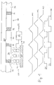
- the incremental wave transmitter 100 has as essential components a scanning unit 22 arranged on a first object 10 with a plurality of sensors C1, C2, C3, which is connected to an evaluation unit 60.
- the sensors C1, C2, C3 of the scanning unit 22 are used for scanning a graduation track 30, which is arranged on a second object 20.
- the graduation track 30 consists essentially of periodically alternately arranged first regions 32 and second regions 34. These each have different physical properties, whereby the scanning of the sensors C1, C2, C3 is possible.
- the first regions 32 may be electrically conductive metallic tabs and, accordingly, the second regions 34 may be holes or recesses in a sheet.
- the sensors C1, C2, C3 are then expedient inductive sensors, such as inductive proximity switches.
- Fig. 1 In the case of lateral relative movement of the first object 10 with respect to the second object 20 in the direction arranged by an arrow 24, the time profiles of the measurement signals M1, M2, M3 and the switching signals S1, S2 derived therefrom in the evaluation unit 60 are obtained Fig. 1 are shown schematically.
- the signal M1 belongs to the sensor C1, the signal M2 to the sensor C2 and the signal M3 to the sensor C3.
- the measurement signal is maximum, if the corresponding sensor, immediately before a conductive first region 32, the damping of the proximity switch, that is maximum.
- the measurement signals M1, M2, M3 have a phase offset of 120 ° over the period of the graduation track 30 due to the arrangement of the sensors C1, C2, C3.
- switching signals S1 and S2 are obtained in the evaluation unit 60 by a logical evaluation, which switches the signal S1 to HIGH, when the maximum measurement signal is supplied either from the sensor C1 or C2 and is otherwise switched to LOW. Furthermore, the signal S2 is switched to HIGH when the maximum signal is supplied from one of the sensors C2 or C3, but otherwise switched to LOW. Accordingly, in this embodiment, the sensor C2 is part of both the first and second subset of sensors.
- the relative velocity in one direction can be used to determine the speed of this displacement and, if a suitable start signal is present, also the absolute value of the displacement.
- information about the direction can be seen from the relative phase angle of the signals S1 and S2, can be obtained from the chronological sequence of these switching signals.
- the evaluation unit 60 delivers a displacement signal x (t) for further use, for example in a process control.
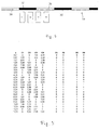
- FIG Fig. 2 A second exemplary embodiment of an incremental displacement sensor according to the invention is shown in FIG Fig. 2 shown.
- Equivalent components in all figures are given the same reference numerals as in FIG Fig. 1 Mistake.
- Fig. Are in the variant in Fig. 2 a total of four sensors C1, C2, C3 and C4 arranged along an extension direction 36 of the division track 30 over a period.
- the lateral extent, that is to say the extent in the extension direction 36, of the first regions 32 is here 1/4 of the period length p.
- the lateral extent of the second regions 34 is 3/4 of the period length p.
- the sensors C1, C2, C3 and C4 are as out Fig. 2 immediately apparent, arranged at a distance of 1/4 of the period length.
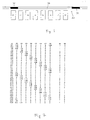
- the courses of the measuring signals of the sensors C1, C2, C3 and C4 and the switching signals S1 and S2 derived therefrom are tabulated in FIG Fig. 3 against a displacement x of the first object 10 relative to the second object 20. These courses correspond to those in Fig. 1 graphically represented signal curves.
- the logical switching condition here is that the switching signal S1 is switched to 1, if either the first sensor C1 or the second sensor C2 provides the maximum signal, but is otherwise set to 0.
- the switching signal S2 is set to 1 when the maximum signal is supplied from one of the sensors C2 or C3 and is otherwise 0.
- the values for the displacement x are in the table in FIG Fig. 3 just chosen so that the switching points are clarified.
- the switching conditions mentioned provide two switching signals S1 and S2 with a phase offset of 90 °.
- the further evaluation with regard to the location signal x (t) is then simple and it is possible to resort to known evaluation algorithms.
- FIGS. 4 and 5 A third embodiment of the incremental Weggebers invention is in connection with the FIGS. 4 and 5 described.
- Fig. 4 schematically shows the arrangement of a total of four sensors C1, C2, C3 and C4 along a division track 30.
- This embodiment corresponds essentially to the variant Fig. 3 , The only difference is that the lateral extent of the first regions 32 and the lateral extent of the second regions 34 of the graduation track 30 are each half of the period length p of the graduation track.
- This embodiment of the graduation track 30 makes it possible, in comparison to the evaluation according to the invention, to produce an alternative method of generating the switching signals necessary for position determination.
- the switching signals S3 and S4 are obtained by an alternative method, for which the sensors C1 and C3 are combined to a first sensor unit and the sensors C2 and C4 to a second sensor unit.
- the switching signal S3 is set to 1, when the sensor C1 compared to the sensor C3 delivers the larger measurement signal.
- FIGS. 6 and 7 A fourth exemplary embodiment of an incremental displacement sensor according to the invention is described in connection with FIGS FIGS. 6 and 7 explained.
- a total of eight sensors C1,..., C8 are arranged at intervals of 1/8 of the period length p over a period p of a graduation track.
- the division track is, as in the preceding examples, arranged on a second object, which is not shown separately here for reasons of clarity.
- the sensors are also, as in the preceding embodiments, part of a scanning unit which is arranged on a first object, which is likewise not shown here.
- the switching signal S2 is switched to 1 when the maximum measuring signal is supplied from one of the sensors C2, C3, C6 or C7. Accordingly, S2 is otherwise 0.
- the graduation track 30 can basically have any desired division ratio and that, independently of this, switching signals with a phase offset of 90 ° and in each case a duty ratio of 1: 1 are generated can be. This enables particularly diverse applications in the industrial sector.
- the present invention provides a novel incremental path sensor in which signal formation takes place by comparing sensor values, for example four individual sensors, which are arranged at a spacing of 1/4 of the period of a code rail or graduation track.
- the web-hole grid of the code rail need not be arranged in a 1: 1 ratio, but may also have other values, in particular 1: 4 or 1: 8. Evaluated in the invention described here, which sensors provide the maximum signal.
- the evaluation described here is as far as possible independent of distance, since it does not depend on the absolute measured values of the individual sensors.
- this method can be applied to any number of sensors per period.
- the accuracy of the displacement determination can be increased. For example, with eight sensors, as in the example of the FIGS. 6 and 7 represented, two pulses per period of the division track 30 are generated.
Abstract
Description
Die vorliegende Erfindung betrifft in einem ersten Aspekt einen Inkrementalweggeber nach dem Begriff des Anspruchs 1.The present invention relates, in a first aspect, to an incremental displacement sensor according to the term of
In einem weiteren Aspekt bezieht sich die Erfindung auf ein Verfahren zum Bestimmen einer Verschiebung eines ersten Objekts relativ zu einem zweiten Objekt.In a further aspect, the invention relates to a method for determining a displacement of a first object relative to a second object.
Ein gattungsgemäßer Inkrementalweggeber wird zum Bestimmen einer Verschiebung eines ersten Objekts relativ zu einem zweiten Objekt verwendet und ist beispielsweise aus
Bei einem gattungsgemäßen Verfahren, welches ebenfalls aus
Induktive Inkrementalweggeber sind außerdem in
Inkrementalweggeber werden zur Messung von Lageänderungen verwendet. Dabei bestimmen zwei zueinander versetzte Sensoren jeweils die Position einer Teilungsspur. Durch Zählen der Einzelimpulse kann die Bewegung der Teilungsspur relativ zu den Sensoren bestimmt werden. Da die von den beiden Sensoren erzeugten Signale einen Phasenversatz von beispielsweise 90° haben, ist außerdem eine Richtungserkennung möglich.Incremental encoders are used to measure changes in position. In this case, two mutually offset sensors each determine the position of a graduation track. By counting the individual pulses, the movement of the pitch track relative to the sensors can be determined. Since the signals generated by the two sensors have a phase offset of, for example 90 °, also a direction detection is possible.
Wenn bei dem Inkrementalweggeber induktive Sensoren eingesetzt werden, ergeben sich Schwierigkeiten aufgrund der Abhängigkeit des Schaltpunkts der Sensoren bei seitlicher Annäherung eines metallischen Objekts, beispielsweise eines leitenden Bereichs der Teilungsspur, von der Entfernung des Sensors zur Teilungsspur. Der leitende Bereich der Teilungsspur wird umso früher erkannt, je näher er sich vor dem Sensor befindet.When inductive sensors are used in the incremental pathfinder, difficulties arise due to the dependence of the switching point of the sensors on the lateral approach of a metallic object, such as a conductive portion of the pitch track, from the distance of the sensor to the pitch track. The conductive area of the pitch track is detected earlier the closer it is to the sensor.
Das für die Richtungserkennung gewünschte 1:1-Puls-Pausen-Verhältnis lässt sich so nur für einen ganz bestimmten Abstand erzielen.The desired 1: 1 pulse-pause ratio for the direction detection can only be achieved for a certain distance.
Weiterhin sind im Stand der Technik jeweils Teilungsspuren erforderlich, bei denen die ersten und die zweiten Bereiche jeweils dieselbe Ausdehnung haben. In der Praxis müssen deshalb Teilungsspuren in den meisten Fällen separat an den zu überwachenden Objekten angebracht werden, selbst wenn bereits sich wiederholende Strukturen, die grundsätzlich zum Erkennen einer Verschiebung geeignet wären, bereits vorhanden sind.Furthermore, divisional tracks are required in each case in the prior art, in which the first and the second regions each have the same extent. In practice, therefore, graduation marks must in most cases be applied separately to the objects to be monitored, even if already repetitive structures, which would be suitable in principle for detecting a shift already exist.
Aufgabe der Erfindung ist es, einen Inkrementalweggeber und ein Verfahren zum Bestimmen der Verschiebung eines ersten Objekts relativ zu einem zweiten Objekt zu schaffen, bei denen weitgehend unabhängig vom konkreten Abstand der eingesetzten Sensoren zu einer Teilungsspur zuverlässige Messresultate geliefert werden. The object of the invention is to provide an incremental displacement sensor and a method for determining the displacement of a first object relative to a second object, in which reliable measurement results are provided largely independently of the actual distance of the sensors used to a graduation track.
Diese Aufgabe wird in einem ersten Aspekt der Erfindung durch den Inkrementalweggeber des Anspruchs 1 gelöst.This object is achieved in a first aspect of the invention by the Inkrementalweggeber of
In einem weiteren Gesichtspunkt der Erfindung wird die Aufgabe durch das Verfahren mit den Merkmalen des Anspruchs 10 gelöst.In a further aspect of the invention, the object is achieved by the method having the features of
Vorteilhafte Weiterbildungen des erfindungsgemäßen Inkrementalweggebers sind Gegenstand der abhängigen Ansprüche.Advantageous developments of the incremental displacement sensor according to the invention are the subject of the dependent claims.
Der Inkrementalweggeber der oben genannten Art ist erfindungsgemäß dadurch weitergebildet, dass die Abtasteinheit mindestens drei Sensoren aufweist, die insbesondere entlang der Teilungsspur, über mindestens eine Periodenlänge verteilt voneinander beabstandet angeordnet sind, dass in der Auswerteeinheit zum Bestimmen der Verschiebung ein erstes Schaltsignal und ein zweites Schaltsignal aus den Messsignalen der Sensoren erzeugt wird, dass das erste Schaltsignal einen ersten Wert, insbesondere HIGH, annimmt, wenn derjenige Sensor, welcher ein maximales Messsignal ausgibt, zu einer ersten Untergruppe von Sensoren gehört, und ansonsten einen zweiten Wert, insbesondere LOW, annimmt, dass zweite Schaltsignal einen ersten Wert, insbesondere HIGH annimmt, wenn derjenige Sensor, welcher ein maximales Messsignal ausgibt, zu einer zweiten Untergruppe von Sensoren gehört, und ansonsten einen zweiten Wert, insbesondere LOW, annimmt, und wobei mindestens ein Sensor sowohl zur ersten Untergruppe als auch zur zweiten Untergruppe gehört.The Inkrementalweggeber of the above type according to the invention further developed in that the scanning unit has at least three sensors, in particular distributed along the pitch track, distributed over at least one period length spaced from each other, that in the evaluation unit for determining the shift, a first switching signal and a second switching signal is generated from the measurement signals of the sensors, that the first switching signal assumes a first value, in particular HIGH, if the sensor which outputs a maximum measuring signal belongs to a first subgroup of sensors, and otherwise assumes a second value, in particular LOW, in that the second switching signal assumes a first value, in particular HIGH, if the sensor which outputs a maximum measuring signal belongs to a second subgroup of sensors and otherwise assumes a second value, in particular LOW, and wherein at least one sensor is assigned both to the first subgroup e as well as the second subgroup.
Das Verfahren der oben genannten Art ist erfindungsgemäß dadurch weitergebildet, dass mindestens drei Sensoren entlang der Teilungsspur über mindestens eine Periodenlänge verteilt voneinander beabstandet angeordnet werden, dass die Verschiebung auf Grundlage eines ersten Schaltsignals und eines zweiten Schaltsignals bestimmt wird, dass das erste Schaltsignal einen ersten Wert, insbesondere HIGH, annimmt, wenn derjenige Sensor, welcher ein maximales Messsignal ausgibt, zu einer ersten Untergruppe von Sensoren gehört, und ansonsten einen zweiten Wert, insbesondere LOW, annimmt, dass zweite Schaltsignal einen ersten Wert, insbesondere HIGH, annimmt, wenn derjenige Sensor, welcher ein maximales Messsignal ausgibt, zu einer zweiten Untergruppe von Sensoren gehört, und ansonsten einen zweiten Wert, insbesondere LOW, annimmt, und wobei mindestens ein Sensor sowohl zur ersten Untergruppe als auch zur zweiten Untergruppe gehört.The method of the abovementioned type is developed according to the invention in that at least three sensors are arranged distributed along the pitch track distributed over at least one period length, that the shift is determined based on a first switching signal and a second switching signal that the first switching signal has a first value , in particular HIGH, assumes that the sensor which outputs a maximum measuring signal to a first subgroup heard from sensors, and otherwise a second value, in particular LOW, assumes that the second switching signal assumes a first value, in particular HIGH, if the sensor which outputs a maximum measurement signal belongs to a second subset of sensors, and otherwise a second value , in particular LOW, and wherein at least one sensor belongs to both the first subgroup and the second subgroup.
Als ein Kerngedanke der Erfindung kann angesehen werden, die Abstandsabhängigkeit der Sensorsignale auszuschalten durch eine logische Auswertung, bei der es nicht mehr auf die absolute Höhe der Messsignale, sondern nur noch auf die relative Höhe des jeweiligen Sensorsignals im Vergleich zu denjenigen der anderen Sensoren ankommt.As a core idea of the invention can be considered to turn off the distance dependence of the sensor signals by a logical evaluation in which it no longer depends on the absolute height of the measurement signals, but only on the relative height of the respective sensor signal compared to those of the other sensors.
Als zweiter Kerngedanke beinhaltet die Erfindung, damit zusammenhängend, mindestens drei Sensoren über eine Periode der Teilungsspur anzuordnen und eine Unterteilung dieser Sensoren in Untergruppen vorzunehmen, wobei mindestens ein Sensor Teil beider Untergruppen ist.As a second core idea, the invention, contiguous with it, involves arranging at least three sensors over a period of the graduation track and subdividing these sensors into subgroups, wherein at least one sensor is part of both subgroups.
Ein erster wesentlicher Vorteil der erfindungsgemäßen Lösung besteht in der Abstandsunabhängigkeit der Auswertung. Dies ermöglicht besonders vielfältige Einsatzmöglichkeiten im industriellen Bereich, da eine präzise Einrichtung der Messvorrichtung gegenüber der Teilungsspur nicht erforderlich ist.A first significant advantage of the solution according to the invention consists in the distance independence of the evaluation. This allows a particularly wide range of applications in the industrial sector, since a precise device of the measuring device with respect to the graduation track is not required.
Ein zweiter wesentlicher Vorteil kann darin gesehen werden, dass die Teilungsspur, im grundlegenden Unterschied zu bekannten Lösungen, nicht eine 1:1-Teilung aufweisen muss. Im Grundsatz kann jede beliebige periodische Struktur zur Generierung des Inkrementalsignals genutzt werden.A second significant advantage can be seen in the fact that the division track, in fundamental difference to known solutions, does not have to have a 1: 1 division. In principle, any periodic structure can be used to generate the incremental signal.
Als maximales Messsignal soll hier dasjenige Messsignal verstanden werden, das bei maximaler Annäherung des entsprechenden ersten oder zweiten Bereichs an den fraglichen Sensor von eben diesem Sensor geliefert wird. Bezogen auf 0 kann dies betragsmäßig gegebenenfalls auch ein Minimalwert sein. Letzteres ist beispielsweise der Fall, wenn mit einem induktiven Sensor die Bewegung eines Metallblechs bestimmt wird, in welchem sich in periodischen aber vergleichsweise großen Abständen Löcher befinden. Wenn ein Sensor direkt vor dem Loch positioniert ist, sinkt die Bedämpfung ab auf einen Minimalwert, der jedoch, bezogen auf die Vollbedämpfung ein Maximalwert, nämlich ein Wert maximaler Abweichung, ist.The maximum measurement signal is to be understood here as the measurement signal which is supplied to the sensor in question at the maximum approximation of the corresponding first or second range from this same sensor. In terms of absolute value, this may possibly also be a minimum value. The latter is the case, for example, when the movement of a metal sheet is determined with an inductive sensor, in which holes are located at periodic but comparatively large distances. If a sensor is positioned directly in front of the hole, the damping drops down to a minimum value which, however, based on the full attenuation, is a maximum value, namely a value of maximum deviation.
Wesentlich für die Erfindung ist außerdem, dass die Signale von zwei benachbarten Sensoren sich innerhalb des gewünschten Erfassungsbereichs der Schiene überschneiden. Das bedeutet, dass der laterale Abstand von zwei benachbarten Sensoren im Verhältnis zur lateralen Ausdehnung des kleineren der beiden Bereiche der Teilungsspur so gewählt ist, dass jedenfalls vorübergehend beide Sensoren ein Nachweissignal aufgrund dieses Bereichs liefern.It is also essential for the invention that the signals from two adjacent sensors overlap within the desired detection range of the rail. This means that the lateral distance of two adjacent sensors in relation to the lateral extent of the smaller of the two regions of the graduation track is selected such that, in any case, temporarily both sensors supply a detection signal based on this region.
Hieraus folgt, dass die Stegbreite einer Fahne einer Teilungsspur eine gewisse Mindestbreite haben muss, so dass zumindest vorübergehend zwei benachbarte Sensoren ein Signal aufgrund dieser Fahne liefern. Die genannte Bedingung kann also einerseits durch eine gewisse Mindestbreite des ersten und/oder des zweiten Bereichs und andererseits durch einen gewissen lateralen Höchstabstand der Sensoren erfüllt werden.It follows that the web width of a flag of a division track must have a certain minimum width, so that at least temporarily two adjacent sensors provide a signal due to this flag. The said condition can therefore be met on the one hand by a certain minimum width of the first and / or the second region and on the other hand by a certain lateral maximum distance of the sensors.
Solange die obige Bedingung im Hinblick auf den Abstand der Sensoren erfüllt ist, können die Sensoren grundsätzlich beliebig über eine Periode der Teilungsspur oder auch über mehrere Perioden verteilt angeordnet sein. Prinzipiell sind hier auch variable Abstände der Sensoren voneinander möglich, wobei in bevorzugten Ausführungsvarianten die Sensoren jedoch gleichmäßig voneinander beabstandet angeordnet sind, da sich hierbei die Auswertung einfacher gestaltet.As long as the above condition is fulfilled with regard to the distance of the sensors, the sensors can basically be arranged arbitrarily distributed over a period of the graduation track or over several periods. In principle, variable distances of the sensors from each other are also possible, but in preferred embodiments, the sensors are arranged evenly spaced from one another, since in this case the evaluation is simpler.
Grundsätzlich könnte bereits mit zwei Sensoren pro Periode, wenn außerdem die Teilungsspur ein Verhältnis der ersten Bereiche zu den zweiten Bereichen von 1:1 aufweist, ein abstandsunabhängiges Signal generiert werden. Allerdings kann hierbei nur ein einziges Inkrementalsignal erzeugt werden und eine Bestimmung der Richtung der Verschiebung des ersten Objekts relativ zum zweiten Objekt ist nicht möglich.In principle, with two sensors per period, even if the graduation track has a ratio of the first ranges to the second ranges of 1: 1, a distance-independent signal could already be generated. However, in this case only a single incremental signal can be generated and a determination of the direction of the displacement of the first object relative to the second object is not possible.
Die Targetbreite, also beispielsweise die Breite oder laterale Ausdehnung des ersten Bereichs, kann auch größer werden als eine Lückenbreite, also eine laterale Ausdehnung des zweiten Bereichs. Dann muss gegebenenfalls statt des maximalen Signals, wie vorstehend erläutert, das Minimum des Signals als Kriterium herangezogen werden.The target width, that is, for example, the width or lateral extent of the first area, can also be greater than a gap width, that is, a lateral extent of the second area. Then, if necessary, instead of the maximum signal, as explained above, the minimum of the signal must be used as a criterion.
Die Schaltsignale können auch invertiert ausgegeben werden, das heißt, dass statt des Werts HIGH der Wert LOW ausgegeben wird und umgekehrt.The switching signals can also be output inverted, that is, the value LOW is output instead of the value HIGH and vice versa.
Prinzipiell kann jede beliebige physikalische Eigenschaft, die mit Sensoren bestimmt werden kann, zur Bildung der Teilungsspur dienen. Beispielsweise können die ersten und die zweiten Bereiche unterschiedliche magnetische, optische oder auch mechanische Eigenschaften aufweisen.In principle, any physical property that can be determined with sensors can be used to form the graduation track. For example, the first and the second regions may have different magnetic, optical or also mechanical properties.
Besonders zahlreiche Einsatzmöglichkeiten und besonders zuverlässig im Hinblick auf den Betrieb in industriellen Umgebungen sind Ausführungsvarianten der Erfindung, bei denen die ersten Bereiche elektrisch leitend und die zweiten Bereiche elektrisch isolierend sind und die Sensoren induktive Sensoren sind.Particularly numerous application possibilities and particularly reliable with regard to operation in industrial environments are variants of the invention in which the first regions are electrically conductive and the second regions are electrically insulating and the sensors are inductive sensors.
Zwei phasenversetzte abstandsunabhängige Signale können generiert werden, wenn die Abtasteinheit drei Sensoren aufweist, wobei die erste Untergruppe durch den ersten und den zweiten Sensor und die zweite Untergruppe durch den zweiten und den dritten Sensor gebildet ist. Hierbei kommt man sensorseitig mit einem Minimum an Komponenten aus.Two phase-offset distance-independent signals can be generated when the scanning unit has three sensors, wherein the first subgroup is formed by the first and the second sensor and the second subgroup by the second and the third sensor. On the sensor side, this requires a minimum of components.
Bei einer besonders bevorzugten Variante des erfindungsgemäßen Inkrementalweggebers weist die Abtasteinheit vier Sensoren auf und die erste Untergruppe ist durch den ersten und den zweiten Sensor und die zweite Untergruppe durch den zweiten und den dritten Sensor gebildet. Bei diesem Ausführungsbeispiel können zwei um 90° phasenversetzte Schaltsignale erhalten werden, und wenn außerdem die Teilungsspur ein 1:1-Teilungsverhältnis aufweist, kann auf bekannte Auswertealgorithmen zurückgegriffen werden. Hierzu werden die Sensoren in einem Abstand von 1/4 der Teilungsperiode angeordnet.In a particularly preferred variant of the incremental displacement sensor according to the invention, the scanning unit has four sensors and the first subgroup is formed by the first and the second sensor and the second subgroup by the second and the third sensor. In this embodiment, two 90 ° out of phase switching signals can be obtained, and in addition, if the division track has a 1: 1 division ratio, known evaluation algorithms can be used. For this purpose, the sensors are arranged at a distance of 1/4 of the pitch period.
Grundsätzlich können aber auch periodische Strukturen mit einem größeren Tast- oder Teilungsverhältnis abgefragt werden. Beispielsweise kann die Abtasteinheit acht Sensoren aufweisen und die erste Untergruppe kann durch den ersten, den zweiten sowie den fünften und den sechsten Sensor gebildet sein und die zweite Untergruppe durch den zweiten, den dritten sowie den sechsten und den siebten Sensor gebildet sein.In principle, however, it is also possible to interrogate periodic structures with a larger tactile or division ratio. For example, the scanning unit may comprise eight sensors and the first subgroup may be formed by the first, the second and the fifth and the sixth sensor and the second subgroup may be formed by the second, the third and the sixth and the seventh sensor.
Die numerische Bezeichnung der Sensoren soll hier so verstanden werden, dass beispielsweise bei in einer Reihe angeordneten Sensoren der Sensor ganz links als der erste der dann nach rechts sich anschließende als der zweite und beispielsweise der rechts außen liegende Sensor als der achte Sensor bezeichnet wird.The numerical designation of the sensors should be understood here so that, for example, arranged in a row sensors, the sensor on the left as the first then the right subsequent as the second and for example the right outside sensor is referred to as the eighth sensor.
Allgemein gilt aufgrund der vorstehenden Erläuterungen, dass, je größer das Teilungsverhältnis der periodischen Struktur ist, desto mehr Sensoren benötigt werden.Generally, from the above explanation, the larger the pitch ratio of the periodic structure, the more sensors are required.
Die Teilungsspur kann grundsätzlich aus einer beliebigen periodischen Struktur bestehen, die im Hinblick auf das Abtasten geeignete physikalische Eigenschaften aufweist. Beispielsweise kann an einer sich bewegenden oder zu überwachenden Vorrichtung ein bereits vorhandenes Lochgitter als Teilungsspur dienen.The division track can basically consist of any periodic structure which has suitable physical properties with regard to the scanning. For example, an already existing perforated grid can serve as a graduation track on a moving or monitored device.
Die Auswahl der Sensoren für die erste und die zweite Untergruppe, zur Bildung des ersten und zweiten Schaltsignals, kann, solange die Bedingung, dass die Untergruppen jeweils mindestens einen gemeinsamen Sensor beinhalten, grundsätzlich beliebig erfolgen.The selection of the sensors for the first and the second subgroup, for the formation of the first and second switching signal, can, as long as the condition that the subgroups in each case contain at least one common sensor, in principle be arbitrary.
Die Auswertung gestaltet sich jedoch einfacher, wenn die erste Untergruppe und die zweite Untergruppe dieselbe Anzahl von Sensoren beinhalten.However, the evaluation is easier if the first subgroup and the second subset contain the same number of sensors.
Um Schaltsignale mit einem Tastverhältnis von 1:1 zu erhalten, ist außerdem bevorzugt, wenn die erste und die zweite Untergruppe jeweils die Hälfte aller Sensoren beinhalten. Dies bedeutet außerdem, dass die Anzahl der Sensoren geradzahlig ist.In order to obtain switching signals with a duty ratio of 1: 1, it is also preferred if the first and the second subgroup each contain half of all sensors. This also means that the number of sensors is even.
Weitere Vorteile und Merkmale der Erfindung werden nachstehend auf die beigefügten schematischen Figuren erläutert.Further advantages and features of the invention are explained below on the accompanying schematic figures.
Hierin zeigt:
- Fig. 1
- ein erstes Ausführungsbeispiel des erfindungsgemäßen Inkrementalweggebers mit drei Sensoren;
- Fig. 2
- ein zweites Ausführungsbeispiel des erfindungsgemäßen Inkrementalweggebers mit vier Sensoren;
- Fig. 3
- in tabellarischer Form dargestellte Messsignale und Schaltsignale aufgetragen gegen eine Verschiebung des ersten Objekts relativ zum zweiten Objekt für das Ausführungsbeispiel aus
Fig. 2 ; - Fig. 4
- ein drittes Ausführungsbeispiel des erfindungsgemäßen Inkrementalweggebers mit vier Sensoren;
- Fig. 5
- in tabellarischer Form dargestellte Messsignale und Schaltsignale aufgetragen gegen eine Verschiebung des ersten Objekts relativ zum zweiten Objekt für das Ausführungsbeispiel in
Fig. 4 ; - Fig. 6
- ein viertes Ausführungsbeispiel des erfindungsgemäßen Inkrementalweggebers mit acht Sensoren; und
- Fig. 7
- in tabellarischer Form dargestellte Messsignale und Schaltsignale gegen eine Verschiebung des ersten Objekts relativ zum zweiten Objekt für das Ausführungsbeispiel aus
Fig. 6 .
- Fig. 1
- a first embodiment of the incremental Weggebers invention with three sensors;
- Fig. 2
- a second embodiment of the incremental Weggebers invention with four sensors;
- Fig. 3
- in tabular form shown measurement signals and switching signals plotted against a displacement of the first object relative to the second object for the embodiment of
Fig. 2 ; - Fig. 4
- a third embodiment of the incremental Weggebers invention with four sensors;
- Fig. 5
- shown in tabular form measuring signals and switching signals plotted against a displacement of the first object relative to the second object for the embodiment in
Fig. 4 ; - Fig. 6
- A fourth embodiment of the incremental Weggebers invention with eight sensors; and
- Fig. 7
- shown in tabular form measuring signals and switching signals against a displacement of the first object relative to the second object for the embodiment of
Fig. 6 ,
Ein erstes Ausführungsbeispiel des erfindungsgemäßen Inkrementalweggebers wird mit Bezug auf
Der dort dargestellte erfindungsgemäße Inkrementalweggeber 100 weist als wesentliche Komponenten eine an einem ersten Objekt 10 angeordnete Abtasteinheit 22 mit einer Mehrzahl von Sensoren C1, C2, C3 auf, die mit einer Auswerteeinheit 60 verbunden ist.The incremental wave transmitter 100 according to the invention shown there has as essential components a
Die Sensoren C1, C2, C3 der Abtasteinheit 22 dienen zum Abtasten einer Teilungsspur 30, die an einem zweiten Objekt 20 angeordnet ist. Die Teilungsspur 30 besteht im Wesentlichen aus periodisch abwechselnd angeordneten ersten Bereichen 32 und zweiten Bereichen 34. Diese weisen jeweils unterschiedliche physikalische Eigenschaften auf, wodurch das Abtasten der Sensoren C1, C2, C3 möglich wird. Beispielsweise kann es sich bei den ersten Bereichen 32 um elektrisch leitende metallische Fahnen handeln und entsprechend können die zweiten Bereiche 34 Löcher oder Aussparungen in einem Blech sein. Die Sensoren C1, C2, C3 sind dann zweckmäßig induktive Sensoren, beispielsweise induktive Näherungsschalter.The sensors C1, C2, C3 of the
Bei seitlicher Relativbewegung des ersten Objekts 10 bezüglich des zweiten Objekts 20 in der durch einen Pfeil 24 angeordneten Richtung erhält man die zeitlichen Verläufe der Messsignale M1, M2, M3 und der daraus in der Auswerteeinheit 60 abgeleiteten Schaltsignale S1, S2, die im unteren Bereich von
Das Signal M1 gehört dabei zum Sensor C1, das Signal M2 zum Sensor C2 sowie das Signal M3 zum Sensor C3. Wie aus den Signalverläufen ersichtlich, wird das Messsignal jeweils maximal, wenn der entsprechende Sensor, unmittelbar vor einem leitenden ersten Bereich 32 steht, die Bedämpfung des Näherungsschalters, also maximal ist. Weiterhin ist aus den Verläufen ersichtlich, dass die Messsignale M1, M2, M3 aufgrund der Anordnung der Sensoren C1, C2, C3 verteilt über die Periode der Teilungsspur 30 einen Phasenversatz von 120° aufweisen.The signal M1 belongs to the sensor C1, the signal M2 to the sensor C2 and the signal M3 to the sensor C3. As can be seen from the waveforms, the measurement signal is maximum, if the corresponding sensor, immediately before a conductive
Die im unteren Bereich von
Aus jedem einzelnen der Schaltsignale S1 kann bei Relativbewegung in eine Richtung die Geschwindigkeit dieser Verschiebung und, wenn ein geeignetes Startsignal vorhanden ist, auch der Absolutbetrag der Verschiebung bestimmt werden. Bei beliebiger Richtung der Relativverschiebung kann eine Information über die Richtung, wie aus der relativen Phasenlage der Signale S1 und S2 ersichtlich, aus der zeitlichen Abfolge dieser Schaltsignale gewonnen werden. Insgesamt liefert die Auswerteeinheit 60 ein Verschiebungssignal x(t) zur weiteren Verwendung, beispielsweise bei einer Prozesssteuerung.From each individual one of the switching signals S1, the relative velocity in one direction can be used to determine the speed of this displacement and, if a suitable start signal is present, also the absolute value of the displacement. In any direction of the relative displacement, information about the direction, as can be seen from the relative phase angle of the signals S1 and S2, can be obtained from the chronological sequence of these switching signals. Overall, the
Ein zweites Ausführungsbeispiel eines erfindungsgemäßen Inkrementalweggebers ist in
Die Verläufe der Messsignale der Sensoren C1, C2, C3 und C4 und die daraus abgeleiteten Schaltsignale S1 und S2 sind tabellarisch in
Ein drittes Ausführungsbeispiel des erfindungsgemäßen Inkrementalweggebers wird im Zusammenhang mit den
Diese Ausbildung der Teilungsspur 30 ermöglicht im Vergleich zur erfindungsgemäßen Auswertung eine alternative Methode, die zur Ortsbestimmung nötigen Schaltsignale zu erzeugen. Dies wird mit Bezug auf
Die Schaltsignale S3 und S4 werden durch eine alternative Methode gewonnen, für welche die Sensoren C1 und C3 zu einer ersten Sensoreinheit und die Sensoren C2 und C4 zu einer zweiten Sensoreinheit zusammengefasst werden.The switching signals S3 and S4 are obtained by an alternative method, for which the sensors C1 and C3 are combined to a first sensor unit and the sensors C2 and C4 to a second sensor unit.
Die Auswertung erfolgt nun so, dass das Schaltsignal S3 auf 1 gestellt wird, wenn der Sensor C1 im Vergleich zum Sensor C3 das größere Messsignal liefert. Dies ist, wie aus der Tabelle in
Ein viertes Ausführungsbeispiel eines erfindungsgemäßen Inkrementalweggebers wird in Zusammenhang mit den
Für eine solche Anordnung von Sensoren erhaltene Verläufe der Messsignale sind in der Tabelle in
Andererseits wird das Schaltsignal S2 auf 1 geschaltet, wenn das maximale Messsignal von einem der Sensoren C2, C3, C6 oder C7 geliefert wird. Entsprechend ist S2 ansonsten 0.On the other hand, the switching signal S2 is switched to 1 when the maximum measuring signal is supplied from one of the sensors C2, C3, C6 or C7. Accordingly, S2 is otherwise 0.
Mit dem Ausführungsbeispiel der
Mit der vorliegenden Erfindung wird ein neuartiger Inkrementalweggeber bereitgestellt, bei dem eine Signalbildung durch einen Vergleich von Sensorwerten, beispielsweise von vier Einzelsensoren erfolgt, die in einem Abstand von 1/4 der Periode einer Codeschiene oder Teilungsspur angeordnet sind.The present invention provides a novel incremental path sensor in which signal formation takes place by comparing sensor values, for example four individual sensors, which are arranged at a spacing of 1/4 of the period of a code rail or graduation track.
Im wesentlichen Unterschied zu bisherigen Verfahren muss das Steg-Loch-Raster der Codeschiene nicht in einem 1:1-Verhältnis angeordnet werden, sondern kann auch andere Werte, insbesondere 1:4 oder 1:8 aufweisen. Ausgewertet wird bei der hier beschriebenen Erfindung, welche Sensoren das maximale Signal liefern.In substantial contrast to previous methods, the web-hole grid of the code rail need not be arranged in a 1: 1 ratio, but may also have other values, in particular 1: 4 or 1: 8. Evaluated in the invention described here, which sensors provide the maximum signal.
Aufgrund der Auswertung der Maxima ist die hier beschriebene Auswertung weitestgehend abstandsunabhängig, da nicht von den absoluten Messwerten der Einzelsensoren abhängig.Due to the evaluation of the maxima, the evaluation described here is as far as possible independent of distance, since it does not depend on the absolute measured values of the individual sensors.
Grundsätzlich kann dieses Verfahren für eine beliebige Anzahl von Sensoren pro Periode angewendet werden. Durch eine höhere Anzahl von Sensoren pro Periode kann im Grundsatz außerdem die Genauigkeit der Verschiebungsbestimmung erhöht werden. Beispielsweise können mit acht Sensoren, wie im Beispiel aus den
Claims (10)
mit einer mit dem ersten Objekt (10) verbundenen oder zu verbindenden Abtasteinheit (22) zum Abtasten einer mit dem zweiten Objekt (20) verbundenen oder zu verbindenden Teilungsspur (30) mit ersten Bereichen (32) und zweiten Bereichen (34), die mit einer Periodenlänge (p) abwechselnd angeordnet sind,
wobei die ersten Bereiche (32) eine erste physikalische Eigenschaft und die zweiten Bereiche (34) eine davon unterschiedliche zweite physikalische Eigenschaft aufweisen, und
wobei die Abtasteinheit (22) eine Mehrzahl von Sensoren (C1,..,C8) zum Abtasten der ersten Bereiche (32) und der zweiten Bereiche (34) aufgrund der ersten und/oder der zweiten physikalischen Eigenschaft aufweist, und mit einer mit der Abtasteinheit (22) verbundenen Auswerteeinheit (60) zum Bestimmen der Verschiebung (x) auf Grundlage von Messsignalen der Sensoren (C1,..,C8),
dadurch gekennzeichnet,
dass die Abtasteinheit (22) mindestens drei Sensoren (C1,..,C8) aufweist, über mindestens eine Periodenlänge (p) verteilt voneinander beabstandet angeordnet sind,
dass in der Auswerteeinheit (60) zum Bestimmen der Verschiebung (x) ein erstes Schaltsignal (S1) und ein zweites Schaltsignal (S2) aus den Messsignalen der Sensoren (C1,..,C8) generierbar ist,
dass das erste Schaltsignal (S1) einen ersten Wert, insbesondere HIGH, annimmt, wenn derjenige Sensor (C1,..,C8), welcher ein maximales Messsignal ausgibt, zu einer ersten Untergruppe von Sensoren (C1,..,C8) gehört, und ansonsten einen zweiten Wert, insbesondere LOW, annimmt,
dass zweite Schaltsignal (S1) einen ersten Wert, insbesondere HIGH annimmt, wenn derjenige Sensor (C1,..,C8), welcher ein maximales Messsignal ausgibt, zu einer zweiten Untergruppe von Sensoren (C1,..,C8) gehört, und ansonsten einen zweiten Wert, insbesondere LOW, annimmt,
und
wobei mindestens ein Sensor (C1,..,C8) sowohl zur ersten Untergruppe als auch zur zweiten Untergruppe gehört.Incremental Weggeber for determining a displacement of a first object (10) relative to a second object (20), in particular for performing the method according to claim 12,
with a scanning unit (22) connected or to be connected to the first object (10) for scanning a graduation track (30) connected to the second object (20) and having first areas (32) and second areas (34) a period length (p) are arranged alternately,
wherein the first regions (32) have a first physical property and the second regions (34) have a different second physical property, and
wherein the scanning unit (22) has a plurality of sensors (C1, .., C8) for scanning the first regions (32) and the second regions (34) based on the first and / or the second physical property, and one with the Scanning unit (22) connected to the evaluation unit (60) for determining the displacement (x) on the basis of measurement signals of the sensors (C1, .., C8),
characterized,
in that the scanning unit (22) has at least three sensors (C1,..., C8) distributed over at least one period length (p) at a distance from one another,
in that in the evaluation unit (60) for determining the displacement (x) a first switching signal (S1) and a second switching signal (S2) can be generated from the measuring signals of the sensors (C1, .., C8),
that the first switching signal (S1) assuming a first value, in particular HIGH if the particular sensor (C1, .., C8) having the maximum measured signal belongs to a first subset of sensors (C1, .., C8), and otherwise assumes a second value, in particular LOW,
that the second switching signal (S1) assumes a first value, in particular HIGH, if the sensor (C1, .., C8) which outputs a maximum measuring signal belongs to a second subgroup of sensors (C1, .., C8), and otherwise assumes a second value, in particular LOW,
and
wherein at least one sensor (C1, .., C8) belongs to both the first subgroup and the second subgroup.
dadurch gekennzeichnet,
dass die Sensoren (C1,..,C8) gleichmäßig voneinander beabstandet angeordnet sind.Incremental transducer according to claim 1,
characterized,
that the sensors (C1, .., C8) are arranged evenly spaced from each other.
dadurch gekennzeichnet,
dass die ersten Bereiche (32) elektrisch leitend und die zweiten Bereiche (34) elektrisch isolierend sind und
dass die Sensoren (C1,..,C8) induktive Sensoren (C1,..,C8) sind.Incremental transducer according to one of claims 1 or 2,
characterized,
that the first regions (32) are electrically conductive and the second regions (34) are electrically insulating, and
that the sensors (C1, .., C8) inductive sensors (C1, .., C8) are.
dadurch gekennzeichnet,
dass die Abtasteinheit (22) drei Sensoren (C1, C2, C3) aufweist,
dass die erste Untergruppe durch den ersten und den zweiten Sensor (C1) gebildet ist und
dass die zweite Untergruppe durch den zweiten und den dritten Sensor (C2, C3) gebildet ist.Incremental transducer according to one of claims 1 to 3,
characterized,
in that the scanning unit (22) has three sensors (C1, C2, C3),
that the first sub-group by the first and the second sensor (C1) is formed and
that the second subset through the second and third sensors (C2, C3) is formed.
dadurch gekennzeichnet,
dass die Abtasteinheit (22) vier Sensoren (C1,..,C4) aufweist, und
dass die erste Untergruppe durch den ersten und den zweiten Sensor (C1, C2) gebildet ist und
dass die zweite Untergruppe durch den zweiten und den dritten Sensor (C3, C4) gebildet ist.Incremental transducer according to one of claims 1 to 3,
characterized,
that the scanning unit (22) has four sensors (C1, .., C4), and
that the first sub-group by the first and the second sensor (C1, C2) is formed and
that the second sub-group by the second and the third sensor (C3, C4) is formed.
dadurch gekennzeichnet,
dass die Abtasteinheit (22) acht Sensoren (C1,..,C8) aufweist und dass die erste Untergruppe (C1, C2, C5, C6) durch den ersten, den zweiten sowie den fünften und den sechsten Sensor gebildet ist und
dass die zweite Untergruppe (C2, C3, C6, C7) durch den zweiten, den dritten sowie den sechsten und den siebten Sensor gebildet ist.Incremental transducer according to one of claims 1 to 3,
characterized,
that the scanning unit (22) has eight sensors (C1, .., C8) and that the first subgroup (C1, C2, C5, C6) is formed by the first, the second and the fifth and the sixth sensor, and
that the second sub-group (C2, C3, C6, C7) by the second, the third and the sixth and seventh sensor is formed.
dadurch gekennzeichnet,
dass die Teilungsspur (30) durch ein Lochgitter gebildet ist.Incremental transducer according to one of claims 1 to 6,
characterized,
that the division track (30) is formed by a grid of holes.
dadurch gekennzeichnet,
dass die erste Untergruppe und die zweite Untergruppe dieselbe Anzahl von Sensoren (C1,..,C8) beinhalten.Incremental transducer according to one of claims 1 to 7,
characterized,
that the first subset and the second subset of the same number of sensors (C1, .., C8) include.
dadurch gekennzeichnet,
dass die erste Untergruppe und die zweite Untergruppe jeweils die Hälfte aller Sensoren (C1,..,C8) beinhalten.Incremental transducer according to one of claims 1 to 8,
characterized,
that the first subset and the second subset each contain half of the sensors (C1, .., C8).
insbesondere unter Verwendung eines Inkrementalweggebers nach einem Ansprüche 1 bis 9,
bei dem eine mit dem ersten Objekt (10) verbundene Teilungsspur (30) mit einer Mehrzahl von Sensoren (C1,..,C8), die mit dem zweiten Objekt (20) verbunden sind, abgetastet wird,
wobei die Teilungsspur (30) erste Bereiche (32) mit einer ersten physikalischen Eigenschaft und zweite Bereiche (34) mit einer zweiten physikalischen Eigenschaft aufweist, die mit einer Periodenlänge (p) abwechselnd angeordnet sind, und
bei dem die Verschiebung des ersten Objekts relativ zu dem zweiten Objekt aus Messsignalen der Sensoren (C1,..,C8), die aufgrund der ersten und/oder der zweiten physikalischen Eigenschaft gewonnen werden, bestimmt wird,
dadurch gekennzeichnet,
dass mindestens drei Sensoren (C1,..,C8) entlang der Teilungsspur (30) über mindestens eine Periodenlänge (p) verteilt voneinander beabstandet angeordnet werden,
dass die Verschiebung auf Grundlage eines ersten Schaltsignals und eines zweiten Schaltsignals bestimmt wird,
dass das erste Schaltsignal (S1) einen ersten Wert, insbesondere HIGH, annimmt, wenn derjenige Sensor (C1,..,C8), welcher ein maximales Messsignal ausgibt, zu einer ersten Untergruppe von Sensoren (C1,..,C8) gehört, und ansonsten einen zweiten Wert, insbesondere LOW, annimmt,
dass zweite Schaltsignal (S1) einen ersten Wert, insbesondere HIGH, annimmt, wenn derjenige Sensor (C1,..,C8), welcher ein maximales Messsignal ausgibt, zu einer zweiten Untergruppe von Sensoren (C1,..,C8) gehört, und ansonsten einen zweiten Wert, insbesondere LOW, annimmt,
und
wobei mindestens ein Sensor (C1,..,C8) sowohl zur ersten Untergruppe als auch zur zweiten Untergruppe gehört.Method for determining a displacement of a first object relative to a second object,
in particular using an incremental displacement sensor according to one of claims 1 to 9,
wherein a division track (30) connected to the first object (10) is scanned with a plurality of sensors (C1, .., C8) connected to the second object (20),
wherein the graduation track (30) comprises first regions (32) having a first physical property and second regions (34) having a second physical property which are arranged alternately with a period length (p), and
in which the displacement of the first object relative to the second object is determined from measurement signals of the sensors (C1,..., C8) which are obtained on the basis of the first and / or the second physical property,
characterized,
that at least three sensors (C1, .., C8) along the graduation track (30) over at least one period length (p) are distributed spaced from one another,
that the shift is determined based on a first switching signal and a second switching signal,
that the first switching signal (S1) assuming a first value, in particular HIGH if the particular sensor (C1, .., C8), which outputs a maximum measuring signal, (C8 C1, ..) belonging to a first group of sensors, and otherwise assumes a second value, in particular LOW,
that the second switching signal (S1) assumes a first value, in particular HIGH, if the sensor (C1, .., C8) which outputs a maximum measuring signal belongs to a second subgroup of sensors (C1, .., C8), and otherwise assumes a second value, in particular LOW,
and
wherein at least one sensor (C1, .., C8) belongs to both the first subgroup and the second subgroup.
Applications Claiming Priority (1)
| Application Number | Priority Date | Filing Date | Title |
|---|---|---|---|
| DE102007022942A DE102007022942A1 (en) | 2007-05-16 | 2007-05-16 | An incremental pathfinder and method for determining a displacement of a first object relative to a second object |
Publications (3)
| Publication Number | Publication Date |
|---|---|
| EP1992914A2 true EP1992914A2 (en) | 2008-11-19 |
| EP1992914A3 EP1992914A3 (en) | 2011-06-29 |
| EP1992914B1 EP1992914B1 (en) | 2012-05-09 |
Family
ID=39666182
Family Applications (1)
| Application Number | Title | Priority Date | Filing Date |
|---|---|---|---|
| EP08009021A Active EP1992914B1 (en) | 2007-05-16 | 2008-05-15 | Incremental displacement sensor and method for determining the displacement of an object relative to another object |
Country Status (3)
| Country | Link |
|---|---|
| US (1) | US7535216B2 (en) |
| EP (1) | EP1992914B1 (en) |
| DE (1) | DE102007022942A1 (en) |
Cited By (1)
| Publication number | Priority date | Publication date | Assignee | Title |
|---|---|---|---|---|
| EP2072960A3 (en) * | 2007-12-21 | 2012-05-02 | Pepperl + Fuchs GmbH | Incremental displacement sensor and method for determining the displacement of an object relative to another object |
Families Citing this family (2)
| Publication number | Priority date | Publication date | Assignee | Title |
|---|---|---|---|---|
| DE102016002487B3 (en) * | 2016-03-03 | 2017-08-03 | Tdk-Micronas Gmbh | Positioning sensor unit |
| DE102016005826B4 (en) | 2016-05-17 | 2020-07-16 | Pepperl+Fuchs Ag | Position measuring unit and position measuring method |
Citations (9)
| Publication number | Priority date | Publication date | Assignee | Title |
|---|---|---|---|---|
| DE3100486A1 (en) | 1980-01-10 | 1982-02-18 | Centro Ricerche Fiat S.p.A., 10043 Orbassano, Torino | DEVICE FOR DETERMINING THE POSITION OF A WELDING MACHINE FOR AUTOMATIC ARC WELDING |
| US4893078A (en) | 1987-05-28 | 1990-01-09 | Auchterlonie Richard C | Absolute position sensing using sets of windings of different pitches providing respective indications of phase proportional to displacement |
| US5003260A (en) | 1987-05-28 | 1991-03-26 | Auchterlonie Richard C | Inductive position sensor having plural phase windings on a support and a displaceable phase sensing element returning a phase indicating signal by electromagnetic induction to eliminate wire connections |
| EP0473808A1 (en) | 1990-09-03 | 1992-03-11 | Hottinger Baldwin Messtechnik Gmbh | Measuring device for the determination of a path or a position |
| EP0446969B1 (en) | 1984-02-10 | 1996-12-11 | Kabushiki Kaisha Sg | Linear position detection device |
| DE19701319A1 (en) | 1997-01-16 | 1998-07-23 | Heidenhain Gmbh Dr Johannes | Position-measuring unit with scale rule having at least one gauge |
| EP0795738B1 (en) | 1996-03-16 | 2001-10-24 | Atsutoshi Goto | Induction-type linear position detector device |
| US6552666B1 (en) | 1996-03-16 | 2003-04-22 | Atsutoshi Goto | Phase difference detection device and method for a position detector |
| EP1071927B1 (en) | 1998-04-16 | 2003-09-24 | Jean-Pierre Bazenet | Device for incremental measurement of position |
Family Cites Families (4)
| Publication number | Priority date | Publication date | Assignee | Title |
|---|---|---|---|---|
| DE4318386C2 (en) * | 1993-06-01 | 2002-09-19 | Rohm Co Ltd | Optical encoder device for detecting the movement of a movable element |
| DE19637855A1 (en) * | 1996-09-17 | 1998-03-19 | Teves Gmbh Alfred | System for identifying movement direction, esp. direction of rotation of vehicle steering-wheel |
| DE19717364C1 (en) * | 1997-04-24 | 1998-08-27 | Siemens Ag | Method for identifying direction of rotation of wheel using Hall effect probes |
| DE19963809C2 (en) * | 1999-12-30 | 2002-01-17 | Osram Opto Semiconductors Gmbh | Optical encoder with triple photodiode |
-
2007
- 2007-05-16 DE DE102007022942A patent/DE102007022942A1/en not_active Ceased
-
2008
- 2008-05-15 EP EP08009021A patent/EP1992914B1/en active Active
- 2008-05-15 US US12/120,772 patent/US7535216B2/en active Active
Patent Citations (10)
| Publication number | Priority date | Publication date | Assignee | Title |
|---|---|---|---|---|
| DE3100486A1 (en) | 1980-01-10 | 1982-02-18 | Centro Ricerche Fiat S.p.A., 10043 Orbassano, Torino | DEVICE FOR DETERMINING THE POSITION OF A WELDING MACHINE FOR AUTOMATIC ARC WELDING |
| EP0446969B1 (en) | 1984-02-10 | 1996-12-11 | Kabushiki Kaisha Sg | Linear position detection device |
| US4893078A (en) | 1987-05-28 | 1990-01-09 | Auchterlonie Richard C | Absolute position sensing using sets of windings of different pitches providing respective indications of phase proportional to displacement |
| US5003260A (en) | 1987-05-28 | 1991-03-26 | Auchterlonie Richard C | Inductive position sensor having plural phase windings on a support and a displaceable phase sensing element returning a phase indicating signal by electromagnetic induction to eliminate wire connections |
| EP0473808A1 (en) | 1990-09-03 | 1992-03-11 | Hottinger Baldwin Messtechnik Gmbh | Measuring device for the determination of a path or a position |
| EP0795738B1 (en) | 1996-03-16 | 2001-10-24 | Atsutoshi Goto | Induction-type linear position detector device |
| US6552666B1 (en) | 1996-03-16 | 2003-04-22 | Atsutoshi Goto | Phase difference detection device and method for a position detector |
| US6885310B2 (en) | 1996-03-16 | 2005-04-26 | Atsutoshi Goto | Phase difference detection device and method for a position detector |
| DE19701319A1 (en) | 1997-01-16 | 1998-07-23 | Heidenhain Gmbh Dr Johannes | Position-measuring unit with scale rule having at least one gauge |
| EP1071927B1 (en) | 1998-04-16 | 2003-09-24 | Jean-Pierre Bazenet | Device for incremental measurement of position |
Cited By (1)
| Publication number | Priority date | Publication date | Assignee | Title |
|---|---|---|---|---|
| EP2072960A3 (en) * | 2007-12-21 | 2012-05-02 | Pepperl + Fuchs GmbH | Incremental displacement sensor and method for determining the displacement of an object relative to another object |
Also Published As
| Publication number | Publication date |
|---|---|
| EP1992914B1 (en) | 2012-05-09 |
| US7535216B2 (en) | 2009-05-19 |
| US20080284417A1 (en) | 2008-11-20 |
| DE102007022942A1 (en) | 2008-11-20 |
| EP1992914A3 (en) | 2011-06-29 |
Similar Documents
| Publication | Publication Date | Title |
|---|---|---|
| EP2502030B1 (en) | Inductive measuring device for detecting lengths and angles | |
| EP0848804B1 (en) | Steering-angle sensor giving absolute values | |
| EP1649250B2 (en) | Device and method for recording the path of a target object | |
| EP2183550B2 (en) | Inductive displacement sensor, coding device, and method for determining a position of a first object relative to a second object | |
| EP3040688B1 (en) | Capacitive linear encoder | |
| EP2126517B1 (en) | Inductive incremental displacement transmitter and method for determining the displacement of a first object relative to a second object | |
| EP1770373A1 (en) | Absolute position measuring device | |
| EP0461300B1 (en) | Method for measuring a length and electronic slide gauge | |
| DE102006048628A1 (en) | Measuring element with a track acting as a material measure and corresponding, with such a measuring element executable measuring method | |
| EP1992914B1 (en) | Incremental displacement sensor and method for determining the displacement of an object relative to another object | |
| EP2869031B1 (en) | Position measuring device | |
| DE10162849B4 (en) | Length measuring system in which a scale is moved relative to the position of spaced length sensors | |
| EP2072960B1 (en) | Incremental displacement sensor and method for determining the displacement of an object relative to another object | |
| EP2116814A1 (en) | Measuring device for calculating a position and/or a speed | |
| DE102020205398A1 (en) | Inductive position measuring device | |
| DE10124761A1 (en) | Method for contactless, linear position measurement | |
| DE102013226200A1 (en) | Absolute position measuring device | |
| EP4279874A1 (en) | Inductive position measurement device | |
| DE10158942B4 (en) | Device and method for detecting the position of a measuring object | |
| DE102004038904A1 (en) | Body and sensor unit relative movement direction determining method for motor vehicle, involves using motional direction determined based on code belonging to best suited unit pattern to recognize rotation direction in gear shifts | |
| EP1783462A1 (en) | Angle measuring device |
Legal Events
| Date | Code | Title | Description |
|---|---|---|---|
| PUAI | Public reference made under article 153(3) epc to a published international application that has entered the european phase |
Free format text: ORIGINAL CODE: 0009012 |
|
| AK | Designated contracting states |
Kind code of ref document: A2 Designated state(s): AT BE BG CH CY CZ DE DK EE ES FI FR GB GR HR HU IE IS IT LI LT LU LV MC MT NL NO PL PT RO SE SI SK TR |
|
| AX | Request for extension of the european patent |
Extension state: AL BA MK RS |
|
| PUAL | Search report despatched |
Free format text: ORIGINAL CODE: 0009013 |
|
| AK | Designated contracting states |
Kind code of ref document: A3 Designated state(s): AT BE BG CH CY CZ DE DK EE ES FI FR GB GR HR HU IE IS IT LI LT LU LV MC MT NL NO PL PT RO SE SI SK TR |
|
| AX | Request for extension of the european patent |
Extension state: AL BA MK RS |
|
| 17P | Request for examination filed |
Effective date: 20110629 |
|
| GRAP | Despatch of communication of intention to grant a patent |
Free format text: ORIGINAL CODE: EPIDOSNIGR1 |
|
| RAP1 | Party data changed (applicant data changed or rights of an application transferred) |
Owner name: PEPPERL + FUCHS GMBH |
|
| AKX | Designation fees paid |
Designated state(s): CH DE FR GB LI |
|
| GRAS | Grant fee paid |
Free format text: ORIGINAL CODE: EPIDOSNIGR3 |
|
| GRAA | (expected) grant |
Free format text: ORIGINAL CODE: 0009210 |
|
| AK | Designated contracting states |
Kind code of ref document: B1 Designated state(s): CH DE FR GB LI |
|
| REG | Reference to a national code |
Ref country code: GB Ref legal event code: FG4D Free format text: NOT ENGLISH |
|
| REG | Reference to a national code |
Ref country code: CH Ref legal event code: NV Representative=s name: BOGENSBERGER PATENT- & MARKENBUERO DR. BURKHARD BO Ref country code: CH Ref legal event code: EP |
|
| REG | Reference to a national code |
Ref country code: DE Ref legal event code: R096 Ref document number: 502008007162 Country of ref document: DE Effective date: 20120705 |
|
| PLBE | No opposition filed within time limit |
Free format text: ORIGINAL CODE: 0009261 |
|
| STAA | Information on the status of an ep patent application or granted ep patent |
Free format text: STATUS: NO OPPOSITION FILED WITHIN TIME LIMIT |
|
| 26N | No opposition filed |
Effective date: 20130212 |
|
| REG | Reference to a national code |
Ref country code: CH Ref legal event code: PCAR Free format text: NEW ADDRESS: FALLSGASSE 7, 9492 ESCHEN (LI) |
|
| REG | Reference to a national code |
Ref country code: DE Ref legal event code: R097 Ref document number: 502008007162 Country of ref document: DE Effective date: 20130212 |
|
| REG | Reference to a national code |
Ref country code: FR Ref legal event code: PLFP Year of fee payment: 9 |
|
| PGFP | Annual fee paid to national office [announced via postgrant information from national office to epo] |
Ref country code: GB Payment date: 20160407 Year of fee payment: 9 |
|
| REG | Reference to a national code |
Ref country code: FR Ref legal event code: PLFP Year of fee payment: 10 |
|
| GBPC | Gb: european patent ceased through non-payment of renewal fee |
Effective date: 20170515 |
|
| PG25 | Lapsed in a contracting state [announced via postgrant information from national office to epo] |
Ref country code: GB Free format text: LAPSE BECAUSE OF NON-PAYMENT OF DUE FEES Effective date: 20170515 |
|
| REG | Reference to a national code |
Ref country code: FR Ref legal event code: PLFP Year of fee payment: 11 |
|
| REG | Reference to a national code |
Ref country code: DE Ref legal event code: R082 Ref document number: 502008007162 Country of ref document: DE Representative=s name: SCHIFFER, AXEL, DIPL.-PHYS.UNIV. DR.RER.NAT., DE |
|
| PGFP | Annual fee paid to national office [announced via postgrant information from national office to epo] |
Ref country code: CH Payment date: 20180523 Year of fee payment: 11 |
|
| PGFP | Annual fee paid to national office [announced via postgrant information from national office to epo] |
Ref country code: FR Payment date: 20180522 Year of fee payment: 11 |
|
| REG | Reference to a national code |
Ref country code: CH Ref legal event code: PL |
|
| PG25 | Lapsed in a contracting state [announced via postgrant information from national office to epo] |
Ref country code: CH Free format text: LAPSE BECAUSE OF NON-PAYMENT OF DUE FEES Effective date: 20190531 Ref country code: LI Free format text: LAPSE BECAUSE OF NON-PAYMENT OF DUE FEES Effective date: 20190531 |
|
| PG25 | Lapsed in a contracting state [announced via postgrant information from national office to epo] |
Ref country code: FR Free format text: LAPSE BECAUSE OF NON-PAYMENT OF DUE FEES Effective date: 20190531 |
|
| PGFP | Annual fee paid to national office [announced via postgrant information from national office to epo] |
Ref country code: DE Payment date: 20230519 Year of fee payment: 16 |