EP1995273A2 - Process and apparatus for producing foamed styrenic polymers - Google Patents
Process and apparatus for producing foamed styrenic polymers Download PDFInfo
- Publication number
- EP1995273A2 EP1995273A2 EP08156742A EP08156742A EP1995273A2 EP 1995273 A2 EP1995273 A2 EP 1995273A2 EP 08156742 A EP08156742 A EP 08156742A EP 08156742 A EP08156742 A EP 08156742A EP 1995273 A2 EP1995273 A2 EP 1995273A2
- Authority
- EP
- European Patent Office
- Prior art keywords
- blowing agent
- styrenic polymer
- polymer composition
- extruder
- mixture
- Prior art date
- Legal status (The legal status is an assumption and is not a legal conclusion. Google has not performed a legal analysis and makes no representation as to the accuracy of the status listed.)
- Granted
Links
Images


Classifications
-
- C—CHEMISTRY; METALLURGY
- C08—ORGANIC MACROMOLECULAR COMPOUNDS; THEIR PREPARATION OR CHEMICAL WORKING-UP; COMPOSITIONS BASED THEREON
- C08J—WORKING-UP; GENERAL PROCESSES OF COMPOUNDING; AFTER-TREATMENT NOT COVERED BY SUBCLASSES C08B, C08C, C08F, C08G or C08H
- C08J9/00—Working-up of macromolecular substances to porous or cellular articles or materials; After-treatment thereof
- C08J9/04—Working-up of macromolecular substances to porous or cellular articles or materials; After-treatment thereof using blowing gases generated by a previously added blowing agent
- C08J9/12—Working-up of macromolecular substances to porous or cellular articles or materials; After-treatment thereof using blowing gases generated by a previously added blowing agent by a physical blowing agent
- C08J9/127—Mixtures of organic and inorganic blowing agents
-
- B—PERFORMING OPERATIONS; TRANSPORTING
- B29—WORKING OF PLASTICS; WORKING OF SUBSTANCES IN A PLASTIC STATE IN GENERAL
- B29C—SHAPING OR JOINING OF PLASTICS; SHAPING OF MATERIAL IN A PLASTIC STATE, NOT OTHERWISE PROVIDED FOR; AFTER-TREATMENT OF THE SHAPED PRODUCTS, e.g. REPAIRING
- B29C44/00—Shaping by internal pressure generated in the material, e.g. swelling or foaming ; Producing porous or cellular expanded plastics articles
- B29C44/20—Shaping by internal pressure generated in the material, e.g. swelling or foaming ; Producing porous or cellular expanded plastics articles for articles of indefinite length
- B29C44/26—Shaping by internal pressure generated in the material, e.g. swelling or foaming ; Producing porous or cellular expanded plastics articles for articles of indefinite length using several expanding steps
-
- B—PERFORMING OPERATIONS; TRANSPORTING
- B29—WORKING OF PLASTICS; WORKING OF SUBSTANCES IN A PLASTIC STATE IN GENERAL
- B29C—SHAPING OR JOINING OF PLASTICS; SHAPING OF MATERIAL IN A PLASTIC STATE, NOT OTHERWISE PROVIDED FOR; AFTER-TREATMENT OF THE SHAPED PRODUCTS, e.g. REPAIRING
- B29C44/00—Shaping by internal pressure generated in the material, e.g. swelling or foaming ; Producing porous or cellular expanded plastics articles
- B29C44/34—Auxiliary operations
- B29C44/3442—Mixing, kneading or conveying the foamable material
- B29C44/3446—Feeding the blowing agent
-
- B—PERFORMING OPERATIONS; TRANSPORTING
- B29—WORKING OF PLASTICS; WORKING OF SUBSTANCES IN A PLASTIC STATE IN GENERAL
- B29C—SHAPING OR JOINING OF PLASTICS; SHAPING OF MATERIAL IN A PLASTIC STATE, NOT OTHERWISE PROVIDED FOR; AFTER-TREATMENT OF THE SHAPED PRODUCTS, e.g. REPAIRING
- B29C44/00—Shaping by internal pressure generated in the material, e.g. swelling or foaming ; Producing porous or cellular expanded plastics articles
- B29C44/34—Auxiliary operations
- B29C44/3469—Cell or pore nucleation
- B29C44/348—Cell or pore nucleation by regulating the temperature and/or the pressure, e.g. suppression of foaming until the pressure is rapidly decreased
-
- B—PERFORMING OPERATIONS; TRANSPORTING
- B29—WORKING OF PLASTICS; WORKING OF SUBSTANCES IN A PLASTIC STATE IN GENERAL
- B29C—SHAPING OR JOINING OF PLASTICS; SHAPING OF MATERIAL IN A PLASTIC STATE, NOT OTHERWISE PROVIDED FOR; AFTER-TREATMENT OF THE SHAPED PRODUCTS, e.g. REPAIRING
- B29C44/00—Shaping by internal pressure generated in the material, e.g. swelling or foaming ; Producing porous or cellular expanded plastics articles
- B29C44/34—Auxiliary operations
- B29C44/60—Measuring, controlling or regulating
- B29C44/605—Calibration following a shaping operation, e.g. extrusion
-
- E—FIXED CONSTRUCTIONS
- E04—BUILDING
- E04F—FINISHING WORK ON BUILDINGS, e.g. STAIRS, FLOORS
- E04F19/00—Other details of constructional parts for finishing work on buildings
- E04F19/02—Borders; Finishing strips, e.g. beadings; Light coves
- E04F19/04—Borders; Finishing strips, e.g. beadings; Light coves for use between floor or ceiling and wall, e.g. skirtings
- E04F19/0436—Borders; Finishing strips, e.g. beadings; Light coves for use between floor or ceiling and wall, e.g. skirtings between ceiling and wall
-
- C—CHEMISTRY; METALLURGY
- C08—ORGANIC MACROMOLECULAR COMPOUNDS; THEIR PREPARATION OR CHEMICAL WORKING-UP; COMPOSITIONS BASED THEREON
- C08J—WORKING-UP; GENERAL PROCESSES OF COMPOUNDING; AFTER-TREATMENT NOT COVERED BY SUBCLASSES C08B, C08C, C08F, C08G or C08H
- C08J2201/00—Foams characterised by the foaming process
- C08J2201/02—Foams characterised by the foaming process characterised by mechanical pre- or post-treatments
- C08J2201/03—Extrusion of the foamable blend
-
- C—CHEMISTRY; METALLURGY
- C08—ORGANIC MACROMOLECULAR COMPOUNDS; THEIR PREPARATION OR CHEMICAL WORKING-UP; COMPOSITIONS BASED THEREON
- C08J—WORKING-UP; GENERAL PROCESSES OF COMPOUNDING; AFTER-TREATMENT NOT COVERED BY SUBCLASSES C08B, C08C, C08F, C08G or C08H
- C08J2203/00—Foams characterized by the expanding agent
- C08J2203/02—CO2-releasing, e.g. NaHCO3 and citric acid
-
- C—CHEMISTRY; METALLURGY
- C08—ORGANIC MACROMOLECULAR COMPOUNDS; THEIR PREPARATION OR CHEMICAL WORKING-UP; COMPOSITIONS BASED THEREON
- C08J—WORKING-UP; GENERAL PROCESSES OF COMPOUNDING; AFTER-TREATMENT NOT COVERED BY SUBCLASSES C08B, C08C, C08F, C08G or C08H
- C08J2203/00—Foams characterized by the expanding agent
- C08J2203/14—Saturated hydrocarbons, e.g. butane; Unspecified hydrocarbons
-
- C—CHEMISTRY; METALLURGY
- C08—ORGANIC MACROMOLECULAR COMPOUNDS; THEIR PREPARATION OR CHEMICAL WORKING-UP; COMPOSITIONS BASED THEREON
- C08J—WORKING-UP; GENERAL PROCESSES OF COMPOUNDING; AFTER-TREATMENT NOT COVERED BY SUBCLASSES C08B, C08C, C08F, C08G or C08H
- C08J2325/00—Characterised by the use of homopolymers or copolymers of compounds having one or more unsaturated aliphatic radicals, each having only one carbon-to-carbon double bond, and at least one being terminated by an aromatic carbocyclic ring; Derivatives of such polymers
- C08J2325/02—Homopolymers or copolymers of hydrocarbons
- C08J2325/04—Homopolymers or copolymers of styrene
- C08J2325/06—Polystyrene
-
- E—FIXED CONSTRUCTIONS
- E04—BUILDING
- E04F—FINISHING WORK ON BUILDINGS, e.g. STAIRS, FLOORS
- E04F19/00—Other details of constructional parts for finishing work on buildings
- E04F19/02—Borders; Finishing strips, e.g. beadings; Light coves
- E04F19/04—Borders; Finishing strips, e.g. beadings; Light coves for use between floor or ceiling and wall, e.g. skirtings
- E04F2019/0404—Borders; Finishing strips, e.g. beadings; Light coves for use between floor or ceiling and wall, e.g. skirtings characterised by the material
- E04F2019/0413—Borders; Finishing strips, e.g. beadings; Light coves for use between floor or ceiling and wall, e.g. skirtings characterised by the material of metal
-
- E—FIXED CONSTRUCTIONS
- E04—BUILDING
- E04F—FINISHING WORK ON BUILDINGS, e.g. STAIRS, FLOORS
- E04F19/00—Other details of constructional parts for finishing work on buildings
- E04F19/02—Borders; Finishing strips, e.g. beadings; Light coves
- E04F19/04—Borders; Finishing strips, e.g. beadings; Light coves for use between floor or ceiling and wall, e.g. skirtings
- E04F2019/0454—Borders; Finishing strips, e.g. beadings; Light coves for use between floor or ceiling and wall, e.g. skirtings with decorative effects
Definitions
- the present invention relates to a styrenic polymer foam and a method and apparatus for producing the same.
- High density foamed polystyrene profiles of 400 kg/m 3 or higher are well known in the art of building decoration. They can be produced with sharp edges and smooth surfaces. Some efforts have been made in the art to obtain polystyrene profiles with a lower density while keeping similar esthetical properties. For instance, the use of supercritical CO 2 gas has been proposed. The use of CO 2 gas for this purpose is far from optimal because it leads to a very fast expansion of the polystyrene, leading to defective cell structures and consequently to shrinkage during the cooling process. As a consequence, complicated and expensive shaping tools are required to obtain acceptable profile shapes in spite of the high degree of shrinkage. Moreover, the homogeneous incorporation of supercritical CO 2 in polystyrene is often problematic.
- the physical blowing agent preferably having a lower vapour pressure than the gas released by the chemical blowing agent, has its foaming activity extending over a larger range of temperature and permits therefore to extend the foaming activity to lower temperatures where a stronger structural strength exists in the foam.
- This temperature can for instance be down to 55°C, 50°C, 45°C, 40°C or 35°C.
- shrinkage of the foam can be remarkably reduced or suppressed.
- n-pentane can extend its foaming activity down to temperatures as low as 35°C.
- the present invention relates to a method for producing a styrenic polymer foam.
- the present invention comprise the steps of:
- the present invention relates to a method for producing a styrenic polymer foam profile having a density between 160 and 240 Kg/m 3 comprising the steps of:
- the styrenic polymer foam may be in the form of a profile, preferably a solid, hollow or open profile including sharp edges and/or elements of details having small radiuses.
- the styrenic polymer foams produced by the method of the present invention are particularly well adapted to form profiles because they combine the advantages of, on one hand, being obtainable with sharp edges and a smooth surface and, on another hand, being light and therefore inexpensive.
- the method of the first aspect may further comprise the step (iii) of passing the foam trough a calibration system. This is advantageous because it permits to control better the shape of the foam produced.
- styrenic polymer foams having a density controllable by the addition of blowing agents, e.g. to obtain a density inferior to 400 kg/m 3 .
- another optional feature to any embodiment of the present invention is a styrenic polymer foam produced having a density between 100 and 400 Kg/m 3 , preferably between 160 and 240 Kg/m 3 . This is advantageous because less material is used to obtain the same visual effect as obtained with higher densities styrenic polymer foams for a much lower production price on one hand and a lower ecological impact on another hand.
- the styrenic polymer composition may have a calculated or measured melt flow index of between 2.5 and 18 g/10min, preferably of between 9 and 18 g/10min at 200 °C under a load of 5 Kg according to ISO 1133. This range is advantageous because it permits a sufficient expansion of the styrenic polymer composition to obtain e.g. profiles with sharp edges while simultaneously reducing the tendency of the cells to collapse and the apparition of surface defects due to cell openings.
- the styrenic polymer composition may comprise two or more styrenic polymers of different melt flow indices. This is advantageous because the combining of two polymers having different melt flow indices enables optimisation of the strength of the styrenic polymer foam obtained on one hand and the foamability of the styrenic polymer composition on the other hand.
- the physical blowing agent may have a vapour pressure at 20°C of 2 Kpa to 1000 Kpa. This is advantageous because within this range, the physical blowing agent allows for a slower expansion of the foam than what would normally be observed when blowing agents of higher vapour pressure are used. This leads to a slower volume increase of the styrenic polymer foam and therefore to less contact forces between the styrenic polymer foam and the optional calibrator. This also leads to stronger cell structures due to a faster cooling of the styrenic polymer foam. A stronger cell structure permits to avoid collapsing of the cells and the resulting shrinkage of the styrenic polymer foam.
- the physical blowing agent is selected from the group consisting of butane and isomers thereof, pentane and isomers thereof, ethanol, acetone and mixtures thereof.
- the physical blowing agent is pentane.
- Pentane is advantageous because it combines a relatively low vapour pressure, a relatively good solubility in the polystyrene, a relatively low toxicity and a relatively high vaporisation enthalpy (helping a fast cooling of the foam). It also diminish less the Tg and/or the Vicatt temperature of the styrenic polymer composition than equivalent amount of CO 2 .
- Yet another advantage of pentane is that it reduces very efficiently the shrinkage of the foam in the (optional) calibrator.
- the mixture prior to step (ii), is gradually cooled down to a temperature above 135°C.
- This is advantageous because by cooling the mixture in this way, the foaming gases are maintained dissolved therein at a pressure not causing excessive mechanical load on the extruder.
- step (i) comprises the steps of:
- the styrenic polymer composition comprises or consists of one or more polystyrene polymers. This is advantageous because polystyrene is both cheap and effective when used in the present invention.
- profile refers to an extruded plastic product, excluding film or sheets having a characteristic constant axial section.
- Profiles include sections such as but not limited to quadratic, circular, U-shaped, T-shaped, L-shaped or any other shaped section, such as e.g. complex sections of any possible shape.
- the present invention relates to a method for producing a styrenic polymer foam.
- the styrenic polymer material comprises greater than 50 and preferably greater than 70 weight percent of styrenic monomeric units. Most preferably, the styrenic polymer material is comprised entirely of styrenic monomeric units. Suitable styrenic polymers include those derived from styrenic compounds such as styrene, alphamethylstyrene, vinyl benzene, vinyl toluene, chlorostyrene, and bromostyrene. Minor amounts of monoethylenically unsaturated compounds may be copolymerized with styrenic compounds.
- copolymerizable compounds include but are not limited to acrylic acid, methacrylic acid, ethacrylic acid, maleic acid, itaconic acid, acrylonitrile, maleic anhydride, methyl acrylate, ethyl acrylate, butyl acrylate, propyl acrylate, methyl methacrylate, vinyl acetate, vinyl alcohol, amides, 1,3-butadiene, 1,3-pentadiene, and 1,4-hexadiene.
- Preferred structures comprise substantially polystyrene (that is, greater than 80 percent by weight) and most preferably entirely of polystyrene because polystyrene foam is economical, and may form good profiles with smooth surface and sharp edges when used according to embodiments of the present invention.
- GPPS general purpose polystyrene
- the styrenic polymer composition can consist in a blend of a first styrenic polymer having a relatively high melt flow index (MFI) and a second styrenic polymer having a relatively low MFI.
- MFI melt flow index
- the use of such a blend can be advantageous because the lower MFI polymer provides improved strength and/or hardness and the higher MFI polymer is easier to foam and/or permits to obtain profiles with sharper edges and/or sharper details. Playing on the ratio of polymers having different MFI permits therefore to optimize the process and the properties of the obtained foam.
- the styrenic polymer used can be a mixture comprising 50%wt of a first polystyrene having an MFI of 7.5 (e.g. Empera TM 153F from the company NOVA Innovene International SA) and 50%wt of a second polystyrene (e.g. Empera TM 156F from the company NOVA Innovene International SA) having an MFI of 24 ; the resulting calculated MFI for the mixture would than be 13.4.
- a first polystyrene having an MFI of 7.5 e.g. Empera TM 153F from the company NOVA Innovene International SA
- a second polystyrene e.g. Empera TM 156F from the company NOVA Innovene International SA
- a chemical blowing agent is a chemical agent, e.g. particularly a solid but a liquid is not excluded from this invention, which undergoes heat-induced chemical change, e.g. decomposition, in the polymer composition causing formation of a gas.
- This decomposition is usually triggered by heat, but can alternatively be triggered by the presence of a co-reactant.
- a chemical blowing agent could be triggered by the presence of water, whereby water is included in the formulation but only becomes available for chemical reaction upon the addition of heat. E.g. such would be the case for certain hydrated salt compounds mixed with the chemical blowing agent sodium borohydride.
- the chemical blowing agent is preferably used in a quantity of 0.1 to 1.5 % wt.
- it can be used in a quantity of 0.5 to 1.5 %wt or 0.7 to 1.5 %wt.
- it is used in a quantity of 0.3 to 1.2 %wt, more preferably 0.5 to 1 %wt, even more preferably 0.5 to 0.8 %wt and most preferably 0.6 to 0.8 %wt related to the weight of the styrenic polymer composition.
- the chemical blowing agent may be used pure or in the form of a compound combining the chemical blowing agent as such with additives.
- TRACEL TM NC 7155 is sold under the form of white granules comprising about 70% of the actual blowing agent.
- the use of such granules has the advantage to enable an easier mixing with the styrenic polymer composition, e.g. when the styrenic polymer composition is also in the form of granules.
- the use of 1% of TRACEL TM NC 7155 should therefore be interpreted as the use of 0.7% of chemical blowing agent.
- a chemical blowing agent is also advantageous because it can serve as a nucleating agent for a physical blowing agent.
- a physical blowing agent is a material that is normally a gas or a low boiling point liquid at room temperature and is introduced into the melt in this form.
- a proper physical blowing agent can change phase but usually does not decompose significantly at the temperatures reached in the extruder during the extrusion process.
- Suitable physical blowing agents include but are not limited to lower alcohols such as but not limited to methanol, ethanol, n-propanol and isopropanol; hydrocarbons, especially alkanes having up to six carbon atoms such as methane, ethane, propane, n-butane, isobutane, n-pentane, isopentane, neopentane, hexane, cyclobutane and cyclopentane; ketones such as e.g.
- Preferred physical blowing agent(s) are methanol, ethanol, n-propanol, isopropanol, n-butane, isobutane, n-pentane, isopentane, neopentane, cyclopentane, acetone, water and mixtures thereof. More preferably, the physical blowing agent is selected from the group consisting of n-butane, isobutane, n-pentane, isopentane, neopentane, cyclopentane, acetone and mixture thereof.
- the physical blowing agent is preferably used in a quantity of 5*10 -2 to 1.6*10 -1 mol/Kg of styrenic polymer composition, preferably of 7*10 -2 to 1.4*10 -1 mol/Kg of styrenic polymer composition, more preferably of 9*10 -2 to 1.3*10 -1 mol/Kg of styrenic polymer composition, most preferably of 1.0 *10 -1 to 1.2*10 -1 mol/Kg of styrenic polymer composition
- the dosing units for the styrenic polymer composition, the chemical blowing agent and the optional additives are preferably coupled to the feeder of the extruder while the dosing unit for the physical blowing agent can be either coupled to the feeder or coupled to an injection port downstream to the feeder.
- the extruder is preferably divided in several zones controllable in temperature.
- a first part of the extruder is adapted to heat up the fed mixture to a temperature high enough to plastify it and to obtain an homogeneous melt while a second part of the extruder is adapted to progressively cool the plastified mixture down to the extrusion temperature.
- the first part may have a length to diameter ratio (LD) of 12 to 20, preferably 14 to 18, most preferably 15 to 17.
- the second part may have a length to diameter ratio (LD) of 15 to 35, preferably 16 to 32, more preferably 18 to 30, even more preferably 20 to 28, even more preferably, 22 to 26, most preferably, 23 to 25.
- the extruder has preferably a length to diameter ratio of 40 or more.
- the first part correspond to the first sub-extruder of a tandem extruder and the second part correspond to the second sub-extruder of the tandem extruder.
- a dosing such as for instance a gravimetric dosing, of the different components is preferably performed.
- the chemical blowing agent is preferably added to the neat styrenic polymer composition, mixed, and fed into an extruder together with the styrenic polymer composition via the feeder of the extruder.
- the mixing can for instance be performed in a mixing hopper.
- the mixture is then heated to a temperature above the Vicat temperature of the styrenic polymer composition to ensure intimate mixing and further heated to the activation temperature of the chemical blowing agent, resulting in decomposition of the chemical blowing agent.
- the gas formed on activation is substantially dissolved or dispersed in the melt mixture.
- the temperature and pressure of the system are controlled to maintain substantially a single phase.
- the introduction of the physical blowing agent is performed at the end of the first part or at the beginning of the second part or between the first part and the second part of the extruder.
- the physical blowing agent is preferably introduced between the first sub-extruder and the second sub-extruder.
- the physical blowing agent is preferably added under pressure.
- a sufficient pressure is used to maintain the physical blowing agent in a liquid form at the temperature of the melt.
- the mixture (now incorporating the physical blowing agent and the pressurized gas released by the chemical blowing agent) is further plasticized and preferably kept under sufficient pressure to obtain an homogeneous single phase mixture.
- the method of the present invention may comprise the steps of:
- the single phase mixture After cooling to a temperature above 135°C, the single phase mixture enters a shaping tool (e.g. a die) that imposes its shape to the polymeric mixture.
- a shaping tool e.g. a die
- the polymeric mixture Upon exiting the die, the polymeric mixture is foamed due to a pressure drop.
- the pressure of the melt is preferably kept at a sufficient level until the melt reaches the outlet of the shaping tool. How rapidly the pressure is preferably decreased at the outlet of the die is better determined experimentally and adapted in function of the rheological properties of the melt as is well known by the person skilled in the art.
- One way to control the pressure at this level is to play on the size and design of the die endplate split and/or the length of the land. Another way to control the pressure at this level is to control the temperature of the die.
- the expansion of the styrenic polymer foam operates slowly and is preferably controlled by passing the styrenic polymer foam through a calibration system, optionally controlled in temperature.
- a calibration system optionally controlled in temperature.
- the geometry of the calibration unit can preferably be adapted to the changing shape of the die output during foaming
- the foam surface is preferably kept at a temperature below the Tg of the styrenic polymer
- the calibration unit is preferably coated on its inside with a low-friction coating.
- the calibration system preferably participate in the cooling of the foamed polymeric mixture.
- the styrenic polymer foam may also pass through a water bath for cooling purpose.
- the formed styrenic polymer foam is most conveniently pulled by e.g. a haul off or any other motorised pulling device known from the person skilled in the art.
- the haul off preferably comprises pads shaped in such a way as to minimize the contact forces of the pads with the surface of the styrenic polymer foam.
- the styrenic polymer foam has preferably already a stable geometry before it contacts the pulling device (e.g. the haul off pads). It is also possible to apply decorative motives on the styrenic polymer foam by using e.g. heated embossing rolls.
- the embossing rolls are preferably installed in the calibration line.
- the styrenic polymer foam can then be cut to size with e.g. a saw.
- the styrenic polymer foam obtained has preferably a closed cell structure and a smooth surface. Its density ranges preferably between 100 and 400 Kg/m 3 , most preferably between 150 and 250 Kg/m 3 . Experiments have shown that operating in accordance with the present invention forms profiles with sharp edges and detailed motives.
- the styrenic polymer foam obtained may contain in some embodiments up to 2%wt of additives.
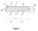
- FIG. 1 a schematic cross-section of an extruder (2) suitable for performing a method according to a particular embodiment of the present invention is shown.
- a feeder i.e. a material inlet (1)
- a single screw (3) is represented in the extruder (2) and the transport direction (4) is indicated by arrows.
- the feed-end (12) of the screw (3) is shown.
- the extruder (2) is divided in a first part (8) comprising heating means (5) and a second part (9) comprising cooling means (6).
- An injection port (7) is represented between the first (8) and second part (9).
- the extruder (2) ends with a die (11), i.e. a shaping tool.
- a styrenic polymer composition, a CO 2 releasing chemical blowing agent and optionally other additives are added as a premix in the extruder (2) via the feeder (1).
- the premix is then heated and plasticised by the heating means (5) and the screw (3) to obtain a plasticised mixture at the end of the first part (8) of the extruder (2).
- Pentane is then added under pressure through the injection port (7).
- the plasticised mixture now comprising both the chemical blowing agent and the physical blowing agent is kneaded and pressurized until a single phase mixture is obtained.
- the single phase mixture, while progressing through the second part (9) of the extruder (2) is gradually cooled down by the cooling means (6) and is extruded through the die (11).
- the styrenic polymer foam profiles produced according to any embodiments of the present invention may have a surface Shore hardness D of 35 or more.
- the surface Shore hardness D can be comprised between 35 and 55.
- Shore hardness D can be measured according to NEN-EN-ISO 868, DIN 53505, or ASTM D2240.
- These profiles may comprise very sharp elements of detail D or edges E having a radius of 1 mm or less.
- the radius of an element of detail or of an edge is evaluated as follow in the case of right angles: A right angle is in theory perfectly sharp and has a radius of zero.
- a right angle such as the right angle of an edge E or the right angle of an element of detail D (see Fig. 2 ) of a profile 13 can be characterized by the radius R of the circle which curvature equal the curvature of the rounded right angle (see Fig 3 for three examples of right angles. From top to bottom, the sharpness decreases and the radius increases). A smaller radius for an element of detail means a sharper detail. A small radius for an edge means a sharp edge.
- the initial tack may be 140 Kg/cm 2 or more.
Abstract
- a styrenic polymer composition,
- a chemical blowing agent, e.g. in a quantity of 0.1 to 1.5 %wt related to the weight of the styrenic polymer composition. and
In addition a physical blowing agent is added, e.g. at a quantity of 5*10-2 to 1.6*10-1 mol/Kg of the styrenic polymer composition, and under sufficient pressure and heat to obtain a single phase mixture.
Description
- The present invention relates to a styrenic polymer foam and a method and apparatus for producing the same.
- High density foamed polystyrene profiles of 400 kg/m3 or higher are well known in the art of building decoration. They can be produced with sharp edges and smooth surfaces. Some efforts have been made in the art to obtain polystyrene profiles with a lower density while keeping similar esthetical properties. For instance, the use of supercritical CO2 gas has been proposed. The use of CO2 gas for this purpose is far from optimal because it leads to a very fast expansion of the polystyrene, leading to defective cell structures and consequently to shrinkage during the cooling process. As a consequence, complicated and expensive shaping tools are required to obtain acceptable profile shapes in spite of the high degree of shrinkage. Moreover, the homogeneous incorporation of supercritical CO2 in polystyrene is often problematic. Additionally, the fast expansion of the polystyrene under the action of the CO2 gas leads to high radial contact forces of the melt onto the calibration surface. These high radial forces increase the friction between the melt and the calibration surface to such an extent that the axial force needed to pull the polystyrene through the calibration unit must be increased. This increases the likelihood of fractures at the melt surface, and can lead to the rupture of the extrudate. Lubricants, sometimes in large amounts, are therefore often used in the prior art to avoid such problems. This lubricant is usually introduced in the die between the melt flow and the wall of the die land. There is therefore a need in the art for new and improved methods for producing foamed styrenic polymer profiles.
- It is an object of the present invention to provide good apparatus or methods for producing styrenic polymer foams of good quality in a cost-efficient way.
- The above objective is accomplished by a method and device according to the present invention.
- It is an embodiment of the present invention to provide a method for producing a styrenic polymer foam taking advantage of the synergetic effect existing when a chemical blowing agent and a physical blowing agent are used in the same extrusion process. The chemical blowing agent, aside from its blowing effect, can play the role of a nucleating agent for the physical blowing agent. An advantage of the present invention is that the homogeneity of the cell sizes and their distribution in the polymer material is particularly good. The chemical blowing agent, releasing a gas, is responsible for the initial fast foaming of the styrenic polymer composition at the exit of the die. This fast foaming process enables filling in efficiently an optionally present calibrator in an initial stage of the blowing process. The physical blowing agent, preferably having a lower vapour pressure than the gas released by the chemical blowing agent, has its foaming activity extending over a larger range of temperature and permits therefore to extend the foaming activity to lower temperatures where a stronger structural strength exists in the foam. This temperature can for instance be down to 55°C, 50°C, 45°C, 40°C or 35°C. As a result, shrinkage of the foam can be remarkably reduced or suppressed. For instance, n-pentane can extend its foaming activity down to temperatures as low as 35°C.
- In a first aspect, the present invention relates to a method for producing a styrenic polymer foam. In a first embodiment, the present invention comprise the steps of:
- (i) mixing in an extruder:
- a styrenic polymer composition,
- a chemical blowing agent, e.g. in a quantity of 0.1 to 1.5 %wt related to the weight of the styrenic polymer composition, and
- a physical blowing agent, e.g. at a quantity of 5*10-2 to 1.6*10-1 mol/Kg of the styrenic polymer composition,
- (ii) extruding said mixture through a shaping tool in order to form a foam.
- In a second embodiment, the present invention also relates to a method for producing a styrenic polymer foam comprising the steps of:
- (i) mixing in an extruder:
- a styrenic polymer composition,
- a chemical blowing agent, e.g. in a quantity of 0.1 to 1.5 %wt related to the weight of the styrenic polymer composition, and
- a physical blowing agent, e.g. at a quantity of 0.3 to 1.2 %wt, optionally of 0.6 to 1.0 %wt, or optionally of 0.7 to 0.9 %wt related to the weight of the styrenic polymer composition,
- (ii) extruding said mixture through a shaping tool in order to form a foam.
- In another embodiment of this first aspect, the present invention relates to a method for producing a styrenic polymer foam profile having a density between 160 and 240 Kg/m3 comprising the steps of:
- (i) Mixing in an extruder:
- a styrenic polymer composition,
- a chemical blowing agent in a quantity of 0.1 to 1.5 %wt related to the weight of the styrenic polymer composition, and
- a physical blowing agent at a quantity of 9*10-2 to 1.3*10-1 mol/Kg of the styrenic polymer composition (or at a quantity of 0.3 to 1.2 %wt, optionally of 0.6 to 1.0 %wt, or optionally of 0.7 to 0.9 %wt related to the weight of the styrenic polymer composition),
- (ii) gradually cooling down said mixture to a temperature,
- (iii) performing an initial foaming of said mixture upon extruding said mixture through a shaping tool, wherein said initial foaming is caused by said chemical blowing agent, and
- (iv) passing said foam through a calibration system in order to form said styrenic polymer foam profile while extending the foaming activity to lower temperatures where a stronger structural strength exists in the foam, wherein said extended foaming activity is caused by the physical blowing agent.
- (i) Introducing in an extruder comprising a die coupled to a calibrator a styrenic polymer composition,
- (ii) Inducing at the exit of said die a first expansion of said styrenic polymer composition by introducing in said extruder a chemical blowing agent in a quantity of 0.1 to 1.5 %wt related to the weight of the styrenic polymer composition,
- (iii) Inducing in said calibrator a second expansion of said styrenic polymer composition by introducing in said extruder a physical blowing agent at a quantity of 9*10-2 to 1.3*10-1 mol/Kg of the styrenic polymer composition (or at a quantity of 0.3 to 1.2 %wt, optionally of 0.6 to 1.0 %wt, or optionally of 0.7 to 0.9 %wt related to the weight of the styrenic polymer composition), wherein said second expansion is slower than said first expansion. Preferably, said second expansion extends the foaming activity to temperatures equal or above 55°C, 50°C, 45°C, 40°C or 35°C.
- As an optional feature to any embodiment of the present invention, the styrenic polymer foam may be in the form of a profile, preferably a solid, hollow or open profile including sharp edges and/or elements of details having small radiuses. The styrenic polymer foams produced by the method of the present invention are particularly well adapted to form profiles because they combine the advantages of, on one hand, being obtainable with sharp edges and a smooth surface and, on another hand, being light and therefore inexpensive.
- As another optional feature to any embodiment of the present invention, the method of the first aspect may further comprise the step (iii) of passing the foam trough a calibration system. This is advantageous because it permits to control better the shape of the foam produced.
- It is an advantage of the present invention to provide alternative apparatus or methods for extruding styrenic polymer foams having a density controllable by the addition of blowing agents, e.g. to obtain a density inferior to 400 kg/m3. Accordingly, another optional feature to any embodiment of the present invention is a styrenic polymer foam produced having a density between 100 and 400 Kg/m3, preferably between 160 and 240 Kg/m3. This is advantageous because less material is used to obtain the same visual effect as obtained with higher densities styrenic polymer foams for a much lower production price on one hand and a lower ecological impact on another hand.
- As another optional feature to any embodiment of the present invention, the styrenic polymer composition may have a calculated or measured melt flow index of between 2.5 and 18 g/10min, preferably of between 9 and 18 g/10min at 200 °C under a load of 5 Kg according to ISO 1133. This range is advantageous because it permits a sufficient expansion of the styrenic polymer composition to obtain e.g. profiles with sharp edges while simultaneously reducing the tendency of the cells to collapse and the apparition of surface defects due to cell openings.
- As another optional feature to any embodiment of the present invention, the styrenic polymer composition may comprise two or more styrenic polymers of different melt flow indices. This is advantageous because the combining of two polymers having different melt flow indices enables optimisation of the strength of the styrenic polymer foam obtained on one hand and the foamability of the styrenic polymer composition on the other hand.
- As another optional feature to any embodiment of the present invention, the physical blowing agent may have a vapour pressure at 20°C of 2 Kpa to 1000 Kpa. This is advantageous because within this range, the physical blowing agent allows for a slower expansion of the foam than what would normally be observed when blowing agents of higher vapour pressure are used. This leads to a slower volume increase of the styrenic polymer foam and therefore to less contact forces between the styrenic polymer foam and the optional calibrator. This also leads to stronger cell structures due to a faster cooling of the styrenic polymer foam. A stronger cell structure permits to avoid collapsing of the cells and the resulting shrinkage of the styrenic polymer foam.
- As another optional feature to any embodiment of the present invention, the physical blowing agent is selected from the group consisting of butane and isomers thereof, pentane and isomers thereof, ethanol, acetone and mixtures thereof. Preferably the physical blowing agent is pentane. Pentane is advantageous because it combines a relatively low vapour pressure, a relatively good solubility in the polystyrene, a relatively low toxicity and a relatively high vaporisation enthalpy (helping a fast cooling of the foam). It also diminish less the Tg and/or the Vicatt temperature of the styrenic polymer composition than equivalent amount of CO2. Yet another advantage of pentane is that it reduces very efficiently the shrinkage of the foam in the (optional) calibrator.
- As another optional feature to any embodiment of the present invention, prior to step (ii), the mixture is gradually cooled down to a temperature above 135°C. This is advantageous because by cooling the mixture in this way, the foaming gases are maintained dissolved therein at a pressure not causing excessive mechanical load on the extruder. The higher the melt temperature of the extrudate, the lower the pressures required to keep the blowing agents dissolved in the styrenic polymer composition and the easier it is to foam the styrenic polymer composition to a low density as the viscosity of the polymer to be formed is lower.
- As another optional feature to any embodiment of the present invention, step (i) comprises the steps of:
- a) introducing said styrenic polymer composition and said chemical blowing agent as a premix via the feeder of the extruder,
- b) mixing and heating said premix in order to obtain a plasticized mixture,
- c) introducing said physical blowing agent under pressure through an inlet performed in the extruder, downstream from the feeder, and
- d) kneading and pressurizing said plasticized mixture and said second blowing agent until said single phase mixture is obtained.
- As another optional feature to any embodiment of the present invention the styrenic polymer composition comprises or consists of one or more polystyrene polymers. This is advantageous because polystyrene is both cheap and effective when used in the present invention.
- Particular and preferred aspects of the invention are set out in the accompanying independent and dependent claims. Features from the dependent claims may be combined with features of the independent claims and with features of other dependent claims as appropriate and not merely as explicitly set out in the claims.
- Although there has been constant improvement, change and evolution of devices and methods in this field, the present concepts are believed to represent substantial new and novel improvements, including departures from prior practices, resulting in the provision of more efficient, stable and reliable devices and methods of this nature.
- The above and other characteristics, features and advantages of the present invention will become apparent from the following detailed description, taken in conjunction with the accompanying drawings, which illustrate, by way of example, the principles of the invention. This description is given for the sake of example only, without limiting the scope of the invention. The reference figures quoted below refer to the attached drawings.
-
-
Fig. 1 is a schematic representation of a cross-sectional view of an extruder suitable for performing a method according to an embodiment of the present invention. -
Fig. 2 is an example of profile obtained via a method according to an embodiment of the present invention. -
Fig. 3 is a schematic explanation of what means elements of detail or edges having a "radius". - The present invention will be described with respect to particular embodiments and with reference to certain drawings but the invention is not limited thereto but only by the claims. The drawings described are only schematic and are non-limiting. In the drawings, the size of some of the elements may be exaggerated and not drawn on scale for illustrative purposes. The dimensions and the relative dimensions do not correspond to actual reductions to practice of the invention.
- Furthermore, the terms first, second, third and the like in the description and in the claims, are used for distinguishing between similar elements and not necessarily for describing a sequence, either temporally, spatially, in ranking or in any other manner. It is to be understood that the terms so used are interchangeable under appropriate circumstances and that the embodiments of the invention described herein are capable of operation in other sequences than described or illustrated herein.
- Moreover, the terms top, bottom, over, under and the like in the description and the claims are used for descriptive purposes and not necessarily for describing relative positions. It is to be understood that the terms so used are interchangeable under appropriate circumstances and that the embodiments of the invention described herein are capable of operation in other orientations than described or illustrated herein.
- It is to be noticed that the term "comprising", used in the claims, should not be interpreted as being restricted to the means listed thereafter; it does not exclude other elements or steps. It is thus to be interpreted as specifying the presence of the stated features, integers, steps or components as referred to, but does not preclude the presence or addition of one or more other features, integers, steps or components, or groups thereof. Thus, the scope of the expression "a device comprising means A and B" should not be limited to devices consisting only of components A and B. It means that with respect to the present invention, the only relevant components of the device are A and B.
- Similarly, it is to be noticed that the term "coupled", also used in the claims, should not be interpreted as being restricted to direct connections only. The terms "coupled" and "connected", along with their derivatives, may be used. It should be understood that these terms are not intended as synonyms for each other. Thus, the scope of the expression "a device A coupled to a device B" should not be limited to devices or systems wherein an output of device A is directly connected to an input of device B. It means that there exists a path between an output of A and an input of B which may be a path including other devices or means. "Coupled" may mean that two or more elements are either in direct physical or electrical contact, or that two or more elements are not in direct contact with each other but yet still co-operate or interact with each other.
- Reference throughout this specification to "one embodiment" or "an embodiment" means that a particular feature, structure or characteristic described in connection with the embodiment is included in at least one embodiment of the present invention. Thus, appearances of the phrases "in one embodiment" or "in an embodiment" in various places throughout this specification are not necessarily all referring to the same embodiment, but may. Furthermore, the particular features, structures or characteristics may be combined in any suitable manner, as would be apparent to one of ordinary skill in the art from this disclosure, in one or more embodiments.
- Similarly it should be appreciated that in the description of exemplary embodiments of the invention, various features of the invention are sometimes grouped together in a single embodiment, figure, or description thereof for the purpose of streamlining the disclosure and aiding in the understanding of one or more of the various inventive aspects. This method of disclosure, however, is not to be interpreted as reflecting an intention that the claimed invention requires more features than are expressly recited in each claim. Rather, as the following claims reflect, inventive aspects lie in less than all features of a single foregoing disclosed embodiment. Thus, the claims following the detailed description are hereby expressly incorporated into this detailed description, with each claim standing on its own as a separate embodiment of this invention.
- Furthermore, while some embodiments described herein include some but not other features included in other embodiments, combinations of features of different embodiments are meant to be within the scope of the invention, and form different embodiments, as would be understood by those in the art. For example, in the following claims, any of the claimed embodiments can be used in any combination.
- Furthermore, an element described herein of an apparatus embodiment is an example of a means for carrying out the function performed by the element for the purpose of carrying out the invention.
- In the description provided herein, numerous specific details are set forth. However, it is understood that embodiments of the invention may be practiced without these specific details. In other instances, well-known methods, structures and techniques have not been shown in detail in order not to obscure an understanding of this description.
- The following terms are provided solely to aid in the understanding of the invention.
- The term "profile" as used herein and unless provided otherwise refers to an extruded plastic product, excluding film or sheets having a characteristic constant axial section. Profiles include sections such as but not limited to quadratic, circular, U-shaped, T-shaped, L-shaped or any other shaped section, such as e.g. complex sections of any possible shape.
- The invention will now be described by a detailed description of several embodiments of the invention. It is clear that other embodiments of the invention can be configured according to the knowledge of persons skilled in the art without departing from the true spirit or technical teaching of the invention, the invention being limited only by the terms of the appended claims. The teachings of the present invention permit the design of improved methods and apparatus for producing styrenic polymer foams, e.g. of densities lower than 400 kg/m3 of enhanced quality in a cost efficient way.
In a first aspect, the present invention relates to a method for producing a styrenic polymer foam. - In an embodiment of the first aspect, the method comprises the steps of:
- (i) mixing in an extruder:
- a styrenic polymer composition,
- a chemical blowing agent in a quantity of 0.1 to 1.5 %wt related to the weight of the styrenic polymer composition, and
- a physical blowing agent at a quantity of 5*10-2 to 1.6*10-1 mol/Kg of the styrenic polymer composition,
- (ii) extruding said mixture through a shaping tool in order to form a foam.
- Suitable styrenic polymer compositions include but are not limited to styrenic homopolymers and copolymers of styrenic compounds and copolymerizable ethylenically unsaturated comonomers. The styrenic polymer composition may further include minor proportions of non-styrenic polymers. The styrenic polymer composition may be comprised solely of one or more styrenic homopolymers, one or more styrenic copolymers, a blend of one or more of each of styrenic homopolymers and copolymers, or blends of any of the foregoing with a non-styrenic polymer. Regardless of composition, the styrenic polymer material comprises greater than 50 and preferably greater than 70 weight percent of styrenic monomeric units. Most preferably, the styrenic polymer material is comprised entirely of styrenic monomeric units. Suitable styrenic polymers include those derived from styrenic compounds such as styrene, alphamethylstyrene, vinyl benzene, vinyl toluene, chlorostyrene, and bromostyrene. Minor amounts of monoethylenically unsaturated compounds may be copolymerized with styrenic compounds. Examples of copolymerizable compounds include but are not limited to acrylic acid, methacrylic acid, ethacrylic acid, maleic acid, itaconic acid, acrylonitrile, maleic anhydride, methyl acrylate, ethyl acrylate, butyl acrylate, propyl acrylate, methyl methacrylate, vinyl acetate, vinyl alcohol, amides, 1,3-butadiene, 1,3-pentadiene, and 1,4-hexadiene. Preferred structures comprise substantially polystyrene (that is, greater than 80 percent by weight) and most preferably entirely of polystyrene because polystyrene foam is economical, and may form good profiles with smooth surface and sharp edges when used according to embodiments of the present invention. For instance, a general purpose polystyrene (GPPS) is suitable.
- For instance, the styrenic polymer composition can consist in a blend of a first styrenic polymer having a relatively high melt flow index (MFI) and a second styrenic polymer having a relatively low MFI. The use of such a blend can be advantageous because the lower MFI polymer provides improved strength and/or hardness and the higher MFI polymer is easier to foam and/or permits to obtain profiles with sharper edges and/or sharper details. Playing on the ratio of polymers having different MFI permits therefore to optimize the process and the properties of the obtained foam.
- The styrenic polymer composition has preferably a calculated or measured (according to ISO 1133, at 200 °C under a load of 5 Kg) melt flow index (MFI) of between 2.5 and 18 g/10min, preferably of between 9 and 18 g/10min. In order to calculate the melt flow index of a mixture having two or more components, the following evaluation method can be used if the MFI and the weight fraction of each component is known:

wherein MFImixture is the melt flow index of the mixture, Wi is the weight fraction of component i and MFIi is the melt flow index of component i. - For example, in one specific embodiment of the present invention, the styrenic polymer used can be a mixture comprising 50%wt of a first polystyrene having an MFI of 7.5 (e.g. Empera™ 153F from the company NOVA Innovene International SA) and 50%wt of a second polystyrene (e.g. Empera™ 156F from the company NOVA Innovene International SA) having an MFI of 24 ; the resulting calculated MFI for the mixture would than be 13.4.
- The Vicat temperature of the styrenic polymer composition is preferably 90 to 110°C, more preferably 95 to 105°C. This is advantageous because these ranges are good compromise between the ease of blowing and the possibility to obtain profiles with sharp edges. With those relatively high Vicat temperature, stiffness of the cell structure is reached at a relatively high temperature, i.e. fast enough upon cooling to obtain a profile keeping the its shape.
- The foaming of the styrenic polymer composition is obtained by incorporating in the styrenic polymer composition blowing agents. The blowing agents used in this first aspect of the present invention are at least a chemical blowing agent and a physical blowing agent.
- A chemical blowing agent is a chemical agent, e.g. particularly a solid but a liquid is not excluded from this invention, which undergoes heat-induced chemical change, e.g. decomposition, in the polymer composition causing formation of a gas. This decomposition is usually triggered by heat, but can alternatively be triggered by the presence of a co-reactant. For instance, a chemical blowing agent could be triggered by the presence of water, whereby water is included in the formulation but only becomes available for chemical reaction upon the addition of heat. E.g. such would be the case for certain hydrated salt compounds mixed with the chemical blowing agent sodium borohydride.
- Suitable chemical blowing agents include but are not limited to bicarbonate - acid mixture (e.g. a sodium bicarbonate - citric acid mixture or a sodium bicarbonate - citric acid - citrate mixture), organic acid salts, azodicarbonamide, azobisformamide, azobisisobutyrolnitrile, diazoaminobenzene, 4,4'-oxybis(benzene sulfonyl hydrazide) (OBSH), N,N'-dinitrosopentamethyltetramine (DNPA), sodium borohydride, p-toluenesulfonyl hydrazide, p-toluenesulfonyl semicarbazide, diisopropylhydrazodicarboxylate, 5-phenyl-3,6-dihydro-1,3,4-oxadiazin-2-one, potassium hydrogencarbonate, polycarbonic acid, ammonium carbonate, ammonium carbamate, ammonium acetate, ammonium diethyldithiocarbamate, and other chemical blowing agents well known in the art. Mixtures of chemical blowing agents can be used as well.
- One advantage of chemical blowing agents is that they are easy to handle and the carbon dioxide or nitrogen gas typically evolved is relatively inert, non-flammable, and non-toxic. Preferably, the chemical blowing agent used releases CO2 as a gas upon decomposition. Examples of commercially available CO2 releasing blowing agents are TRACEL™ NC 7155 and TRACEL™ INC 7207F from the firm Tramaco among others. An advantage of CO2 releasing blowing agents is that they are themselves usually non-toxic, which makes them easy and safe to work with. On the other hand, the CO2 released gives rise to a slower expansion than N2.
- The chemical blowing agent is preferably used in a quantity of 0.1 to 1.5 % wt. For instance it can be used in a quantity of 0.5 to 1.5 %wt or 0.7 to 1.5 %wt. Preferably, it is used in a quantity of 0.3 to 1.2 %wt, more preferably 0.5 to 1 %wt, even more preferably 0.5 to 0.8 %wt and most preferably 0.6 to 0.8 %wt related to the weight of the styrenic polymer composition. The chemical blowing agent may be used pure or in the form of a compound combining the chemical blowing agent as such with additives. For instance, TRACEL™ NC 7155 is sold under the form of white granules comprising about 70% of the actual blowing agent. The use of such granules has the advantage to enable an easier mixing with the styrenic polymer composition, e.g. when the styrenic polymer composition is also in the form of granules. The use of 1% of TRACEL™ NC 7155 should therefore be interpreted as the use of 0.7% of chemical blowing agent.
- The use of a chemical blowing agent is also advantageous because it can serve as a nucleating agent for a physical blowing agent. A physical blowing agent is a material that is normally a gas or a low boiling point liquid at room temperature and is introduced into the melt in this form. A proper physical blowing agent can change phase but usually does not decompose significantly at the temperatures reached in the extruder during the extrusion process.
- Suitable physical blowing agents include but are not limited to lower alcohols such as but not limited to methanol, ethanol, n-propanol and isopropanol; hydrocarbons, especially alkanes having up to six carbon atoms such as methane, ethane, propane, n-butane, isobutane, n-pentane, isopentane, neopentane, hexane, cyclobutane and cyclopentane; ketones such as e.g. acetone, alkyl ethers such as but not limited to dimethyl ether, diethyl ether and methyl ethyl ether; water, carbon dioxide, nitrogen, air (nitrogen and oxygen blend), SF 6, nitrous oxide, and noble gases such argon, helium or xenon. Mixtures of two or more of these physical blowing agents can also be used.
- Preferably, the physical blowing agent(s) used has (have) a low vapour pressure at 20°C of 2kPa to 1000 kPa, preferably 2 kPa to 250 kPa. For instance, gaseous CO2 has a vapour pressure at 20°C of c.a. 5730 kPa. Although gaseous CO2 is usable as the physical blowing agent within the present invention, it is less preferred. The vapour pressure at 20°C is c.a. 56.6 kPa for n-pentane, c.a. 78 kPa for isopentane and c.a. 36 kPa for cyclopentane.
- Preferred physical blowing agent(s) are methanol, ethanol, n-propanol, isopropanol, n-butane, isobutane, n-pentane, isopentane, neopentane, cyclopentane, acetone, water and mixtures thereof. More preferably, the physical blowing agent is selected from the group consisting of n-butane, isobutane, n-pentane, isopentane, neopentane, cyclopentane, acetone and mixture thereof. More preferably, the physical blowing agent is selected from the group consisting of n-butane, isobutane, n-pentane, isopentane, neopentane, cyclopentane and mixture thereof. Even more preferably, the physical blowing agent is selected from the group consisting of n-pentane, isopentane, neopentane or a mixture thereof. Most preferably, the physical blowing agent is n-pentane. In presence of a chemical blowing agent, the use of a certain quantity of physical blowing agent such as e.g. pentane, allows control and adjustment of the speed of the foaming process and in particular control and adjustment of the expansion ratio.
- The physical blowing agent is preferably used in a quantity of 5*10-2 to 1.6*10-1 mol/Kg of styrenic polymer composition, preferably of 7*10-2 to 1.4*10-1 mol/Kg of styrenic polymer composition, more preferably of 9*10-2 to 1.3*10-1 mol/Kg of styrenic polymer composition, most preferably of 1.0 *10-1 to 1.2*10-1 mol/Kg of styrenic polymer composition
- Various additives can be added such as but not limited to impact modifiers, nucleation agents (e.g. talc, calcium carbonate, silica,...), fire retardants, UV-stabilizers, pigments, antioxidants, fillers, reinforcement fibers, lubricants (e.g. fatty acid amids, polyethylene waxes, styrenic waxes, silicone compounds...), among others. Preferably, a nucleating agent is used. Most preferably, this nucleating agent is talc (e.g. from a 50% masterbatch).
- The extruder can be a single extruder or a tandem extruder (i.e. two coupled sub-extruders). The extruder (or each sub-extruder) can comprise one or two screws. If the extruder or one (or both) of the sub-extruders comprise two screws, they can be either co-rotating or counter rotating. Preferably, the extruder has a single screw or is a tandem extruder composed of two sub-extruders, each having a single screw. One or more dosing units are preferably coupled to the extruder. The dosing units for the styrenic polymer composition, the chemical blowing agent and the optional additives are preferably coupled to the feeder of the extruder while the dosing unit for the physical blowing agent can be either coupled to the feeder or coupled to an injection port downstream to the feeder. The extruder is preferably divided in several zones controllable in temperature. Preferably, a first part of the extruder is adapted to heat up the fed mixture to a temperature high enough to plastify it and to obtain an homogeneous melt while a second part of the extruder is adapted to progressively cool the plastified mixture down to the extrusion temperature. The first part may have a length to diameter ratio (LD) of 12 to 20, preferably 14 to 18, most preferably 15 to 17. The second part may have a length to diameter ratio (LD) of 15 to 35, preferably 16 to 32, more preferably 18 to 30, even more preferably 20 to 28, even more preferably, 22 to 26, most preferably, 23 to 25. The extruder has preferably a length to diameter ratio of 40 or more. In some embodiments, the first part correspond to the first sub-extruder of a tandem extruder and the second part correspond to the second sub-extruder of the tandem extruder.
- Prior to step (i), a dosing, such as for instance a gravimetric dosing, of the different components is preferably performed.
- The chemical blowing agent is preferably added to the neat styrenic polymer composition, mixed, and fed into an extruder together with the styrenic polymer composition via the feeder of the extruder. The mixing can for instance be performed in a mixing hopper. The mixture is then heated to a temperature above the Vicat temperature of the styrenic polymer composition to ensure intimate mixing and further heated to the activation temperature of the chemical blowing agent, resulting in decomposition of the chemical blowing agent. The gas formed on activation is substantially dissolved or dispersed in the melt mixture. The temperature and pressure of the system are controlled to maintain substantially a single phase.
- If the physical blowing agent is a liquid at room temperature and 1 atm, it can be incorporate directly in the neat styrenic polymer composition, i.e. at the same stage as the adding of the chemical blowing agent. Preferably, the physical blowing agent is introduced in the extruder via an injection port situated downstream from the feeder. Preferably, the introduction of the physical blowing agent is performed at a position of the extruder where the chemical blowing agent (fed in earlier) has already decomposed. Preferably, the introduction of the physical blowing agent is operated at an LD of 12 to 20, preferably 14 to 18, more preferably 15 to 17 from the beginning of the extruder (i.e. from the beginning of the feed-end of the screw or the first screw of this extruder). Preferably, the introduction of the physical blowing agent is performed at the end of the first part or at the beginning of the second part or between the first part and the second part of the extruder. In the case of a tandem extruder, the physical blowing agent is preferably introduced between the first sub-extruder and the second sub-extruder. The physical blowing agent is preferably added under pressure. Preferably, a sufficient pressure is used to maintain the physical blowing agent in a liquid form at the temperature of the melt. In the embodiments where the physical blowing agent is introduced at a position of the extruder where the chemical blowing agent has already decomposed, the mixture (now incorporating the physical blowing agent and the pressurized gas released by the chemical blowing agent) is further plasticized and preferably kept under sufficient pressure to obtain an homogeneous single phase mixture.
- For instance, the method of the present invention may comprise the steps of:
- a) introducing said styrenic polymer composition and said chemical blowing agent as a premix via the feeder of the extruder,
- b) mixing and heating said premix in order to obtain a plasticized mixture,
- c) introducing said physical blowing agent under pressure through an inlet performed in the extruder, dowstream from the feeder, and
- d) kneading and pressurizing the plasticized mixture and the second blowing agent until a single phase mixture is obtained.
- After cooling to a temperature above 135°C, the single phase mixture enters a shaping tool (e.g. a die) that imposes its shape to the polymeric mixture. Upon exiting the die, the polymeric mixture is foamed due to a pressure drop. In order to avoid foaming activity in the die, i.e. in order to keep the blowing agents dissolved in the melt, the pressure of the melt is preferably kept at a sufficient level until the melt reaches the outlet of the shaping tool. How rapidly the pressure is preferably decreased at the outlet of the die is better determined experimentally and adapted in function of the rheological properties of the melt as is well known by the person skilled in the art. One way to control the pressure at this level is to play on the size and design of the die endplate split and/or the length of the land. Another way to control the pressure at this level is to control the temperature of the die.
- The expansion of the styrenic polymer foam operates slowly and is preferably controlled by passing the styrenic polymer foam through a calibration system, optionally controlled in temperature. In order to reduce friction between the calibration system and the foaming styrenic polymer, one or more of the following can be done: a) the geometry of the calibration unit can preferably be adapted to the changing shape of the die output during foaming, b) the foam surface is preferably kept at a temperature below the Tg of the styrenic polymer, c) the calibration unit is preferably coated on its inside with a low-friction coating. The calibration system preferably participate in the cooling of the foamed polymeric mixture. The styrenic polymer foam may also pass through a water bath for cooling purpose. The formed styrenic polymer foam is most conveniently pulled by e.g. a haul off or any other motorised pulling device known from the person skilled in the art. The haul off preferably comprises pads shaped in such a way as to minimize the contact forces of the pads with the surface of the styrenic polymer foam. The styrenic polymer foam has preferably already a stable geometry before it contacts the pulling device (e.g. the haul off pads). It is also possible to apply decorative motives on the styrenic polymer foam by using e.g. heated embossing rolls. The embossing rolls are preferably installed in the calibration line. The styrenic polymer foam can then be cut to size with e.g. a saw.
- The styrenic polymer foam obtained has preferably a closed cell structure and a smooth surface. Its density ranges preferably between 100 and 400 Kg/m3, most preferably between 150 and 250 Kg/m3. Experiments have shown that operating in accordance with the present invention forms profiles with sharp edges and detailed motives. The styrenic polymer foam obtained may contain in some embodiments up to 2%wt of additives.
- In
Figure 1 , a schematic cross-section of an extruder (2) suitable for performing a method according to a particular embodiment of the present invention is shown. On the left side of the scheme, a feeder, i.e. a material inlet (1) is represented. A single screw (3) is represented in the extruder (2) and the transport direction (4) is indicated by arrows. The feed-end (12) of the screw (3) is shown. The extruder (2) is divided in a first part (8) comprising heating means (5) and a second part (9) comprising cooling means (6). An injection port (7) is represented between the first (8) and second part (9). The extruder (2) ends with a die (11), i.e. a shaping tool. - In a specific embodiment of the present invention, a styrenic polymer composition, a CO2 releasing chemical blowing agent and optionally other additives are added as a premix in the extruder (2) via the feeder (1). The premix is then heated and plasticised by the heating means (5) and the screw (3) to obtain a plasticised mixture at the end of the first part (8) of the extruder (2). Pentane is then added under pressure through the injection port (7). The plasticised mixture now comprising both the chemical blowing agent and the physical blowing agent is kneaded and pressurized until a single phase mixture is obtained. The single phase mixture, while progressing through the second part (9) of the extruder (2) is gradually cooled down by the cooling means (6) and is extruded through the die (11).
The styrenic polymer foam profiles produced according to any embodiments of the present invention may have a surface Shore hardness D of 35 or more. For instance the surface Shore hardness D can be comprised between 35 and 55. Shore hardness D can be measured according to NEN-EN-ISO 868, DIN 53505, or ASTM D2240. These profiles may comprise very sharp elements of detail D or edges E having a radius of 1 mm or less. The radius of an element of detail or of an edge is evaluated as follow in the case of right angles: A right angle is in theory perfectly sharp and has a radius of zero. In reality, right angles obtained via a manufacture process always appear rounded when observed under sufficient magnification. A right angle such as the right angle of an edge E or the right angle of an element of detail D (seeFig. 2 ) of aprofile 13 can be characterized by the radius R of the circle which curvature equal the curvature of the rounded right angle (seeFig 3 for three examples of right angles. From top to bottom, the sharpness decreases and the radius increases). A smaller radius for an element of detail means a sharper detail. A small radius for an edge means a sharp edge. The initial tack may be 140 Kg/cm2 or more. This initial tack is measured for the glue ORAC DECOFIX Pro™ as follow: Use is made of a rheometer having a plate-plate configuration wherein each of the samples plates have a diameter of 2 cm and wherein the sample plates are spaced apart by 1000 µm. The glue is then introduced between the plates. The excess glue is then removed without moving the sample plates and the assembly sample plate-glue-sample plate is allowed to rest for 1 minute. A continuous flow measurement is then performed wherein the force is increased from 10 Pa to 2500 Pa in 3 minutes by steps of 20 Pa. The force at which the first displacement within the sample plate-glue-sample plate occurs is the "initial tack" of the sample for the glue concerned (here ORAC DECOFIX Pro™). The paint adhesion of a primer coat (PRIMER AQUASTAR™ 09645/2342 WIT) is also very good as it may correspond to a cross-cut test grade of 1 to 2 when measured according DIN 53151. After application of the paint and drying, the sample is scratched in two directions with the cross cutter during 24 hours. A cross-cut test grade of 1 means that detachment of small flakes of the coating at the intersection of the cuts is observed but that the affected cross-cut area is not significantly greater than 5%. A cross-cut test grade of 2 means that the coating has flaked along the edges and /or at the intersections of the cuts. A cross-cut area significantly greater than 5%, but not significantly greater than 15%, is affected. The good paint adhesion is an indication of high surface tension present on the surface of the sample. - In a first step, a mixture comprising:
- 50%wt of a first general purpose polystyrene (EMPERA™ 156F) having a MFI of 24 and a Vicat softening temperature of 101 °C,
- 50%wt of a second general purpose polystyrene (EMPERA™ 153F) having a MFI of 7.5 and a Vicat softening temperature of 101 °C,
- Talc as a nucleating agent, and
- 0.7%wt of a CO2 releasing chemical agent (1 %wt of TRACEL™ NC 7155 as a 70% masterbatch),
- In a second step, the mixture was mixed and heated above 135°C in the extruder in order to obtain a plasticized mixture and to decompose the chemical blowing agent. In a third step, 0.8%wt of n-pentane was injected under 250 bars through an entry port situated at LD 16, i.e. between the heating section of the extruder and the cooling section of the extruder. In a fourth step, the mixture is gradually cooled down while keeping the pressure in the extruder high enough to avoid expansion of the blowing agents. The cooled melt then passed through a die and expanded directly after exiting this die. The melt then passed in calibrators where it was further cooled. The polystyrene foam profile obtained had a density of 200 Kg/m3, sharp edges and a smooth surface.
- It is to be understood that although preferred embodiments, specific constructions and configurations, as well as materials, have been discussed herein for devices according to the present invention, various changes or modifications in form and detail may be made without departing from the scope and spirit of this invention. For example, any formulas given above are merely representative of procedures that may be used. Functionality may be added or deleted from the block diagrams and operations may be interchanged among functional blocks. Steps may be added or deleted to methods described within the scope of the present invention.
It is an advantage of the present invention to provide apparatus or methods for extruding styrenic polymer foams which have reduced shrinkage during the cooling stage. It is also an advantage of the present invention to provide apparatus or methods for producing styrenic polymer foams which reduce the need for complicated and expensive shaping tools. It is also an advantage of the present invention to provide apparatus or methods for producing styrenic polymer foams wherein the contact forces between the expanding styrenic polymer and the shaping tools (die and/or calibrator) used to give it its form is reduced and the need for lubricants is therefore diminished.
Claims (15)
- A method for producing a styrenic polymer foam profile having a density between 160 and 240 Kg/m3 comprising the steps of:(i) Mixing in an extruder (2):- a styrenic polymer composition,- a chemical blowing agent in a quantity of 0.1 to 1.5 %wt related to the weight of the styrenic polymer composition, and- a physical blowing agent at a quantity of 9*10-2 to 1.3*10-1 mol/Kg of the styrenic polymer composition,under sufficient pressure and heat to obtain a single phase mixture,(ii) gradually cooling down said mixture to a temperature,(iii) performing an initial foaming of said mixture upon extruding said mixture through a shaping tool (11), wherein said initial foaming is caused by said chemical blowing agent, and(iv) passing said foam through a calibration system in order to form said styrenic polymer foam profile while extending the foaming activity to lower temperatures where a stronger structural strength exists in the foam, wherein said extended foaming activity is caused by the physical blowing agent.
- A method according to claim 1, wherein said temperature is 135°C.
- A method according to any of claim 1 or claim 2, wherein said styrenic polymer composition has a calculated or measured melt flow index of between 2.5 and 18 g/10min at 200 °C under a load of 5 Kg according to ISO 1133.
- A method according to any of claims 1 to 3, wherein said styrenic polymer composition comprises two or more styrenic polymers of different melt flow indices.
- A method according to any of claims 1 to 4, wherein said physical blowing agent has a vapour pressure at 20°C of 2 Kpa to 1000 Kpa
- A method according to any of claims 1 to 5, wherein said physical blowing agent is selected from the group consisting of n-butane, isobutane, n-pentane, isopentane, neopentane, cyclopentane, acetone and mixture thereof.
- A method according to claim 6, wherein said physical blowing agent is n-pentane.
- A method according to any of claims 1 to 7, wherein step (i) comprises the steps of:a) introducing said styrenic polymer composition and said chemical blowing agent as a premix via a material inlet (1) of the extruder (2),b) mixing and heating said premix in order to obtain a plasticized mixture,c) introducing said physical blowing agent under pressure through an injection port (7) performed in the extruder (2), downstream from the material inlet (1), andd) kneading and pressurizing said plasticized mixture and said second blowing agent until said single phase mixture is obtained.
- A method according to claim 8, wherein step (c) is performed at a length to diameter ratio (LD) of 12 to 20 as measured from the beginning of the feed-end (12) of the first or only screw (3) of the extruder (2).
- A method according to any preceding claims wherein said styrenic polymer composition consists in one or more polystyrene polymers.
- An apparatus for producing styrenic polymer foams, said apparatus comprising:an extruder (2) having:• a means (1) for introducing a styrenic polymer composition,• a means (1) for introducing a chemical blowing agent in a quantity of 0.1 to 1.5 %wt related to the weight of the styrenic polymer composition, and• a means (7) for introducing a physical blowing agent at a quantity of 9*10-2 to 1.3*10-1 mol/Kg of the styrenic polymer composition under sufficient pressure and heat to obtain a single phase mixture, the means for introducing a physical blowing agent being downstream of the means for introducing a chemical blowing agent, and• a shaping tool (11) for forming a foam on extruding said mixture therethrough.
- The apparatus of claim 11, further comprisinga) a material inlet (1) of the extruder (2) for introducing said styrenic polymer composition and said chemical blowing agent as a premixb) an injection port (7) for introducing said physical blowing agent under pressure into the extruder (2), downstream from the material inlet (1), andc) a calibrator to form said styrenic polymer foam profile.
- The apparatus of claim 11 or 12, the extruder having a screw with a length to diameter ratio (LD) of 12 to 20 as measured from the beginning of the feed-end (12) of the screw (3) of the extruder (2).
- A foamed profile comprising a styrenic polymer foam, obtainable by a method according to any of the claims 1 to 10, the profile being a solid, hollow or open profile.
- A method for producing a styrenic polymer foam profile having a density between 160 and 240 Kg/m3 comprising the steps of:extruding a styrenic polymer composition having a physical blowing agent and a chemical blowing agent,performing an initial foaming of said composition wherein said initial foaming is caused by said chemical blowing agent, andpassing said foam through a calibration system in order to form said styrenic polymer foam profile while extending the foaming activity to lower temperatures where a stronger structural strength exists in the foam, wherein said extended foaming activity is caused by the physical blowing agent.
Applications Claiming Priority (1)
| Application Number | Priority Date | Filing Date | Title |
|---|---|---|---|
| GBGB0709720.7A GB0709720D0 (en) | 2007-05-22 | 2007-05-22 | Process and apparatus for producing foamed styrenic polymers |
Publications (4)
| Publication Number | Publication Date |
|---|---|
| EP1995273A2 true EP1995273A2 (en) | 2008-11-26 |
| EP1995273A3 EP1995273A3 (en) | 2009-04-29 |
| EP1995273B1 EP1995273B1 (en) | 2013-01-09 |
| EP1995273B2 EP1995273B2 (en) | 2023-08-23 |
Family
ID=38234808
Family Applications (1)
| Application Number | Title | Priority Date | Filing Date |
|---|---|---|---|
| EP08156742.2A Active EP1995273B2 (en) | 2007-05-22 | 2008-05-22 | Process and apparatus for producing foamed styrenic polymers |
Country Status (2)
| Country | Link |
|---|---|
| EP (1) | EP1995273B2 (en) |
| GB (1) | GB0709720D0 (en) |
Cited By (5)
| Publication number | Priority date | Publication date | Assignee | Title |
|---|---|---|---|---|
| WO2010066331A1 (en) | 2008-12-12 | 2010-06-17 | Jackon Gmbh | Process for the preparation of an expandable polymer composition in the form of beads |
| BE1019920A5 (en) * | 2011-05-31 | 2013-02-05 | Orac Holding Nv | METHOD FOR THE CONTINUOUS MANUFACTURE OF POLYSTYRENE PROFILES |
| EP3162531A1 (en) * | 2015-10-30 | 2017-05-03 | Technoform Tailored Solutions Holding GmbH | Method for manufacturing foamed profiles and foamed profiles obtainable by the method |
| EP3666820A1 (en) * | 2018-12-11 | 2020-06-17 | Sunpor Kunststoff GmbH | Moulded body made of high density polystyrene |
| BE1029273B1 (en) * | 2021-10-01 | 2022-10-28 | Orac Holding Nv | Composite polystyrene profile and method for the production of such profiles |
Citations (1)
| Publication number | Priority date | Publication date | Assignee | Title |
|---|---|---|---|---|
| US3922328A (en) | 1972-02-18 | 1975-11-25 | Arco Polymers Inc | Method for making structural foam profiles |
Family Cites Families (8)
| Publication number | Priority date | Publication date | Assignee | Title |
|---|---|---|---|---|
| GB994073A (en) * | 1961-06-06 | 1965-06-02 | Koppers Co Inc | Improvements in or relating to improved expandable polymers |
| DE2507979B1 (en) † | 1975-02-25 | 1976-07-29 | Marquet & Cie Noel | METHOD AND EXTRUSION TOOL FOR THE PRODUCTION OF PROFILES BY EXTRUDING |
| US4424287A (en) † | 1980-06-10 | 1984-01-03 | Mobil Oil Corporation | Polymer foam process |
| US5753717A (en) * | 1994-03-30 | 1998-05-19 | Aci Operations Pty Ltd. | Plastics foam and method of manufacturing same |
| US6910307B1 (en) * | 1999-06-22 | 2005-06-28 | Scott D. Maurer | Architectural molding |
| EP1449876A1 (en) † | 2003-02-20 | 2004-08-25 | Nmc S.A. | Highly flexible polyolefin foam containing chlorinated polyethylene |
| US20060052466A1 (en) * | 2004-09-03 | 2006-03-09 | Handa Yash P | Expanded and extruded thermoplastic foams made with methyl formate-based blowing agents |
| BE1019920A5 (en) † | 2011-05-31 | 2013-02-05 | Orac Holding Nv | METHOD FOR THE CONTINUOUS MANUFACTURE OF POLYSTYRENE PROFILES |
-
2007
- 2007-05-22 GB GBGB0709720.7A patent/GB0709720D0/en not_active Ceased
-
2008
- 2008-05-22 EP EP08156742.2A patent/EP1995273B2/en active Active
Patent Citations (1)
| Publication number | Priority date | Publication date | Assignee | Title |
|---|---|---|---|---|
| US3922328A (en) | 1972-02-18 | 1975-11-25 | Arco Polymers Inc | Method for making structural foam profiles |
Cited By (7)
| Publication number | Priority date | Publication date | Assignee | Title |
|---|---|---|---|---|
| WO2010066331A1 (en) | 2008-12-12 | 2010-06-17 | Jackon Gmbh | Process for the preparation of an expandable polymer composition in the form of beads |
| BE1019920A5 (en) * | 2011-05-31 | 2013-02-05 | Orac Holding Nv | METHOD FOR THE CONTINUOUS MANUFACTURE OF POLYSTYRENE PROFILES |
| EP3162531A1 (en) * | 2015-10-30 | 2017-05-03 | Technoform Tailored Solutions Holding GmbH | Method for manufacturing foamed profiles and foamed profiles obtainable by the method |
| EP3666820A1 (en) * | 2018-12-11 | 2020-06-17 | Sunpor Kunststoff GmbH | Moulded body made of high density polystyrene |
| BE1029273B1 (en) * | 2021-10-01 | 2022-10-28 | Orac Holding Nv | Composite polystyrene profile and method for the production of such profiles |
| EP4159400A1 (en) * | 2021-10-01 | 2023-04-05 | Orac NV | A composite polystryrene profile and method for manufacturing such profiles |
| WO2023052618A1 (en) * | 2021-10-01 | 2023-04-06 | Orac Holding Nv | A composite polystryrene profile and method for manufacturing such profiles |
Also Published As
| Publication number | Publication date |
|---|---|
| GB0709720D0 (en) | 2007-06-27 |
| EP1995273B1 (en) | 2013-01-09 |
| EP1995273A3 (en) | 2009-04-29 |
| EP1995273B2 (en) | 2023-08-23 |
Similar Documents
| Publication | Publication Date | Title |
|---|---|---|
| US5462974A (en) | Expandable composition and process for extruded thermoplastic foams | |
| JP5350632B2 (en) | Expanded and extruded thermoplastic foams made with methyl formate-based blowing agents | |
| ES2774336T3 (en) | Polymeric foam | |
| US5667728A (en) | Blowing agent, expandable composition, and process for extruded thermoplastic foams | |
| US20140187658A1 (en) | Reduced-VOC and Non-VOC Blowing Agents for Making Expanded and Extruded Thermoplastic Foams | |
| EP1995273B2 (en) | Process and apparatus for producing foamed styrenic polymers | |
| US6030696A (en) | Extruded polyolefin foam in thicker grades and plank and process therefor | |
| JP5438272B2 (en) | Thermal insulation thermoplastic foam formed with methyl formate foaming agent | |
| KR100881874B1 (en) | Extruded vinyl aromatic foam with 134a and alcohol as blowing agent | |
| CA2579337A1 (en) | Thermoplastic foams made with methyl formate-based blowing agents | |
| CA2681769C (en) | Alkenyl aromatic foam with low solubility hydrofluorocarbon | |
| KR100699202B1 (en) | A method for producing expanded polymeric materials and an extruder for carrying it out | |
| JP5281003B2 (en) | Foaming agent composition for thermoplastic foamed resin products | |
| WO1999016815A1 (en) | High productivity, low fugitive voc emission foam process | |
| US20030113527A1 (en) | Extruded polyolefin foam in thicker grades and plank and process therefor | |
| JP2004269611A (en) | Production method for styrenic resin foam sheet | |
| JP3270109B2 (en) | Styrene-based resin foam and method for producing the same | |
| WO2001053399A1 (en) | Extruded polyolefin foam in thicker grades and plank and process therefor |
Legal Events
| Date | Code | Title | Description |
|---|---|---|---|
| PUAI | Public reference made under article 153(3) epc to a published international application that has entered the european phase |
Free format text: ORIGINAL CODE: 0009012 |
|
| AK | Designated contracting states |
Kind code of ref document: A2 Designated state(s): AT BE BG CH CY CZ DE DK EE ES FI FR GB GR HR HU IE IS IT LI LT LU LV MC MT NL NO PL PT RO SE SI SK TR |
|
| AX | Request for extension of the european patent |
Extension state: AL BA MK RS |
|
| PUAL | Search report despatched |
Free format text: ORIGINAL CODE: 0009013 |
|
| AK | Designated contracting states |
Kind code of ref document: A3 Designated state(s): AT BE BG CH CY CZ DE DK EE ES FI FR GB GR HR HU IE IS IT LI LT LU LV MC MT NL NO PL PT RO SE SI SK TR |
|
| AX | Request for extension of the european patent |
Extension state: AL BA MK RS |
|
| RIC1 | Information provided on ipc code assigned before grant |
Ipc: B29C 44/34 20060101ALI20090325BHEP Ipc: B29C 44/08 20060101ALI20090325BHEP Ipc: C08J 9/12 20060101AFI20080915BHEP |
|
| 17P | Request for examination filed |
Effective date: 20091029 |
|
| AKX | Designation fees paid |
Designated state(s): AT BE BG CH CY CZ DE DK EE ES FI FR GB GR HR HU IE IS IT LI LT LU LV MC MT NL NO PL PT RO SE SI SK TR |
|
| AXX | Extension fees paid |
Extension state: AL Payment date: 20091029 Extension state: RS Payment date: 20091029 Extension state: BA Payment date: 20091029 Extension state: MK Payment date: 20091029 |
|
| 17Q | First examination report despatched |
Effective date: 20110811 |
|
| REG | Reference to a national code |
Ref country code: DE Ref legal event code: R079 Ref document number: 602008021483 Country of ref document: DE Free format text: PREVIOUS MAIN CLASS: C08J0009120000 Ipc: B29C0044080000 |
|
| GRAJ | Information related to disapproval of communication of intention to grant by the applicant or resumption of examination proceedings by the epo deleted |
Free format text: ORIGINAL CODE: EPIDOSDIGR1 |
|
| GRAP | Despatch of communication of intention to grant a patent |
Free format text: ORIGINAL CODE: EPIDOSNIGR1 |
|
| GRAP | Despatch of communication of intention to grant a patent |
Free format text: ORIGINAL CODE: EPIDOSNIGR1 |
|
| TPAC | Observations filed by third parties |
Free format text: ORIGINAL CODE: EPIDOSNTIPA |
|
| RIC1 | Information provided on ipc code assigned before grant |
Ipc: E04F 19/04 20060101ALI20120217BHEP Ipc: C08J 9/12 20060101ALI20120217BHEP Ipc: B29C 44/60 20060101ALI20120217BHEP Ipc: B29C 44/34 20060101ALI20120217BHEP Ipc: B29C 44/26 20060101ALI20120217BHEP Ipc: B29C 44/08 20060101AFI20120217BHEP |
|
| GRAJ | Information related to disapproval of communication of intention to grant by the applicant or resumption of examination proceedings by the epo deleted |
Free format text: ORIGINAL CODE: EPIDOSDIGR1 |
|
| GRAP | Despatch of communication of intention to grant a patent |
Free format text: ORIGINAL CODE: EPIDOSNIGR1 |
|
| GRAJ | Information related to disapproval of communication of intention to grant by the applicant or resumption of examination proceedings by the epo deleted |
Free format text: ORIGINAL CODE: EPIDOSDIGR1 |
|
| GRAJ | Information related to disapproval of communication of intention to grant by the applicant or resumption of examination proceedings by the epo deleted |
Free format text: ORIGINAL CODE: EPIDOSDIGR1 |
|
| GRAP | Despatch of communication of intention to grant a patent |
Free format text: ORIGINAL CODE: EPIDOSNIGR1 |
|
| GRAP | Despatch of communication of intention to grant a patent |
Free format text: ORIGINAL CODE: EPIDOSNIGR1 |
|
| GRAS | Grant fee paid |
Free format text: ORIGINAL CODE: EPIDOSNIGR3 |
|
| GRAA | (expected) grant |
Free format text: ORIGINAL CODE: 0009210 |
|
| STAA | Information on the status of an ep patent application or granted ep patent |
Free format text: STATUS: THE PATENT HAS BEEN GRANTED |
|
| AK | Designated contracting states |
Kind code of ref document: B1 Designated state(s): AT BE BG CH CY CZ DE DK EE ES FI FR GB GR HR HU IE IS IT LI LT LU LV MC MT NL NO PL PT RO SE SI SK TR |
|
| AX | Request for extension of the european patent |
Extension state: AL BA MK RS |
|
| REG | Reference to a national code |
Ref country code: GB Ref legal event code: FG4D |
|
| REG | Reference to a national code |
Ref country code: CH Ref legal event code: EP Ref country code: AT Ref legal event code: REF Ref document number: 592468 Country of ref document: AT Kind code of ref document: T Effective date: 20130115 |
|
| REG | Reference to a national code |
Ref country code: IE Ref legal event code: FG4D |
|
| REG | Reference to a national code |
Ref country code: DE Ref legal event code: R096 Ref document number: 602008021483 Country of ref document: DE Effective date: 20130307 |
|
| PG25 | Lapsed in a contracting state [announced via postgrant information from national office to epo] |
Ref country code: SI Free format text: LAPSE BECAUSE OF FAILURE TO SUBMIT A TRANSLATION OF THE DESCRIPTION OR TO PAY THE FEE WITHIN THE PRESCRIBED TIME-LIMIT Effective date: 20130109 |
|
| REG | Reference to a national code |
Ref country code: NL Ref legal event code: VDEP Effective date: 20130109 |
|
| REG | Reference to a national code |
Ref country code: AT Ref legal event code: MK05 Ref document number: 592468 Country of ref document: AT Kind code of ref document: T Effective date: 20130109 |
|
| REG | Reference to a national code |
Ref country code: LT Ref legal event code: MG4D |
|
| PG25 | Lapsed in a contracting state [announced via postgrant information from national office to epo] |
Ref country code: ES Free format text: LAPSE BECAUSE OF FAILURE TO SUBMIT A TRANSLATION OF THE DESCRIPTION OR TO PAY THE FEE WITHIN THE PRESCRIBED TIME-LIMIT Effective date: 20130420 Ref country code: AT Free format text: LAPSE BECAUSE OF FAILURE TO SUBMIT A TRANSLATION OF THE DESCRIPTION OR TO PAY THE FEE WITHIN THE PRESCRIBED TIME-LIMIT Effective date: 20130109 Ref country code: SE Free format text: LAPSE BECAUSE OF FAILURE TO SUBMIT A TRANSLATION OF THE DESCRIPTION OR TO PAY THE FEE WITHIN THE PRESCRIBED TIME-LIMIT Effective date: 20130109 Ref country code: LT Free format text: LAPSE BECAUSE OF FAILURE TO SUBMIT A TRANSLATION OF THE DESCRIPTION OR TO PAY THE FEE WITHIN THE PRESCRIBED TIME-LIMIT Effective date: 20130109 Ref country code: CY Free format text: LAPSE BECAUSE OF FAILURE TO SUBMIT A TRANSLATION OF THE DESCRIPTION OR TO PAY THE FEE WITHIN THE PRESCRIBED TIME-LIMIT Effective date: 20130109 Ref country code: IS Free format text: LAPSE BECAUSE OF FAILURE TO SUBMIT A TRANSLATION OF THE DESCRIPTION OR TO PAY THE FEE WITHIN THE PRESCRIBED TIME-LIMIT Effective date: 20130509 Ref country code: NO Free format text: LAPSE BECAUSE OF FAILURE TO SUBMIT A TRANSLATION OF THE DESCRIPTION OR TO PAY THE FEE WITHIN THE PRESCRIBED TIME-LIMIT Effective date: 20130409 Ref country code: BG Free format text: LAPSE BECAUSE OF FAILURE TO SUBMIT A TRANSLATION OF THE DESCRIPTION OR TO PAY THE FEE WITHIN THE PRESCRIBED TIME-LIMIT Effective date: 20130409 |
|
| PG25 | Lapsed in a contracting state [announced via postgrant information from national office to epo] |
Ref country code: FI Free format text: LAPSE BECAUSE OF FAILURE TO SUBMIT A TRANSLATION OF THE DESCRIPTION OR TO PAY THE FEE WITHIN THE PRESCRIBED TIME-LIMIT Effective date: 20130109 Ref country code: NL Free format text: LAPSE BECAUSE OF FAILURE TO SUBMIT A TRANSLATION OF THE DESCRIPTION OR TO PAY THE FEE WITHIN THE PRESCRIBED TIME-LIMIT Effective date: 20130109 Ref country code: LV Free format text: LAPSE BECAUSE OF FAILURE TO SUBMIT A TRANSLATION OF THE DESCRIPTION OR TO PAY THE FEE WITHIN THE PRESCRIBED TIME-LIMIT Effective date: 20130109 Ref country code: PL Free format text: LAPSE BECAUSE OF FAILURE TO SUBMIT A TRANSLATION OF THE DESCRIPTION OR TO PAY THE FEE WITHIN THE PRESCRIBED TIME-LIMIT Effective date: 20130109 Ref country code: PT Free format text: LAPSE BECAUSE OF FAILURE TO SUBMIT A TRANSLATION OF THE DESCRIPTION OR TO PAY THE FEE WITHIN THE PRESCRIBED TIME-LIMIT Effective date: 20130509 Ref country code: GR Free format text: LAPSE BECAUSE OF FAILURE TO SUBMIT A TRANSLATION OF THE DESCRIPTION OR TO PAY THE FEE WITHIN THE PRESCRIBED TIME-LIMIT Effective date: 20130410 |
|
| PG25 | Lapsed in a contracting state [announced via postgrant information from national office to epo] |
Ref country code: HR Free format text: LAPSE BECAUSE OF FAILURE TO SUBMIT A TRANSLATION OF THE DESCRIPTION OR TO PAY THE FEE WITHIN THE PRESCRIBED TIME-LIMIT Effective date: 20130109 |
|
| PG25 | Lapsed in a contracting state [announced via postgrant information from national office to epo] |
Ref country code: EE Free format text: LAPSE BECAUSE OF FAILURE TO SUBMIT A TRANSLATION OF THE DESCRIPTION OR TO PAY THE FEE WITHIN THE PRESCRIBED TIME-LIMIT Effective date: 20130109 Ref country code: SK Free format text: LAPSE BECAUSE OF FAILURE TO SUBMIT A TRANSLATION OF THE DESCRIPTION OR TO PAY THE FEE WITHIN THE PRESCRIBED TIME-LIMIT Effective date: 20130109 Ref country code: RO Free format text: LAPSE BECAUSE OF FAILURE TO SUBMIT A TRANSLATION OF THE DESCRIPTION OR TO PAY THE FEE WITHIN THE PRESCRIBED TIME-LIMIT Effective date: 20130109 Ref country code: DK Free format text: LAPSE BECAUSE OF FAILURE TO SUBMIT A TRANSLATION OF THE DESCRIPTION OR TO PAY THE FEE WITHIN THE PRESCRIBED TIME-LIMIT Effective date: 20130109 Ref country code: CZ Free format text: LAPSE BECAUSE OF FAILURE TO SUBMIT A TRANSLATION OF THE DESCRIPTION OR TO PAY THE FEE WITHIN THE PRESCRIBED TIME-LIMIT Effective date: 20130109 |
|
| PLBI | Opposition filed |
Free format text: ORIGINAL CODE: 0009260 |
|
| PLAX | Notice of opposition and request to file observation + time limit sent |
Free format text: ORIGINAL CODE: EPIDOSNOBS2 |
|
| 26 | Opposition filed |
Opponent name: NMC S.A. Effective date: 20131009 |
|
| PG25 | Lapsed in a contracting state [announced via postgrant information from national office to epo] |
Ref country code: MC Free format text: LAPSE BECAUSE OF FAILURE TO SUBMIT A TRANSLATION OF THE DESCRIPTION OR TO PAY THE FEE WITHIN THE PRESCRIBED TIME-LIMIT Effective date: 20130109 Ref country code: IT Free format text: LAPSE BECAUSE OF FAILURE TO SUBMIT A TRANSLATION OF THE DESCRIPTION OR TO PAY THE FEE WITHIN THE PRESCRIBED TIME-LIMIT Effective date: 20130109 |
|
| REG | Reference to a national code |
Ref country code: CH Ref legal event code: PL |
|
| REG | Reference to a national code |
Ref country code: DE Ref legal event code: R026 Ref document number: 602008021483 Country of ref document: DE Effective date: 20131009 |
|
| PG25 | Lapsed in a contracting state [announced via postgrant information from national office to epo] |
Ref country code: CH Free format text: LAPSE BECAUSE OF NON-PAYMENT OF DUE FEES Effective date: 20130531 Ref country code: LI Free format text: LAPSE BECAUSE OF NON-PAYMENT OF DUE FEES Effective date: 20130531 |
|
| REG | Reference to a national code |
Ref country code: IE Ref legal event code: MM4A |
|
| REG | Reference to a national code |
Ref country code: FR Ref legal event code: ST Effective date: 20140131 |
|
| PLAF | Information modified related to communication of a notice of opposition and request to file observations + time limit |
Free format text: ORIGINAL CODE: EPIDOSCOBS2 |
|
| PG25 | Lapsed in a contracting state [announced via postgrant information from national office to epo] |
Ref country code: IE Free format text: LAPSE BECAUSE OF NON-PAYMENT OF DUE FEES Effective date: 20130522 |
|
| RAP2 | Party data changed (patent owner data changed or rights of a patent transferred) |
Owner name: ORAC HOLDING NV |
|
| PG25 | Lapsed in a contracting state [announced via postgrant information from national office to epo] |
Ref country code: FR Free format text: LAPSE BECAUSE OF NON-PAYMENT OF DUE FEES Effective date: 20130531 |
|
| PLBB | Reply of patent proprietor to notice(s) of opposition received |
Free format text: ORIGINAL CODE: EPIDOSNOBS3 |
|
| PG25 | Lapsed in a contracting state [announced via postgrant information from national office to epo] |
Ref country code: MT Free format text: LAPSE BECAUSE OF FAILURE TO SUBMIT A TRANSLATION OF THE DESCRIPTION OR TO PAY THE FEE WITHIN THE PRESCRIBED TIME-LIMIT Effective date: 20130109 |
|
| PG25 | Lapsed in a contracting state [announced via postgrant information from national office to epo] |
Ref country code: TR Free format text: LAPSE BECAUSE OF FAILURE TO SUBMIT A TRANSLATION OF THE DESCRIPTION OR TO PAY THE FEE WITHIN THE PRESCRIBED TIME-LIMIT Effective date: 20130109 |
|
| PG25 | Lapsed in a contracting state [announced via postgrant information from national office to epo] |
Ref country code: LU Free format text: LAPSE BECAUSE OF NON-PAYMENT OF DUE FEES Effective date: 20130522 Ref country code: HU Free format text: LAPSE BECAUSE OF FAILURE TO SUBMIT A TRANSLATION OF THE DESCRIPTION OR TO PAY THE FEE WITHIN THE PRESCRIBED TIME-LIMIT; INVALID AB INITIO Effective date: 20080522 |
|
| APBM | Appeal reference recorded |
Free format text: ORIGINAL CODE: EPIDOSNREFNO |
|
| APBP | Date of receipt of notice of appeal recorded |
Free format text: ORIGINAL CODE: EPIDOSNNOA2O |
|
| APAH | Appeal reference modified |
Free format text: ORIGINAL CODE: EPIDOSCREFNO |
|
| APBM | Appeal reference recorded |
Free format text: ORIGINAL CODE: EPIDOSNREFNO |
|
| APBP | Date of receipt of notice of appeal recorded |
Free format text: ORIGINAL CODE: EPIDOSNNOA2O |
|
| APBQ | Date of receipt of statement of grounds of appeal recorded |
Free format text: ORIGINAL CODE: EPIDOSNNOA3O |
|
| APBU | Appeal procedure closed |
Free format text: ORIGINAL CODE: EPIDOSNNOA9O |
|
| PLAY | Examination report in opposition despatched + time limit |
Free format text: ORIGINAL CODE: EPIDOSNORE2 |
|
| PLBC | Reply to examination report in opposition received |
Free format text: ORIGINAL CODE: EPIDOSNORE3 |
|
| PLAY | Examination report in opposition despatched + time limit |
Free format text: ORIGINAL CODE: EPIDOSNORE2 |
|
| PLBC | Reply to examination report in opposition received |
Free format text: ORIGINAL CODE: EPIDOSNORE3 |
|
| PLAT | Information related to reply to examination report in opposition deleted |
Free format text: ORIGINAL CODE: EPIDOSDORE3 |
|
| PLBC | Reply to examination report in opposition received |
Free format text: ORIGINAL CODE: EPIDOSNORE3 |
|
| PUAH | Patent maintained in amended form |
Free format text: ORIGINAL CODE: 0009272 |
|
| STAA | Information on the status of an ep patent application or granted ep patent |
Free format text: STATUS: PATENT MAINTAINED AS AMENDED |
|
| PGFP | Annual fee paid to national office [announced via postgrant information from national office to epo] |
Ref country code: DE Payment date: 20230519 Year of fee payment: 16 |
|
| 27A | Patent maintained in amended form |
Effective date: 20230823 |
|
| AK | Designated contracting states |
Kind code of ref document: B2 Designated state(s): AT BE BG CH CY CZ DE DK EE ES FI FR GB GR HR HU IE IS IT LI LT LU LV MC MT NL NO PL PT RO SE SI SK TR |
|
| REG | Reference to a national code |
Ref country code: DE Ref legal event code: R102 Ref document number: 602008021483 Country of ref document: DE |
|
| PGFP | Annual fee paid to national office [announced via postgrant information from national office to epo] |
Ref country code: BE Payment date: 20230509 Year of fee payment: 16 |
|
| PGFP | Annual fee paid to national office [announced via postgrant information from national office to epo] |
Ref country code: GB Payment date: 20230523 Year of fee payment: 16 |