EP1997584A2 - Grinding assembly - Google Patents
Grinding assembly Download PDFInfo
- Publication number
- EP1997584A2 EP1997584A2 EP08150994A EP08150994A EP1997584A2 EP 1997584 A2 EP1997584 A2 EP 1997584A2 EP 08150994 A EP08150994 A EP 08150994A EP 08150994 A EP08150994 A EP 08150994A EP 1997584 A2 EP1997584 A2 EP 1997584A2
- Authority
- EP
- European Patent Office
- Prior art keywords
- grinding
- arrangement according
- roll
- shell
- support strip
- Prior art date
- Legal status (The legal status is an assumption and is not a legal conclusion. Google has not performed a legal analysis and makes no representation as to the accuracy of the status listed.)
- Granted
Links
Images
Classifications
-
- B—PERFORMING OPERATIONS; TRANSPORTING
- B24—GRINDING; POLISHING
- B24B—MACHINES, DEVICES, OR PROCESSES FOR GRINDING OR POLISHING; DRESSING OR CONDITIONING OF ABRADING SURFACES; FEEDING OF GRINDING, POLISHING, OR LAPPING AGENTS
- B24B5/00—Machines or devices designed for grinding surfaces of revolution on work, including those which also grind adjacent plane surfaces; Accessories therefor
- B24B5/36—Single-purpose machines or devices
- B24B5/363—Single-purpose machines or devices for grinding surfaces of revolution in situ
-
- B—PERFORMING OPERATIONS; TRANSPORTING
- B24—GRINDING; POLISHING
- B24B—MACHINES, DEVICES, OR PROCESSES FOR GRINDING OR POLISHING; DRESSING OR CONDITIONING OF ABRADING SURFACES; FEEDING OF GRINDING, POLISHING, OR LAPPING AGENTS
- B24B5/00—Machines or devices designed for grinding surfaces of revolution on work, including those which also grind adjacent plane surfaces; Accessories therefor
- B24B5/36—Single-purpose machines or devices
- B24B5/37—Single-purpose machines or devices for grinding rolls, e.g. barrel-shaped rolls
-
- B—PERFORMING OPERATIONS; TRANSPORTING
- B24—GRINDING; POLISHING
- B24B—MACHINES, DEVICES, OR PROCESSES FOR GRINDING OR POLISHING; DRESSING OR CONDITIONING OF ABRADING SURFACES; FEEDING OF GRINDING, POLISHING, OR LAPPING AGENTS
- B24B5/00—Machines or devices designed for grinding surfaces of revolution on work, including those which also grind adjacent plane surfaces; Accessories therefor
- B24B5/50—Machines or devices designed for grinding surfaces of revolution on work, including those which also grind adjacent plane surfaces; Accessories therefor characterised by a special design with respect to properties of the material of non-metallic articles to be ground, e.g. strings
Definitions
- the invention relates to an arrangement for grinding the outer shell surface of a shoe press roll of a machine for producing and / or finishing a paper, cardboard or other fibrous web, wherein the shoe press roll has a flexible roll shell, which is pressed by a pressing element with concave pressing surface to a counter roll ,
- shoe press rolls have been increasingly used for smoothing fibrous webs.
- roll shells made of polymeric materials used as in the dewatering of the fibrous web.
- the surface quality of the roll mantle is of crucial importance.
- the object of the invention is therefore to extend the life of the roll shell with the simplest possible means and while ensuring the highest possible smoothing effect.
- this object is achieved in that at least one grinding device with a, with the outer shell surface coming into contact grinding surface is axially traversable on the outer shell surface and the Roll shell on the inside opposite the grinding surface supported on a support bar.
- the roll shell can be ground in the machine. This extends the life and makes disassembly of the roll shell unnecessary.
- the support strip In order to enable a flexible contact pressure of the support strip over the length of the roll mantle, the support strip should be designed to be flexible at least in the radial direction (with respect to the roll mantle).
- the support strip also consist of several axially juxtaposed elements.
- the support strip should preferably be pressed by pneumatic actuators to the inside of the roll shell.
- the flexible contact pressure in particular with compressed air, is intended to prevent an overpressing of the roll mantle or a clamping of the roll mantle between the support strip and the grinding surface.
- the grinding surface should be pressed against the shell outer surface, which is possible because of the support strip.
- the contact pressure should be between 5 and 50 kPa, preferably between 10 and 30 kPa.
- the grinding device should be arranged in the 3 or 9 o'clock position of the roll shell.
- the grinding surface can be formed by at least one rotating grinding element, for example a grinding stone or a grinding belt.
- the abrasive surface should be formed by at least one static abrasive element, preferably a grid screen.
- a quasi-static grinding element in the form of an abrasive belt may also be advantageous, which is wound up very slowly, preferably continuously, in order to ensure as uniform a grinding sharpness as possible.
- the roll shell must be set in rotation at least during grinding by a drive.
- the grinding device has at least two grinding surfaces of different roughness. In this way, machining with the rough and the fine grinding surface without conversion can start from the same grinding device.
- the average surface roughness of the grinding surfaces should be between 0.1 and 1 .mu.m, preferably between 0.5 and 0.7 .mu.m.
- the outer surface should be machined one after another with sanding surfaces with grit levels of 80, 120, 220 and 400.
- the grinding device should have a discharge device for removing the grinding dust, preferably in the form of a suction device.
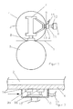
- the grinding head 10 of the grinding device 6 is force-controlled by a pressing element 12 against the outer circumferential surface of the roll shell 4.
- the grinding device 6 is arranged here in the 3 o'clock position of the roll mantle 4.
- the actuator 13 as well as the contact pressure element 8 are supported on the support 7 of the shoe press roll 3.
- the grinding device 6 is arranged axially traversable along the roll shell 4.
- the roll shell 4 Since the grinding surfaces 9 are fixed here in the form of a grid screen, the roll shell 4 must be driven at least during grinding.
- the rotation is to be chosen so that the speed of the outer circumferential surface of the roll shell 4 is between 800 and 1500 m / min.
Abstract
Description
Die Erfindung betrifft eine Anordnung zum Schleifen der Mantelaußenfläche einer Schuhpresswalze einer Maschine zur Herstellung und/oder Veredlung einer Papier-, Karton- oder einer anderen Faserstoffbahn, wobei die Schuhpresswalze einen flexiblen Walzenmantel besitzt, welcher von einem Anpresselement mit konkaver Pressfläche zu einer Gegenwalze gedrückt wird.The invention relates to an arrangement for grinding the outer shell surface of a shoe press roll of a machine for producing and / or finishing a paper, cardboard or other fibrous web, wherein the shoe press roll has a flexible roll shell, which is pressed by a pressing element with concave pressing surface to a counter roll ,
In den letzten Jahren wurden zunehmend auch Schuhpresswalzen zur Glättung von Faserstoffbahnen eingesetzt. Dabei werden, wie bei der Entwässerung der Faserstoffbahn, Walzenmäntel aus polymeren Werkstoffen verwendet.In recent years, shoe press rolls have been increasingly used for smoothing fibrous webs. In this case, as in the dewatering of the fibrous web, roll shells made of polymeric materials used.
Für das Erreichen eines guten Glättergebnisses ist die Oberflächenqualität des Walzenmantels von entscheidender Bedeutung.To achieve a good smoothing result, the surface quality of the roll mantle is of crucial importance.
Im Betrieb kann es jedoch vorkommen, dass Walzenmäntel über die Bahnbreite ungleichmäßig verschleißen, beispielsweise durch abrasive Füllstoffe in der Faserstoffbahn. Dies kann im weiteren Verlauf zu einem ungleichmäßigen Satinageergebnis hinsichtlich Glanz und Glätte führen.In operation, however, it may happen that roll shells wear unevenly over the web width, for example, by abrasive fillers in the fibrous web. This can lead to a non-uniform calendering result in terms of gloss and smoothness in the further course.
Überschreitet der ungleichmäßige Verschleiß ein bestimmtes Niveau, so muss gegenwärtig der Walzenmantel durch einen Neuen ersetzt werden, was kosten- und zeitintensiv ist.If the uneven wear exceeds a certain level, it is currently necessary to replace the roll shell with a new one, which is costly and time-consuming.
Die Aufgabe der Erfindung ist es daher, die Lebensdauer des Walzenmantels mit möglichst einfachen Mitteln und bei Gewährleistung einer möglichst hohen Glättwirkung zu verlängern.The object of the invention is therefore to extend the life of the roll shell with the simplest possible means and while ensuring the highest possible smoothing effect.
Erfindungsgemäß wurde die Aufgabe dadurch gelöst, dass wenigstens eine Schleifvorrichtung mit einer, mit der Mantelaußenfläche in Kontakt kommenden Schleiffläche axial an der Mantelaußenfläche traversierbar ist und sich der Walzenmantel auf der Innenseite gegenüber der Schleiffläche an einer Stützleiste abstützt.According to the invention, this object is achieved in that at least one grinding device with a, with the outer shell surface coming into contact grinding surface is axially traversable on the outer shell surface and the Roll shell on the inside opposite the grinding surface supported on a support bar.
Auf diese Weise kann der Walzenmantel in der Maschine geschliffen werden. Dies verlängert die Lebensdauer und macht einen Ausbau des Walzenmantels überflüssig.In this way, the roll shell can be ground in the machine. This extends the life and makes disassembly of the roll shell unnecessary.
Während die Traversierbarkeit der Schleifvorrichtung den Aufwand vermindert, ermöglicht die Abstützung des flexiblen Walzenmantels mit der Stützleiste erst das genaue Schleifen.While the traversability of the grinding device reduces the effort, the support of the flexible roll mantle with the support strip allows only the exact grinding.
Um über die Länge des Walzenmantels eine flexible Anpressung der Stützleiste zu ermöglichen, sollte die Stützleiste zumindest in radialer Richtung (bezüglich des Walzenmantels) flexibel ausgebildet sein. Hierzu kann die Stützleiste auch aus mehreren, axial nebeneinander angeordneten Elemente bestehen.In order to enable a flexible contact pressure of the support strip over the length of the roll mantle, the support strip should be designed to be flexible at least in the radial direction (with respect to the roll mantle). For this purpose, the support strip also consist of several axially juxtaposed elements.
Dabei sollte die Stützleiste vorzugsweise über pneumatische Stellglieder an die Innenseite des Walzenmantels anpressbar sein. Die flexible Anpressung, insbesondere mit Druckluft, soll eine Überpressung des Walzenmantels bzw. ein Festklemmen des Walzenmantels zwischen Stützleiste und Schleiffläche verhindern.The support strip should preferably be pressed by pneumatic actuators to the inside of the roll shell. The flexible contact pressure, in particular with compressed air, is intended to prevent an overpressing of the roll mantle or a clamping of the roll mantle between the support strip and the grinding surface.
Wegen der Flexibilität des Walzenmantels und zur Intensivierung der Schleifwirkung sollte die Schleiffläche an die Mantelaußenfläche anpressbar sein, was wegen der Stützleiste möglich ist. Dabei sollte der Anpressdruck zwischen 5 und 50 kPa, vorzugsweise zwischen 10 und 30 kPa liegen.Because of the flexibility of the roll shell and to intensify the abrasive effect, the grinding surface should be pressed against the shell outer surface, which is possible because of the support strip. The contact pressure should be between 5 and 50 kPa, preferably between 10 and 30 kPa.
Diese Anpressung der Schleiffläche kann weggesteuert oder kraftgesteuert erfolgen. Insbesondere die kraftgesteuerte Anpressung ist jedoch für einen gleichmäßigen Abtrag während des Schleifens von Vorteil.This contact pressure of the grinding surface can be controlled away or force controlled. In particular, the force-controlled contact pressure is advantageous for a uniform removal during grinding.
Damit sich die Durchbiegung des Walzenmantels auf Grund des Eigengewichts möglichst wenig auf das Schleifergebnis auswirkt, sollte die Schleifvorrichtung in der 3 oder 9 Uhr-Position des Walzenmantels angeordnet sein.So that the deflection of the roll shell due to its own weight has as little effect on the grinding result, the grinding device should be arranged in the 3 or 9 o'clock position of the roll shell.
Dabei kann die Schleiffläche von zumindest einem rotierenden Schleifelement, beispielsweise einem Schleifstein oder einem Schleifband, gebildet werden.In this case, the grinding surface can be formed by at least one rotating grinding element, for example a grinding stone or a grinding belt.
Vorzugsweise sollte die Schleiffläche jedoch von wenigstens einem statischen Schleifelement, vorzugsweise einer Gitterleinwand gebildet werden. Vorteilhaft kann aber auch ein quasi-statisches Schleifelement in Form eines Schleifbandes sein, welches zur Gewährleistung einer möglichst gleichbleibenden Schleifschärfe sehr langsam, vorzugsweise kontinuierlich aufgewickelt wird.Preferably, however, the abrasive surface should be formed by at least one static abrasive element, preferably a grid screen. However, a quasi-static grinding element in the form of an abrasive belt may also be advantageous, which is wound up very slowly, preferably continuously, in order to ensure as uniform a grinding sharpness as possible.
Zur Gewährleistung einer ausreichend hohen Relativgeschwindigkeit zwischen dem statischen Schleifelement und Walzenmantel muss jedoch der Walzenmantel zumindest während des Schleifens von einem Antrieb in Rotation versetzt werden.To ensure a sufficiently high relative speed between the static grinding element and the roll shell, however, the roll shell must be set in rotation at least during grinding by a drive.
Der dafür nötige Antrieb sollte im Interesse der Kompaktheit innerhalb des Walzenmantels angeordnet werden. Eine optimale Schleifwirkung ergibt sich dabei, wenn die Geschwindigkeit der Mantelaußenfläche während des Schleifens zwischen 500 und 2000 m/min, vorzugsweise zwischen 800 und 1500 m/min liegt.The necessary drive should be arranged in the interest of compactness within the roll shell. An optimal grinding effect results when the speed of the outer shell surface during grinding between 500 and 2000 m / min, preferably between 800 and 1500 m / min.
Für das Erreichen der erforderlichen Oberflächengüte des Walzenmantels sollte dieser erst mit einer relativ rauen und danach mit einer feineren Schleiffläche bearbeitet werden. Dies kann in zwei Durchgängen mit verschiedenen Schleifflächen oder mit mehreren Schleifvorrichtungen erfolgen.To achieve the required surface quality of the roll shell this should be processed first with a relatively rough and then with a finer grinding surface. This can be done in two passes with different sanding surfaces or with multiple sanders.
Jedoch ist es von Vorteil, wenn die Schleifvorrichtung zumindest zwei Schleifflächen unterschiedlicher Rauhigkeit besitzt. Auf diese Weise kann von der gleichen Schleifvorrichtung eine Bearbeitung mit der rauen und der feinen Schleiffläche ohne Umrüsten ausgehen.However, it is advantageous if the grinding device has at least two grinding surfaces of different roughness. In this way, machining with the rough and the fine grinding surface without conversion can start from the same grinding device.
Dabei sollte die mittlere Rautiefe der Schleifflächen zwischen 0,1 und 1 µm, vorzugsweise zwischen 0,5 und 0,7 µm liegen.The average surface roughness of the grinding surfaces should be between 0.1 and 1 .mu.m, preferably between 0.5 and 0.7 .mu.m.
Unabhängig davon, ob das Schleifen mit einem oder mehreren Schleifvorrichtungen erfolgt, sollte die Außenmantelfläche jedoch mit Schleifflächen mit Körnungsstufen von 80, 120, 220 und 400 nacheinander bearbeitet werden.Regardless of whether the grinding is done with one or more sanding devices, the outer surface should be machined one after another with sanding surfaces with grit levels of 80, 120, 220 and 400.
Zur Gewährleistung einer möglichst hohen Glätte der Außenmantelfläche sollte eine Verschmutzung vermieden werden. Daher sollte die Schleifvorrichtung eine Abführeinrichtung zum Entfernen der Schleifstäube, vorzugsweise in Form einer Absaugeinrichtung besitzen.To ensure the highest possible smoothness of the outer surface area contamination should be avoided. Therefore, the grinding device should have a discharge device for removing the grinding dust, preferably in the form of a suction device.
Außerdem ist es vorteilhaft, wenn die Schleifvorrichtung eine Kühleinrichtung für den Walzenmantel besitzt. Da der aus Kunststoff bestehende, flexible Walzenmantel relativ wärmeempfindlich ist, sollte die durch das Schleifen entstehende Wärme abführt werden, wobei die Kühlung vorzugsweise mit Luft oder einem Fluid erfolgen sollte.Moreover, it is advantageous if the grinding device has a cooling device for the roll shell. Since the existing plastic, flexible roll shell is relatively sensitive to heat, the heat generated by the grinding should be dissipated, the cooling should preferably be done with air or a fluid.
Nachfolgend soll die Erfindung an einem Ausführungsbeispiel näher erläutert werden. In der beigefügten Zeichnung zeigt:
- Figur 1:
- einen schematischen Querschnitt durch eine Glättanordnung und
- Figur 2:
- einen Teilschnitt durch die Schleifvorrichtung 6.
- FIG. 1:
- a schematic cross section through a smoothing arrangement and
- FIG. 2:
- a partial section through the grinding device. 6
Zur Glättung wird die Faserstoffbahn 1 gemäß
Dabei besteht die Schuhpresswalze 3 einen flexiblen Walzenmantel 4, der von einem hydraulischen Anpresselement 8 mit konkaver Pressfläche zur Gegenwalze 5 hin gedrückt wird. Durch die konkave Pressfläche kommt es zur Bildung eines verlängerten Glättspaltes, was eine intensive, aber volumenschonende Glättung ermöglicht.Here, the shoe press roll 3 is a flexible roll shell 4, which is pressed by a
Da die erreichbare Glätte bei der Faserstoffbahn 1 wesentlich von der Glätte der Außenmantelfläche des Walzenmantels 4 abhängt, wird diese bei Bedarf von einer Schleifvorrichtung 6 glatt geschliffen.Since the achievable smoothness in the
Hierzu wird der Schleifkopf 10 der Schleifvorrichtung 6 von einem Presselement 12 kraftgesteuert gegen die Außenmantelfläche des Walzenmantels 4 gedrückt. Damit die Durchbiegung des Walzenmantels 4 das Schleifergebnis möglichst wenig beeinflusst, ist die Schleifvorrichtung 6 hier in der 3 Uhr-Position des Walzenmantels 4 angeordnet.For this purpose, the grinding
Wegen der Flexibilität des Walzenmantels 4 stützt sich dieser an der Innenseite gegenüber dem Schleifkopf 10 auf einer Stützleiste 2 ab. Diese Stützleiste 2 besteht aus flexiblem Material und wird von einem pneumatischen Stellglied 13 über die Länge des Walzenmantels 4 flexibel zum Schleifkopf 10 gedrückt.Because of the flexibility of the roll shell 4, this is supported on the inside opposite the grinding
Das Stellglied 13 wie auch das Anpresselement 8 stützen sich am Träger 7 der Schuhpresswalze 3 ab.The
Die Schleifvorrichtung 6 ist axial entlang dem Walzenmantel 4 traversierbar angeordnet.The grinding device 6 is arranged axially traversable along the roll shell 4.
Bei der in
Wenn, wie in
Unabhängig von der Art und Anzahl der Schleifflächen 9 sollte der Schleifkopf 10 den Raum mit den Schleifflächen 9 gegenüber der Umgebung abgrenzen, was durch elastische Dichtungen 14 zwischen dem Schleifkopf 10 und dem Walzenmantel 4 noch verbessert werden kann.Regardless of the type and number of grinding surfaces 9, the grinding
Da die Schleifflächen 9 hier in Form einer Gitterleinwand feststehend sind, muss der Walzenmantel 4 zumindest während des Schleifens angetrieben werden. Dabei ist die Rotation so zu wählen, dass die Geschwindigkeit der Außenmantelfläche des Walzenmantels 4 zwischen 800 und 1500 m/min liegt.Since the grinding surfaces 9 are fixed here in the form of a grid screen, the roll shell 4 must be driven at least during grinding. The rotation is to be chosen so that the speed of the outer circumferential surface of the roll shell 4 is between 800 and 1500 m / min.
Die mittlere Rautiefe der Schleifflächen 9 beträgt zwischen 0,5 und 0,7 µm.
Der Schleifkopf 10 ist des Weiteren über einen Anschluss 11 mit einer Saugeinrichtung verbunden. Deren Unterdruck bewirkt die Absaugung der Schleifstäube und der vom Schleifen erwärmten Luft.The mean roughness of the grinding surfaces 9 is between 0.5 and 0.7 microns.
The grinding
Claims (12)
wenigstens eine Schleifvorrichtung (6) mit einer, mit der Mantelaußenfläche in Kontakt kommenden Schleiffläche (9) axial an der Mantelaußenfläche traversierbar ist und sich der Walzenmantel (4) auf der Innenseite gegenüber der Schleiffläche (9) an einer Stützleiste (2) abstützt.Arrangement for grinding the outer shell surface of a shoe press roll (3) of a machine for producing and / or finishing a paper, cardboard or other fibrous web (1), wherein the shoe press roll (3) has a flexible roll shell (4), which of a pressing element (8) is pressed with concave pressing surface to a counter-roller (5), characterized in that
at least one grinding device (6) having a grinding surface (9) which comes into contact with the casing outer surface is axially traversable on the casing outer surface and the roll casing (4) is supported on the inside against the grinding surface (9) on a support strip (2).
die Stützleiste (2) zumindest in radialer Richtung flexibel ausgebildet ist.Arrangement according to claim 1, characterized in that
the support strip (2) is flexible at least in the radial direction.
die Stützleiste (2) vorzugsweise über pneumatische Stellglieder (13) an die Innenseite des Walzenmantels (4) anpressbar ist.Arrangement according to claim 1 or 2, characterized in that
the support strip (2) preferably via pneumatic actuators (13) to the inside of the roll shell (4) can be pressed.
die Schleiffläche (9) an die Mantelaußenfläche anpressbar ist.Arrangement according to one of the preceding claims, characterized in that
the grinding surface (9) can be pressed against the casing outer surface.
die Anpressung kraftgesteuert erfolgt.Arrangement according to claim 4, characterized in that
the contact pressure is force-controlled.
die Schleifvorrichtung (6) in der 3 oder 9 Uhr-Position des Walzenmantels (4) angeordnet ist.Arrangement according to one of the preceding claims, characterized in that
the grinding device (6) is arranged in the 3 or 9 o'clock position of the roll mantle (4).
die Schleiffläche (9) von zumindest einem rotierenden Schleifelement gebildet wird.Arrangement according to one of the preceding claims, characterized in that
the grinding surface (9) is formed by at least one rotating grinding element.
die Schleiffläche (9) von wenigstens einem statischen Schleifelement gebildet wird und der Walzenmantel (4) einen vorzugsweise innen liegenden Antrieb besitzt.Arrangement according to one of the preceding claims, characterized in that
the grinding surface (9) is formed by at least one static grinding element and the roll mantle (4) has a preferably internal drive.
die Geschwindigkeit der Mantelaußenfläche während des Schleifens zwischen 500 und 2000 m/min, vorzugsweise zwischen 800 und 1500 m/min liegt.Arrangement according to claim 8, characterized in that
the speed of the outer shell surface during grinding is between 500 and 2000 m / min, preferably between 800 and 1500 m / min.
die Schleifvorrichtung (6) zumindest zwei Schleifflächen (9) unterschiedlicher Rauhigkeit besitzt.Arrangement according to one of the preceding claims, characterized in that
the grinding device (6) has at least two grinding surfaces (9) of different roughness.
die mittlere Rautiefe der Schleifflächen zwischen 0,1 und 1 µm, vorzugsweise zwischen 0,5 und 0,7 µm liegt.Arrangement according to one of the preceding claims, characterized in that
the average surface roughness of the grinding surfaces is between 0.1 and 1 μm, preferably between 0.5 and 0.7 μm.
die Schleifvorrichtung (6) eine Abführeinrichtung zum Entfernen der Schleifstäube, vorzugsweise in Form einer Absaugeinrichtung besitzt.Arrangement according to one of the preceding claims, characterized in that
the grinding device (6) has a discharge device for removing the grinding dust, preferably in the form of a suction device.
Priority Applications (1)
| Application Number | Priority Date | Filing Date | Title |
|---|---|---|---|
| PL08150994T PL1997584T3 (en) | 2007-05-26 | 2008-02-04 | Grinding assembly |
Applications Claiming Priority (1)
| Application Number | Priority Date | Filing Date | Title |
|---|---|---|---|
| DE102007024810A DE102007024810A1 (en) | 2007-05-26 | 2007-05-26 | grinding system |
Publications (3)
| Publication Number | Publication Date |
|---|---|
| EP1997584A2 true EP1997584A2 (en) | 2008-12-03 |
| EP1997584A3 EP1997584A3 (en) | 2009-03-04 |
| EP1997584B1 EP1997584B1 (en) | 2010-05-05 |
Family
ID=39577864
Family Applications (1)
| Application Number | Title | Priority Date | Filing Date |
|---|---|---|---|
| EP08150994A Not-in-force EP1997584B1 (en) | 2007-05-26 | 2008-02-04 | Grinding assembly |
Country Status (4)
| Country | Link |
|---|---|
| EP (1) | EP1997584B1 (en) |
| AT (1) | ATE466689T1 (en) |
| DE (2) | DE102007024810A1 (en) |
| PL (1) | PL1997584T3 (en) |
Cited By (1)
| Publication number | Priority date | Publication date | Assignee | Title |
|---|---|---|---|---|
| CN103949476A (en) * | 2014-04-24 | 2014-07-30 | 邯钢集团邯宝钢铁有限公司 | Method for fast predicting grinding quantity of support roller of hot rolled plate strip rolling mill |
Families Citing this family (1)
| Publication number | Priority date | Publication date | Assignee | Title |
|---|---|---|---|---|
| CN103358197A (en) * | 2013-07-22 | 2013-10-23 | 天长市天力液压机械有限责任公司 | Rubber roll grinding machine |
Citations (4)
| Publication number | Priority date | Publication date | Assignee | Title |
|---|---|---|---|---|
| US4518460A (en) * | 1981-01-27 | 1985-05-21 | J.M. Voith Gmbh | Press roll for web material |
| DE29915022U1 (en) * | 1999-08-27 | 1999-10-21 | Schmoetzer Hubert | Device for the material-removing processing of the lateral surface of cylindrical rollers of a printing press |
| EP1316643A2 (en) * | 2001-11-12 | 2003-06-04 | Mitsubishi Heavy Industries, Ltd. | Calender for a sheet of paper |
| WO2006134234A2 (en) * | 2005-06-17 | 2006-12-21 | Metso Paper, Inc. | Method for grinding a variable crown roll |
-
2007
- 2007-05-26 DE DE102007024810A patent/DE102007024810A1/en not_active Withdrawn
-
2008
- 2008-02-04 PL PL08150994T patent/PL1997584T3/en unknown
- 2008-02-04 EP EP08150994A patent/EP1997584B1/en not_active Not-in-force
- 2008-02-04 DE DE502008000609T patent/DE502008000609D1/en active Active
- 2008-02-04 AT AT08150994T patent/ATE466689T1/en active
Patent Citations (4)
| Publication number | Priority date | Publication date | Assignee | Title |
|---|---|---|---|---|
| US4518460A (en) * | 1981-01-27 | 1985-05-21 | J.M. Voith Gmbh | Press roll for web material |
| DE29915022U1 (en) * | 1999-08-27 | 1999-10-21 | Schmoetzer Hubert | Device for the material-removing processing of the lateral surface of cylindrical rollers of a printing press |
| EP1316643A2 (en) * | 2001-11-12 | 2003-06-04 | Mitsubishi Heavy Industries, Ltd. | Calender for a sheet of paper |
| WO2006134234A2 (en) * | 2005-06-17 | 2006-12-21 | Metso Paper, Inc. | Method for grinding a variable crown roll |
Cited By (1)
| Publication number | Priority date | Publication date | Assignee | Title |
|---|---|---|---|---|
| CN103949476A (en) * | 2014-04-24 | 2014-07-30 | 邯钢集团邯宝钢铁有限公司 | Method for fast predicting grinding quantity of support roller of hot rolled plate strip rolling mill |
Also Published As
| Publication number | Publication date |
|---|---|
| ATE466689T1 (en) | 2010-05-15 |
| DE502008000609D1 (en) | 2010-06-17 |
| EP1997584A3 (en) | 2009-03-04 |
| DE102007024810A1 (en) | 2008-11-27 |
| PL1997584T3 (en) | 2010-10-29 |
| EP1997584B1 (en) | 2010-05-05 |
Similar Documents
| Publication | Publication Date | Title |
|---|---|---|
| EP0405185B1 (en) | Apparatus for roughing a laminate surface | |
| DE3805350C2 (en) | ||
| EP1997584B1 (en) | Grinding assembly | |
| DE4026021C2 (en) | Press section of a paper machine | |
| EP0273093B1 (en) | Process and apparatus for making a non-elastic, impervious and flexible pressure belt, particularly for the wet press of a paper-making machine | |
| EP3891333B1 (en) | Roll and method for producing a roll | |
| WO2002051585A2 (en) | Device for grinding an external sleeve surface | |
| EP1146152B1 (en) | Support disc with a caouchouc ring for a disc bearing holding a spinning rotor | |
| EP0826819B1 (en) | Apparatus for dewatering a fibre suspension | |
| DE2713464B2 (en) | Device for the production of corrugated cardboard | |
| DE10115670C1 (en) | Device for cleaning the surface (s) of a moving material web | |
| EP0400573A1 (en) | Method and apparatus for the manufacture of an endless belt coated on both sides | |
| EP4204625A1 (en) | Control of a fibre treatment device | |
| EP1362950A1 (en) | Process and apparatus for dewatering a fibrous web | |
| EP1837438A2 (en) | Machine for manufacturing sheet material, in particular paper or cardboard, and method for treating the surface of a conveyor belt in a machine for producing sheet material | |
| DE10239402B4 (en) | Roller grinding apparatus and method for grinding a roller | |
| EP1870514A2 (en) | Conveyor belt for a machine for the production of sheet material and method for the production of such a conveyor belt | |
| WO2011098284A2 (en) | Method and device for applying a surface layer to a roller and use of said method and device | |
| DE19654194B4 (en) | Endless press cover for a pressing device | |
| EP0779391B1 (en) | Method for milling paper fibres | |
| EP4110552B1 (en) | Polishing tool | |
| DE3515265C2 (en) | ||
| DE102005000094A1 (en) | Winding core for sheet of fibrous material, e.g. paper, comprises drum with casing having openings for application of reduced pressure to core interior to guide initial strip of sheet efficiently onto core | |
| DE212016000259U1 (en) | Press belt, arrangement in a long nip and production system of a press belt | |
| EP4305237A1 (en) | Doctor blade and roll device |
Legal Events
| Date | Code | Title | Description |
|---|---|---|---|
| PUAI | Public reference made under article 153(3) epc to a published international application that has entered the european phase |
Free format text: ORIGINAL CODE: 0009012 |
|
| AK | Designated contracting states |
Kind code of ref document: A2 Designated state(s): AT BE BG CH CY CZ DE DK EE ES FI FR GB GR HR HU IE IS IT LI LT LU LV MC MT NL NO PL PT RO SE SI SK TR |
|
| AX | Request for extension of the european patent |
Extension state: AL BA MK RS |
|
| PUAL | Search report despatched |
Free format text: ORIGINAL CODE: 0009013 |
|
| AK | Designated contracting states |
Kind code of ref document: A3 Designated state(s): AT BE BG CH CY CZ DE DK EE ES FI FR GB GR HR HU IE IS IT LI LT LU LV MC MT NL NO PL PT RO SE SI SK TR |
|
| AX | Request for extension of the european patent |
Extension state: AL BA MK RS |
|
| 17P | Request for examination filed |
Effective date: 20090904 |
|
| AKX | Designation fees paid |
Designated state(s): AT BE BG CH CY CZ DE DK EE ES FI FR GB GR HR HU IE IS IT LI LT LU LV MC MT NL NO PL PT RO SE SI SK TR |
|
| GRAP | Despatch of communication of intention to grant a patent |
Free format text: ORIGINAL CODE: EPIDOSNIGR1 |
|
| GRAS | Grant fee paid |
Free format text: ORIGINAL CODE: EPIDOSNIGR3 |
|
| GRAA | (expected) grant |
Free format text: ORIGINAL CODE: 0009210 |
|
| AK | Designated contracting states |
Kind code of ref document: B1 Designated state(s): AT BE BG CH CY CZ DE DK EE ES FI FR GB GR HR HU IE IS IT LI LT LU LV MC MT NL NO PL PT RO SE SI SK TR |
|
| REG | Reference to a national code |
Ref country code: GB Ref legal event code: FG4D Free format text: NOT ENGLISH |
|
| REG | Reference to a national code |
Ref country code: CH Ref legal event code: EP |
|
| REG | Reference to a national code |
Ref country code: IE Ref legal event code: FG4D Free format text: LANGUAGE OF EP DOCUMENT: GERMAN |
|
| REF | Corresponds to: |
Ref document number: 502008000609 Country of ref document: DE Date of ref document: 20100617 Kind code of ref document: P |
|
| REG | Reference to a national code |
Ref country code: SE Ref legal event code: TRGR |
|
| REG | Reference to a national code |
Ref country code: NL Ref legal event code: VDEP Effective date: 20100505 |
|
| LTIE | Lt: invalidation of european patent or patent extension |
Effective date: 20100505 |
|
| PG25 | Lapsed in a contracting state [announced via postgrant information from national office to epo] |
Ref country code: ES Free format text: LAPSE BECAUSE OF FAILURE TO SUBMIT A TRANSLATION OF THE DESCRIPTION OR TO PAY THE FEE WITHIN THE PRESCRIBED TIME-LIMIT Effective date: 20100816 Ref country code: NO Free format text: LAPSE BECAUSE OF FAILURE TO SUBMIT A TRANSLATION OF THE DESCRIPTION OR TO PAY THE FEE WITHIN THE PRESCRIBED TIME-LIMIT Effective date: 20100805 Ref country code: NL Free format text: LAPSE BECAUSE OF FAILURE TO SUBMIT A TRANSLATION OF THE DESCRIPTION OR TO PAY THE FEE WITHIN THE PRESCRIBED TIME-LIMIT Effective date: 20100505 Ref country code: LT Free format text: LAPSE BECAUSE OF FAILURE TO SUBMIT A TRANSLATION OF THE DESCRIPTION OR TO PAY THE FEE WITHIN THE PRESCRIBED TIME-LIMIT Effective date: 20100505 |
|
| REG | Reference to a national code |
Ref country code: PL Ref legal event code: T3 |
|
| PG25 | Lapsed in a contracting state [announced via postgrant information from national office to epo] |
Ref country code: IS Free format text: LAPSE BECAUSE OF FAILURE TO SUBMIT A TRANSLATION OF THE DESCRIPTION OR TO PAY THE FEE WITHIN THE PRESCRIBED TIME-LIMIT Effective date: 20100905 Ref country code: HR Free format text: LAPSE BECAUSE OF FAILURE TO SUBMIT A TRANSLATION OF THE DESCRIPTION OR TO PAY THE FEE WITHIN THE PRESCRIBED TIME-LIMIT Effective date: 20100505 Ref country code: SI Free format text: LAPSE BECAUSE OF FAILURE TO SUBMIT A TRANSLATION OF THE DESCRIPTION OR TO PAY THE FEE WITHIN THE PRESCRIBED TIME-LIMIT Effective date: 20100505 Ref country code: LV Free format text: LAPSE BECAUSE OF FAILURE TO SUBMIT A TRANSLATION OF THE DESCRIPTION OR TO PAY THE FEE WITHIN THE PRESCRIBED TIME-LIMIT Effective date: 20100505 |
|
| REG | Reference to a national code |
Ref country code: IE Ref legal event code: FD4D |
|
| PG25 | Lapsed in a contracting state [announced via postgrant information from national office to epo] |
Ref country code: CY Free format text: LAPSE BECAUSE OF FAILURE TO SUBMIT A TRANSLATION OF THE DESCRIPTION OR TO PAY THE FEE WITHIN THE PRESCRIBED TIME-LIMIT Effective date: 20100602 |
|
| PG25 | Lapsed in a contracting state [announced via postgrant information from national office to epo] |
Ref country code: IE Free format text: LAPSE BECAUSE OF FAILURE TO SUBMIT A TRANSLATION OF THE DESCRIPTION OR TO PAY THE FEE WITHIN THE PRESCRIBED TIME-LIMIT Effective date: 20100505 Ref country code: EE Free format text: LAPSE BECAUSE OF FAILURE TO SUBMIT A TRANSLATION OF THE DESCRIPTION OR TO PAY THE FEE WITHIN THE PRESCRIBED TIME-LIMIT Effective date: 20100505 Ref country code: DK Free format text: LAPSE BECAUSE OF FAILURE TO SUBMIT A TRANSLATION OF THE DESCRIPTION OR TO PAY THE FEE WITHIN THE PRESCRIBED TIME-LIMIT Effective date: 20100505 |
|
| PG25 | Lapsed in a contracting state [announced via postgrant information from national office to epo] |
Ref country code: CZ Free format text: LAPSE BECAUSE OF FAILURE TO SUBMIT A TRANSLATION OF THE DESCRIPTION OR TO PAY THE FEE WITHIN THE PRESCRIBED TIME-LIMIT Effective date: 20100505 Ref country code: SK Free format text: LAPSE BECAUSE OF FAILURE TO SUBMIT A TRANSLATION OF THE DESCRIPTION OR TO PAY THE FEE WITHIN THE PRESCRIBED TIME-LIMIT Effective date: 20100505 Ref country code: RO Free format text: LAPSE BECAUSE OF FAILURE TO SUBMIT A TRANSLATION OF THE DESCRIPTION OR TO PAY THE FEE WITHIN THE PRESCRIBED TIME-LIMIT Effective date: 20100505 |
|
| PLBE | No opposition filed within time limit |
Free format text: ORIGINAL CODE: 0009261 |
|
| STAA | Information on the status of an ep patent application or granted ep patent |
Free format text: STATUS: NO OPPOSITION FILED WITHIN TIME LIMIT |
|
| 26N | No opposition filed |
Effective date: 20110208 |
|
| REG | Reference to a national code |
Ref country code: DE Ref legal event code: R097 Ref document number: 502008000609 Country of ref document: DE Effective date: 20110207 |
|
| PG25 | Lapsed in a contracting state [announced via postgrant information from national office to epo] |
Ref country code: GR Free format text: LAPSE BECAUSE OF FAILURE TO SUBMIT A TRANSLATION OF THE DESCRIPTION OR TO PAY THE FEE WITHIN THE PRESCRIBED TIME-LIMIT Effective date: 20100806 |
|
| PGFP | Annual fee paid to national office [announced via postgrant information from national office to epo] |
Ref country code: SE Payment date: 20110214 Year of fee payment: 4 Ref country code: PL Payment date: 20110124 Year of fee payment: 4 Ref country code: FR Payment date: 20110302 Year of fee payment: 4 Ref country code: DE Payment date: 20110218 Year of fee payment: 4 Ref country code: FI Payment date: 20110214 Year of fee payment: 4 |
|
| BERE | Be: lapsed |
Owner name: VOITH PATENT G.M.B.H. Effective date: 20110228 |
|
| PG25 | Lapsed in a contracting state [announced via postgrant information from national office to epo] |
Ref country code: MC Free format text: LAPSE BECAUSE OF NON-PAYMENT OF DUE FEES Effective date: 20110228 |
|
| PG25 | Lapsed in a contracting state [announced via postgrant information from national office to epo] |
Ref country code: BE Free format text: LAPSE BECAUSE OF NON-PAYMENT OF DUE FEES Effective date: 20110228 |
|
| PG25 | Lapsed in a contracting state [announced via postgrant information from national office to epo] |
Ref country code: MT Free format text: LAPSE BECAUSE OF FAILURE TO SUBMIT A TRANSLATION OF THE DESCRIPTION OR TO PAY THE FEE WITHIN THE PRESCRIBED TIME-LIMIT Effective date: 20100505 |
|
| PGFP | Annual fee paid to national office [announced via postgrant information from national office to epo] |
Ref country code: IT Payment date: 20110228 Year of fee payment: 4 |
|
| REG | Reference to a national code |
Ref country code: CH Ref legal event code: PL |
|
| GBPC | Gb: european patent ceased through non-payment of renewal fee |
Effective date: 20120204 |
|
| PG25 | Lapsed in a contracting state [announced via postgrant information from national office to epo] |
Ref country code: CH Free format text: LAPSE BECAUSE OF NON-PAYMENT OF DUE FEES Effective date: 20120229 Ref country code: SE Free format text: LAPSE BECAUSE OF NON-PAYMENT OF DUE FEES Effective date: 20120205 Ref country code: LI Free format text: LAPSE BECAUSE OF NON-PAYMENT OF DUE FEES Effective date: 20120229 Ref country code: FI Free format text: LAPSE BECAUSE OF NON-PAYMENT OF DUE FEES Effective date: 20120204 |
|
| REG | Reference to a national code |
Ref country code: FR Ref legal event code: ST Effective date: 20121031 |
|
| PG25 | Lapsed in a contracting state [announced via postgrant information from national office to epo] |
Ref country code: IT Free format text: LAPSE BECAUSE OF NON-PAYMENT OF DUE FEES Effective date: 20120204 |
|
| REG | Reference to a national code |
Ref country code: DE Ref legal event code: R119 Ref document number: 502008000609 Country of ref document: DE Effective date: 20120901 |
|
| PG25 | Lapsed in a contracting state [announced via postgrant information from national office to epo] |
Ref country code: GB Free format text: LAPSE BECAUSE OF NON-PAYMENT OF DUE FEES Effective date: 20120204 Ref country code: FR Free format text: LAPSE BECAUSE OF NON-PAYMENT OF DUE FEES Effective date: 20120229 |
|
| PG25 | Lapsed in a contracting state [announced via postgrant information from national office to epo] |
Ref country code: LU Free format text: LAPSE BECAUSE OF NON-PAYMENT OF DUE FEES Effective date: 20110204 |
|
| PG25 | Lapsed in a contracting state [announced via postgrant information from national office to epo] |
Ref country code: DE Free format text: LAPSE BECAUSE OF NON-PAYMENT OF DUE FEES Effective date: 20120901 |
|
| PG25 | Lapsed in a contracting state [announced via postgrant information from national office to epo] |
Ref country code: PT Free format text: LAPSE BECAUSE OF NON-PAYMENT OF DUE FEES Effective date: 20100505 |
|
| PG25 | Lapsed in a contracting state [announced via postgrant information from national office to epo] |
Ref country code: TR Free format text: LAPSE BECAUSE OF FAILURE TO SUBMIT A TRANSLATION OF THE DESCRIPTION OR TO PAY THE FEE WITHIN THE PRESCRIBED TIME-LIMIT Effective date: 20100505 Ref country code: BG Free format text: LAPSE BECAUSE OF FAILURE TO SUBMIT A TRANSLATION OF THE DESCRIPTION OR TO PAY THE FEE WITHIN THE PRESCRIBED TIME-LIMIT Effective date: 20100805 |
|
| PG25 | Lapsed in a contracting state [announced via postgrant information from national office to epo] |
Ref country code: HU Free format text: LAPSE BECAUSE OF FAILURE TO SUBMIT A TRANSLATION OF THE DESCRIPTION OR TO PAY THE FEE WITHIN THE PRESCRIBED TIME-LIMIT Effective date: 20100505 |
|
| REG | Reference to a national code |
Ref country code: AT Ref legal event code: MM01 Ref document number: 466689 Country of ref document: AT Kind code of ref document: T Effective date: 20130204 |
|
| PG25 | Lapsed in a contracting state [announced via postgrant information from national office to epo] |
Ref country code: AT Free format text: LAPSE BECAUSE OF NON-PAYMENT OF DUE FEES Effective date: 20130204 Ref country code: PL Free format text: LAPSE BECAUSE OF NON-PAYMENT OF DUE FEES Effective date: 20130204 |
|
| REG | Reference to a national code |
Ref country code: PL Ref legal event code: LAPE |