EP1997773A2 - Improved electrochemical hydrogen storage alloys for nickel metal hydride batteries - Google Patents
Improved electrochemical hydrogen storage alloys for nickel metal hydride batteries Download PDFInfo
- Publication number
- EP1997773A2 EP1997773A2 EP08151625A EP08151625A EP1997773A2 EP 1997773 A2 EP1997773 A2 EP 1997773A2 EP 08151625 A EP08151625 A EP 08151625A EP 08151625 A EP08151625 A EP 08151625A EP 1997773 A2 EP1997773 A2 EP 1997773A2
- Authority
- EP
- European Patent Office
- Prior art keywords
- alloys
- alloy
- atomic percent
- materials
- hydrogen storage
- Prior art date
- Legal status (The legal status is an assumption and is not a legal conclusion. Google has not performed a legal analysis and makes no representation as to the accuracy of the status listed.)
- Withdrawn
Links
Images
Classifications
-
- H—ELECTRICITY
- H01—ELECTRIC ELEMENTS
- H01M—PROCESSES OR MEANS, e.g. BATTERIES, FOR THE DIRECT CONVERSION OF CHEMICAL ENERGY INTO ELECTRICAL ENERGY
- H01M4/00—Electrodes
- H01M4/02—Electrodes composed of, or comprising, active material
- H01M4/36—Selection of substances as active materials, active masses, active liquids
- H01M4/38—Selection of substances as active materials, active masses, active liquids of elements or alloys
-
- C—CHEMISTRY; METALLURGY
- C22—METALLURGY; FERROUS OR NON-FERROUS ALLOYS; TREATMENT OF ALLOYS OR NON-FERROUS METALS
- C22C—ALLOYS
- C22C30/00—Alloys containing less than 50% by weight of each constituent
-
- C—CHEMISTRY; METALLURGY
- C01—INORGANIC CHEMISTRY
- C01B—NON-METALLIC ELEMENTS; COMPOUNDS THEREOF; METALLOIDS OR COMPOUNDS THEREOF NOT COVERED BY SUBCLASS C01C
- C01B3/00—Hydrogen; Gaseous mixtures containing hydrogen; Separation of hydrogen from mixtures containing it; Purification of hydrogen
- C01B3/0005—Reversible uptake of hydrogen by an appropriate medium, i.e. based on physical or chemical sorption phenomena or on reversible chemical reactions, e.g. for hydrogen storage purposes ; Reversible gettering of hydrogen; Reversible uptake of hydrogen by electrodes
- C01B3/001—Reversible uptake of hydrogen by an appropriate medium, i.e. based on physical or chemical sorption phenomena or on reversible chemical reactions, e.g. for hydrogen storage purposes ; Reversible gettering of hydrogen; Reversible uptake of hydrogen by electrodes characterised by the uptaking medium; Treatment thereof
- C01B3/0031—Intermetallic compounds; Metal alloys; Treatment thereof
- C01B3/0047—Intermetallic compounds; Metal alloys; Treatment thereof containing a rare earth metal; Treatment thereof
- C01B3/0057—Intermetallic compounds; Metal alloys; Treatment thereof containing a rare earth metal; Treatment thereof also containing nickel
-
- H—ELECTRICITY
- H01—ELECTRIC ELEMENTS
- H01M—PROCESSES OR MEANS, e.g. BATTERIES, FOR THE DIRECT CONVERSION OF CHEMICAL ENERGY INTO ELECTRICAL ENERGY
- H01M10/00—Secondary cells; Manufacture thereof
- H01M10/34—Gastight accumulators
- H01M10/345—Gastight metal hydride accumulators
-
- H—ELECTRICITY
- H01—ELECTRIC ELEMENTS
- H01M—PROCESSES OR MEANS, e.g. BATTERIES, FOR THE DIRECT CONVERSION OF CHEMICAL ENERGY INTO ELECTRICAL ENERGY
- H01M4/00—Electrodes
- H01M4/02—Electrodes composed of, or comprising, active material
- H01M4/04—Processes of manufacture in general
- H01M4/049—Manufacturing of an active layer by chemical means
-
- H—ELECTRICITY
- H01—ELECTRIC ELEMENTS
- H01M—PROCESSES OR MEANS, e.g. BATTERIES, FOR THE DIRECT CONVERSION OF CHEMICAL ENERGY INTO ELECTRICAL ENERGY
- H01M4/00—Electrodes
- H01M4/02—Electrodes composed of, or comprising, active material
- H01M4/36—Selection of substances as active materials, active masses, active liquids
- H01M4/362—Composites
- H01M4/366—Composites as layered products
-
- H—ELECTRICITY
- H01—ELECTRIC ELEMENTS
- H01M—PROCESSES OR MEANS, e.g. BATTERIES, FOR THE DIRECT CONVERSION OF CHEMICAL ENERGY INTO ELECTRICAL ENERGY
- H01M4/00—Electrodes
- H01M4/02—Electrodes composed of, or comprising, active material
- H01M4/36—Selection of substances as active materials, active masses, active liquids
- H01M4/38—Selection of substances as active materials, active masses, active liquids of elements or alloys
- H01M4/383—Hydrogen absorbing alloys
-
- H—ELECTRICITY
- H01—ELECTRIC ELEMENTS
- H01M—PROCESSES OR MEANS, e.g. BATTERIES, FOR THE DIRECT CONVERSION OF CHEMICAL ENERGY INTO ELECTRICAL ENERGY
- H01M4/00—Electrodes
- H01M4/02—Electrodes composed of, or comprising, active material
- H01M2004/021—Physical characteristics, e.g. porosity, surface area
-
- H—ELECTRICITY
- H01—ELECTRIC ELEMENTS
- H01M—PROCESSES OR MEANS, e.g. BATTERIES, FOR THE DIRECT CONVERSION OF CHEMICAL ENERGY INTO ELECTRICAL ENERGY
- H01M4/00—Electrodes
- H01M4/02—Electrodes composed of, or comprising, active material
- H01M4/36—Selection of substances as active materials, active masses, active liquids
- H01M4/38—Selection of substances as active materials, active masses, active liquids of elements or alloys
- H01M4/46—Alloys based on magnesium or aluminium
-
- Y—GENERAL TAGGING OF NEW TECHNOLOGICAL DEVELOPMENTS; GENERAL TAGGING OF CROSS-SECTIONAL TECHNOLOGIES SPANNING OVER SEVERAL SECTIONS OF THE IPC; TECHNICAL SUBJECTS COVERED BY FORMER USPC CROSS-REFERENCE ART COLLECTIONS [XRACs] AND DIGESTS
- Y02—TECHNOLOGIES OR APPLICATIONS FOR MITIGATION OR ADAPTATION AGAINST CLIMATE CHANGE
- Y02E—REDUCTION OF GREENHOUSE GAS [GHG] EMISSIONS, RELATED TO ENERGY GENERATION, TRANSMISSION OR DISTRIBUTION
- Y02E60/00—Enabling technologies; Technologies with a potential or indirect contribution to GHG emissions mitigation
- Y02E60/10—Energy storage using batteries
-
- Y—GENERAL TAGGING OF NEW TECHNOLOGICAL DEVELOPMENTS; GENERAL TAGGING OF CROSS-SECTIONAL TECHNOLOGIES SPANNING OVER SEVERAL SECTIONS OF THE IPC; TECHNICAL SUBJECTS COVERED BY FORMER USPC CROSS-REFERENCE ART COLLECTIONS [XRACs] AND DIGESTS
- Y02—TECHNOLOGIES OR APPLICATIONS FOR MITIGATION OR ADAPTATION AGAINST CLIMATE CHANGE
- Y02E—REDUCTION OF GREENHOUSE GAS [GHG] EMISSIONS, RELATED TO ENERGY GENERATION, TRANSMISSION OR DISTRIBUTION
- Y02E60/00—Enabling technologies; Technologies with a potential or indirect contribution to GHG emissions mitigation
- Y02E60/30—Hydrogen technology
- Y02E60/32—Hydrogen storage
-
- Y—GENERAL TAGGING OF NEW TECHNOLOGICAL DEVELOPMENTS; GENERAL TAGGING OF CROSS-SECTIONAL TECHNOLOGIES SPANNING OVER SEVERAL SECTIONS OF THE IPC; TECHNICAL SUBJECTS COVERED BY FORMER USPC CROSS-REFERENCE ART COLLECTIONS [XRACs] AND DIGESTS
- Y10—TECHNICAL SUBJECTS COVERED BY FORMER USPC
- Y10S—TECHNICAL SUBJECTS COVERED BY FORMER USPC CROSS-REFERENCE ART COLLECTIONS [XRACs] AND DIGESTS
- Y10S420/00—Alloys or metallic compositions
- Y10S420/90—Hydrogen storage
Landscapes
- Chemical & Material Sciences (AREA)
- Chemical Kinetics & Catalysis (AREA)
- General Chemical & Material Sciences (AREA)
- Engineering & Computer Science (AREA)
- Organic Chemistry (AREA)
- Electrochemistry (AREA)
- Combustion & Propulsion (AREA)
- Inorganic Chemistry (AREA)
- Composite Materials (AREA)
- Manufacturing & Machinery (AREA)
- Life Sciences & Earth Sciences (AREA)
- Environmental & Geological Engineering (AREA)
- Geology (AREA)
- General Life Sciences & Earth Sciences (AREA)
- Materials Engineering (AREA)
- Mechanical Engineering (AREA)
- Metallurgy (AREA)
- Battery Electrode And Active Subsutance (AREA)
- Secondary Cells (AREA)
- Powder Metallurgy (AREA)
Abstract
Description
- The present invention is a continuation in part of
U.S. Patent Application No. 08/136,066 filed October 14, 1993 U.S. Patent Application No. 08/136,066 is a continuation in part ofU.S. Patent No. 5,277,999 (filed asU.S. Patent Application No. 07/934,976 on August 25, 1992 U.S. Patent No. 5,277,999 is a continuation in part ofU.S. Patent No. 5,238,756 (filed asU.S. Patent Application No. 07/746,015 on August 14, 1991 U.S. Patent No. 5,238,756 is a continuation in part ofU.S. Patent No. 5,104,617 (filed asU.S. Patent Application No. 07/515,020 on April 26, 1990 - The present invention relates to electrochemical hydrogen storage alloys and rechargeable electrochemical cells using these alloys.
- More particularly, the invention relates to rechargeable cells and batteries having negative electrodes formed of multicomponent, electrochemical hydrogen storage alloys. Cells that incorporate these alloys have performance characteristics, such as energy density, charge retention, cycle life, and low temperature performance that are significantly improved over known rechargeable cells using hydrogen storage alloys. The present invention also describes unique alloys that utilize significantly reduced amounts of Co without a loss in performance.
- Rechargeable cells that use a nickel hydroxide positive electrode and a metal hydride forming hydrogen storage negative electrode ("metal hydride cells") are known in art. When an electrical potential is applied between the electrolyte and a metal hydride electrode in a metal hydride cell, the negative electrode material (M) is charged by the electrochemical absorption of hydrogen and the electrochemical evolution of a hydroxyl ion; upon discharge, the stored hydrogen is released to form a water molecule and evolve an electron:

- The reactions that take place at the positive electrode of a nickel metal hydride cell are also reversible. Most metal hydride cells use a nickel hydroxide positive electrode. The following charge and discharge reactions take place at a nickel hydroxide positive electrode:

- The first hydrogen storage alloys to be investigated as battery electrode materials were TiNi and LaNi5. Many years were spent in studying these simple binary intermetallics because they were known to have the proper hydrogen bond strength for use in electrochemical applications. Despite extensive efforts, however, researchers found these intermetallics to be extremely unstable and of marginal electrochemical value due to a variety of deleterious effects such as slow discharge, oxidation, corrosion, poor kinetics, and poor catalysis. These simple alloys for battery applications reflects the traditional bias of battery developers toward the use of single element couples of crystalline materials such as NiCd, NaS, LiMS, ZnBr, NiFe, NiZn, and Pb-acid. In order to improve the electrochemical properties of the binary intermetallics while maintaining the hydrogen storage efficiency, early workers began modifying TiNi and LaNi5 systems.
- The modification of TiNi and LaNi5 was initiated by Stanford R. Ovshinsky at Energy Conversion Devices (ECD) of Troy, Michigan. Ovshinsky and his team at ECD showed that reliance on simple, relatively pure compounds was a major shortcoming of the prior art. Prior work had determined that catalytic action depends on surface reactions at sites of irregularities in the crystal structure. Relatively pure compounds were found to have a relatively low density of hydrogen storage sites, and the type of sites available occurred accidently and were not designed into the bulk of the material. Thus, the efficiency of the storage of hydrogen and the subsequent release of hydrogen was determined to be substantially less than that which would be possible if a greater number and variety of active sites were available.
- Ovshinsky had previously found that the number of surface sites could be increased significantly by making an amorphous film that resembled the surface of the desired relatively pure materials. As Ovshinsky explained in Principles and Applications of Amorphicity, Structural Change, and Optical Information Encoding, 42 Journal De Physique at C4-1096 (Octobre 1981):
- Amorphicity is a generic term referring to lack of X-ray diffraction evidence of long-range periodicity and is not a sufficient description of a material. To understand amorphous materials, there are several important factors to be considered: the type of chemical bonding, the number of bonds generated by the local order, that is its coordination, and the influence of the entire local environment, both chemical and geometrical, upon the resulting varied configurations. Amorphicity is not determined by random packing of atoms viewed as hard spheres nor is the amorphous solid merely a host with atoms imbedded at random.
- Amorphous materials should be viewed as being composed of an interactive matrix whose electronic configurations are generated by free energy forces and they can be specifically defined by the chemical nature and coordination of the constituent atoms. Utilizing multi-orbital elements and various preparation techniques, one can outwit the normal relaxations that reflect equilibrium conditions and, due to the three-dimensional freedom of the amorphous state, make entirely new types of amorphous materials - chemically modified materials...
- Once amorphicity was understood as a means of introducing surface sites in a film, it was possible to produce "disorder" in a planned manner not only in amorphous materials, but also in crystalline materials; "disorder" that takes into account the entire spectrum of local order effects such as porosity, topology, crystallites, characteristics of sites, and distances between sites. Thus, rather than searching for material modifications that would yield ordered materials having a maximum number of accidently occurring surface irregularities, Ovshinsky's team at ECD began constructing "disordered" materials where the desired irregularities could be tailor made. See,
U.S. Patent No. 4,623,597 , the disclosure of which is incorporated by reference. - The term "disordered," as used herein corresponds to the meaning of the term as used in the literature, such as the following:
- A disordered semiconductor can exist in several structural states. This structural factor constitutes a new variable with which the physical properties of the [material] ... can be controlled. Furthermore, structural disorder opens up the possibility to prepare in a metastable state new compositions and mixtures that far exceed the limits of thermodynamic equilibrium. Hence, we note the following as a further distinguishing feature. In many disordered [materials] ... it is possible to control the short-range order parameter and thereby achieve drastic changes in the physical properties of these materials, including forcing new coordination numbers for elements....
- The "short-range order" of these disordered materials are further explained by Ovshinsky in The Chemical Basis of Amorphicity: Structure and Function, 26:8-9 Rev. Roum. Phys. at 893-903 (1981):
- [S]hort-range order is not conserved .... Indeed, when crystalline symmetry is destroyed, it becomes impossible to retain the same short-range order. The reason for this is that the short-range order is controlled by the force fields of the electron orbitals therefore the environment must be fundamentally different in corresponding crystalline and amorphous solids. In other words, it is the interaction of the local chemical bonds with their surrounding environment which determines the electrical, chemical, and physical properties of the material, and these can never be the same in amorphous materials as they are in crystalline materials ... The orbital relationships that can exist in three-dimensional space in amorphous but not crystalline materials are the basis for new geometries, many of which are inherently anti-crystalline in nature. Distortion of bonds and displacement of atoms can be an adequate reason to cause amorphicity in single component materials.
- But to sufficiently understand the amorphicity, one must understand the three-dimensional relationships inherent in the amorphous state, for it is they which generate internal topology incompatible with the translational symmetry of the crystalline lattice .... What is important in the amorphous state is the fact that one can make an infinity of materials that do not have any crystalline counterparts, and that even the ones that do are similar primarily in chemical composition. The spatial and energetic relationships of these atoms can be entirely different in the amorphous and crystalline forms, even though their chemical elements can be the same...
- Short-range, or local, order is elaborated on in
U.S. Patent No. 4,520,039 to Ovshinsky , entitled Compositionally Varied Materials and Method for Synthesizing the Materials, the contents of which are incorporated by reference. This patent discusses how disordered materials do not require any periodic local order and how, by using Ovshinsky's techniques, spatial and orientational placement of similar or dissimilar atoms or groups of atoms is possible with such increased precision and control of the local configurations that it is possible to produce qualitatively new phenomena. In addition, this patent discusses that the atoms used need not be restricted to "d band" or "f band" atoms, but can be any atom in which the controlled aspects of the interaction with the local environment plays a significant role physically, electrically, or chemically so as to affect the physical properties and hence the functions of the materials. These techniques result in means of synthesizing new materials which are disordered in several different senses simultaneously. - By forming metal hydride alloys from such disordered materials, Ovshinsky and his team were able to greatly increase the reversible hydrogen storage characteristics required for efficient and economical battery applications, and produce batteries having high density energy storage, efficient reversibility, high electrical efficiency, bulk hydrogen storage without structural change or poisoning, long cycle life, and deep discharge capability.
- The improved characteristics of these alloys result from tailoring the local chemical order and hence the local structural order by the incorporation of selected modifier elements into a host matrix. Disordered me hydride alloys have a substantially increased density of catalytically active sites and storage sites compared to simple, ordered crystalline materials. These additional sites are responsible for improved efficiency of electrochemical charging/discharging and an increase in electrical energy storage capacity. The nature and number of storage sites can even be designed independently of the catalytically active sites. More specifically, these alloys are tailored to allow bulk storage of the dissociated hydrogen atoms at bonding strengths within the range of reversibility suitable for use in secondary battery applications.
- Based on the pioneering principles described above, some of the most efficient electrochemical hydrogen storage materials were formulated. These included modified LaNi5 type as well as the TiVZrNi type active materials. Ti-V-Zr-Ni type active materials are disclosed in
U.S. Patent No. 4,551,400 ("the '400 Patent'), the disclosure of which are incorporated by reference. These materials reversibly form hydrides in order to store hydrogen. All the materials used in the '400 Patent utilize a generic Ti-V-Ni composition, where at least Ti, V, and Ni are present with at least one or more of Cr, Zr, and Al. The materials of the 400 Patent are multiphase materials, which may contain, but are not limited to, one or more TiVZrNi type phases with a C14 and C15 type crystal structure. The following formulae are specifically disclosed in the '400 Patent:
(TiV2-xNix)1-yMy
where x is between 0.2 and 1.0; y is between 0.0 and 0.2; and M = Al or Zr;
Ti2-xZrxV4-yNiy
where Zr is partially substituted for Ti; x is between 0.0 and 1.5; and y is between 0.6 and 3.5; and
Ti1-xCrxV2-yNiy
where Cr is partially substituted for Ti; x is between 0.0 and 0.75; and y is between 0.2 and 1.0. - Other Ti-V-Zr-Ni alloys may also be used for a rechargeable hydrogen storage negative electrode. One such family of materials are those described in
U.S. Patent No. 4,728,586 ("the '586 Patent") to Venkatesan, Reichman, and Fetcenko for Enhanced Charge Retention Electrochemical Hydrogen Storage Alloys and an Enhanced Charge Retention Electrochemical Cell, the disclosure of which is incorporated by reference. The '586 Patent describes a specific sub-class of these Ti-V-Ni-Zr alloys comprising Ti, V, Zr, Ni, and a fifth component, Cr. - In a particularly preferred exemplification of the '586 Patent, the alloy has the composition
(Ti2-xZrxV4-yNiy)1-zCrz
where x is from 0.00 to 1.5, y is from 0.6 to 3.5, and z is an effective amount less than 0.20. These alloys may be viewed stoichiometrically as comprising 80 atomic percent of a V-Ti-Zr Ni moiety and up to 20 atomic percent Cr, where the ratio of (Ti + Zr + Cr + optional modifiers) to (Ni + V + optional modifiers) is between 0.40 to 0.67. The 586 patent, mentions the possibility of additives and modifiers beyond the Ti, V. Zr, Ni, and Cr components of the alloys, and generally discusses specific additives and modifiers, the amounts and interactions of these modifiers, and the particular benefits that could be expected from them. - The V-Ti-Zr-Ni family of alloys described in the '586 Patent has an inherently higher discharge rate capability than previously described alloys. This is the result of substantially higher surface areas at the metal/electrolyte interface for electrodes made from the V-Ti-Zr-Ni materials. The surface roughness factor (total surface area divided by geometric surface area) of V-Ti-Zr-Ni alloys is about 10,000. This value indicates a very high surface area and is supported by the inherently high rate capability of these materials.
- The characteristic surface roughness of the metal/electrolyte interface is a result of the disordered nature of the material. Since all of the constituent elements, as well as many alloys and phases of them, are present throughout the metal, they are also represented at the surfaces and at cracks which form in the metal/electrolyte interface. Thus, the characteristic surface roughness is descriptive of the interaction of the physical and chemical properties of the host metals as well as of the alloys and crystallographic phases of the alloys, in an alkaline environment. These microscopic chemical, physical, and crystallographic parameters of the individual phases within the hydrogen storage alloy material are believed to be important in determining its macroscopic electrochemical characteristics.
- In addition to the physical nature of its roughened surface, it has been observed that V-Ti-Zr Ni alloys tend to reach a steady state surface composition and particle size. This phenomenon is described in
U.S. Patent No. 4.716,088 . This steady state surface composition is characterized by a relatively high concentration of metallic nickel. These observations are consistent with a relatively high rate of removal through precipitation of the oxides of titanium and zirconium from the surface and a much lower rate of nickel solubilization, providing a degree of porosity to the surface. The resultant surface seems to have a higher concentration of nickel than would be expected from the bulk composition of the negative hydrogen storage electrode. Nickel in the metallic state is electrically conductive and catalytic, imparting these properties to the surface. As a result, the surface of the negative hydrogen storage electrode is more catalytic and conductive than if the surface contained a higher concentration of insulating oxides. - In contrast to the Ti-V-Zr-Ni based alloys described above, alloys of the modified LaNi5 type have generally been considered "ordered" materials that have a different chemistry and microstructure, and exhibit different electrochemical characteristics compared to the Ti-V-Zr-Ni alloys. However, analysis reveals while the early unmodified LaNi 5 type alloys may have been ordered materials, the more recently developed, highly modified LaNi 5 alloys are not. The performance of the early ordered LaNi 5 materials was poor. However, the modified LaNi 5 alloys presently in use have a high degree of modification (that is as the number and amount of elemental modifiers has increased) and the performance of these alloys has improved significantly. This is due to the disorder contributed by the modifiers as well as their electrical and chemical properties. This evolution of modified LaNi5 type alloys from a specific class of "ordered" materials to the current multicomponent, multiphase "disordered" alloys that are now very similar to Ti-V-Zr-Ni alloys is shown in the following patents: (i)
U.S. Patent No. 3,874,928 ; (ii)U.S. Patent No. 4,214,043 ; (iii)U.S. Patent No. 4,167,395 ; (iv)U.S. Patent No. 4,107,405 ; (v)U.S. Patent No. 4,112,199 ; (vi)U.S. Patent No. 4,125,688 ; (vii)U.S. Patent No. 4,214,043 ; (viii)U.S. Patent No. 4,216,274 ; (ix)U.S. Patent No. 4,487,817 ; (x)U.S. Patent No. 4,605,603 ; (xii)U.S. Patent No. 4,696,873 ; and (xiii)U.S. Patent No. 4,699,856 . (These references are discussed extensively inU.S. Patent No. 5,096,667 and this discussion is specifically incorporated by reference.) - Simply stated, in modified LaNi 5 type alloys, like Ti-V-Zr-Ni type alloys, as the degree of modification increases, the role of the initially ordered base alloy becomes of secondary importance compared to the properties and disorder attributable to the particular modifiers. In addition, analysis of current multiple component modified LaNi 5 type alloys indicates that these alloys are modified following the guidelines established for TiVZrNi type systems. Highly modified modified LaNi5 type alloys are identical to TiVZrNi type alloys in that both are disordered materials characterized by multiple-components and multiple phases. Thus, there no longer exists any significant distinction between these two types of multicomponent, multiphase alloys.
- While prior art hydrogen storage alloys frequently incorporate various individual modifiers and combinations of modifiers to enhance their performance characteristics, there is no clear teaching of the role of any individual modifier, the interaction of any modifier with other components of the alloy, or the effects of any modifier on specific operational parameters. Because highly modified LaNi 5 alloys were being analyzed from within the context of well ordered crystalline materials, the effect of these modifiers, in particular, was not clearly understood.
- Prior art hydrogen storage alloys have generally been able to provide improved performance attributes, such as cycle life, rate of discharge, discharge voltage, polarization, self discharge, low temperature capacity, and low temperature voltage. However, prior art alloys have yielded cells that exhibit a quantitative improvement in one or two performance characteristic at the expense of a quantitative reduction in other performance characteristics. Often, the outstanding performance characteristics of these cells are sometimes only slightly better than comparable characteristics of other kinds of cells such as NiCds. Thus, all of the cells produced from prior art alloys were special purpose cells whose performance characteristics, both good and bad represented an engineering compromise and, therefore, were closely tailored to the intended use of the cell.
-
-
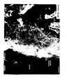
Figure 1 shows enriched nickel regions at the oxide interface. - One object of the present invention is hydrogen storage alloys that exhibit improved capacity.
- These and other objects of the present invention are satisfied by the following electrochemical hydrogen storage alloys and methods for forming such alloys:
- A disordered electrochemical hydrogen storage alloy comprising:
(Base Alloy)aCobMncFedSne
- An electrochemical hydrogen storage alloy having an enriched Ni alloy surface at the oxide interface.
- A method of forming an electrochemical hydrogen storage alloy having enriched Ni regions at the oxide interface comprising the steps of: formulating an electrochemical hydrogen storage alloy containing components that are preferentially corroded during activation; and activating said alloy to produce said enriched Ni regions.
- A method of forming an electrochemical hydrogen storage alloy having enriched Ni regions at the oxide interface comprising the steps of: formulating a first electrochemical hydrogen storage alloy; formulating a second alloy containing components that are preferentially corroded during activation to leave enriched Ni regions; mechanically alloying said first alloy and said second alloy; and activating said mechanically alloyed first and second alloys.
- An electrochemical hydrogen storage cell comprising: a negative electrode composed of a disordered electrochemical alloy having the following composition:
(Base Alloy)aCobMncFedSne
where said Base Alloy comprises 0.1 to 60 atomic percent Ti, 0.1 to 40 atomic percent Zr, 0 to 60 atomic percent V, 0.1 to 57 atomic percent Ni, and 0 to 56 atomic percent Cr; b is 0 to 7.5 atomic percent: c is 13 to 17 atomic percent; d is 0 to 3.5 atomic percent; e is 0 to 1.5 atomic percent; and a + b + c + d + e = 100 atomic percent. - The disordered metal hydride alloy materials of the present invention are designed to have unusual two and three dimensional electronic configurations by varying the three dimensional interactions of constituent atoms and their various orbitals. Disorder in these alloys comes from compositional, positional, and translational relationships as well as disorder provided by the number, position, and size of crystallites of atoms that are not limited by conventional crystalline symmetry in their freedom to interact. This disorder can be of an atomic nature in the form of compositional or configurational disorder provided throughout the bulk or in numerous regions of the material. These disordered alloys have less order than the highly ordered crystalline structures which provide the single phase materials such as used for many of the electrode alloys of the prior art. The types of disordered structures which provide the local structural chemical environments for improved hydrogen storage characteristics in accordance with the present invention are multicomponent polycrystalline materials lacking long range compositional order; microcrystalline materials; amorphous materials having one or more phases; multiphase materials containing both amorphous and crystalline phases; or mixtures thereof.
- The framework for disordered metal hydride alloys is a host matrix of one or more elements. The host elements are chosen in general to be hydride formers and can be lightweight elements. The host matrix elements can be, for example, based on either LaNi or TiNi. The host matrix elements are modified by incorporating selected modifier elements, which may or may not be hydride formers.
The inventors have found through extensive analysis that regardless of the initial host matrix materials, when numerous modifier elements are introduced (such as those described in the present invention) the result is a disordered material that has superior electrochemical properties. The improvement in electrochemical properties is due to an increase in the number and spectrum of catalytically active, hydrogen storage sites. In particular, multi-orbital modifiers, for example transition elements, provide a greatly increased number of storage sites due to the various bonding configurations available. This results in an increase in energy density. Modification that results in a non-equifibrium material having a high degree of disorder provides unique bonding configurations, orbital overlap and hence a spectrum of bonding sites. Due to the different degrees of orbital overlap and the disordered structure, an insignificant amount of structural rearrangement occurs during charge/discharge cycles, or during rest periods, resulting in long cycle and shelf life. - The hydrogen storage and other electrochemical characteristics of the electrode materials of the present invention can be controllably altered depending on the type and quantity of host matrix material and modifier elements selected for making the negative electrode materials. The negative electrode alloys of the present invention are resistant to degradation by poisoning due to the increased number of selectively designed storage and catalytically active sites which also contribute to long cycle life. Also, some of the sites designed into the material can bond with and resist poisoning without affecting the active hydrogen sites. The materials thus formed have a very low self discharge and hence good shelf life.
- As discussed in
U.S. Patent No. 4,716,088 (the contents of which are specifically incorporated by reference) it is known that the steady state surface composition of V-Ti-Zr-Ni alloys can be characterized as having a relatively high concentration of metallic nickel. An aspect of the present invention is a significant increase in the frequency of occurrence of these nickel regions as well as a more pronounced localization of these regions More specifically, the materials of the present invention have enriched nickel regions of 50-70 Å in diameter distributed throughout the oxide interface and varying in proximity from 2-300 Å, preferably 50-100 Å, from region to region. This is illustrated in theFigure 1 , where the nickel regions 1 are shown as what appear as grains on the surface of the oxide interface 2 at 178,000 X. As a result of the increase in the frequency of occurrence of these nickel regions, the materials of the present invention exhibit significantly increased catalysis and conductivity. The increased density of Ni regions in the present invention provides powder particles having an enriched Ni surface. Prior to the present invention Ni enrichment was attempted unsuccessfully using microencapsulation. The method of Ni encapsulation results in the deposition of a layer of Ni about 100 Å thick at the metal-electrolyte interface. Such an amount is excessive and results in no improvement of performance characteristics. - The enriched Ni regions of the present invention can be produced via two general fabrication strategies:
- 1) Specifically formulate an alloy having a surface region that is preferentially corroded during activation to produce the described enriched Ni regions. Without wishing to be bound by theory, it is believed, for example, that Ni is in association with an element such as Al at specific surface regions and that this element corrodes preferentially during activation, leaving the enriched Ni regions described above. "Activation" as used herein specifically refers to "etching" or other methods of removing excessive oxides, such as described in
U.S. Patent No. 4,716,088 , as applied to electrode alloy powder, the finished electrode, or at any point in between in order to improve the hydrogen transfer rate. - 2) Mechanically alloy a secondary alloy to a hydride battery alloy, where the secondary alloy will preferentially corrode to leave enriched nickel regions. An example of such a secondary alloy is NiAl.
- Alloys having enriched Ni regions can be formulated for every known type of hydride battery alloy system, including, but not limited to, Ovonic, TiVZrNi type, modified LaNi 5 type, mischmetal, and LaNi5 alloys as well as the Mg alloys described in copending
U.S. Patent Application No. 08/259,793 . - More specific examples of hydride alloys that can be specifically formulated or mechanically alloyed with a secondary alloy as described in 1) and 2) above to produce enriched Ni regions are the following: Alloys represented by the formula ZrMnwVxMyNiz1 where M is Fe or Co and w1 x1 y1 and z are mole ratios of the respective elements where 0.4 ≤ w ≤ 0.8.0.1≤x≤0.3.0≤y≤0.2.1.0≤z≤1.5, and 2.0≤ w+x+y+z ≤ 2.4. Alloys corresponding substantially to the formula LaNi5 in which one of the components La or Ni is substituted by a metal M selected from Groups Ia, II, III, IV, and Va of the Periodic Table of the Elements other than lanthanides, in an atomic proportion which is higher than 0.1% and lower than 25%. Alloys having the formula TiV2-xNix, where x = 0.2 to 0.6. Alloys having the formula TiaZrbNicCrdMx, where M is Al, Si, V, Mn, Fe, Co, Cu, Nb, Ag, or Pd, 0.1 ≤ a ≤ 1.4, 0.1 ≤ b ≤ 1.3, 0.25 ≤ c ≤ 1.95, 0.1 ≤ d ≤ 1.4, a + b + c + d = 3, and 0 ≤ x ≤ 0.2. Alloys having the formula ZrModNio where d = 0.1 to 1.2 and e = 1.1 to 2.5. Alloys having the formula Ti1-xZrxMn2-y-zCryVz
where 0.05 ≤ x ≤ 0.4, 0 < y ≤ 1.0, and 0 < z ≤ 0.4. Alloys having the formula LnM5 where Ln is at least one lanthanide metal and M is at least one metal chosen from the group consisting of Ni and Co. Alloys comprising at least one transition metal forming 40-75% by weight of the alloy chosen from Groups II, IV, and V of the Periodic System, and at least one additional metal, making up the balance of the alloy, alloyed with the at least one transitional metal, this additional metal chosen from the group consisting of Ni, Cu, Ag, Fe, and Cr-Ni steel. Alloys comprising a main texture of Mm -Ni system; and a plurality of compound phases where each compound phase is segregated in the main texture, and wherein the volume of each of the compound phases is less than about 10 µm3. - The most preferred alloys having enriched Ni regions are allows having the following composition:
(Base Alloy)aCobMncFadSne
where the Base Alloy comprises 0.1 to 60 atomic percent Ti, 0.1 to 40 atomic percent Zr, 0 to 60 atomic percent V, 0.1 to 57 atomic percent Ni, and 0 to 56 atomic percent Cr; b is 0 to 7.5 atomic percent; c is 13 to 17 atomic percent; d is 0 to 3.5 atomic percent; e is 0 to 1.5 atomic percent; and a + b + c + d + e = 100 atomic percent. - The production of the Ni regions of the present invention are consistent with a relatively high rate of removal through precipitation of the oxides of titanium and zirconium from the surface and a much lower rate of nickel solubilization, providing a degree of porosity to the surface. The resultant surface has a higher concentration of nickel than would be expected from the bulk composition of the negative hydrogen storage electrode. Nickel in the metallic 17 state is electrically conductive and catalytic, imparting these properties to the surface. As a result, the surface of the negative hydrogen storage electrode is more catalytic and conductive than if the surface contained a higher concentration of insulating oxides.
- One important consideration in formulating the alloys of the present invention involves formulating specific alloys that have the proper balance of corrosion and passivation characteristics to form exceptional electrochemical alloys. According to the present invention, this process involves choosing modifiers from those set forth in Table 1, below.
Table 1 I II III IV Ca V B Cu Be Ti Bi Th Y Zr In Si Cr Sb Zn Al Li Fe La Sn F - In general, when added as modifiers the elements described in Table 1 make the following contributions to the final alloy mixture:
- i) in group I, the elements alter corrosion as well as storage and bonding characteristics;
- ii) in group II, V, Ti, and Zr alter bond strength and corrosion, and Cr, Al, Fe, and Sn alter corrosion, passivation, and catalysis;
- iii) in group III, all the elements are glass formers and affect the formation of crystalline lattices; and
- iv) in group IV. Cu, Th, Si, Zn, Li, La, and F affect disorder and alter density of state.
- As used herein, the term "Base Alloy" refers to a disordered alloy having a base alloy (as this term is described in
U.S. Patent No. 4,551,400 ) that is a disordered multicomponent alloy having at least one structure selected from the group consisting of amorphous, microcrystalline, polycrystalline, and any combination of these structures. The terms "amorphous," "microcrystalline," and "polycrystalline" are used as defined inU.S. Patent No. 4,623,597 , the contents of which are incorporated by reference. The alloys of the present invention are not limited to any particular structure. Preferably, the materials of the present invention are classified as having a disordered structure and encompass materials that have commonly been referred to by a variety of other terms such as AB,TiVZrNi type, modified LaNi 5' LaNi5, mischmetal, C14' C15' Laves phase, etc. - More specific examples of Base Alloys are the following: An alloy represented by the formula ZrMnwVxMyNiz, where M is Fe or Co and w, x, y, and z are mole ratios of the respective elements where 0.4 ≤ w ≤0.8. 0.1≤ x ≤ 0.3. 0 ≤ y ≤ 0.2, 1.0 ≤ z ≤ 1.5. and 2.0≤ w+x+y+z ≤ 2.4. An alloy corresponding substantially to the formula LaNi5 in which one of the components La or Ni is substituted by a metal M selected from Groups Ia, II, III, IV, and Va of the Periodic Table of the Elements other than lanthanides, in an atomic proportion which is higher than 0.1% and lower than 25%. An alloy having the formula TiV2-xNix, where x = 0.2 to 0.6. An alloy having the formula TiaZrbNicCrdMx, where M is Al, Si, V, Mn, Fe, Co, Cu, Nb, Ag, or Pd, 0.1 ≤ a ≤1.4. 0.1 ≤ b ≤ 1.3, 0.25 ≤ c ≤ 1.95,0.1 ≤ d ≤ 1.4. a + b + c + d = 3. and 0 ≤ x ≤ 0.2. An alloy having the formula ZrModNie where d = 0.1 to 1.2 and e = 1.1 to 2.5. An alloy having the formula Ti1-xZrxMn2-y-zCryVz where 0.05 ≤ x ≤ 0.4, 0 < y ≤ 1.0, and 0 < z ≤ 0.4. An alloy having the formula LnM5 where Ln is at least one lanthanide metal and M is at least one metal chosen from the group consisting of Ni and Co. An alloy comprising at least one transition metal forming 40-75% by weight of the alloy chosen from Groups II, IV, and V of the Periodic System, and at least one additional metal, making up the balance of the alloy, alloyed with the at least one transitional metal, this additional metal chosen from the group consisting of Ni, Cu, Ag, Fe, and Cr-Ni steel. An alloy comprising a main texture of Mm -Ni system; and a plurality of compound phases where each compound phase is segregated in the main texture, and wherein the volume of each of the compound phases is less than about 10 µm3.
- The preferred formulations of the Base Alloy described in the present invention contain 0.1 to 60 atomic percent Ti, 0.1 to 40 atomic percent Zr, 0 to 60 atomic percent V, 0.1 to 57 atomic percent Ni, and 0 to 56 atomic percent Cr. The most preferred formulations of this Base Alloy contain 0.1 to 60 atomic percent Ti, 0.1 to 40 atomic percent Zr, 0.1 to 60 atomic percent V, 0.1 to 57 atomic percent Ni, and 0 to 56 atomic percent Cr.
- In general, the alloys of the present invention comprise negative electrodes for metal hydride cells that exhibit extremely high storage capacity and other significant quantitative improvements in their performance characteristics compared to prior art cells. Surprisingly, embodiments of the present invention show improvement in most, if not all, of their performance characteristics, and thus can be considered universal application cells.
- In accordance with the present invention, it has been found that preferred alloys of the present invention described above and in the Summary of the Invention can be further classified as having a disordered microstructure where hydrogen in a particular phase is not easily discharged either through low surface area, or through an oxide of limited porosity or catalytic property. Specific examples of the alloys of the present invention are set forth in Table 2, below.
Table 2 1. V5Ti9Zr27Ni38Cr5Mn16 14. V4Ti9Zr27Ni37Co5Mn15Fe3Sn0.4 2. V5Ti9Zr27Ni38Co5Mn16 15. V3Ti9Zr28Ni37Co5Mn15Fe3Sn0.6 3. V5Ti9Zr26Ni38Co5Mn16Fe1 16. Ti10Zr28Ni36Co5Cr5Mn16 4. V5Ti9Zr26Ni38Co5Mn15Fe2 17. Ti10Zr27Ni35Co5Cr4Mn13Fe5 5. V5Ti9Zr26Ni37Co5Mn15Fe3 18. Ti12Zr29Ni34Co5Cr5Mn15, 6. V5Ti9Zr26Ni36Co5Mn15Fe4 19. Ti13Zr30Ni34Co5Cr3Mn15 7. V5Ti9Zr26Ni35Co5Mn15Fe5 20. Ti12Zr29Ni34Co7Cr1Mn15Fe2 8. V7Ti9Zr24Ni38Co5Mn16Fe3 21. V1Ti10Zr28Ni34Cr3Co6Mn14Fe2 9. V6Ti9Zr28Ni35Co5Mn15Fe2 22. V2Ti10Zr26N34Cr3Co6Mn14Fe2Sn1 10. V4Ti10Zr29Ni35Co5Mn15Fe2 23. V0.2T10Zr28Ni36Co5Cr5Mn16 11. V4Ti9Zr28N37Co5Mn15Fe2Sn0.4 24. V0.2Ti12Zr29Ni34CO7Cr1Mn15Fe2 12. V3Ti9Zr26Ni38Co5Mn15Fe2Sn0.4 25. V0.5Ti10Zr26Ni34Co6Cr3Mn14Fe2Sn2 13. V4Ti9Zr27Ni38Co5Mn15Fe2Sn0.4 - The affects of the addition of Mn can be seen in negative electrode materials of the present invention where the Base Alloy is modified by 12 to 17 atomic percent Mn. In addition, the affects of Mn can also be observed when the Base Alloy is modified by one of the following combinations:
- (i) 6.5 to 7.5 atomic percent Co, 13 to 17 atomic percent Mn, and 0.5 to 2.5 atomic percent Fe;
- (ii) 5.5 to 6.5 atomic percent Co, 13.5 to 14.5 atomic percent Mn, 1.5 to 2.5 atomic percent Al, and 0.25 to 1.0 atomic percent Fe;
- (iii) 3.5 to 5.5 atomic percent Co, 14.5 to 15.5 atomic percent Mn, 0.5 to 2.5 Fe, and 0.2 to 1.0 Zn;
- (iv) 3.5 to 5 atomic percent Co, 14.5 to 15.5 atomic percent Mn, 0.5 to 2.5 atomic percent Fe, and 0.2 to 1.0 atomic percent Sn.
- Co has become one of the most widely used elements in rechargeable batteries. Because of its limited supply, Co has also become more costly to use. Recently, the price of Co has increased 5%. It is estimated that the price of Co will increase by as much as 30% by the year 2000. In response to these market forces, the inventors have successfully reduced the amount of Co necessary in alloys of the present invention so that the optimized alloys contain from 0-6 atomic % total Co. In particular, alloy No. 1, as set forth in Table 1, above, has been successfully used in prismatic electric vehicle batteries.
- Though not wishing to be bound by theory, it is believed that in the alloys of the present invention, Mn alters the microstructure in such a way that the precipitation of phases having hydrogen bond strengths is outside of the range of electrochemical usefulness is inhibited. One way in which Mn appears to accomplishes this is by increasing the mutual solubility of the other elements within the primary phases during solidification. In addition, Mn functions at the electrochemically active surface oxide as a catalyst. The multiple oxidation states of Mn are believed to catalyze the electrochemical discharge reaction by increasing the porosity, conductivity, and surface area of the active surface oxide film. This results in a significant increase in storage capacity. (See, Table 4.)
- In addition to increasing capacity, Mn has other effects such as enhanced low temperature performance, low cell pressure, and high cycle life. These effects are discussed in detail in U.S Patent
No. 5,277,999 , the contents of which are incorporated by reference. - Mn can also act as a replacement for Fe. Though not wishing to be bound by theory, it is believed that when Mn is present without Fe, Mn assists the electrochemical discharge reaction at low temperature by promoting bulk diffusion of hydrogen at low temperature and also by catalyzing the reaction of hydrogen and hydroxyl ions at the alloy surface. Because of the low temperature properties of such alloys, it appears that Mn's catalytic properties are emphasized when Fe is not present, or at least present in only low concentrations.
- Mn can also be substituted for Co. Though not wishing to be bound by theory, it is believed that in the alloys described above, Mn alters the microstructure and acts as a catalyst at the electrochemically active surface oxide.
- The beneficial effects of Mn and Fe have also been detailed in
U.S. Patent No. 5,096,667 ,U.S. Patent No. 5,104,617 , andU.S. Patent No. 5,238,756 . The contents of all of these references are incorporated by reference. - It is noted in
U.S. Patent 5,104,617 that it was widely believed that the inclusion of Fe in metal hydride hydrogen storage alloy materials would deleteriously effect electrochemical performance. This belief was due to the knowledge that Fe readily oxidizes and corrodes, particularly in the presence of an alkaline electrolyte. Oxidation reduces the performance of a metal hydride electrode in many ways, and oxides of Fe were known in the prior art to adversely affect the nickel hydroxide positive electrode, particularly with respect to charging efficiency and thus capacity and cycle life. - Many of the alloys of the present invention involve Mn. The effects of the addition of Mn to these alloys is generally discussed in
U.S. Patent No. 5,096,667 . The addition of Mn usually results in improved charging efficiency. Though not wishing to be bound by theory, this effect appears to result from Mn's ability to improve the charging efficiency of alloys it is added to by improving oxidation resistance and oxygen recombination. It has been observed that oxygen gas generated at the nickel hydroxide positive electrode recombined at the surface of the metal hydride electrode. Oxygen recombination is an especially aggressive oxidizer of its environment, even compared to the alkaline electrolyte. - It is possible that the modifier elements of the Base Alloy of the present invention, particularly Mn and Fe, and most particularly Co, either alone, or in combination with Mn and/or Al for example, act to catalyze oxygen reduction, thereby avoiding or reducing the oxidation of the surrounding elements in the metal hydride alloy. It is believed that this function of the modified alloys reduces or even eliminates the formation and build up of detrimental surface oxide, thereby providing a thinner and more stable surface. While not wishing to be bound by theory, it is believed that several additional factors may explain the unexpected behavior of Mn and Fe in the Base Alloys of the present invention:
- (1) The combination of Mn and excess Fe may affect the bulk alloy by inhibiting the bulk diffusion rate of hydrogen within the metal through the formation of complex phase structures, either by effecting the grain boundaries or by affecting the equilibrium bond strength of hydrogen within the metal. In other words, the temperature dependance of the hydrogen bond strength may be increased thereby decreasing the available voltage and capacity available under low temperature discharge.
- (2) It is believed that the combination of Mn and excess Fe may result in a lower electrode surface area for metallurgical reasons by increasing the ductility of the alloy and thereby reducing the amount of surface area formation during the activation process.
- (3) It is believed that the combination of Mn and excess Fe to these alloys may inhibit low temperature discharge through the alteration of the oxide layer itself with respect to conductivity, porosity, thickness, and/or catalytic activity. The oxide layer is an important factor in the discharge reaction and promotes the reaction of hydrogen from the Base Alloy of the present invention and hydroxyl ion from the electrolyte. We believe this reaction is promoted by a thin, conductive, porous oxide having some catalytic activity.
- The combination of Mn and excess Fe does not appear to be a problem under room temperature discharge, but has shown a surprising tendency to retard the low temperature reaction. The formation of a complex oxide could result in a subtle change in oxide structure such as pore size distribution or porosity. Since the discharge reaction produces water at the metal hydride surface and within the oxide itself, a small pore size may be causing a slow diffusion of K+ and OH ions from the bulk of the electrolyte to the oxide. Under room temperature discharge where polarization is almost entirely ohmic to low temperature discharge where activation and concentration polarization components dominate the physical structure of the oxides with Fe and Mn compared to Mn alone could be substantially different.
- Still another possible explanation is that the Mn and Fe have multivalent oxidation states. It is considered that some elements within the oxide may in fact change oxidation state during normal state of charge variance as a function of the rate of discharge and can be both temperature, fabrication, can compositionally dependant. It is possible these multiple oxidation states have different catalytic activity as well as different densities that together effect oxide porosity.
- A possible problem with a complex oxide containing both Mn and excess Fe could be that the Fe component retards the ability of the Mn to change oxidation state if present in large quantities.
- The function of Sn addition to the alloy is twofold. First, a small addition of Sn assists activation of the alloy as used in electrodes of the NiMh battery. Though not wishing to be bound by theory, this may be due to desirable corrosion during the initial heat treatment. Sn addition also has the desirable function of cost reduction, as Sn containing alloy allows the use of lower cost versions of Zirconium metal such as Zircalloy.
- Throughout the preceding discussion with respect to the oxide it should be noted that the oxide also contains other components of the Base Alloy of the present invention, such as V, Ti, Zr, Ni, and /or Cr and other modifier elements. The discussion of a complex oxide of Mn and Fe is merely for the sake of brevity and one skilled in the art should not infer that the actual mechanism cannot also include a different or more complex explanation involving other such elements.
- Negative electrodes using alloys of the present invention can be used in many types of hydrogen storage cells and batteries. These include flat cells having a substantially flat plate negative electrode, a separator, and a positive electrode or counter electrode that is substantially flat and aligned to be in operative contact with the negative electrode; jelly-roll cells made by spirally winding a flat cell about an axis; and prismatic cells for use in electric vehicles, for example. The metal hydride cells of the present invention can use any appropriate kind of container, and can be constructed, for example of metal or plastic.
- A 30 weight percent aqueous solution of potassium hydroxide is a preferred electrolyte.
- In a particularly preferred embodiment, alloys used in conjunction with advanced separator materials as disclosed in
U.S. Patent No. 5,330,861 yield improved performance over prior art alloys for certain electrochemical applications. - Besides the improved technical performance discussed above, alloy modification offers cost advantages of up to 30%. One of the dominant factors effecting base alloy cost is the cost of vanadium metal. In
U.S. Patent No. 5,002,730 incorporated by reference, vanadium in the form of V-Ni or V-Fe offers significant cost advantages over pure vanadium. Such cost improvements can be increased in the Base Alloys of the present invention through the use of V-Fe. - Alloy materials described in Table 2, above, and comparison materials described in Table 3 were prepared and fabricated as described below into negative electrode materials. The specific alloys used are referred to in the Tables of each specific Example. The numbering of the alloys is consistent throughout the application and refers to Table 2 or Table 3.
TABLE 3
COMPARISON MATERIALSC1. V22Ti18Zr16Ni32Cr7Co7 C2. V20.8Ti15Zr15Ni30Cr6.6Co6.6Mn3.6Al2.7 C3. V22Ti16Zr16Ni39Fe7 C4. V22Ti16Zr16Ni34Co7Fe8 C5. V21Ti15Zr15Ni31Cr6Co6Fe8 C6. V15Ti15Zr21Ni31Cr6Co6Fe8 C7. V18Ti15Zr18Ni31Cr6Co6Fe4 C8. V22Ti11Zr21Ni39Fe7 C9. V18Ti15Zr18Ni29Cr5Co7Mn8 - The alloys of Tables 2 and 3 were prepared by weighing and mixing starting materials of the component elements into a graphite crucible as described in
U.S. Patent No. 5,002,730 to Fetcenko and4,948,423 to Fetcenko, et al . The crucible and its contents were placed in a vacuum furnace which was evacuated and then pressurized with approximately one atmosphere of argon. The crucible contents were melted by high frequency induction heating while under the argon atmosphere. The melting was carried out at a temperature of about 1500°C until a uniform melt was obtained. At that time, the heating was terminated and the melt was allowed to solidify under an inert atmosphere blanket. - The ingot of alloy material was then reduced in size in a multi-step process. The first step involved a hydriding/dehydriding process substantially as described in
U.S. Patent No. 4,983,756 to Fetcenko, et al. , entitled Hydride Reactor Apparatus for Hydrogen Comminution of Metal Hydride Hydrogen Storage Alloy Material, the disclosure of which is specifically incorporated by reference. In this first step, the alloy was reduced in size to less than 100 mesh. Subsequently, the material obtained from the hydriding/dehydriding process was further reduced in size by an impact milling process in which the particles were tangentially and radially accelerated against an impact block. This process is described inU.S. Patent No. 4,915,898 , entitled Method for the Continuous Fabrication of Comminuted Hydrogen Storage Alloy Negative Electrode Material, the disclosure of which is specifically incorporated by reference. - A fraction of the alloy material having a particle size of less than 200 mesh and a mass average particle size of about 400 mesh (38 microns) was recovered from the impact milling process and bonded to a nickel screen current collector by a process which involves disposing a layer of alloy material onto the current collector and compacting the powder and collector. Compacting was carried out under an inert atmosphere with two separate compaction steps, each at a pressure of about 16 tons per square inch. After compaction, the current collector and the powder adhered to it were sintered in an atmosphere of about 2 atomic percent hydrogen with the balance argon to form negative electrode materials. (In general, sintering may not be required in all applications. The necessity of sintering depends, of course, on the overall cell design and factors such as the state of charge balancing.
- These alloys and negative electrodes were activated using the alkaline etch treatment described in
U.S. Patent No. 4,716,088 , the disclosure of which is specifically incorporated by reference. As a practical matter some oxidation occurs during electrode fabrication, and thus, exposing the alloy powder or negative electrodes of the present invention to an alkaline solution to "etch" or alter the nature of the surface oxides that form yields a variety of beneficial results. For example, it is believed that etching alters the surface condition of the alloy powder or formed negative electrode material in such a way that improved charging efficiency is achieved on even the first charge cycle; promotes the ionic diffusion required for the electrochemical discharge process; creates an oxidation state gradient at the surface of the material; and alters the surface oxide to yield greater charge acceptance. As mentioned by Ogawa in Proceedings of the 1988 Power Sources Symposium, Chapter 26, Metal Hydride Electrode for High Energy Density Sealed Nickel-Metal Hydride Battery similar affects can be achieved by "etching" the alloy powder and then forming a negative electrode from this etched powder. See also,JPA 05/021 059 JPA 05/013 077 - Prepared negative electrodes were assembled with nickel hydroxide positive electrodes into sealed "C" cells having a resealable vent, as described in
U.S. Patent No. 4,822,377 , using a 30 % KOH electrolyte. - Finished cells prepared as described above using the alloys set forth in Table 3, below, were subjected to charging and discharging conditions and the Energy Density (mAh/g) determined.
- The data obtained from these tests are set forth in Table 4, below.
TABLE 4
ENERGY DENSITYALLOY Energy Density (mAh/g) C1 320 C2 315 C3 300 C4 300 C5 290 C6 315 C7 315 C8 300 1 375 2 361 16 342 17 379 - Corrosion measurements were conducted using electrodes fabricated from the alloys listed in Table 5. These electrodes were prepared by cutting a thin (-1mm thick) slice from an ingot of alloy material. A copper wire for electrical measurements was attached to one face of the slice using silver epoxy cement. The electrode was mounted in epoxy resin so that only the face on which the copper wire was attached was covered; the opposite face of the electrode was exposed. The exposed face was polished using 0.3 micron aluminum oxide paste and its geometric area determined for the corrosion measurements.
- The corrosion potentials (Ecorr) and corrosion currents (icorr) of these electrodes were measured using an EG&G PARC corrosion measurement instrument. The measurements were conducted in 30% KOH solution. The corrosion potential of each electrode was determined by measuring the open circuit potential against a Hg/HgO reference electrode about 20 min after the electrode was dipped in solution. The corrosion currents was measured using the polarization resistance (linear polarization) technique. This technique was performed by applying a controlled-potential scan of 0.1 mV/sec over a ±20 mV range with respect to Ecorr. The resulting current was plotted linearly versus the potential. The slope of this potential current function Ecorr is the Polarization Resistance (Rp). Rp was used together with the Tafel Constant β (assumed as 0.1V/decade) to determine icorr using the formula Rp = βAβc/ (2.3 (icorr)(βA + βc)))
TABLE 5
CORROSION POTENTIALSAlloy Series 1 icorr x 10(uA/cm2) Series 2 icorr x 10(uA/cm2) C9 5 8.7 1 3.3 3.5 16 1.7 1.0 - In view of the above, it is obvious to those skilled in the art that the present invention identifies and encompasses a range of alloy compositions which, when incorporated as a negative electrode in metal hydride cells results in batteries having improved performance characteristics.
- The drawings, discussion, descriptions, and examples of this specification are merely illustrative of particular embodiments of the invention and are not meant as limitations upon its practice. It is the following claims, including all equivalents, that define the scope of the invention.
Claims (1)
- An electrochemical hydrogen storage alloy in contact with electrolyte comprising:hydrogen storage elements and modifier elements, the modifier elements including; Co, Mn and Al; andan oxide interface between the electrolyte and the bulk alloy, said oxide interface including enriched nickel regions distributed throughout.
Applications Claiming Priority (3)
| Application Number | Priority Date | Filing Date | Title |
|---|---|---|---|
| US08/423,072 US5536591A (en) | 1990-04-26 | 1995-04-17 | Electrochemical hydrogen storage alloys for nickel metal hydride batteries |
| EP96910746A EP0823134B1 (en) | 1995-04-17 | 1996-04-04 | Improved electrochemical hydrogen storage alloys for nickel metal hydride batteries |
| EP03013472A EP1365462B2 (en) | 1995-04-17 | 1996-04-04 | Improved electrochemical hydrogen storage alloys for nickel metal hydride batteries |
Related Parent Applications (3)
| Application Number | Title | Priority Date | Filing Date |
|---|---|---|---|
| EP03013472A Division EP1365462B2 (en) | 1995-04-17 | 1996-04-04 | Improved electrochemical hydrogen storage alloys for nickel metal hydride batteries |
| EP96910746.5 Division | 1996-10-24 | ||
| EP03013472.0 Division | 2003-06-25 |
Publications (2)
| Publication Number | Publication Date |
|---|---|
| EP1997773A2 true EP1997773A2 (en) | 2008-12-03 |
| EP1997773A3 EP1997773A3 (en) | 2011-12-21 |
Family
ID=23677583
Family Applications (3)
| Application Number | Title | Priority Date | Filing Date |
|---|---|---|---|
| EP08151625A Withdrawn EP1997773A3 (en) | 1995-04-17 | 1996-04-04 | Improved electrochemical hydrogen storage alloys for nickel metal hydride batteries |
| EP96910746A Revoked EP0823134B1 (en) | 1995-04-17 | 1996-04-04 | Improved electrochemical hydrogen storage alloys for nickel metal hydride batteries |
| EP03013472A Expired - Lifetime EP1365462B2 (en) | 1995-04-17 | 1996-04-04 | Improved electrochemical hydrogen storage alloys for nickel metal hydride batteries |
Family Applications After (2)
| Application Number | Title | Priority Date | Filing Date |
|---|---|---|---|
| EP96910746A Revoked EP0823134B1 (en) | 1995-04-17 | 1996-04-04 | Improved electrochemical hydrogen storage alloys for nickel metal hydride batteries |
| EP03013472A Expired - Lifetime EP1365462B2 (en) | 1995-04-17 | 1996-04-04 | Improved electrochemical hydrogen storage alloys for nickel metal hydride batteries |
Country Status (11)
| Country | Link |
|---|---|
| US (1) | US5536591A (en) |
| EP (3) | EP1997773A3 (en) |
| JP (3) | JP3241047B2 (en) |
| KR (1) | KR100370645B1 (en) |
| AU (1) | AU5385596A (en) |
| BR (1) | BR9608176A (en) |
| CA (1) | CA2215666C (en) |
| DE (2) | DE69637665D1 (en) |
| MX (1) | MX194791B (en) |
| TW (1) | TW301806B (en) |
| WO (1) | WO1996033518A1 (en) |
Families Citing this family (54)
| Publication number | Priority date | Publication date | Assignee | Title |
|---|---|---|---|---|
| ES2169169T3 (en) * | 1995-05-09 | 2002-07-01 | Basf Ag | COBALT CATALYSTS. |
| KR100212180B1 (en) * | 1996-03-15 | 1999-08-02 | 윤덕용 | Activation treatment method of ni/mh secondary battery by hot charging |
| GB9607342D0 (en) * | 1996-04-09 | 1996-06-12 | Univ Mcgill | Composite hydrogen storage materials for rechargeable hydride electrodes |
| US6330925B1 (en) * | 1997-01-31 | 2001-12-18 | Ovonic Battery Company, Inc. | Hybrid electric vehicle incorporating an integrated propulsion system |
| JP2982805B1 (en) | 1998-02-19 | 1999-11-29 | 松下電器産業株式会社 | Hydrogen storage alloy for battery, method for producing the same, and alkaline storage battery using the same |
| US6120936A (en) * | 1998-08-27 | 2000-09-19 | Ovonic Battery Company, Inc. | Method for powder formation of a hydrogen storage alloy |
| US6461766B1 (en) * | 1998-08-27 | 2002-10-08 | Ovonic Battery Company, Inc. | Hydrogen storage powder and process for preparing the same |
| US6150054A (en) * | 1998-09-23 | 2000-11-21 | Ovonic Battery Company, Inc. | Nickel positive electrode material comprising rare earth minerals |
| US6306544B1 (en) * | 1999-02-25 | 2001-10-23 | Wilson Greatbatch Ltd. | Cobalt-based alloys as positive electrode current collectors in nonaqueous electrochemical cells |
| US6270719B1 (en) * | 1999-04-12 | 2001-08-07 | Ovonic Battery Company, Inc. | Modified electrochemical hydrogen storage alloy having increased capacity, rate capability and catalytic activity |
| US6841512B1 (en) * | 1999-04-12 | 2005-01-11 | Ovonic Battery Company, Inc. | Finely divided metal catalyst and method for making same |
| JP3998370B2 (en) * | 1999-06-14 | 2007-10-24 | 松下電器産業株式会社 | Hydrogen storage alloy electrode |
| JP2003514353A (en) * | 1999-11-08 | 2003-04-15 | ネオフォトニクス・コーポレイション | Electrodes containing particles of specific size |
| US6492056B1 (en) * | 2000-03-13 | 2002-12-10 | Energy Conversion Devices, Inc. | Catalytic hydrogen storage composite material and fuel cell employing same |
| US7014953B2 (en) * | 2001-03-01 | 2006-03-21 | Texaco Ovoric Fuel Cell, Llc | Regenerative bipolar fuel cell |
| JP4743997B2 (en) | 2001-05-17 | 2011-08-10 | パナソニック株式会社 | Hydrogen storage alloy electrode |
| JP5142428B2 (en) * | 2001-06-21 | 2013-02-13 | パナソニック株式会社 | Method for producing hydrogen storage alloy electrode for nickel metal hydride storage battery |
| KR100658255B1 (en) * | 2001-09-19 | 2006-12-14 | 카와사키 주코교 카부시키 카이샤 | High performance type three-dimensional cell |
| US7169489B2 (en) | 2002-03-15 | 2007-01-30 | Fuelsell Technologies, Inc. | Hydrogen storage, distribution, and recovery system |
| US7399325B1 (en) | 2002-03-15 | 2008-07-15 | Fuelsell Technologies, Inc. | Method and apparatus for a hydrogen fuel cassette distribution and recovery system |
| US20040016769A1 (en) * | 2002-03-15 | 2004-01-29 | Redmond Scott D. | Hydrogen storage, distribution, and recovery system |
| US7097933B2 (en) | 2003-06-09 | 2006-08-29 | Ovonic Battery Company, Inc. | Catalyst for fuel cell oxygen electrodes |
| US6830725B2 (en) * | 2003-04-01 | 2004-12-14 | Texaco Ovonic Battery Systems, Llc | Hydrogen storage alloys having a high porosity surface layer |
| US7250386B2 (en) * | 2003-07-18 | 2007-07-31 | Energy Conversion Devices, Inc. | Quantum limit catalysts and hydrogen storage materials |
| US7344677B2 (en) * | 2004-04-02 | 2008-03-18 | Ovonic Battery Company, Inc. | Hydrogen storage alloys having improved cycle life and low temperature operating characteristics |
| US7261970B2 (en) * | 2004-04-23 | 2007-08-28 | Ovonic Battery Company Inc. | Nickel metal hydride battery design |
| US20060057019A1 (en) | 2004-09-16 | 2006-03-16 | Kwo Young | Hydrogen storage alloys having reduced PCT hysteresis |
| CN101273483B (en) | 2005-09-26 | 2010-05-19 | 松下电器产业株式会社 | Alloy powder for electrode and method for producing same |
| JP4849854B2 (en) | 2005-09-26 | 2012-01-11 | 三洋電機株式会社 | Hydrogen storage alloy electrode, alkaline storage battery, and production method of alkaline storage battery |
| JP5173320B2 (en) | 2007-08-29 | 2013-04-03 | 三洋電機株式会社 | Hydrogen storage alloy electrode and alkaline storage battery using this hydrogen storage alloy electrode |
| WO2009132036A1 (en) * | 2008-04-21 | 2009-10-29 | Quantumsphere, Inc. | Composition of and method of using nanoscale materials in hydrogen storage applications |
| US9425456B2 (en) | 2012-02-07 | 2016-08-23 | Ovonic Battery Company, Inc. | Rechargeable battery cell with improved high temperature performance |
| US9406934B2 (en) | 2012-02-07 | 2016-08-02 | Basf Corporation | Rechargeable battery cell with improved high temperature performance |
| US9272259B2 (en) | 2012-04-19 | 2016-03-01 | Ovonic Battery Company, Inc. | Metal hydride alloys having improved activation and high rate performance |
| US8877378B2 (en) | 2013-01-07 | 2014-11-04 | Ovonic Battery Company, Inc. | Metal hydride alloy with catalyst particles and channels |
| KR20150103714A (en) * | 2013-01-07 | 2015-09-11 | 오보닉 배터리 컴퍼니, 아이엔씨. | Metal hydride alloy |
| US9350014B2 (en) * | 2013-01-07 | 2016-05-24 | Ovonic Battery Company, Inc. | Nanoscale nickel-based catalytic material |
| US9531005B2 (en) | 2013-06-25 | 2016-12-27 | Ovonic Battery Company, Inc. | Synergistic multiphase hydride alloy |
| US10050319B2 (en) | 2014-05-28 | 2018-08-14 | John M. Guerra | Photoelectrochemical secondary cell and battery |
| US9768445B2 (en) | 2014-07-25 | 2017-09-19 | Ovonic Battery Company, Inc. | Activation of laves phase-related BCC metal hydride alloys for electrochemical applications |
| US9859531B2 (en) | 2015-02-06 | 2018-01-02 | Ovonic Battery Company, Inc. | Alkaline and non-aqueous proton-conducting pouch-cell batteries |
| US10587012B2 (en) | 2015-03-26 | 2020-03-10 | Basf Corporation | Electrolyte compositions comprising ionic liquids and metal hydride batteries comprising same |
| CN108886175B (en) | 2016-03-28 | 2022-08-02 | 巴斯夫公司 | Silicon-based solid electrolyte for rechargeable batteries |
| CN114799164A (en) * | 2017-11-06 | 2022-07-29 | 佳能安内华股份有限公司 | Structure and method for manufacturing same |
| WO2022145031A1 (en) | 2020-12-29 | 2022-07-07 | Kawasaki Motors, Ltd. | Processes of hydrogen annealing of si-surfaces |
| WO2022145026A1 (en) | 2020-12-29 | 2022-07-07 | Kawasaki Motors, Ltd. | Si-containing alloy for the anode of proton-conducting rechargeable batteries |
| WO2022145029A1 (en) | 2020-12-29 | 2022-07-07 | Kawasaki Motors, Ltd. | Group 14 element-containing metal hydride with a superlattice structure for use in hydrogen storage. |
| WO2022145028A1 (en) | 2020-12-29 | 2022-07-07 | Kawasaki Motors, Ltd. | Group 14 element-containing metal hydrides with a superlattice structure for use in proton-conducting rechargeable batteries |
| WO2022145030A1 (en) | 2020-12-29 | 2022-07-07 | Kawasaki Motors, Ltd. | Salt containing electrolytes that promote the formation of proton-conducting rechargeable batteries |
| WO2022145027A1 (en) | 2020-12-29 | 2022-07-07 | Kawasaki Motors, Ltd. | Ionic liquid electrolytes including salt additives for use in proton-conducting rechargeable batteries |
| CN116724412A (en) | 2020-12-29 | 2023-09-08 | 川崎摩托株式会社 | Bulk silicon negative electrode for proton-conducting rechargeable battery |
| WO2022239204A1 (en) | 2021-05-13 | 2022-11-17 | Kawasaki Motors, Ltd. | Bipolar battery with proton and hydroxide ion conducting polymer based separator |
| KR20240023632A (en) | 2021-06-21 | 2024-02-22 | 가와사키 모터스 가부시키가이샤 | Proton conductive rechargeable battery and method |
| WO2023007751A1 (en) | 2021-07-30 | 2023-02-02 | Kawasaki Motors, Ltd. | Si-containing metal hydrides with expanded superlattice structure for use in proton-conducting rechargeable electrochemical cells |
Citations (28)
| Publication number | Priority date | Publication date | Assignee | Title |
|---|---|---|---|---|
| US3874928A (en) | 1973-06-29 | 1975-04-01 | Gen Electric | Hermetically sealed secondary battery with lanthanum nickel anode |
| US4107405A (en) | 1975-05-23 | 1978-08-15 | Agence Nationale De Valorisation De La Recherche (Anvar) | Electrode materials based on lanthanum and nickel, and electrochemical uses of such materials |
| US4107395A (en) | 1977-09-20 | 1978-08-15 | Communication Satellite Corporation | Overchargeable sealed metal oxide/lanthanum nickel hydride battery |
| US4112199A (en) | 1975-12-30 | 1978-09-05 | Communications Satellite Corporation | Lanthanum nickel hydride-hydrogen/metal oxide cell |
| US4125688A (en) | 1976-06-24 | 1978-11-14 | Saft-Societe Des Accumulateurs Fixes Et De Traction | Negative electrodes for electric cells |
| US4214043A (en) | 1978-02-03 | 1980-07-22 | U.S. Philips Corporation | Rechargeable electrochemical cell |
| US4216274A (en) | 1969-01-24 | 1980-08-05 | U.S. Philips Corporation | Battery with hydrogen absorbing material of the formula LnM5 |
| US4487817A (en) | 1983-10-21 | 1984-12-11 | Willems Johannes J G S A | Electrochemical cell comprising stable hydride-forming material |
| US4520039A (en) | 1982-09-23 | 1985-05-28 | Sovonics Solar Systems | Compositionally varied materials and method for synthesizing the materials |
| US4551400A (en) | 1984-04-18 | 1985-11-05 | Energy Conversion Devices, Inc. | Hydrogen storage materials and methods of sizing and preparing the same for electrochemical applications |
| US4605603A (en) | 1983-12-26 | 1986-08-12 | Kabushiki Kaisha Toshiba | Hermetically sealed metallic oxide-hydrogen battery using hydrogen storage alloy |
| US4623597A (en) | 1982-04-28 | 1986-11-18 | Energy Conversion Devices, Inc. | Rechargeable battery and electrode used therein |
| US4696873A (en) | 1985-06-21 | 1987-09-29 | Kabushiki Kaisha Toshiba | Rechargeable electrochemical cell with a negative electrode comprising a hydrogen absorbing alloy including rare earth component |
| US4699856A (en) | 1986-06-26 | 1987-10-13 | U.S. Philips Corporation | Electrochemical cell |
| US4716088A (en) | 1986-12-29 | 1987-12-29 | Energy Conversion Devices, Inc. | Activated rechargeable hydrogen storage electrode and method |
| US4728586A (en) | 1986-12-29 | 1988-03-01 | Energy Conversion Devices, Inc. | Enhanced charge retention electrochemical hydrogen storage alloys and an enhanced charge retention electrochemical cell |
| US4822377A (en) | 1988-02-18 | 1989-04-18 | Energy Conversion Devices, Inc. | Method for sealing an electrochemical cell employing an improved reinforced cover assembly |
| US4915898A (en) | 1988-04-25 | 1990-04-10 | Energy Conversion Devices, Inc. | Method for the continuous fabrication of comminuted hydrogen storage alloy material negative electrodes |
| US4948423A (en) | 1989-07-21 | 1990-08-14 | Energy Conversion Devices, Inc. | Alloy preparation of hydrogen storage materials |
| US4983756A (en) | 1988-02-24 | 1991-01-08 | Nitto Boseki Co., Ltd. | Novel choline derivative and method for detemining serum cholinesterase activity using the same |
| US5002730A (en) | 1989-07-24 | 1991-03-26 | Energy Conversion Devices | Preparation of vanadium rich hydrogen storage alloy materials |
| US5096667A (en) | 1989-11-24 | 1992-03-17 | Energy Conversion Devices, Inc. | Catalytic hydrogen storage electrode materials for use in electrochemical cells and electrochemical cells incorporating the materials |
| US5104617A (en) | 1990-04-26 | 1992-04-14 | Energy Conversion Devices, Inc. | Catalytic hydrogen storage electrode materials for use in electrochemical cells and electrochemical cells incorporating the materials |
| US5238756A (en) | 1990-04-26 | 1993-08-24 | Ovonic Battery Company | Electrode alloy having decreased hydrogen overpressure and/or low self-discharge |
| US5277999A (en) | 1991-08-14 | 1994-01-11 | Ovonic Battery Company, Inc. | Electrochemical hydrogen storage alloys and batteries fabricated these alloys having significantly improved performance characteristics |
| US5330861A (en) | 1992-05-07 | 1994-07-19 | Ovonic Battery Company, Inc. | Metal hydride cells having improved cycle life and charge retention |
| US5407761A (en) | 1991-08-14 | 1995-04-18 | Ovinic Battery Company, Inc. | Electrochemical hydrogen storage alloys and batteries fabricated from these alloys having significantly improved capacity |
| US5506069A (en) | 1993-10-14 | 1996-04-09 | Ovonic Battery Company, Inc. | Electrochemical hydrogen storage alloys and batteries fabricated from Mg containing base alloys |
Family Cites Families (4)
| Publication number | Priority date | Publication date | Assignee | Title |
|---|---|---|---|---|
| US4849205A (en) * | 1987-11-17 | 1989-07-18 | Kuochih Hong | Hydrogen storage hydride electrode materials |
| EP0413029B1 (en) * | 1988-12-29 | 1995-09-20 | Matsushita Electric Industrial Co., Ltd. | Method of producing hydrogen-occlusion alloy and electrode using the alloy |
| JP3265652B2 (en) * | 1992-10-09 | 2002-03-11 | 松下電器産業株式会社 | Manufacturing method of alkaline storage battery and its hydrogen storage alloy |
| EP0696823B1 (en) * | 1994-02-25 | 1998-10-28 | Yuasa Corporation | Hydrogen absorbing electrode and production method thereof |
-
1995
- 1995-04-17 US US08/423,072 patent/US5536591A/en not_active Expired - Lifetime
-
1996
- 1996-04-04 KR KR1019970707315A patent/KR100370645B1/en not_active IP Right Cessation
- 1996-04-04 JP JP53177096A patent/JP3241047B2/en not_active Expired - Lifetime
- 1996-04-04 WO PCT/US1996/004651 patent/WO1996033518A1/en active IP Right Grant
- 1996-04-04 BR BR9608176A patent/BR9608176A/en not_active IP Right Cessation
- 1996-04-04 EP EP08151625A patent/EP1997773A3/en not_active Withdrawn
- 1996-04-04 DE DE69637665T patent/DE69637665D1/en not_active Expired - Lifetime
- 1996-04-04 EP EP96910746A patent/EP0823134B1/en not_active Revoked
- 1996-04-04 CA CA002215666A patent/CA2215666C/en not_active Expired - Lifetime
- 1996-04-04 AU AU53855/96A patent/AU5385596A/en not_active Abandoned
- 1996-04-04 EP EP03013472A patent/EP1365462B2/en not_active Expired - Lifetime
- 1996-04-04 DE DE69633665T patent/DE69633665T2/en not_active Expired - Lifetime
- 1996-04-16 TW TW085104502A patent/TW301806B/zh not_active IP Right Cessation
-
1997
- 1997-10-16 MX MX9707964A patent/MX194791B/en unknown
-
1999
- 1999-11-19 JP JP11330602A patent/JP2000144288A/en active Pending
-
2001
- 2001-07-23 JP JP2001221951A patent/JP2002088436A/en active Pending
Patent Citations (28)
| Publication number | Priority date | Publication date | Assignee | Title |
|---|---|---|---|---|
| US4216274A (en) | 1969-01-24 | 1980-08-05 | U.S. Philips Corporation | Battery with hydrogen absorbing material of the formula LnM5 |
| US3874928A (en) | 1973-06-29 | 1975-04-01 | Gen Electric | Hermetically sealed secondary battery with lanthanum nickel anode |
| US4107405A (en) | 1975-05-23 | 1978-08-15 | Agence Nationale De Valorisation De La Recherche (Anvar) | Electrode materials based on lanthanum and nickel, and electrochemical uses of such materials |
| US4112199A (en) | 1975-12-30 | 1978-09-05 | Communications Satellite Corporation | Lanthanum nickel hydride-hydrogen/metal oxide cell |
| US4125688A (en) | 1976-06-24 | 1978-11-14 | Saft-Societe Des Accumulateurs Fixes Et De Traction | Negative electrodes for electric cells |
| US4107395A (en) | 1977-09-20 | 1978-08-15 | Communication Satellite Corporation | Overchargeable sealed metal oxide/lanthanum nickel hydride battery |
| US4214043A (en) | 1978-02-03 | 1980-07-22 | U.S. Philips Corporation | Rechargeable electrochemical cell |
| US4623597A (en) | 1982-04-28 | 1986-11-18 | Energy Conversion Devices, Inc. | Rechargeable battery and electrode used therein |
| US4520039A (en) | 1982-09-23 | 1985-05-28 | Sovonics Solar Systems | Compositionally varied materials and method for synthesizing the materials |
| US4487817A (en) | 1983-10-21 | 1984-12-11 | Willems Johannes J G S A | Electrochemical cell comprising stable hydride-forming material |
| US4605603A (en) | 1983-12-26 | 1986-08-12 | Kabushiki Kaisha Toshiba | Hermetically sealed metallic oxide-hydrogen battery using hydrogen storage alloy |
| US4551400A (en) | 1984-04-18 | 1985-11-05 | Energy Conversion Devices, Inc. | Hydrogen storage materials and methods of sizing and preparing the same for electrochemical applications |
| US4696873A (en) | 1985-06-21 | 1987-09-29 | Kabushiki Kaisha Toshiba | Rechargeable electrochemical cell with a negative electrode comprising a hydrogen absorbing alloy including rare earth component |
| US4699856A (en) | 1986-06-26 | 1987-10-13 | U.S. Philips Corporation | Electrochemical cell |
| US4716088A (en) | 1986-12-29 | 1987-12-29 | Energy Conversion Devices, Inc. | Activated rechargeable hydrogen storage electrode and method |
| US4728586A (en) | 1986-12-29 | 1988-03-01 | Energy Conversion Devices, Inc. | Enhanced charge retention electrochemical hydrogen storage alloys and an enhanced charge retention electrochemical cell |
| US4822377A (en) | 1988-02-18 | 1989-04-18 | Energy Conversion Devices, Inc. | Method for sealing an electrochemical cell employing an improved reinforced cover assembly |
| US4983756A (en) | 1988-02-24 | 1991-01-08 | Nitto Boseki Co., Ltd. | Novel choline derivative and method for detemining serum cholinesterase activity using the same |
| US4915898A (en) | 1988-04-25 | 1990-04-10 | Energy Conversion Devices, Inc. | Method for the continuous fabrication of comminuted hydrogen storage alloy material negative electrodes |
| US4948423A (en) | 1989-07-21 | 1990-08-14 | Energy Conversion Devices, Inc. | Alloy preparation of hydrogen storage materials |
| US5002730A (en) | 1989-07-24 | 1991-03-26 | Energy Conversion Devices | Preparation of vanadium rich hydrogen storage alloy materials |
| US5096667A (en) | 1989-11-24 | 1992-03-17 | Energy Conversion Devices, Inc. | Catalytic hydrogen storage electrode materials for use in electrochemical cells and electrochemical cells incorporating the materials |
| US5104617A (en) | 1990-04-26 | 1992-04-14 | Energy Conversion Devices, Inc. | Catalytic hydrogen storage electrode materials for use in electrochemical cells and electrochemical cells incorporating the materials |
| US5238756A (en) | 1990-04-26 | 1993-08-24 | Ovonic Battery Company | Electrode alloy having decreased hydrogen overpressure and/or low self-discharge |
| US5277999A (en) | 1991-08-14 | 1994-01-11 | Ovonic Battery Company, Inc. | Electrochemical hydrogen storage alloys and batteries fabricated these alloys having significantly improved performance characteristics |
| US5407761A (en) | 1991-08-14 | 1995-04-18 | Ovinic Battery Company, Inc. | Electrochemical hydrogen storage alloys and batteries fabricated from these alloys having significantly improved capacity |
| US5330861A (en) | 1992-05-07 | 1994-07-19 | Ovonic Battery Company, Inc. | Metal hydride cells having improved cycle life and charge retention |
| US5506069A (en) | 1993-10-14 | 1996-04-09 | Ovonic Battery Company, Inc. | Electrochemical hydrogen storage alloys and batteries fabricated from Mg containing base alloys |
Non-Patent Citations (4)
| Title |
|---|
| "Principles and Applications of Amorphicity, Structural Change, and Optical Information Encoding", JOURNAL DE PHYSIQUE, vol. 42, October 1981 (1981-10-01) |
| "The Chemical Basis of Amorphicity: Structure and Function", REV. ROUM. PHYS, vol. 26, no. 8-9, 1981, pages 893 - 903 |
| OGAWA: "Power Sources Symposium", 1988 |
| S. R. OVSHINSKY, THE SHAPE OF DISORDER, 1979 |
Also Published As
| Publication number | Publication date |
|---|---|
| CA2215666A1 (en) | 1996-10-24 |
| DE69633665T2 (en) | 2005-11-03 |
| DE69637665D1 (en) | 2008-10-09 |
| JP2002088436A (en) | 2002-03-27 |
| JP2000144288A (en) | 2000-05-26 |
| KR100370645B1 (en) | 2003-04-10 |
| DE69633665D1 (en) | 2004-11-25 |
| EP0823134B1 (en) | 2004-10-20 |
| MX194791B (en) | 2000-01-06 |
| CA2215666C (en) | 2003-12-30 |
| AU5385596A (en) | 1996-11-07 |
| EP1365462B2 (en) | 2011-07-06 |
| EP0823134A4 (en) | 1998-08-12 |
| JP3241047B2 (en) | 2001-12-25 |
| US5536591A (en) | 1996-07-16 |
| EP1997773A3 (en) | 2011-12-21 |
| MX9707964A (en) | 1998-08-30 |
| KR19990007792A (en) | 1999-01-25 |
| EP1365462A3 (en) | 2008-04-23 |
| EP0823134A1 (en) | 1998-02-11 |
| WO1996033518A1 (en) | 1996-10-24 |
| TW301806B (en) | 1997-04-01 |
| EP1365462A2 (en) | 2003-11-26 |
| EP1365462B1 (en) | 2008-08-27 |
| BR9608176A (en) | 1999-02-09 |
| JPH11503872A (en) | 1999-03-30 |
Similar Documents
| Publication | Publication Date | Title |
|---|---|---|
| EP1365462B1 (en) | Improved electrochemical hydrogen storage alloys for nickel metal hydride batteries | |
| EP0746878B1 (en) | Electrochemical hydrogen storage alloys and batteries fabricated from these alloys | |
| MXPA97007964A (en) | Improved electrochemical hydrogen storage alloys for nickel metal hydride batteries | |
| RU2168244C2 (en) | Electrochemical hydrogen-absorbing alloys and storage cells using heterogeneous powdered particles | |
| EP0765531B1 (en) | ELECTROCHEMICAL HYDROGEN STORAGE ALLOYS AND BATTERIES FABRICATED FROM Mg CONTAINING BASE ALLOYS | |
| US5407761A (en) | Electrochemical hydrogen storage alloys and batteries fabricated from these alloys having significantly improved capacity | |
| RU2162258C2 (en) | Electrochemical hydrogen-absorbing alloys and accumulators made of magnesium base alloys | |
| AU694033C (en) | Electrochemical hydrogen storage alloys and batteries containing heterogeneous powder particles | |
| Ovshinsky et al. | Electrochemical hydrogen storage alloys and batteries fabricated from Mg containing base alloys |
Legal Events
| Date | Code | Title | Description |
|---|---|---|---|
| PUAI | Public reference made under article 153(3) epc to a published international application that has entered the european phase |
Free format text: ORIGINAL CODE: 0009012 |
|
| AC | Divisional application: reference to earlier application |
Ref document number: 0823134 Country of ref document: EP Kind code of ref document: P Ref document number: 1365462 Country of ref document: EP Kind code of ref document: P |
|
| AK | Designated contracting states |
Kind code of ref document: A2 Designated state(s): DE FR GB |
|
| PUAL | Search report despatched |
Free format text: ORIGINAL CODE: 0009013 |
|
| AK | Designated contracting states |
Kind code of ref document: A3 Designated state(s): DE FR GB |
|
| RIC1 | Information provided on ipc code assigned before grant |
Ipc: C01B 3/00 20060101AFI20111115BHEP Ipc: H01M 4/38 20060101ALI20111115BHEP |
|
| AKY | No designation fees paid | ||
| REG | Reference to a national code |
Ref country code: DE Ref legal event code: R108 |
|
| REG | Reference to a national code |
Ref country code: DE Ref legal event code: R108 Effective date: 20120829 |
|
| STAA | Information on the status of an ep patent application or granted ep patent |
Free format text: STATUS: THE APPLICATION IS DEEMED TO BE WITHDRAWN |
|
| 18D | Application deemed to be withdrawn |
Effective date: 20120622 |