EP1998552A2 - Imaging apparatus and image processing program - Google Patents
Imaging apparatus and image processing program Download PDFInfo
- Publication number
- EP1998552A2 EP1998552A2 EP08251879A EP08251879A EP1998552A2 EP 1998552 A2 EP1998552 A2 EP 1998552A2 EP 08251879 A EP08251879 A EP 08251879A EP 08251879 A EP08251879 A EP 08251879A EP 1998552 A2 EP1998552 A2 EP 1998552A2
- Authority
- EP
- European Patent Office
- Prior art keywords
- gradation
- input
- output characteristic
- image data
- dark area
- Prior art date
- Legal status (The legal status is an assumption and is not a legal conclusion. Google has not performed a legal analysis and makes no representation as to the accuracy of the status listed.)
- Granted
Links
Images


Classifications
-
- H—ELECTRICITY
- H04—ELECTRIC COMMUNICATION TECHNIQUE
- H04N—PICTORIAL COMMUNICATION, e.g. TELEVISION
- H04N5/00—Details of television systems
- H04N5/14—Picture signal circuitry for video frequency region
- H04N5/20—Circuitry for controlling amplitude response
- H04N5/202—Gamma control
-
- H—ELECTRICITY
- H04—ELECTRIC COMMUNICATION TECHNIQUE
- H04N—PICTORIAL COMMUNICATION, e.g. TELEVISION
- H04N23/00—Cameras or camera modules comprising electronic image sensors; Control thereof
- H04N23/70—Circuitry for compensating brightness variation in the scene
- H04N23/76—Circuitry for compensating brightness variation in the scene by influencing the image signals
-
- H—ELECTRICITY
- H04—ELECTRIC COMMUNICATION TECHNIQUE
- H04N—PICTORIAL COMMUNICATION, e.g. TELEVISION
- H04N2101/00—Still video cameras
Definitions
- the present invention relates to an imaging apparatus and an image processing program.
- a proposition of an imaging apparatus and an image processing program of the present invention is to maintain lightness of a whole image, while improving contrast of a highlight area, at the time of correcting dark area gradation.
- the imaging apparatus of the present invention includes an image pickup unit picking up a subject image and generating image data, a selecting unit selecting any one of a first photographic mode that does not correct dark area gradation of the image data and a second photographic mode that corrects the dark area gradation of the image data, a gradation conversion processing unit performing a gradation conversion processing according to a first input-output characteristic when the first photographic mode is selected, and performing a gradation conversion processing according to a second input-output characteristic different from the first input-output characteristic when the second photographic mode is selected, and a correcting unit performing a correction of improving lightness of the dark area gradation of the image data subjected to the gradation conversion processing according to the second input-output characteristic by the gradation conversion processing unit when the second photographic mode is selected.
- the second input-output characteristic may have a characteristic realizing an output level which is lower than the output level of the first input-output characteristic, with respect to the same input level.
- the second input-output characteristic may be defined by a gradation curve having a gradient smaller than that of the first input-output characteristic.
- the second input-output characteristic may have a characteristic emphasizing contrast more than the first input-output characteristic.
- the second input-output characteristic may be defined by a gradation curve having a gradient larger than that of the first input-output characteristic.
- the imaging apparatus may further include an obtaining unit obtaining a lightness improvement amount of the dark area gradation by the correcting unit, wherein the gradation conversion processing unit selects any characteristic from among a plurality of predetermined input-output characteristics as the second input-output characteristic according to the lightness improvement amount, and performs the gradation conversion processing according to the selected input-output characteristic, and the correcting unit corrects the dark area gradation of the image data according to the lightness improvement amount.
- the imaging apparatus may further include an obtaining unit obtaining a lightness improvement amount of dark area gradation by the correcting unit, wherein the gradation conversion processing unit determines the second input-output characteristic according to the lightness improvement amount, and performs the gradation conversion processing according to the determined input-output characteristic, and the correcting unit corrects the dark area gradation of the image data according to the lightness improvement amount.
- an image processing program for causing a computer to realize an image processing with respect to the image data to be processed in which the configuration regarding the above invention is expressed by converting the configuration into the program, is also effective as a specific embodiment of the present invention.
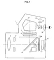
- Fig. 1 is a figure showing a configuration of an electronic camera 1 of the present embodiment.
- the electronic camera 1 includes the following parts a photographic lens 2, an aperture diaphragm 3, a quick return mirror 4, a sub mirror 5, a diffusion screen 6, a condenser lens 7, a pentaprism 8, a beam splitter 9, an ocular lens 10, an imaging lens 11, an AE sensor 12, a shutter 13, an image-capturing sensor 14, and a focus detecting part 15.
- the AE sensor 12 is, for example, a 5-way split photometric sensor.
- the image-capturing sensor 14 is a semiconductor device, such as a CCD (Charge Coupled Device), or a CMOS (Complementary Metal Oxide Semiconductor).
- the focus detecting part 15 performs focus detection in a scheme of, for example, phase difference to detect the focused state of the photographic lens 2.
- the electronic camera 1 performs focus detection in a contrast scheme based on the brightness detected by the AE sensor 12, to detect the focused state of the photographic lens 2. It is preferable that whether the focus detection in a phase difference scheme or the focus detection in a contrast scheme should be performed can be set depending on operation of a user.
- a configuration in which the focused state of the photographic lens 2 is detected by the combination of the focus detection in a phase difference scheme or the focus detection in a contrast scheme, may also be used.
- the electronic camera 1 further includes a monitor 16 such as a liquid crystal display monitor displaying an image etc. generated by way of image pick-up, and a controlling part 1 7 that controls each of the parts.
- the controlling part 1 7 includes a not-shown memory inside thereof, and preliminarily records programs for controlling each of the parts.
- the quick return mirror 4 is arranged at an angle of 45°.
- Light flux which passed through the photographic lens 2 and the aperture diaphragm 3, is then reflected by the quick return mirror 4 to be led to the ocular lens 10 through the diffusion screen 6, the condenser lens 7, the pentaprism 8, and the beam splitter 9.
- a user confirms a construct by viewing the subject image through the ocular lens 10.
- light flux which is divided upward by the beam splitter 9, is re-imaged on the image pick-up plane of the AE sensor 12 through the imaging lens 11.
- light flux which passed through the quick return mirror 4 is led to the focus detecting part 15 through the sub mirror 5.
- the quick return mirror 4 is evacuated to a position shown by a dashed line to open the shutter 13, and the light flux from the photographic lens 2 is led to the image-capturing sensor 14.
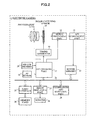
- Fig. 2 is a functional block diagram of the electronic camera 1 of the present embodiment.
- the electronic camera 1 includes the following parts: a timing generator 20, a signal processing part 21, an A/D converting part 22, a buffer memory 23, a bus 24, a card interface 25, a compression and extension part 26, and an image displaying part 27.
- the timing generator 20 supplies an output pulse to the image-capturing sensor 14.
- the image data generated by the image-capturing sensor 14 is temporarily stored on the buffer memory 23 through the signal processing part 21 (an adjusting part of gain corresponding to image pick-up sensitivity is included), and the A/D converting part 22.
- the buffer memory 23 is coupled to the bus 24.
- the card interface 25, the controlling part 17 described in Fig. 1 , the compression and extension part 26, and the image displaying part 27 are coupled to the bus 24.
- the card interface 25 is coupled to a detachable memory card 28 and records image data on the memory card 28.
- switch members 29 (not-shown release buttons and the like are included) of the electronic camera 1, the timing generator 20, and the AE sensor 12 are coupled to the controlling part 17.
- the image displaying part 27 displays an image or the like on the monitor 16 disposed on the back surface of the electronic camera 1.
- the electronic camera 1 includes a gradation non-compression mode in which the dark area gradation of image data is not corrected and a gradation compression mode in which the dark area gradation of image data is corrected. In which mode shooting is performed, is selected in advance by a user through the switch members 29. Moreover, in the gradation compression mode, the magnitude of gradation compression amount (lightness improvement amount) can be set into two stages (large/small). The setting is also performed in advance by the user through the switch members 29.
- Step S1 the controlling part 17 determines whether or not start of shooting is indicated by the user through the switch members 29. Then, if the controlling part 17 determines that the start of shooting is indicated, the controlling part 1 7 will proceed to Step S2.
- the controlling part 17 controls each of the parts, and picks up a subject image by the image-capturing sensor 14 and generate image data.
- the image data generated by the image-capturing sensor 14 is temporarily memorized on the buffer memory 23 through the signal processing part 21 and the A/D converting part 22.
- the controlling part 17 reads out the image data from the buffer memory 23, and performs usual image processing.
- the usual image processing is a process, such as white balance adjustment, interpolation processing, or color tone correction processing. Since the specific method of each processing is the same as that of a known technology, description thereof will be omitted.
- Step S4 the controlling part 17 determines whether or not the gradation compression mode is selected. Then, if the controlling part 17 determines that the gradation compression mode is selected, the controlling part 1 7 will proceed to Step S6. On the contrary, if the controlling part 1 7 determines that the gradation compression mode is not selected (gradation non-compression mode is selected), the controlling part 1 7 will proceed to Step S5.
- Step S5 the controlling part 17 selects the gradation curve G1.
- the gradation curve is used for gradation conversion processing performed at below mentioned Step S6 or Step S10.
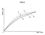
- the controlling part 17 records three kinds of gradation curves (G1 to G3) shown in Fig. 4 on a not-shown internal memory in advance.
- the controlling part 17 selects the gradation curve G1 shown in Fig. 4 .
- the gradation curve is the one used for a usual gradation conversion processing as same as that of a known technology.
- the gradation curve G1 has a gamma characteristic at a dark area side than a point P1, and a knee characteristic at a light area side than the point P1.
- the knee characteristic it is the same as that of the Japanese Unexamined Patent Application Publication No. 2006-287323 which is already applied by the present applicant.
- the knee characteristic of the gradation curve G1 enables the white washout of the light area (highlight area) to be suppressed.
- Step S6 according to the gradation curve G1 selected at Step S5, the controlling part 1 7 performs a gradation conversion processing on the image data which is subjected to the image processing at Step S3. Since the details of the gradation conversion processing are the same as those of a known technology, description thereof will be omitted. Then the controlling part 17 will proceed to Step S12 described later.
- Step S7 the controlling part 17 determines whether or not the gradation compression amount is "large”. If the controlling part 17 determines that the gradation compression amount is "large”, the controlling part 17 will proceed to Step S9 described later. On the contrary, if the controlling part 1 7 determines that the gradation compression amount is not "large” (the gradation compression amount is "small”), the controlling part 1 7 will proceed to Step S8.
- the controlling part 17 selects a gradation curve G2.
- the gradation curve G2 has the gamma characteristic in a dark area side than a point P2, and has the knee characteristic in a light area side than the point P2.
- the gradation curve G2 has a characteristic realizing a lower output level than that of the above mentioned gradation curve G1, with respect to an input level. Therefore, in the dark area of gradation, the gradation curve G2 has a gradient smaller than that of the gradation curve G1.
- the gradation curve G2 has a characteristic emphasizing contrast more than the gradation curve G1. Therefore, in the light area of gradation, the gradation curve G2 has a gradient larger than that of the gradation curve G1.
- the controlling part 17 selects a gradation curve G3.
- the gradation curve G3 has a characteristic having a gamma characteristic in the dark area side and a knee characteristic in the light area side continuously.
- the gradation curve G3 has a characteristic realizing a lower output level than the above mentioned gradation curve G2, with respect to an input level. Therefore, in the dark area of gradation, the gradation curve G3 has a gradient smaller than those of the gradation curves G1 and G2.
- the gradation curve G3 has a characteristic emphasizing contrast more than the gradation curves G1 and G2. Therefore, in the light area of gradation, the gradation curve G3 has a gradient larger than those of the gradation curves G1 and G2.
- Step S10 according to the gradation curve G2 selected at Step S8 or the gradation curve G3 selected at Step S9, the controlling part 1 7 performs a gradation conversion processing on the image data which is subjected to the imaging processing at Step S3. Since the details of the gradation conversion processing are the same as those of a known technology, description thereof will be omitted. Then the controlling part 1 7 will proceed to Step S1 1 described later.
- the gradation curve G2 or G3 is used, of which gradation is smaller than that of the usual gradation curve G1 in the dark area of gradation, and of which gradation is larger than that of the gradation curve G1 in the light area of gradation.
- a gradation conversion processing will be performed, which is relatively darker as a whole than the usual gradation conversion processing performed according to the usual gradation curve G1.
- the controlling part 17 performs a gradation compression processing on the image data which is subjected to the gradation conversion processing at Step S10.
- Fig. 5 is a view showing a parameter fg of gradation compression.
- the parameter fg has a gain depending on the lightness Y of an image, and as the lightness Y becomes smaller (as the neighboring range containing the image to be processed becomes darker), the parameter fg becomes larger. On the contrary, as the lightness Y becomes larger (as the neighboring range containing the image to be processed becomes lighter), the parameter fg becomes closer to 1.
- Step S10 when the gradation conversion processing is performed according to the gradation curve G2, the gradation conversion processing is performed using the parameter fg indicated by F2 in Fig. 5 . Moreover, at Step S10, when the gradation conversion processing is performed according to the gradation curve G3, the gradation conversion processing is performed using the parameter fg indicated by F3 in Fig. 5 .
- Y in Formula (1) to Formula (4) indicates the brightness value of a pixel to be noted.
- kr, kg and kb in Formula (1) are predetermined coefficients.
- Lpw in Formula (2) to Formula (4) is a low-pass filter around the pixel to be noted, and the low-pass filter has a characteristic shown in Fig. 6 .
- fg in Formula (2) to Formula (4) corresponds to the above mentioned parameter fg.
- the controlling part 17 records the image data subjected to the gradation compression processing at Step S11, or the image data subjected to the gradation conversion processing at Step S6, on the memory card 28 through the card interface 25, and completes a series of processing.
- the controlling part 1 7 may perform an image compression processing (JPEG compression processing etc.) on the image data through the compression and extension part 26, if necessary.
- the imaging apparatus has a first shooting mode in which correction of the dark area gradation of the image data is not performed and a second shooting mode in which the correction of the dark area gradation is performed, in a selectable manner.
- the gradation conversion processing is performed according to the first input-output characteristic
- the second shooting mode is selected, the gradation conversion processing is performed according to the second input-output characteristic which is different from the first input-output characteristic.
- the gradation conversion processing unit performs correction of improving the lightness of the dark area gradation of an image which is subjected to the gradation conversion processing. Therefore, an optimal gradation conversion processing can be performed as a previous step of performing correction of the dark area gradation.
- the second input-output characteristic is a characteristic realizing a lower output level than the first input-output characteristic with respect to the same input level in the dark area of gradation.
- the second input-output characteristic is defined by a gradation curve having a gradient smaller than that of the first input-output characteristic in the dark area of gradation. Therefore, since the resultant gradation conversion processing can be suppressed in a relatively dark state, the lightness of the whole image can be maintained before and after the gradation compression process.
- the second input-output characteristic in the light area of gradation, is a characteristic emphasizing contrast more than the first input-output characteristic.
- the second input-output characteristic in the light area of gradation, is defined by a gradation curve of which gradient is larger than that of the first input-output characteristic. Therefore, it is possible to improve the contrast of the highlight area while suppressing the white washout thereof. Therefore, a preferably drawn image can be generated.
- a configuration may be used, in which the gradation curve is determined by the controlling part 17 arbitrarily depending on the gradation compression amount. Such a configuration enables an optimal gradation conversion processing according to the gradation compression amount to be performed.
- a configuration may be used, in which the gradation compression amount is automatically determined by the controlling part 17.
- a configuration may be used, in which image data is segmented into a plurality of regions, difference in brightness between the maximum brightness region and the minimum brightness region is obtained, and the gradation compression amount is determined depending on the difference in brightness.
- a configuration may be used, in which the gradation compression amount is determined depending on the contrast of the light area.
- the gradation curve used for the gradation conversion processing is adjusted depending on the gradation compression amount
- a configuration may be used, in which the influence by exposure compensation is considered.
- the changing amount of the gradation curve used at the time of gradation compression may be set relatively small.
- a configuration may be used, in which only one of the both characteristics is changed.
- a configuration may be used, in which the gradient is smaller than that of the gradation curve G1 only in the dark area of gradation, and a configuration may be used, in which the gradient is larger than that of the gradation curve G1 only in the light area of gradation.
- a configuration may be used, in which gradation curves (the gradation curves G2 and G3) at the time of gradation compression processing are changed depending on photographic modes, such as, for example, a "portrait mode” and a “landscape mode", a configuration may be used, in which the gradation curves are changed depending on the strength of the contrast of an image, or a configuration may be used, in which the gradation curves are changed depending on the adjusting mode of the image.
- the present invention is not limited to this.
- the present invention can also be applied to a camera, such as a compact type electronic camera or a movie camera shooting a moving image, in a similar manner.
- the image processing apparatus described in the present embodiment may be realized in terms of software by a computer and an image processing program.
- a configuration may be used, in which a part or whole of the procedures after Step S4 described in the flowchart in Fig. 3 is realized by the computer.
- information such as information whether the mode is in a gradation compression mode or not, or information indicating the gradation compression amount should be supplied to the computer.
- Such information can be supplied to the computer by utilizing EXIF information etc. on image data.
- Such a configuration enables the same procedures as those of the present invention to be performed.
Abstract
Description
- The present invention relates to an imaging apparatus and an image processing program.
- Conventionally, there has been known a phenomenon that dark area gradation of image data is blacked out by shooting a subject having large difference in brightness. Therefore, in inventions of
Patent Document 1, the gradation is compressed by increasing the gain of the dark area gradation, and thereby the black-out of the dark area gradation is improved (for example, Japanese Patent No.2,663,189 - However, in the aforementioned inventions of
Patent Document 1, as the gradation of an image is compressed, the impression of the whole image will also be lighter. As a result, there was a problem in that the impression of lightness differs between an image subjected to a gradation compression processing and an image not subjected to the gradation compression processing, thus providing odd feeling to a user. Moreover, on the contrary of the aforementioned black-out of the dark area gradation, although a technology for improving the white washout of a highlight area by way of gradation compression has been considered, there was a problem in that suppression of the white washout reduces the contrast of the highlight area. - A proposition of an imaging apparatus and an image processing program of the present invention is to maintain lightness of a whole image, while improving contrast of a highlight area, at the time of correcting dark area gradation.
- In order to achieve the above-mentioned proposition, the imaging apparatus of the present invention, includes an image pickup unit picking up a subject image and generating image data, a selecting unit selecting any one of a first photographic mode that does not correct dark area gradation of the image data and a second photographic mode that corrects the dark area gradation of the image data, a gradation conversion processing unit performing a gradation conversion processing according to a first input-output characteristic when the first photographic mode is selected, and performing a gradation conversion processing according to a second input-output characteristic different from the first input-output characteristic when the second photographic mode is selected, and a correcting unit performing a correction of improving lightness of the dark area gradation of the image data subjected to the gradation conversion processing according to the second input-output characteristic by the gradation conversion processing unit when the second photographic mode is selected.
- In addition, preferably, in a dark area of gradation, the second input-output characteristic may have a characteristic realizing an output level which is lower than the output level of the first input-output characteristic, with respect to the same input level.
- Moreover, preferably, in the dark area of gradation, the second input-output characteristic may be defined by a gradation curve having a gradient smaller than that of the first input-output characteristic.
- Moreover, preferably, in a light area of gradation, the second input-output characteristic may have a characteristic emphasizing contrast more than the first input-output characteristic.
- Moreover, preferably, in the light area of gradation, the second input-output characteristic may be defined by a gradation curve having a gradient larger than that of the first input-output characteristic.
- Moreover, the imaging apparatus may further include an obtaining unit obtaining a lightness improvement amount of the dark area gradation by the correcting unit, wherein the gradation conversion processing unit selects any characteristic from among a plurality of predetermined input-output characteristics as the second input-output characteristic according to the lightness improvement amount, and performs the gradation conversion processing according to the selected input-output characteristic, and the correcting unit corrects the dark area gradation of the image data according to the lightness improvement amount.
- Moreover, the imaging apparatus may further include an obtaining unit obtaining a lightness improvement amount of dark area gradation by the correcting unit, wherein the gradation conversion processing unit determines the second input-output characteristic according to the lightness improvement amount, and performs the gradation conversion processing according to the determined input-output characteristic, and the correcting unit corrects the dark area gradation of the image data according to the lightness improvement amount.
- Moreover, an image processing program for causing a computer to realize an image processing with respect to the image data to be processed, in which the configuration regarding the above invention is expressed by converting the configuration into the program, is also effective as a specific embodiment of the present invention.
-
-
Fig. 1 is a view showing a configuration of anelectronic camera 1 in accordance with the present embodiment. -
Fig. 2 is a functional block diagram of theelectronic camera 1 in accordance with the present embodiment. -
Fig. 3 is a flow chart showing operation at the time of shooting of theelectronic camera 1 in accordance with the present embodiment. -
Fig. 4 is a view illustrating a gradation curve. -
Fig. 5 is a view illustrating a parameter fg of gradation compression. -
Fig. 6 is a view illustrating a low-pass filter. - Hereinafter, with reference to drawings, an embodiment of the present invention will be described. In the following embodiment, a single lens reflex type electronic camera will be described as an example.
-
Fig. 1 is a figure showing a configuration of anelectronic camera 1 of the present embodiment. As shown inFig. 1 , theelectronic camera 1 includes the following parts aphotographic lens 2, anaperture diaphragm 3, aquick return mirror 4, asub mirror 5, adiffusion screen 6, acondenser lens 7, apentaprism 8, abeam splitter 9, anocular lens 10, animaging lens 11, anAE sensor 12, a shutter 13, an image-capturing sensor 14, and afocus detecting part 15. - The
AE sensor 12 is, for example, a 5-way split photometric sensor. The image-capturingsensor 14 is a semiconductor device, such as a CCD (Charge Coupled Device), or a CMOS (Complementary Metal Oxide Semiconductor). Thefocus detecting part 15 performs focus detection in a scheme of, for example, phase difference to detect the focused state of thephotographic lens 2. Moreover, theelectronic camera 1 performs focus detection in a contrast scheme based on the brightness detected by theAE sensor 12, to detect the focused state of thephotographic lens 2. It is preferable that whether the focus detection in a phase difference scheme or the focus detection in a contrast scheme should be performed can be set depending on operation of a user. Moreover, a configuration in which the focused state of thephotographic lens 2 is detected by the combination of the focus detection in a phase difference scheme or the focus detection in a contrast scheme, may also be used. - Moreover, the
electronic camera 1 further includes amonitor 16 such as a liquid crystal display monitor displaying an image etc. generated by way of image pick-up, and a controllingpart 1 7 that controls each of the parts. The controllingpart 1 7 includes a not-shown memory inside thereof, and preliminarily records programs for controlling each of the parts. - At the time of non shooting, that is when shooting is not performed, as shown in
Fig. 1 , thequick return mirror 4 is arranged at an angle of 45°. Light flux which passed through thephotographic lens 2 and theaperture diaphragm 3, is then reflected by thequick return mirror 4 to be led to theocular lens 10 through thediffusion screen 6, thecondenser lens 7, thepentaprism 8, and thebeam splitter 9. A user confirms a construct by viewing the subject image through theocular lens 10. On the other hand, light flux which is divided upward by thebeam splitter 9, is re-imaged on the image pick-up plane of theAE sensor 12 through theimaging lens 11. Moreover, light flux which passed through thequick return mirror 4, is led to thefocus detecting part 15 through thesub mirror 5. - On the other hand, at the time of shooting, the
quick return mirror 4 is evacuated to a position shown by a dashed line to open the shutter 13, and the light flux from thephotographic lens 2 is led to the image-capturingsensor 14. -
Fig. 2 is a functional block diagram of theelectronic camera 1 of the present embodiment. As shown inFig. 2 , in addition to the configuration inFig. 1 , theelectronic camera 1 includes the following parts: atiming generator 20, asignal processing part 21, an A/D converting part 22, abuffer memory 23, abus 24, acard interface 25, a compression andextension part 26, and animage displaying part 27. Thetiming generator 20 supplies an output pulse to the image-capturingsensor 14. Moreover, the image data generated by the image-capturingsensor 14 is temporarily stored on thebuffer memory 23 through the signal processing part 21 (an adjusting part of gain corresponding to image pick-up sensitivity is included), and the A/D converting part 22. Thebuffer memory 23 is coupled to thebus 24. Thecard interface 25, the controllingpart 17 described inFig. 1 , the compression andextension part 26, and theimage displaying part 27 are coupled to thebus 24. Thecard interface 25 is coupled to a detachable memory card 28 and records image data on the memory card 28. Moreover, switch members 29 (not-shown release buttons and the like are included) of theelectronic camera 1, thetiming generator 20, and theAE sensor 12 are coupled to the controllingpart 17. Further, theimage displaying part 27 displays an image or the like on themonitor 16 disposed on the back surface of theelectronic camera 1. - Moreover, the
electronic camera 1 includes a gradation non-compression mode in which the dark area gradation of image data is not corrected and a gradation compression mode in which the dark area gradation of image data is corrected. In which mode shooting is performed, is selected in advance by a user through theswitch members 29. Moreover, in the gradation compression mode, the magnitude of gradation compression amount (lightness improvement amount) can be set into two stages (large/small). The setting is also performed in advance by the user through theswitch members 29. - The operation at the time of shooting of the
electronic camera 1 having a configuration mentioned above will be described with reference to a flow chart shown inFig. 3 . - At Step S1, the controlling
part 17 determines whether or not start of shooting is indicated by the user through theswitch members 29. Then, if the controllingpart 17 determines that the start of shooting is indicated, the controllingpart 1 7 will proceed to Step S2. - At Step S2, the controlling
part 17 controls each of the parts, and picks up a subject image by the image-capturingsensor 14 and generate image data. The image data generated by the image-capturingsensor 14 is temporarily memorized on thebuffer memory 23 through thesignal processing part 21 and the A/D converting part 22. - At Step S3, the controlling
part 17 reads out the image data from thebuffer memory 23, and performs usual image processing. The usual image processing is a process, such as white balance adjustment, interpolation processing, or color tone correction processing. Since the specific method of each processing is the same as that of a known technology, description thereof will be omitted. - At Step S4, the controlling
part 17 determines whether or not the gradation compression mode is selected. Then, if thecontrolling part 17 determines that the gradation compression mode is selected, thecontrolling part 1 7 will proceed to Step S6. On the contrary, if thecontrolling part 1 7 determines that the gradation compression mode is not selected (gradation non-compression mode is selected), thecontrolling part 1 7 will proceed to Step S5. - At Step S5, the controlling
part 17 selects the gradation curve G1. The gradation curve is used for gradation conversion processing performed at below mentioned Step S6 or Step S10. The controllingpart 17 records three kinds of gradation curves (G1 to G3) shown inFig. 4 on a not-shown internal memory in advance. - In the gradation non-compression mode, the controlling
part 17 selects the gradation curve G1 shown inFig. 4 . The gradation curve is the one used for a usual gradation conversion processing as same as that of a known technology. However, as shown inFig. 4 , the gradation curve G1 has a gamma characteristic at a dark area side than a point P1, and a knee characteristic at a light area side than the point P1. Regarding the knee characteristic, it is the same as that of the Japanese Unexamined Patent Application Publication No.2006-287323 - At Step S6, according to the gradation curve G1 selected at Step S5, the
controlling part 1 7 performs a gradation conversion processing on the image data which is subjected to the image processing at Step S3. Since the details of the gradation conversion processing are the same as those of a known technology, description thereof will be omitted. Then the controllingpart 17 will proceed to Step S12 described later. - At Step S7, the controlling
part 17 determines whether or not the gradation compression amount is "large". If the controllingpart 17 determines that the gradation compression amount is "large", the controllingpart 17 will proceed to Step S9 described later. On the contrary, if thecontrolling part 1 7 determines that the gradation compression amount is not "large" (the gradation compression amount is "small"), thecontrolling part 1 7 will proceed to Step S8. - At Step S8, the controlling
part 17 selects a gradation curve G2. As shown inFig. 4 , the gradation curve G2 has the gamma characteristic in a dark area side than a point P2, and has the knee characteristic in a light area side than the point P2. However, in the dark area of gradation, the gradation curve G2 has a characteristic realizing a lower output level than that of the above mentioned gradation curve G1, with respect to an input level. Therefore, in the dark area of gradation, the gradation curve G2 has a gradient smaller than that of the gradation curve G1. Moreover, in the light area of gradation, the gradation curve G2 has a characteristic emphasizing contrast more than the gradation curve G1. Therefore, in the light area of gradation, the gradation curve G2 has a gradient larger than that of the gradation curve G1. - At Step S9, the controlling
part 17 selects a gradation curve G3. As shown inFig. 4 , the gradation curve G3 has a characteristic having a gamma characteristic in the dark area side and a knee characteristic in the light area side continuously. However, in the dark area of gradation, the gradation curve G3 has a characteristic realizing a lower output level than the above mentioned gradation curve G2, with respect to an input level. Therefore, in the dark area of gradation, the gradation curve G3 has a gradient smaller than those of the gradation curves G1 and G2. Moreover, in the light area of gradation, the gradation curve G3 has a characteristic emphasizing contrast more than the gradation curves G1 and G2. Therefore, in the light area of gradation, the gradation curve G3 has a gradient larger than those of the gradation curves G1 and G2. - At Step S10, according to the gradation curve G2 selected at Step S8 or the gradation curve G3 selected at Step S9, the
controlling part 1 7 performs a gradation conversion processing on the image data which is subjected to the imaging processing at Step S3. Since the details of the gradation conversion processing are the same as those of a known technology, description thereof will be omitted. Then thecontrolling part 1 7 will proceed to StepS1 1 described later. - In the gradation conversion processing at Step S10, as shown in
Fig. 4 , the gradation curve G2 or G3 is used, of which gradation is smaller than that of the usual gradation curve G1 in the dark area of gradation, and of which gradation is larger than that of the gradation curve G1 in the light area of gradation. As a result, a gradation conversion processing will be performed, which is relatively darker as a whole than the usual gradation conversion processing performed according to the usual gradation curve G1. Moreover, it is possible to improve the contrast in the highlight area while suppressing the white washout thereof. - At Step S11, the controlling
part 17 performs a gradation compression processing on the image data which is subjected to the gradation conversion processing at Step S10. -
Fig. 5 is a view showing a parameter fg of gradation compression. As shown inFig. 5 , the parameter fg has a gain depending on the lightness Y of an image, and as the lightness Y becomes smaller (as the neighboring range containing the image to be processed becomes darker), the parameter fg becomes larger. On the contrary, as the lightness Y becomes larger (as the neighboring range containing the image to be processed becomes lighter), the parameter fg becomes closer to 1. In addition, F2 inFig. 5 indicates the parameter fg when the magnitude of the gradation compression amount is "small", and F3 indicates the parameter fg when the magnitude of the gradation compression amount is "large." That is, at Step S10, when the gradation conversion processing is performed according to the gradation curve G2, the gradation conversion processing is performed using the parameter fg indicated by F2 inFig. 5 . Moreover, at Step S10, when the gradation conversion processing is performed according to the gradation curve G3, the gradation conversion processing is performed using the parameter fg indicated by F3 inFig. 5 . - Gradation compression operations of each of pixels R[x, y], G[x, y] and B[x, y] are performed by the following Formula (1) to Formula (4).


- Where, Y in Formula (1) to Formula (4) indicates the brightness value of a pixel to be noted. Moreover, kr, kg and kb in Formula (1) are predetermined coefficients. Moreover, Lpw in Formula (2) to Formula (4) is a low-pass filter around the pixel to be noted, and the low-pass filter has a characteristic shown in
Fig. 6 . Moreover, fg in Formula (2) to Formula (4) corresponds to the above mentioned parameter fg. - At Step S12, the controlling
part 17 records the image data subjected to the gradation compression processing at Step S11, or the image data subjected to the gradation conversion processing at Step S6, on the memory card 28 through thecard interface 25, and completes a series of processing. In addition, before recording the image data on the memory card 28, thecontrolling part 1 7 may perform an image compression processing (JPEG compression processing etc.) on the image data through the compression andextension part 26, if necessary. - As described above, in accordance with the present embodiment, the imaging apparatus has a first shooting mode in which correction of the dark area gradation of the image data is not performed and a second shooting mode in which the correction of the dark area gradation is performed, in a selectable manner. When the first shooting mode is selected, the gradation conversion processing is performed according to the first input-output characteristic, and when the second shooting mode is selected, the gradation conversion processing is performed according to the second input-output characteristic which is different from the first input-output characteristic. When the second shooting mode is selected, according to the second input-output characteristic, the gradation conversion processing unit performs correction of improving the lightness of the dark area gradation of an image which is subjected to the gradation conversion processing. Therefore, an optimal gradation conversion processing can be performed as a previous step of performing correction of the dark area gradation.
- Moreover, in accordance with the present embodiment, the second input-output characteristic is a characteristic realizing a lower output level than the first input-output characteristic with respect to the same input level in the dark area of gradation. Moreover, in accordance with the present embodiment, the second input-output characteristic is defined by a gradation curve having a gradient smaller than that of the first input-output characteristic in the dark area of gradation. Therefore, since the resultant gradation conversion processing can be suppressed in a relatively dark state, the lightness of the whole image can be maintained before and after the gradation compression process.
- Moreover, in accordance with the present embodiment, in the light area of gradation, the second input-output characteristic is a characteristic emphasizing contrast more than the first input-output characteristic. Moreover, in accordance with the present embodiment, in the light area of gradation, the second input-output characteristic is defined by a gradation curve of which gradient is larger than that of the first input-output characteristic. Therefore, it is possible to improve the contrast of the highlight area while suppressing the white washout thereof. Therefore, a preferably drawn image can be generated.
- Moreover, in accordance with the present embodiment any one selected from among predetermined plurality of input-output characteristics as the second input-output characteristic, according to the lightness improvement amount of the dark area gradation, a gradation conversion processing is performed according to the selected input-output characteristic, and the dark area gradation of image data is corrected according to the lightness improvement amount. Therefore, an optimal gradation conversion processing depending on the lightness improvement amount of dark area gradation can be performed.
- In addition, in accordance with the present embodiment, an example is shown, in which any one selected from among the plurality of gradation curves (gradation curves G1 to G3) shown in
Fig. 4 is used, however, a configuration may be used, in which the gradation curve is determined by the controllingpart 17 arbitrarily depending on the gradation compression amount. Such a configuration enables an optimal gradation conversion processing according to the gradation compression amount to be performed. - Moreover, in accordance with the present embodiment, although an example is shown, in which the magnitude of the gradation compression amount (lightness improvement amount) can be set into two stages (large/small), a configuration may be used, in which the gradation compression amount is automatically determined by the controlling
part 17. For example, a configuration may be used, in which image data is segmented into a plurality of regions, difference in brightness between the maximum brightness region and the minimum brightness region is obtained, and the gradation compression amount is determined depending on the difference in brightness. Moreover, a configuration may be used, in which the gradation compression amount is determined depending on the contrast of the light area. - Moreover, in the present embodiment, although an example is shown, in which the gradation curve used for the gradation conversion processing is adjusted depending on the gradation compression amount, a configuration may be used, in which the influence by exposure compensation is considered. For example, when the lightness of the whole image can be maintained to some extent byway of exposure compensation, the changing amount of the gradation curve used at the time of gradation compression may be set relatively small.
- Moreover, in the present embodiment, as described in
Fig. 4 , although an example is shown, in which characteristics of both of the light area and the black area of gradation curves (G2 and G3) at the time of gradation compression are changed with respect to the gradation curve (G1) at the time of non-compression, a configuration may be used, in which only one of the both characteristics is changed. For example, a configuration may be used, in which the gradient is smaller than that of the gradation curve G1 only in the dark area of gradation, and a configuration may be used, in which the gradient is larger than that of the gradation curve G1 only in the light area of gradation. Further a configuration may be used, in which gradation curves (the gradation curves G2 and G3) at the time of gradation compression processing are changed depending on photographic modes, such as, for example, a "portrait mode" and a "landscape mode", a configuration may be used, in which the gradation curves are changed depending on the strength of the contrast of an image, or a configuration may be used, in which the gradation curves are changed depending on the adjusting mode of the image. - Moreover, in the above-mentioned embodiment, an example is described, in which the technology of the present invention is realized in an electronic camera. However, the present invention is not limited to this. For example, the present invention can also be applied to a camera, such as a compact type electronic camera or a movie camera shooting a moving image, in a similar manner.
- Moreover, the image processing apparatus described in the present embodiment may be realized in terms of software by a computer and an image processing program. In this case, a configuration may be used, in which a part or whole of the procedures after Step S4 described in the flowchart in
Fig. 3 is realized by the computer. In order to realize the image processing apparatus by the computer, together with the image data, information such as information whether the mode is in a gradation compression mode or not, or information indicating the gradation compression amount should be supplied to the computer. Such information can be supplied to the computer by utilizing EXIF information etc. on image data. Such a configuration enables the same procedures as those of the present invention to be performed. - In addition, the present invention can be performed in various other forms, without departing from the spirit or the main features thereof. Therefore, at all points, the above-mentioned embodiment example is only mere illustration, and should not be interpreted restrictively. The scope of the present invention is indicated by the appended claims, and not restricted by the description of the specification at all. Further, modifications and changes belonging to the scope equivalent to the scope of the claims, are all falling within the scope of the present invention.
- The many features and advantages of the embodiments are apparent from the detailed specification and, thus, it is intended by the appended claims to cover all such features and advantages of the embodiments that fall within the true spirit and scope thereof. Further, since numerous modifications and changes will readily occur to those skilled in the art, it is not desired to limit the inventive embodiments to the exact construction and operation illustrated and described, and accordingly all suitable modifications and equivalents may be resorted to, falling within the scope thereof.
Claims (14)
- An imaging apparatus, comprising:an image pickup unit picking up a subject image and generating image data;a selecting unit selecting any one of a first photographic mode that does not correct dark area gradation of said image data and a second photographic mode that corrects the dark area gradation of said image data;a gradation conversion processing unit performing a gradation conversion processing according to a first input-output characteristic when said first photographic mode is selected, and performing a gradation conversion processing according to a second input-output characteristic different from said first input-output characteristic when said second photographic mode is selected; anda correcting unit performing a correction of improving lightness of the dark area gradation of said image data subjected to the gradation conversion processing according to said second input-output characteristic by said gradation conversion processing unit when said second photographic mode is selected.
- The imaging apparatus according to Claim 1, wherein
in a dark area of gradation, said second input-output characteristic is a characteristic realizing a lower output level than the output level of said first input-output characteristic, with respect to the same input level. - The imaging apparatus according to Claim 2, wherein
in the dark area of gradation, said second input-output characteristic is defined by a gradation curve having a gradient smaller than that of said first input-output characteristic. - The imaging apparatus according to Claim 1, wherein
in a light area of gradation, said second input-output characteristic is a characteristic emphasizing contrast more than said first input-output characteristic. - The imaging apparatus according to Claim 4, wherein
in the light area of gradation, said second input-output characteristic is defined by a gradation curve having a gradient larger than that of said first input-output characteristic. - The imaging apparatus according to Claim 1, further comprising:an obtaining unit obtaining a lightness improvement amount of the dark area gradation by said correcting unit; whereinsaid gradation conversion processing unit selects any characteristic from among a plurality of predetermined input-output characteristics as said second input-output characteristic according to said lightness improvement amount, and performs said gradation conversion processing according to the selected input-output characteristic; andsaid correcting unit corrects the dark area gradation of said image data according to said lightness improvement amount.
- The imaging apparatus according to Claim 1, further comprising:an obtaining unit obtaining a lightness improvement amount of dark area gradation by said correcting unit; whereinsaid gradation conversion processing unit determines said second input-output characteristic according to said lightness improvement amount, and performs said gradation conversion processing according to the determined input-output characteristic; andsaid correcting unit corrects the dark area gradation of said image data according to said lightness improvement amount.
- An image processing program adapted to realizing an image processing with respect to image data to be processed when being executed on a computer, the program comprising the operations of:obtaining said image data and information indicating in which mode said image data is generated between a first photographic mode that does not correct dark area gradation of said image data and a second photographic mode that corrects the dark area gradation of said image data;performing a gradation conversion processing according to a first input-output characteristic when said image data is generated in said first photographic mode, and performing a gradation conversion processing according to a second input-output characteristic different from said first input-output characteristic when said image data is generated in said second photographic mode; andperforming correction of improving lightness of the dark area gradation of said image data subjected to a gradation conversion processing according to said second input-output characteristic at said gradation conversion processing operation, when said image data is generated in said second photographic mode.
- The image processing program according to Claim 8, wherein
in the dark area of gradation, said second input-output characteristic is a characteristic realizing a lower output level than the output level of said first input-output characteristic, with respect to the same input level. - The image processing program according to Claim 9, wherein
in the dark area of gradation, said second input-output characteristic is defined by a gradation curve having a gradient smaller than that of said first input-output characteristic. - The image processing program according to Claim 8, wherein
in a light area of gradation, said second input-output characteristic is a characteristic emphasizing contrast more than said first input-output characteristic. - The image processing program according to Claim 11, wherein
in the light area of gradation, said second input-output characteristic is defined by a gradation curve having a gradient larger than that of said first input-output characteristic. - The image processing program according to Claim 8, wherein:at said obtaining operation, a lightness improvement amount of the dark area gradation at said correcting operation is further obtained;at said gradation conversion processing operation, any input-output characteristic from among a plurality of predetermined input-output characteristics is selected as said second input-output characteristic according to said lightness improvement amount, and said gradation conversion processing is performed according to the selected input-output characteristic; andat said correcting operation, the dark area gradation of said image data is corrected according to said lightness improvement amount.
- The image processing program according to Claim 8, wherein:at said obtaining operation, a lightness improvement amount of the dark area gradation at said correcting operation is further obtained;at said gradation conversion processing operation, said second input-output characteristic is determined according to said lightness improvement amount, and said gradation conversion processing is performed according to the determined input-output characteristic; andat said correcting operation, the dark area gradation of said image data is corrected according to said lightness improvement amount.
Applications Claiming Priority (1)
| Application Number | Priority Date | Filing Date | Title |
|---|---|---|---|
| JP2007147327A JP5076650B2 (en) | 2007-06-01 | 2007-06-01 | Imaging apparatus and image processing program |
Publications (3)
| Publication Number | Publication Date |
|---|---|
| EP1998552A2 true EP1998552A2 (en) | 2008-12-03 |
| EP1998552A3 EP1998552A3 (en) | 2012-01-25 |
| EP1998552B1 EP1998552B1 (en) | 2017-03-15 |
Family
ID=39745004
Family Applications (1)
| Application Number | Title | Priority Date | Filing Date |
|---|---|---|---|
| EP08251879.6A Expired - Fee Related EP1998552B1 (en) | 2007-06-01 | 2008-05-19 | Imaging apparatus and image processing program |
Country Status (3)
| Country | Link |
|---|---|
| US (1) | US9019406B2 (en) |
| EP (1) | EP1998552B1 (en) |
| JP (1) | JP5076650B2 (en) |
Cited By (1)
| Publication number | Priority date | Publication date | Assignee | Title |
|---|---|---|---|---|
| GB2543644A (en) * | 2015-09-25 | 2017-04-26 | Canon Kk | Image sensor, imaging method, and imaging apparatus |
Families Citing this family (6)
| Publication number | Priority date | Publication date | Assignee | Title |
|---|---|---|---|---|
| JP4941424B2 (en) * | 2008-07-17 | 2012-05-30 | 株式会社ニコン | Imaging apparatus and image processing program |
| WO2010007726A1 (en) * | 2008-07-17 | 2010-01-21 | 株式会社ニコン | Imaging device, image processing program, image processing device, and image processing method |
| JP4868040B2 (en) * | 2009-08-20 | 2012-02-01 | 株式会社ニコン | Image processing apparatus, electronic camera, and image processing program |
| US8665351B2 (en) | 2009-07-23 | 2014-03-04 | Nikon Corporation | Image processing device, electronic camera, and storage medium storing image processing program |
| JP5460909B2 (en) * | 2013-04-12 | 2014-04-02 | キヤノン株式会社 | Imaging apparatus and image processing method |
| JP6834134B2 (en) * | 2016-01-21 | 2021-02-24 | オムロン株式会社 | Imaging device and information code reader |
Citations (2)
| Publication number | Priority date | Publication date | Assignee | Title |
|---|---|---|---|---|
| JP2663189B2 (en) | 1990-01-29 | 1997-10-15 | 富士写真フイルム株式会社 | Image dynamic range compression processing method |
| JP2006287323A (en) | 2005-03-31 | 2006-10-19 | Nikon Corp | Imaging apparatus |
Family Cites Families (12)
| Publication number | Priority date | Publication date | Assignee | Title |
|---|---|---|---|---|
| DE69414153T2 (en) * | 1993-02-24 | 1999-06-10 | Matsushita Electric Ind Co Ltd | Device for gradation correction and image recording device with such a device |
| JPH0823461A (en) * | 1994-07-06 | 1996-01-23 | Sony Corp | Video camera |
| DE69737984T2 (en) * | 1996-06-12 | 2008-04-30 | Fujifilm Corp. | Image processing method and apparatus |
| US6449390B1 (en) * | 1997-09-24 | 2002-09-10 | Canon Kabushiki Kaisha | Image processing apparatus and method therefor |
| US7088390B2 (en) * | 2000-06-19 | 2006-08-08 | Olympus Optical Co., Ltd. | Imaging apparatus in which exposure control is performed to suppress changes in sensitivity due to changes in gradation mode |
| JP4269699B2 (en) * | 2003-01-24 | 2009-05-27 | 株式会社ニコン | Electronic camera |
| JP2006080960A (en) * | 2004-09-10 | 2006-03-23 | Konica Minolta Photo Imaging Inc | Image pickup device and method |
| JP2006114005A (en) * | 2004-09-17 | 2006-04-27 | Nikon Corp | Gradation conversion apparatus, program, electronic camera, and method therefor |
| JP4277773B2 (en) * | 2004-09-21 | 2009-06-10 | 株式会社日立製作所 | Video display device |
| JP2007027967A (en) * | 2005-07-13 | 2007-02-01 | Fujifilm Holdings Corp | Photographing apparatus |
| US7791656B2 (en) * | 2005-08-16 | 2010-09-07 | Konica Minolta Holdings, Inc. | Image sensing apparatus and image processing method |
| JP4240023B2 (en) * | 2005-08-31 | 2009-03-18 | ソニー株式会社 | Imaging apparatus, imaging method and imaging program, and image processing apparatus, image processing method and image processing program |
-
2007
- 2007-06-01 JP JP2007147327A patent/JP5076650B2/en not_active Expired - Fee Related
-
2008
- 2008-05-14 US US12/153,136 patent/US9019406B2/en not_active Expired - Fee Related
- 2008-05-19 EP EP08251879.6A patent/EP1998552B1/en not_active Expired - Fee Related
Patent Citations (2)
| Publication number | Priority date | Publication date | Assignee | Title |
|---|---|---|---|---|
| JP2663189B2 (en) | 1990-01-29 | 1997-10-15 | 富士写真フイルム株式会社 | Image dynamic range compression processing method |
| JP2006287323A (en) | 2005-03-31 | 2006-10-19 | Nikon Corp | Imaging apparatus |
Cited By (3)
| Publication number | Priority date | Publication date | Assignee | Title |
|---|---|---|---|---|
| GB2543644A (en) * | 2015-09-25 | 2017-04-26 | Canon Kk | Image sensor, imaging method, and imaging apparatus |
| GB2543644B (en) * | 2015-09-25 | 2020-04-08 | Canon Kk | Image sensor, imaging method, and imaging apparatus |
| US10735678B2 (en) | 2015-09-25 | 2020-08-04 | Canon Kabushiki Kaisha | Image sensor, imaging method, and imaging apparatus |
Also Published As
| Publication number | Publication date |
|---|---|
| JP5076650B2 (en) | 2012-11-21 |
| JP2008301371A (en) | 2008-12-11 |
| EP1998552A3 (en) | 2012-01-25 |
| US20080297632A1 (en) | 2008-12-04 |
| EP1998552B1 (en) | 2017-03-15 |
| US9019406B2 (en) | 2015-04-28 |
Similar Documents
| Publication | Publication Date | Title |
|---|---|---|
| KR100819804B1 (en) | Photographing apparatus | |
| US7876367B2 (en) | Imaging apparatus | |
| US8294795B2 (en) | Image capturing apparatus and medium storing image processing program | |
| EP1998552B1 (en) | Imaging apparatus and image processing program | |
| EP3293697A1 (en) | Image processing device, imaging device, image processing method, and storage medium storing image processing program for image processing device | |
| US8989510B2 (en) | Contrast enhancement using gradation conversion processing | |
| JP2007329619A (en) | Video signal processor, video signal processing method and video signal processing program | |
| US8570407B2 (en) | Imaging apparatus, image processing program, image processing apparatus, and image processing method | |
| JP5526950B2 (en) | Image processing apparatus and method, and imaging apparatus | |
| US8102446B2 (en) | Image capturing system and image processing method for applying grayscale conversion to a video signal, and computer-readable recording medium having recorded thereon an image processing program for applying grayscale conversion to a video signal | |
| JP2006253970A (en) | Imaging apparatus, shading correction data generating method, and program | |
| JP4883057B2 (en) | Image processing program, image processing apparatus, and image processing method | |
| JP4857856B2 (en) | Electronic camera having saturation adjustment function and image processing program | |
| JP5561389B2 (en) | Image processing program, image processing apparatus, electronic camera, and image processing method | |
| JP4941424B2 (en) | Imaging apparatus and image processing program | |
| JP5217783B2 (en) | Imaging device | |
| US8665351B2 (en) | Image processing device, electronic camera, and storage medium storing image processing program | |
| JP5307572B2 (en) | Imaging system, video signal processing program, and imaging method | |
| JP4868040B2 (en) | Image processing apparatus, electronic camera, and image processing program | |
| JP4978669B2 (en) | Image processing apparatus, electronic camera, and image processing program | |
| US8106977B2 (en) | Image capturing system and image processing method for applying grayscale conversion to a video signal, and computer-readable recording medium having recorded thereon an image processing program for applying grayscale conversion to a video signal | |
| JP5208799B2 (en) | Imaging system, video signal processing program, and imaging method | |
| JP2010193112A (en) | Image processing apparatus and digital still camera | |
| JP2012105354A (en) | Image processing apparatus, electronic camera, and image processing program |
Legal Events
| Date | Code | Title | Description |
|---|---|---|---|
| PUAI | Public reference made under article 153(3) epc to a published international application that has entered the european phase |
Free format text: ORIGINAL CODE: 0009012 |
|
| AK | Designated contracting states |
Kind code of ref document: A2 Designated state(s): AT BE BG CH CY CZ DE DK EE ES FI FR GB GR HR HU IE IS IT LI LT LU LV MC MT NL NO PL PT RO SE SI SK TR |
|
| AX | Request for extension of the european patent |
Extension state: AL BA MK RS |
|
| RAP1 | Party data changed (applicant data changed or rights of an application transferred) |
Owner name: NIKON CORPORATION |
|
| PUAL | Search report despatched |
Free format text: ORIGINAL CODE: 0009013 |
|
| AK | Designated contracting states |
Kind code of ref document: A3 Designated state(s): AT BE BG CH CY CZ DE DK EE ES FI FR GB GR HR HU IE IS IT LI LT LU LV MC MT NL NO PL PT RO SE SI SK TR |
|
| AX | Request for extension of the european patent |
Extension state: AL BA MK RS |
|
| RIC1 | Information provided on ipc code assigned before grant |
Ipc: H04N 5/243 20060101ALI20111222BHEP Ipc: H04N 5/20 20060101AFI20111222BHEP Ipc: H04N 5/202 20060101ALI20111222BHEP Ipc: H04N 5/232 20060101ALI20111222BHEP |
|
| 17P | Request for examination filed |
Effective date: 20120724 |
|
| AKX | Designation fees paid |
Designated state(s): DE FR GB |
|
| RAP1 | Party data changed (applicant data changed or rights of an application transferred) |
Owner name: NIKON CORPORATION |
|
| 17Q | First examination report despatched |
Effective date: 20160104 |
|
| REG | Reference to a national code |
Ref country code: DE Ref legal event code: R079 Ref document number: 602008049195 Country of ref document: DE Free format text: PREVIOUS MAIN CLASS: H04N0005200000 Ipc: H04N0101000000 |
|
| GRAP | Despatch of communication of intention to grant a patent |
Free format text: ORIGINAL CODE: EPIDOSNIGR1 |
|
| RIC1 | Information provided on ipc code assigned before grant |
Ipc: H04N 5/243 20060101ALI20160912BHEP Ipc: H04N 101/00 20060101AFI20160912BHEP Ipc: H04N 5/202 20060101ALI20160912BHEP |
|
| INTG | Intention to grant announced |
Effective date: 20160926 |
|
| STAA | Information on the status of an ep patent application or granted ep patent |
Free format text: STATUS: GRANT OF PATENT IS INTENDED |
|
| GRAS | Grant fee paid |
Free format text: ORIGINAL CODE: EPIDOSNIGR3 |
|
| GRAA | (expected) grant |
Free format text: ORIGINAL CODE: 0009210 |
|
| STAA | Information on the status of an ep patent application or granted ep patent |
Free format text: STATUS: THE PATENT HAS BEEN GRANTED |
|
| AK | Designated contracting states |
Kind code of ref document: B1 Designated state(s): DE FR GB |
|
| REG | Reference to a national code |
Ref country code: GB Ref legal event code: FG4D |
|
| REG | Reference to a national code |
Ref country code: DE Ref legal event code: R096 Ref document number: 602008049195 Country of ref document: DE Ref country code: FR Ref legal event code: PLFP Year of fee payment: 10 |
|
| REG | Reference to a national code |
Ref country code: DE Ref legal event code: R097 Ref document number: 602008049195 Country of ref document: DE |
|
| PLBE | No opposition filed within time limit |
Free format text: ORIGINAL CODE: 0009261 |
|
| STAA | Information on the status of an ep patent application or granted ep patent |
Free format text: STATUS: NO OPPOSITION FILED WITHIN TIME LIMIT |
|
| 26N | No opposition filed |
Effective date: 20171218 |
|
| REG | Reference to a national code |
Ref country code: FR Ref legal event code: PLFP Year of fee payment: 11 |
|
| REG | Reference to a national code |
Ref country code: DE Ref legal event code: R082 Ref document number: 602008049195 Country of ref document: DE Representative=s name: MAUCHER JENKINS PATENTANWAELTE & RECHTSANWAELT, DE |
|
| PGFP | Annual fee paid to national office [announced via postgrant information from national office to epo] |
Ref country code: DE Payment date: 20210420 Year of fee payment: 14 Ref country code: FR Payment date: 20210412 Year of fee payment: 14 |
|
| PGFP | Annual fee paid to national office [announced via postgrant information from national office to epo] |
Ref country code: GB Payment date: 20210422 Year of fee payment: 14 |
|
| REG | Reference to a national code |
Ref country code: DE Ref legal event code: R119 Ref document number: 602008049195 Country of ref document: DE |
|
| GBPC | Gb: european patent ceased through non-payment of renewal fee |
Effective date: 20220519 |
|
| PG25 | Lapsed in a contracting state [announced via postgrant information from national office to epo] |
Ref country code: FR Free format text: LAPSE BECAUSE OF NON-PAYMENT OF DUE FEES Effective date: 20220531 |
|
| PG25 | Lapsed in a contracting state [announced via postgrant information from national office to epo] |
Ref country code: GB Free format text: LAPSE BECAUSE OF NON-PAYMENT OF DUE FEES Effective date: 20220519 Ref country code: DE Free format text: LAPSE BECAUSE OF NON-PAYMENT OF DUE FEES Effective date: 20221201 |