EP2000424A2 - Medicine cart - Google Patents
Medicine cart Download PDFInfo
- Publication number
- EP2000424A2 EP2000424A2 EP07738661A EP07738661A EP2000424A2 EP 2000424 A2 EP2000424 A2 EP 2000424A2 EP 07738661 A EP07738661 A EP 07738661A EP 07738661 A EP07738661 A EP 07738661A EP 2000424 A2 EP2000424 A2 EP 2000424A2
- Authority
- EP
- European Patent Office
- Prior art keywords
- unlocking
- medicine
- cassette
- pressing member
- lever
- Prior art date
- Legal status (The legal status is an assumption and is not a legal conclusion. Google has not performed a legal analysis and makes no representation as to the accuracy of the status listed.)
- Withdrawn
Links
Images


Classifications
-
- A—HUMAN NECESSITIES
- A61—MEDICAL OR VETERINARY SCIENCE; HYGIENE
- A61G—TRANSPORT, PERSONAL CONVEYANCES, OR ACCOMMODATION SPECIALLY ADAPTED FOR PATIENTS OR DISABLED PERSONS; OPERATING TABLES OR CHAIRS; CHAIRS FOR DENTISTRY; FUNERAL DEVICES
- A61G12/00—Accommodation for nursing, e.g. in hospitals, not covered by groups A61G1/00 - A61G11/00, e.g. trolleys for transport of medicaments or food; Prescription lists
- A61G12/001—Trolleys for transport of medicaments, food, linen, nursing supplies
-
- B—PERFORMING OPERATIONS; TRANSPORTING
- B65—CONVEYING; PACKING; STORING; HANDLING THIN OR FILAMENTARY MATERIAL
- B65G—TRANSPORT OR STORAGE DEVICES, e.g. CONVEYORS FOR LOADING OR TIPPING, SHOP CONVEYOR SYSTEMS OR PNEUMATIC TUBE CONVEYORS
- B65G1/00—Storing articles, individually or in orderly arrangement, in warehouses or magazines
- B65G1/02—Storage devices
- B65G1/04—Storage devices mechanical
- B65G1/06—Storage devices mechanical with means for presenting articles for removal at predetermined position or level
-
- A—HUMAN NECESSITIES
- A61—MEDICAL OR VETERINARY SCIENCE; HYGIENE
- A61J—CONTAINERS SPECIALLY ADAPTED FOR MEDICAL OR PHARMACEUTICAL PURPOSES; DEVICES OR METHODS SPECIALLY ADAPTED FOR BRINGING PHARMACEUTICAL PRODUCTS INTO PARTICULAR PHYSICAL OR ADMINISTERING FORMS; DEVICES FOR ADMINISTERING FOOD OR MEDICINES ORALLY; BABY COMFORTERS; DEVICES FOR RECEIVING SPITTLE
- A61J3/00—Devices or methods specially adapted for bringing pharmaceutical products into particular physical or administering forms
-
- B—PERFORMING OPERATIONS; TRANSPORTING
- B62—LAND VEHICLES FOR TRAVELLING OTHERWISE THAN ON RAILS
- B62B—HAND-PROPELLED VEHICLES, e.g. HAND CARTS OR PERAMBULATORS; SLEDGES
- B62B3/00—Hand carts having more than one axis carrying transport wheels; Steering devices therefor; Equipment therefor
- B62B3/04—Hand carts having more than one axis carrying transport wheels; Steering devices therefor; Equipment therefor involving means for grappling or securing in place objects to be carried; Loading or unloading equipment
-
- G—PHYSICS
- G07—CHECKING-DEVICES
- G07F—COIN-FREED OR LIKE APPARATUS
- G07F11/00—Coin-freed apparatus for dispensing, or the like, discrete articles
- G07F11/02—Coin-freed apparatus for dispensing, or the like, discrete articles from non-movable magazines
- G07F11/38—Coin-freed apparatus for dispensing, or the like, discrete articles from non-movable magazines in which the magazines are horizontal
- G07F11/42—Coin-freed apparatus for dispensing, or the like, discrete articles from non-movable magazines in which the magazines are horizontal the articles being delivered by motor-driven means
-
- G—PHYSICS
- G07—CHECKING-DEVICES
- G07F—COIN-FREED OR LIKE APPARATUS
- G07F17/00—Coin-freed apparatus for hiring articles; Coin-freed facilities or services
- G07F17/0092—Coin-freed apparatus for hiring articles; Coin-freed facilities or services for assembling and dispensing of pharmaceutical articles
-
- Y—GENERAL TAGGING OF NEW TECHNOLOGICAL DEVELOPMENTS; GENERAL TAGGING OF CROSS-SECTIONAL TECHNOLOGIES SPANNING OVER SEVERAL SECTIONS OF THE IPC; TECHNICAL SUBJECTS COVERED BY FORMER USPC CROSS-REFERENCE ART COLLECTIONS [XRACs] AND DIGESTS
- Y10—TECHNICAL SUBJECTS COVERED BY FORMER USPC
- Y10T—TECHNICAL SUBJECTS COVERED BY FORMER US CLASSIFICATION
- Y10T70/00—Locks
- Y10T70/50—Special application
- Y10T70/5093—For closures
- Y10T70/5097—Cabinet
Definitions
- the present invention relates to a medicine cart having a large number of cassettes each of which stores a plurality of medicines arranged in an upright state in a row and which are respectively provided for different types of medicines, and allowing taking out or returning of medicines required at a hospital or the like one by one starting from the foremost one and also allowing calculation of the quantity of medicines taken out and stock control thereof.
- Patent Documents 1 and 2 propose a medicine storage device in which a cassette which is inclined, with the taking-out side thereof facing downward, stores a plurality of medicines arranged in a row, in which the medicines are biased forwards by a weight that is in contact with the rearmost medicine, and which allows the medicines to be taken out or returned one by one through an entrance/exit provided in a corner of the front end of the cassette.
- Patent Document 3 proposes a device in which a plurality of ampoules are accommodated in a row in a shelf portion, in which the rearmost ampoule is followed by a linear movement member, and in which the linear motion of the linear movement member is converted to a rotary motion, with the number of accommodated ampoules being counted based on the rotational displacement thereof.
- Patent Document 4 also proposes a device in which, as in Patent Documents 1 through 3, ampoules are placed in a row in a medicine placing portion and biased forwardly by a pressing member.
- the present invention has been made in view of the aforementioned problem. It is accordingly an object of the present invention to provide a medicine cart which is free from the difficulty in filling it with medicines and which is of excellent workability.
- the present invention provides a medicine cart including: a cassette which is upwardly open and accommodating a plurality of medicines in an upright state in a row; a shelf plate on which a plurality of the cassettes are placed and which can be drawn out of a main body of the medicine cart; and a pressing member provided in the cassette and adapted to forwardly press a rearmost medicine, in which a locking means for locking the pressing member at a predetermined position in the cassette, and an unlocking means for canceling the lock of the pressing member by the locking means through pushing-in operation and drawing-out operation of the shelf plate are provided.
- the pressing member when the shelf plate is drawn out, the pressing member can be locked at a predetermined position by the locking means. Since the unlocking means cancels the lock of the pressing member conducted by the locking means through pushing-in motion of the shelf member, there is no need to perform any special lock canceling after the completion of the medicine charging operation.
- the lockingmeans prefferably include a locking lever rotatably provided on the cassette, and for the locking lever to be provided with a claw to be locked to the pressing member, with the claw being biased in a direction to be locked to the pressing member.
- each cassette it is desirable for the locking lever of each cassette to be fixed to a common spindle and rotatable around the common spindle. This helps to eliminate the need for provision of a spindle for each cassette, and further, since it is only necessary to rotate a single locking lever, it is possible to realize a simple construction.
- the unlocking means prefferably includes an unlocking lever which is rotatably provided on the shelf plate and adapted to rotate the locking lever against a biasing force to cancel the engagement of the claw of the locking lever and the pressing member, and an unlocking member which is provided on the main body of the medicine cart and adapted to be locked to the unlocking lever of at least one cassette at the time of pushing-in and drawing-out of the shelf plate.
- the unlocking lever prefferably includes an engagement portion to be engaged with the unlocking member and an operating portion abutting the locking lever to operate the locking lever.
- the engagement portion of the unlocking lever it is desirable for the engagement portion of the unlocking lever to extend downwards from the spindle of the unlocking lever, with the operating portion extending horizontally on both sides from the spindle of the locking lever.
- the unlocking member prefferably includes a first unlocking member provided on the front side portion of the main body and a second unlocking member provided on the rear side portion thereof.
- the unlocking member may include a pin. Instead, it may also be a plate-like projecting member, or a substitute such as a screw or the like.
- the unlocking member may be an unlocking bar having at both ends thereof a first unlocking end provided at a front side portion of the main body and a second unlocking end provided at a rear side portion of the main body.
- a locking means and an unlocking means for the pressing member and hence, by locking the pressing member at a predetermined position, there is no need to charge medicines while pressing the pressing member against the biasing force, making it possible to perform medicine charging operation easily and quickly. Further, it is also possible to charge a plurality of medicines at the same time. Since the locking means is unlocked with the pushing-in operation and the drawing-out operation of the shelf plate, there is no need to perform any special canceling operation after the completion of the medicine charging operation, whereby the difficulty in charging medicine is eliminated, and an improvement in terms of workability is achieved.
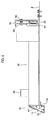
- Figs. 1 are an elevation view and a side sectional view of a medicine cart 1 according to the present invention
- Figs. 2 are an elevation view and a side sectional view of the medicine cart 1 of Fig. 1 with a shutter 2 thereof closed.
- the medicine cart 1 has a main body 3 formed in a box-like shape and having a front surface thereof open.
- the lower half part of the front surface of the main body 3 is oriented perpendicularly, and the upper half part thereof is inclined rearward.
- On the bottom surface of the main body 3, four casters 4 are provided so that the medicine cart 1 is movable.
- To the lower half part of the main body 3, three drawer bodies 5 are so provided vertically as to be drawable forward. In these drawer bodies 5, different types of supplies are stored.
- the opening in the front surface of the upper half part of the main body 3 is closable by the shutter 2 as shown in Fig. 2 .
- a drawing rack 6 is so provided as to be drawable forward.
- the aforementioned drawing rack 6 includes side plates 7 on the right and left sides and shelf plates 8 provided vertically in three steps. Each shelf plate 8 is so supported as to be drawable forward along a slide rail 9 provided on the side plate 7 on the right and left sides.
- the front ends of the shelf plates 8 provided vertically in three steps are arranged in a step-like manner so that the one in the first step is located more forward while those in the second and third steps are shifted more rearward at more upward position from the second to the third levels.
- a plurality of cassettes 10 are arranged respectively. To the front end of each shelf plate 8, as shown in Fig.
- a front panel 11 is so fitted as to be rotatable about a spindle 11a between the upright position (see the cassettes 10 in the first and third steps of Fig. 1(b) ) and the horizontal position (see the cassette 10 in the second step of Fig. 1(b) ).
- an LED12 is provided at a position facing the cassette 10.
- a catch 13 is provided, which engages with a catch receiver 14 provided to the side plate 7 when the shelf plate 8 is pressed in to thereby prevent the shelf plate 8 from improperly dropping out due to shock or the like.
- the respective cassettes 10 of the shelf plates 8 store different types of medicines (ampoules in this embodiment) 15 and thus have different sizes depending on the medicines 15 to be stored, though their basic structure are the same. Hereinafter, a description is given, referring to any one of the cassettes 10.
- the cassette 10 has an anteroposteriorly long box shape with the upper side thereof opening and is capable of storing the medicines 15 arranged in a row.
- the rear portion of the cassette 10 is formed higher than the full portion thereof.
- On the front end surface of the cassette 10, as shown in Fig. 4 there is formed a projection 17 which engages with a hole 16 provided in the rear surface of the front panel 11.
- the pin 19 has, as shown in Fig. 6(b) , an oval cross section provided at a position biased from the fitting center of a base 21 thereof.
- the pin receiver 20 has, as shown in Fig. 6(a) , a U-shaped cross section provided at a position biased from the fitting center of a base 22 thereof.
- the pin 19 and the pin receiver 21 can be fitted in ten levels at a fitting angle of 36 degrees, and hence improper fitting can be prevented by fitting each cassette 10 at a different angle.
- the pin 19 and the pin receiver 20 can be provided not only in one pair, but also in two or more pairs.
- the top surface of the rear portion of the cassette 10 is covered by a transparent cover 25, on which the name and a photo of the medicine to be stored in this cassette 10 are displayed.
- a coming-out preventing member 26 is fitted which is formed in the shape of an inverted L and which covers the upper portion including from the medicine 15a at the forefront to the shoulder part (if there is no shoulder part, a head part may be applied) of the medicine 15b at the second position that are both stored in the cassette 10.
- a slide groove 27 On the inner bottom surface of the cassette 10, as shown in Fig. 7 , there are formed a slide groove 27 on which a band plate of a constant force spring 54 of Fig. 10 to be described below is disposed and with which a pressing member 47 slidably engages; and a spacer fitting groove 29 which is fitted with a spacer 28 for adjusting the inner width of the cassette 10 in accordance with the size of the medicine 15.
- a vibration-preventing rail 30 is formed with which a vibration-preventing boss 49 of the pressing member 47 engages. Below the vibration-preventing rail 30, a slide resistance unit 31 and a rack gear 46 are so fitted as to extend anteropoteriorly.
- the slide resistance unit 31 as shown in Figs. 8 and 9 , has an insulating substrate 32 which is formed in an elongated rectangular shape and on one end of which a positive side conductive pattern 33, a negative side conductive pattern 34, and a detection side conductive pattern 35 are disposed.
- the negative side conductive pattern 34 extends to the other end of the substrate 32.
- two elongated first and second slide resistance plates 37 and 38 are attached in parallel by a two-sided tape 36.
- the first slide resistance plate 37 has a resistive paste 40 exposed on a Mylar film 39 with silver pastes 41 and 42 further exposed on both ends thereof.
- the resistive paste 40 between the silver pastes 41 and 42 has a resistance of 10 ⁇ .
- the second slide resistance plate 38 has a resistive paste 43 exposed on the Mylar film 39 with a silver paste 44 exposed on the one end portion to the other end portion through one of side edge portions.
- the silver paste 41 at one end of the first slide resistance plate 37 is connected to the positive side conductive pattern 33 via a metal fitting 45, and the silver paste 42 at the other end thereof is connected to the negative side conductive pattern 34 via the metal fitting 45.
- the silver paste 44 of the second slide resistance plate 38 is connected to the detection side conductive pattern 35 via a metal fitting 45.
- the positive side conductive pattern 33 of this slide resistance unit 31 is connected, as shown in Fig. 12 , to a Vcc terminal of 5V having a constant-voltage power supply, the negative side conductive pattern 34 is grounded, and the detection side conductive pattern 35 is connected to a detection terminal of a controller 100.
- the medicine 15 stored and arranged in a row in the cassette 10 is pressed forward by the pressing member 47.
- the pressing member 47 is, as shown in Fig. 10 , formed in the shape of a rectangular plate, on the bottom surface of which an engaging projection 48 for engaging with the slide groove 27 of the aforementioned cassette 10 is formed and on the side surface of which the vibration-preventing boss 49 for engaging with the vibration-preventing rail 30 of the cassette 10 is formed.
- the upper corner at the front end of the pressing member 47 is cut diagonally, forming an inclined surface 50.
- an insert guide part 51 is formed which is made of a surface formed in the shape of a circular arc as viewed from the direction in which the medicine is inserted.
- the angle of the inclined surface 50 is set so that the medicine 15 makes contact with the insert guide part 51 without fail when inserted from the above.
- the circular arc-shaped surface of the insert guide part 51 has a radius of curvature larger than the radius of the medicine 15.
- the insert guide part 51 continues to the front end surface of the pressing member 47.
- On the bottom of the pressing member 47 a depression 52a is formed which stores a constant force spring 53.
- the constant force spring 53 includes a longbandplatewoundaround. When leading end thereof is pulled out, it is restored with a certain magnitude of force. Therefore, Conston (Registered trademark) or the like that is commercially available is used.
- the band plate of the constant force spring 53 is, as shown in Fig.
- a pinion gear 54 which engages with the rack gear 46 of the aforementioned cassette 10 and an oil damper 55 which is coupled with the pinion gear 54. Load is imposed on the pinion gear 54 during rotation under the action of the oil damper 55. This permits preventing occurrence of problems such as that the pressing member 47 suddenly moves to hit the stored medicine 15 under influence of a biasing force of the constant force spring 53.
- This brush 56 includes a plate-like base 57 formed of an electric conductor and sliding parts 58 and 59 of conductive and elastic bodies fitted to the base 57 in parallel to each other.
- This brush 56 is designed such that fitting the base 57 to the pressing member 47 as shown in Fig. 11 causes the leading end portions of the sliding parts 58 and 59 to slidably make pressure contact with the first and second slide resistance plates 37 and 38 of the slide resistance unit 31.
- the sliding parts 58 and 59 each have a notch 60 formed on the leading ends thereof so as to make contact evenly with the slide resistance plates 37 and 38 even when inclined to some degree.
- each cassette 10 is provided with a locking lever 61 serving as a locking means, and an unlocking lever 62 and an unlocking pin 63 serving as unlocking means.
- the locking lever 61 is fixed to a common spindle 64 extending horizontally below the cassette 10 between both side walls of the shelf plate 8 so as to be rotatable.
- a claw 66 facing the interior of the cassette 10 through a hole 65 provided in the bottom wall of the cassette 10, and, on the other end portion thereof extending in the pushing-in direction of the shelf plate 8, there is formed a columnar protrusion 67 parallel to the common spindle 64. Due to a torsion spring 68 shown in Fig. 14 , the claw 66 of the locking lever 61 protrudes into the cassette 10 through the hole 65, and is biased so as to be engaged with the lower surface of the pressing member 47.
- the unlocking lever 62 is mounted to both side walls of the shelf plate 8 so as to be rotatable around a spindle 69 protruding parallel to the common spindle 64.
- the unlocking lever 62 includes an engagement portion 70 extending vertically downwards from the spindle 69, and an operating portion 71 extending from the upper portion of the spindle 69 in the drawing-out direction and the pushing-in direction of the shelf plate 8, and when seen along the spindle 69, it exhibits a substantially T-shaped configuration.
- the upper surface of the operating portion 71 constitutes a concave surface that is in contact with the columnar protrusion 67 of the locking lever 61 provided below each of the cassettes 10 situated at both ends.
- the unlocking pin 63 protrudes from the rear side (pushing-in side) portion of each of both side plates 7 in a columnar form, and when the shelf plate 8 is pushed in, it can be engaged with the engagement portion 70 of the unlocking lever 62.
- the locking lever 61 it is not always necessary for the locking lever 61 to be supported by the common spindle 64, and it may also be provided separately.
- the unlocking lever 62 is provided for each locking lever 61
- the unlocking pin 63 is also provided for each locking lever 61.
- the unlocking pin 63 is not restricted to a columnar one, and it may also be a plate-like one or a substitute such as a screw.
- the front panel 11 is opened to take out the cassette 10 from the shelf plate 8, the pressing member 47 is moved rearward, and a given number of medicines 15 are stored between the pressing member 47 and the front end of the cassette 10. The medicines 15 are pressed forward by the pressing member 47.
- the cassette side connector 24 and the shelf side connector 23 electrically contact with each other, whereby a voltage is supplied from the shelf plate 8 side to the slide resistance unit 31 of the cassette 10.
- the brush 56 of the pressing member 47 slides on the first and second slide resistance plates 37 and 38, and stops at a position in accordance with the quantity of the medicines 15.
- the controller 100 reads out voltage or processing conditions stored in a storage device, and a processor calculates the quantity of medicines corresponding to the detected voltage and outputs the results as the current quantity of medicines.
- the LED12 of the front panel 11 Based on prescription information transmitted from a host computer when the medicine cart 1 is connected to the host computer, or based on prescription information inputted with a bar code reader or a keyboard when the medicine cart 1 is stand alone, the LED12 of the front panel 11, which corresponds to the cassette 10 storing the medicines 15 required for prescription, lights up or blinks. Note that the LED12 also lights up or blinks when the medicines 15 are out of stock.
- the medicine 15 may be taken out by holding and lifting upward the medicine 15a at the forefront of the cassette 10.
- the medicine 15b at the second position may come out together with the medicine 15a at the forefront due to friction, but the medicine 15b at the second position hits the coming-out preventing member 26 to be thereby prevented from coming out.
- the row of the medicines 15 is pressed forward by the pressing member 47, and hence the medicine 15b located at the second position is placed at the forefront.
- the shelf plates 8 provided vertically in three steps are arranged in the step-like manner so that they are shifted more rearward at more upward position from the first, the second, to the third steps.
- the aforementioned medicine cart 1 is capable of reliably taking out the medicines 15 one by one and also capable of easily returning the medicine 15a once taken out to the cassette 10, thereby providing the excellent workability at the time of filling and returning the medicine 15.
- each cassette 10 is extracted from the shelf plate 8 to accommodate the medicines 15, it is also possible to accommodate the medicines 15 in each cassette 10 in a collective manner by drawing out the shelf plate 8 from the main body 3.
- the unlocking lever 62 When, in this state, the shelf plate 8 is drawn out from the main body 3 for the purpose of replenishment or inspection of the medicines 15, the unlocking lever 62 is, as shown in Fig. 17(b) , separated from the unlocking pin 63, and is freed from constraint.
- the locking lever 61 rotates counterclockwise due to the biasing force thereof, and the protrusion 67 thereof pushes down the operating portion 71 of the unlocking lever 62.
- the unlocking lever 62 rotates counterclockwise, and comes to a stop at the point in time when the protrusion 67 of the locking lever 61 comes to the center of the upper surface of the operating portion 71.
- the claw 66 of the locking lever 61 enters the hole 65 of the cassette 10. However, since the pressing member 47 has already moved forwards, the claw 66 is not engaged with the pressing member 47.
- the pressing member 47 of the cassette 10 in which the medicines 15 are to be accommodated is moved rearwards.
- the pressing member 47 goes over the claw 66 of the locking lever 61 while pressing down the same, the claw 66 of the locking lever 61 is engaged with the pressing member 47 and locked as shown in Fig. 17(c) .
- the pressing member 47 is locked at a predetermined rear position, and hence it is possible to replenish the space between the rearmost medicine 15 and the pressing member 47 with medicines 15 easily and quickly without having to press the pressing member 47 against the biasing force as in the prior art, thus facilitating the replenishing operation.
- first and second unlocking pins 63A, 63B are provided at two positions of the front side (drawing-out side) portion and the rear side (pushing-in side) portion of the side plate 7 of the main body 3, respectively.
- the first unlocking pin 63A on the front side is filled in with black.
- the unlocking member of the present invention is not restricted to this construction, and it may also be formed by a single component formed of a thin and elongated bar. That is, as shown in Fig. 19 , it may also be a flat unlocking bar 63C having a first unlocking end situated at the front side (drawing-out side) portion of the side plate 7 of the main body 3 and a second unlocking end situated at the rear side (pushing-in side) thereof.
- the unlocking lever 62 is in contact with the unlocking bar 63C, the lock of the pressing member 47 is canceled, and a similar effect is obtained.
- the shutter 2 can be closed so that an unauthorized third party cannot take out the medicine 15, which provides safety. Moreover, it is desirable for the medicine cart 1 to be powered off by closing the shutter 2.
- a display panel 3a is provided on the top surface of the main body of the medicine cart 1 and in which an image of the taken-out medicines 15 and the name and number thereof are displayed on the displaypanel 3a, whereby it is possible to check the taken-out medicines against the display on the display panel.
- an auxiliary shelf 3b on a side surface of the main body of the medicine cart 1 so as to be accommodated in the main body, and to use the auxiliary shelf as an operation stand on which the medicines 15 to be accommodated or the taken-out medicines 15 are temporarily placed.
Abstract
Description
- The present invention relates to a medicine cart having a large number of cassettes each of which stores a plurality of medicines arranged in an upright state in a row and which are respectively provided for different types of medicines, and allowing taking out or returning of medicines required at a hospital or the like one by one starting from the foremost one and also allowing calculation of the quantity of medicines taken out and stock control thereof.
- As an example of this type of medicine cart,
Patent Documents -
Patent Document 3 proposes a device in which a plurality of ampoules are accommodated in a row in a shelf portion, in which the rearmost ampoule is followed by a linear movement member, and in which the linear motion of the linear movement member is converted to a rotary motion, with the number of accommodated ampoules being counted based on the rotational displacement thereof. - Further,
Patent Document 4 also proposes a device in which, as inPatent Documents 1 through 3, ampoules are placed in a row in a medicine placing portion and biased forwardly by a pressing member. - Patent Document 1:
JP 2001-198194 A - Patent Document 2:
JP 2001-258994 A - Patent Document 3:
JP 2005-280971 A - Patent Document 4:
JP 2005-330048 A - However, in the devices of
Patent Documents Patent Document 4, the surface of the pressing member facing the medicine is formed so as to be curved and away from the ampoules as it extends upwardly, whereby the ampoule inserting operation is smoothed; however, the difficulty of charging the ampoules one by one while pressing the biasing member against the biasing force is not eliminated. - The present invention has been made in view of the aforementioned problem. It is accordingly an object of the present invention to provide a medicine cart which is free from the difficulty in filling it with medicines and which is of excellent workability.
- In order to solve the aforementionedproblem, the present invention provides a medicine cart including: a cassette which is upwardly open and accommodating a plurality of medicines in an upright state in a row; a shelf plate on which a plurality of the cassettes are placed and which can be drawn out of a main body of the medicine cart; and a pressing member provided in the cassette and adapted to forwardly press a rearmost medicine, in which a locking means for locking the pressing member at a predetermined position in the cassette, and an unlocking means for canceling the lock of the pressing member by the locking means through pushing-in operation and drawing-out operation of the shelf plate are provided.
- In the above solving means, when the shelf plate is drawn out, the pressing member can be locked at a predetermined position by the locking means. Since the unlocking means cancels the lock of the pressing member conducted by the locking means through pushing-in motion of the shelf member, there is no need to perform any special lock canceling after the completion of the medicine charging operation.
- It is desirable for the lockingmeans to include a locking lever rotatably provided on the cassette, and for the locking lever to be provided with a claw to be locked to the pressing member, with the claw being biased in a direction to be locked to the pressing member.
- It is desirable for the locking lever of each cassette to be fixed to a common spindle and rotatable around the common spindle. This helps to eliminate the need for provision of a spindle for each cassette, and further, since it is only necessary to rotate a single locking lever, it is possible to realize a simple construction.
- It is desirable for the unlocking means to include an unlocking lever which is rotatably provided on the shelf plate and adapted to rotate the locking lever against a biasing force to cancel the engagement of the claw of the locking lever and the pressing member, and an unlocking member which is provided on the main body of the medicine cart and adapted to be locked to the unlocking lever of at least one cassette at the time of pushing-in and drawing-out of the shelf plate.
- It is desirable for the unlocking lever to include an engagement portion to be engaged with the unlocking member and an operating portion abutting the locking lever to operate the locking lever.
- It is desirable for the engagement portion of the unlocking lever to extend downwards from the spindle of the unlocking lever, with the operating portion extending horizontally on both sides from the spindle of the locking lever. With this construction, whether the unlocking pin is engaged with the engagement portion from the pushing-in side or from the drawing-out side, the operating portion rotates, enabling the locking lever to operate.
- It is desirable for the unlocking member to include a first unlocking member provided on the front side portion of the main body and a second unlocking member provided on the rear side portion thereof. With this construction, when the shelf plate is pushed in, the unlocking lever immediately abuts the first unlocking member to cancel the lock, and hence the row of medicines in alignment are not disturbed or the rearmost medicine does not topple down.
- It is desirable for the unlocking member to include a pin. Instead, it may also be a plate-like projecting member, or a substitute such as a screw or the like.
- The unlocking member may be an unlocking bar having at both ends thereof a first unlocking end provided at a front side portion of the main body and a second unlocking end provided at a rear side portion of the main body.
- According to the present invention, there are provided a locking means and an unlocking means for the pressing member, and hence, by locking the pressing member at a predetermined position, there is no need to charge medicines while pressing the pressing member against the biasing force, making it possible to perform medicine charging operation easily and quickly. Further, it is also possible to charge a plurality of medicines at the same time. Since the locking means is unlocked with the pushing-in operation and the drawing-out operation of the shelf plate, there is no need to perform any special canceling operation after the completion of the medicine charging operation, whereby the difficulty in charging medicine is eliminated, and an improvement in terms of workability is achieved.
- Hereinafter, an embodiment of the present invention are described with reference to the accompanying drawings.
-
Figs. 1 are an elevation view and a side sectional view of amedicine cart 1 according to the present invention, andFigs. 2 are an elevation view and a side sectional view of themedicine cart 1 ofFig. 1 with ashutter 2 thereof closed. - The
medicine cart 1 has amain body 3 formed in a box-like shape and having a front surface thereof open. The lower half part of the front surface of themain body 3 is oriented perpendicularly, and the upper half part thereof is inclined rearward. On the bottom surface of themain body 3, fourcasters 4 are provided so that themedicine cart 1 is movable. To the lower half part of themain body 3, threedrawer bodies 5 are so provided vertically as to be drawable forward. In thesedrawer bodies 5, different types of supplies are stored. The opening in the front surface of the upper half part of themain body 3 is closable by theshutter 2 as shown inFig. 2 . To the upper half part of thismain body 3, adrawing rack 6 is so provided as to be drawable forward. - The
aforementioned drawing rack 6 includesside plates 7 on the right and left sides andshelf plates 8 provided vertically in three steps. Eachshelf plate 8 is so supported as to be drawable forward along aslide rail 9 provided on theside plate 7 on the right and left sides. The front ends of theshelf plates 8 provided vertically in three steps are arranged in a step-like manner so that the one in the first step is located more forward while those in the second and third steps are shifted more rearward at more upward position from the second to the third levels. On the top surfaces of theshelf plates 8, a plurality ofcassettes 10 are arranged respectively. To the front end of eachshelf plate 8, as shown inFig. 4 , afront panel 11 is so fitted as to be rotatable about aspindle 11a between the upright position (see thecassettes 10 in the first and third steps ofFig. 1(b) ) and the horizontal position (see thecassette 10 in the second step ofFig. 1(b) ). To thefront panel 11, an LED12 is provided at a position facing thecassette 10. To the rear end of eachshelf plate 8, acatch 13 is provided, which engages with a catch receiver 14 provided to theside plate 7 when theshelf plate 8 is pressed in to thereby prevent theshelf plate 8 from improperly dropping out due to shock or the like. - The
respective cassettes 10 of theshelf plates 8 store different types of medicines (ampoules in this embodiment) 15 and thus have different sizes depending on themedicines 15 to be stored, though their basic structure are the same. Hereinafter, a description is given, referring to any one of thecassettes 10. - As shown in
Fig. 3 , thecassette 10 has an anteroposteriorly long box shape with the upper side thereof opening and is capable of storing themedicines 15 arranged in a row. The rear portion of thecassette 10 is formed higher than the full portion thereof. On the front end surface of thecassette 10, as shown inFig. 4 , there is formed aprojection 17 which engages with ahole 16 provided in the rear surface of thefront panel 11. On the rear end surface of thecassette 10, there is provided apin receiver 20 which engages with apin 19 of a cassette fitting stay 18 vertically provided to theshelf plate 8. Thepin 19 has, as shown inFig. 6(b) , an oval cross section provided at a position biased from the fitting center of abase 21 thereof. Thepin receiver 20 has, as shown inFig. 6(a) , a U-shaped cross section provided at a position biased from the fitting center of abase 22 thereof. Thepin 19 and thepin receiver 21 can be fitted in ten levels at a fitting angle of 36 degrees, and hence improper fitting can be prevented by fitting eachcassette 10 at a different angle. Thepin 19 and thepin receiver 20 can be provided not only in one pair, but also in two or more pairs. On the rear end of thecassette 10 below thepin receiver 20, there is provided acassette side connector 24 which is electrically connected to ashelf side connector 23 provided to the cassette fitting stay 18. The top surface of the rear portion of thecassette 10 is covered by atransparent cover 25, on which the name and a photo of the medicine to be stored in thiscassette 10 are displayed. To the side surface of the front portion of thecassette 10, a coming-out preventing member 26 is fitted which is formed in the shape of an inverted L and which covers the upper portion including from themedicine 15a at the forefront to the shoulder part (if there is no shoulder part, a head part may be applied) of themedicine 15b at the second position that are both stored in thecassette 10. - On the inner bottom surface of the
cassette 10, as shown inFig. 7 , there are formed aslide groove 27 on which a band plate of aconstant force spring 54 ofFig. 10 to be described below is disposed and with which apressing member 47 slidably engages; and aspacer fitting groove 29 which is fitted with aspacer 28 for adjusting the inner width of thecassette 10 in accordance with the size of themedicine 15. On the inner side surface of thecassette 10, a vibration-preventingrail 30 is formed with which a vibration-preventingboss 49 of the pressingmember 47 engages. Below the vibration-preventingrail 30, aslide resistance unit 31 and arack gear 46 are so fitted as to extend anteropoteriorly. - The
slide resistance unit 31, as shown inFigs. 8 and9 , has an insulatingsubstrate 32 which is formed in an elongated rectangular shape and on one end of which a positive sideconductive pattern 33, a negative sideconductive pattern 34, and a detection sideconductive pattern 35 are disposed. The negative sideconductive pattern 34 extends to the other end of thesubstrate 32. On theconductive patterns substrate 32, two elongated first and secondslide resistance plates sided tape 36. The firstslide resistance plate 37 has aresistive paste 40 exposed on aMylar film 39 with silver pastes 41 and 42 further exposed on both ends thereof. Theresistive paste 40 between the silver pastes 41 and 42 has a resistance of 10Ω. Similarly, the secondslide resistance plate 38 has aresistive paste 43 exposed on theMylar film 39 with asilver paste 44 exposed on the one end portion to the other end portion through one of side edge portions. Thesilver paste 41 at one end of the firstslide resistance plate 37 is connected to the positive sideconductive pattern 33 via ametal fitting 45, and thesilver paste 42 at the other end thereof is connected to the negative sideconductive pattern 34 via themetal fitting 45. Thesilver paste 44 of the secondslide resistance plate 38 is connected to the detection sideconductive pattern 35 via ametal fitting 45. The positive sideconductive pattern 33 of thisslide resistance unit 31 is connected, as shown inFig. 12 , to a Vcc terminal of 5V having a constant-voltage power supply, the negative sideconductive pattern 34 is grounded, and the detection sideconductive pattern 35 is connected to a detection terminal of acontroller 100. - The
medicine 15 stored and arranged in a row in thecassette 10 is pressed forward by the pressingmember 47. The pressingmember 47 is, as shown inFig. 10 , formed in the shape of a rectangular plate, on the bottom surface of which an engagingprojection 48 for engaging with theslide groove 27 of theaforementioned cassette 10 is formed and on the side surface of which the vibration-preventingboss 49 for engaging with the vibration-preventingrail 30 of thecassette 10 is formed. The upper corner at the front end of the pressingmember 47 is cut diagonally, forming aninclined surface 50. On thisinclined surface 50, aninsert guide part 51 is formed which is made of a surface formed in the shape of a circular arc as viewed from the direction in which the medicine is inserted. The angle of theinclined surface 50 is set so that themedicine 15 makes contact with theinsert guide part 51 without fail when inserted from the above. The circular arc-shaped surface of theinsert guide part 51 has a radius of curvature larger than the radius of themedicine 15. The insert guidepart 51 continues to the front end surface of the pressingmember 47. On the bottom of the pressingmember 47, adepression 52a is formed which stores aconstant force spring 53. Theconstant force spring 53 includes a longbandplatewoundaround. When leading end thereof is pulled out, it is restored with a certain magnitude of force. Therefore, Conston (Registered trademark) or the like that is commercially available is used. The band plate of theconstant force spring 53 is, as shown inFig. 11 , disposed along theslide groove 27 of thecassette 10, with the leading end thereof fixed to the front end ofcassette 10. To aprojection 47a formed in the shape of an L and provided on the rear end surface of the pressingmember 47, there are provided apinion gear 54 which engages with therack gear 46 of theaforementioned cassette 10 and anoil damper 55 which is coupled with thepinion gear 54. Load is imposed on thepinion gear 54 during rotation under the action of theoil damper 55. This permits preventing occurrence of problems such as that the pressingmember 47 suddenly moves to hit the storedmedicine 15 under influence of a biasing force of theconstant force spring 53. - Below the vibration-preventing
boss 49 on the side surface of the pressingmember 47, adepression 52b is formed, to which a pair ofbrushes 56 are fitted which makes sliding contact with the aforementionedslide resistance unit 31. Thisbrush 56 includes a plate-like base 57 formed of an electric conductor and slidingparts brush 56 is designed such that fitting the base 57 to the pressingmember 47 as shown inFig. 11 causes the leading end portions of the slidingparts slide resistance plates slide resistance unit 31. The slidingparts notch 60 formed on the leading ends thereof so as to make contact evenly with theslide resistance plates - As shown in
Figs. 13 ,14 , and15 , eachcassette 10 is provided with a lockinglever 61 serving as a locking means, and an unlockinglever 62 and an unlockingpin 63 serving as unlocking means. - As shown in
Fig. 16 , the lockinglever 61 is fixed to acommon spindle 64 extending horizontally below thecassette 10 between both side walls of theshelf plate 8 so as to be rotatable. As shown inFig. 15 , on the upper surface of one end portion of the lockinglever 61 extending in the pushing-in direction of theshelf plate 8, there is formed aclaw 66 facing the interior of thecassette 10 through ahole 65 provided in the bottom wall of thecassette 10, and, on the other end portion thereof extending in the pushing-in direction of theshelf plate 8, there is formed acolumnar protrusion 67 parallel to thecommon spindle 64. Due to atorsion spring 68 shown inFig. 14 , theclaw 66 of the lockinglever 61 protrudes into thecassette 10 through thehole 65, and is biased so as to be engaged with the lower surface of the pressingmember 47. - The unlocking
lever 62 is mounted to both side walls of theshelf plate 8 so as to be rotatable around aspindle 69 protruding parallel to thecommon spindle 64. The unlockinglever 62 includes anengagement portion 70 extending vertically downwards from thespindle 69, and an operatingportion 71 extending from the upper portion of thespindle 69 in the drawing-out direction and the pushing-in direction of theshelf plate 8, and when seen along thespindle 69, it exhibits a substantially T-shaped configuration. The upper surface of the operatingportion 71 constitutes a concave surface that is in contact with thecolumnar protrusion 67 of the lockinglever 61 provided below each of thecassettes 10 situated at both ends. - The unlocking
pin 63 protrudes from the rear side (pushing-in side) portion of each of bothside plates 7 in a columnar form, and when theshelf plate 8 is pushed in, it can be engaged with theengagement portion 70 of the unlockinglever 62. - It is not always necessary for the locking
lever 61 to be supported by thecommon spindle 64, and it may also be provided separately. In this case, the unlockinglever 62 is provided for each lockinglever 61, and the unlockingpin 63 is also provided for each lockinglever 61. The unlockingpin 63 is not restricted to a columnar one, and it may also be a plate-like one or a substitute such as a screw. - In the
medicine cart 1 structured as described above, to store themedicine 15, thefront panel 11 is opened to take out thecassette 10 from theshelf plate 8, the pressingmember 47 is moved rearward, and a given number ofmedicines 15 are stored between the pressingmember 47 and the front end of thecassette 10. Themedicines 15 are pressed forward by the pressingmember 47. - When the
cassette 10 is fitted to theshelf plate 8, thecassette side connector 24 and theshelf side connector 23 electrically contact with each other, whereby a voltage is supplied from theshelf plate 8 side to theslide resistance unit 31 of thecassette 10. Thebrush 56 of the pressingmember 47 slides on the first and secondslide resistance plates medicines 15. Where the stop position of thebrush 56 is P, as shown inFig. 12 , a partial pressure ofVp=R2/R is inputted to thecontroller 100 via thebrush 56 located at the P position. Thecontroller 100 reads out voltage or processing conditions stored in a storage device, and a processor calculates the quantity of medicines corresponding to the detected voltage and outputs the results as the current quantity of medicines. - Based on prescription information transmitted from a host computer when the
medicine cart 1 is connected to the host computer, or based on prescription information inputted with a bar code reader or a keyboard when themedicine cart 1 is stand alone, the LED12 of thefront panel 11, which corresponds to thecassette 10 storing themedicines 15 required for prescription, lights up or blinks. Note that the LED12 also lights up or blinks when themedicines 15 are out of stock. - The
medicine 15 may be taken out by holding and lifting upward themedicine 15a at the forefront of thecassette 10. In this operation, themedicine 15b at the second position may come out together with themedicine 15a at the forefront due to friction, but themedicine 15b at the second position hits the coming-out preventingmember 26 to be thereby prevented from coming out. When themedicine 15a at the forefront is taken out, the row of themedicines 15 is pressed forward by the pressingmember 47, and hence themedicine 15b located at the second position is placed at the forefront. In this manner, the required quantity ofmedicines 15 can be taken out sequentially. Theshelf plates 8 provided vertically in three steps are arranged in the step-like manner so that they are shifted more rearward at more upward position from the first, the second, to the third steps. Thus, when themedicine 15 is to be taken out from thecassette 10 of theshelf plate 8 located at the first step at the bottom, theshelf plate 8 at the second step does not get in the way. - When a
wrong medicine 15a is taken out or when anextra medicine 15a is taken out, thismedicine 15a needs to be returned to thecassette 10. In this case, as shown inFig. 3 , by pressing the bottom of themedicine 15 along theinsert guide part 51 of the pressingmember 47, themedicine 15 is inserted between themedicine 15c at the rearmost and the pressingmember 47 to be thereby located at the rearmost. - In this manner, the
aforementioned medicine cart 1 is capable of reliably taking out themedicines 15 one by one and also capable of easily returning themedicine 15a once taken out to thecassette 10, thereby providing the excellent workability at the time of filling and returning themedicine 15. - While in the aforementioned case each
cassette 10 is extracted from theshelf plate 8 to accommodate themedicines 15, it is also possible to accommodate themedicines 15 in eachcassette 10 in a collective manner by drawing out theshelf plate 8 from themain body 3. - That is, as shown in
Fig. 17(a) , in the state in which theshelf plate 8 has been inserted into themain body 3, theengagement portion 70 of the unlockinglever 62 abuts the unlockingpin 63 and rotates clockwise, with the end portion of the operatingportion 71 pushing up theprotrusion 67 of the lockinglever 61. As a result, the lockinglever 61 rotates clockwise against the biasing force, and theclaw 66 is retracted from thehole 65 of thecassette 10. As a result, the pressingmember 47 moves forwards, and presses therearmost medicine 15 forwardly. - When, in this state, the
shelf plate 8 is drawn out from themain body 3 for the purpose of replenishment or inspection of themedicines 15, the unlockinglever 62 is, as shown inFig. 17(b) , separated from the unlockingpin 63, and is freed from constraint. As a result, the lockinglever 61 rotates counterclockwise due to the biasing force thereof, and theprotrusion 67 thereof pushes down the operatingportion 71 of the unlockinglever 62. As a result, the unlockinglever 62 rotates counterclockwise, and comes to a stop at the point in time when theprotrusion 67 of the lockinglever 61 comes to the center of the upper surface of the operatingportion 71. Theclaw 66 of the lockinglever 61 enters thehole 65 of thecassette 10. However, since the pressingmember 47 has already moved forwards, theclaw 66 is not engaged with the pressingmember 47. - Next, of the
cassettes 10 of the drawn-outshelf plate 8, the pressingmember 47 of thecassette 10 in which themedicines 15 are to be accommodated is moved rearwards. When the pressingmember 47 goes over theclaw 66 of the lockinglever 61 while pressing down the same, theclaw 66 of the lockinglever 61 is engaged with the pressingmember 47 and locked as shown inFig. 17(c) . - In this way, the pressing
member 47 is locked at a predetermined rear position, and hence it is possible to replenish the space between therearmost medicine 15 and the pressingmember 47 withmedicines 15 easily and quickly without having to press the pressingmember 47 against the biasing force as in the prior art, thus facilitating the replenishing operation. - When, as shown in
Fig. 17(d) , theshelf plate 8 with thecassette 10 replenished with themedicines 15 indicated by the hatched portion in the drawing is pushed into themain body 3, theengagement portion 70 of the unlockinglever 62 abuts the unlockingpin 63 and rotates clockwise, and the end portion of the operatingportion 71 pushes up theprotrusion 67 of the lockinglever 61. As a result, the lockinglever 61 rotates clockwise against the biasing force thereof, and theclaw 66 retreats from the pressingmember 47. As a result, the pressingmember 47 presses therearmost medicine 15, and normal taking-out operation of themedicine 15 becomes possible as shown inFig. 17(a) . - In
Figs. 18(a) through 18(d) , first and second unlockingpins side plate 7 of themain body 3, respectively. In order to clearly distinguish the two unlocking pins from each other, the first unlockingpin 63A on the front side is filled in with black. - When the
shelf plate 8 in the accommodated state shown inFig. 18(a) is drawn out, the unlockinglever 62 goes over the first unlockingpin 63A on the front side and the state as shown inFig. 18 (b) is attained. Here, as shown inFig. 18(c) , the pressingmember 47 is moved rearwards to be locked. When, in this locked state, nomedicine 15 is accommodated or filling with themedicines 15 is not effected, pushing theshelf plate 8 into themain body 3 causes the unlockinglever 62 to abut the first unlockingpin 63 on the front side and rotate, and hence the lockinglever 61 rotates, and the lock of the pressingmember 47 is canceled. As a result, the pressingmember 47 moves forwards, and presses therearmost medicine 15. In this way, by providing the unlockingpins side plate 7 of themain body 3, it is possible to cancel the lock of the pressingmember 47 immediately after the pushing-in of theshelf plate 8, and it is possible to prevent disturbance of the row ofmedicines 15 and toppling down of therearmost medicine 15 due to vibration involved at the time of pushing-in operation. - While the first unlocking pin A and the second unlocking
pin 63B are separate members, the unlocking member of the present invention is not restricted to this construction, and it may also be formed by a single component formed of a thin and elongated bar. That is, as shown inFig. 19 , it may also be a flat unlockingbar 63C having a first unlocking end situated at the front side (drawing-out side) portion of theside plate 7 of themain body 3 and a second unlocking end situated at the rear side (pushing-in side) thereof. In this case, while the unlockinglever 62 is in contact with the unlockingbar 63C, the lock of the pressingmember 47 is canceled, and a similar effect is obtained. - When the
medicine cart 1 is not in use, theshutter 2 can be closed so that an unauthorized third party cannot take out themedicine 15, which provides safety. Moreover, it is desirable for themedicine cart 1 to be powered off by closing theshutter 2. - In the aforementioned embodiment, it is possible to adopt a construction in which, as shown in
Fig. 20 , adisplay panel 3a is provided on the top surface of the main body of themedicine cart 1 and in which an image of the taken-outmedicines 15 and the name and number thereof are displayed on thedisplaypanel 3a, whereby it is possible to check the taken-out medicines against the display on the display panel. Further, it is also possible to provide anauxiliary shelf 3b on a side surface of the main body of themedicine cart 1 so as to be accommodated in the main body, and to use the auxiliary shelf as an operation stand on which themedicines 15 to be accommodated or the taken-outmedicines 15 are temporarily placed. -
- [
Figs. 1 ] Part (a) is an elevation view of a medicine cart according to the present invention, and part (b) is a side sectional view thereof. - [
Figs. 2 ] Part (a) is an elevation view of the medicine cart ofFig. 1 with a shutter closed, and part (b) is a side sectional view thereof. - [
Fig. 3 ] A perspective view of a cassette. - [
Fig. 4 ] A side view of the cassette. - [
Fig. 5 ] A diagram of the cassette as viewed from the above. - [
Fig. 6 ] An elevation views of a pin and a pin receiver of the cassette. - [
Fig. 7 ] A sectional view of the cassette. - [
Fig. 8 ] A plan view of a slide resistance unit. - [
Fig. 9 ] An exploded perspective view of the slide resistance unit ofFig. 8 . - [
Figs. 10 ] Part (a) is a sectional view of a pressing member, part (b) is a back view thereof, and part (c) is a plan view thereof. - [
Fig. 11 ] A longitudinal sectional view of the cassette. - [
Fig. 12 ] A circuit diagram of a measuring device using the slide resistance unit. - [
Fig. 13 ] An enlarged side view of a pressing member provided with a locking means and an unlocking means. - [
Fig. 14 ] A sectional view ofFig. 13 . - [
Fig. 15 ] A perspective view of the locking means and the unlocking means ofFig. 13 . - [
Fig. 16 ] A perspective view of a shelf plate, showing the positional relationship between the locking lever, a common spindle, an unlocking lever, and an unlocking pin ofFig. 13 . - [
Fig. 17 ] A side view sequentially showing an example of the operations of the locking means and the unlocking means. - [
Fig. 18 ] A side view sequentially showing another example of the operations of the locking means and the unlocking means. - [
Fig. 19 ] A side view showing another example of the unlocking means. - [
Fig. 20 ] A perspective view of the medicine cart. - 1 medicine cart, 8 shelf plate, 10 cassette, 15 medicines, 47 pressing member, 61 locking lever (locking means), 62 unlocking lever (locking means), 63 unlocking pin (locking means), 63A first unlocking pin (locking means), 63B second unlocking pins (locking means), 63C unlocking bar (locking means), 66 claw, 68 torsion spring
Claims (9)
- A medicine cart comprising: a cassette which is upwardly open and accommodating a plurality of medicines in an upright state in a row; a shelf plate on which a plurality of the cassettes are placed and which can be drawn out of a main body of the medicine cart; and a pressing member provided in the cassette and adapted to forwardly press a rearmost medicine, wherein a locking means for locking the pressing member at a predetermined position in the cassette, and an unlocking means for canceling the lock of the pressing member by the locking means through pushing-in operation and drawing-out operation of the shelf plate are provided.
- A medicine cart according to Claim 1, wherein the locking means comprises a locking lever rotatably provided on the cassette, and wherein the locking lever is provided with a claw to be locked to the pressing member, with the claw being biased in a direction to be locked to the pressing member.
- A medicine cart according to Claim 2, wherein the locking lever of each cassette is fixed to a common spindle and rotatable around the common spindle.
- A medicine cart according to Claim 2 or 3, wherein the unlocking means comprises an unlocking lever which is rotatably provided on the shelf plate and adapted to rotate the locking lever against a biasing force to cancel the engagement of the claw of the locking lever and the pressing member, and an unlocking member which is provided on the main body of the medicine cart and adapted to be locked to the unlocking lever of at least one cassette at the time of pushing-in and drawing-out of the shelf plate.
- A medicine cart according to Claim 4, wherein the unlocking lever comprises an engagement portion to be engaged with the unlocking member and an operating portion abutting the locking lever to operate the locking lever.
- A medicine cart according to Claim 5, wherein the engagement portion of the unlocking lever extends downwardly from the spindle of the unlocking lever, and wherein the operating portion extends horizontally on both sides from the spindle of the locking lever.
- A medicine cart according to any one of Claims 4 through 6, wherein the unlocking member comprises a first unlocking member provided at a front side portion of the main body and a second unlocking member provided at a rear side portion of the main body.
- A medicine cart according to any one of Claims 4 through 7, wherein the unlocking member comprises a pin.
- A medicine cart according to any one of Claims 4 through 6, wherein the unlocking member comprises an unlocking bar having at both ends thereof a first unlocking end provided at a front side portion of the main body and a second unlocking end provided at a rear side portion of the main body.
Applications Claiming Priority (2)
| Application Number | Priority Date | Filing Date | Title |
|---|---|---|---|
| JP2006085533A JP4961791B2 (en) | 2006-03-27 | 2006-03-27 | Drug cart |
| PCT/JP2007/055211 WO2007111142A1 (en) | 2006-03-27 | 2007-03-15 | Medicine cart |
Publications (3)
| Publication Number | Publication Date |
|---|---|
| EP2000424A2 true EP2000424A2 (en) | 2008-12-10 |
| EP2000424A9 EP2000424A9 (en) | 2009-03-18 |
| EP2000424A4 EP2000424A4 (en) | 2011-11-09 |
Family
ID=38541063
Family Applications (1)
| Application Number | Title | Priority Date | Filing Date |
|---|---|---|---|
| EP07738661A Withdrawn EP2000424A4 (en) | 2006-03-27 | 2007-03-15 | Medicine cart |
Country Status (6)
| Country | Link |
|---|---|
| US (1) | US8146753B2 (en) |
| EP (1) | EP2000424A4 (en) |
| JP (1) | JP4961791B2 (en) |
| KR (1) | KR101352656B1 (en) |
| CN (1) | CN101410311B (en) |
| WO (1) | WO2007111142A1 (en) |
Cited By (11)
| Publication number | Priority date | Publication date | Assignee | Title |
|---|---|---|---|---|
| US8403345B2 (en) | 2011-05-13 | 2013-03-26 | Michael Angelo Designs, Llc | Apparatus with wire cart for moving, storing and dispensing spooled material |
| CN103144881A (en) * | 2012-08-20 | 2013-06-12 | 苏州艾隆科技股份有限公司 | Drug delivery manipulator |
| CN103144879A (en) * | 2012-08-20 | 2013-06-12 | 苏州艾隆科技股份有限公司 | Drug delivery manipulator |
| CN103144878A (en) * | 2012-08-20 | 2013-06-12 | 苏州艾隆科技股份有限公司 | Drug delivery manipulator |
| CN103144880A (en) * | 2012-08-20 | 2013-06-12 | 苏州艾隆科技股份有限公司 | Drug delivery manipulator |
| CN103158970A (en) * | 2012-08-20 | 2013-06-19 | 苏州艾隆科技股份有限公司 | Dispensing manipulator |
| CN103158969A (en) * | 2012-08-20 | 2013-06-19 | 苏州艾隆科技股份有限公司 | Dispensing manipulator |
| US8616485B2 (en) | 2011-05-13 | 2013-12-31 | Michael Angelo Designs, Llc | Apparatus for moving and dispensing spooled material |
| US9150119B2 (en) | 2013-03-15 | 2015-10-06 | Aesynt Incorporated | Apparatuses, systems, and methods for anticipating and delivering medications from a central pharmacy to a patient using a track based transport system |
| EP2869734A4 (en) * | 2012-07-09 | 2016-03-23 | Checkpoint Systems Inc | Item pusher apparatus with channel-based shuttle displacement detection and associated methods |
| US9511945B2 (en) | 2012-10-12 | 2016-12-06 | Aesynt Incorporated | Apparatuses, systems, and methods for transporting medications from a central pharmacy to a patient in a healthcare facility |
Families Citing this family (23)
| Publication number | Priority date | Publication date | Assignee | Title |
|---|---|---|---|---|
| US8485391B2 (en) * | 2003-10-17 | 2013-07-16 | Rock-Tenn Shared Services, Llc | Theft deterrent system |
| US8190289B2 (en) | 2003-10-17 | 2012-05-29 | Rock-Tenn Shared Services, Llc | Dispensing and display system |
| US8353425B2 (en) * | 2005-04-25 | 2013-01-15 | Rock-Tenn Shared Services, Llc | Time delay product pushing system |
| US8251629B2 (en) * | 2007-02-09 | 2012-08-28 | Cerner Innovation, Inc. | Medication dispensing apparatus |
| JP5013972B2 (en) * | 2007-05-31 | 2012-08-29 | サンデン株式会社 | Vending machine product column |
| US8428774B2 (en) * | 2009-06-04 | 2013-04-23 | Checkpoint Systems, Inc. | Apparatus and method for single unit access display |
| US9119488B2 (en) | 2009-09-25 | 2015-09-01 | Rock-Tenn Shared Services, Llc | Secure merchandising display with blocker mechanisms |
| CN102596147B (en) * | 2009-10-21 | 2014-07-16 | 株式会社汤山制作所 | Medication dispensing device |
| US8646650B2 (en) | 2010-05-19 | 2014-02-11 | Rock-Tenn Shared Services, Llc | Product dispensing system |
| KR101254633B1 (en) * | 2011-03-15 | 2013-04-15 | (주)제이브이엠 | Drug dispenser and using this Drug dispensing method |
| KR101254651B1 (en) * | 2011-03-15 | 2013-04-15 | (주)제이브이엠 | Drug dispenser |
| US8910827B2 (en) | 2011-05-10 | 2014-12-16 | Rock-Tenn Shared Services, Llc | Secure merchandising display with tunnel feature |
| US8941495B2 (en) | 2011-06-10 | 2015-01-27 | Checkpoint Systems, Inc. | Wireless shelf pusher activity detection system and associated methods |
| CN102602639B (en) * | 2012-03-15 | 2014-04-16 | 江苏迅捷装具科技有限公司 | Device and method for storage and distribution based on arrangement of largest sides contact of boxed products |
| KR102019706B1 (en) * | 2012-11-01 | 2019-09-09 | (주)제이브이엠 | dispenser and catridge having the combination structure for mutual connection |
| CN103144901B (en) * | 2012-12-17 | 2015-08-12 | 苏州艾隆科技股份有限公司 | Injection distributor disk and there is its Injection solution distributor |
| CN103144902B (en) * | 2012-12-17 | 2015-08-12 | 苏州艾隆科技股份有限公司 | Injection solution distributor |
| US9474670B2 (en) * | 2014-12-18 | 2016-10-25 | Krz, S.L. | Cart for dispensing health products |
| EP3250086A2 (en) * | 2015-01-28 | 2017-12-06 | The Heartbeat Manufacturing Co (Redditch) Limited | Shelf management device |
| CN104960836B (en) * | 2015-06-24 | 2017-10-03 | 上海观谷科技有限公司 | Medicine storage tank |
| US20180213946A1 (en) * | 2015-07-13 | 2018-08-02 | Idesign Innovations Pty Ltd | An anti-theft storage and display assembly |
| WO2017184961A1 (en) * | 2016-04-22 | 2017-10-26 | Wal-Mart Stores, Inc. | Product count tracking device |
| CN106144378B (en) * | 2016-06-29 | 2018-09-14 | 苏州信亨自动化科技有限公司 | Bottled medicament automatic medicine-dispensing device |
Citations (3)
| Publication number | Priority date | Publication date | Assignee | Title |
|---|---|---|---|---|
| US5570811A (en) * | 1994-11-01 | 1996-11-05 | Fawn Engineering Corporation | Apparatus and method for dispensing items from a vending machine |
| WO2005110333A1 (en) * | 2004-05-19 | 2005-11-24 | Yuyama Mfg. Co., Ltd. | Medicine dispensing device |
| JP2005330048A (en) * | 2004-05-19 | 2005-12-02 | Takazono Sangyo Co Ltd | Cassette for storing drug and drug storing device |
Family Cites Families (42)
| Publication number | Priority date | Publication date | Assignee | Title |
|---|---|---|---|---|
| US4200201A (en) * | 1977-01-24 | 1980-04-29 | Rod Pierce and Associates | Machine having module with carriage for advancing row of articles |
| US4134520A (en) * | 1977-01-24 | 1979-01-16 | Rod Pierce & Associates | Article dispensing machine with spring-driven carriages for advancing articles to be dispensed |
| US4397606A (en) * | 1980-12-11 | 1983-08-09 | Bruton Rose L | Article handling apparatus and method for restocking store shelves |
| AU6032786A (en) * | 1985-07-25 | 1987-01-29 | University Of Minnesota | Detection, imaging and therapy of renal cell carcinoma with monoclonal antibodies in vivo |
| JPS6336494U (en) * | 1986-08-19 | 1988-03-09 | ||
| US4730741A (en) * | 1986-10-16 | 1988-03-15 | The Niven Marketing Group | Pressure-feed tray system |
| US4762236A (en) * | 1986-10-16 | 1988-08-09 | The Niven Marketing Group | Adjustable tray dispensing apparatus |
| US4771898A (en) * | 1987-02-17 | 1988-09-20 | Sara Lee Corporation | Display and pull-out tray assemblies for integrated modular store fixture system |
| US4836390A (en) * | 1987-10-15 | 1989-06-06 | Polvere Dennis J | Rack for dispensing articles |
| US4907707A (en) * | 1988-04-04 | 1990-03-13 | Oscar Mayer Foods Corporation | Merchandiser assembly |
| US5123546A (en) * | 1988-04-04 | 1992-06-23 | Oscar Mayer Foods Corporation | Merchandiser assembly |
| US5012936A (en) * | 1988-04-04 | 1991-05-07 | Oscar Meyer Foods Corporation | Merchandiser assembly |
| US5069511A (en) * | 1990-05-10 | 1991-12-03 | Herman Miller, Inc. | Pharmaceutical cabinet locking arrangement |
| US5263596A (en) * | 1991-12-02 | 1993-11-23 | Williams David R | Medication dispenser station sub-assembly |
| US5460294A (en) * | 1994-05-12 | 1995-10-24 | Pyxis Corporation | Single dose pharmaceutical dispenser subassembly |
| JPH09264290A (en) * | 1996-03-29 | 1997-10-07 | Sanyo Electric Co Ltd | Elevating device of electric fan |
| US7048142B1 (en) * | 1997-04-30 | 2006-05-23 | Automed Technologies, Inc. | Apparatus for dispensing medical items |
| US5881910A (en) * | 1997-08-17 | 1999-03-16 | Advertising Display Company | Numerical inventory control device |
| JP2000248837A (en) * | 1999-02-26 | 2000-09-12 | Nagano Kagaku Kikai Seisakusho:Kk | Keeping device with unlocking immobilization means and control system for the same |
| US6659293B1 (en) * | 1999-07-07 | 2003-12-09 | Odwalla, Inc. | Pull-out shelf stocking system |
| JP4582846B2 (en) | 2000-01-18 | 2010-11-17 | 株式会社トーショー | Chemical storage device |
| JP4462689B2 (en) * | 2000-01-18 | 2010-05-12 | 株式会社トーショー | Chemical storage device |
| JP4601116B2 (en) * | 2000-03-17 | 2010-12-22 | 株式会社トーショー | Chemical storage device |
| US6375015B1 (en) * | 2000-07-27 | 2002-04-23 | Chicago Show | Shelving system and display unit therefor |
| EP1489000B1 (en) * | 2002-02-20 | 2009-08-12 | Sanyo Electric Co., Ltd. | Medicine supply apparatus |
| JP2003250674A (en) * | 2002-02-28 | 2003-09-09 | Sanden Corp | Shelf device of show case |
| US20030222548A1 (en) * | 2002-05-31 | 2003-12-04 | Richardson William R. | Storage device for health care facility |
| US20030201697A1 (en) * | 2002-04-30 | 2003-10-30 | Richardson William R. | Storage device for health care facility |
| TWI290898B (en) * | 2002-08-05 | 2007-12-11 | Yuyama Mfg Co Ltd | Feeding device of drug |
| TWI295573B (en) * | 2002-10-18 | 2008-04-11 | Yuyama Mfg Co Ltd | Feeding device of drug |
| JP2004258242A (en) * | 2003-02-25 | 2004-09-16 | Olympus Corp | Image display device and program |
| US6964344B1 (en) * | 2003-09-26 | 2005-11-15 | Kim Chang S | Display tray and rack assembly |
| JP2005280971A (en) * | 2004-03-31 | 2005-10-13 | Kumahira Safe Co Inc | Storage rack device |
| CA2562865C (en) * | 2004-05-07 | 2011-08-30 | Sca Hygiene Products Ab | Apparatus for serially dispensing folded sheet products |
| CN1976670B (en) * | 2004-05-19 | 2011-10-26 | 株式会社汤山制作所 | Medicine dispensing device |
| KR100635336B1 (en) * | 2004-08-13 | 2006-10-18 | 표성호 | Beverage Display Drawer |
| JP4520814B2 (en) * | 2004-10-15 | 2010-08-11 | 株式会社湯山製作所 | Chemical dispensing device |
| JP5119593B2 (en) * | 2005-01-13 | 2013-01-16 | 株式会社湯山製作所 | Article dispensing apparatus, method, and medicine dispensing apparatus |
| US20060186065A1 (en) * | 2005-02-19 | 2006-08-24 | Ciesick James M | Telescoping display rack |
| US8038017B2 (en) * | 2006-01-13 | 2011-10-18 | Close in Solutions, LLC | Spring driven method and apparatus for in-carton display and fronting of merchandise items |
| US7690519B2 (en) * | 2008-03-10 | 2010-04-06 | Display Specialties, Inc. | Extendable product shelving |
| US7876993B2 (en) * | 2008-05-05 | 2011-01-25 | Adc Telecommunications, Inc. | Drawer arrangement with rack and pinion |
-
2006
- 2006-03-27 JP JP2006085533A patent/JP4961791B2/en not_active Expired - Fee Related
-
2007
- 2007-03-15 CN CN2007800113385A patent/CN101410311B/en not_active Expired - Fee Related
- 2007-03-15 WO PCT/JP2007/055211 patent/WO2007111142A1/en active Application Filing
- 2007-03-15 KR KR1020087023568A patent/KR101352656B1/en active IP Right Grant
- 2007-03-15 US US12/293,800 patent/US8146753B2/en not_active Expired - Fee Related
- 2007-03-15 EP EP07738661A patent/EP2000424A4/en not_active Withdrawn
Patent Citations (3)
| Publication number | Priority date | Publication date | Assignee | Title |
|---|---|---|---|---|
| US5570811A (en) * | 1994-11-01 | 1996-11-05 | Fawn Engineering Corporation | Apparatus and method for dispensing items from a vending machine |
| WO2005110333A1 (en) * | 2004-05-19 | 2005-11-24 | Yuyama Mfg. Co., Ltd. | Medicine dispensing device |
| JP2005330048A (en) * | 2004-05-19 | 2005-12-02 | Takazono Sangyo Co Ltd | Cassette for storing drug and drug storing device |
Non-Patent Citations (1)
| Title |
|---|
| See also references of WO2007111142A1 * |
Cited By (19)
| Publication number | Priority date | Publication date | Assignee | Title |
|---|---|---|---|---|
| US8403345B2 (en) | 2011-05-13 | 2013-03-26 | Michael Angelo Designs, Llc | Apparatus with wire cart for moving, storing and dispensing spooled material |
| US8616485B2 (en) | 2011-05-13 | 2013-12-31 | Michael Angelo Designs, Llc | Apparatus for moving and dispensing spooled material |
| US9576417B2 (en) | 2012-07-09 | 2017-02-21 | Checkpoint Systems, Inc. | Item pusher apparatus with channel-based shuttle displacement detection and associated methods |
| EP2869734A4 (en) * | 2012-07-09 | 2016-03-23 | Checkpoint Systems Inc | Item pusher apparatus with channel-based shuttle displacement detection and associated methods |
| CN103144881A (en) * | 2012-08-20 | 2013-06-12 | 苏州艾隆科技股份有限公司 | Drug delivery manipulator |
| CN103144879A (en) * | 2012-08-20 | 2013-06-12 | 苏州艾隆科技股份有限公司 | Drug delivery manipulator |
| CN103144878A (en) * | 2012-08-20 | 2013-06-12 | 苏州艾隆科技股份有限公司 | Drug delivery manipulator |
| CN103144880A (en) * | 2012-08-20 | 2013-06-12 | 苏州艾隆科技股份有限公司 | Drug delivery manipulator |
| CN103158970A (en) * | 2012-08-20 | 2013-06-19 | 苏州艾隆科技股份有限公司 | Dispensing manipulator |
| CN103158969A (en) * | 2012-08-20 | 2013-06-19 | 苏州艾隆科技股份有限公司 | Dispensing manipulator |
| CN103158970B (en) * | 2012-08-20 | 2015-12-16 | 苏州艾隆科技股份有限公司 | Send out medicine manipulator |
| CN103158969B (en) * | 2012-08-20 | 2015-12-16 | 苏州艾隆科技股份有限公司 | Send out medicine manipulator |
| US9511945B2 (en) | 2012-10-12 | 2016-12-06 | Aesynt Incorporated | Apparatuses, systems, and methods for transporting medications from a central pharmacy to a patient in a healthcare facility |
| US10029856B2 (en) | 2012-10-12 | 2018-07-24 | Aesynt Incorporated | Apparatuses, systems, and methods for transporting medications from a central pharmacy to a patient in a healthcare facility |
| US10315851B2 (en) | 2012-10-12 | 2019-06-11 | Aesynt Incorporated | Apparatuses, systems, and methods for transporting medications from a central pharmacy to a patient in a healthcare facility |
| US10518981B2 (en) | 2012-10-12 | 2019-12-31 | Aesynt Incorporated | Apparatuses, systems, and methods for transporting medications from a central pharmacy to a patient in a healthcare facility |
| US10850926B2 (en) | 2012-10-12 | 2020-12-01 | Omnicell, Inc. | Apparatuses, systems, and methods for transporting medications from a central pharmacy to a patient in a healthcare facility |
| US11694782B2 (en) | 2012-10-12 | 2023-07-04 | Omnicell, Inc. | Apparatuses, systems, and methods for transporting medications from a central pharmacy to a patient in a healthcare facility |
| US9150119B2 (en) | 2013-03-15 | 2015-10-06 | Aesynt Incorporated | Apparatuses, systems, and methods for anticipating and delivering medications from a central pharmacy to a patient using a track based transport system |
Also Published As
| Publication number | Publication date |
|---|---|
| CN101410311B (en) | 2012-05-30 |
| US8146753B2 (en) | 2012-04-03 |
| WO2007111142A1 (en) | 2007-10-04 |
| EP2000424A9 (en) | 2009-03-18 |
| EP2000424A4 (en) | 2011-11-09 |
| KR20080114762A (en) | 2008-12-31 |
| JP4961791B2 (en) | 2012-06-27 |
| KR101352656B1 (en) | 2014-01-16 |
| JP2007259907A (en) | 2007-10-11 |
| CN101410311A (en) | 2009-04-15 |
| US20100164337A1 (en) | 2010-07-01 |
Similar Documents
| Publication | Publication Date | Title |
|---|---|---|
| US8146753B2 (en) | Medicine cart | |
| US8069993B2 (en) | Medicine cart | |
| EP3982342A1 (en) | Medium handling device | |
| JP4520814B2 (en) | Chemical dispensing device | |
| US8216074B2 (en) | Gaming machine | |
| US20030201697A1 (en) | Storage device for health care facility | |
| JP4826683B2 (en) | Drug dispensing device | |
| US6786354B2 (en) | Media cassette | |
| US6019249A (en) | Apparatus for dispensing medical items | |
| US10540862B2 (en) | Cash storage apparatus | |
| US4131213A (en) | Magazine vending machine | |
| JP2012176280A (en) | Drug stock structure for dispensing apparatus | |
| TW201921321A (en) | Dispense device | |
| JP5530112B2 (en) | Dispensing equipment chemical stock structure | |
| US20130004224A1 (en) | Electronic device | |
| US10891835B2 (en) | Cash storage apparatus | |
| JP2017131393A (en) | cartridge | |
| JP2022025750A (en) | Dosing rack | |
| JP5559269B2 (en) | Dispensing device cassette placement guide mechanism | |
| GB2570445A (en) | Drawer indicators |
Legal Events
| Date | Code | Title | Description |
|---|---|---|---|
| PUAI | Public reference made under article 153(3) epc to a published international application that has entered the european phase |
Free format text: ORIGINAL CODE: 0009012 |
|
| 17P | Request for examination filed |
Effective date: 20080917 |
|
| AK | Designated contracting states |
Kind code of ref document: A2 Designated state(s): AT BE BG CH CY CZ DE DK EE ES FI FR GB GR HU IE IS IT LI LT LU LV MC MT NL PL PT RO SE SI SK TR |
|
| PUAB | Information related to the publication of an a document modified or deleted |
Free format text: ORIGINAL CODE: 0009199EPPU |
|
| A4 | Supplementary search report drawn up and despatched |
Effective date: 20111012 |
|
| RIC1 | Information provided on ipc code assigned before grant |
Ipc: G07F 11/42 20060101ALI20111006BHEP Ipc: B65G 1/06 20060101AFI20111006BHEP Ipc: A61J 3/00 20060101ALI20111006BHEP |
|
| DAX | Request for extension of the european patent (deleted) | ||
| STAA | Information on the status of an ep patent application or granted ep patent |
Free format text: STATUS: THE APPLICATION HAS BEEN WITHDRAWN |
|
| 18W | Application withdrawn |
Effective date: 20140120 |