EP2001753B1 - Construct for supporting food items - Google Patents
Construct for supporting food items Download PDFInfo
- Publication number
- EP2001753B1 EP2001753B1 EP07754155.5A EP07754155A EP2001753B1 EP 2001753 B1 EP2001753 B1 EP 2001753B1 EP 07754155 A EP07754155 A EP 07754155A EP 2001753 B1 EP2001753 B1 EP 2001753B1
- Authority
- EP
- European Patent Office
- Prior art keywords
- construct
- panel
- locking feature
- separator
- edge
- Prior art date
- Legal status (The legal status is an assumption and is not a legal conclusion. Google has not performed a legal analysis and makes no representation as to the accuracy of the status listed.)
- Not-in-force
Links
Images


Classifications
-
- B—PERFORMING OPERATIONS; TRANSPORTING
- B65—CONVEYING; PACKING; STORING; HANDLING THIN OR FILAMENTARY MATERIAL
- B65D—CONTAINERS FOR STORAGE OR TRANSPORT OF ARTICLES OR MATERIALS, e.g. BAGS, BARRELS, BOTTLES, BOXES, CANS, CARTONS, CRATES, DRUMS, JARS, TANKS, HOPPERS, FORWARDING CONTAINERS; ACCESSORIES, CLOSURES, OR FITTINGS THEREFOR; PACKAGING ELEMENTS; PACKAGES
- B65D5/00—Rigid or semi-rigid containers of polygonal cross-section, e.g. boxes, cartons or trays, formed by folding or erecting one or more blanks made of paper
- B65D5/42—Details of containers or of foldable or erectable container blanks
- B65D5/44—Integral, inserted or attached portions forming internal or external fittings
- B65D5/48—Partitions
- B65D5/48024—Partitions inserted
- B65D5/48042—Strip provided with series of folding lines forming the partitions
-
- A—HUMAN NECESSITIES
- A47—FURNITURE; DOMESTIC ARTICLES OR APPLIANCES; COFFEE MILLS; SPICE MILLS; SUCTION CLEANERS IN GENERAL
- A47J—KITCHEN EQUIPMENT; COFFEE MILLS; SPICE MILLS; APPARATUS FOR MAKING BEVERAGES
- A47J36/00—Parts, details or accessories of cooking-vessels
- A47J36/02—Selection of specific materials, e.g. heavy bottoms with copper inlay or with insulating inlay
- A47J36/027—Cooking- or baking-vessels specially adapted for use in microwave ovens; Accessories therefor
-
- A—HUMAN NECESSITIES
- A47—FURNITURE; DOMESTIC ARTICLES OR APPLIANCES; COFFEE MILLS; SPICE MILLS; SUCTION CLEANERS IN GENERAL
- A47J—KITCHEN EQUIPMENT; COFFEE MILLS; SPICE MILLS; APPARATUS FOR MAKING BEVERAGES
- A47J37/00—Baking; Roasting; Grilling; Frying
- A47J37/06—Roasters; Grills; Sandwich grills
- A47J37/08—Bread-toasters
-
- B—PERFORMING OPERATIONS; TRANSPORTING
- B65—CONVEYING; PACKING; STORING; HANDLING THIN OR FILAMENTARY MATERIAL
- B65D—CONTAINERS FOR STORAGE OR TRANSPORT OF ARTICLES OR MATERIALS, e.g. BAGS, BARRELS, BOTTLES, BOXES, CANS, CARTONS, CRATES, DRUMS, JARS, TANKS, HOPPERS, FORWARDING CONTAINERS; ACCESSORIES, CLOSURES, OR FITTINGS THEREFOR; PACKAGING ELEMENTS; PACKAGES
- B65D81/00—Containers, packaging elements, or packages, for contents presenting particular transport or storage problems, or adapted to be used for non-packaging purposes after removal of contents
- B65D81/34—Containers, packaging elements, or packages, for contents presenting particular transport or storage problems, or adapted to be used for non-packaging purposes after removal of contents for packaging foodstuffs or other articles intended to be cooked or heated within the package
- B65D81/3446—Containers, packaging elements, or packages, for contents presenting particular transport or storage problems, or adapted to be used for non-packaging purposes after removal of contents for packaging foodstuffs or other articles intended to be cooked or heated within the package specially adapted to be heated by microwaves
- B65D81/3453—Rigid containers, e.g. trays, bottles, boxes, cups
-
- B—PERFORMING OPERATIONS; TRANSPORTING
- B65—CONVEYING; PACKING; STORING; HANDLING THIN OR FILAMENTARY MATERIAL
- B65D—CONTAINERS FOR STORAGE OR TRANSPORT OF ARTICLES OR MATERIALS, e.g. BAGS, BARRELS, BOTTLES, BOXES, CANS, CARTONS, CRATES, DRUMS, JARS, TANKS, HOPPERS, FORWARDING CONTAINERS; ACCESSORIES, CLOSURES, OR FITTINGS THEREFOR; PACKAGING ELEMENTS; PACKAGES
- B65D2581/00—Containers, packaging elements, or packages, for contents presenting particular transport or storage problems, or adapted to be used for non-packaging purposes after removal of contents
- B65D2581/34—Containers, packaging elements, or packages, for contents presenting particular transport or storage problems, or adapted to be used for non-packaging purposes after removal of contents for packaging foodstuffs or other articles intended to be cooked or heated within
- B65D2581/3401—Cooking or heating method specially adapted to the contents of the package
- B65D2581/3402—Cooking or heating method specially adapted to the contents of the package characterised by the type of product to be heated or cooked
- B65D2581/3405—Cooking bakery products
- B65D2581/3406—Pizza or bread
-
- B—PERFORMING OPERATIONS; TRANSPORTING
- B65—CONVEYING; PACKING; STORING; HANDLING THIN OR FILAMENTARY MATERIAL
- B65D—CONTAINERS FOR STORAGE OR TRANSPORT OF ARTICLES OR MATERIALS, e.g. BAGS, BARRELS, BOTTLES, BOXES, CANS, CARTONS, CRATES, DRUMS, JARS, TANKS, HOPPERS, FORWARDING CONTAINERS; ACCESSORIES, CLOSURES, OR FITTINGS THEREFOR; PACKAGING ELEMENTS; PACKAGES
- B65D2581/00—Containers, packaging elements, or packages, for contents presenting particular transport or storage problems, or adapted to be used for non-packaging purposes after removal of contents
- B65D2581/34—Containers, packaging elements, or packages, for contents presenting particular transport or storage problems, or adapted to be used for non-packaging purposes after removal of contents for packaging foodstuffs or other articles intended to be cooked or heated within
- B65D2581/3437—Containers, packaging elements, or packages, for contents presenting particular transport or storage problems, or adapted to be used for non-packaging purposes after removal of contents for packaging foodstuffs or other articles intended to be cooked or heated within specially adapted to be heated by microwaves
- B65D2581/3471—Microwave reactive substances present in the packaging material
- B65D2581/3472—Aluminium or compounds thereof
-
- B—PERFORMING OPERATIONS; TRANSPORTING
- B65—CONVEYING; PACKING; STORING; HANDLING THIN OR FILAMENTARY MATERIAL
- B65D—CONTAINERS FOR STORAGE OR TRANSPORT OF ARTICLES OR MATERIALS, e.g. BAGS, BARRELS, BOTTLES, BOXES, CANS, CARTONS, CRATES, DRUMS, JARS, TANKS, HOPPERS, FORWARDING CONTAINERS; ACCESSORIES, CLOSURES, OR FITTINGS THEREFOR; PACKAGING ELEMENTS; PACKAGES
- B65D2581/00—Containers, packaging elements, or packages, for contents presenting particular transport or storage problems, or adapted to be used for non-packaging purposes after removal of contents
- B65D2581/34—Containers, packaging elements, or packages, for contents presenting particular transport or storage problems, or adapted to be used for non-packaging purposes after removal of contents for packaging foodstuffs or other articles intended to be cooked or heated within
- B65D2581/3437—Containers, packaging elements, or packages, for contents presenting particular transport or storage problems, or adapted to be used for non-packaging purposes after removal of contents for packaging foodstuffs or other articles intended to be cooked or heated within specially adapted to be heated by microwaves
- B65D2581/3471—Microwave reactive substances present in the packaging material
- B65D2581/3477—Iron or compounds thereof
-
- B—PERFORMING OPERATIONS; TRANSPORTING
- B65—CONVEYING; PACKING; STORING; HANDLING THIN OR FILAMENTARY MATERIAL
- B65D—CONTAINERS FOR STORAGE OR TRANSPORT OF ARTICLES OR MATERIALS, e.g. BAGS, BARRELS, BOTTLES, BOXES, CANS, CARTONS, CRATES, DRUMS, JARS, TANKS, HOPPERS, FORWARDING CONTAINERS; ACCESSORIES, CLOSURES, OR FITTINGS THEREFOR; PACKAGING ELEMENTS; PACKAGES
- B65D2581/00—Containers, packaging elements, or packages, for contents presenting particular transport or storage problems, or adapted to be used for non-packaging purposes after removal of contents
- B65D2581/34—Containers, packaging elements, or packages, for contents presenting particular transport or storage problems, or adapted to be used for non-packaging purposes after removal of contents for packaging foodstuffs or other articles intended to be cooked or heated within
- B65D2581/3437—Containers, packaging elements, or packages, for contents presenting particular transport or storage problems, or adapted to be used for non-packaging purposes after removal of contents for packaging foodstuffs or other articles intended to be cooked or heated within specially adapted to be heated by microwaves
- B65D2581/3486—Dielectric characteristics of microwave reactive packaging
- B65D2581/3494—Microwave susceptor
- B65D2581/3497—Microwave susceptor attached to the side walls
-
- B—PERFORMING OPERATIONS; TRANSPORTING
- B65—CONVEYING; PACKING; STORING; HANDLING THIN OR FILAMENTARY MATERIAL
- B65D—CONTAINERS FOR STORAGE OR TRANSPORT OF ARTICLES OR MATERIALS, e.g. BAGS, BARRELS, BOTTLES, BOXES, CANS, CARTONS, CRATES, DRUMS, JARS, TANKS, HOPPERS, FORWARDING CONTAINERS; ACCESSORIES, CLOSURES, OR FITTINGS THEREFOR; PACKAGING ELEMENTS; PACKAGES
- B65D2581/00—Containers, packaging elements, or packages, for contents presenting particular transport or storage problems, or adapted to be used for non-packaging purposes after removal of contents
- B65D2581/34—Containers, packaging elements, or packages, for contents presenting particular transport or storage problems, or adapted to be used for non-packaging purposes after removal of contents for packaging foodstuffs or other articles intended to be cooked or heated within
- B65D2581/3437—Containers, packaging elements, or packages, for contents presenting particular transport or storage problems, or adapted to be used for non-packaging purposes after removal of contents for packaging foodstuffs or other articles intended to be cooked or heated within specially adapted to be heated by microwaves
- B65D2581/3486—Dielectric characteristics of microwave reactive packaging
- B65D2581/3494—Microwave susceptor
- B65D2581/3498—Microwave susceptor attached to the base surface
Definitions
- the present invention relates to a construct according to the preamble of claim 1. Moreover the present invention relates to a blank for forming such construct. More generally, the present invention concerns constructs, blanks, packages, and systems for supporting one or more food items, which blanks, constructs, packages, and systems include features for heating, browning, and/or crisping such food items in a microwave oven.
- Microwave ovens provide a convenient means of preparing a food item for consumption by a user.
- microwave ovens tend to cook such items unevenly and often are not capable of achieving a comparable level of browning and/or crisping of some food items that might be attained using a conventional oven, toaster oven, or toaster, particularly dough-based or breaded food items.
- such appliances often require greater time to pre-heat and/or prepare such food items.
- such appliances are not convenient to a user and/or are not permitted to be used. For example, many universities, hospitals, hotels, workplaces, and other institutions do not permit residents to use a toaster, toaster oven, or conventional oven within individual rooms or offices.
- US 5175404 A discloses a construct of the generic type as defined in the preamble of claim 1 which construct is in the form of a food heating package with partitions formed from microwave energy absorbing material to heat the food items received in the receptacles formed between the partitions.
- the partitions which are spaced from one another by base panels, may be formed from two separator panels. The two separator panels are bonded together by adhesive located between them in order to maintain said separator panels in a facing relationship with one another. Additionally, the sheet with the folded partitions is bonded by adhesive to a lower unfolded sheet.
- JP 10310127 A discloses a construct, i.e. a partition plate for gift case or the like, with divider walls each formed from two separator panels, each two adjacent divider walls being connected by a base panel.
- a locking punch is provided at the center of the first separator panel and a corresponding locking opening is provided at the center of the second separator panel.
- US 1913655 A deals with egg packages having divider walls formed from two separator panels, essentially facing one another.
- locking means one of the embodiments of this reference suggests a structure quite similar to that of US 5175404 A .
- US 4935592 A discloses a microwave oven cooking construct with divider walls each formed from two separator panels, each two adjacent divider walls being connected by a base panel.
- this document is absolutely silent as to any locking engagement of the first and second base panel for maintaining the first separator panel and the second separator panel in a substantially facing relationship with one another.
- the construct is used in connection with a carton such that either the construct is attached to the carton bottom or the construct fits snugly in the carton.
- US 4748308 A deals with a microwave oven toaster.
- the toaster comprises a block of microwave transparent material including a plurality of parallel and aligned slots therein for receiving cards of material which absorb microwave energy. Pieces of bread received in the receptacles between each two adjacent microwave energy absorbing cards may be browned in a microwave oven.
- the present invention is directed to provide for an improved construct of the generic type to be used in preparation of food in a microwave oven.
- the present invention is directed generally to various blanks, constructs, packages, and systems for supporting one or more food items.
- the various constructs may be used to contain the food items and heat, brown, and/or crisp the food items in a microwave oven.
- the various blanks, constructs, packages, and systems of the invention include features that alter the effect of microwave energy on the food items. Such blanks, constructs, packages and systems also may facilitate storage of a plurality of food items that are desirably separated from one another.
- the invention is directed to a construct for supporting a plurality of food items.
- the construct includes a plurality of divider walls and a plurality of base panels.
- the divider walls are spaced from one another along a length of the construct.
- Each base panel is located between a pair of adjacent divider walls and connecting the adjacent divider walls. If desired, the construct may be retained within at least four walls of a carton.
- Each divider wall comprises a pair of foldably connected separator panels.
- Each pair of separator panels may comprise a first separator panel foldably connected to a second separator panel at a spine fold line.
- the separator panels are substantially upright.
- the separator panels are substantially upright and the base panels are substantially transverse to the separator panels.
- the separator panels are substantially flattened and the base panels are substantially parallel with the separator panels.
- the first separator panel may be folded about the spine fold line of the separator panel pair so that it is adjacent to the second separator panel of the pair.
- the first separator panel may be foldably connected to a first base panel of the base panels
- the second separator panel may be foldably connected to a second base panel of the base panels.
- the first base panel may be interlocked with the second base panel.
- the first base panel is interlocked with the second base panel at a locking feature located at an edge of the construct.
- the construct comprises at least one locking feature, where each locking feature comprises a plurality of locking projections.
- Each locking projection may extend between two adjacent divider walls and may overlie at least one of the base panels.
- the at least one locking feature may be foldably connected to one of the base panels.
- each of the first separator panel and the second separator panel have a first surface, and a microwave energy interactive material overlies at least a portion of the first surface of the first separator panel and at least a portion of the first surface of the second separator panel.
- the microwave energy material element forms a susceptor.
- the invention is directed to a blank for forming a construct for containing one or more food items therein.
- the blank has a longitudinal dimension and a transverse dimension and comprises a plurality of separator panel pairs and a plurality of base panels.
- Each pair of separator panels comprises a first separator panel foldably connected to a second separator panel at a transverse spine fold line.
- Each base panel connects a separator panel of one separator panel pair to a separator panel of an adjacent separator panel pair along at least one a transverse fold line.
- Each base panel may comprise a substantially rectangular center section.
- Each base panel also may comprise at least one locking feature.
- each base panel comprises a first locking feature at one side of the base panel and a second locking feature at a second side of the base panel.
- the locking feature comprises a plurality of locking projections.
- the locking projections extend along the transverse direction.
- the at least one locking feature may be foldably connected to one of the base panels.
- a microwave energy interactive element including a microwave energy interactive material may overlie at least a portion of at least one of the separator panel pairs.
- the first separator panel and the second separator panel each comprise a food-contacting side
- a first microwave energy interactive element overlies at least a portion of the food-contacting side of the first separator panel
- a second microwave energy interactive element overlies at least a portion of the food-contacting side of the second separator panel.
- the first microwave energy interactive element and the second microwave energy interactive element each comprise a layer of microwave energy interactive material that converts microwave energy into thermal energy.
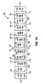
- FIG. 1A is a plan view of an exemplary blank 100 used to form a construct 144 (illustrated in FIG. 1D ) according to various aspects of the invention.
- the construct 144 FIG. 1D
- the construct 144 may be used to support one or more food items in a generally vertical, upstanding configuration during shipping, storage, heating, and/or serving. In this manner, the items are generally separated from one another, thereby minimizing damage to, and/or facilitating heating of, the food items.
- the blank 100 is a generally elongate strip comprising a plurality of first and second separator panels 102, 104 foldably connected along transverse spine fold lines 106.
- the separator panels 102, 104 are arranged in pairs 108 that form divider walls 146 in a construct 144 ( FIG. 1D ) erected from the blank 100.
- the exemplary blank 100 of FIG. 1A includes five panel pairs 108, with adjacent panel pairs 108 connected to one another by base panels 110 or 112. However, fewer or more panel pairs 108 can be included if desired, depending upon the number of food items to be stored and/or heated within the construct 144.
- a distal base panel 114 is foldably connected to a panel pair 108 at each end of the blank 100.
- An end panel 116 may be foldably connected at each end of the blank 100.
- the blank 100 may be wholly or partially symmetrical about a longitudinal center line CL .
- one base panel 110 is located to the left of base panel 112 , which is symmetrical about a transverse centerline CT , and two base panels 110 are located to the right of symmetrical base panel 112 .
- the base panel 110 to the left of the base panel 112 is a mirror image of the base panels 110 to the right.
- the separator panel pairs 108 to the left of symmetrical base panel 112 are mirror images of the separator panel pairs 108 to the right of symmetrical base panel 112.
- the base panels 110 include first and second locking features 118, 120 at each end of each panel 110.
- Each first locking feature 118 is defined in part by a curved or arcuate cut 122 that may be coterminous with a transverse cut 124. It will be understood that each cut disclosed herein may more specifically be in the form of a slit.
- Each second locking feature 120 is defined in part by a curved or arcuate cut 126 and an oblique cut 128 extending from an end of the curved cut 126.
- the curved cut 126 and the oblique cut 128 define a locking projection 130 of the second locking feature 120.
- Elongate, generally rectangular center sections 132 of the base panels 110 are foldably connected to adjacent first separator panels 102 along transverse fold lines 134, and foldably connected to adjacent second separator panels 104 along transverse fold lines 138.
- the symmetrical base panel 112 may have a pair of the first locking features 118 at each end of the panel 112. Additionally, the symmetrical base panel 112 includes an elongate, generally rectangular center section 136 foldably connected to adjacent second separator panels 104 along transverse fold lines 138. Likewise, elongate, generally rectangular center sections 140 of the distal base panels 114 are foldably connected to an adjacent first separator panel 102 along transverse fold line 134, and to an adjacent end panel 116 along transverse fold line 142. A second locking feature 120 is located at each end of each of the distal base panels 114.
- any of the various fold lines described herein or contemplated hereby may be any substantially linear, although not necessarily straight, form of disruption or weakening that facilitates folding or bending of the blank therealong.
- transverse fold lines 134, 138, and 142 are shown schematically in FIG. 1A as cut-crease lines.
- such lines and any of the others herein may be score lines, crease lines, a cut or a series of cuts that extend partially into and/or completely through the material along a desired line of weakness, or various combinations of these features.
- FIGS. 1A-1D One exemplary method of erecting a construct 144 from the blank 100 will now be discussed with reference to FIGS. 1A-1D .
- the ends of the blank 100 are advanced toward one another in the direction of the arrows so that the blank 100 folds along transverse fold lines 134 and 138.
- separator panels 102, 104 fold with respect to one another along transverse spine fold line 106.
- the second locking features 120 at one side of the base panel 110 slide through the cuts 124 extending along the transverse fold line 138.
- the locking projections 130 of the second locking feature 120 maintain the base panels 110 and 112 in the overlapping, interlocked position shown in FIGS. 1C and 1D with locking feature 120 overlying locking feature 118.
- the separator panels 102 and 104 With the base panels 110 and 112 engaged, the separator panels 102 and 104 are vertical or generally upright and form a separator wall 146. In the same manner, additional separator walls 146 may be formed from the other separator panel pairs 108 of the blank 100.
- FIG. 1D illustrates an exemplary construct 144 formed from the blank 100 of FIG. 1A , with each of the panel pairs 108 formed into separator walls 146 and end panels 116 folded upwardly about transverse fold lines 142.
- the separator walls 146 and the upright end panels 116 collectively form a plurality of receptacle slots 148 (that may generally resemble an accordion shape) in which one or more food items F may be received in a generally vertical, upstanding configuration.
- the end panel 116 in the foreground of FIG. 1D is shown partially cut away to illustrate a portion of the food item F in the foremost receptacle slot 148.
- the interlocked base panels 110, 112, and 114 of the blank 100 form a base 150 on which the food items may be seated within the construct 144.
- the construct 144 can be erected from the blank 100 without the use of glue or other adhesives. According to another aspect, after the construct 144 has been erected, the separator walls 146 and the end panels 116 can be folded over so the construct 144 can be shipped flat.
- the construct 144 may be placed into an outer container or carton 152, as shown in FIG. 1D .
- the carton 152 is a generally parallelepipedal structure having opposed side walls 154, end walls 156, a bottom wall 158, and an open top 160 through which the construct 144 is placed in the carton 152.
- other carton shapes and configuration are contemplated hereby. It will be understood that, in the present specification, a "panel,” “base” or “wall” need not be flat or otherwise planar.
- a “panel”, “base”, or “wall” can, for example, comprise a plurality of interconnected generally flat or planar sections. If desired, the carton 152 may be dimensioned such that various walls of the carton assist with maintaining the construct 144 in its upright, locked position.
- all or a portion of the various blanks, constructs, and/or containers may be formed, for example, at least partially from a paperboard material.
- the various blanks, constructs, and/or containers may be formed from paperboard having a basis weight of from about 97.65 to about 537.08 g/m 2 (60 to about 330 lbs/ream (lbs/3000 sq. ft)), for example, from about 130.2 to about 227.85 g/m 2 (80 to about 140 lbs/ream).
- the paperboard generally may have a thickness of from about 0.152 to about 0.762 mm (6 to about 30 mils), for example, from about 0.305 to about 0.711 mm (12 to about 28 mils).
- the paperboard has a thickness of about 0.305 mm (12 mils).
- Any suitable paperboard may be used, for example, a solid bleached or solid unbleached sulfate board, such as SUS® board, commercially available from Graphic Packaging International.
- the various blanks, constructs, and/or containers may comprise a paper or paper-based material generally having a basis weight of from about 24.41 to about 97.65 g/m 2 (15 to about 60 lbs/ream), for example, from about 32.55 to about 65.1 g/m 2 (20 to about 40 lbs/ream).
- the paper has a basis weight of about 40.69 g/m 2 (25 lbs/ream).
- microwave energy interactive elements may overlie and/or be joined to at least a portion of any of the various blanks and/or constructs of the invention.
- Each microwave interactive element may comprise one or more microwave energy interactive materials or segments arranged in a particular configuration to absorb microwave energy, transmit microwave energy, reflect microwave energy, or direct microwave energy, as needed or desired for a particular microwave heating application.
- one or more of the elements may promote browning and/or crisping of the food item, shield the food item from microwave energy to prevent overcooking the food item in that area, or transmit microwave energy towards or away from a particular portion of the food item.
- the microwave interactive element may be supported on a microwave inactive or transparent substrate for ease of handling and/or to prevent contact between the microwave interactive material and the food item.
- a microwave interactive element supported on a microwave transparent substrate includes both microwave interactive and microwave inactive elements or components, such structures may be referred to herein as "microwave interactive webs".
- the microwave energy interactive material may comprise an electroconductive or semiconductive material, for example, a metal or a metal alloy provided as a metal foil; a vacuum deposited metal or metal alloy; or a metallic ink, an organic ink, an inorganic ink, a metallic paste, an organic paste, an inorganic paste, or any combination thereof.
- metals and metal alloys that may be suitable for use with the present invention include, but are not limited to, aluminum, chromium, copper, inconel alloys (nickel-chromium-molybdenum alloy with niobium), iron, magnesium, nickel, stainless steel, tin, titanium, tungsten, and any combination or alloy thereof.
- the microwave energy interactive material may comprise a metal oxide.
- metal oxides that may be suitable for use with the present invention include, but are not limited to, oxides of aluminum, iron, and tin, used in conjunction with an electrically conductive material where needed.
- ITO indium tin oxide
- ITO can be used as a microwave energy interactive material to provide a heating effect, a shielding effect, a browning and/or crisping effect, or a combination thereof.
- ITO may be sputtered onto a clear polymeric film. The sputtering process typically occurs at a lower temperature than the evaporative deposition process used for metal deposition.
- ITO has a more uniform crystal structure and, therefore, is clear at most coating thicknesses. Additionally, ITO can be used for either heating or field management effects. ITO also may have fewer defects than metals, thereby making thick coatings of ITO more suitable for field management than thick coatings of metals, such as aluminum.
- the microwave energy interactive material may comprise a suitable electroconductive, semiconductive, or non-conductive artificial dielectric or ferroelectric.
- Artificial dielectrics comprise conductive, subdivided material in a polymeric or other suitable matrix or binder, and may include flakes of an electroconductive metal, for example, aluminum.
- the microwave interactive element may comprise a thin layer of microwave interactive material that tends to absorb microwave energy, thereby generating heat at the interface with a food item.
- Such elements often are used to promote browning and/or crisping of the surface of a food item (sometimes referred to as a "browning and/or crisping element").
- a susceptor film When supported on a film or other substrate, such an element may be referred to as a "susceptor film” or, simply, "susceptor”.
- the microwave interactive element may comprise a foil having a thickness sufficient to shield one or more selected portions of the food item from microwave energy (sometimes referred to as a "shielding element").
- shielding elements may be used where the food item is prone to scorching or drying out during heating.
- the shielding element may be formed from various materials and may have various configurations, depending on the particular application for which the shielding element is used.
- the shielding element is formed from a conductive, reflective metal or metal alloy, for example, aluminum, copper, or stainless steel.
- the shielding element generally may have a thickness of from about 7.24 ⁇ m to about 1.27 mm (0.000285 inches to about 0.05 inches). In one aspect, the shielding element has a thickness of from about 7.62 ⁇ m to about 0.76 mm (0.0003 inches to about 0.03 inches). In another aspect, the shielding element has a thickness of from about 8.89 ⁇ m to about 0.51 mm (0.00035 inches to about 0.020) inches, for example, 0.406 mm (0.016 inches).
- the microwave interactive element may comprise a segmented foil, such as, but not limited to, those described in U.S. Patent Nos. 6,204,492 , 6,433,322 , 6,552,315 , and 6,677,563 , each of which is incorporated by reference in its entirety.
- segmented foils are not continuous, appropriately spaced groupings of such segments often act as a transmitting element to direct microwave energy to specific areas of the food item.
- Such foils also may be used in combination with browning and/or crisping elements, for example, susceptors.
- any of the above microwave energy interactive elements used in accordance with the invention may be supported on a substrate.
- the substrate typically comprises an electrical insulator, for example, a film formed from a polymer or polymeric material.
- polymer or “polymeric material” includes, but is not limited to, homopolymers, copolymers, such as for example, block, graft, random, and alternating copolymers, terpolymers, etc. and blends and modifications thereof.
- the term polymer shall include all possible geometrical configurations of the molecule. These configurations include, but are not limited to isotactic, syndiotactic, and random symmetries.
- the thickness of the film typically may be from about 8.89 to about 2.54 ⁇ m (35 gauge to about 10 mil). In one aspect, the thickness of the film is from about 10.16 to about 20.32 ⁇ m (40 to about 80 gauge). In another aspect, the thickness of the film is from about 11.43 to about 12.7 ⁇ m (45 to about 50 gauge). In still another aspect, the thickness of the film is about 12.18 ⁇ m (48 gauge).
- polymeric films that may be suitable include, but are not limited to, polyolefins, polyesters, polyamides, polyimides, polysulfones, polyether ketones, cellophanes, or any combination thereof. Other non-conducting substrate materials such as paper and paper laminates, metal oxides silicates, cellulosics, or any combination thereof, also may be used.
- the polymer film may be selected to impart various properties to the microwave interactive web, for example, printability, heat resistance, or any other property.
- the polymeric film comprises polyethylene terephthalate (PET).
- PET polyethylene terephthalate
- Polyethylene terephthalate films are used in commercially available susceptors, for example, the QWIKWAVE ® Focus susceptor and the MICRORITE ® susceptor, both available from Graphic Packaging International (Marietta, Georgia).
- Examples of polyethylene terephthalate films that may be suitable for use as the substrate include, but are not limited to, MELINEX ® , commercially available from DuPont Teijan Films (Hopewell, Virginia), SKYROL, commercially available from SKC, Inc. (Covington, Georgia), and BARRIALOX PET, commercially available from Toray Films (Front Royal, VA), and QU50 High Barrier Coated PET, available from Toray Films (Front Royal, VA).
- the microwave energy interactive material may be applied to the substrate in any suitable manner, and in some instances, the microwave energy interactive material is printed on, extruded onto, sputtered onto, evaporated on, or laminated to the substrate.
- the microwave energy interactive material may be applied to the substrate in any pattern, and using any technique, to achieve the desired heating effect of the food item.
- the microwave energy interactive material may be provided as a continuous or discontinuous layer or coating including circles, loops, hexagons, islands, squares, rectangles, octagons, and so forth. Examples of various patterns and methods that may be suitable for use with the present invention are provided in U.S. Patent Nos.
- FIG. 1E illustrates a blank 162 similar to the blank 100 of FIG. 1A , except that the blank 162 of FIG. 1E includes a microwave energy interactive element 164 overlying substantially all of the various panels.
- the microwave energy interactive element 164 comprises a susceptor and, more particularly, comprises a susceptor film including a microwave energy interactive material 166 supported on a polymer film 168, as shown schematic cross-sectional view of FIG.1F .
- the layer of microwave energy interactive material 166 is disposed between the polymer film 168 and the paperboard support 170 that forms the various panels of the blank 162.
- the susceptor film 164 may be joined to the support in any suitable manner, for example, using a continuous or patterned layer of adhesive (not shown). However, other microwave energy interactive elements are contemplated hereby.
- a construct may be formed from the blank 162 in the manner described above, and would be similar to that of FIG. 1D , except that the microwave energy interactive element 164, in this example, a susceptor, would overlie the food-contacting side of the various panels.
- one or more food items may be loaded into the construct and, optionally, placed within an outer container, as generally shown in FIG. 1D .
- the food items may remain in this condition prior to consumption.
- the construct optionally within an outer container, may be placed within a microwave oven (not shown).
- the food items remain in proximate and/or intimate contact with the susceptor.
- the susceptor converts microwave energy to thermal energy, which then may be transferred to the adjacent food item. As a result, the heating, browning, and/or crisping of the food item or items may be enhanced.
- the inner surface of the container also may include one or more microwave energy interactive elements (not shown) to enhance further, or otherwise alter, the effect of microwave oven on the food items.
- any of the numerous microwave interactive elements described herein or contemplated hereby may be substantially continuous, that is, without substantial breaks or interruptions, or may be discontinuous, for example, by including one or more breaks or apertures that transmit microwave energy therethrough.
- the breaks or apertures may be sized and positioned to heat particular areas of the food item selectively. The number, shape, size, and positioning of such breaks or apertures may vary for a particular application depending on type of construct being formed, the food item to be heated therein or thereon, the desired degree of shielding, browning, and/or crisping, whether direct exposure to microwave energy is needed or desired to attain uniform heating of the food item, the need for regulating the change in temperature of the food item through direct heating, and whether and to what extent there is a need for venting.
- the aperture may be a physical aperture or void in the material used to form the blank or construct, or may be a non-physical "aperture" or discontinuity.
- a non-physical aperture may be a portion of the blank or construct that is microwave energy inactive by deactivation or otherwise, or one that is otherwise transparent to microwave energy.
- the aperture may be a portion of the blank or construct formed without a microwave energy active material or, alternatively, may be a portion of the blank or construct formed with a microwave energy active material that has been removed or deactivated. While both physical and non-physical apertures or discontinuities allow the food item to be heated directly by the microwave energy, a physical aperture also provides a venting function to allow steam or other vapors to be released and carried away from the food item.
- the concentration of heat generated along the edges of adjacent panels, for example, panels 102 and 104 may be sufficient to cause the underlying support, for example, paperboard, to become scorched.
- the peripheral portions of one or more of panels 102, 104, and/or 110 may be designed to be microwave inactive, for example, by forming these areas without a microwave energy interactive material or by deactivating the microwave energy interactive material in these areas.
- one or more panels, portions of panels, or portions of the construct may be designed to be microwave energy inactive to ensure that the microwave energy is focused efficiently on the areas to be browned and/or crisped, rather than being lost to portions of the food item not intended to be browned and/or crisped or to the heating environment.
- a plurality of microwave energy interactive elements 164 for example, microwave energy interactive susceptor "patches" of varying size, overlie a non-peripheral portion of each of panels 102 and 104, but do not overlie panels 110. Numerous other configurations are contemplated by the invention.
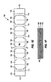
- FIG. 2 illustrates another exemplary blank 200 according to various aspects of the invention.
- the blank 200 may be substantially similar to the blank 100 illustrated in FIG. 1A , with similar or identical elements to those of FIG. 1A being preceded by a "2" instead of a "1".
- the blank 200 may be wholly or partially symmetrical about a longitudinal center line CL.
- the blank 200 is an elongate strip comprising a plurality of first and second separator panels 202, 204 foldably connected along transverse spine fold lines 206.
- the separator panels 202, 204 are arranged in pairs 208 that form divider walls in the erected construct (not shown).
- the exemplary blank 200 includes five panel pairs 208, with adjacent panel pairs 208 connected to one another at base panels 210 or 212.
- a distal base panel 214 is foldably connected to a panel pair 208 at each end of the blank 200.
- An end panel 216 may be foldably connected at each end of the blank 200.
- the second locking features 220 of FIG. 2 may be substantially identical to the second locking features 120 illustrated in FIG. 1A .
- the first locking features 218 may be similar to the locking features 118 illustrated in FIG. 1A , except that cut 224 extending from an end of each of the curved cuts 222 is an oblique cut.
- Oblique cuts 224 and curved cuts 222 define locking projections 262 that engage corresponding locking projections 230 in the second locking features 220 to secure adjacent base panels.
- a microwave energy interactive element 264 for example, a susceptor, may overlie all or a portion of the blank 200.
- the blank 200 may be erected into a construct and used in the manner described above with reference to FIGS. 1A-1G . Further, the construct may be used with a carton or other container as described above to contain, heat, brown, and/or crisp one or more food items, as described in connection with FIG. 1D .
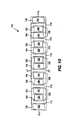
- FIG. 3A illustrates yet another exemplary blank 500 according to various aspects of the invention.
- the blank 500 may be wholly or partially symmetrical about a longitudinal center line CL.
- the blank 500 is a generally elongate strip comprising a plurality of first and second separator panels 502, 504 foldably connected along transverse spine fold lines 506.
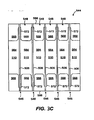
- the separator panels 502, 504 are arranged in separator panel pairs 508 that form divider walls 546 in a construct 544 erected from the blank 500 ( FIG. 3C ).
- the exemplary blank 500 includes five separator panel pairs 508, with adjacent panel pairs 508 connected to one another at base panels 510. However, fewer or additional separator panel pairs 508 can be included depending upon the number of food items to be stored and/or heated within the construct 544.
- Base panels 510 are elongate, generally rectangular sections foldably connected to adjacent first separator panels 502 along transverse fold lines 534, and foldably connected to adjacent second separator panels 504 along transverse fold lines 536.
- a locking feature 518 is located at an upper and a lower marginal area of the blank 500.
- the locking features 518 are each foldably connected to each end of one of the base panels 510 along a longitudinal fold line 566.
- Each locking feature 518 includes a plurality of locking projections 568 extending from a base 570.
- the locking features 518 are separated from one another by elongated clearance apertures 572.
- the base 570 of each locking feature 518 is separated from the respective adjacent separator panel 502, 504 by longitudinal cuts 574.
- Clearance cutouts 576, 578 are formed in the separator panels 502, 504. The clearance cutouts 576, 578 allow the locking features 518 to be folded inwardly about the fold lines 566, as will be discussed further below with reference to FIG. 3B .
- a microwave energy interactive element 564 for example, a susceptor, may overlie all or a portion of the blank 500.
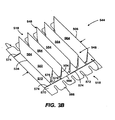
- separator panels 502, 504 assume generally upright positions and form separator walls 546, as shown in FIG. 3 B.
- Locking features 518 are then folded 180 degrees inwardly about the longitudinal fold lines 566 in the direction of the curved arrows until the locking features 518 are folded flat as shown in FIG.3C .
- the clearance cutouts 576, 578 in the separator panels 502, 504 allow the bases 570 of the locking features 518 to fold over without interfering with the remainder of the construct.
- the upright separator walls 546 pass through the clearance apertures 572 in the locking features 518.
- the separator walls 546 form a plurality of receptacle slots 548 in which food items (not illustrated) may be received.
- the construct 544 can be erected from the blank 500 without the use of glue or other adhesives.
- the construct can be used in the manner described above with respect to the various other constructs of the invention to contain and, optionally, heat, brown, and/or crisp one or more food items in a microwave oven.
- the blank, constructs, and/or outer carton may include a microwave energy interactive element comprising a microwave energy interactive insulating material.
- microwave energy interactive insulating material or “microwave energy interactive insulating structure” or “insulating material” or “insulating structure” refers any combination of layers of materials, for example, paper layers, polymer film layers, and microwave energy interactive elements, that is both responsive to microwave energy and capable of providing some degree of thermal insulation when used to heat a food item.
- the insulating material may overlie all or a portion of the various food-contacting areas of the various blanks, constructs, and/or cartons, for example, in place of the susceptors shown in the various figures. However, other locations for the insulating material are contemplated hereby.
- the insulating material may include various components, provided that each is resistant to softening, scorching, combusting, or degrading at typical microwave oven heating temperatures, for example. at from about 121°C to about 218°C (250°F to about 425°F).
- the insulating material may include both microwave energy responsive or interactive components, and microwave energy transparent or inactive components.
- the insulating material comprises one or more susceptor layers in combination with one or more expandable insulating cells. Such materials may be referred to as "expandable cell insulating materials". Additionally, the insulating material may include one or more microwave energy transparent or inactive materials to provide dimensional stability, to improve ease of handling the microwave energy interactive material, and/or to prevent contact between the microwave energy interactive material and the food item.
- an insulating material may comprise a microwave energy interactive material supported on a first polymeric film layer, a moisture-containing layer superposed with the microwave energy interactive material and a second polymeric film layer joined to the moisture-containing layer in a predetermined pattern, thereby forming one or more closed cells between the moisture-containing layer and the second polymeric film layer. The closed cells expand or inflate in response to being exposed to microwave energy, and thereby causing microwave energy interactive material to bulge and deform.
- FIGS. 4A-10 Several exemplary insulating materials are depicted in FIGS. 4A-10.
- the layer widths are not necessarily shown in perspective.
- some layers may be very thin with respect to other layers, but are nonetheless shown with some thickness for purposes of clearly illustrating the arrangement of layers.
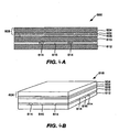
- FIG.4A depicts an exemplary insulating structure or material 600 that may be used in accordance with the invention.
- a thin layer of microwave energy interactive material 602 is supported on a first polymer film 604 (collectively comprising susceptor 606) and bonded by lamination with an adhesive 608 (or otherwise) to a dimensionally stable substrate 610, for example, paper.
- the substrate 610 is bonded to a second polymer film 612 using a patterned adhesive 614 or other material, such that closed, expandable cells 616 (each shown as a void) are formed in the material 600.
- the insulating material 600 may be cut and provided as a substantially flat, multi-layered sheet 618, as shown in FIG. 4 B.
- the microwave energy interactive material 602 heats upon impingement by microwave energy, water vapor and other gases typically held in the substrate 610, for example, paper, and any air trapped in the thin space between the second polymer film 612 and the substrate 610 in the closed cells 616, expand, as shown in Fig. 4C .
- the resulting insulating material 618' has a quilted or pillowed top surface 620 and bottom surface 622.
- the cells 626 typically deflate and return to a somewhat flattened state.
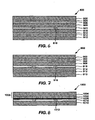
- FIG. 5 illustrates another exemplary microwave energy interactive insulating structure or material 700 that may be used in accordance with the invention.
- the structure 700 of FIG. 5 includes a thin layer of microwave energy interactive material 702 supported on a first polymer film 704, which collectively comprises susceptor 706.
- Susceptor 706 is bonded by lamination with an adhesive 708 or otherwise to a dimensionally stable substrate 710, for example, paper, which in turn, is bonded to a second polymer film 712 using a patterned adhesive 714 or other material to form a plurality of closed, expandable cells 716 (each shown as a void).
- the structure 700 includes an additional layer of paper 718 joined to the remainder of the structure using a layer of adhesive 720 or other suitable material to provide additional dimensional stability and to prevent any flaking of the microwave energy interactive material 702 from the structure 700.
- FIG. 6 depicts yet another exemplary insulating structure or material 800 that may be used in accordance with the invention.
- the material 800 includes two symmetrical layer arrangements adhered together by a patterned adhesive layer.
- the first symmetrical layer arrangement begins at the top of the drawings, comprises a polymer film layer 802, for example, polyethylene terephthalate, a metal layer 804, an adhesive layer 806, and a paper or paperboard layer 808.
- the metal layer 804 may comprise a metal, such as aluminum, deposited along at least a portion of the polymer film layer 802.
- the polymer film layer 802 and metal layer 804 together define a susceptor.
- the adhesive layer 806 bonds the polymer film layer 802 and the metal layer 804 to the paperboard layer 808.
- the second symmetrical layer arrangement also comprises a polymer film layer 810, a metal layer 812, an adhesive layer 814, and a paper or paperboard layer 816. If desired, the two symmetrical arrangements may be formed by folding one layer arrangement onto itself. The layers of the second symmetrical layer arrangement are bonded together in a similar manner as the layers of the first symmetrical arrangement.
- a patterned adhesive layer 818 is provided between the two paper layers 808 and 816, and defines a pattern of closed cells 820 (each shown as a void) configured to expand when exposed to microwave energy.
- the material 900 includes a polymer film layer 902, a metal layer 904, an adhesive layer 906, and a paper layer 908. Additionally, the material 900 may include a second polymer film layer 910, an adhesive 912, and a paper layer 914. The layers are adhered or affixed by a patterned adhesive 916 to define a plurality of closed expandable cells 918 (each shown as a void).
- FIG. 8 depicts yet another exemplary insulating material 1000.
- one or more reagents are used to generate a gas that expands the cells of the insulating material.
- a thin layer of microwave interactive material 1002 is supported on a first polymer film 1004 to form a susceptor film 1006.
- One or more reagents 1008, optionally within a coating, overlie at least a portion of the layer of microwave interactive material 1002.
- the reagent 1008 is joined to a second polymer film 1010 using a patterned adhesive 1012 or other material, or using thermal bonding, ultrasonic bonding, or any other suitable technique, such that closed cells 1014 (each shown as a void) are formed in the material 1000.
- the microwave interactive material 1002 heats upon impingement by microwave energy, water vapor or other gases are released from or generated by the reagent 1008.
- the resulting gas applies pressure on the susceptor film 1006 on one side and the second polymer film 1010 on the other side of the closed cells 1014.
- Each side of the material 1000 forming the closed cells 1014 reacts simultaneously, but uniquely, to the heating and vapor expansion to form a quilted insulating material (not shown, but similar in appearance to that of FIG. 4C ). This expansion may occur within 1 to 15 seconds in an energized microwave oven, and in some instances, may occur within 2 to 10 seconds.
- Even without a paper or paperboard layer, the water vapor resulting from the reagent is sufficient both to inflate the expandable cells and to absorb any excess heat from the microwave energy interactive material.
- the various insulating materials of the present invention may enhance heating, browning, and/or crisping of a food item in a microwave oven.
- the water vapor, air, and other gases contained in the closed cells provide insulation between the food item and the ambient environment of the microwave oven, thereby increasing the amount of sensible heat that stays within or is transferred to the food item.
- the formation of the cells allows the material to conform more closely to the surface of the food item, placing the susceptor film in greater proximity to the food item, thereby enhancing browning and/or crisping.
- insulating materials may help to retain moisture in the food item when cooking in the microwave oven, thereby improving the texture and flavor of the food item. Additional benefits and aspects of such materials are described in PCT Application No. PCT/US03/03779 , U.S. Application No. 10/501,003 , and U.S. Application No. 11/314,851 , each of which is incorporated by reference herein in its entirety.
- any of the insulating materials described herein or contemplated hereby may include an adhesive pattern or thermal bond pattern that is selected to enhance cooking of a particular food item.
- the adhesive pattern may be selected to form substantially uniformly shaped expandable cells.
- the adhesive pattern may be selected to form a plurality of different sized cells to allow the item to be variably contacted on its various surfaces. While several examples are provided herein, it will be understood that numerous other patterns are contemplated hereby, and the pattern selected will depend on the heating, browning, crisping, and insulating needs of the particular food item.
- multiple layers of insulating materials may be used to enhance the insulating properties of the insulating material and, therefore, enhance the browning and crisping of the food item.
- the layers may remain separate or may be joined using any suitable process or technique, for example, thermal bonding, adhesive bonding, ultrasonic bonding or welding, mechanical fastening, or any combination thereof.
- two sheets of an insulating material may be arranged so that their respective susceptor film layers are facing away from each other.
- two sheets of an insulating material may be arranged so that their respective susceptor film layers are facing towards each other.
- multiple sheets of an insulating material may be arranged in a like manner and superposed.
- multiple sheets of various insulating materials may be superposed in any other configuration as needed or desired for a particular application.
- one or more portions of the various blanks, constructs, and/or systems described herein or contemplated hereby may be coated with varnish, clay, or other materials, either alone or in combination.
- the coating may then be printed over with product advertising or other information or images.
- the various blanks, constructs, and/or systems also may be coated to protect any information printed thereon.
- any of the blanks, constructs, and/or systems of the present invention may be coated or laminated with other materials to impart other properties, such as absorbency, repellency, opacity, color, printability, stiffness, or cushioning.
- absorbent susceptors are described in U.S. Provisional Application No. 60/604,637, filed August 25, 2004 , and U.S. Patent Application No. 11/211,858, to Middleton, et al. , titled “Absorbent Microwave Interactive Packaging", filed August 25, 2005, both of which are incorporated herein by reference in their entirety.
- the constructs may include graphics or indicia printed thereon.
- the microwave interactive element may have a grey or silver color this is visually distinguishable from the substrate or the support.
- the present invention contemplates using a silver or grey toned adhesive to join the microwave interactive elements to the substrate, using a silver or grey toned substrate to mask the presence of the silver or grey toned microwave interactive element, using a dark toned substrate, for example, a black toned substrate, to conceal the presence of the silver or grey toned microwave interactive element, overprinting the metallized side of the web with a silver or grey toned ink to obscure the color variation, printing the non-metallized side of the web with a silver or grey ink or other concealing color in a suitable pattern or as a solid color layer to mask or conceal the presence of the microwave interactive element, or any other suitable technique or combination thereof.
- joinder references are to be construed broadly and may include intermediate members between a connection of elements and relative movement between elements. As such, joinder references do not necessarily imply that two elements are connected directly and in fixed relation to each other.
Description
- The present invention relates to a construct according to the preamble of
claim 1. Moreover the present invention relates to a blank for forming such construct. More generally, the present invention concerns constructs, blanks, packages, and systems for supporting one or more food items, which blanks, constructs, packages, and systems include features for heating, browning, and/or crisping such food items in a microwave oven. - Microwave ovens provide a convenient means of preparing a food item for consumption by a user. However, microwave ovens tend to cook such items unevenly and often are not capable of achieving a comparable level of browning and/or crisping of some food items that might be attained using a conventional oven, toaster oven, or toaster, particularly dough-based or breaded food items. At the same time, such appliances often require greater time to pre-heat and/or prepare such food items. Additionally, in some circumstances, such appliances are not convenient to a user and/or are not permitted to be used. For example, many universities, hospitals, hotels, workplaces, and other institutions do not permit residents to use a toaster, toaster oven, or conventional oven within individual rooms or offices. However, many of such institutions allow use of a microwave oven, either within individual rooms or offices, or in shared areas, such as kitchens, cafeterias, or break rooms. As such, there is a continuing need for materials, constructs, and systems that enable a user to prepare toast, waffles, French toast, bagels, English muffins, sandwiches, pastries, breaded meats, and other items that are desirably browned and/or crisped in a microwave oven. There is also a need for containing one or more food items in a separated configuration before, during, and/or after heating.
-
US 5175404 A discloses a construct of the generic type as defined in the preamble ofclaim 1 which construct is in the form of a food heating package with partitions formed from microwave energy absorbing material to heat the food items received in the receptacles formed between the partitions. According to one embodiment the partitions, which are spaced from one another by base panels, may be formed from two separator panels. The two separator panels are bonded together by adhesive located between them in order to maintain said separator panels in a facing relationship with one another. Additionally, the sheet with the folded partitions is bonded by adhesive to a lower unfolded sheet. -
JP 10310127 A -
US 1913655 A deals with egg packages having divider walls formed from two separator panels, essentially facing one another. As regards locking means, one of the embodiments of this reference suggests a structure quite similar to that ofUS 5175404 A . -
US 4935592 A discloses a microwave oven cooking construct with divider walls each formed from two separator panels, each two adjacent divider walls being connected by a base panel. However, this document is absolutely silent as to any locking engagement of the first and second base panel for maintaining the first separator panel and the second separator panel in a substantially facing relationship with one another. Apparently, there is no need for such locking since the construct is used in connection with a carton such that either the construct is attached to the carton bottom or the construct fits snugly in the carton. -
US 4748308 A deals with a microwave oven toaster. The toaster comprises a block of microwave transparent material including a plurality of parallel and aligned slots therein for receiving cards of material which absorb microwave energy. Pieces of bread received in the receptacles between each two adjacent microwave energy absorbing cards may be browned in a microwave oven. - The present invention is directed to provide for an improved construct of the generic type to be used in preparation of food in a microwave oven.
- This object is achieved by the construct of the present invention as defined in
claim 1. Preferred embodiments are defined in the sub-claims. - The present invention is directed generally to various blanks, constructs, packages, and systems for supporting one or more food items. The various constructs may be used to contain the food items and heat, brown, and/or crisp the food items in a microwave oven. The various blanks, constructs, packages, and systems of the invention include features that alter the effect of microwave energy on the food items. Such blanks, constructs, packages and systems also may facilitate storage of a plurality of food items that are desirably separated from one another.
- In one exemplary aspect, the invention is directed to a construct for supporting a plurality of food items. The construct includes a plurality of divider walls and a plurality of base panels. The divider walls are spaced from one another along a length of the construct. Each base panel is located between a pair of adjacent divider walls and connecting the adjacent divider walls. If desired, the construct may be retained within at least four walls of a carton.
- Each divider wall comprises a pair of foldably connected separator panels. Each pair of separator panels may comprise a first separator panel foldably connected to a second separator panel at a spine fold line. In one example, the separator panels are substantially upright. In another example, the separator panels are substantially upright and the base panels are substantially transverse to the separator panels. In yet another example, the separator panels are substantially flattened and the base panels are substantially parallel with the separator panels.
- The first separator panel may be folded about the spine fold line of the separator panel pair so that it is adjacent to the second separator panel of the pair. For each pair of separator panels, the first separator panel may be foldably connected to a first base panel of the base panels, and the second separator panel may be foldably connected to a second base panel of the base panels. The first base panel may be interlocked with the second base panel.
- The first base panel is interlocked with the second base panel at a locking feature located at an edge of the construct.
- In another variation, the construct comprises at least one locking feature, where each locking feature comprises a plurality of locking projections. Each locking projection may extend between two adjacent divider walls and may overlie at least one of the base panels. The at least one locking feature may be foldably connected to one of the base panels.
- In still another variation, each of the first separator panel and the second separator panel have a first surface, and a microwave energy interactive material overlies at least a portion of the first surface of the first separator panel and at least a portion of the first surface of the second separator panel. In one example, the microwave energy material element forms a susceptor.
- In another exemplary aspect, the invention is directed to a blank for forming a construct for containing one or more food items therein. The blank has a longitudinal dimension and a transverse dimension and comprises a plurality of separator panel pairs and a plurality of base panels. Each pair of separator panels comprises a first separator panel foldably connected to a second separator panel at a transverse spine fold line. Each base panel connects a separator panel of one separator panel pair to a separator panel of an adjacent separator panel pair along at least one a transverse fold line.
- Each base panel may comprise a substantially rectangular center section. Each base panel also may comprise at least one locking feature. In one variation, each base panel comprises a first locking feature at one side of the base panel and a second locking feature at a second side of the base panel. In another variation, the locking feature comprises a plurality of locking projections. In an example of this variation, the locking projections extend along the transverse direction. In still another variation, the at least one locking feature may be foldably connected to one of the base panels.
- A microwave energy interactive element including a microwave energy interactive material may overlie at least a portion of at least one of the separator panel pairs. In one example, the first separator panel and the second separator panel each comprise a food-contacting side, a first microwave energy interactive element overlies at least a portion of the food-contacting side of the first separator panel, and a second microwave energy interactive element overlies at least a portion of the food-contacting side of the second separator panel. In another example, the first microwave energy interactive element and the second microwave energy interactive element each comprise a layer of microwave energy interactive material that converts microwave energy into thermal energy.
- Other aspects, features, and advantages of the invention will become apparent from the following description and accompanying figures.
- The description refers to the accompanying drawings, some of which are schematic. According to common practice, the various features of the drawings discussed below are not necessarily drawn to scale. Dimensions of various features and elements in the drawings may be expanded or reduced to illustrate the features of the invention more clearly.
-
FIG. 1A is a plan view of an exemplary blank according to various aspects of the invention; -
FIG. 1B is a detail view of a portion of the blank ofFIG. 1A ; -
FIG. 1C illustrates a portion of the blank ofFIG. 1A , partially erected into a construct; -
FIG. 1D illustrates an exemplary construct erected from the blank ofFIG. 1A in an exploded configuration with respect to an outer carton, according to various aspects of the invention; -
FIG. 1E is a plan view of the blank ofFIG. 1A , with a microwave energy interactive element, according to various aspects of the invention; -
FIG. 1F is a schematic, partial cross-sectional view of the blank ofFIG. 1E ; -
FIG. 1G is a plan view of the blank ofFIG. 1A , with a plurality of microwave energy interactive elements, according to various aspects of the invention; -
FIG. 2 is a plan view of another exemplary blank according to the various aspects of the invention; . -
FIG. 3A is a plan view of another exemplary blank according to various aspects of the invention; -
FIG. 3B illustrates the blank ofFIG. 3A , partially erected into a construct; -
FIG. 3C is a top plan view of an exemplary construct erected from the blank ofFIG. 3A , according to various aspects of the invention; -
FIG. 4A is a schematic cross-sectional view of an exemplary microwave energy interactive insulating material that may be used in accordance with the invention; -
FIG. 4B is a schematic perspective view of the insulating material ofFIG. 4A , in the form of a cut sheet; -
FIG. 4C is a schematic perspective view of the insulating material ofFIG. 4B , during exposure to microwave energy; -
FIG. 5 is a schematic cross-sectional view of another exemplary microwave energy interactive insulating material that may be used in accordance with the invention; -
FIG. 6 is a schematic cross-sectional view of yet another exemplary microwave energy interactive insulating material that may be used in accordance with the invention; -
FIG. 7 is a schematic cross-sectional view of still another exemplary microwave energy interactive insulating material that may be used in accordance with the invention; and -
FIG. 8 is a schematic cross-sectional view of another exemplary microwave energy interactive insulating material that may be used in accordance with the invention. - Various aspects of the invention may be illustrated by referring to the figures. Although several different exemplary aspects, implementations, and embodiments of the various inventions are provided, numerous interrelationships between, combinations thereof, and modifications of the various inventions, aspects, implementations, and embodiments of the inventions are contemplated hereby.
-
FIG. 1A is a plan view of an exemplary blank 100 used to form a construct 144 (illustrated inFIG. 1D ) according to various aspects of the invention. In this and other aspects, the construct 144 (FIG. 1D ) may be used to support one or more food items in a generally vertical, upstanding configuration during shipping, storage, heating, and/or serving. In this manner, the items are generally separated from one another, thereby minimizing damage to, and/or facilitating heating of, the food items. - Viewing
FIG. 1A , the blank 100 is a generally elongate strip comprising a plurality of first andsecond separator panels separator panels pairs 108 that formdivider walls 146 in a construct 144 (FIG. 1D ) erected from the blank 100. Theexemplary blank 100 ofFIG. 1A includes five panel pairs 108, with adjacent panel pairs 108 connected to one another bybase panels construct 144. Adistal base panel 114 is foldably connected to apanel pair 108 at each end of the blank 100. Anend panel 116 may be foldably connected at each end of the blank 100. The blank 100 may be wholly or partially symmetrical about a longitudinal center line CL. - In the exemplary embodiment, one
base panel 110 is located to the left ofbase panel 112, which is symmetrical about a transverse centerline CT, and twobase panels 110 are located to the right ofsymmetrical base panel 112. Thebase panel 110 to the left of thebase panel 112 is a mirror image of thebase panels 110 to the right. Similarly, the separator panel pairs 108 to the left ofsymmetrical base panel 112 are mirror images of the separator panel pairs 108 to the right ofsymmetrical base panel 112. - The
base panels 110 include first and second locking features 118, 120 at each end of eachpanel 110. Eachfirst locking feature 118 is defined in part by a curved orarcuate cut 122 that may be coterminous with atransverse cut 124. It will be understood that each cut disclosed herein may more specifically be in the form of a slit. - Each
second locking feature 120 is defined in part by a curved orarcuate cut 126 and anoblique cut 128 extending from an end of thecurved cut 126. Thecurved cut 126 and the oblique cut 128 define a lockingprojection 130 of thesecond locking feature 120. Elongate, generallyrectangular center sections 132 of thebase panels 110 are foldably connected to adjacentfirst separator panels 102 alongtransverse fold lines 134, and foldably connected to adjacentsecond separator panels 104 along transverse fold lines 138. - The
symmetrical base panel 112 may have a pair of the first locking features 118 at each end of thepanel 112. Additionally, thesymmetrical base panel 112 includes an elongate, generallyrectangular center section 136 foldably connected to adjacentsecond separator panels 104 along transverse fold lines 138. Likewise, elongate, generallyrectangular center sections 140 of thedistal base panels 114 are foldably connected to an adjacentfirst separator panel 102 alongtransverse fold line 134, and to anadjacent end panel 116 alongtransverse fold line 142. Asecond locking feature 120 is located at each end of each of thedistal base panels 114. - It will be understood that any of the various fold lines described herein or contemplated hereby may be any substantially linear, although not necessarily straight, form of disruption or weakening that facilitates folding or bending of the blank therealong. For example,
transverse fold lines FIG. 1A as cut-crease lines. However, such lines and any of the others herein may be score lines, crease lines, a cut or a series of cuts that extend partially into and/or completely through the material along a desired line of weakness, or various combinations of these features. - One exemplary method of erecting a
construct 144 from the blank 100 will now be discussed with reference toFIGS. 1A-1D . As shown inFIG. 1C , the ends of the blank 100 are advanced toward one another in the direction of the arrows so that the blank 100 folds alongtransverse fold lines separator panels spine fold line 106. - As
base panels base panel 110 slide through thecuts 124 extending along thetransverse fold line 138. When theseparator panels projections 130 of thesecond locking feature 120 maintain thebase panels FIGS. 1C and1D with lockingfeature 120overlying locking feature 118. With thebase panels separator panels separator wall 146. In the same manner,additional separator walls 146 may be formed from the other separator panel pairs 108 of the blank 100. -
FIG. 1D illustrates anexemplary construct 144 formed from the blank 100 ofFIG. 1A , with each of the panel pairs 108 formed intoseparator walls 146 and endpanels 116 folded upwardly about transverse fold lines 142. Theseparator walls 146 and theupright end panels 116 collectively form a plurality of receptacle slots 148 (that may generally resemble an accordion shape) in which one or more food items F may be received in a generally vertical, upstanding configuration. Theend panel 116 in the foreground ofFIG. 1D is shown partially cut away to illustrate a portion of the food item F in theforemost receptacle slot 148. The interlockedbase panels base 150 on which the food items may be seated within theconstruct 144. - According to one aspect of the present invention, the
construct 144 can be erected from the blank 100 without the use of glue or other adhesives. According to another aspect, after theconstruct 144 has been erected, theseparator walls 146 and theend panels 116 can be folded over so theconstruct 144 can be shipped flat. - If desired, the
construct 144 may be placed into an outer container orcarton 152, as shown inFIG. 1D . In this manner, one or more food items may be positioned within thereceptacle slots 148 of theconstruct 144 prior to shipping and/or sale of the various food items. In this example, thecarton 152 is a generally parallelepipedal structure having opposedside walls 154, endwalls 156, abottom wall 158, and an open top 160 through which theconstruct 144 is placed in thecarton 152. However, other carton shapes and configuration are contemplated hereby. It will be understood that, in the present specification, a "panel," "base" or "wall" need not be flat or otherwise planar. A "panel", "base", or "wall" can, for example, comprise a plurality of interconnected generally flat or planar sections. If desired, thecarton 152 may be dimensioned such that various walls of the carton assist with maintaining theconstruct 144 in its upright, locked position. - In this and other aspects of the invention, all or a portion of the various blanks, constructs, and/or containers may be formed, for example, at least partially from a paperboard material. For example, the various blanks, constructs, and/or containers may be formed from paperboard having a basis weight of from about 97.65 to about 537.08 g/m2 (60 to about 330 lbs/ream (lbs/3000 sq. ft)), for example, from about 130.2 to about 227.85 g/m2 (80 to about 140 lbs/ream). The paperboard generally may have a thickness of from about 0.152 to about 0.762 mm (6 to about 30 mils), for example, from about 0.305 to about 0.711 mm (12 to about 28 mils). In one particular example, the paperboard has a thickness of about 0.305 mm (12 mils). Any suitable paperboard may be used, for example, a solid bleached or solid unbleached sulfate board, such as SUS® board, commercially available from Graphic Packaging International.
- Alternatively, the various blanks, constructs, and/or containers may comprise a paper or paper-based material generally having a basis weight of from about 24.41 to about 97.65 g/m2 (15 to about 60 lbs/ream), for example, from about 32.55 to about 65.1 g/m2 (20 to about 40 lbs/ream). In one particular example, the paper has a basis weight of about 40.69 g/m2 (25 lbs/ream).
- If desired, one or more microwave energy interactive elements may overlie and/or be joined to at least a portion of any of the various blanks and/or constructs of the invention. Each microwave interactive element may comprise one or more microwave energy interactive materials or segments arranged in a particular configuration to absorb microwave energy, transmit microwave energy, reflect microwave energy, or direct microwave energy, as needed or desired for a particular microwave heating application. As a result, one or more of the elements may promote browning and/or crisping of the food item, shield the food item from microwave energy to prevent overcooking the food item in that area, or transmit microwave energy towards or away from a particular portion of the food item.
- If desired, the microwave interactive element may be supported on a microwave inactive or transparent substrate for ease of handling and/or to prevent contact between the microwave interactive material and the food item. As a matter of convenience and not limitation, and although it is understood that a microwave interactive element supported on a microwave transparent substrate includes both microwave interactive and microwave inactive elements or components, such structures may be referred to herein as "microwave interactive webs".
- The microwave energy interactive material may comprise an electroconductive or semiconductive material, for example, a metal or a metal alloy provided as a metal foil; a vacuum deposited metal or metal alloy; or a metallic ink, an organic ink, an inorganic ink, a metallic paste, an organic paste, an inorganic paste, or any combination thereof. Examples of metals and metal alloys that may be suitable for use with the present invention include, but are not limited to, aluminum, chromium, copper, inconel alloys (nickel-chromium-molybdenum alloy with niobium), iron, magnesium, nickel, stainless steel, tin, titanium, tungsten, and any combination or alloy thereof.
- Alternatively, the microwave energy interactive material may comprise a metal oxide. Examples of metal oxides that may be suitable for use with the present invention include, but are not limited to, oxides of aluminum, iron, and tin, used in conjunction with an electrically conductive material where needed. Another example of a metal oxide that may be suitable for use with the present invention is indium tin oxide (ITO). ITO can be used as a microwave energy interactive material to provide a heating effect, a shielding effect, a browning and/or crisping effect, or a combination thereof. For example, to form a susceptor, ITO may be sputtered onto a clear polymeric film. The sputtering process typically occurs at a lower temperature than the evaporative deposition process used for metal deposition. ITO has a more uniform crystal structure and, therefore, is clear at most coating thicknesses. Additionally, ITO can be used for either heating or field management effects. ITO also may have fewer defects than metals, thereby making thick coatings of ITO more suitable for field management than thick coatings of metals, such as aluminum.
- Alternatively, the microwave energy interactive material may comprise a suitable electroconductive, semiconductive, or non-conductive artificial dielectric or ferroelectric. Artificial dielectrics comprise conductive, subdivided material in a polymeric or other suitable matrix or binder, and may include flakes of an electroconductive metal, for example, aluminum.
- In one example, the microwave interactive element may comprise a thin layer of microwave interactive material that tends to absorb microwave energy, thereby generating heat at the interface with a food item. Such elements often are used to promote browning and/or crisping of the surface of a food item (sometimes referred to as a "browning and/or crisping element"). When supported on a film or other substrate, such an element may be referred to as a "susceptor film" or, simply, "susceptor".
- As another example, the microwave interactive element may comprise a foil having a thickness sufficient to shield one or more selected portions of the food item from microwave energy (sometimes referred to as a "shielding element"). Such shielding elements may be used where the food item is prone to scorching or drying out during heating.
- The shielding element may be formed from various materials and may have various configurations, depending on the particular application for which the shielding element is used. Typically, the shielding element is formed from a conductive, reflective metal or metal alloy, for example, aluminum, copper, or stainless steel. The shielding element generally may have a thickness of from about 7.24 µm to about 1.27 mm (0.000285 inches to about 0.05 inches). In one aspect, the shielding element has a thickness of from about 7.62 µm to about 0.76 mm (0.0003 inches to about 0.03 inches). In another aspect, the shielding element has a thickness of from about 8.89 µm to about 0.51 mm (0.00035 inches to about 0.020) inches, for example, 0.406 mm (0.016 inches).
- As still another example, the microwave interactive element may comprise a segmented foil, such as, but not limited to, those described in
U.S. Patent Nos. 6,204,492 ,6,433,322 ,6,552,315 , and6,677,563 , each of which is incorporated by reference in its entirety. Although segmented foils are not continuous, appropriately spaced groupings of such segments often act as a transmitting element to direct microwave energy to specific areas of the food item. Such foils also may be used in combination with browning and/or crisping elements, for example, susceptors. - As indicated above, any of the above microwave energy interactive elements used in accordance with the invention may be supported on a substrate. The substrate typically comprises an electrical insulator, for example, a film formed from a polymer or polymeric material. As used herein the term "polymer" or "polymeric material" includes, but is not limited to, homopolymers, copolymers, such as for example, block, graft, random, and alternating copolymers, terpolymers, etc. and blends and modifications thereof. Furthermore, unless otherwise 30 specifically limited, the term polymer" shall include all possible geometrical configurations of the molecule. These configurations include, but are not limited to isotactic, syndiotactic, and random symmetries.
- The thickness of the film typically may be from about 8.89 to about 2.54 µm (35 gauge to about 10 mil). In one aspect, the thickness of the film is from about 10.16 to about 20.32 µm (40 to about 80 gauge). In another aspect, the thickness of the film is from about 11.43 to about 12.7 µm (45 to about 50 gauge). In still another aspect, the thickness of the film is about 12.18 µm (48 gauge). Examples of polymeric films that may be suitable include, but are not limited to, polyolefins, polyesters, polyamides, polyimides, polysulfones, polyether ketones, cellophanes, or any combination thereof. Other non-conducting substrate materials such as paper and paper laminates, metal oxides silicates, cellulosics, or any combination thereof, also may be used.
- The polymer film may be selected to impart various properties to the microwave interactive web, for example, printability, heat resistance, or any other property. In one example, the polymeric film comprises polyethylene terephthalate (PET). Polyethylene terephthalate films are used in commercially available susceptors, for example, the QWIKWAVE® Focus susceptor and the MICRORITE® susceptor, both available from Graphic Packaging International (Marietta, Georgia). Examples of polyethylene terephthalate films that may be suitable for use as the substrate include, but are not limited to, MELINEX®, commercially available from DuPont Teijan Films (Hopewell, Virginia), SKYROL, commercially available from SKC, Inc. (Covington, Georgia), and BARRIALOX PET, commercially available from Toray Films (Front Royal, VA), and QU50 High Barrier Coated PET, available from Toray Films (Front Royal, VA).
- The microwave energy interactive material may be applied to the substrate in any suitable manner, and in some instances, the microwave energy interactive material is printed on, extruded onto, sputtered onto, evaporated on, or laminated to the substrate. The microwave energy interactive material may be applied to the substrate in any pattern, and using any technique, to achieve the desired heating effect of the food item.
- For example, the microwave energy interactive material may be provided as a continuous or discontinuous layer or coating including circles, loops, hexagons, islands, squares, rectangles, octagons, and so forth. Examples of various patterns and methods that may be suitable for use with the present invention are provided in
U.S. Patent Nos. 6,765,182 ;6,717,121 ;6,677,563 ;6,552,315 ;6,455,827 ;6,433,322 ;6,414,290 ;6,251,451 ;6,204,492 ;6,150,646 ;6,114,679 ;5,800,724 ;5,759,422 ;5,672,407 ;5,628,921 ;5,519,195 ;5,424,517 ;5,410,135 ;5,354,973 ;5,340,436 ;5,266,386 ;5,260,537 ;5221,419 ;5,213,902 ;5,117,078 ;5,039,364 ;4,963,424 ;4,936,935 ;4,890,439 ;4,775,771 ;4,865,921 ; andRe. 34,683 , each of which is incorporated by reference herein in its entirety. Although particular examples of patterns of microwave energy interactive material are shown and described herein, it should be understood that other patterns of microwave energy interactive material are contemplated by the present invention. - By way of example, and not limitation,
FIG. 1E illustrates a blank 162 similar to the blank 100 ofFIG. 1A , except that the blank 162 ofFIG. 1E includes a microwave energyinteractive element 164 overlying substantially all of the various panels. In this example, the microwave energyinteractive element 164 comprises a susceptor and, more particularly, comprises a susceptor film including a microwave energyinteractive material 166 supported on apolymer film 168, as shown schematic cross-sectional view ofFIG.1F . The layer of microwave energyinteractive material 166 is disposed between thepolymer film 168 and thepaperboard support 170 that forms the various panels of the blank 162. Thesusceptor film 164 may be joined to the support in any suitable manner, for example, using a continuous or patterned layer of adhesive (not shown). However, other microwave energy interactive elements are contemplated hereby. - A construct may be formed from the blank 162 in the manner described above, and would be similar to that of
FIG. 1D , except that the microwave energyinteractive element 164, in this example, a susceptor, would overlie the food-contacting side of the various panels. - To use the construct erected from the blank, one or more food items may be loaded into the construct and, optionally, placed within an outer container, as generally shown in
FIG. 1D . The food items may remain in this condition prior to consumption. When the food item or items are ready to be heated the construct, optionally within an outer container, may be placed within a microwave oven (not shown). During the heating cycle, the food items remain in proximate and/or intimate contact with the susceptor. The susceptor converts microwave energy to thermal energy, which then may be transferred to the adjacent food item. As a result, the heating, browning, and/or crisping of the food item or items may be enhanced. - If desired, the inner surface of the container also may include one or more microwave energy interactive elements (not shown) to enhance further, or otherwise alter, the effect of microwave oven on the food items.
- Any of the numerous microwave interactive elements described herein or contemplated hereby may be substantially continuous, that is, without substantial breaks or interruptions, or may be discontinuous, for example, by including one or more breaks or apertures that transmit microwave energy therethrough. The breaks or apertures may be sized and positioned to heat particular areas of the food item selectively. The number, shape, size, and positioning of such breaks or apertures may vary for a particular application depending on type of construct being formed, the food item to be heated therein or thereon, the desired degree of shielding, browning, and/or crisping, whether direct exposure to microwave energy is needed or desired to attain uniform heating of the food item, the need for regulating the change in temperature of the food item through direct heating, and whether and to what extent there is a need for venting.
- It will be understood that the aperture may be a physical aperture or void in the material used to form the blank or construct, or may be a non-physical "aperture" or discontinuity. A non-physical aperture may be a portion of the blank or construct that is microwave energy inactive by deactivation or otherwise, or one that is otherwise transparent to microwave energy. Thus, for example, the aperture may be a portion of the blank or construct formed without a microwave energy active material or, alternatively, may be a portion of the blank or construct formed with a microwave energy active material that has been removed or deactivated. While both physical and non-physical apertures or discontinuities allow the food item to be heated directly by the microwave energy, a physical aperture also provides a venting function to allow steam or other vapors to be released and carried away from the food item.
- It also may be beneficial to create one or more discontinuities or inactive regions to prevent overheating or charring of the construct. By way of example, and not limitation, in the blank 162 illustrated in
FIG. 1E , the concentration of heat generated along the edges of adjacent panels, for example,panels panels FIG. 1G , a plurality of microwave energyinteractive elements 164, for example, microwave energy interactive susceptor "patches" of varying size, overlie a non-peripheral portion of each ofpanels panels 110. Numerous other configurations are contemplated by the invention. -
FIG. 2 illustrates another exemplary blank 200 according to various aspects of the invention. The blank 200 may be substantially similar to the blank 100 illustrated inFIG. 1A , with similar or identical elements to those ofFIG. 1A being preceded by a "2" instead of a "1". The blank 200 may be wholly or partially symmetrical about a longitudinal center line CL. - Referring to
FIG. 2 , the blank 200 is an elongate strip comprising a plurality of first andsecond separator panels separator panels pairs 208 that form divider walls in the erected construct (not shown). The exemplary blank 200 includes five panel pairs 208, with adjacent panel pairs 208 connected to one another atbase panels distal base panel 214 is foldably connected to apanel pair 208 at each end of the blank 200. Anend panel 216 may be foldably connected at each end of the blank 200. - The second locking features 220 of
FIG. 2 may be substantially identical to the second locking features 120 illustrated inFIG. 1A . The first locking features 218 may be similar to the locking features 118 illustrated inFIG. 1A , except that cut 224 extending from an end of each of thecurved cuts 222 is an oblique cut.Oblique cuts 224 andcurved cuts 222 define lockingprojections 262 that engage corresponding lockingprojections 230 in the second locking features 220 to secure adjacent base panels. A microwave energyinteractive element 264, for example, a susceptor, may overlie all or a portion of the blank 200. - The blank 200 may be erected into a construct and used in the manner described above with reference to
FIGS. 1A-1G . Further, the construct may be used with a carton or other container as described above to contain, heat, brown, and/or crisp one or more food items, as described in connection withFIG. 1D . -
FIG. 3A illustrates yet another exemplary blank 500 according to various aspects of the invention. The blank 500 may be wholly or partially symmetrical about a longitudinal center line CL. The blank 500 is a generally elongate strip comprising a plurality of first andsecond separator panels separator panels divider walls 546 in aconstruct 544 erected from the blank 500 (FIG. 3C ). The exemplary blank 500 includes five separator panel pairs 508, with adjacent panel pairs 508 connected to one another atbase panels 510. However, fewer or additional separator panel pairs 508 can be included depending upon the number of food items to be stored and/or heated within theconstruct 544. -
Base panels 510 are elongate, generally rectangular sections foldably connected to adjacentfirst separator panels 502 alongtransverse fold lines 534, and foldably connected to adjacentsecond separator panels 504 along transverse fold lines 536. - A
locking feature 518 is located at an upper and a lower marginal area of the blank 500. The locking features 518 are each foldably connected to each end of one of thebase panels 510 along alongitudinal fold line 566. Eachlocking feature 518 includes a plurality of lockingprojections 568 extending from abase 570. The locking features 518 are separated from one another byelongated clearance apertures 572. Thebase 570 of each lockingfeature 518 is separated from the respectiveadjacent separator panel longitudinal cuts 574.Clearance cutouts separator panels clearance cutouts fold lines 566, as will be discussed further below with reference toFIG. 3B . - A microwave energy
interactive element 564, for example, a susceptor, may overlie all or a portion of the blank 500. - To form a
construct 544 from the blank 500, the ends of the blank 500 are urged together so thatadjacent separator panels fold lines separator panels form separator walls 546, as shown inFIG. 3 B. Locking features 518 are then folded 180 degrees inwardly about thelongitudinal fold lines 566 in the direction of the curved arrows until the locking features 518 are folded flat as shown inFIG.3C . Theclearance cutouts separator panels bases 570 of the locking features 518 to fold over without interfering with the remainder of the construct. Theupright separator walls 546 pass through theclearance apertures 572 in the locking features 518. - The
separator walls 546 form a plurality ofreceptacle slots 548 in which food items (not illustrated) may be received. Theconstruct 544 can be erected from the blank 500 without the use of glue or other adhesives. The construct can be used in the manner described above with respect to the various other constructs of the invention to contain and, optionally, heat, brown, and/or crisp one or more food items in a microwave oven. - It will be understood that in some circumstances, particularly where the food item has an irregular surface that is difficult to brown and/or crisp, the blank, constructs, and/or outer carton may include a microwave energy interactive element comprising a microwave energy interactive insulating material. As used herein, the term "microwave energy interactive insulating material" or "microwave energy interactive insulating structure" or "insulating material" or "insulating structure" refers any combination of layers of materials, for example, paper layers, polymer film layers, and microwave energy interactive elements, that is both responsive to microwave energy and capable of providing some degree of thermal insulation when used to heat a food item. The insulating material may overlie all or a portion of the various food-contacting areas of the various blanks, constructs, and/or cartons, for example, in place of the susceptors shown in the various figures. However, other locations for the insulating material are contemplated hereby.
- The insulating material may include various components, provided that each is resistant to softening, scorching, combusting, or degrading at typical microwave oven heating temperatures, for example. at from about 121°C to about 218°C (250°F to about 425°F). The insulating material may include both microwave energy responsive or interactive components, and microwave energy transparent or inactive components.
- In one aspect, the insulating material comprises one or more susceptor layers in combination with one or more expandable insulating cells. Such materials may be referred to as "expandable cell insulating materials". Additionally, the insulating material may include one or more microwave energy transparent or inactive materials to provide dimensional stability, to improve ease of handling the microwave energy interactive material, and/or to prevent contact between the microwave energy interactive material and the food item. For example, an insulating material may comprise a microwave energy interactive material supported on a first polymeric film layer, a moisture-containing layer superposed with the microwave energy interactive material and a second polymeric film layer joined to the moisture-containing layer in a predetermined pattern, thereby forming one or more closed cells between the moisture-containing layer and the second polymeric film layer. The closed cells expand or inflate in response to being exposed to microwave energy, and thereby causing microwave energy interactive material to bulge and deform.
- Several exemplary insulating materials are depicted in
FIGS. 4A-10. In each of the examples shown herein, it should be understood that the layer widths are not necessarily shown in perspective. By way of example, some layers may be very thin with respect to other layers, but are nonetheless shown with some thickness for purposes of clearly illustrating the arrangement of layers. -
FIG.4A depicts an exemplary insulating structure ormaterial 600 that may be used in accordance with the invention. In this example, a thin layer of microwave energyinteractive material 602 is supported on a first polymer film 604 (collectively comprising susceptor 606) and bonded by lamination with an adhesive 608 (or otherwise) to a dimensionallystable substrate 610, for example, paper. Thesubstrate 610 is bonded to asecond polymer film 612 using a patterned adhesive 614 or other material, such that closed, expandable cells 616 (each shown as a void) are formed in thematerial 600. The insulatingmaterial 600 may be cut and provided as a substantially flat,multi-layered sheet 618, as shown inFIG. 4 B. - As the microwave energy
interactive material 602 heats upon impingement by microwave energy, water vapor and other gases typically held in thesubstrate 610, for example, paper, and any air trapped in the thin space between thesecond polymer film 612 and thesubstrate 610 in theclosed cells 616, expand, as shown inFig. 4C . The resulting insulating material 618' has a quilted or pillowed top surface 620 and bottom surface 622. When microwave heating has ceased, the cells 626 typically deflate and return to a somewhat flattened state. -
FIG. 5 illustrates another exemplary microwave energy interactive insulating structure ormaterial 700 that may be used in accordance with the invention. Much like thestructure 600 illustrated inFIG. 4A , thestructure 700 ofFIG. 5 includes a thin layer of microwave energyinteractive material 702 supported on afirst polymer film 704, which collectively comprises susceptor 706. Susceptor 706 is bonded by lamination with an adhesive 708 or otherwise to a dimensionallystable substrate 710, for example, paper, which in turn, is bonded to asecond polymer film 712 using a patterned adhesive 714 or other material to form a plurality of closed, expandable cells 716 (each shown as a void). In this example, however, thestructure 700 includes an additional layer ofpaper 718 joined to the remainder of the structure using a layer of adhesive 720 or other suitable material to provide additional dimensional stability and to prevent any flaking of the microwave energyinteractive material 702 from thestructure 700. -
FIG. 6 depicts yet another exemplary insulating structure ormaterial 800 that may be used in accordance with the invention. Thematerial 800 includes two symmetrical layer arrangements adhered together by a patterned adhesive layer. The first symmetrical layer arrangement, beginning at the top of the drawings, comprises apolymer film layer 802, for example, polyethylene terephthalate, ametal layer 804, anadhesive layer 806, and a paper orpaperboard layer 808. Themetal layer 804 may comprise a metal, such as aluminum, deposited along at least a portion of thepolymer film layer 802. Thepolymer film layer 802 andmetal layer 804 together define a susceptor. Theadhesive layer 806 bonds thepolymer film layer 802 and themetal layer 804 to thepaperboard layer 808. - The second symmetrical layer arrangement, beginning at the bottom of the drawings, also comprises a
polymer film layer 810, ametal layer 812, anadhesive layer 814, and a paper orpaperboard layer 816. If desired, the two symmetrical arrangements may be formed by folding one layer arrangement onto itself. The layers of the second symmetrical layer arrangement are bonded together in a similar manner as the layers of the first symmetrical arrangement. A patternedadhesive layer 818 is provided between the twopaper layers material 800 having twometal layers - Now viewing
FIG. 7 , yet another insulatingmaterial 900 is shown. Thematerial 900 includes apolymer film layer 902, ametal layer 904, anadhesive layer 906, and apaper layer 908. Additionally, thematerial 900 may include a secondpolymer film layer 910, an adhesive 912, and apaper layer 914. The layers are adhered or affixed by a patterned adhesive 916 to define a plurality of closed expandable cells 918 (each shown as a void). -
FIG. 8 depicts yet another exemplary insulatingmaterial 1000. In this example, one or more reagents are used to generate a gas that expands the cells of the insulating material. In the example shown in FIG. 10, a thin layer of microwaveinteractive material 1002 is supported on afirst polymer film 1004 to form asusceptor film 1006. One ormore reagents 1008, optionally within a coating, overlie at least a portion of the layer of microwaveinteractive material 1002. Thereagent 1008 is joined to asecond polymer film 1010 using a patterned adhesive 1012 or other material, or using thermal bonding, ultrasonic bonding, or any other suitable technique, such that closed cells 1014 (each shown as a void) are formed in thematerial 1000. - As the microwave
interactive material 1002 heats upon impingement by microwave energy, water vapor or other gases are released from or generated by thereagent 1008. The resulting gas applies pressure on thesusceptor film 1006 on one side and thesecond polymer film 1010 on the other side of theclosed cells 1014. Each side of thematerial 1000 forming theclosed cells 1014 reacts simultaneously, but uniquely, to the heating and vapor expansion to form a quilted insulating material (not shown, but similar in appearance to that ofFIG. 4C ). This expansion may occur within 1 to 15 seconds in an energized microwave oven, and in some instances, may occur within 2 to 10 seconds. Even without a paper or paperboard layer, the water vapor resulting from the reagent is sufficient both to inflate the expandable cells and to absorb any excess heat from the microwave energy interactive material. - It will be understood that the various insulating materials of the present invention may enhance heating, browning, and/or crisping of a food item in a microwave oven. First, the water vapor, air, and other gases contained in the closed cells provide insulation between the food item and the ambient environment of the microwave oven, thereby increasing the amount of sensible heat that stays within or is transferred to the food item. Additionally, the formation of the cells allows the material to conform more closely to the surface of the food item, placing the susceptor film in greater proximity to the food item, thereby enhancing browning and/or crisping. Furthermore, insulating materials may help to retain moisture in the food item when cooking in the microwave oven, thereby improving the texture and flavor of the food item. Additional benefits and aspects of such materials are described in PCT Application No.
PCT/US03/03779 ,U.S. Application No. 10/501,003 , andU.S. Application No. 11/314,851 , each of which is incorporated by reference herein in its entirety. - Any of the insulating materials described herein or contemplated hereby may include an adhesive pattern or thermal bond pattern that is selected to enhance cooking of a particular food item. For example, where the food item is a larger item, the adhesive pattern may be selected to form substantially uniformly shaped expandable cells. Where the food item is a small item, the adhesive pattern may be selected to form a plurality of different sized cells to allow the item to be variably contacted on its various surfaces. While several examples are provided herein, it will be understood that numerous other patterns are contemplated hereby, and the pattern selected will depend on the heating, browning, crisping, and insulating needs of the particular food item.
- If desired, multiple layers of insulating materials may be used to enhance the insulating properties of the insulating material and, therefore, enhance the browning and crisping of the food item. Where multiple layers are used, the layers may remain separate or may be joined using any suitable process or technique, for example, thermal bonding, adhesive bonding, ultrasonic bonding or welding, mechanical fastening, or any combination thereof. In one example, two sheets of an insulating material may be arranged so that their respective susceptor film layers are facing away from each other. In another example, two sheets of an insulating material may be arranged so that their respective susceptor film layers are facing towards each other. In still another example, multiple sheets of an insulating material may be arranged in a like manner and superposed. In a still further example, multiple sheets of various insulating materials may be superposed in any other configuration as needed or desired for a particular application.
- Optionally, one or more portions of the various blanks, constructs, and/or systems described herein or contemplated hereby may be coated with varnish, clay, or other materials, either alone or in combination. The coating may then be printed over with product advertising or other information or images. The various blanks, constructs, and/or systems also may be coated to protect any information printed thereon.
- Alternatively or additionally, any of the blanks, constructs, and/or systems of the present invention may be coated or laminated with other materials to impart other properties, such as absorbency, repellency, opacity, color, printability, stiffness, or cushioning. For example, absorbent susceptors are described in
U.S. Provisional Application No. 60/604,637, filed August 25, 2004 U.S. Patent Application No. 11/211,858, to Middleton, et al. - It will be understood that with some combinations of elements and materials, the microwave interactive element may have a grey or silver color this is visually distinguishable from the substrate or the support. However, in some instances, it may be desirable to provide a web or construct having a uniform color and/or appearance. Such a web or construct may be more aesthetically pleasing to a consumer, particularly when the consumer is accustomed to products having certain visual attributes, for example, a solid color, a particular pattern, and so on. Thus, for example, the present invention contemplates using a silver or grey toned adhesive to join the microwave interactive elements to the substrate, using a silver or grey toned substrate to mask the presence of the silver or grey toned microwave interactive element, using a dark toned substrate, for example, a black toned substrate, to conceal the presence of the silver or grey toned microwave interactive element, overprinting the metallized side of the web with a silver or grey toned ink to obscure the color variation, printing the non-metallized side of the web with a silver or grey ink or other concealing color in a suitable pattern or as a solid color layer to mask or conceal the presence of the microwave interactive element, or any other suitable technique or combination thereof.
- Although certain embodiments of this invention have been described with a certain degree of particularity, those skilled in the art could make numerous alterations to the disclosed embodiments without departing from the spirit or scope of the invention as set forth in the appended claims. All directional references (e.g., upper, lower, upward, downward, left, right, leftward, rightward, top, bottom, above, below, vertical, horizontal, clockwise, and counterclockwise) are used only for identification purposes to aid the reader's understanding of the various embodiments of the present invention, and do not create limitations, particularly as to the position, orientation, or use of the invention unless specifically set forth in the claims. Joinder references (e.g., joined, attached, coupled, connected, and the like) are to be construed broadly and may include intermediate members between a connection of elements and relative movement between elements. As such, joinder references do not necessarily imply that two elements are connected directly and in fixed relation to each other.
- It will be recognized by those skilled in the art, that various elements discussed with reference to the various embodiments may be interchanged to create entirely new embodiments coming within the scope of the present invention. It is intended that all matter contained in the above description or shown in the accompanying drawings shall be interpreted as illustrative only and not limiting. Changes in detail or structure may be made without departing from the spirit and scope of the invention. The detailed description set forth herein is not intended nor is to be construed to limit the present invention or otherwise to exclude any such other embodiments, adaptations, variations, modifications, and equivalent arrangements of the present invention.
- Accordingly, it will be readily understood by those persons skilled in the art that, in view of the above detailed description of the invention, the present invention is susceptible of broad utility and application. Many adaptations of the present invention other than those herein described, as well as many variations, modifications, and equivalent arrangements will be apparent from or reasonably suggested by the present invention and the above detailed description thereof, without departing from the substance or scope of the present invention as set forth in the appended claims.
- While the present invention is described herein in detail in relation to specific aspects, it is to be understood that this detailed description is only illustrative and exemplary of the present invention and is made merely for purposes of providing a full and enabling disclosure of the present invention. The detailed description set forth herein is not intended nor is to be construed to limit the present invention or otherwise to exclude any such other embodiments, adaptations, variations, modifications, and equivalent arrangements of the present invention.
Claims (18)
- A construct (144; 544) for supporting a plurality of food items, the construct comprising:a plurality of divider walls (146; 546) spaced from one another along a length of the construct, the divider walls each comprising a first separator panel (102; 202; 502) and a second separator panel (104; 204; 504) foldably joined to one another; anda plurality of base panels (110, 112, 114; 210, 212, 214; 510), the base panels each being located between and connecting a pair of adjacent divider walls, wherein for each divider wall,
the first separator panel is foldably connected to a first base panel (110, 114; 210, 214; 510) of the plurality of base panels, and
the second separator panel is foldably connected to a second base panel (110, 112; 210, 212; 510) of the plurality of base panels;at least one of the first separator panel and the second separator panel including a microwave energy interactive element (164; 264; 564);characterized byat least one locking feature by which the first base panel (110, 114; 210, 214; 510) is engaged with the second base panel (110, 112; 210, 212; 510) so that the first separator panel (102; 202; 502) and the second separator panel (104; 204; 504) are maintained in a substantially facing relationship with one another, which locking feature is disposed along an edge of the construct. - The construct of claim 1, wherein the at least one locking feature comprises a first locking feature (120; 220) and a second locking feature (118; 218) interlocked with one another along the edge of the construct.
- The construct of claim 2, wherein the first locking feature and the second locking feature are each defined by cuts extending inwardly from the edge of the construct.
- The construct of claim 2 or 3, wherein
the first base panel includes the first locking feature, and
the second base panel includes the second locking feature. - The construct of any of claims 2-4, wherein
the first base panel (110, 114; 210, 214) is joined to the first separator panel (102; 202) along a first fold line (134; 234), the first fold extending in a direction substantially transverse to the edge of the construct, and
the first locking feature is defined at least partially by
an arcuate cut (126; 226) extending inwardly substantially from the edge of the construct, and an oblique cut (128; 228) extending from the arcuate cut substantially to the first fold line, the oblique cut extending in a direction towards the edge of the construct. - The construct of claim 5, wherein the oblique cut at least partially defines a locking projection (130; 230) of the first locking feature, the locking projection being for engaging the second separator panel.
- The construct of claim 5 or 6, wherein
the second base panel (110, 112) is joined to the second separator panel (104) along a second fold line (138), the second fold extending in a direction substantially transverse to the edge of the construct, and
the second locking feature is defined at least partially by
an arcuate cut (122) extending inwardly substantially from the edge of the construct, and
a transverse cut (124) substantially collinear with the second fold line. - The construct of claim 5 or 6, wherein
the second base panel (210, 212) is joined to the second separator panel (204) along a second fold line (238), the second fold extending in a direction substantially transverse to the edge of the construct, and
the second locking feature is defined at least partially by
an arcuate cut (226) extending inwardly substantially from the edge of the construct, and
an oblique cut (228) extending from the arcuate cut in a direction away from the second fold line and away from the edge of the construct. - The construct of any of claims 2-8, wherein the first locking feature and the second locking feature interlocked with one another comprises the first locking feature overlapped with the second locking feature, so that the first locking feature is adjacent to the second separator panel and the second locking feature is adjacent to the first separator panel.
- The construct of any of claims 2-9, wherein
the edge of the construct is a first edge of the construct,
the first base panel includes a third locking feature (120; 220) along a second edge of the construct, the second edge of the construct being opposite the first edge, and
the second base panel includes a fourth locking feature (118; 218) along the second edge of the construct, the third locking feature and the fourth locking feature being interlocked with one another. - The construct of any of claims 1-10, wherein the divider walls are substantially upright and the base panels are substantially transverse to the divider walls.
- The construct of any of claims 1-10, wherein the divider walls are substantially flattened and the base panels are substantially parallel to the divider walls.
- The construct of any of claims 1-12, wherein the microwave energy interactive element is operative for converting at least a portion of impinging microwave energy into thermal energy.
- The construct of any of claims 1-13, wherein each pair of adjacent divider walls and the base panel therebetween define a receptacle (148) for receiving a food item.
- The construct of claim 1, wherein the at least one locking feature (518) comprises a plurality of locking projections (568).
- The construct of claim 15, wherein each locking projection (568) of the plurality of locking projections extends between two adjacent divider walls (546) and overlies at least one of the base panels (510).
- The construct of claim 15 or claim 16, wherein the at least one locking feature (518) is foldably connected to one of the base panels (510).
- A blank (100; 200; 500) for forming the construct of any of claims 1-14, the blank comprising:a plurality of separator panel pairs (108, 208), the separator panel pairs defining the divider walls of the construct, wherein
a first separator panel pair of the plurality of separator panel pairs includes the first separator panel (102; 202; 502) foldably connected to the second separator panel (104; 204; 504) along atransverse spine fold line (106; 206; 506), and
the base panels (110; 210; 510) each foldably join the first separator panel of one separator panel pair to the second separator panel of an adjacent separator panel pair.
Applications Claiming Priority (3)
| Application Number | Priority Date | Filing Date | Title |
|---|---|---|---|
| US78834406P | 2006-03-31 | 2006-03-31 | |
| US79532006P | 2006-04-27 | 2006-04-27 | |
| PCT/US2007/007589 WO2007126829A2 (en) | 2006-03-31 | 2007-03-29 | Construct for supporting food items |
Publications (2)
| Publication Number | Publication Date |
|---|---|
| EP2001753A2 EP2001753A2 (en) | 2008-12-17 |
| EP2001753B1 true EP2001753B1 (en) | 2013-07-17 |
Family
ID=38521695
Family Applications (1)
| Application Number | Title | Priority Date | Filing Date |
|---|---|---|---|
| EP07754155.5A Not-in-force EP2001753B1 (en) | 2006-03-31 | 2007-03-29 | Construct for supporting food items |
Country Status (5)
| Country | Link |
|---|---|
| US (2) | US7994456B2 (en) |
| EP (1) | EP2001753B1 (en) |
| JP (1) | JP5718567B2 (en) |
| CA (1) | CA2645061C (en) |
| WO (1) | WO2007126829A2 (en) |
Families Citing this family (21)
| Publication number | Priority date | Publication date | Assignee | Title |
|---|---|---|---|---|
| JP5718567B2 (en) * | 2006-03-31 | 2015-05-13 | グラフィック パッケージング インターナショナル インコーポレイテッド | Structure to support food |
| US7851731B2 (en) * | 2006-10-31 | 2010-12-14 | Kraft Foods Global Brands Llc | Apparatus and method for microwave cooking of a food product |
| US7777164B2 (en) * | 2006-10-31 | 2010-08-17 | Kraft Foods Global Brands Llc | Apparatus for microwave cooking of a food product |
| ES2565753T3 (en) * | 2008-07-14 | 2016-04-06 | Graphic Packaging International, Inc. | Food cooking container |
| WO2010056696A2 (en) * | 2008-11-12 | 2010-05-20 | Graphic Packaging International, Inc. | Susceptor structure |
| US20110011854A1 (en) * | 2009-02-23 | 2011-01-20 | Middleton Scott W | Low crystallinity susceptor films |
| US9284108B2 (en) | 2009-02-23 | 2016-03-15 | Graphic Packaging International, Inc. | Plasma treated susceptor films |
| ITMI20090302A1 (en) * | 2009-03-02 | 2010-09-03 | Spuntinoteca Breakfast S R L | SUPPORT ELEMENT FOR COOKING FOOD PRODUCTS, IN PARTICULAR FOR MICROWAVE COOKING OF CONICAL FOOD PRODUCTS |
| ES2745735T3 (en) * | 2010-03-11 | 2020-03-03 | Graphic Packaging Int Llc | Packaging of frozen food items for microwave heating |
| ES2548168T3 (en) * | 2010-10-14 | 2015-10-14 | Nestec S.A. | Stretchable tray for cooking a food item |
| JP6065482B2 (en) * | 2012-04-25 | 2017-01-25 | 凸版印刷株式会社 | Tray with divider |
| JP6003554B2 (en) * | 2012-11-12 | 2016-10-05 | 凸版印刷株式会社 | Paper box with partition |
| USD767753S1 (en) * | 2015-01-15 | 2016-09-27 | Allan G. Edmund | Fireplace log holder |
| US10479584B2 (en) | 2015-10-15 | 2019-11-19 | Graphic Packaging International, Llc | Microwave packaging |
| US10687662B2 (en) | 2015-12-30 | 2020-06-23 | Graphic Packaging International, Llc | Susceptor on a fiber reinforced film for extended functionality |
| WO2018148562A1 (en) * | 2017-02-10 | 2018-08-16 | Invention Development Management Company, Llc | Food packaging tray |
| US20180325126A1 (en) * | 2017-05-11 | 2018-11-15 | Alex J. Phinn | Product packaging and method of using the same |
| US20190315517A1 (en) * | 2018-04-17 | 2019-10-17 | Alon Ohana | Device Apparatus System and Method for Separating Components of a Multi-Component Food Item |
| US20210178721A1 (en) * | 2019-12-12 | 2021-06-17 | Inno-Pak, Llc | Food carton insert and methods for providing multiple food compartments in a food container |
| USD1018297S1 (en) | 2019-12-12 | 2024-03-19 | Inno-Pak, Llc | Tray insert |
| US20220369834A1 (en) * | 2021-05-19 | 2022-11-24 | Walmart Apollo, Llc | Configurable horizontal divider bridge system |
Family Cites Families (50)
| Publication number | Priority date | Publication date | Assignee | Title |
|---|---|---|---|---|
| US1913655A (en) * | 1930-09-13 | 1933-06-13 | Benoit Leon | Packing of eggs |
| US2961123A (en) * | 1958-06-27 | 1960-11-22 | Diamond National Corp | Molded pulp bottle carrier |
| DE2718133A1 (en) | 1977-04-23 | 1978-11-02 | Ver Verpackungs Gmbh | Packing base for bottles lying flat - is of single sheet folded to form double layer walls |
| US4108349A (en) * | 1977-11-15 | 1978-08-22 | Boise Cascade Corporation | Space divider for cartons and the like |
| FR2466401A2 (en) | 1979-10-03 | 1981-04-10 | Rochette Cenpa | Packing divider for grated bottles - is made for single sheet folded to form grille inserted between adjacent bottles |
| JPS5668661U (en) * | 1979-10-31 | 1981-06-06 | ||
| US4848931A (en) * | 1985-11-20 | 1989-07-18 | Toyo Aluminium Kabushiki Kaisha | Packaging sheet and containers and pouches using the sheet |
| US4748308A (en) * | 1987-01-12 | 1988-05-31 | Drews Robert C | Microwave oven toaster |
| USRE34683E (en) * | 1987-03-10 | 1994-08-02 | James River Corporation Of Virginia | Control of microwave interactive heating by patterned deactivation |
| US4865921A (en) * | 1987-03-10 | 1989-09-12 | James Riker Corporation Of Virginia | Microwave interactive laminate |
| US4775771A (en) * | 1987-07-30 | 1988-10-04 | James River Corporation | Sleeve for crisping and browning of foods in a microwave oven and package and method utilizing same |
| JPH0516093Y2 (en) * | 1987-12-25 | 1993-04-27 | ||
| US5034234A (en) * | 1988-03-15 | 1991-07-23 | Golden Valley Microwave Foods Inc. | Microwave heating and serving package |
| US5175404A (en) * | 1988-03-15 | 1992-12-29 | Golden Valley Microwave Foods Inc. | Microwave receptive heating sheets and packages containing them |
| CA1292934C (en) * | 1988-05-20 | 1991-12-10 | Donald G. Beckett | Microwave heating material |
| US5410135A (en) * | 1988-09-01 | 1995-04-25 | James River Paper Company, Inc. | Self limiting microwave heaters |
| US4890439A (en) * | 1988-11-09 | 1990-01-02 | James River Corporation | Flexible disposable material for forming a food container for microwave cooking |
| GB8827759D0 (en) * | 1988-11-28 | 1988-12-29 | Beckett D E | Selective microwave heating material-ii |
| US4935592A (en) * | 1988-12-05 | 1990-06-19 | Oppenheimer Douglas F | Microwave cooking carton for browning and crisping food products |
| JP2790184B2 (en) * | 1989-01-27 | 1998-08-27 | ゴールデン バレー マイクロウエーブ フーズ インコーポレーテツド | Microwave cooking package |
| US5310977A (en) | 1989-02-03 | 1994-05-10 | Minnesota Mining And Manufacturing Company | Configured microwave susceptor |
| US5519195A (en) * | 1989-02-09 | 1996-05-21 | Beckett Technologies Corp. | Methods and devices used in the microwave heating of foods and other materials |
| CA2009207A1 (en) * | 1990-02-02 | 1991-08-02 | D. Gregory Beckett | Controlled heating of foodstuffs by microwave energy |
| CA2041062C (en) * | 1991-02-14 | 2000-11-28 | D. Gregory Beckett | Demetallizing procedure |
| US5266386A (en) * | 1991-02-14 | 1993-11-30 | Beckett Industries Inc. | Demetallizing procedure |
| US5628921A (en) * | 1991-02-14 | 1997-05-13 | Beckett Technologies Corp. | Demetallizing procedure |
| US5213902A (en) * | 1991-02-19 | 1993-05-25 | Beckett Industries Inc. | Microwave oven package |
| US5221419A (en) * | 1991-02-19 | 1993-06-22 | Beckett Industries Inc. | Method for forming laminate for microwave oven package |
| US5260537A (en) * | 1991-06-17 | 1993-11-09 | Beckett Industries Inc. | Microwave heating structure |
| GB9201932D0 (en) * | 1992-01-29 | 1992-03-18 | Beckett Ind Inc | Novel microwave heating structure |
| US5334820A (en) | 1992-02-28 | 1994-08-02 | Golden Valley Microwave Foods Inc. | Microwave food heating package with accordion pleats |
| US5424517A (en) * | 1993-10-27 | 1995-06-13 | James River Paper Company, Inc. | Microwave impedance matching film for microwave cooking |
| JPH0834480A (en) * | 1994-07-21 | 1996-02-06 | Tomoyasu Sugiyama | Package for micro-wave heating |
| US5759422A (en) * | 1996-02-14 | 1998-06-02 | Fort James Corporation | Patterned metal foil laminate and method for making same |
| US5800724A (en) * | 1996-02-14 | 1998-09-01 | Fort James Corporation | Patterned metal foil laminate and method for making same |
| AU4006497A (en) * | 1996-08-26 | 1998-03-19 | Fort James Corporation | Microwavable container |
| EP1655240A1 (en) * | 1996-08-26 | 2006-05-10 | Graphic Packaging International, Inc. | Microwavable package |
| WO1998033724A1 (en) * | 1997-01-29 | 1998-08-06 | Fort James Corporation | Microwave oven heating element having broken loops |
| JPH10310127A (en) | 1997-05-12 | 1998-11-24 | Toppan Printing Co Ltd | Partition plate for gift case or the like |
| US6414290B1 (en) * | 1998-03-19 | 2002-07-02 | Graphic Packaging Corporation | Patterned microwave susceptor |
| US6303914B1 (en) * | 1999-02-22 | 2001-10-16 | The Procter & Gamble Company | Microwave packaging with improved divider |
| US6414288B1 (en) * | 1999-02-22 | 2002-07-02 | The Procter & Gamble Company | Microwave packaging kit for improved cooking performance |
| US6303913B1 (en) * | 1999-02-22 | 2001-10-16 | The Procter & Gamble Company | Microwave packaging with improved orientation feature |
| US6433322B2 (en) * | 1999-09-20 | 2002-08-13 | Graphic Packaging Corporation | Abuse-tolerant metallic packaging materials for microwave cooking |
| US6204492B1 (en) * | 1999-09-20 | 2001-03-20 | Graphic Packaging Corporation | Abuse-tolerant metallic packaging materials for microwave cooking |
| US6717121B2 (en) * | 2001-09-28 | 2004-04-06 | Graphic Packaging International, Inc. | Patterned microwave susceptor element and microwave container incorporating same |
| US6677563B2 (en) * | 2001-12-14 | 2004-01-13 | Graphic Packaging Corporation | Abuse-tolerant metallic pattern arrays for microwave packaging materials |
| EP2181938B1 (en) * | 2002-02-08 | 2015-04-08 | Graphic Packaging International, Inc. | Insulating microwave interactive packaging material |
| ATE547348T1 (en) * | 2004-08-25 | 2012-03-15 | Graphic Packaging Int Inc | ABSORBENT MICROWAVE INTERACTIVE PACKAGING |
| JP5718567B2 (en) * | 2006-03-31 | 2015-05-13 | グラフィック パッケージング インターナショナル インコーポレイテッド | Structure to support food |
-
2007
- 2007-03-29 JP JP2009502955A patent/JP5718567B2/en not_active Expired - Fee Related
- 2007-03-29 CA CA2645061A patent/CA2645061C/en not_active Expired - Fee Related
- 2007-03-29 WO PCT/US2007/007589 patent/WO2007126829A2/en active Application Filing
- 2007-03-29 EP EP07754155.5A patent/EP2001753B1/en not_active Not-in-force
- 2007-03-29 US US11/729,583 patent/US7994456B2/en not_active Expired - Fee Related
-
2011
- 2011-03-23 US US13/069,554 patent/US20110168698A1/en not_active Abandoned
Also Published As
| Publication number | Publication date |
|---|---|
| CA2645061C (en) | 2012-10-23 |
| CA2645061A1 (en) | 2007-11-08 |
| WO2007126829A2 (en) | 2007-11-08 |
| JP5718567B2 (en) | 2015-05-13 |
| US20070246460A1 (en) | 2007-10-25 |
| WO2007126829B1 (en) | 2008-10-02 |
| US7994456B2 (en) | 2011-08-09 |
| US20110168698A1 (en) | 2011-07-14 |
| EP2001753A2 (en) | 2008-12-17 |
| WO2007126829A3 (en) | 2008-04-24 |
| JP2009532280A (en) | 2009-09-10 |
Similar Documents
| Publication | Publication Date | Title |
|---|---|---|
| EP2001753B1 (en) | Construct for supporting food items | |
| EP2077240B1 (en) | Microwavable construct for heating, browning and crisping rounded food items | |
| CA2658237C (en) | Microwave heating construct | |
| CA2648628C (en) | Microwave energy interactive food package | |
| EP2195578B1 (en) | Microwave heating sleeve | |
| US20070275130A1 (en) | Cooking Package | |
| US20070194012A1 (en) | Microwavable food package having an easy-open feature | |
| US8853601B2 (en) | Microwavable construct for heating, browning, and crisping rounded food items | |
| EP1886936A1 (en) | Construct for heating a rounded food item in a microwave oven and blank therefore | |
| US20100051675A1 (en) | Package for heating a food product | |
| EP1886926A1 (en) | Construct for heating multiple food items in a microwave oven |
Legal Events
| Date | Code | Title | Description |
|---|---|---|---|
| PUAI | Public reference made under article 153(3) epc to a published international application that has entered the european phase |
Free format text: ORIGINAL CODE: 0009012 |
|
| 17P | Request for examination filed |
Effective date: 20080903 |
|
| AK | Designated contracting states |
Kind code of ref document: A2 Designated state(s): AT BE BG CH CY CZ DE DK EE ES FI FR GB GR HU IE IS IT LI LT LU LV MC MT NL PL PT RO SE SI SK TR |
|
| 17Q | First examination report despatched |
Effective date: 20111117 |
|
| DAX | Request for extension of the european patent (deleted) | ||
| RIN1 | Information on inventor provided before grant (corrected) |
Inventor name: FORD, COLIN |
|
| GRAP | Despatch of communication of intention to grant a patent |
Free format text: ORIGINAL CODE: EPIDOSNIGR1 |
|
| GRAS | Grant fee paid |
Free format text: ORIGINAL CODE: EPIDOSNIGR3 |
|
| GRAA | (expected) grant |
Free format text: ORIGINAL CODE: 0009210 |
|
| AK | Designated contracting states |
Kind code of ref document: B1 Designated state(s): AT BE BG CH CY CZ DE DK EE ES FI FR GB GR HU IE IS IT LI LT LU LV MC MT NL PL PT RO SE SI SK TR |
|
| REG | Reference to a national code |
Ref country code: GB Ref legal event code: FG4D |
|
| REG | Reference to a national code |
Ref country code: CH Ref legal event code: EP |
|
| REG | Reference to a national code |
Ref country code: IE Ref legal event code: FG4D |
|
| REG | Reference to a national code |
Ref country code: AT Ref legal event code: REF Ref document number: 622037 Country of ref document: AT Kind code of ref document: T Effective date: 20130815 |
|
| REG | Reference to a national code |
Ref country code: DE Ref legal event code: R096 Ref document number: 602007031712 Country of ref document: DE Effective date: 20130912 |
|
| REG | Reference to a national code |
Ref country code: AT Ref legal event code: MK05 Ref document number: 622037 Country of ref document: AT Kind code of ref document: T Effective date: 20130717 |
|
| REG | Reference to a national code |
Ref country code: NL Ref legal event code: VDEP Effective date: 20130717 |
|
| REG | Reference to a national code |
Ref country code: LT Ref legal event code: MG4D |
|
| PG25 | Lapsed in a contracting state [announced via postgrant information from national office to epo] |
Ref country code: PT Free format text: LAPSE BECAUSE OF FAILURE TO SUBMIT A TRANSLATION OF THE DESCRIPTION OR TO PAY THE FEE WITHIN THE PRESCRIBED TIME-LIMIT Effective date: 20131118 Ref country code: CY Free format text: LAPSE BECAUSE OF FAILURE TO SUBMIT A TRANSLATION OF THE DESCRIPTION OR TO PAY THE FEE WITHIN THE PRESCRIBED TIME-LIMIT Effective date: 20130619 Ref country code: BE Free format text: LAPSE BECAUSE OF FAILURE TO SUBMIT A TRANSLATION OF THE DESCRIPTION OR TO PAY THE FEE WITHIN THE PRESCRIBED TIME-LIMIT Effective date: 20130717 Ref country code: AT Free format text: LAPSE BECAUSE OF FAILURE TO SUBMIT A TRANSLATION OF THE DESCRIPTION OR TO PAY THE FEE WITHIN THE PRESCRIBED TIME-LIMIT Effective date: 20130717 Ref country code: IS Free format text: LAPSE BECAUSE OF FAILURE TO SUBMIT A TRANSLATION OF THE DESCRIPTION OR TO PAY THE FEE WITHIN THE PRESCRIBED TIME-LIMIT Effective date: 20131117 Ref country code: LT Free format text: LAPSE BECAUSE OF FAILURE TO SUBMIT A TRANSLATION OF THE DESCRIPTION OR TO PAY THE FEE WITHIN THE PRESCRIBED TIME-LIMIT Effective date: 20130717 Ref country code: SE Free format text: LAPSE BECAUSE OF FAILURE TO SUBMIT A TRANSLATION OF THE DESCRIPTION OR TO PAY THE FEE WITHIN THE PRESCRIBED TIME-LIMIT Effective date: 20130717 |
|
| PG25 | Lapsed in a contracting state [announced via postgrant information from national office to epo] |
Ref country code: FI Free format text: LAPSE BECAUSE OF FAILURE TO SUBMIT A TRANSLATION OF THE DESCRIPTION OR TO PAY THE FEE WITHIN THE PRESCRIBED TIME-LIMIT Effective date: 20130717 Ref country code: LV Free format text: LAPSE BECAUSE OF FAILURE TO SUBMIT A TRANSLATION OF THE DESCRIPTION OR TO PAY THE FEE WITHIN THE PRESCRIBED TIME-LIMIT Effective date: 20130717 Ref country code: PL Free format text: LAPSE BECAUSE OF FAILURE TO SUBMIT A TRANSLATION OF THE DESCRIPTION OR TO PAY THE FEE WITHIN THE PRESCRIBED TIME-LIMIT Effective date: 20130717 Ref country code: GR Free format text: LAPSE BECAUSE OF FAILURE TO SUBMIT A TRANSLATION OF THE DESCRIPTION OR TO PAY THE FEE WITHIN THE PRESCRIBED TIME-LIMIT Effective date: 20131018 Ref country code: NL Free format text: LAPSE BECAUSE OF FAILURE TO SUBMIT A TRANSLATION OF THE DESCRIPTION OR TO PAY THE FEE WITHIN THE PRESCRIBED TIME-LIMIT Effective date: 20130717 Ref country code: ES Free format text: LAPSE BECAUSE OF FAILURE TO SUBMIT A TRANSLATION OF THE DESCRIPTION OR TO PAY THE FEE WITHIN THE PRESCRIBED TIME-LIMIT Effective date: 20131028 Ref country code: SI Free format text: LAPSE BECAUSE OF FAILURE TO SUBMIT A TRANSLATION OF THE DESCRIPTION OR TO PAY THE FEE WITHIN THE PRESCRIBED TIME-LIMIT Effective date: 20130717 |
|
| PG25 | Lapsed in a contracting state [announced via postgrant information from national office to epo] |
Ref country code: CY Free format text: LAPSE BECAUSE OF FAILURE TO SUBMIT A TRANSLATION OF THE DESCRIPTION OR TO PAY THE FEE WITHIN THE PRESCRIBED TIME-LIMIT Effective date: 20130717 |
|
| PG25 | Lapsed in a contracting state [announced via postgrant information from national office to epo] |
Ref country code: CZ Free format text: LAPSE BECAUSE OF FAILURE TO SUBMIT A TRANSLATION OF THE DESCRIPTION OR TO PAY THE FEE WITHIN THE PRESCRIBED TIME-LIMIT Effective date: 20130717 Ref country code: SK Free format text: LAPSE BECAUSE OF FAILURE TO SUBMIT A TRANSLATION OF THE DESCRIPTION OR TO PAY THE FEE WITHIN THE PRESCRIBED TIME-LIMIT Effective date: 20130717 Ref country code: RO Free format text: LAPSE BECAUSE OF FAILURE TO SUBMIT A TRANSLATION OF THE DESCRIPTION OR TO PAY THE FEE WITHIN THE PRESCRIBED TIME-LIMIT Effective date: 20130717 Ref country code: EE Free format text: LAPSE BECAUSE OF FAILURE TO SUBMIT A TRANSLATION OF THE DESCRIPTION OR TO PAY THE FEE WITHIN THE PRESCRIBED TIME-LIMIT Effective date: 20130717 Ref country code: DK Free format text: LAPSE BECAUSE OF FAILURE TO SUBMIT A TRANSLATION OF THE DESCRIPTION OR TO PAY THE FEE WITHIN THE PRESCRIBED TIME-LIMIT Effective date: 20130717 |
|
| PLBE | No opposition filed within time limit |
Free format text: ORIGINAL CODE: 0009261 |
|
| STAA | Information on the status of an ep patent application or granted ep patent |
Free format text: STATUS: NO OPPOSITION FILED WITHIN TIME LIMIT |
|
| PG25 | Lapsed in a contracting state [announced via postgrant information from national office to epo] |
Ref country code: IT Free format text: LAPSE BECAUSE OF FAILURE TO SUBMIT A TRANSLATION OF THE DESCRIPTION OR TO PAY THE FEE WITHIN THE PRESCRIBED TIME-LIMIT Effective date: 20130717 |
|
| 26N | No opposition filed |
Effective date: 20140422 |
|
| REG | Reference to a national code |
Ref country code: DE Ref legal event code: R097 Ref document number: 602007031712 Country of ref document: DE Effective date: 20140422 |
|
| PG25 | Lapsed in a contracting state [announced via postgrant information from national office to epo] |
Ref country code: LU Free format text: LAPSE BECAUSE OF FAILURE TO SUBMIT A TRANSLATION OF THE DESCRIPTION OR TO PAY THE FEE WITHIN THE PRESCRIBED TIME-LIMIT Effective date: 20140329 |
|
| REG | Reference to a national code |
Ref country code: CH Ref legal event code: PL |
|
| REG | Reference to a national code |
Ref country code: IE Ref legal event code: MM4A |
|
| PG25 | Lapsed in a contracting state [announced via postgrant information from national office to epo] |
Ref country code: CH Free format text: LAPSE BECAUSE OF NON-PAYMENT OF DUE FEES Effective date: 20140331 Ref country code: LI Free format text: LAPSE BECAUSE OF NON-PAYMENT OF DUE FEES Effective date: 20140331 Ref country code: IE Free format text: LAPSE BECAUSE OF NON-PAYMENT OF DUE FEES Effective date: 20140329 |
|
| PG25 | Lapsed in a contracting state [announced via postgrant information from national office to epo] |
Ref country code: MT Free format text: LAPSE BECAUSE OF FAILURE TO SUBMIT A TRANSLATION OF THE DESCRIPTION OR TO PAY THE FEE WITHIN THE PRESCRIBED TIME-LIMIT Effective date: 20130717 |
|
| REG | Reference to a national code |
Ref country code: FR Ref legal event code: PLFP Year of fee payment: 10 |
|
| PG25 | Lapsed in a contracting state [announced via postgrant information from national office to epo] |
Ref country code: BG Free format text: LAPSE BECAUSE OF FAILURE TO SUBMIT A TRANSLATION OF THE DESCRIPTION OR TO PAY THE FEE WITHIN THE PRESCRIBED TIME-LIMIT Effective date: 20130717 Ref country code: MC Free format text: LAPSE BECAUSE OF FAILURE TO SUBMIT A TRANSLATION OF THE DESCRIPTION OR TO PAY THE FEE WITHIN THE PRESCRIBED TIME-LIMIT Effective date: 20130717 |
|
| PG25 | Lapsed in a contracting state [announced via postgrant information from national office to epo] |
Ref country code: TR Free format text: LAPSE BECAUSE OF FAILURE TO SUBMIT A TRANSLATION OF THE DESCRIPTION OR TO PAY THE FEE WITHIN THE PRESCRIBED TIME-LIMIT Effective date: 20130717 Ref country code: HU Free format text: LAPSE BECAUSE OF FAILURE TO SUBMIT A TRANSLATION OF THE DESCRIPTION OR TO PAY THE FEE WITHIN THE PRESCRIBED TIME-LIMIT; INVALID AB INITIO Effective date: 20070329 |
|
| REG | Reference to a national code |
Ref country code: FR Ref legal event code: PLFP Year of fee payment: 11 |
|
| PGFP | Annual fee paid to national office [announced via postgrant information from national office to epo] |
Ref country code: FR Payment date: 20170327 Year of fee payment: 11 |
|
| PGFP | Annual fee paid to national office [announced via postgrant information from national office to epo] |
Ref country code: GB Payment date: 20170327 Year of fee payment: 11 |
|
| PGFP | Annual fee paid to national office [announced via postgrant information from national office to epo] |
Ref country code: DE Payment date: 20170329 Year of fee payment: 11 |
|
| REG | Reference to a national code |
Ref country code: DE Ref legal event code: R119 Ref document number: 602007031712 Country of ref document: DE |
|
| GBPC | Gb: european patent ceased through non-payment of renewal fee |
Effective date: 20180329 |
|
| PG25 | Lapsed in a contracting state [announced via postgrant information from national office to epo] |
Ref country code: DE Free format text: LAPSE BECAUSE OF NON-PAYMENT OF DUE FEES Effective date: 20181002 |
|
| PG25 | Lapsed in a contracting state [announced via postgrant information from national office to epo] |
Ref country code: GB Free format text: LAPSE BECAUSE OF NON-PAYMENT OF DUE FEES Effective date: 20180329 |
|
| PG25 | Lapsed in a contracting state [announced via postgrant information from national office to epo] |
Ref country code: FR Free format text: LAPSE BECAUSE OF NON-PAYMENT OF DUE FEES Effective date: 20180331 |