EP2002204B1 - Method and apparatus for determining and gauging deviations in shape and waviness of rotationally symmetrical parts - Google Patents
Method and apparatus for determining and gauging deviations in shape and waviness of rotationally symmetrical parts Download PDFInfo
- Publication number
- EP2002204B1 EP2002204B1 EP07723569A EP07723569A EP2002204B1 EP 2002204 B1 EP2002204 B1 EP 2002204B1 EP 07723569 A EP07723569 A EP 07723569A EP 07723569 A EP07723569 A EP 07723569A EP 2002204 B1 EP2002204 B1 EP 2002204B1
- Authority
- EP
- European Patent Office
- Prior art keywords
- rotation
- test part
- measuring
- light beam
- angle
- Prior art date
- Legal status (The legal status is an assumption and is not a legal conclusion. Google has not performed a legal analysis and makes no representation as to the accuracy of the status listed.)
- Active
Links
- 238000000034 method Methods 0.000 title claims abstract description 54
- 238000012360 testing method Methods 0.000 claims abstract description 57
- 238000001914 filtration Methods 0.000 claims abstract description 14
- 238000006073 displacement reaction Methods 0.000 claims abstract description 13
- 238000004458 analytical method Methods 0.000 claims abstract description 10
- 230000003287 optical effect Effects 0.000 claims description 14
- 238000011156 evaluation Methods 0.000 claims description 5
- 238000010219 correlation analysis Methods 0.000 claims description 4
- 238000004590 computer program Methods 0.000 claims 1
- 230000002596 correlated effect Effects 0.000 claims 1
- 238000005259 measurement Methods 0.000 abstract description 68
- 230000005855 radiation Effects 0.000 abstract 1
- 238000005286 illumination Methods 0.000 description 12
- 238000005311 autocorrelation function Methods 0.000 description 6
- 230000005693 optoelectronics Effects 0.000 description 5
- 238000005070 sampling Methods 0.000 description 5
- 238000012937 correction Methods 0.000 description 4
- 238000003754 machining Methods 0.000 description 4
- 230000010287 polarization Effects 0.000 description 4
- 230000011514 reflex Effects 0.000 description 4
- 239000000523 sample Substances 0.000 description 4
- 238000004364 calculation method Methods 0.000 description 3
- 238000010586 diagram Methods 0.000 description 3
- 230000010354 integration Effects 0.000 description 3
- 238000000691 measurement method Methods 0.000 description 3
- 230000005540 biological transmission Effects 0.000 description 2
- 238000004422 calculation algorithm Methods 0.000 description 2
- 230000001419 dependent effect Effects 0.000 description 2
- 238000001514 detection method Methods 0.000 description 2
- 230000005489 elastic deformation Effects 0.000 description 2
- 230000007613 environmental effect Effects 0.000 description 2
- 230000005484 gravity Effects 0.000 description 2
- 238000004519 manufacturing process Methods 0.000 description 2
- 230000010355 oscillation Effects 0.000 description 2
- 230000000737 periodic effect Effects 0.000 description 2
- 230000008569 process Effects 0.000 description 2
- 238000012545 processing Methods 0.000 description 2
- 238000001228 spectrum Methods 0.000 description 2
- 230000001629 suppression Effects 0.000 description 2
- 230000009466 transformation Effects 0.000 description 2
- 238000013459 approach Methods 0.000 description 1
- 230000008901 benefit Effects 0.000 description 1
- 230000033228 biological regulation Effects 0.000 description 1
- 230000001427 coherent effect Effects 0.000 description 1
- 238000010276 construction Methods 0.000 description 1
- 238000005520 cutting process Methods 0.000 description 1
- 238000007405 data analysis Methods 0.000 description 1
- 230000001627 detrimental effect Effects 0.000 description 1
- 230000000694 effects Effects 0.000 description 1
- 238000005516 engineering process Methods 0.000 description 1
- 238000000605 extraction Methods 0.000 description 1
- 238000003384 imaging method Methods 0.000 description 1
- 230000006872 improvement Effects 0.000 description 1
- 239000000463 material Substances 0.000 description 1
- 238000010606 normalization Methods 0.000 description 1
- 230000003071 parasitic effect Effects 0.000 description 1
- 238000009304 pastoral farming Methods 0.000 description 1
- 238000003908 quality control method Methods 0.000 description 1
- 238000005096 rolling process Methods 0.000 description 1
- 238000007789 sealing Methods 0.000 description 1
- 238000000926 separation method Methods 0.000 description 1
- 238000004088 simulation Methods 0.000 description 1
- 125000006850 spacer group Chemical group 0.000 description 1
- 230000003068 static effect Effects 0.000 description 1
- 238000003860 storage Methods 0.000 description 1
- 239000012780 transparent material Substances 0.000 description 1
- 230000004304 visual acuity Effects 0.000 description 1
Images


Classifications
-
- G—PHYSICS
- G01—MEASURING; TESTING
- G01B—MEASURING LENGTH, THICKNESS OR SIMILAR LINEAR DIMENSIONS; MEASURING ANGLES; MEASURING AREAS; MEASURING IRREGULARITIES OF SURFACES OR CONTOURS
- G01B11/00—Measuring arrangements characterised by the use of optical techniques
- G01B11/24—Measuring arrangements characterised by the use of optical techniques for measuring contours or curvatures
- G01B11/2408—Measuring arrangements characterised by the use of optical techniques for measuring contours or curvatures for measuring roundness
Definitions
- the invention relates to a method and a device for determining and measuring deviations in shape and ripples on rotationally symmetrical technical surfaces in the circumferential direction, which quickly detect and evaluate deviations in form and waviness with little effort and high stability against disturbing environmental influences.
- Rotationally symmetric surfaces are technically mostly used as static or dynamic sealing surfaces or as sliding or rolling surfaces. Shape deviations 1st and 2nd order (shape deviation and waviness) thus have a particularly detrimental effect on the functional behavior of these surfaces. Consequently, particularly high quality criteria with regard to shape deviation and waviness apply to rotationally symmetrical workpieces.
- Form deviations in machining processes result mostly from the elastic deformation of the processing unit (tool, tool holder, etc.), the elastic deformation of the workpiece or guideway errors of the tool or workpiece during processing. Ripples are caused by vibrations of the tool or workpiece during chip removal. The influence of these disturbances on the shape deviations 1st and 2nd order depends in a complex way on a number of technological parameters of the machining process (eg the cutting conditions during chip removal, the workpiece material, etc.). In order to evaluate the surface function of the machined workpiece and to allow an analysis of the machining process, a quick measurement of these shape deviations is desirable.
- Shape deviations and ripples of rotationally symmetrical surfaces are measured according to the prior art primarily with the aid of tactile Formprüfön. Under laboratory conditions, these stylus methods allow to detect deviations in shape with high precision. However, these measuring devices require a complex adjustment of the test specimen and high measuring times.
- Autofocus methods and triangulation methods measure pointwise height differences with respect to an ideal track.
- the vertical resolution is substantially determined by the angle of incidence of the measuring light beam and the magnification of the measuring objective. If the triangulated method uses only the scattered light of the test object as a measuring signal (eg US 4,373,804 ), a vertical resolution of a maximum of 0.1 microns or 0.005% of the measuring range is reached, which is sufficient for shape measurement but does not allow a precise ripple analysis. Furthermore, the method for reflective surfaces can not be used. Is the triangulation method based on the measurement of the direct reflex (eg US 2002/0145740 ), a vertical resolving power in the nanometer range can be realized, but the method is limited to specular surfaces with a small vertical measuring range.
- Autofocus sensors measure the height of an illuminated surface point to a reference path with high vertical resolution with a large measuring range (see eg EP 0271646 B1 ), however, require long measurement times on rough surfaces since the focal point position varies greatly due to the roughness of the specimen surface and an adjustment of the objective is necessary for each measurement point.
- the main disadvantage of the triangulation and autofocus methods is that the guideway errors are incorporated directly into the measurement result, and the methods thus require precision turntables for the test piece rotation and an accurate adjustment of the test object.
- vibrations of the measuring system and / or the test object are to be avoided and consequently accurate measurement results can only be achieved under laboratory conditions.
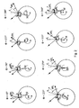
- a measuring light beam illuminates the specimen surface at a defined angle of incidence ⁇ i (cf. Fig. 1 ).
- the light beam reflected by the specimen surface can be registered in a plane S and the deflection X of the reflected light bundle to a calibrated zero position S 0 can be detected and evaluated.
- the zero position of a receiver located in the plane S indicates the reflection angle ⁇ r of an ideally flat surface F 0 lying in the scanning path and its surface normal n 0 correspond to the gradient of the Tastbahn.
- a lateral offset X to the zero position on the position receiver results whenever the local gradient n n of the illuminated real surface profile F r deviates from the Tastbahngradienten. This offset is proportional to the day of the difference angle ⁇ r, n , from which, according to the law of reflection, the local inclination angle d ⁇ n can be calculated.
- the test object surface F r is scanned with a given scanning step dx and the profile of the test object is calculated by integration of the local surface slopes d ⁇ n .
- the local inclination angle of the illuminated surface can be increased by a multiple compared to guideway errors (eg height offset to the tactile path) at a long optical path of the reflected light beam.
- the method is also insensitive to vertical vibrations of the specimen (see, eg DE 3503858 A1 . DE 202004009727 U1 ) and additionally enables the determination of the roughness, if the scattering behavior of the reflected light bundle is measured angularly resolved, eg with a CCD line ( US 4,859,062 ).
- the influence of the eccentricity and vertical vibrations on the profile height determination according to the above-quoted angle measurement method is not critical.
- the first Fourier component introduced by the eccentricity can be filtered out of the height profile, while short-wave vertical oscillation components, due to the short integration intervals, remain almost unnoticed in the measurement result.
- the eccentricity of the sample also leads to distortion of the sampling points in the circumferential direction.
- the resulting influence of the eccentricity on the reflection behavior of the measuring beam during a full rotation of the test object is exemplary in FIG FIG. 2 clarified.
- a cylinder section to be examined for example a shaft, is shown as a circle in several rotational phases, wherein it is rotated with the circle center M about the axis of rotation P.
- the amplitude of the eccentricity results from the distance between P and M.
- the real angle scan on the surface of the device under test varies with eccentricity.
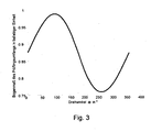
- the profile heights determined by means of differential angle measurement DUT therefore do not result from an equidistant scan of the circumference of the cylinder, but from Tastabofficen which vary sinusoidally by an average value depending on the azimuthal position of the eccentricity, which in FIG. 3 is shown.
- this distortion is critical because it leads to a frequency band extension, which prevents a determination of the real existing main frequency from the Fourier spectrum of the circumferential profile.
- a compact device for distance determination by means of a triangulation method is disclosed in US Pat US 4,596,460 presented.
- a focusing lens images the off-axis beam of the illumination source onto a specimen surface.
- a roof edge prism aligned with the lens is used for beam deflection.
- a roof side of the prism directs the illumination beam path so that the convergent illumination light beam is incident on the specimen surface at a defined angle of incidence.
- the reflected light beam at the specimen surface is received via the same prism and returned to the other side of the roof prism.
- the compact optical concept requires a very precise adjustment of all optical components to each other, which is complicated and prone to failure, especially because of the off-axis beam. A simplification of the adjustment would result if the optical components are combined by means of precise mechanical spacers. However, the production of such components is complicated and expensive.
- a simple compact sensor for optically controlling a surface condition is disclosed in US Pat EP 0 628 787 A2 presented.
- a grazing light beam is reflected and scattered by the specimen surface.
- the intensities of the vertically and parallel polarized light of the directly reflected light beam are detected and set in relation to one another.
- a prism be used, wherein a polarization beam splitter splits the two polarization components and deflects with a mirror layer on another prism surface.
- the beam offset of the two polarization components introduced by the polarization beam splitter plate and mirror layer can be used to place two receivers directly on the prism surface which measure the intensities separately.
- the prism serves as a reference body for defined beam deflection and detection.
- the prism angles, as proposed there, are not suitable for effecting a targeted interference light suppression.
- the prism angles indicate the reference coordinates of the measuring system. For example, a prism surface as a contact surface for a Receiver unit used. Furthermore, parasitic reflections can be minimized or eliminated by optimizing the prism angle.
- this arrangement relates to the measurement of a path difference based on two reflected beams for determining the thickness of optically transparent materials.
- the present invention is therefore based on the object of specifying a method and a device suitable for carrying out the method, which do not have the above-described disadvantages of the prior art, with a small measurement effort and high stability to disturbing environmental influences quickly form deviations and ripples quantitatively detected and be evaluated, the optical state of the surfaces to be examined (highly reflective or rougher surfaces) without effect on the Are method and thus the proposed solution in near-process or in-process can be used advantageously.
- a lighting device illuminates the rotationally symmetrical surface to be examined in a defined angle of incidence ⁇ i in the circumferential direction.
- the center of gravity of the light beam reflected from the surface is determined by means of a position sensitive optoelectronic sensor detected.
- the measuring light bundle reflected at the angle ⁇ r, n is a function of the local surface gradient of the illuminated surface area n deflected.
- the angular difference between the real and the ideal reflection angle ⁇ r, n - ⁇ r (ideally the surface gradient is n 0 perpendicular to the scanning path) is measured on the position-sensitive surface S of the optoelectronic receiver as a path difference X (see. Fig. 1 ).
- This deflection is recorded, for example, at least two closed revolutions of the test specimen with equidistant angular increments about the axis of rotation P.
- the measured position signals X can be converted into reflection angles ⁇ r, n . After the law of reflection ⁇ r .
- n ⁇ j + 2 ⁇ d ⁇ ⁇ , n - ⁇ i .
- ⁇ r, n the local reflection angle and ⁇ i are the angle of incidence of the measuring light beam
- the local surface tilt angle d ⁇ n of the specimen can be determined in the circumferential direction.
- Local errors of the guideway eg concentricity error of educalingsspannvorraum
- ripples due to bearing clearance of the tensioning device and high-frequency oscillations between specimen surface and sensor affect the accuracy of the measured values only slightly, since due to the long "lever arm" of the reflected Meßlichtbündels the measurement signal detects primarily angular changes of the direct reflex.
- the measurement signal d ⁇ r ( ⁇ ) is composed of a short-wave local deviation of the surface gradient n n to the vertical ideal trajectory normal n 0 , which causes the ripple or shape deviation of the real surface profile, and a long-wave deviation of the normal n c too n 0 , which is introduced by the eccentricity (cf to the above Fig. 2 ).
- the long-wave components of the measurement signal d ⁇ e ( ⁇ ) are used directly for the correction.
- the long-wave slope values d ⁇ e are calculated for each rotation angle value ⁇ according to the law of reflection.
- the angular displacement d ⁇ e corresponds exactly to the distortion of the equidistant Winkelabtastung eccentric rotation of a DUT.
- the measured angle differences are thus a function d ⁇ r ( ⁇ + d ⁇ e ).
- Fig. 4 The influence of the eccentricity on an uncorrected and a corrected signal clarifies Fig. 4 .
- a cylinder is assumed which has a waviness of 200 waves per circumference with an amplitude of 500 nm and a shape deviation of three waves per circumference with an amplitude of 5 ⁇ m, which is eccentrically rotated, the displacement between the rotation axis P and the center of the circle M should be one tenth of the cylinder radius.
- Fig. 4a shows the profile deviation of the cylinder from the ideal circular shape in a coated representation.
- the resulting angular displacement of a measurement beam for equidistant angular scanning about P is in Fig. 4b shown.
- the non-contact optical angle measurement on cylindrical samples enables high measuring speeds, it is advantageous to carry out the measurement for several revolutions. If a uniform rotational movement can be assumed, an equidistant angle scanning without precise angle tables is possible.
- an external clocking eg a rectangular pulse generator
- the angular value of the rotating DUT is sampled at a fixed frequency.
- a position-sensitive photodiode PSD is used as the position-sensitive receiver, as is preferred in the context of this invention, two locally typical signals are obtained. The sum signal of the PSD detects the total intensity of the light reflected from the specimen and thus the local reflection coefficient.
- the difference signal of the PSD characterizes the local angular excursion of the direct reflex and thus the local inclination angle of the real profile.
- Both signals are suitable for correlation analysis to determine the number of tactile points of a full revolution and thus the angular increment of the measurement.
- both signals it is possible for both rough and highly reflective surfaces to perform precise profile determinations in the circumferential direction with external clocking for multiple revolutions.
- the method is well suited for in-process measurement during machining of rotationally symmetric parts.
- the systematically occurring rotation angle-dependent signals can be identified as periodic functions and can be separated from all random measurement errors by means of signal filtering.
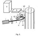
- FIG. 5 schematically illustrates the basic structure of a device designed for this purpose, will be explained.
- a laser diode 1 emits a light beam 3, which is focused with the aid of an optical system 2 onto a test object surface 5 which can be displaced in rotational movements.
- a cylindrical lens is favorably chosen for the measurement of rough surfaces, since, due to the line illumination in the case of small line widths in the circumferential direction, it is possible to average over the speckle structure of the reflected light bundle 6 with the aid of the receiver surface of a position-sensitive optoelectronic receiver 7. This leads to an improved focus determination of the reflected light bundle 6 with coherent noise of the bundle and thus enables a differential angle measurement on rough cylindrical scholarlingsobervid.
- the central optical component of the claimed device is a prism 4 arranged in the beam path, which deflects both the incident light beam 3 and the light beam 6 reflected by the specimen surface.
- a prism 4 arranged in the beam path, which deflects both the incident light beam 3 and the light beam 6 reflected by the specimen surface.
- the adjustment process of the optics is simplified, since the prism 4 can serve as an angle reference system.
- the prism surfaces which include precise prism angles, are reference surfaces for an optoelectronic receiver 7 and the illumination optics with laser diode 1 and focus optics 2.
- the prism surface onto which the reflected light beam 6 passes is selected within the scope of the invention as a direct contact surface for the receiver 7.
- the direct reflection at the first refracting prism surface in the incident beam path can be used for adjustment and accurate Alignment of the optical axis of the lighting system can be used.
- the test object 5 rotates with a known angular increment or uniformly, as described in more detail in the method, about a rotation axis P which should lie in the vicinity of the cross-section center M of the test object 5 and is aligned parallel to the test object axis.
- the readout of the optoelectronic receiver 7 takes place via a measurement data acquisition unit 8, which amplifies, digitizes and stores the measured values.
- the measurement data acquisition unit 8 further realizes the synchronization of the measured value recording with the rotation of the test object.
- the synchronization can be carried out with uniform rotational movement of the specimen via an external or internal clock or at defined Winkei suits ein the specimen via a direct control of the data acquisition unit 8 by signals of a conventional motor controller from the rotary motor of educalingsrea.
- the measurement data are transmitted to an evaluation unit 9, which performs the calculation of ripple and shape deviation parameters in a manner described later, displays these parameters, logged and optionally compared with tolerance specifications and for control of an automatic quality control process forwards to a control unit.
- the assignment of the measured values to equidistant angular increments with uniform test specimen rotation takes place via the correlation analysis of the measurement signals described in accordance with the invention for at least two revolutions of the test specimen. Occurring eccentricities in theticiansrotation be compensated by the inventive method and in the last step, the measured difference angle converted into profile heights from which the evaluation unit 9 calculates the necessary ripple and shape deviation parameters.
- a gear shaft with a diameter of 44.7mm is quasi centric taken in the example with the help of a three-jaw chuck and set by rotation of the three-jaw chuck through a turntable in a uniform rotation.
- the optical measuring head according to the invention is delivered radially to the rotating shaft until the measuring head has reached the optimum operating point. This position can be approached automatically by detecting the signals of the receiver unit, since at the optimum working distance of the measuring head, the light reflected on the striglingswelle light illuminates the receiver 7 in the zero position.
- the total intensity of the light incident on the receiver (hereinafter referred to as the sum signal) is high, and the center of gravity of the reflected light beam 6 illuminates the receiver surface in the center so that the position-dependent signal of the PSD is zero (hereinafter referred to as differential signal). If the optimum working distance of the measuring head to the test piece surface is set, the measured value is recorded.
- a measurement clock is activated, which detects the measurement signals at a fixed frequency and a storage unit 8 feeds.
- the measurement clock generator is, for example, an external square-wave generator that controls the acquisition of measured values via the trigger input of a PC measurement card.
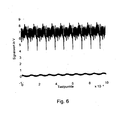
- FIG. 6 shows the measured signals of the PSD thus recorded for a uniformly rotating gear shaft with a diameter of 44.7 mm.
- the sampling frequency was 50kHz.
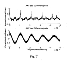
- FIG. 7 show the Autocorrelation functions of the waveforms FIG. 6 .
- the autocorrelation coefficient is a measure of the self-similarity of a function in its lateral displacement. The coefficient reaches a maximum when the gradients of the shifted and unshifted function become virtually congruent, which is achieved when shifting by one revolution. This maximum repeats periodically at each additional completed rotation position. For the example shown, this results in a Tast Vietnameseress per admirlingsumfitung of 10691. Since the transmission shaft has a ripple, the autocorrelation function of the difference signal is superimposed by a short-wave periodic function, but also has significant maxima at the positions of the completed revolutions.
- the maximums of the autocorrelation functions are determined and from whose positions the number of scanning points per test piece revolution is calculated.
- the lower limit frequency of the measuring signal is defined by the number of revolutions. If several revolutions have been measured, all longer-term components in the signal are due to measurement errors.
- these interference signals can be removed from both the sum and the difference signal. In order to suppress measurement errors whose frequency components are in the frequency band of the measurement signals, further filtering is performed after the high-pass filtering of the signals.
- the sum and the difference signal are split into signal sections whose respective lengths correspond exactly to one test piece rotation. These signal sections are Fourier-transformed and the absolute parts of the Fourier components are calculated. For both the sum and difference signals, it is thus possible to generate as many Fourier functions as revolutions were measured.
- the Fourier components of the actual measurement signal must be contained in all Fourier functions of the individual revolutions.
- the Fourier components with the smallest amplitude amount contained in all subfunctions are now to be added a Fourier réelle composed and generated from this by back transformation of the filtered waveform.
- the intensity-independent deflection signal can be converted directly into a reflection angle signal d ⁇ r ( ⁇ ) and the local surface tilt angle d ⁇ n can be determined according to the known reflection equation.
- FIG. 8 shows in the upper diagram the tilt angle signal calculated from the calibration data of the measurement Fig. 6 and 7 , The eccentricity of the measurement is included in the waveform.
- the eccentric tilt angle shift can be determined (cf. Fig. 8 lower picture). This corresponds exactly to the sampling point distortion according to the invention with eccentric rotation of a test object.
- the measurement signal d ⁇ n must be interpolated.
- the surface sampling of the specimen realized during the measurement was carried out at the angle values ⁇ + d ⁇ e ( ⁇ ), wherein the rotational angle values for ⁇ are in the interval 0 ° to 360 ° with angular increments of 360 ° / (measuring point number per revolution) (in the illustrated example the theoretical angular increment is 0.0337 °).
- the measured values for an equidistant scan with the fixed angular increment of 360 ° / are determined.
- the influence of the eccentricity on the measurement signal is low.
- the maximum eccentric angular displacement d ⁇ e is slightly more than the measuring step size and thus leads to maximum step size distortions of approximately one angular step.
- the equalization of the signal values thus imperceptibly alters the signal behavior.
- the measured signal is composed of the local inclination angle difference (the actual measured variable) and the increasing spatial displacement due to the path deviation.
- a locus calculation based solely on the integration of tilt angles can not be used to determine the runout.
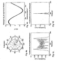
- FIG. 9 shows the influence of the measuring beam incidence angle on the phase and the amplitude of the eccentric inclination angle shift. If the specimen surface is illuminated vertically (dashed curve), d ⁇ e results exclusively on the inclination angle shift of the illumination location. The additional Tastbahnabweichung leads only to a life extension of the measurement signal, but causes no deflection of the reflected light beam on the position-sensitive receiver. With a known test specimen diameter D and a known number of angular steps per revolution N, which were obtained from the autocorrelation function or are known at an angle step adjustment, can be according to the equation z e .
- the maximum of z e , n indicates the concentricity error, which in the example chosen Fig. 9 17.4 ⁇ m. If the same test object is illuminated at an angle of incidence of 40 °, the angle difference measurement results in an increased measurement signal (cf. Fig. 9 , solid line). In addition, the maximum relative to the vertically illuminated measurement is exactly shifted by the angle of incidence.
- the measured curve is normalized to the ratio d ⁇ e ( ⁇ max - ⁇ i ) / d ⁇ e ( ⁇ max ), so that one obtains a damped curve whose maximum now carries the value d ⁇ e ( ⁇ max - ⁇ i ). From this curve, as described above, the profile heights z e, n can be calculated from which the concentricity error can be determined as shown. This approximation leads to good results in the determination of concentricity errors. With eccentricities of less than 10% relative to the radius of the test object, the maximum deviations for the concentricity error determination are less than 2% according to the above-described approximation method.
- the shape deviation and ripple analysis is largely based on the standardized procedure for Tastschnitttownen.
- the angular displacement d ⁇ e introduced by the eccentricity is added to the measurement signal d ⁇ n and interpolated.
- the thus corrected measured values d ⁇ n now relate exclusively to the local inclination angle differences of the specimen surface.
- d ⁇ j stands for the corrected profile slope value (freed from the influence of the eccentricity).
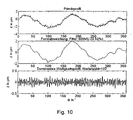
- the form deviation and the dominant waviness profiles from the profile z n can now be determined by known filter methods.
- the curve of z n corresponds to the primary profile (cf. Fig. 10 , top picture).
- a standardized low-pass filter here for example a Gaussian low pass with the cutoff wavelength of 50 waves per circumference
- the shape deviation according to VDA2007 the W profile
- the zero bandpass described in VDA2007 is used to generate the dominant ripple profiles.
- the dominant ripple profile is given at a wave number of 107 waves per revolution and in the bottom picture of Fig. 10 shown.
- the method and the device can be used for a large diameter range of about 1 mm to 2 m of rotationally symmetric test specimens.
- the only prerequisite is that the local surface slopes of the test object are small enough to be able to detect the reflected measuring light bundle in the predetermined measuring angle range of the measuring device.
- a prism with an edge length of 25 mm and a position-sensitive receiver (PSD) chosen and arranged according to the above specifications were sufficient. All of the above-mentioned calculations are realized by correspondingly provided numerical algorithms by means of corresponding PC programs in the evaluation unit 9.
Abstract
Description
Die Erfindung betrifft ein Verfahren und eine Vorrichtung zur Bestimmung und Vermessung von Formabweichungen und Welligkeiten an rotationssymmetrischen technischen Oberflächen in Umfangsrichtung, die mit geringem Messaufwand und hoher Stabilität gegenüber störenden Umwelteinflüssen schnell Formabweichungen und Welligkeiten quantitativ erfassen und bewerten.The invention relates to a method and a device for determining and measuring deviations in shape and ripples on rotationally symmetrical technical surfaces in the circumferential direction, which quickly detect and evaluate deviations in form and waviness with little effort and high stability against disturbing environmental influences.
Rotationssymmetrische Flächen (z.B. beim Zylinder oder der Kugel) werden technisch zumeist als statische oder dynamische Dichtflächen oder als Gleit- oder Rollflächen eingesetzt. Gestaltabweichungen 1. und 2. Ordnung (Formabweichung und Welligkeit) wirken sich somit besonders nachteilig auf das funktionale Verhalten dieser Flächen aus. Folglich gelten für rotationssymmetrische Werkstücke besonders hohe Qualitätskriterien bezüglich Formabweichung und Welligkeit.Rotationally symmetric surfaces (for example in the case of the cylinder or the ball) are technically mostly used as static or dynamic sealing surfaces or as sliding or rolling surfaces. Shape deviations 1st and 2nd order (shape deviation and waviness) thus have a particularly detrimental effect on the functional behavior of these surfaces. Consequently, particularly high quality criteria with regard to shape deviation and waviness apply to rotationally symmetrical workpieces.
Formabweichungen bei spanenden Bearbeitungsverfahren resultieren zumeist aus der elastischen Verformung der Bearbeitungseinheit (Werkzeug, Werkzeughalter etc.), der elastischen Verformung des Werkstücks oder Führungsbahnfehlern des Werkzeugs oder Werkstücks während der Bearbeitung. Welligkeiten werden hervorgerufen durch Schwingungen des Werkzeugs oder Werkstücks beim Spanabtrag. Der Einfluss dieser Störgrößen auf die Gestaltabweichungen 1. und 2. Ordnung hängt in komplexer Weise von einer Reihe technologischer Parameter des Bearbeitungsprozesses ab (z.B. den Schnittbedingungen beim Spanabtrag, dem Werkstückmaterial, usw.). Um die Oberflächenfunktion des bearbeiteten Werkstücks zu bewerten und eine Analyse des Bearbeitungsprozesses zu ermöglichen, ist eine schnelle Messung dieser Gestaltabweichungen wünschenswert.Form deviations in machining processes result mostly from the elastic deformation of the processing unit (tool, tool holder, etc.), the elastic deformation of the workpiece or guideway errors of the tool or workpiece during processing. Ripples are caused by vibrations of the tool or workpiece during chip removal. The influence of these disturbances on the shape deviations 1st and 2nd order depends in a complex way on a number of technological parameters of the machining process (eg the cutting conditions during chip removal, the workpiece material, etc.). In order to evaluate the surface function of the machined workpiece and to allow an analysis of the machining process, a quick measurement of these shape deviations is desirable.
Formabweichungen sowie Welligkeiten rotationssymmetrischer Flächen werden nach dem Stand der Technik vorrangig mit Hilfe von taktilen Formprüfgeräten gemessen. Unter Laborbedingungen erlauben es diese Tastschnittverfahren, Gestaltabweichungen mit hoher Präzision zu erfassen. Jedoch benötigen diese Messgeräte eine aufwendige Justage des Prüflings sowie hohe Messzeiten.Shape deviations and ripples of rotationally symmetrical surfaces are measured according to the prior art primarily with the aid of tactile Formprüfgeräten. Under laboratory conditions, these stylus methods allow to detect deviations in shape with high precision. However, these measuring devices require a complex adjustment of the test specimen and high measuring times.
Als schnelle optische Messverfahren zur Erfassung von Oberflächenprofilen rotationssymmetrischer Prüflinge sind weiterhin Autofokus-Verfahren und Triangulationsverfahren bekannt.As a fast optical measurement method for detecting surface profiles of rotationally symmetric specimens are still known autofocus method and triangulation.
Autofokus-Verfahren und Triangulationsverfahren messen punktweise Höhendifferenzen in Bezug zu einer idealen Tastbahn. Beim Triangulationsverfahren wird das vertikale Auflösungsvermögen wesentlich vom Einfallswinkel des Messlichtbündels und dem Abbildungsmaßstab des Messobjektivs bestimmt. Wird beim Triangulationsverfahren ausschließlich das gestreute Licht des Prüflings als Messsignal verwandt (z.B.
Autofokussensoren messen die Höhe eines beleuchteten Oberflächenpunktes zu einer Bezugsbahn mit hoher vertikaler Auflösung bei gleichzeitig großem Messbereich (vgl. z.B.
Verfahren, bei denen Führungsbahnfehler während der Profilabtastung die Messergebnisse kaum beeinflussen, sind Winkelmessverfahren. Ein Messlichtbündel beleuchtet die Prüflingsoberfläche unter einem definierten Einfallswinkel Θi (vgl.
Bei der Rundheitsmessung mittels eines Drehtischs zum Bestimmen des Oberflächenprofils eines zylindrischen Prüflings in Umfangsrichtung ist der Einfluss der Exzentrizität sowie vertikaler Schwingungen auf die Profilhöhenbestimmung nach dem vorstehend zitierten Winkelmessverfahren unkritisch. Mit Hilfe einer Hochpassfilterung (
Mit Hilfe von Multisensorik (vgl. z.B.
Weiterhin sind Vorrichtungen, die sich anderer Messverfahren bedienen, aus dem Stand der Technik bekannt, nämlich:Furthermore, devices which use other measuring methods are known from the prior art, namely:
Eine kompakte Vorrichtung zur Abstandsbestimmung mit Hilfe eines Triangulationsverfahrens wird in
Ein einfacher kompakter Sensor zur optischen Kontrolle eines Oberflächenzustands wird in
In einer anderen Anwendung (vgl.
Um ein Verfahren zur Welligkeits- und Formabweichungsbestimmung fertigungsnah einsetzen zu können, muss es als einfache robuste Vorrichtung konzipiert und aufgebaut werden.In order to be able to use a method for determining ripple and shape deviation close to production, it must be designed and constructed as a simple, robust device.
Vorliegender Erfindung liegt somit die Aufgabe zugrunde, ein Verfahren und eine zur Durchführung des Verfahrens geeignete Vorrichtung anzugeben, die vorstehend beschriebene Nachteile des Standes der Technik nicht aufweisen, wobei mit einem geringen Messaufwand und hoher Stabilität gegenüber störenden Umwelteinflüssen schnell Formabweichungen und Welligkeiten quantitativ erfass- und bewertbar sein sollen, der optische Zustand der zu untersuchenden Oberflächen (hochreflektierende oder rauere Oberflächen) ohne Einfluss auf das Verfahren sind und somit die vorgeschlagene Lösung im near-process- oder in-process vorteilhaft einsetzbar ist.The present invention is therefore based on the object of specifying a method and a device suitable for carrying out the method, which do not have the above-described disadvantages of the prior art, with a small measurement effort and high stability to disturbing environmental influences quickly form deviations and ripples quantitatively detected and be evaluated, the optical state of the surfaces to be examined (highly reflective or rougher surfaces) without effect on the Are method and thus the proposed solution in near-process or in-process can be used advantageously.
Ausgehend von bekannten Verfahren zur Bestimmung von Formabweichungen und Welligkeiten von rotationssymmetrischen Teilen, bei dem ein Messlichtstrahl unter einem vorgebbaren Winkel in Umfangsrichtung des Prüfteils eingestrahlt und der reflektierte Messlichtstrahl bei Drehung des Prüfteils um eine Achse senkrecht zur Umfangsrichtung detektiert wird, wird die Aufgabe vorliegender Erfindung durch den Gegenstand des Anspruchs 1.Starting from known methods for determining deviations in form and ripples of rotationally symmetrical parts, in which a measuring light beam is irradiated at a predeterminable angle in the circumferential direction of the test piece and the reflected measuring light beam is detected upon rotation of the test part about an axis perpendicular to the circumferential direction, the object of the present invention by the subject matter of
Zum leichteren Verständnis der Erfindung soll nachstehende allgemeine Beschreibung dienen:For a better understanding of the invention, the following general description is intended to serve:
Eine Beleuchtungseinrichtung beleuchtet die zu untersuchende rotationssymmetrische Oberfläche in einem definierten Einfallswinkel Θi in Umfangsrichtung. Der Schwerpunkt des von der Oberfläche reflektierten Lichtbündels wird mit Hilfe eines positionsempfindlichen optoelektronischen Sensors detektiert. Bei Rotation des Prüflings um eine Achse P, deren Zentrum in der Nähe des Querschnittmittelpunktes M liegt und quasi parallel zur Prüflingsachse verläuft, wird das unter dem Winkel Θr,n reflektierte Messlichtbündel in Abhängigkeit vom lokalen Oberflächengradienten des beleuchteten Oberflächengebiets ![]()
wobei Θr,n der lokale Reflexionswinkel und Θi der Einfallswinkel des Messlichtbündels sind, lassen sich die lokalen Oberflächenneigungswinkel dφn des Prüflings in Umfangsrichtung bestimmen. Lokale Fehler der Führungsbahn (z.B. Rundlauffehler der Prüflingsspannvorrichtung), Welligkeiten durch Lagerspiel der Spannvorrichtung sowie hochfrequente Schwingungen zwischen Prüflingsoberfläche und Sensor beeinträchtigen die Genauigkeit der Messwerte nur geringfügig, da infolge des langen "Hebelarms" des reflektierten Messlichtbündels das Messsignal vorrangig Winkeländerungen des direkten Reflexes erfasst. Jedoch führen langwellige Bahnabweichungen, wie z.B. die durch die Exzentrizität verursachte, zu langwelligen Verschiebungen des Beleuchtungspunktes A und damit zu einer ungleichmäßigen Abtastung des Prüflingsumfangs. Liegt der Querschnittsmittelpunkt M des Prüflings nicht auf der Drehachse P, verursacht die Krümmung der zylindrischen Prüflingsoberfläche eine Drehung dφe des Oberflächengradienten ![]()
![]()
where Θ r, n the local reflection angle and Θ i are the angle of incidence of the measuring light beam, the local surface tilt angle dφ n of the specimen can be determined in the circumferential direction. Local errors of the guideway (eg concentricity error of Prüflingsspannvorrichtung), ripples due to bearing clearance of the tensioning device and high-frequency oscillations between specimen surface and sensor affect the accuracy of the measured values only slightly, since due to the long "lever arm" of the reflected Meßlichtbündels the measurement signal detects primarily angular changes of the direct reflex. However, long-wave path deviations, such as caused by the eccentricity, lead to long-wave shifts of the illumination point A and thus to an uneven sampling of the specimen circumference. If the cross-section center M of the test object is not on the rotation axis P, the curvature of the cylindrical test surface causes a rotation dφ e of the surface gradient ![]()
Das Messsignal dΘr(Φ) setzt sich zusammen aus einer kurzwelligen lokalen Abweichung des Oberflächengradienten
Um die Fehlereinflüsse der Exzentrizität auf die lokale Profilneigungsbestimmung zu minimieren, werden die langwelligen Anteile des Messsignals dΘe(Φ) direkt zur Korrektur genutzt. Mit Hilfe des tiefpassgefilterten Messsignals werden nach dem Reflexionsgesetz die langwelligen Neigungswerte dφe für jeden Rotationswinkelwert Φ berechnet. Die Winkelverschiebung dφe entspricht exakt der Verzerrung der äquidistanten Winkelabtastung bei exzentrischer Rotation eines Prüflings. Die gemessenen Winkeldifferenzen sind somit eine Funktion dΘr(Φ+dφe). Mit Hilfe einer Interpolation der Messwerte mit einer äquidistanten Winkelteilung kann somit der Einfluss der Exzentrizität ohne Zusatzinformation erfindungsgemäß kompensiert werden. Den Einfluss der Exzentrizität auf ein unkorrigiertes und ein korrigiertes Signal verdeutlicht
Da die berührungslose optische Winkelmessung an zylindrischen Proben hohe Messgeschwindigkeiten ermöglicht, ist es vorteilhaft, für mehrere Umdrehungen die Messung durchzuführen. Kann dabei eine gleichförmige Drehbewegung angenommen werden, ist eine äquidistante Winkelabtastung ohne präzise Winkeistelltische möglich. Mit Hilfe einer externen Taktung (z.B. einem Rechteckimpulsgenerator) wird der Winkelwert des rotierenden Prüflings mit fester Frequenz abgetastet. Wird als positionsempfindlicher Empfänger z.B. eine positionsempfindliche Fotodiode PSD eingesetzt, wie dies im Rahmen dieser Erfindung bevorzugt erfolgt, erhält man zwei ortstypische Signale. Das Summensignal der PSD erfasst die Gesamtintensität des vom Prüfling reflektierten Lichts und somit den lokalen Reflexionskoeffizienten. Das Differenzsignal der PSD kennzeichnet die lokale Winkelauslenkung des direkten Reflexes und somit den lokalen Neigungswinkel des realen Profils. Beide Signale eignen sich zur Korrelationsanalyse, um die Tastpunktanzahl einer vollen Umdrehung zu ermitteln und damit die Winkelschrittweite der Messung. Mit Hilfe beider Signale ist es sowohl für raue als auch für hoch reflektierende Oberflächen möglich, bei mehrfacher Umdrehung präzise Profilbestimmungen in Umfangsrichtung mit externer Taktung durchzuführen. Selbst im praktisch fast auszuschließenden Fall ideal reflektierender Zylinder lassen sich solche, durch Einbringung einer künstlichen Exzentrizität, nach dem vorgeschlagenen Verfahren vermessen, wobei die Exzentrizität nach der erfindungsgemäßen Vorschrift bei der Datenanalyse korrigierbar ist. Somit eignet sich das Verfahren gut für die In-process-Messung bei spanender Bearbeitung von rotationssymmetrischen Teilen. Infolge der schnellen Messung mehrerer Prüflingsumdrehungen sind die systematisch auftretenden rotationswinkelabhängigen Signale als periodische Funktionen identifizierbar und lassen sich durch eine Signalfilterung von allen zufälligen Messfehlern trennen.Since the non-contact optical angle measurement on cylindrical samples enables high measuring speeds, it is advantageous to carry out the measurement for several revolutions. If a uniform rotational movement can be assumed, an equidistant angle scanning without precise angle tables is possible. By means of an external clocking (eg a rectangular pulse generator), the angular value of the rotating DUT is sampled at a fixed frequency. If, for example, a position-sensitive photodiode PSD is used as the position-sensitive receiver, as is preferred in the context of this invention, two locally typical signals are obtained. The sum signal of the PSD detects the total intensity of the light reflected from the specimen and thus the local reflection coefficient. The difference signal of the PSD characterizes the local angular excursion of the direct reflex and thus the local inclination angle of the real profile. Both signals are suitable for correlation analysis to determine the number of tactile points of a full revolution and thus the angular increment of the measurement. With the help of both signals, it is possible for both rough and highly reflective surfaces to perform precise profile determinations in the circumferential direction with external clocking for multiple revolutions. Even in the case of ideally reflecting cylinders, which are virtually almost impossible to exclude, they can be measured by introducing an artificial eccentricity according to the proposed method, wherein the eccentricity can be corrected according to the method of the invention in the data analysis. Thus, the method is well suited for in-process measurement during machining of rotationally symmetric parts. As a result of the rapid measurement of several test specimen revolutions, the systematically occurring rotation angle-dependent signals can be identified as periodic functions and can be separated from all random measurement errors by means of signal filtering.
Die Erfindung soll nachstehend anhand von Ausführungsbeispielen und schematischer Zeichnungen näher erläutert werden. Es zeigen:
- Fig. 1
- schematisch das Prinzip von Differenzwinkelmessungen,
- Fig. 2
- eine schematische Darstellung des Einflusses einer exzentrischen Rotation eines zylindrischen Prüflings bei einer Winkeldifferenzmessung,
- Fig. 3
- eine beispielhaft erhaltenen Kurve einer Umfangsabtastung eines zylindrischen Prüflings bei exzentrischer Rotation,
- Fig. 4a
- eine mikrogeometrische Profilfunktion eines Zylinders,
- Fig. 4b
- ein normiertes Reflexionssignal (Differenzwinkelkurve) bei exzentrischer Rotation,
- Fig. 4c
- beispielhaft die Fourierkomponeten einer unkorrigierten Differenzwinkelkurve,
- Fig. 4d
- die Fourierkomponeten einer erfindungsgemäß korrigierten Differenzwinkelkurve,
- Fig. 5
- schematisch einen prinzipiellen Aufbau einer erfindungsgemäßen Vorrichtung,
- Fig. 6
- beispielhafte Messsignale einer PSD für eine gleichförmig rotierende Getriebewelle, wobei die obere Kurve das Summensignal und untere Kurve das Differenzsignal der PSD darstellt,
- Fig. 7
- zeigt die Autokorrelationsfunktionen der Signalverläufe aus
Figur 6 , - Fig. 8
- zeigt im oberen Diagramm das anhand der Kalibrierdaten berechnete Neigungswinkelsignal der Messung nach
Fig. 6 und7 und im unteren Diagramm die exzentrische Neigungswinkelverschiebung nach einer Tiefpassfilterung mit einem Gaußfilter, - Fig. 9
- zeigt den Einfluss des Messlichtbündeleinfallswinkels auf die Phase und die Amplitude der exzentrischen Neigungswinkelverschiebung und
- Fig. 10
- Kurven für das Primärprofil, die Formabweichung und ein dominantes Welligkeitsprofil anhand eines Beispiels.
- Fig. 1
- schematically the principle of differential angle measurements,
- Fig. 2
- a schematic representation of the influence of an eccentric rotation of a cylindrical specimen in an angle difference measurement,
- Fig. 3
- an example obtained curve of a circumferential scan of a cylindrical specimen in eccentric rotation,
- Fig. 4a
- a microgeometric profile function of a cylinder,
- Fig. 4b
- a normalized reflection signal (differential angle curve) with eccentric rotation,
- Fig. 4c
- for example, the Fourierkomponeten an uncorrected di f ference angle curve,
- Fig. 4d
- the Fourier components of an inventively corrected differential angle curve,
- Fig. 5
- schematically a basic structure of a device according to the invention,
- Fig. 6
- Exemplary measurement signals of a PSD for a uniformly rotating transmission shaft, wherein the upper curve represents the sum signal and the lower curve represents the difference signal of the PSD,
- Fig. 7
- shows the autocorrelation functions of the waveforms
FIG. 6 . - Fig. 8
- shows in the upper diagram the tilt angle signal calculated from the calibration data of the measurement
Fig. 6 and7 and in the lower diagram the eccentric tilt angle shift after a low-pass filtering with a Gaussian filter, - Fig. 9
- shows the influence of the measuring beam incidence angle on the phase and the amplitude of the eccentric inclination angle shift and
- Fig. 10
- Curves for the primary profile, the shape deviation and a dominant waviness profile using an example.
Zum leichteren Verständnis des erfindungsgemäßen Verfahrens und der dafür erforderlichen Signalgewinnung soll zunächst anhand von
Eine Laserdiode 1 emittiert ein Lichtbündel 3, das mit Hilfe einer Optik 2 auf eine in Drehbewegungen versetzbare Prüflingsoberfläche 5 fokussiert wird. Für die Fokussieroptik ist für die Vermessung rauer Oberflächen günstigerweise eine Zylinderlinse gewählt, da infolge der Linienbeleuchtung bei kleinen Linienbreiten in Umfangsrichtung über die Specklestruktur des reflektierten Lichtbündels 6 mit Hilfe der Empfängerfläche eines positionsempfindlichen optoelektronischen Empfängers 7 gemittelt werden kann. Dies führt zu einer verbesserten Schwerpunktbestimmung des reflektierten Lichtbündels 6 bei kohärentem Rauschen des Bündels und ermöglicht somit eine Differenzwinkelmessung an rauen zylindrischen Prüflingsoberflächen. Zentrales optisches Bauteil der beanspruchten Vorrichtung ist ein im Strahlengang angeordnete Prisma 4, das sowohl das einfallende Lichtbündel 3 als auch das von der Prüflingsoberfläche reflektierte Lichtbündel 6 umlenkt. Infolge dieser Winkeltransformation kann eine kompakte Bauweise des Sensorkopfs erreicht werden bei gleichzeitig großem Messbereich eines im Rahmen des Verfahrens zu ermittelnden Differenzwinkels. Der Justiervorgang der Optik vereinfacht sich, da das Prisma 4 als Winkelbezugssystem dienen kann. Die Prismenflächen, die präzise Prismenwinkel einschließen, sind Bezugsflächen für einen optoelektronischen Empfänger 7 und die Beleuchtungsoptik mit Laserdiode 1 und Fokusoptik 2. Die Prismenfläche, auf die das reflektierte Lichtbündel 6 gelangt, wird im Rahmen der Erfindung als direkte Anlagefläche für den Empfänger 7 gewählt. Bei der Beleuchtungsoptik kann der direkte Reflex an der ersten brechenden Prismenfläche im einfallenden Strahlengang zur Justage und genauen
Ausrichtung der optischen Achse des Beleuchtungssystems genutzt werden. Somit ergeben sich präzise Einstellungsmöglichkeiten der Winkel für das einfallende und reflektierte Lichtbündel, die über das Prisma einem festen Bezugssystem zugeordnet sind. Unter Ausnutzung der Totalreflexion an der Auflagefläche zwischen Prisma 4 und Empfänger 7 ist der Sehwinkel des Empfängers eingegrenzt, was sich vorteilhaft zur zusätzlichen Unterdrückung von Störlicht aus der Umgebung auswirkt. Bei der Messwertaufnahme rotiert der Prüfling 5 mit einer bekannten Winkelschrittweite oder gleichförmig, wie im Verfahren detaillierter beschrieben, um eine Rotationsachse P, die in der Nähe des Querschnittmittelpunkts M des Prüflings 5 liegen sollte und parallel zur Prüflingsachse ausgerichtet ist. Bei jedem Rotationswinkelwert erfolgt die Auslesung des optoelektronischen Empfängers 7 über eine Messdatenerfassungseinheit 8, die die Messwerte verstärkt, digitalisiert und speichert. Die Messdatenerfassungseinheit 8 realisiert weiterhin die Synchronisation der Messwertaufnahme mit der Rotation des Prüflings. Die Synchronisation kann bei gleichförmiger Drehbewegung des Prüflings über einen externen oder internen Taktgeber erfolgen oder bei definierter Winkeischrittstellung des Prüflings über eine direkte Ansteuerung der Datenerfassungseinheit 8 durch Signale eines üblichen Motorcontrollers vom Drehmotor der Prüflingsaufnahme. Zur Auswertung der Messung werden die Messdaten an eine Auswerteinheit 9 übertragen, die die Berechnung von Welligkeits- und Formabweichungsparametem in später beschriebener Weise durchführt, diese Parameter anzeigt, protokolliert und gegebenenfalls mit Toleranzvorgaben vergleicht und zur Steuerung eines automatischen Qualitätskontrollprozesses an eine Steuereinheit weiterleitet. Dazu erfolgt die Zuordnung der Messwerte zu äquidistanten Winkelschrittweiten bei gleichförmiger Prüflingsrotation über die erfindungsgemäß beschriebene Korrelationsanalyse der Messsignale bei mindestens zwei Umdrehungen des Prüflings. Auftretende Exzentrizitäten bei der Prüflingsrotation werden durch das erfindungsgemäße Verfahren kompensiert und im letzten Schritt die gemessenen Differenzwinkel in Profilhöhen umgerechnet, aus denen die Auswerteeinheit 9 die notwendigen Welligkeits- und Formabweichungsparameter berechnet.A
Alignment of the optical axis of the lighting system can be used. This results in precise adjustment options of the angle for the incident and reflected light beam, which are assigned via the prism a fixed reference system. Taking advantage of the total reflection at the bearing surface between
Das Verfahren wird im Folgenden anhand eines konkreten Ausführungsbeispiels näher beschrieben. Eine Getriebewelle mit einem Durchmesser von 44,7mm wird im Beispiel mit Hilfe eines Dreibackenfutters quasi zentrisch gefasst und durch Rotation des Dreibackenfutters durch einen Drehtisch in eine gleichförmige Rotation versetzt. Der erfindungsgemäße optische Messkopf wird radial zur rotierenden Welle zugestellt, bis der Messkopf den optimalen Arbeitspunkt erreicht hat. Diese Position kann durch Erfassung der Signale der Empfängereinheit automatisch angefahren werden, da beim optimalen Arbeitsabstand des Messkopfes das an der Prüflingswelle reflektierte Licht den Empfänger 7 in der Nullposition beleuchtet. Somit ist die Gesamtintensität des auf den Empfänger fallenden Lichts (im folgenden mit Summensignal bezeichnet) hoch und der Schwerpunkt des reflektierten Lichtbündels 6 beleuchtet die Empfängerfläche im Zentrum, so dass das positionsabhängige Signal der PSD Null ist (im folgenden mit Differenzsignal bezeichnet). Ist der optimale Arbeitsabstand des Messkopfs zur Prüflingsoberfläche eingestellt, erfolgt die Messwertaufnahme. Ein Messtaktgeber wird aktiviert, der die Messsignale mit fester Frequenz erfasst und einer Speichereinheit 8 zuführt. Der Messtaktgeber ist z.B. ein externer Rechteckgenerator, der über den Triggereingang einer PC-Messkarte die Messwertaufnahme steuert. Für jeden Messpunkt wird die Intensität des reflektierten Lichtbündels sowie die Auslenkung zur Nullposition erfasst, mit Hilfe eines AD-Wandlers digitalisiert und im Puffer eines PC's 9 gespeichert.
Autokorrelationsfunktion der beiden Signale, kann man die Anzahl der Messpunkte pro Prüflingsumdrehung ermitteln.
Autokorrelationsfunktionen der Signalverläufe aus
einer Fourierreihe zusammengestellt und aus dieser durch Rücktransformation der gefilterte Signalverlauf generiert. Durch Normierung (d.h. Quotientenbildung aus Differenzsignal/Summensignal) der gefilterten Differenzsignale auf die gefilterten Summensignale erhält man die intensitätsunabhängigen Auslenkungssignale, die proportional zur lokalen Winkelauslenkung des reflektierten Lichtbündels sind. Anhand der Kalibrierdaten für den Prismenkopf können das intensitätsunabhängige Auslenkungssignal direkt in ein Reflexionswinkelsignal dΘr(Φ) umgerechnet und nach der bekannten Reflexionsgleichung die lokalen Oberflächenneigungswinkel dφn ermittelt werden.
Autocorrelation functions of the waveforms
a Fourierreihe composed and generated from this by back transformation of the filtered waveform. By normalization (ie quotient of differential signal / sum signal) of the filtered differential signals to the filtered sum signals to obtain the intensity-independent displacement signals that are proportional to the local angular deflection of the reflected light beam. Based on the calibration data for the prism head, the intensity-independent deflection signal can be converted directly into a reflection angle signal dΘ r (Φ) and the local surface tilt angle dφ n can be determined according to the known reflection equation.
Eine gute, viel praktikablere Näherung für die Rundlauffehlerermittlung ist jedoch die nachstehend beschriebene. 
die Profilhöhen ze,n ermitteln, die den Tastbahnabstand für jeden Tastpunkt beschreiben. Das Maximum von ze,n gibt den Rundlauffehler an, der im gewählten Beispiel nach
determine the profile heights z e, n , which describe the track distance for each probe point. The maximum of z e , n indicates the concentricity error, which in the example chosen
Die Formabweichungs- und Welligkeitsanalyse richtet sich weitestgehend nach dem standardisierten Verfahren für Tastschnittmessungen. Die durch die Exzentrizität eingebrachte Winkelverschiebung dφe wird zum Messsignal dφn addiert und interpoliert. Die so korrigierten Messwerte dφn beziehen sich jetzt ausschließlich auf die lokalen Neigungswinkeldifferenzen der Prüflingsoberfläche. Das Umfangsprofil wird nun durch Summation der Neigungen wie folgt berechnet 
wobei dφj für den korrigierten Profilneigungswert (befreit vom Einfluss der Exzentrizität) steht.The shape deviation and ripple analysis is largely based on the standardized procedure for Tastschnittmessungen. The angular displacement dφ e introduced by the eccentricity is added to the measurement signal dφ n and interpolated. The thus corrected measured values dφ n now relate exclusively to the local inclination angle differences of the specimen surface. The perimeter profile is now calculated by summing the slopes as follows
where dφ j stands for the corrected profile slope value (freed from the influence of the eccentricity).
In Anlehnung an die VDA 2007 können nun nach bekannten Filterverfahren die Formabweichung sowie die dominanten Welligkeitsprofile aus dem Profil zn ermittelt werden. Laut Definition entspricht der Kurvenverlauf von zn dem Primärprofil (vgl.
Alle in der Beschreibung, den Ausführungsbeispielen und den nachfolgenden Zeichnungen erkennbaren Merkmale können sowohl einzeln als auch in beliebiger Kombination miteinander erfindungswesentlich sein.All in the description, the embodiments and the following drawings recognizable features may be essential to the invention both individually and in any combination.
- 1 -1 -
- Lichtquellelight source
- 2 -2 -
- abbildende Optikimaging optics
- 3 -3 -
- einfallendes Lichtbündelincident light beam
- 4 -4 -
- Prismaprism
- 5 -5 -
- Prüflingsoberflächethe test sample
- 6 -6 -
- reflektiertes Lichtbündelreflected light beam
- 7 -7 -
- positionsempfindlicher Empfängerposition sensitive receiver
- 8 -8th -
- MessdatenerfassungseinheitData acquisition unit
- 9 -9 -
- Auswerteeinheitevaluation
Claims (9)
- Method for determining deviations in shape and/or waviness of rotationally symmetrical test parts, wherein- the part to be tested will be rotated about its axis of symmetry,- a measuring light beam impinges upon the circumference of the test part from a preselectable direction in a plane at right angles to the axis of rotation,- the positions of incidence of the reflected measuring light beam on a position sensitive detector will be recorded and stored in respective correlation to a sequence of theoretically equidistant angle of rotation positions Φi of the test part at least for one complete rotation of the same,- subsequently the measuring curve such obtained is subjected to a low pass filtering thus to determine the deviations of the reflected measuring light beam only caused by the eccentricity of the test part relative to the axis of rotation,- the respective angular displacements dφe,i due to eccentricity will be determined for the sequence of the theoretically equidistant angle of rotation positions Φi and will be added to the theoretically equidistant angle of rotation positions Φi,- the measuring values of the theoretically equidistant angle of rotation positions Φi are correlated to the corrected angle of rotation positions Φi + dφe,i),- the interpolation values of the measuring curve obtained in this manner will be determined on a proper equidistant angle of rotation array,- the curve of the interpolation values is subjected to a Fourier analysis which immediately shows the dominant waviness, and/or wherein a high pass filtering of the interpolation value curve is carried out which shows the deviation shape of the test part with the eccentricity removed.
- Method according to claim 1, characterized in that the measuring light beam at a uniform rotation of the test part will be detected for at least two complete rotations, and an auto-correlation analysis of the signals of the position sensitive detectors is carried out before the low-pass filtering in order to correlate the number of measuring points to a defined range of the circumference of the test part.
- Method according to claim 1, characterized in that the measuring light beam at a uniform rotation of the test part will be detected for at least two complete rotations of the same by use of a PSD employed as a position sensitive detector, in that the sum signal as well as the differential signal of the PSD will, in dependence on position, be recorded and stored for each surface range of the test part, and in that prior to the low-pass filtering, an auto-correlation analysis of the signals from the position sensitive detector is carried out for correlating the number of measuring points to a defined circumference range of the test part, as well as a calibration of the signals by virtue of forming the quotient from the difference signal/sum signal.
- Method as claimed in one of the preceding claims 1 to 3, characterized in that the rotation of the test part is carried out in angular steps which are equidistantly preselectable.
- Method as claimed in one of the preceding claims 1 to 4, characterized in that by virtue of a computer program a quantitative determination of the profile heights zn is carried out according to

wherein D is the diameter of the test part in the circumferential measuring range,
and N the number of angular steps per rotation, and dφj the deviation in shape value φj at the position j, however with the influence of the eccentricity removed. - Device for carrying out the method according to claim 1, comprising a light source (1), which by means of an optical system (2) focuses a measuring light beam (3) upon a rotation symmetrical test part surface (5), adapted for rotation, at right angles to the axis of rotation (P) and at an angle to an ideal surface normal (
n 0 ), characterized in that, in front of the test part surface (5) a prism (4) is employed to register the positions of impingement of the reflected measuring beam (6) on a position sensitive detector (7) in respective correlation to a sequence of theoretically equidistant rotation angular positions φi of the test part at least via one complete rotation of the test part, said prism (4) is displaceably positioned in the path of the light beam such that the incident measuring light beam (3) as well as the measuring light beam (6) reflected at the test part surface (5) are captured by the prism and the reflected measuring light beam (6) is directed upon the position sensitive detector (7) arranged opposite to the third prism face (43), the output signals from said position sensitive detector (7) are directed into a measuring data acquisition unit (8) which amplifies, digitizes and stores the measuring data and feeds the same into an evaluation unit (9) which determines, by means of low-pass filtering and by interpolation of rotational angle corrected values, the deflection of the reflected measuring light beam only caused by the eccentricity of the test part relative to the axis of rotation. - Device as claimed in claim 6, characterized in that the position sensitive detector (7) is directly arranged on that prism face upon which the reflected measuring light beam arrives.
- Device as claimed in claim 7, characterized in that the lateral extension of the position sensitive detector (7) is designed at most equal to, preferably smaller than the lateral extension of that prism face upon which it positioned.
- Device as claimed in claim 6, characterized in that a PSD is used as position sensitive detector 7, whose sum signal as well as the difference signal for each surface range of the test part will be fed into the subsequent measuring data acquisition unit (8) and separately stored in the latter.
Applications Claiming Priority (2)
| Application Number | Priority Date | Filing Date | Title |
|---|---|---|---|
| DE102006015627A DE102006015627B4 (en) | 2006-03-31 | 2006-03-31 | Method and device for determining and measuring shape deviations and undulations on rotationally symmetrical parts |
| PCT/EP2007/002622 WO2007112872A1 (en) | 2006-03-31 | 2007-03-24 | Method and apparatus for determining and gauging deviations in shape and waviness of rotationally symmetrical parts |
Publications (2)
| Publication Number | Publication Date |
|---|---|
| EP2002204A1 EP2002204A1 (en) | 2008-12-17 |
| EP2002204B1 true EP2002204B1 (en) | 2012-02-22 |
Family
ID=38261637
Family Applications (1)
| Application Number | Title | Priority Date | Filing Date |
|---|---|---|---|
| EP07723569A Active EP2002204B1 (en) | 2006-03-31 | 2007-03-24 | Method and apparatus for determining and gauging deviations in shape and waviness of rotationally symmetrical parts |
Country Status (5)
| Country | Link |
|---|---|
| EP (1) | EP2002204B1 (en) |
| AT (1) | ATE546711T1 (en) |
| DE (1) | DE102006015627B4 (en) |
| ES (1) | ES2381519T3 (en) |
| WO (1) | WO2007112872A1 (en) |
Families Citing this family (5)
| Publication number | Priority date | Publication date | Assignee | Title |
|---|---|---|---|---|
| JP5518571B2 (en) | 2010-05-24 | 2014-06-11 | 株式会社ブリヂストン | Tire appearance inspection apparatus and appearance inspection method |
| ITRM20130561A1 (en) * | 2013-10-11 | 2015-04-12 | Bridgestone Corp | METHOD OF MEASURING THE PENETRATION LEVEL OF THE SHEET BETWEEN THE STRINGS OF THE CARCASS CANVAS IN A TIRE |
| US9658047B2 (en) | 2014-10-23 | 2017-05-23 | Caterpillar Inc. | Component measurement system having wavelength filtering |
| DE102016207342A1 (en) | 2016-04-29 | 2017-11-02 | Bayerische Motoren Werke Aktiengesellschaft | Method for determining shape deviations of a surface, surface evaluation system and computer program product |
| DE102018112805A1 (en) * | 2018-05-29 | 2019-12-05 | Klingelnberg Gmbh | Method for the analysis of surface undulations |
Family Cites Families (17)
| Publication number | Priority date | Publication date | Assignee | Title |
|---|---|---|---|---|
| US4373804A (en) * | 1979-04-30 | 1983-02-15 | Diffracto Ltd. | Method and apparatus for electro-optically determining the dimension, location and attitude of objects |
| DE3037622A1 (en) * | 1980-10-04 | 1982-04-22 | Theodor Prof. Dr.-Ing. 1000 Berlin Gast | OPTOELECTRONIC MEASURING METHOD AND DEVICES FOR DETERMINING THE SURFACE QUALITY REFLECTIVELY REFLECTING SURFACES |
| JPS57161610A (en) * | 1981-03-31 | 1982-10-05 | Agency Of Ind Science & Technol | Optical type measuring device for grinding surface |
| DE3123489A1 (en) * | 1981-06-13 | 1982-12-30 | Dr. Johannes Heidenhain Gmbh, 8225 Traunreut | METHOD FOR MEASURING THE ROUNDNESS DIFFERENCES OF ROTATION BODIES AND DEVICES FOR IMPLEMENTING THE METHOD |
| US4490618A (en) * | 1982-04-12 | 1984-12-25 | Canadian Patents & Development Limited | Optical system for analyzing the surface of a fibrous web |
| GB8307534D0 (en) * | 1983-03-18 | 1983-04-27 | Rolls Royce | Optical determination of clearances |
| DE3503858A1 (en) * | 1985-02-05 | 1986-08-21 | Daimler-Benz Ag, 7000 Stuttgart | DEVICE FOR DETERMINING LOW-ORDER DESIGN ERRORS |
| EP0240150B1 (en) * | 1986-03-04 | 1991-04-17 | Rank Taylor Hobson Limited | Workpiece position control |
| DE3719422A1 (en) * | 1986-12-19 | 1988-06-30 | Hommelwerke Gmbh | DEVICE FOR CONTACT-FREE MEASUREMENT OF A DISTANCE FROM A SURFACE, IN PARTICULAR TO SCAN A CONTOUR OF A SURFACE OF A WORKPIECE LENGTH OF A MEASURING PATH |
| DE3827752A1 (en) * | 1988-08-16 | 1990-02-22 | Harald Dipl Ing Gosebruch | Method and apparatus for detecting the surface of grinding wheels |
| EP0628787A3 (en) * | 1993-06-08 | 1995-06-21 | Omron Tateisi Electronics Co | Optical sensing device. |
| DE4408226C2 (en) * | 1994-03-11 | 1997-08-28 | Peter Dr Ing Lehmann | Measuring device for the process-related determination of the roughness of technical surfaces by evaluating di- or polychromatic speckle patterns |
| DE4434822C1 (en) * | 1994-09-29 | 1996-01-11 | Schott Glaswerke | Optical thickness measuring device for transparent objects |
| DK0784802T3 (en) * | 1994-10-04 | 1999-12-06 | Gravitec Instr Ltd | Apparatus for measuring gravitational fields |
| GB2294327A (en) * | 1994-10-18 | 1996-04-24 | Rank Taylor Hobson Ltd | Roundness measuring |
| US6897957B2 (en) * | 2001-03-26 | 2005-05-24 | Candela Instruments | Material independent optical profilometer |
| DE202004009727U1 (en) * | 2004-06-21 | 2004-10-07 | Trioptics Gmbh | Device for measuring angles of optical surfaces |
-
2006
- 2006-03-31 DE DE102006015627A patent/DE102006015627B4/en not_active Expired - Fee Related
-
2007
- 2007-03-24 EP EP07723569A patent/EP2002204B1/en active Active
- 2007-03-24 ES ES07723569T patent/ES2381519T3/en active Active
- 2007-03-24 WO PCT/EP2007/002622 patent/WO2007112872A1/en active Application Filing
- 2007-03-24 AT AT07723569T patent/ATE546711T1/en active
Also Published As
| Publication number | Publication date |
|---|---|
| DE102006015627B4 (en) | 2008-03-27 |
| ES2381519T3 (en) | 2012-05-29 |
| WO2007112872A1 (en) | 2007-10-11 |
| DE102006015627A1 (en) | 2007-10-04 |
| ATE546711T1 (en) | 2012-03-15 |
| EP2002204A1 (en) | 2008-12-17 |
Similar Documents
| Publication | Publication Date | Title |
|---|---|---|
| DE102012101301B4 (en) | Device for non-contact edge profile determination on a thin disc-shaped object | |
| EP2458363B1 (en) | Measurement of the positions of curvature midpoints of optical areas of a multi-lens optical system | |
| EP0370229B1 (en) | Interferometric process for testing optical elements producing aspherical wave fronts | |
| EP2458321B1 (en) | Method and device for measuring distances between optical areas of an optical system | |
| EP3033612B1 (en) | Device and method for detecting at least one partially reflective surface | |
| EP2002204B1 (en) | Method and apparatus for determining and gauging deviations in shape and waviness of rotationally symmetrical parts | |
| DE60207586T2 (en) | METHOD AND DEVICE FOR POLISHING THE SURFACE OF A WORKPIECE | |
| DE102021105946A1 (en) | Measuring device and method for measuring roughness and/or defects on a surface | |
| WO2018215114A1 (en) | Shearography device and method for nondestructive material testing by means of shearography | |
| EP1918687B1 (en) | Method and device for determining the position of the symmetrical axis of an aspherical lens surface | |
| DE102015106738A1 (en) | Method for contactless assessment of the surface condition of a ball track of a ball screw | |
| EP2657686B1 (en) | Device for detecting scattered light with a rotating prism | |
| DE102011083421A1 (en) | Method and device for measuring homogeneously reflecting surfaces | |
| DE19840628B4 (en) | Measuring method and device | |
| EP1805476B1 (en) | Interferometer comprising a mirror assembly for measuring an object to be measured | |
| DE102005029368B4 (en) | Method and device for determining the orientation of a rotating component with respect to a normal vector of a reference plane | |
| DE4229313A1 (en) | Method and device for high-precision distance measurement of surfaces | |
| DE10340803A1 (en) | Object surface zone spatial position measurement procedure for component measurement uses one axis white light sensor on coordinate measurement machine | |
| WO2008052701A1 (en) | Method and device for determining the position of an axis of symmetry of an aspherical lens surface | |
| DE102015119274B4 (en) | Method and device for determining the spatial position of an object by means of interferometric length measurement | |
| DE102018202625A1 (en) | measuring device | |
| DE102018202559A1 (en) | DEVICES AND METHODS FOR VIBRATION ANALYSIS | |
| DE102006001329B4 (en) | Method and device for high-precision measurement of the surface of a test object | |
| EP2027434B1 (en) | Method and apparatus for determining deviations in shape and undulation in continuous freeform surfaces | |
| DE102017201794B4 (en) | Test device as part of a reflectometer for determining a beam position of a light beam |
Legal Events
| Date | Code | Title | Description |
|---|---|---|---|
| PUAI | Public reference made under article 153(3) epc to a published international application that has entered the european phase |
Free format text: ORIGINAL CODE: 0009012 |
|
| 17P | Request for examination filed |
Effective date: 20081008 |
|
| AK | Designated contracting states |
Kind code of ref document: A1 Designated state(s): AT BE BG CH CY CZ DE DK EE ES FI FR GB GR HU IE IS IT LI LT LU LV MC MT NL PL PT RO SE SI SK TR |
|
| RIN1 | Information on inventor provided before grant (corrected) |
Inventor name: KROEGER. KNUT Inventor name: HERTZSCH, ALBRECHT |
|
| 17Q | First examination report despatched |
Effective date: 20100119 |
|
| GRAP | Despatch of communication of intention to grant a patent |
Free format text: ORIGINAL CODE: EPIDOSNIGR1 |
|
| DAX | Request for extension of the european patent (deleted) | ||
| GRAS | Grant fee paid |
Free format text: ORIGINAL CODE: EPIDOSNIGR3 |
|
| GRAA | (expected) grant |
Free format text: ORIGINAL CODE: 0009210 |
|
| AK | Designated contracting states |
Kind code of ref document: B1 Designated state(s): AT BE BG CH CY CZ DE DK EE ES FI FR GB GR HU IE IS IT LI LT LU LV MC MT NL PL PT RO SE SI SK TR |
|
| REG | Reference to a national code |
Ref country code: GB Ref legal event code: FG4D Free format text: NOT ENGLISH |
|
| REG | Reference to a national code |
Ref country code: CH Ref legal event code: EP |
|
| REG | Reference to a national code |
Ref country code: AT Ref legal event code: REF Ref document number: 546711 Country of ref document: AT Kind code of ref document: T Effective date: 20120315 |
|
| REG | Reference to a national code |
Ref country code: IE Ref legal event code: FG4D Free format text: LANGUAGE OF EP DOCUMENT: GERMAN |
|
| REG | Reference to a national code |
Ref country code: DE Ref legal event code: R096 Ref document number: 502007009321 Country of ref document: DE Effective date: 20120419 |
|
| REG | Reference to a national code |
Ref country code: ES Ref legal event code: FG2A Ref document number: 2381519 Country of ref document: ES Kind code of ref document: T3 Effective date: 20120529 |
|
| REG | Reference to a national code |
Ref country code: NL Ref legal event code: VDEP Effective date: 20120222 |
|
| LTIE | Lt: invalidation of european patent or patent extension |
Effective date: 20120222 |
|
| PG25 | Lapsed in a contracting state [announced via postgrant information from national office to epo] |
Ref country code: IS Free format text: LAPSE BECAUSE OF FAILURE TO SUBMIT A TRANSLATION OF THE DESCRIPTION OR TO PAY THE FEE WITHIN THE PRESCRIBED TIME-LIMIT Effective date: 20120622 Ref country code: LT Free format text: LAPSE BECAUSE OF FAILURE TO SUBMIT A TRANSLATION OF THE DESCRIPTION OR TO PAY THE FEE WITHIN THE PRESCRIBED TIME-LIMIT Effective date: 20120222 Ref country code: NL Free format text: LAPSE BECAUSE OF FAILURE TO SUBMIT A TRANSLATION OF THE DESCRIPTION OR TO PAY THE FEE WITHIN THE PRESCRIBED TIME-LIMIT Effective date: 20120222 |
|
| PG25 | Lapsed in a contracting state [announced via postgrant information from national office to epo] |
Ref country code: LV Free format text: LAPSE BECAUSE OF FAILURE TO SUBMIT A TRANSLATION OF THE DESCRIPTION OR TO PAY THE FEE WITHIN THE PRESCRIBED TIME-LIMIT Effective date: 20120222 Ref country code: GR Free format text: LAPSE BECAUSE OF FAILURE TO SUBMIT A TRANSLATION OF THE DESCRIPTION OR TO PAY THE FEE WITHIN THE PRESCRIBED TIME-LIMIT Effective date: 20120523 Ref country code: FI Free format text: LAPSE BECAUSE OF FAILURE TO SUBMIT A TRANSLATION OF THE DESCRIPTION OR TO PAY THE FEE WITHIN THE PRESCRIBED TIME-LIMIT Effective date: 20120222 Ref country code: PT Free format text: LAPSE BECAUSE OF FAILURE TO SUBMIT A TRANSLATION OF THE DESCRIPTION OR TO PAY THE FEE WITHIN THE PRESCRIBED TIME-LIMIT Effective date: 20120622 |
|
| REG | Reference to a national code |
Ref country code: IE Ref legal event code: FD4D |
|
| PG25 | Lapsed in a contracting state [announced via postgrant information from national office to epo] |
Ref country code: CY Free format text: LAPSE BECAUSE OF FAILURE TO SUBMIT A TRANSLATION OF THE DESCRIPTION OR TO PAY THE FEE WITHIN THE PRESCRIBED TIME-LIMIT Effective date: 20120222 |
|
| BERE | Be: lapsed |
Owner name: INNOVENT E.V. Effective date: 20120331 |
|
| PG25 | Lapsed in a contracting state [announced via postgrant information from national office to epo] |
Ref country code: RO Free format text: LAPSE BECAUSE OF FAILURE TO SUBMIT A TRANSLATION OF THE DESCRIPTION OR TO PAY THE FEE WITHIN THE PRESCRIBED TIME-LIMIT Effective date: 20120222 Ref country code: SE Free format text: LAPSE BECAUSE OF FAILURE TO SUBMIT A TRANSLATION OF THE DESCRIPTION OR TO PAY THE FEE WITHIN THE PRESCRIBED TIME-LIMIT Effective date: 20120222 Ref country code: IE Free format text: LAPSE BECAUSE OF FAILURE TO SUBMIT A TRANSLATION OF THE DESCRIPTION OR TO PAY THE FEE WITHIN THE PRESCRIBED TIME-LIMIT Effective date: 20120222 Ref country code: PL Free format text: LAPSE BECAUSE OF FAILURE TO SUBMIT A TRANSLATION OF THE DESCRIPTION OR TO PAY THE FEE WITHIN THE PRESCRIBED TIME-LIMIT Effective date: 20120222 Ref country code: DK Free format text: LAPSE BECAUSE OF FAILURE TO SUBMIT A TRANSLATION OF THE DESCRIPTION OR TO PAY THE FEE WITHIN THE PRESCRIBED TIME-LIMIT Effective date: 20120222 Ref country code: EE Free format text: LAPSE BECAUSE OF FAILURE TO SUBMIT A TRANSLATION OF THE DESCRIPTION OR TO PAY THE FEE WITHIN THE PRESCRIBED TIME-LIMIT Effective date: 20120222 Ref country code: SI Free format text: LAPSE BECAUSE OF FAILURE TO SUBMIT A TRANSLATION OF THE DESCRIPTION OR TO PAY THE FEE WITHIN THE PRESCRIBED TIME-LIMIT Effective date: 20120222 Ref country code: CZ Free format text: LAPSE BECAUSE OF FAILURE TO SUBMIT A TRANSLATION OF THE DESCRIPTION OR TO PAY THE FEE WITHIN THE PRESCRIBED TIME-LIMIT Effective date: 20120222 Ref country code: MC Free format text: LAPSE BECAUSE OF NON-PAYMENT OF DUE FEES Effective date: 20120331 |
|
| PG25 | Lapsed in a contracting state [announced via postgrant information from national office to epo] |
Ref country code: SK Free format text: LAPSE BECAUSE OF FAILURE TO SUBMIT A TRANSLATION OF THE DESCRIPTION OR TO PAY THE FEE WITHIN THE PRESCRIBED TIME-LIMIT Effective date: 20120222 |
|
| PLBE | No opposition filed within time limit |
Free format text: ORIGINAL CODE: 0009261 |
|
| STAA | Information on the status of an ep patent application or granted ep patent |
Free format text: STATUS: NO OPPOSITION FILED WITHIN TIME LIMIT |
|
| 26N | No opposition filed |
Effective date: 20121123 |
|
| PG25 | Lapsed in a contracting state [announced via postgrant information from national office to epo] |
Ref country code: BE Free format text: LAPSE BECAUSE OF NON-PAYMENT OF DUE FEES Effective date: 20120331 |
|
| REG | Reference to a national code |
Ref country code: DE Ref legal event code: R097 Ref document number: 502007009321 Country of ref document: DE Effective date: 20121123 |
|
| PG25 | Lapsed in a contracting state [announced via postgrant information from national office to epo] |
Ref country code: BG Free format text: LAPSE BECAUSE OF FAILURE TO SUBMIT A TRANSLATION OF THE DESCRIPTION OR TO PAY THE FEE WITHIN THE PRESCRIBED TIME-LIMIT Effective date: 20120522 Ref country code: MT Free format text: LAPSE BECAUSE OF FAILURE TO SUBMIT A TRANSLATION OF THE DESCRIPTION OR TO PAY THE FEE WITHIN THE PRESCRIBED TIME-LIMIT Effective date: 20120222 |
|
| PG25 | Lapsed in a contracting state [announced via postgrant information from national office to epo] |
Ref country code: TR Free format text: LAPSE BECAUSE OF FAILURE TO SUBMIT A TRANSLATION OF THE DESCRIPTION OR TO PAY THE FEE WITHIN THE PRESCRIBED TIME-LIMIT Effective date: 20120222 |
|
| PG25 | Lapsed in a contracting state [announced via postgrant information from national office to epo] |
Ref country code: LU Free format text: LAPSE BECAUSE OF NON-PAYMENT OF DUE FEES Effective date: 20120324 |
|
| PG25 | Lapsed in a contracting state [announced via postgrant information from national office to epo] |
Ref country code: HU Free format text: LAPSE BECAUSE OF FAILURE TO SUBMIT A TRANSLATION OF THE DESCRIPTION OR TO PAY THE FEE WITHIN THE PRESCRIBED TIME-LIMIT Effective date: 20070324 |
|
| REG | Reference to a national code |
Ref country code: FR Ref legal event code: PLFP Year of fee payment: 10 |
|
| REG | Reference to a national code |
Ref country code: FR Ref legal event code: PLFP Year of fee payment: 11 |
|
| REG | Reference to a national code |
Ref country code: FR Ref legal event code: PLFP Year of fee payment: 12 |
|
| PGFP | Annual fee paid to national office [announced via postgrant information from national office to epo] |
Ref country code: GB Payment date: 20200318 Year of fee payment: 14 |
|
| GBPC | Gb: european patent ceased through non-payment of renewal fee |
Effective date: 20210324 |
|
| PG25 | Lapsed in a contracting state [announced via postgrant information from national office to epo] |
Ref country code: GB Free format text: LAPSE BECAUSE OF NON-PAYMENT OF DUE FEES Effective date: 20210324 |
|
| PGFP | Annual fee paid to national office [announced via postgrant information from national office to epo] |
Ref country code: DE Payment date: 20220303 Year of fee payment: 16 Ref country code: CH Payment date: 20220307 Year of fee payment: 16 Ref country code: AT Payment date: 20220308 Year of fee payment: 16 |
|
| PGFP | Annual fee paid to national office [announced via postgrant information from national office to epo] |
Ref country code: IT Payment date: 20220317 Year of fee payment: 16 Ref country code: FR Payment date: 20220309 Year of fee payment: 16 |
|
| PGFP | Annual fee paid to national office [announced via postgrant information from national office to epo] |
Ref country code: ES Payment date: 20220401 Year of fee payment: 16 |
|
| REG | Reference to a national code |
Ref country code: DE Ref legal event code: R119 Ref document number: 502007009321 Country of ref document: DE |
|
| REG | Reference to a national code |
Ref country code: CH Ref legal event code: PL |
|
| REG | Reference to a national code |
Ref country code: AT Ref legal event code: MM01 Ref document number: 546711 Country of ref document: AT Kind code of ref document: T Effective date: 20230324 |
|
| PG25 | Lapsed in a contracting state [announced via postgrant information from national office to epo] |
Ref country code: LI Free format text: LAPSE BECAUSE OF NON-PAYMENT OF DUE FEES Effective date: 20230331 Ref country code: FR Free format text: LAPSE BECAUSE OF NON-PAYMENT OF DUE FEES Effective date: 20230331 Ref country code: DE Free format text: LAPSE BECAUSE OF NON-PAYMENT OF DUE FEES Effective date: 20231003 Ref country code: CH Free format text: LAPSE BECAUSE OF NON-PAYMENT OF DUE FEES Effective date: 20230331 Ref country code: AT Free format text: LAPSE BECAUSE OF NON-PAYMENT OF DUE FEES Effective date: 20230324 |