EP2004032B1 - Endoscope working channel with multiple functionality - Google Patents
Endoscope working channel with multiple functionality Download PDFInfo
- Publication number
- EP2004032B1 EP2004032B1 EP06848001A EP06848001A EP2004032B1 EP 2004032 B1 EP2004032 B1 EP 2004032B1 EP 06848001 A EP06848001 A EP 06848001A EP 06848001 A EP06848001 A EP 06848001A EP 2004032 B1 EP2004032 B1 EP 2004032B1
- Authority
- EP
- European Patent Office
- Prior art keywords
- endoscopic instrument
- working channel
- sectional shape
- instrument
- channel
- Prior art date
- Legal status (The legal status is an assumption and is not a legal conclusion. Google has not performed a legal analysis and makes no representation as to the accuracy of the status listed.)
- Not-in-force
Links
Images


Classifications
-
- A—HUMAN NECESSITIES
- A61—MEDICAL OR VETERINARY SCIENCE; HYGIENE
- A61B—DIAGNOSIS; SURGERY; IDENTIFICATION
- A61B1/00—Instruments for performing medical examinations of the interior of cavities or tubes of the body by visual or photographical inspection, e.g. endoscopes; Illuminating arrangements therefor
- A61B1/012—Instruments for performing medical examinations of the interior of cavities or tubes of the body by visual or photographical inspection, e.g. endoscopes; Illuminating arrangements therefor characterised by internal passages or accessories therefor
- A61B1/018—Instruments for performing medical examinations of the interior of cavities or tubes of the body by visual or photographical inspection, e.g. endoscopes; Illuminating arrangements therefor characterised by internal passages or accessories therefor for receiving instruments
-
- A—HUMAN NECESSITIES
- A61—MEDICAL OR VETERINARY SCIENCE; HYGIENE
- A61B—DIAGNOSIS; SURGERY; IDENTIFICATION
- A61B1/00—Instruments for performing medical examinations of the interior of cavities or tubes of the body by visual or photographical inspection, e.g. endoscopes; Illuminating arrangements therefor
- A61B1/00064—Constructional details of the endoscope body
- A61B1/00108—Constructional details of the endoscope body characterised by self-sufficient functionality for stand-alone use
-
- A—HUMAN NECESSITIES
- A61—MEDICAL OR VETERINARY SCIENCE; HYGIENE
- A61B—DIAGNOSIS; SURGERY; IDENTIFICATION
- A61B17/00—Surgical instruments, devices or methods, e.g. tourniquets
- A61B17/28—Surgical forceps
- A61B17/29—Forceps for use in minimally invasive surgery
- A61B2017/2901—Details of shaft
-
- A—HUMAN NECESSITIES
- A61—MEDICAL OR VETERINARY SCIENCE; HYGIENE
- A61B—DIAGNOSIS; SURGERY; IDENTIFICATION
- A61B17/00—Surgical instruments, devices or methods, e.g. tourniquets
- A61B17/28—Surgical forceps
- A61B17/29—Forceps for use in minimally invasive surgery
- A61B2017/2926—Details of heads or jaws
- A61B2017/2927—Details of heads or jaws the angular position of the head being adjustable with respect to the shaft
- A61B2017/2929—Details of heads or jaws the angular position of the head being adjustable with respect to the shaft with a head rotatable about the longitudinal axis of the shaft
- A61B2017/293—Details of heads or jaws the angular position of the head being adjustable with respect to the shaft with a head rotatable about the longitudinal axis of the shaft with means preventing relative rotation between the shaft and the actuating rod
Definitions
- This invention pertains broadly to surgical instruments. More particularly, this invention pertains to an endoscope and endoscopic instruments that are disposed in a working channel of the endoscope.
- a wide variety of medical devices have been developed for medical use, for example, endoscopic and/or surgical use. Some of these devices include endoscopes, endoscopic instruments, and other related devices that have certain characteristics. Of the known medical devices, each has certain advantages and disadvantages. There is an ongoing need to provide alternative designs and methods of making and using medical devices.
- a device according to the preamble of claim 1 is known from US 4,742,817 .
- An example endoscopic instrument assembly includes an endoscope having a working channel and an endoscopic instrument slidably disposed in the working channel.
- the inside surface of the working channel and the outside surface of the endoscopic instrument each have a non-circular cross-sectional shape along at least a portion of their respective lengths.
- a device according to the invention is defined in claim 1.
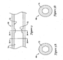
- FIG. 1 illustrates an example endoscopic instrument assembly 10.
- Assembly 10 includes an endoscope 12 and an endoscopic instrument 14 disposed in a working channel (not shown in FIG. 1 , see FIG. 2 for example working channels) defined in endoscope 12.
- Endoscope 12 includes an elongate tubular portion 18 and a proximal handle portion 20 adapted to manipulate and direct the distal end of tubular portion 18.
- Endoscopic instrument 14 may include an end effector 22 and one or more control members 24 that may manipulate or otherwise control end effector 22.
- end effector 22 may be a biopsy forceps or linkage mechanism as depicted in FIG. 1 .
- end effector 22 may be a snare loop, scissors, punch, needle, and the like, or any other suitable devices.
- Control member 24 may include a thumb ring 26 and a displaceable spool 28, which can be used to manipulate and/or actuate end effector 22.
- FIG. 2 is a cross-sectional view of tubular portion 18 of endoscope 12.
- tubular portion 18 may include one or more channels.
- One or more of these channels, for example channel 30, may be provided for receiving an optical scope or camera device 32 (which may be built therein).
- a number of additional lumens 34/36/38/40 may be included for receiving control wires 42/44/46/48 that may extend from the handle portion 20 through the tubular portion 18.
- One or more working channels 50/52/54/56 may also be provided for receiving endoscopic instruments, for example endoscopic instrument 14, therethrough.
- Other lumens 58/60 may be provided for other purposes.
- tubular portion 18 could also be a tubular medical device other than an endoscope, such as a catheter or guiding tube that includes any number of the features and characteristics of similar devices disclosed herein. Therefore, to the extent applicable, discussion found below relating to channels and instruments may also be applicable to tubular medical devices such as catheters or guiding, tubes that include one, two, three or more lumens or channels that are configured to accommodate instruments.
- Working channel 52 has a non-circular cross-sectional shape.
- the cross-sectional shape is that of a six-sided polygon (i.e., a hexagon).
- a number of alternative shapes may be utilized without departing from the spirit of the invention.
- the cross-sectional shape may resemble a three, four, five, six, seven, eight, nine, ten, or more sided polygon.
- the polygon may be regular (i.e., all sides having the same length and all angles between the sides being equal) for irregular.
- any other suitable "non-polygonal" shape may be utilized including partially circular shapes, irregular shapes, random shapes, other geometric shapes, or any other suitable shape.
- Other configurations may include a screw thread or helical ridge or groove formed in channel 52. It should be noted that a vast variety of shapes are contemplated for working channel 52 as well as other channels and instruments disclosed herein.
- An endoscopic instrument 62 is disposed in channel 52.
- Instrument 62 has a generally circular cross-sectional shape.
- the differences between the shape of channel 52 and instrument 62 may be desirable for a number of reasons. For example, because of the differences in the shape, the blank or vacant space between channel 52 and instrument 62 may allow for fluids to be infused or aspirated through channel 52 while instrument 62 is in place.
- a secondary device e.g., a needle, guidewire, etc.
- the converse of working channel 52 and instrument 62 is working channel 56 and endoscopic instrument 64.
- channel 56 has a generally circular cross-sectional shape while instrument 64 has a non-circular cross-sectional shape. This arrangement may be desirable for similar reasons as the arrangement of channel 52 and instrument 62.
- channels 52/56 and instruments 62/64 may also reduce the surface area in which channels 52/56 and instruments 62/64 are in contact. Reducing surface area contact or otherwise providing space between the working channel and the endoscopic instrument may reduce “backlash” (also known as "whip”). Backlash is understood to be a phenomenon where rotation or other manipulations of an instrument (e.g. instruments 62/64) on one end is not immediately translated to the other end of the instrument until, after a certain amount of un-translated motion occurs, the instrument abruptly translates the motion and/or otherwise "whips" around to catch up with the motion.
- backlash also known as "whip”
- Channel 50 is similar to channel 52 in that it has a non-circular cross-sectional shape. Unlike channel 52, however, is that endoscopic instrument 14 disposed in channel 50 also has a non-circular cross-sectional shape.
- the shapes of channel 50 and instrument 14 are, thus, complementary. i.e., the inner surface of working channel 50 has an inner perimeter and the outer surface of endoscopic instrument 14 has an outer perimeter, and the inner perimeter and the outer perimeter are substantially equal.
- the complementary shapes allow instrument 14 to fit within channel 50 much like how a key fits in a lock.
- Utilizing a "lock-and-key" relationship between channel 50 and instrument 14 may be desirable for a number of reasons. For example, using complementary shapes allows the user to keep track of the orientation of instrument 14 within channel 50. This may be particularly useful when the endoscopic intervention depends on instrument 14 having a particular orientation and/or when it is helpful to the clinician to know what orientation instrument 14 is in at any given time. For example, it may be useful for a clinician to know whether a particular end effector 22 (e.g., a biopsy forceps) is "rightside-up” or "upside-down” prior to attempting to actuate the end effector 22.
- a particular end effector 22 e.g., a biopsy forceps
- instrument 14 may also include a visual indicia of origin (not shown) such as a colored marker or image that indicates the orientation of instrument 14.
- a visual indicia of origin such as a colored marker or image that indicates the orientation of instrument 14.
- a number of alternative indicia of origin may also be used without departing from the spirit of the invention.
- Instrument 14' is disposed in channel 54 and is similar to instrument 14 except that the cross-sectiorial shape of instrument 14' is defined by a sleeve or coating 66 disposed on the outer surface of instrument 14'.
- Sleeve 66 allows an otherwise round instrument 14' to utilize the lock-and-key relationship described above and take advantage of its desirable properties.
- Sleeve 66 may include a number of different materials.
- sleeve 66 may comprise a polymer such as polytetrafluoroethylene (PTFE), ethylene tetrafluoroethylene (ETFE), fluorinated ethylene propylene (FEP), polyoxymethylene (POM, for example, DELRIN® available from DuPont), polyether block ester, polyurethane, polypropylene (PP), polyvinylchloride (PVC), polyether-ester (for example, ARNITEL® available from DSM Engineering Plastics), ether or ester based copolymers (for example, butylene/poly(alkylene ether) phthalate and/or other polyester elastomers such as HYTREL® available from DuPont), polyamide (for example, DURETHAN® available from Bayer or CRISTAMID® available from Elf Atochem), elastomeric polyamides, block polyamide/ethers, polyether block amide (PEBA, for example available under the trade
- lubricious polymers may desirably improve the ability for instrument 14' to move within channel 54.
- sleeve 66 can also be applied to the outer surface of instrument 14 or any other instrument having a non-circular cross-sectional shape. Sleeves or lubricious coatings may also be utilized for channels and other instruments described herein so that these instruments may more easily move within these channels.
- Endoscopic instrument assembly 10 may be used by disposing tubular portion 18 within a body lumen.
- tubular portion 18 may extend through the mouth of a patient, down through the esophagus, and into the stomach.
- instrument 14 (or any other instrument described herein) can extend through the appropriate working channel and into the body lumen. Inside the body lumen, the instrument may be actuated so as to perform its intended intervention.
- cross-sectional shapes are contemplated for the various working channels and endoscopic instruments described herein.
- a number of different polygons e.g., one, two, three, four, five, six, seven, eight, nine, or more sided
- partially rounded, irregular, geometric, non-geometric, or other shapes can be used for any of the channels or instruments without departing from the spirit of the invention.
- a cross-sectional shape may be described as an inner or outer diameter, an inner or outer perimeter, or by any other suitable designation. To the extent applicable, these descriptions can be used interchangeably.
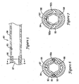
- FIG. 3 illustrates a cross-section of another example working channel 68 that has an inner surface 70 with a first region 72 having a non-circular cross-sectional shape and a second region 74 with a generally circular cross-sectional shape.
- a transverse cross-sectional representation of first region 72 is depicted in FIG. 3A and a transverse cross-sectional representation of second region 74 is depicted in FIG. 3B .
- FIG. 3A A transverse cross-sectional representation of first region 72 is depicted in FIG. 3A and a transverse cross-sectional representation of second region 74 is depicted in FIG. 3B .
- FIG. 4 illustrates a side view of another example endoscopic instrument 114 that has an outer surface 76 with a first region 78 having a non-circular cross-sectional shape and a second region 80 with a generally circular cross-sectional shape.
- a transverse cross-sectional representation of first region 78 is depicted in FIG. 4A and a transverse cross-sectional representation of second region 80 is depicted in FIG. 4B :
- Instrument 114 and channel 68 may be used together or with any other suitable partner. When used together, it can be appreciated that when non-circular first region 78 of instrument 114 engages non-circular first region 72 of channel 68, instrument 114 "keys" channel 68. Conversely, when first region 78 of instrument 114 is disposed adjacent second region 74 of channel 68, instrument 114 can be more easily rotated within channel 68. The combination of these design features allows the clinician to take advantage of the desirable properties of both circular and non-circular devices by simply shifting the longitudinal position of instrument 114 relative to channel 68.
- non-circular cross-sectional shape may provide the endoscopic assembly with a number of desirable features. For example, because a substantial portion of the length of channel 68 and/or instrument 114 have a generally circular cross-sectional shape, non-circular first regions 72/78, when not engaged with one-another, may have reduced surface area contact with circular second regions 74/80. This relationship can reduce backlash and allow for fluid infusion and/or aspiration. Similarly, when non-circular first regions 72/78 are engaged with one another, they may desirably have improved orientation compatibility and otherwise take advantage of the desirable benefits of the "lock-and-key" arrangement.
- first regions 72/78 can vary in a number of different embodiments.
- non-circular first regions 72/78 can span any portion of the length of either channel 68 or instrument 114.
- differing embodiments of channel 68 and instrument 114 may include one, two, three, four, or more first regions 72/78.
- the various non-circular first regions 72/78 can be positioned at essentially any longitudinal position along channel 68 and instrument 114.
- FIGS. 3 and 4 illustrate first regions 72/78 being positioned away from the ends of channel 68 and instrument 114.
- shape of first regions 72/78 can vary to be any useful shape.
- FIG. 5 illustrates another example channel 82 that is similar to other channels described herein.
- Channel 82 includes an inner surface 83 having a section 84 with a generally circular cross-sectional shape and another section 86 having a non-circular cross-sectional shape.
- Section 86 may include a rotatable member 87 that is rotatable within section 84 as best seen in FIG. 6 .
- rotatable member 87 includes a plurality of teeth or gears 88.
- a control member or rod 90 having a gear 92 can be extended through an opening 93 in section 84 and into engagement with teeth 88. Rod 90 extends proximally to a position accessible by the clinician.
- rod 90 and gears 88 function much like a worm gear and this configuration can be utilized to rotate section 86 when desired.
- a second rod 90a may also be utilized on the opposing side of section 84, and/or a motor may be disposed in or adjacent working channel 82 and be coupled to member 87 for rotating member 87.
- rotatable member 87 and/or rod 90 may have mating or complimentary screw threads (or a screw thread on one structure and a gear on then other to drive the screw thread) that provide essentially the same features.
- Rod 90 may utilize any number of different forms and/or material compositions.
- rod 90 may be made from a metal or metal alloy.
- suitable metals and metal alloys include stainless steel, such as 304Vk, 304L, and 316LV stainless steel; mild steel; nickel-titanium alloy suck as linear-elastic or super-elastic nitinol, nickel-chromium alloy, nickel-chromium-iron alloy, cobalt alloy, tungsten or tungsten alloys, MP35-N (having a composition of about 35% Ni, 35% Co, 20% Cr, 9.75% Mo, a maximum 1% Fe, a maximum 1% Ti, a maximum 0.25% C, a maximum 0.15% Mn, and a maximum 0.15% Si), hastelloy, monel 400, inconel 825, or the like; other Co-Cr alloys; platinum enriched stainless steel; or other suitable material.
- rod 90 may comprise a polymer, metal-polymer composite, and
- Section 86 and rotatable member 87 may be desirable for a number of reasons.
- a clinician may dispose an endoscopic instrument (such as any of those shown or described herein) through channel 82 and then need to rotate the instrument.
- an endoscopic instrument such as any of those shown or described herein
- a clinician can rotate rod 90 to rotate rotatable member 87 and, consequently, the instrument.
- rotatable member 87 Another desirable feature of rotatable member 87 is that because it may be placed at or near the distal end of channel 82, torque can be applied directly at the distal end of the instrument rather than at the proximal end of the instrument. This may result in a more efficient transfer of torque and it may reduce the incidence of backlash because of the fact that torque is being applied to the instrument at a location that is much closer to where torque transmission is desired (e.g., near the end effector).
- FIG. 7 illustrates an alternative section 186 that includes rotatable member 187 that is rotatable within section 84 of channel 82.
- One or more wires 194 are disposed about rotatable member 187, with ends 192a/192b of wires 194 extending into openings 93 and then extending proximally to a location accessible by the clinician. Ends 192a/192b or wires 194 can be pulled by the clinician in order to rotate section 186. For the same reasons set forth above, this may help to efficiently transmit torque and reduce backlash.
- FIG. 8 illustrates another example working channel 96 that is similar in form and function to the other channels described above.
- a plurality of instruments 98a/98b are disposed in channel 96.
- This arrangement demonstrates that multiple instruments 98a/98b, each having a non-circular cross-sectional shape, can be disposed in channel 96.
- instruments 98a/98b have a combined shape that is complimentary to the cross-sectional shape of channel 96.
- the combination of instruments 98a/98b thus, may take advantage of the desirable features of the "lock-and-key" arrangement described above.
- a plurality of generally circular instruments 99a/99b may be disposed in channel 96 as shown in FIG. 9 .
Abstract
Description
- This invention pertains broadly to surgical instruments. More particularly, this invention pertains to an endoscope and endoscopic instruments that are disposed in a working channel of the endoscope.
- A wide variety of medical devices have been developed for medical use, for example, endoscopic and/or surgical use. Some of these devices include endoscopes, endoscopic instruments, and other related devices that have certain characteristics. Of the known medical devices, each has certain advantages and disadvantages. There is an ongoing need to provide alternative designs and methods of making and using medical devices. A device according to the preamble of claim 1 is known from
US 4,742,817 . - The disclosure provides design, material, and manufacturing method alternatives for medical devices, for example, endoscopes, endoscopic instruments, and endoscopic instrument assemblies. An example endoscopic instrument assembly includes an endoscope having a working channel and an endoscopic instrument slidably disposed in the working channel. The inside surface of the working channel and the outside surface of the endoscopic instrument each have a non-circular cross-sectional shape along at least a portion of their respective lengths. Methods for making and using medical devices including endoscopic instrument assemblies are also disclosed. Some of these and other features and characteristics of the inventive devices and methods are described in more detail below.
- The above summary of some embodiments is not intended to describe each disclosed embodiment or every implementation of the present invention. The Figure, and Detailed. Description, which follow, more particularly exemplify these embodiments.
- A device according to the invention is defined in claim 1.
- The invention may be more completely understood in consideration of the following detailed description of various embodiments of the invention in connections with the accompanying drawings, in which:
-
FIG. 1 is side view of an example endoscopic instrument assembly; -
FIG. 2 is a cross-section across line 2 - 2 inFIG. 1 ; -
FIG. 3 is a cross-sectional view of an example working channel; -
FIG. 3A is a cross-section acrossline 3A - 3A inFIG. 3 ; -
FIG. 3B is a cross-section acrossline 3B - 3B inFIG. 3 ; -
FIG. 4 is a side view of a portion of an example endoscopic instrument; -
FIG. 4A is a cross-section acrossline 4A - 4A inFIG. 4 ; -
FIG. 4B is a cross-section acrossline 4B - 4B inFIG. 4 ; -
FIG. 5 is a cross-sectional view of another example working channel; -
FIG. 6 is a cross-section across line 6 - 6 inFIG. 5 ; -
FIG. 7 is an alternative example cross-section taken across line 6-6 inFIG. 5 ; -
FIG. 8 is a cross-sectional view of another example working channel having a plurality of endoscopic instruments disposed therein; and -
FIG. 9 is a cross-sectional view of the working channel shown inFIG. 8 having a plurality of different instruments disposed therein. - The embodiments of
figures 1-7, 9 do not fall under the scope of claim 1, and provide background information only. - The following description should be read with reference to the drawings wherein like reference numerals indicate like elements throughout the several views.
-
FIG. 1 illustrates an exampleendoscopic instrument assembly 10.Assembly 10 includes anendoscope 12 and anendoscopic instrument 14 disposed in a working channel (not shown inFIG. 1 , seeFIG. 2 for example working channels) defined inendoscope 12.Endoscope 12 includes an elongatetubular portion 18 and aproximal handle portion 20 adapted to manipulate and direct the distal end oftubular portion 18. -
Endoscopic instrument 14 may include anend effector 22 and one ormore control members 24 that may manipulate or otherwise controlend effector 22. In some embodiments,end effector 22 may be a biopsy forceps or linkage mechanism as depicted inFIG. 1 . Alternatively,end effector 22 may be a snare loop, scissors, punch, needle, and the like, or any other suitable devices.Control member 24 may include athumb ring 26 and adisplaceable spool 28, which can be used to manipulate and/or actuateend effector 22. Some additional details regarding suitable types of end effectors and control members (which can also be described as or take the form of handles) can be found inU.S. Pat. Nos. 6,537,205 ;6,840,900 ;6,454,702 ;6,881,186 ;6.235,026 ; and6,517,539 . -
FIG. 2 is a cross-sectional view oftubular portion 18 ofendoscope 12. Here it can be seen thattubular portion 18 may include one or more channels. One or more of these channels, forexample channel 30, may be provided for receiving an optical scope or camera device 32 (which may be built therein). A number ofadditional lumens 34/36/38/40 may be included for receivingcontrol wires 42/44/46/48 that may extend from thehandle portion 20 through thetubular portion 18. One ormore working channels 50/52/54/56 may also be provided for receiving endoscopic instruments, for exampleendoscopic instrument 14, therethrough.Other lumens 58/60 may be provided for other purposes. Some additional details regarding endoscopes are described in general inU.S. Pat. No. 5,179,935 to Miyagi . It should be noted thattubular portion 18 could also be a tubular medical device other than an endoscope, such as a catheter or guiding tube that includes any number of the features and characteristics of similar devices disclosed herein. Therefore, to the extent applicable, discussion found below relating to channels and instruments may also be applicable to tubular medical devices such as catheters or guiding, tubes that include one, two, three or more lumens or channels that are configured to accommodate instruments. -
Working channel 52, as depicted inFIG. 2 , has a non-circular cross-sectional shape. In this example, the cross-sectional shape is that of a six-sided polygon (i.e., a hexagon). It can be appreciated that a number of alternative shapes may be utilized without departing from the spirit of the invention. For example, the cross-sectional shape may resemble a three, four, five, six, seven, eight, nine, ten, or more sided polygon. The polygon may be regular (i.e., all sides having the same length and all angles between the sides being equal) for irregular. In addition, any other suitable "non-polygonal" shape may be utilized including partially circular shapes, irregular shapes, random shapes, other geometric shapes, or any other suitable shape. Other configurations may include a screw thread or helical ridge or groove formed inchannel 52. It should be noted that a vast variety of shapes are contemplated for workingchannel 52 as well as other channels and instruments disclosed herein. - An
endoscopic instrument 62 is disposed inchannel 52.Instrument 62 has a generally circular cross-sectional shape. The differences between the shape ofchannel 52 andinstrument 62 may be desirable for a number of reasons. For example, because of the differences in the shape, the blank or vacant space betweenchannel 52 andinstrument 62 may allow for fluids to be infused or aspirated throughchannel 52 whileinstrument 62 is in place. In some instances, a secondary device (e.g., a needle, guidewire, etc.) may also be disposed inchannel 56adjacent instrument 62. The converse of workingchannel 52 andinstrument 62 is workingchannel 56 andendoscopic instrument 64. Here,channel 56 has a generally circular cross-sectional shape whileinstrument 64 has a non-circular cross-sectional shape. This arrangement may be desirable for similar reasons as the arrangement ofchannel 52 andinstrument 62. - In addition, the differences in shape between
channels 52/56 andinstruments 62/64 may also reduce the surface area in whichchannels 52/56 andinstruments 62/64 are in contact. Reducing surface area contact or otherwise providing space between the working channel and the endoscopic instrument may reduce "backlash" (also known as "whip"). Backlash is understood to be a phenomenon where rotation or other manipulations of an instrument (e.g. instruments 62/64) on one end is not immediately translated to the other end of the instrument until, after a certain amount of un-translated motion occurs, the instrument abruptly translates the motion and/or otherwise "whips" around to catch up with the motion. -
Channel 50 is similar tochannel 52 in that it has a non-circular cross-sectional shape. Unlikechannel 52, however, is thatendoscopic instrument 14 disposed inchannel 50 also has a non-circular cross-sectional shape. The shapes ofchannel 50 andinstrument 14 are, thus, complementary. i.e., the inner surface of workingchannel 50 has an inner perimeter and the outer surface ofendoscopic instrument 14 has an outer perimeter, and the inner perimeter and the outer perimeter are substantially equal. The complementary shapes allowinstrument 14 to fit withinchannel 50 much like how a key fits in a lock. - Utilizing a "lock-and-key" relationship between
channel 50 andinstrument 14 may be desirable for a number of reasons. For example, using complementary shapes allows the user to keep track of the orientation ofinstrument 14 withinchannel 50. This may be particularly useful when the endoscopic intervention depends oninstrument 14 having a particular orientation and/or when it is helpful to the clinician to know whatorientation instrument 14 is in at any given time. For example, it may be useful for a clinician to know whether a particular end effector 22 (e.g., a biopsy forceps) is "rightside-up" or "upside-down" prior to attempting to actuate theend effector 22. To further aid this orientation capability,instrument 14 may also include a visual indicia of origin (not shown) such as a colored marker or image that indicates the orientation ofinstrument 14. Of course, a number of alternative indicia of origin may also be used without departing from the spirit of the invention. -
Instrument 14' is disposed inchannel 54 and is similar toinstrument 14 except that the cross-sectiorial shape ofinstrument 14' is defined by a sleeve orcoating 66 disposed on the outer surface ofinstrument 14'.Sleeve 66 allows an otherwiseround instrument 14' to utilize the lock-and-key relationship described above and take advantage of its desirable properties. -
Sleeve 66 may include a number of different materials. For example, sleeve 66 may comprise a polymer such as polytetrafluoroethylene (PTFE), ethylene tetrafluoroethylene (ETFE), fluorinated ethylene propylene (FEP), polyoxymethylene (POM, for example, DELRIN® available from DuPont), polyether block ester, polyurethane, polypropylene (PP), polyvinylchloride (PVC), polyether-ester (for example, ARNITEL® available from DSM Engineering Plastics), ether or ester based copolymers (for example, butylene/poly(alkylene ether) phthalate and/or other polyester elastomers such as HYTREL® available from DuPont), polyamide (for example, DURETHAN® available from Bayer or CRISTAMID® available from Elf Atochem), elastomeric polyamides, block polyamide/ethers, polyether block amide (PEBA, for example available under the trade name PEBAX®), ethylene vinyl acetate copolymers (EVA), silicones, polyethylene (PE), Marlex high-density polyethylene, Marlex low-density polyethylene, linear low density polyethylene (for example REXELL®), polyester, polybutylene terephthalate (PBT), polyethylene terephthalate (PET), polytrimethylene terephthalate, polyethylene naphthalate (PEN), polyetheretherketone (PEEK), polyimide (PI), polyetherimide (PEI), polyphenylene sulfide (PPS), polyphenylene oxide (PPO), poly paraphenylene terephthalamide (for example, KEVLAR®), polysulfone, nylon, nylon-12 (such as GRILAMID® available from EMS American Grilon), perfluoro(propyl vinyl ether) (PFA), ethylene vinyl alcohol, polyolefin, polystyrene, epoxy, polyvinylidene chloride (PVdC), polycarbonates, ionomers, biocompatible polymers, other suitable materials, or mixtures, combinations, copolymers thereof, polymer/metal composites, and the like. In some embodiments, lubricious polymers (including those listed above such as polytetrafluoroethylene) may desirably improve the ability forinstrument 14' to move withinchannel 54. Moreover, because increased lubricity may be desirable,sleeve 66 can also be applied to the outer surface ofinstrument 14 or any other instrument having a non-circular cross-sectional shape. Sleeves or lubricious coatings may also be utilized for channels and other instruments described herein so that these instruments may more easily move within these channels. -
Endoscopic instrument assembly 10 may be used by disposingtubular portion 18 within a body lumen. For example, for an endoscopic procedure that accesses the stomach,tubular portion 18 may extend through the mouth of a patient, down through the esophagus, and into the stomach. Once positioned, instrument 14 (or any other instrument described herein) can extend through the appropriate working channel and into the body lumen. Inside the body lumen, the instrument may be actuated so as to perform its intended intervention. - It is once again useful to consider that a number of different cross-sectional shapes are contemplated for the various working channels and endoscopic instruments described herein. For example, a number of different polygons (e.g., one, two, three, four, five, six, seven, eight, nine, or more sided), partially rounded, irregular, geometric, non-geometric, or other shapes can be used for any of the channels or instruments without departing from the spirit of the invention. It is worth noting that a cross-sectional shape may be described as an inner or outer diameter, an inner or outer perimeter, or by any other suitable designation. To the extent applicable, these descriptions can be used interchangeably.
- In some embodiments, the non-circular cross-sectional shape of working
channels 50/52/54 andinstruments 14/14'/64 extend the full length of each given device. However, this need not be the case. For example,FIG. 3 illustrates a cross-section of anotherexample working channel 68 that has aninner surface 70 with afirst region 72 having a non-circular cross-sectional shape and asecond region 74 with a generally circular cross-sectional shape. A transverse cross-sectional representation offirst region 72 is depicted inFIG. 3A and a transverse cross-sectional representation ofsecond region 74 is depicted inFIG. 3B . Analogously,FIG. 4 illustrates a side view of another exampleendoscopic instrument 114 that has anouter surface 76 with afirst region 78 having a non-circular cross-sectional shape and asecond region 80 with a generally circular cross-sectional shape. A transverse cross-sectional representation offirst region 78 is depicted inFIG. 4A and a transverse cross-sectional representation ofsecond region 80 is depicted inFIG. 4B : -
Instrument 114 andchannel 68. may be used together or with any other suitable partner. When used together, it can be appreciated that when non-circularfirst region 78 ofinstrument 114 engages non-circularfirst region 72 ofchannel 68,instrument 114 "keys"channel 68. Conversely, whenfirst region 78 ofinstrument 114 is disposed adjacentsecond region 74 ofchannel 68,instrument 114 can be more easily rotated withinchannel 68. The combination of these design features allows the clinician to take advantage of the desirable properties of both circular and non-circular devices by simply shifting the longitudinal position ofinstrument 114 relative to channel 68. - Designs like these that utilize a non-circular cross-sectional shape along only a portion of the length may provide the endoscopic assembly with a number of desirable features. For example, because a substantial portion of the length of
channel 68 and/orinstrument 114 have a generally circular cross-sectional shape, non-circularfirst regions 72/78, when not engaged with one-another, may have reduced surface area contact with circularsecond regions 74/80. This relationship can reduce backlash and allow for fluid infusion and/or aspiration. Similarly, when non-circularfirst regions 72/78 are engaged with one another, they may desirably have improved orientation compatibility and otherwise take advantage of the desirable benefits of the "lock-and-key" arrangement. - The length, number, position, and shape of
first regions 72/78 can vary in a number of different embodiments. For example, non-circularfirst regions 72/78 can span any portion of the length of eitherchannel 68 orinstrument 114. Likewise, differing embodiments ofchannel 68 andinstrument 114 may include one, two, three, four, or morefirst regions 72/78. In addition, the various non-circularfirst regions 72/78 can be positioned at essentially any longitudinal position alongchannel 68 andinstrument 114. For example,FIGS. 3 and4 illustratefirst regions 72/78 being positioned away from the ends ofchannel 68 andinstrument 114. However, this need not be the case as numerous embodiments are contemplated that positionfirst regions 72/78 adjacent the proximal end, distal end, or both ofchannel 68 andinstrument 114, respectively. Similarly, the shape offirst regions 72/78 can vary to be any useful shape. -
FIG. 5 illustrates anotherexample channel 82 that is similar to other channels described herein.Channel 82 includes aninner surface 83 having asection 84 with a generally circular cross-sectional shape and anothersection 86 having a non-circular cross-sectional shape.Section 86 may include arotatable member 87 that is rotatable withinsection 84 as best seen inFIG. 6 . Here it can be seen thatrotatable member 87 includes a plurality of teeth or gears 88. A control member orrod 90 having agear 92 can be extended through anopening 93 insection 84 and into engagement withteeth 88.Rod 90 extends proximally to a position accessible by the clinician. Withgear 92 engaged withteeth 88, rotation ofrod 90 rotatesrotatable member 87. Thus,rod 90 and gears 88 function much like a worm gear and this configuration can be utilized to rotatesection 86 when desired. In some embodiments, asecond rod 90a may also be utilized on the opposing side ofsection 84, and/or a motor may be disposed in or adjacent workingchannel 82 and be coupled tomember 87 for rotatingmember 87. In alternative embodiments,rotatable member 87 and/orrod 90 may have mating or complimentary screw threads (or a screw thread on one structure and a gear on then other to drive the screw thread) that provide essentially the same features. -
Rod 90 may utilize any number of different forms and/or material compositions. For example,rod 90 may be made from a metal or metal alloy. Some examples of suitable metals and metal alloys include stainless steel, such as 304Vk, 304L, and 316LV stainless steel; mild steel; nickel-titanium alloy suck as linear-elastic or super-elastic nitinol, nickel-chromium alloy, nickel-chromium-iron alloy, cobalt alloy, tungsten or tungsten alloys, MP35-N (having a composition of about 35% Ni, 35% Co, 20% Cr, 9.75% Mo, a maximum 1% Fe, a maximum 1% Ti, a maximum 0.25% C, a maximum 0.15% Mn, and a maximum 0.15% Si), hastelloy, monel 400, inconel 825, or the like; other Co-Cr alloys; platinum enriched stainless steel; or other suitable material. Alternatively,rod 90 may comprise a polymer, metal-polymer composite, and the like, or any other suitable material. -
Section 86 androtatable member 87 may be desirable for a number of reasons. For example, a clinician may dispose an endoscopic instrument (such as any of those shown or described herein) throughchannel 82 and then need to rotate the instrument. With a non-circular section of the instrument "keyed" withsection 86, a clinician can rotaterod 90 to rotaterotatable member 87 and, consequently, the instrument. - Another desirable feature of
rotatable member 87 is that because it may be placed at or near the distal end ofchannel 82, torque can be applied directly at the distal end of the instrument rather than at the proximal end of the instrument. This may result in a more efficient transfer of torque and it may reduce the incidence of backlash because of the fact that torque is being applied to the instrument at a location that is much closer to where torque transmission is desired (e.g., near the end effector). -
FIG. 7 illustrates analternative section 186 that includesrotatable member 187 that is rotatable withinsection 84 ofchannel 82. One ormore wires 194 are disposed aboutrotatable member 187, withends 192a/192b ofwires 194 extending intoopenings 93 and then extending proximally to a location accessible by the clinician.Ends 192a/192b orwires 194 can be pulled by the clinician in order to rotatesection 186. For the same reasons set forth above, this may help to efficiently transmit torque and reduce backlash. -
FIG. 8 illustrates anotherexample working channel 96 that is similar in form and function to the other channels described above. A plurality ofinstruments 98a/98b are disposed inchannel 96. This arrangement demonstrates thatmultiple instruments 98a/98b, each having a non-circular cross-sectional shape, can be disposed inchannel 96. According to the invention,instruments 98a/98b have a combined shape that is complimentary to the cross-sectional shape ofchannel 96. The combination ofinstruments 98a/98b, thus, may take advantage of the desirable features of the "lock-and-key" arrangement described above. Alternatively, not according to the invention, a plurality of generallycircular instruments 99a/99b may be disposed inchannel 96 as shown inFIG. 9 . This arrangement may be desirable by reducing the surface area contract betweeninstruments 99a/99b andchannel 96 as described above. Of course, a combination of these arrangements is also contemplated where a non-circular instrument (e.g.,instrument 98a) and a generally circular instrument (e.g.,instrument 99a) are disposed inchannel 96. Regardless of what arrangement is utilized, any combination ofinstruments 98a/98b/99a/99b may be used with any suitable channel, including any of those described herein. - It should be understood that this disclosure is, in many respects, only illustrative. Changes may be made in details, particularly in matters of shape, size, and arrangement of steps without exceeding the scope of the invention. The invention's scope is, of course, defined in the language in which the appended claims are expressed.
Claims (14)
- An endoscopic instrument assembly, comprising:an endoscope defining a working channel therein;an inner surface defined in the endoscope adjacent the working channel, wherein the inner surface has a polygonal cross-sectional shape;an endoscopic instrument slidably disposed in the working channel, the endoscopic instrument having an outer surface with a non-circular cross-sectional shape; and characterised in that the assembly further comprises:a endoscopic instrument disposed in the working channel, the second endoscopic instrument having a second outer surface with a non-circular cross-sectional shape,wherein the outer surface of the endoscopic instrument and the second outer surface of the second endoscopic instrument define a combined outer surface, and wherein the shape of the combined outer surface is complementary with the shape of the inner surface of the working channel.
- The endoscopic instrument assembly of claim 1, wherein the outer surface of the working channel has a polygonal cross-sectional shape.
- The endoscopic instrument assembly of claim 1, wherein the inner surface of the working channel has a length and wherein the inner surface has a non-circular cross-sectional shape that spans the length.
- The endoscopic instrument assembly of claim 1, wherein the inner surface of the working channel has a length and wherein the inner surface has a non-circular cross-sectional shape along only a portion of the length.
- The endoscopic instrument assembly of claim 4, wherein the portion of the length of the inner surface having a non-circular cross-sectional shape is rotatable.
- The endoscopic instrument assembly of claim 5, further comprising means for rotating the portion of the length of the inner surface having a non-circular aoss-sectionat shape.
- The endoscopic instrument assembly of claim 6, wherein means for rotating the portion of the length of the inner surface having a non-circular cross-sectional shape comprises either a rod and a gear disposed adjacent the rod or one or more wires.
- The endoscopic instrument assembly of claim 1, wherein the outer surface of the endoscopic instrument has a length and wherein the outer surface has a non-circular cross-sectional shape either that spans the length or along only a portion of the length.
- The endoscopic instrument assembly of claim 1, wherein the inner surface of the working channel, the outer surface of the endoscopic instrument, or both includes a coating.
- The endoscopic instrument assembly of claim 1, further comprising an end effector disposed at a distal end of the endoscopic instrument.
- The endoscopic instrument assembly of claim 1,
wherein the inner surface of the working channel has an inner perimeter and the outer surface of the endoscopic instrument has an outer perimeter, and wherein the inner perimeter and the outer perimeter are substantially equal. - The endoscopic instrument assembly of claim 1, wherein the inner surface of the working channel has a hexagonal cross-sectional shape.
- The endoscopic instrument assembly of claim 6, wherein the rotatable portion includes a plurality of teeth and wherein the means for rotating comprises a gear engagable with the plurality of teeth.
- The endoscopic instrument assembly of claim 6, wherein the means for rotating includes one or more wires disposed about the rotatable portion and extending proximally therefrom.
Applications Claiming Priority (2)
| Application Number | Priority Date | Filing Date | Title |
|---|---|---|---|
| US11/386,861 US7918783B2 (en) | 2006-03-22 | 2006-03-22 | Endoscope working channel with multiple functionality |
| PCT/US2006/048953 WO2007111670A1 (en) | 2006-03-22 | 2006-12-21 | Endoscope working channel with multiple functionality |
Publications (2)
| Publication Number | Publication Date |
|---|---|
| EP2004032A1 EP2004032A1 (en) | 2008-12-24 |
| EP2004032B1 true EP2004032B1 (en) | 2011-05-11 |
Family
ID=38111540
Family Applications (1)
| Application Number | Title | Priority Date | Filing Date |
|---|---|---|---|
| EP06848001A Not-in-force EP2004032B1 (en) | 2006-03-22 | 2006-12-21 | Endoscope working channel with multiple functionality |
Country Status (4)
| Country | Link |
|---|---|
| US (3) | US7918783B2 (en) |
| EP (1) | EP2004032B1 (en) |
| AT (1) | ATE508675T1 (en) |
| WO (1) | WO2007111670A1 (en) |
Families Citing this family (107)
| Publication number | Priority date | Publication date | Assignee | Title |
|---|---|---|---|---|
| US20080275298A1 (en) * | 2004-10-11 | 2008-11-06 | Novation Science, Llc | Dual View Endoscope |
| US8872906B2 (en) | 2005-01-05 | 2014-10-28 | Avantis Medical Systems, Inc. | Endoscope assembly with a polarizing filter |
| US20080021274A1 (en) * | 2005-01-05 | 2008-01-24 | Avantis Medical Systems, Inc. | Endoscopic medical device with locking mechanism and method |
| JP4616058B2 (en) * | 2005-04-14 | 2011-01-19 | オリンパス株式会社 | Endoscope attachment, endoscope treatment tool, and endoscope system |
| US9962066B2 (en) | 2005-12-30 | 2018-05-08 | Intuitive Surgical Operations, Inc. | Methods and apparatus to shape flexible entry guides for minimally invasive surgery |
| US7930065B2 (en) | 2005-12-30 | 2011-04-19 | Intuitive Surgical Operations, Inc. | Robotic surgery system including position sensors using fiber bragg gratings |
| WO2007087421A2 (en) | 2006-01-23 | 2007-08-02 | Avantis Medical Systems, Inc. | Endoscope |
| US20070265494A1 (en) * | 2006-05-10 | 2007-11-15 | Boston Scientific Scimed Inc. | Flexible and retractable endoscope elevator |
| US20080064931A1 (en) * | 2006-06-13 | 2008-03-13 | Intuitive Surgical, Inc. | Minimally invasive surgical illumination |
| US8784435B2 (en) * | 2006-06-13 | 2014-07-22 | Intuitive Surgical Operations, Inc. | Surgical system entry guide |
| US7993264B2 (en) * | 2006-11-09 | 2011-08-09 | Ams Research Corporation | Orientation adapter for injection tube in flexible endoscope |
| US8715270B2 (en) | 2006-12-01 | 2014-05-06 | Boston Scientific Scimed, Inc. | Multi-part instrument systems and methods |
| US7655004B2 (en) | 2007-02-15 | 2010-02-02 | Ethicon Endo-Surgery, Inc. | Electroporation ablation apparatus, system, and method |
| DE102007008099B4 (en) * | 2007-02-19 | 2021-05-20 | Ingoscope Systems Gmbh | Tube arrangement for an endoscope |
| US7815662B2 (en) | 2007-03-08 | 2010-10-19 | Ethicon Endo-Surgery, Inc. | Surgical suture anchors and deployment device |
| US8064666B2 (en) | 2007-04-10 | 2011-11-22 | Avantis Medical Systems, Inc. | Method and device for examining or imaging an interior surface of a cavity |
| US8075572B2 (en) | 2007-04-26 | 2011-12-13 | Ethicon Endo-Surgery, Inc. | Surgical suturing apparatus |
| US8100922B2 (en) | 2007-04-27 | 2012-01-24 | Ethicon Endo-Surgery, Inc. | Curved needle suturing tool |
| US8568410B2 (en) | 2007-08-31 | 2013-10-29 | Ethicon Endo-Surgery, Inc. | Electrical ablation surgical instruments |
| US8579897B2 (en) | 2007-11-21 | 2013-11-12 | Ethicon Endo-Surgery, Inc. | Bipolar forceps |
| US8262655B2 (en) | 2007-11-21 | 2012-09-11 | Ethicon Endo-Surgery, Inc. | Bipolar forceps |
| US8480657B2 (en) | 2007-10-31 | 2013-07-09 | Ethicon Endo-Surgery, Inc. | Detachable distal overtube section and methods for forming a sealable opening in the wall of an organ |
| US20090112059A1 (en) | 2007-10-31 | 2009-04-30 | Nobis Rudolph H | Apparatus and methods for closing a gastrotomy |
| US8262680B2 (en) | 2008-03-10 | 2012-09-11 | Ethicon Endo-Surgery, Inc. | Anastomotic device |
| US8114072B2 (en) | 2008-05-30 | 2012-02-14 | Ethicon Endo-Surgery, Inc. | Electrical ablation device |
| US8070759B2 (en) | 2008-05-30 | 2011-12-06 | Ethicon Endo-Surgery, Inc. | Surgical fastening device |
| US8317806B2 (en) | 2008-05-30 | 2012-11-27 | Ethicon Endo-Surgery, Inc. | Endoscopic suturing tension controlling and indication devices |
| US8679003B2 (en) | 2008-05-30 | 2014-03-25 | Ethicon Endo-Surgery, Inc. | Surgical device and endoscope including same |
| US8652150B2 (en) | 2008-05-30 | 2014-02-18 | Ethicon Endo-Surgery, Inc. | Multifunction surgical device |
| US8771260B2 (en) | 2008-05-30 | 2014-07-08 | Ethicon Endo-Surgery, Inc. | Actuating and articulating surgical device |
| US8906035B2 (en) | 2008-06-04 | 2014-12-09 | Ethicon Endo-Surgery, Inc. | Endoscopic drop off bag |
| US8403926B2 (en) | 2008-06-05 | 2013-03-26 | Ethicon Endo-Surgery, Inc. | Manually articulating devices |
| US8361112B2 (en) | 2008-06-27 | 2013-01-29 | Ethicon Endo-Surgery, Inc. | Surgical suture arrangement |
| US8888792B2 (en) | 2008-07-14 | 2014-11-18 | Ethicon Endo-Surgery, Inc. | Tissue apposition clip application devices and methods |
| US8262563B2 (en) | 2008-07-14 | 2012-09-11 | Ethicon Endo-Surgery, Inc. | Endoscopic translumenal articulatable steerable overtube |
| US8211125B2 (en) | 2008-08-15 | 2012-07-03 | Ethicon Endo-Surgery, Inc. | Sterile appliance delivery device for endoscopic procedures |
| US8529563B2 (en) | 2008-08-25 | 2013-09-10 | Ethicon Endo-Surgery, Inc. | Electrical ablation devices |
| US8241204B2 (en) | 2008-08-29 | 2012-08-14 | Ethicon Endo-Surgery, Inc. | Articulating end cap |
| US8480689B2 (en) | 2008-09-02 | 2013-07-09 | Ethicon Endo-Surgery, Inc. | Suturing device |
| US8409200B2 (en) | 2008-09-03 | 2013-04-02 | Ethicon Endo-Surgery, Inc. | Surgical grasping device |
| US8114119B2 (en) | 2008-09-09 | 2012-02-14 | Ethicon Endo-Surgery, Inc. | Surgical grasping device |
| US8337394B2 (en) | 2008-10-01 | 2012-12-25 | Ethicon Endo-Surgery, Inc. | Overtube with expandable tip |
| US8157834B2 (en) | 2008-11-25 | 2012-04-17 | Ethicon Endo-Surgery, Inc. | Rotational coupling device for surgical instrument with flexible actuators |
| AU2009322968B2 (en) | 2008-12-05 | 2015-09-10 | Ams Research Corporation | Devices, systems and methods for delivering fluid to tissue |
| US20110046600A1 (en) * | 2008-12-05 | 2011-02-24 | Crank Justin M | Devices, systems, and related methods for delivery of fluid to tissue |
| AU2009322967B2 (en) | 2008-12-05 | 2015-06-11 | Ams Research Corporation | Devices, systems and methods for delivering fluid to tissue |
| CA2744415A1 (en) | 2008-12-05 | 2010-06-10 | Ams Research Corporation | Devices, systems, and related methods for delivery of fluid to tissue |
| US8366657B2 (en) * | 2008-12-05 | 2013-02-05 | Ams Research Corporation | Needleless injection device components, systems, and methods |
| US8172772B2 (en) | 2008-12-11 | 2012-05-08 | Ethicon Endo-Surgery, Inc. | Specimen retrieval device |
| EP2384209A2 (en) * | 2008-12-16 | 2011-11-09 | AMS Research Corporation | Needleless injection device components, systems, and methods |
| CA2744224C (en) | 2008-12-29 | 2016-12-13 | Ams Research Corporation | Method and apparatus for compensating for injection media viscosity in a pressurized drug injection system |
| US8361066B2 (en) | 2009-01-12 | 2013-01-29 | Ethicon Endo-Surgery, Inc. | Electrical ablation devices |
| US8828031B2 (en) | 2009-01-12 | 2014-09-09 | Ethicon Endo-Surgery, Inc. | Apparatus for forming an anastomosis |
| US9226772B2 (en) | 2009-01-30 | 2016-01-05 | Ethicon Endo-Surgery, Inc. | Surgical device |
| US8252057B2 (en) | 2009-01-30 | 2012-08-28 | Ethicon Endo-Surgery, Inc. | Surgical access device |
| US8037591B2 (en) | 2009-02-02 | 2011-10-18 | Ethicon Endo-Surgery, Inc. | Surgical scissors |
| US20100249700A1 (en) * | 2009-03-27 | 2010-09-30 | Ethicon Endo-Surgery, Inc. | Surgical instruments for in vivo assembly |
| US20110015484A1 (en) * | 2009-07-16 | 2011-01-20 | Alvarez Jeffrey B | Endoscopic robotic catheter system |
| US8945045B2 (en) | 2009-07-20 | 2015-02-03 | Ams Research Corporation | Needleless injection device components, systems, and methods |
| AU2010276333B2 (en) * | 2009-07-20 | 2016-09-15 | Ams Research Corporation | Needleless injection device components |
| US9138535B2 (en) | 2009-07-20 | 2015-09-22 | Ams Research Corporation | High pressure injection catheter systems |
| CA2768027A1 (en) | 2009-07-20 | 2011-01-27 | Ams Research Corporation | Devices, systems, and methods for delivering fluid to tissue |
| US20110098704A1 (en) | 2009-10-28 | 2011-04-28 | Ethicon Endo-Surgery, Inc. | Electrical ablation devices |
| US9949630B2 (en) * | 2009-11-04 | 2018-04-24 | The Trustees Of The University Of Pennsylvania | Medical instrument system and method for manipulating target tissue |
| US8608652B2 (en) | 2009-11-05 | 2013-12-17 | Ethicon Endo-Surgery, Inc. | Vaginal entry surgical devices, kit, system, and method |
| US8353487B2 (en) | 2009-12-17 | 2013-01-15 | Ethicon Endo-Surgery, Inc. | User interface support devices for endoscopic surgical instruments |
| US8496574B2 (en) | 2009-12-17 | 2013-07-30 | Ethicon Endo-Surgery, Inc. | Selectively positionable camera for surgical guide tube assembly |
| US9028483B2 (en) | 2009-12-18 | 2015-05-12 | Ethicon Endo-Surgery, Inc. | Surgical instrument comprising an electrode |
| US8506564B2 (en) | 2009-12-18 | 2013-08-13 | Ethicon Endo-Surgery, Inc. | Surgical instrument comprising an electrode |
| US9005198B2 (en) | 2010-01-29 | 2015-04-14 | Ethicon Endo-Surgery, Inc. | Surgical instrument comprising an electrode |
| WO2011104960A1 (en) * | 2010-02-26 | 2011-09-01 | オリンパスメディカルシステムズ株式会社 | Endoscope apparatus |
| US8979797B2 (en) | 2010-12-16 | 2015-03-17 | Ams Research Corporation | High pressure delivery system and method for treating pelvic disorder using large molecule therapeutics |
| US10092291B2 (en) | 2011-01-25 | 2018-10-09 | Ethicon Endo-Surgery, Inc. | Surgical instrument with selectively rigidizable features |
| US9233241B2 (en) | 2011-02-28 | 2016-01-12 | Ethicon Endo-Surgery, Inc. | Electrical ablation devices and methods |
| US9254169B2 (en) | 2011-02-28 | 2016-02-09 | Ethicon Endo-Surgery, Inc. | Electrical ablation devices and methods |
| US9314620B2 (en) | 2011-02-28 | 2016-04-19 | Ethicon Endo-Surgery, Inc. | Electrical ablation devices and methods |
| US9049987B2 (en) | 2011-03-17 | 2015-06-09 | Ethicon Endo-Surgery, Inc. | Hand held surgical device for manipulating an internal magnet assembly within a patient |
| DK2719936T3 (en) * | 2011-06-13 | 2016-09-26 | Nissei Electric Co Ltd | Resin pipe for guiding thread, process for preparing the resin pipe to the guidewire and guidewire |
| CN103619400B (en) * | 2011-06-16 | 2015-12-02 | 奥林巴斯株式会社 | Insertion instrument in body |
| US8942530B2 (en) | 2011-09-20 | 2015-01-27 | San Marino Capital, Inc. | Endoscope connector method and apparatus |
| US20130303944A1 (en) | 2012-05-14 | 2013-11-14 | Intuitive Surgical Operations, Inc. | Off-axis electromagnetic sensor |
| US10238837B2 (en) | 2011-10-14 | 2019-03-26 | Intuitive Surgical Operations, Inc. | Catheters with control modes for interchangeable probes |
| US9452276B2 (en) | 2011-10-14 | 2016-09-27 | Intuitive Surgical Operations, Inc. | Catheter with removable vision probe |
| US9387048B2 (en) | 2011-10-14 | 2016-07-12 | Intuitive Surgical Operations, Inc. | Catheter sensor systems |
| US9936941B2 (en) | 2012-02-07 | 2018-04-10 | Arthrocare Corporation | Surgical instrument for manipulating and passing suture |
| US8986199B2 (en) | 2012-02-17 | 2015-03-24 | Ethicon Endo-Surgery, Inc. | Apparatus and methods for cleaning the lens of an endoscope |
| US9427255B2 (en) | 2012-05-14 | 2016-08-30 | Ethicon Endo-Surgery, Inc. | Apparatus for introducing a steerable camera assembly into a patient |
| US9078662B2 (en) | 2012-07-03 | 2015-07-14 | Ethicon Endo-Surgery, Inc. | Endoscopic cap electrode and method for using the same |
| US9545290B2 (en) | 2012-07-30 | 2017-01-17 | Ethicon Endo-Surgery, Inc. | Needle probe guide |
| US9572623B2 (en) | 2012-08-02 | 2017-02-21 | Ethicon Endo-Surgery, Inc. | Reusable electrode and disposable sheath |
| US10314649B2 (en) | 2012-08-02 | 2019-06-11 | Ethicon Endo-Surgery, Inc. | Flexible expandable electrode and method of intraluminal delivery of pulsed power |
| US9277957B2 (en) | 2012-08-15 | 2016-03-08 | Ethicon Endo-Surgery, Inc. | Electrosurgical devices and methods |
| US10098527B2 (en) | 2013-02-27 | 2018-10-16 | Ethidcon Endo-Surgery, Inc. | System for performing a minimally invasive surgical procedure |
| EP2979608B1 (en) * | 2013-03-29 | 2018-08-22 | FUJIFILM Corporation | Endoscopic surgery device |
| JP6027947B2 (en) * | 2013-07-26 | 2016-11-16 | オリンパス株式会社 | Manipulator system |
| EP2856926A1 (en) | 2013-10-04 | 2015-04-08 | Tidi Products, LLC | Sheath for a medical or dental instrument |
| USD731652S1 (en) | 2014-02-19 | 2015-06-09 | Tidi Products, Llc | Dental curing light sleeve |
| WO2015167740A1 (en) * | 2014-04-28 | 2015-11-05 | Covidien Lp | Surgical assemblies for housing force transmitting members |
| US9283342B1 (en) | 2015-03-04 | 2016-03-15 | Glenn P. Gardner | Endotracheal tube insertion device |
| CN107613832B (en) * | 2015-03-19 | 2020-07-28 | 恩达马斯特有限公司 | Enhanced flexible robotic endoscopy device |
| US11490800B2 (en) * | 2015-06-11 | 2022-11-08 | Stelian Valeriu GEORGIAN | Laparoscopic eye wiper |
| CN108135442B (en) * | 2015-10-23 | 2021-12-24 | 波士顿科学国际有限公司 | Endoscopic submucosal dissection cover |
| WO2017109923A1 (en) * | 2015-12-24 | 2017-06-29 | オリンパス株式会社 | Ligation device |
| US10286171B2 (en) | 2016-01-07 | 2019-05-14 | Glenn P. Gardner | Endotracheal tube insertion device |
| MX2018008354A (en) | 2016-01-07 | 2019-05-30 | P Gardner Glenn | Endotracheal tube insertion device. |
| JP2022517104A (en) * | 2019-01-15 | 2022-03-04 | ボストン サイエンティフィック サイムド,インコーポレイテッド | Usage related to stabilization tools for endoscopes |
| US11154187B2 (en) * | 2019-05-29 | 2021-10-26 | Peter H. Kwon | Apparatus and method for in vivo cleaning of an optical lens of a surgical visualization device |
Citations (1)
| Publication number | Priority date | Publication date | Assignee | Title |
|---|---|---|---|---|
| JP2000166936A (en) * | 1998-12-09 | 2000-06-20 | Olympus Optical Co Ltd | Endoscopic treatment instrument |
Family Cites Families (195)
| Publication number | Priority date | Publication date | Assignee | Title |
|---|---|---|---|---|
| US301614A (en) * | 1884-07-08 | Automatic hydraulic signaling apparatus for railroads | ||
| US1127948A (en) | 1914-12-31 | 1915-02-09 | Reinhold H Wappler | Cystoscope. |
| US2036528A (en) | 1934-09-26 | 1936-04-07 | Elmer G Kesling | Flexible shaft |
| US2950609A (en) | 1959-09-15 | 1960-08-30 | Metal Textile Corp | Flexible coupling |
| US3554192A (en) | 1967-07-24 | 1971-01-12 | Orthopedic Equipment Co | Medullary space drill |
| JPS5216630Y2 (en) | 1971-07-22 | 1977-04-14 | ||
| US3895636A (en) | 1973-09-24 | 1975-07-22 | William Schmidt | Flexible forceps |
| US3955578A (en) | 1974-12-23 | 1976-05-11 | Cook Inc. | Rotatable surgical snare |
| US4046150A (en) | 1975-07-17 | 1977-09-06 | American Hospital Supply Corporation | Medical instrument for locating and removing occlusive objects |
| US5133727A (en) | 1990-05-10 | 1992-07-28 | Symbiosis Corporation | Radial jaw biopsy forceps |
| US4256113A (en) | 1977-12-08 | 1981-03-17 | Chamness Dale L | Surgical apparatus |
| US4294254A (en) | 1977-12-08 | 1981-10-13 | Chamness Dale L | Surgical apparatus |
| US4436087A (en) * | 1977-12-11 | 1984-03-13 | Kabushiki Kaisha Medos Kenkyusho | Bioptic instrument |
| DE2829159A1 (en) | 1978-07-03 | 1980-01-17 | Walz Elektronik Gmbh | Electrohydraulic lithotriptor with tubular probe - has probe head with concretion collector cage unfolded by thrust wire |
| JPS606652B2 (en) | 1979-11-16 | 1985-02-19 | オリンパス光学工業株式会社 | Flexible tube for endoscope |
| US4326530A (en) | 1980-03-05 | 1982-04-27 | Fleury Jr George J | Surgical snare |
| US4345599A (en) | 1980-03-20 | 1982-08-24 | Mccarrell Stuart G | Tonsil snare |
| US4430083A (en) | 1981-03-06 | 1984-02-07 | American Hospital Supply Corporation | Infusion catheter |
| DE3247793C2 (en) | 1981-12-31 | 1986-01-09 | Harald 7200 Tuttlingen Maslanka | High frequency surgical loop electrode |
| US4493320A (en) | 1982-04-02 | 1985-01-15 | Treat Michael R | Bipolar electrocautery surgical snare |
| JPS60148536A (en) | 1984-01-17 | 1985-08-05 | オリンパス光学工業株式会社 | Endoscope |
| JPS60179033A (en) * | 1984-02-28 | 1985-09-12 | 雪印乳業株式会社 | Laparoscope |
| US4590938A (en) | 1984-05-04 | 1986-05-27 | Segura Joseph W | Medical retriever device |
| JPS6145774A (en) * | 1984-08-07 | 1986-03-05 | テルモ株式会社 | Medical instrument |
| JPS637218Y2 (en) | 1984-09-28 | 1988-03-01 | ||
| US4619260A (en) | 1984-11-05 | 1986-10-28 | Magill John W | Tissue-retrieving means for a surgical snare instrument |
| DD233302A1 (en) | 1984-12-28 | 1986-02-26 | Univ Berlin Humboldt | SAFETY BIOPSY FORCEPS |
| JPS61259637A (en) | 1985-05-15 | 1986-11-17 | オリンパス光学工業株式会社 | Endoscope apparatus |
| US4742817A (en) * | 1985-05-15 | 1988-05-10 | Olympus Optical Co., Ltd. | Endoscopic apparatus having a bendable insertion section |
| US4763668A (en) | 1985-10-28 | 1988-08-16 | Mill Rose Laboratories | Partible forceps instrument for endoscopy |
| USD301614S (en) | 1986-05-13 | 1989-06-13 | Mill-Rose Laboratories, Inc. | Rotatable snare handle |
| US5066295A (en) | 1986-05-13 | 1991-11-19 | Mill-Rose Laboratories, Inc. | Rotatable surgical snare |
| JPH0783749B2 (en) | 1986-11-06 | 1995-09-13 | オリンパス光学工業株式会社 | Endoscopic treatment tool |
| US4841949A (en) | 1986-12-10 | 1989-06-27 | Olympus Optical Co., Ltd. | Endoscope with a device for raising a medical instrument |
| US4790831A (en) * | 1987-03-30 | 1988-12-13 | Baxter Travenol Laboratories, Inc. | Torque-control catheter |
| US5035231A (en) * | 1987-04-27 | 1991-07-30 | Olympus Optical Co., Ltd. | Endoscope apparatus |
| DE3714170A1 (en) * | 1987-04-28 | 1988-11-10 | Storz Karl Gmbh & Co | INSTRUMENT TO BE USED IN AN ENDOSCOPE |
| US4950232A (en) | 1987-08-11 | 1990-08-21 | Surelab Superior Research Laboratories | Cerebrospinal fluid shunt system |
| US4874371A (en) * | 1987-11-05 | 1989-10-17 | Medilase, Inc. | Control handle |
| US4872456A (en) | 1987-11-12 | 1989-10-10 | Hasson Harrith M | Template incision device |
| US4840623A (en) | 1988-02-01 | 1989-06-20 | Fbk International Corporation | Medical catheter with splined internal wall |
| US4945920A (en) | 1988-03-28 | 1990-08-07 | Cordis Corporation | Torqueable and formable biopsy forceps |
| US4944287A (en) | 1988-03-29 | 1990-07-31 | Asahi Kogaku Kogyo K.K. | Flexible tube of endoscope |
| USRE34110E (en) | 1988-04-22 | 1992-10-27 | Opielab, Inc. | Endoscope for use with a disposable sheath |
| US4869238A (en) | 1988-04-22 | 1989-09-26 | Opielab, Inc. | Endoscope for use with a disposable sheath |
| US5556376A (en) | 1988-07-22 | 1996-09-17 | Yoon; Inbae | Multifunctional devices having loop configured portions and collection systems for endoscopic surgical procedures and methods thereof |
| JPH04504964A (en) * | 1988-11-18 | 1992-09-03 | エフナー ビオメット ゲゼルシャフト ミット ベシュレンクテル ハフツング | Endoscopy, especially arthroscopy |
| US4973321A (en) | 1989-03-17 | 1990-11-27 | Michelson Gary K | Cannula for an arthroscope |
| US5059199A (en) | 1989-04-12 | 1991-10-22 | Olympus Optical Co., Ltd. | Treating device for endoscopes |
| US4905691A (en) | 1989-04-17 | 1990-03-06 | Everest Medical Corporation | Polypectome snare with bipolar electrodes |
| JPH0724086Y2 (en) | 1989-05-01 | 1995-06-05 | 株式会社町田製作所 | Channel tube for endoscope |
| DE3919441A1 (en) | 1989-06-14 | 1990-12-20 | Wolf Gmbh Richard | FLEXIBLE PROBE CHANNEL |
| US5114403A (en) | 1989-09-15 | 1992-05-19 | Eclipse Surgical Technologies, Inc. | Catheter torque mechanism |
| US5176677A (en) | 1989-11-17 | 1993-01-05 | Sonokinetics Group | Endoscopic ultrasonic rotary electro-cauterizing aspirator |
| DE3943403A1 (en) * | 1989-12-30 | 1991-07-04 | Storz Karl | ENDOSCOPE, ESPECIALLY TECHNICAL ENDOSCOPE |
| US5084054A (en) | 1990-03-05 | 1992-01-28 | C.R. Bard, Inc. | Surgical gripping instrument |
| US5290294A (en) | 1990-04-17 | 1994-03-01 | Brian Cox | Method and apparatus for removal of a foreign body cavity |
| US5439478A (en) | 1990-05-10 | 1995-08-08 | Symbiosis Corporation | Steerable flexible microsurgical instrument with rotatable clevis |
| US5394885A (en) | 1994-01-05 | 1995-03-07 | Symbiosis Corporation | Endoscopic biopsy forceps jaws and instrument incorporating same |
| US5228451A (en) | 1990-05-10 | 1993-07-20 | Symbiosis Corporation | Biopsy forceps device having stiff distal end |
| JP2987452B2 (en) | 1990-05-17 | 1999-12-06 | オリンパス光学工業株式会社 | Endoscope |
| US5026371A (en) | 1990-10-01 | 1991-06-25 | Everest Medical Corporation | Handle for polypectome snare with bipolar electrodes |
| US5129913A (en) | 1990-10-04 | 1992-07-14 | Norbert Ruppert | Surgical punch apparatus |
| US5147316A (en) | 1990-11-19 | 1992-09-15 | Castillenti Thomas A | Laparoscopic trocar with self-locking port sleeve |
| US5183470A (en) | 1991-03-04 | 1993-02-02 | International Medical, Inc. | Laparoscopic cholangiogram catheter and method of using same |
| US5396900A (en) | 1991-04-04 | 1995-03-14 | Symbiosis Corporation | Endoscopic end effectors constructed from a combination of conductive and non-conductive materials and useful for selective endoscopic cautery |
| US5176702A (en) | 1991-04-04 | 1993-01-05 | Symbiosis Corporation | Ratchet locking mechanism for surgical instruments |
| US5147373A (en) | 1991-04-29 | 1992-09-15 | Ferzli George S | Laparoscopic instrument |
| DE4114311A1 (en) | 1991-05-02 | 1992-11-12 | Harald Heidmueller | EXTRACTOR |
| US5244619A (en) | 1991-05-03 | 1993-09-14 | Burnham Warren R | Method of making catheter with irregular inner and/or outer surfaces to reduce travelling friction |
| US5213093A (en) | 1991-05-29 | 1993-05-25 | Applied Vascular Devices, Inc. | Endoscope with non-circular probe and method of making same |
| EP0590050B1 (en) | 1991-06-17 | 1999-03-03 | Wilson-Cook Medical Inc. | Endoscopic extraction device having composite wire construction |
| US5156590A (en) | 1991-06-24 | 1992-10-20 | Wolfgang Vilmar | Uretero-renoscope with catheter body having plural partitioned inner conduits |
| AU661240B2 (en) | 1991-10-18 | 1995-07-13 | Imagyn Medical, Inc. | Apparatus and method for independent movement of an instrument within a linear eversion catheter |
| US5201740A (en) | 1991-11-05 | 1993-04-13 | Nakao Naomi L | Surgical retrieval assembly and related method |
| US5741271A (en) | 1991-11-05 | 1998-04-21 | Nakao; Naomi L. | Surgical retrieval assembly and associated method |
| US5336227A (en) | 1991-11-05 | 1994-08-09 | Wilk & Nakao Medical Technology Incorporated | Surgical cauterization snare with polyp capturing web net |
| US5486182A (en) | 1991-11-05 | 1996-01-23 | Wilk & Nakao Medical Technology Inc. | Polyp retrieval assembly with separable web member |
| US5759187A (en) | 1991-11-05 | 1998-06-02 | Wilk & Nakao Medical Technology, Incorporated | Surgical retrieval assembly and associated method |
| US5163942A (en) | 1991-12-09 | 1992-11-17 | Everest Medical Corporation | Surgical instrument with grasping loop for laparoscopic procedures |
| US5366443A (en) | 1992-01-07 | 1994-11-22 | Thapliyal And Eggers Partners | Method and apparatus for advancing catheters through occluded body lumens |
| US5281220A (en) | 1992-01-13 | 1994-01-25 | Blake Joseph W Iii | Endoscopic instrument |
| US5327905A (en) | 1992-02-14 | 1994-07-12 | Boaz Avitall | Biplanar deflectable catheter for arrhythmogenic tissue ablation |
| US5636639A (en) | 1992-02-18 | 1997-06-10 | Symbiosis Corporation | Endoscopic multiple sample bioptome with enhanced biting action |
| US5645075A (en) | 1992-02-18 | 1997-07-08 | Symbiosis Corporation | Jaw assembly for an endoscopic instrument |
| US5201743A (en) | 1992-05-05 | 1993-04-13 | Habley Medical Technology Corp. | Axially extendable endoscopic surgical instrument |
| US5254117A (en) | 1992-03-17 | 1993-10-19 | Alton Dean Medical | Multi-functional endoscopic probe apparatus |
| US5158561A (en) | 1992-03-23 | 1992-10-27 | Everest Medical Corporation | Monopolar polypectomy snare with coagulation electrode |
| US5254130A (en) | 1992-04-13 | 1993-10-19 | Raychem Corporation | Surgical device |
| US5417203A (en) | 1992-04-23 | 1995-05-23 | United States Surgical Corporation | Articulating endoscopic surgical apparatus |
| US5318564A (en) | 1992-05-01 | 1994-06-07 | Hemostatic Surgery Corporation | Bipolar surgical snare and methods of use |
| US5334169A (en) | 1992-05-11 | 1994-08-02 | American Interventional Technologies, Inc. | Reinforced catheter with thin monolithic walls |
| US5368215A (en) | 1992-09-08 | 1994-11-29 | United States Surgical Corporation | Surgical apparatus and detachable anvil rod therefor |
| US5373840A (en) * | 1992-10-02 | 1994-12-20 | Knighton; David R. | Endoscope and method for vein removal |
| CA2109980A1 (en) | 1992-12-01 | 1994-06-02 | Mir A. Imran | Steerable catheter with adjustable bend location and/or radius and method |
| US5358493A (en) | 1993-02-18 | 1994-10-25 | Scimed Life Systems, Inc. | Vascular access catheter and methods for manufacture thereof |
| US5674182A (en) | 1993-02-26 | 1997-10-07 | Olympus Optical Co., Ltd. | Endoscope system including endoscope and protection cover |
| US5636634A (en) | 1993-03-16 | 1997-06-10 | Ep Technologies, Inc. | Systems using guide sheaths for introducing, deploying, and stabilizing cardiac mapping and ablation probes |
| US5465710A (en) | 1993-05-12 | 1995-11-14 | Machida Endoscope Co., Ltd. | Endoscope |
| US5549565A (en) | 1993-07-13 | 1996-08-27 | Symbiosis Corporation | Reusable surgical trocar with disposable valve assembly |
| US5582617A (en) * | 1993-07-21 | 1996-12-10 | Charles H. Klieman | Surgical instrument for endoscopic and general surgery |
| US5376094A (en) | 1993-08-19 | 1994-12-27 | Boston Scientific Corporation | Improved actuating handle with pulley system for providing mechanical advantage to a surgical working element |
| US5404887A (en) | 1993-11-04 | 1995-04-11 | Scimed Life Systems, Inc. | Guide wire having an unsmooth exterior surface |
| US5501692A (en) | 1994-01-28 | 1996-03-26 | Riza; Erol D. | Laparoscopic suture snare |
| US5406939A (en) | 1994-02-14 | 1995-04-18 | Bala; Harry | Endoscope sheath |
| US5607404A (en) * | 1994-04-11 | 1997-03-04 | Medtronic, Inc. | Low friction inner lumen |
| US5591202A (en) | 1994-04-28 | 1997-01-07 | Symbiosis Corporation | Endoscopic instruments having low friction sheath |
| US5746747A (en) | 1994-05-13 | 1998-05-05 | Mckeating; John A. | Polypectomy instrument |
| US5542948A (en) | 1994-05-24 | 1996-08-06 | Arrow Precision Products, Inc. | Surgical combination inject and snare apparatus |
| DE4419894A1 (en) | 1994-06-07 | 1995-12-14 | Gip Medizin Technik Gmbh | Endoscopic puncture needle with elastic catheter |
| JP3394327B2 (en) | 1994-07-11 | 2003-04-07 | テルモ株式会社 | Tube inner surface treatment method |
| US5810802A (en) | 1994-08-08 | 1998-09-22 | E.P. Technologies, Inc. | Systems and methods for controlling tissue ablation using multiple temperature sensing elements |
| DE9418834U1 (en) | 1994-11-24 | 1995-01-26 | Wolf Gmbh Richard | Injection device |
| US5976130A (en) | 1994-12-13 | 1999-11-02 | Symbiosis Corporation | Bipolar push rod assembly for a bipolar endoscopic surgical instrument and instruments incorporating the same |
| US5584843A (en) | 1994-12-20 | 1996-12-17 | Boston Scientific Corporation | Shaped wire multi-burr rotational ablation device |
| GB9425781D0 (en) | 1994-12-21 | 1995-02-22 | Gyrus Medical Ltd | Electrosurgical instrument |
| US5556380A (en) | 1995-04-05 | 1996-09-17 | Duke University | Method for removing fibrin sheaths from catheters |
| US5846248A (en) | 1995-04-13 | 1998-12-08 | Boston Scientific Corporation | Method and apparatus for severing and capturing polyps |
| US6090108A (en) | 1995-04-27 | 2000-07-18 | Symbiosis Corporation | Bipolar endoscopic surgical scissor blades and instrument incorporating the same |
| US5851195A (en) | 1995-05-17 | 1998-12-22 | Gill; Inderbir S. | Direct percutaneous endoscopic jejunostomy method and apparatus |
| US5792116A (en) | 1995-05-17 | 1998-08-11 | Scimed Life Systems, Inc. | Catheter having geometrically shaped surface and method of manufacture |
| US5647846A (en) | 1995-05-17 | 1997-07-15 | Scimed Life Systems, Inc. | Catheter having geometrically shaped surface and method of manufacture |
| US5769841A (en) | 1995-06-13 | 1998-06-23 | Electroscope, Inc. | Electrosurgical apparatus for laparoscopic and like procedures |
| US5814052A (en) | 1995-06-29 | 1998-09-29 | Nakao; Naomi L. | Surgical cauterization snare with ligating suture |
| US5762631A (en) | 1995-07-14 | 1998-06-09 | Localmed, Inc. | Method and system for reduced friction introduction of coaxial catheters |
| US5827272A (en) | 1995-08-07 | 1998-10-27 | Medtronic Cardiorhythm | Simplified torquing electrode catheter |
| US6027460A (en) | 1995-09-14 | 2000-02-22 | Shturman Cardiology Systems, Inc. | Rotatable intravascular apparatus |
| US5707392A (en) | 1995-09-29 | 1998-01-13 | Symbiosis Corporation | Hermaphroditic stamped forceps jaw for disposable endoscopic biopsy forceps and method of making the same |
| SE9601541D0 (en) * | 1995-11-08 | 1996-04-23 | Pacesetter Ab | Guidewire assembly |
| US5683388A (en) | 1996-01-11 | 1997-11-04 | Symbiosis Corporation | Endoscopic bipolar multiple sample bioptome |
| US5792044A (en) | 1996-03-22 | 1998-08-11 | Danek Medical, Inc. | Devices and methods for percutaneous surgery |
| US5817111A (en) | 1996-03-28 | 1998-10-06 | Riza; Erol D. | Open loop suture snare |
| US5788710A (en) | 1996-04-30 | 1998-08-04 | Boston Scientific Corporation | Calculus removal |
| US5797957A (en) | 1996-05-02 | 1998-08-25 | Symbiosis Corporation | Endoscopic bioptome with a hard stop to control biting force |
| JP3574530B2 (en) | 1996-05-13 | 2004-10-06 | ペンタックス株式会社 | Endoscope treatment tool guide |
| US5906621A (en) | 1996-05-14 | 1999-05-25 | United States Endoscopy Group, Inc. | Endoscopic surgical device |
| US5989247A (en) | 1996-05-15 | 1999-11-23 | Smith & Nephew Endoscopy Inc. | Electro-surgical instrument with spline connection |
| US5899892A (en) | 1996-05-31 | 1999-05-04 | Scimed Life Systems, Inc. | Catheter having distal fiber braid |
| US6090129A (en) | 1996-06-11 | 2000-07-18 | Asahi Kogaku Kogyo Kabushiki Kaisha | Treatment accessory for endoscope |
| US5993474A (en) | 1996-06-11 | 1999-11-30 | Asahi Kogaku Kogyo Kabushiki Kaisha | Treatment accessory for endoscope |
| US5785689A (en) * | 1996-07-18 | 1998-07-28 | Act Medical, Inc. | Endoscopic catheter sheath position control |
| US5980519A (en) | 1996-07-30 | 1999-11-09 | Symbiosis Corporation | Electrocautery probe with variable morphology electrode |
| US5685822A (en) | 1996-08-08 | 1997-11-11 | Vision-Sciences, Inc. | Endoscope with sheath retaining device |
| US5984904A (en) | 1996-08-22 | 1999-11-16 | Bausch & Lomb Surgical, Inc. | Sleeve for a surgical instrument |
| NL1003984C2 (en) | 1996-09-09 | 1998-03-10 | Cordis Europ | Catheter with internal stiffening bridges. |
| US5766217A (en) | 1996-09-23 | 1998-06-16 | Christy; William J. | Surgical loop delivery device and method |
| US6142956A (en) | 1996-11-25 | 2000-11-07 | Symbiosis Corporation | Proximal actuation handle for a biopsy forceps instrument having irrigation and aspiration capabilities |
| US5897507A (en) | 1996-11-25 | 1999-04-27 | Symbiosis Corporation | Biopsy forceps instrument having irrigation and aspiration capabilities |
| US5820464A (en) | 1997-01-03 | 1998-10-13 | S.S. White Technologies Inc. | Flexible shaft assembly |
| US5964717A (en) | 1997-01-06 | 1999-10-12 | Symbiosis Corporation | Biopsy forceps having detachable handle and distal jaws |
| DE19700605B4 (en) | 1997-01-10 | 2007-03-29 | Günter Bissinger Medizintechnik GmbH | Instrument, in particular for endoscopic surgery |
| JP3417778B2 (en) | 1997-01-17 | 2003-06-16 | ペンタックス株式会社 | Endoscope treatment tool |
| US5827177A (en) | 1997-02-18 | 1998-10-27 | Vision-Sciences, Inc. | Endoscope sheath assembly with isolating fabric sleeve |
| US6042553A (en) | 1997-04-15 | 2000-03-28 | Symbiosis Corporation | Linear elastic member |
| US6017358A (en) * | 1997-05-01 | 2000-01-25 | Inbae Yoon | Surgical instrument with multiple rotatably mounted offset end effectors |
| US6352539B1 (en) | 1997-05-02 | 2002-03-05 | Scilogy Corp. | Surgical instrument with rotatable shaft |
| FR2762985B1 (en) | 1997-05-06 | 1999-08-20 | Visco | MODULAR SURGERY DEVICE FOR ENDOSCOPIC SURGERY AND CLASSICAL SURGERY |
| US5984920A (en) | 1997-05-09 | 1999-11-16 | Medi-Globe Corporation | Rotatable sphincterotome/papillotome and method of use |
| DE19730525A1 (en) | 1997-07-16 | 1999-01-21 | Berchtold Gmbh & Co Geb | High frequency surgery instrument |
| TW351341U (en) | 1997-07-25 | 1999-01-21 | Jin-Yi Chen | Combination of hanger and hook mount |
| US5954731A (en) * | 1997-07-29 | 1999-09-21 | Yoon; Inbae | Surgical instrument with multiple rotatably mounted spreadable end effectors |
| WO1999007288A1 (en) | 1997-08-08 | 1999-02-18 | Endonetics, Inc. | Multiple sample biopsy forceps |
| US5951579A (en) | 1997-10-06 | 1999-09-14 | Dykes; Ronald E. | Incision guide for intra-ocular surgery |
| JP4121615B2 (en) | 1997-10-31 | 2008-07-23 | オリンパス株式会社 | Endoscope |
| US6086600A (en) | 1997-11-03 | 2000-07-11 | Symbiosis Corporation | Flexible endoscopic surgical instrument for invagination and fundoplication |
| CA2310088C (en) * | 1997-11-14 | 2008-12-16 | Carl E. Yee | Multi-sheath delivery catheter |
| JP4157183B2 (en) | 1998-02-17 | 2008-09-24 | オリンパス株式会社 | Endoscopic treatment tool |
| DE19812100A1 (en) | 1998-03-19 | 1999-09-30 | Braun Melsungen Ag | Spiral probe |
| US6629630B2 (en) | 1998-06-19 | 2003-10-07 | Scimed Life Systems, Inc. | Non-circular resection device and endoscope |
| JP3244660B2 (en) | 1998-08-17 | 2002-01-07 | 旭光学工業株式会社 | Endoscope treatment tool |
| JP3684085B2 (en) | 1998-09-02 | 2005-08-17 | ペンタックス株式会社 | Endoscopic wire loop treatment tool |
| JP2000083963A (en) | 1998-09-14 | 2000-03-28 | Asahi Optical Co Ltd | Snare for endoscope |
| US6050995A (en) | 1998-09-24 | 2000-04-18 | Scimed Lifesystems, Inc. | Polypectomy snare with multiple bipolar electrodes |
| US6074408A (en) | 1998-10-13 | 2000-06-13 | Freeman; Kenneth V. | Modular medical instrument and method of using same |
| JP2000139933A (en) | 1998-11-05 | 2000-05-23 | Asahi Optical Co Ltd | Treatment tool for endoscope |
| DE59908145D1 (en) | 1999-02-18 | 2004-01-29 | Storz Karl Gmbh & Co Kg | ENDOSCOPE |
| US6015415A (en) | 1999-03-09 | 2000-01-18 | General Science And Technology | Polypectomy snare instrument |
| US6517539B1 (en) | 1999-08-06 | 2003-02-11 | Scimed Life Systems, Inc. | Polypectomy snare having ability to actuate through tortuous path |
| US6235026B1 (en) | 1999-08-06 | 2001-05-22 | Scimed Life Systems, Inc. | Polypectomy snare instrument |
| US6537205B1 (en) * | 1999-10-14 | 2003-03-25 | Scimed Life Systems, Inc. | Endoscopic instrument system having reduced backlash control wire action |
| US6454702B1 (en) * | 1999-10-14 | 2002-09-24 | Scimed Life Systems, Inc. | Endoscope and endoscopic instrument system having reduced backlash when moving the endoscopic instrument within a working channel of the endoscope |
| US6409727B1 (en) | 1999-10-15 | 2002-06-25 | Scimed Life Systems, Inc. | Multifilar flexible rotary shaft and medical instruments incorporating the same |
| JP2001224595A (en) | 1999-12-08 | 2001-08-21 | Olympus Optical Co Ltd | Ultrasonic probe for microscopic operation |
| US6817973B2 (en) * | 2000-03-16 | 2004-11-16 | Immersion Medical, Inc. | Apparatus for controlling force for manipulation of medical instruments |
| JP2002051974A (en) * | 2000-08-14 | 2002-02-19 | Fuji Photo Optical Co Ltd | Endoscope manipulator |
| DE10056618B4 (en) | 2000-11-15 | 2015-10-01 | Olympus Winter & Ibe Gmbh | Double endoscope for continuous irrigation |
| US20030050639A1 (en) * | 2001-09-12 | 2003-03-13 | Harmonia Medical Technologies | Surgical instrument and method of using the same |
| JP4142308B2 (en) | 2002-02-20 | 2008-09-03 | Hoya株式会社 | Endoscope tube manufacturing method and endoscope tube manufacturing apparatus |
| DE10310614B4 (en) | 2002-03-25 | 2007-10-11 | Richard Wolf Gmbh | resectoscope |
| US6916313B2 (en) * | 2002-11-04 | 2005-07-12 | Medically Advanced Design, Llc | Catheter assembly with joinable catheters |
| JP4598410B2 (en) | 2003-05-27 | 2010-12-15 | オリンパス株式会社 | Endoscope |
| US7029435B2 (en) * | 2003-10-16 | 2006-04-18 | Granit Medical Innovation, Llc | Endoscope having multiple working segments |
| US20050228452A1 (en) | 2004-02-11 | 2005-10-13 | Mourlas Nicholas J | Steerable catheters and methods for using them |
| FR2867961B1 (en) * | 2004-03-24 | 2007-08-10 | Pentax Corp | RETRACTABLE TREATMENT INSTRUMENT FOR AN ENDOSCOPE |
| US7753843B2 (en) * | 2006-05-09 | 2010-07-13 | Boston Scientific Scimed, Inc. | Medical device positioning system |
-
2006
- 2006-03-22 US US11/386,861 patent/US7918783B2/en not_active Expired - Fee Related
- 2006-12-21 EP EP06848001A patent/EP2004032B1/en not_active Not-in-force
- 2006-12-21 WO PCT/US2006/048953 patent/WO2007111670A1/en active Application Filing
- 2006-12-21 AT AT06848001T patent/ATE508675T1/en not_active IP Right Cessation
-
2011
- 2011-03-01 US US13/037,537 patent/US8834352B2/en not_active Expired - Fee Related
-
2014
- 2014-08-11 US US14/456,168 patent/US20150038784A1/en not_active Abandoned
Patent Citations (1)
| Publication number | Priority date | Publication date | Assignee | Title |
|---|---|---|---|---|
| JP2000166936A (en) * | 1998-12-09 | 2000-06-20 | Olympus Optical Co Ltd | Endoscopic treatment instrument |
Also Published As
| Publication number | Publication date |
|---|---|
| US20110213202A1 (en) | 2011-09-01 |
| ATE508675T1 (en) | 2011-05-15 |
| US20150038784A1 (en) | 2015-02-05 |
| US7918783B2 (en) | 2011-04-05 |
| EP2004032A1 (en) | 2008-12-24 |
| US8834352B2 (en) | 2014-09-16 |
| US20070225554A1 (en) | 2007-09-27 |
| WO2007111670A1 (en) | 2007-10-04 |
Similar Documents
| Publication | Publication Date | Title |
|---|---|---|
| EP2004032B1 (en) | Endoscope working channel with multiple functionality | |
| US8388629B2 (en) | Medical device having linear to rotation control | |
| EP1139853B1 (en) | Endoscope instrument having reduced backlash during insertion | |
| US8652028B2 (en) | Endoscopic instrument system having reduced backlash control wire action | |
| US10363398B2 (en) | Steerable catheter with flexing tip member | |
| EP1641402B1 (en) | Handle for medical devices, and medical device assemblies including a handle | |
| US8372000B2 (en) | Method and apparatus for biliary access and stone retrieval | |
| JP7436653B2 (en) | tissue capture spiral device | |
| US20210361149A1 (en) | Endoscope rotation mechanism | |
| WO2023112411A1 (en) | Catheter handle and catheter equipped with same | |
| WO2023112412A1 (en) | Catheter handle and catheter equipped with same | |
| KR20230152136A (en) | Medical devices, including medical device management systems | |
| JP2023091652A (en) | Catheter handle and catheter equipped with the same | |
| EP1852054A1 (en) | Medical instrument having an end-effector-associated member | |
| JP2023091651A (en) | Catheter handle and catheter equipped with the same | |
| WO2023205009A1 (en) | Medical systems, devices, and related methods | |
| JP2024050866A (en) | Tissue Capture Helical Device |
Legal Events
| Date | Code | Title | Description |
|---|---|---|---|
| PUAI | Public reference made under article 153(3) epc to a published international application that has entered the european phase |
Free format text: ORIGINAL CODE: 0009012 |
|
| 17P | Request for examination filed |
Effective date: 20081014 |
|
| AK | Designated contracting states |
Kind code of ref document: A1 Designated state(s): AT BE BG CH CY CZ DE DK EE ES FI FR GB GR HU IE IS IT LI LT LU LV MC NL PL PT RO SE SI SK TR |
|
| 17Q | First examination report despatched |
Effective date: 20090206 |
|
| RIN1 | Information on inventor provided before grant (corrected) |
Inventor name: SULLIVAN, ROY, H. Inventor name: WEITZNER, BARRY Inventor name: MASEDA, LUIS, J. Inventor name: CHURCHILL, WILLIAM, LUCAS |
|
| GRAP | Despatch of communication of intention to grant a patent |
Free format text: ORIGINAL CODE: EPIDOSNIGR1 |
|
| DAX | Request for extension of the european patent (deleted) | ||
| GRAS | Grant fee paid |
Free format text: ORIGINAL CODE: EPIDOSNIGR3 |
|
| GRAA | (expected) grant |
Free format text: ORIGINAL CODE: 0009210 |
|
| AK | Designated contracting states |
Kind code of ref document: B1 Designated state(s): AT BE BG CH CY CZ DE DK EE ES FI FR GB GR HU IE IS IT LI LT LU LV MC NL PL PT RO SE SI SK TR |
|
| REG | Reference to a national code |
Ref country code: GB Ref legal event code: FG4D |
|
| REG | Reference to a national code |
Ref country code: CH Ref legal event code: EP |
|
| REG | Reference to a national code |
Ref country code: IE Ref legal event code: FG4D |
|
| REG | Reference to a national code |
Ref country code: DE Ref legal event code: R096 Ref document number: 602006021963 Country of ref document: DE Effective date: 20110622 |
|
| REG | Reference to a national code |
Ref country code: NL Ref legal event code: VDEP Effective date: 20110511 |
|
| PG25 | Lapsed in a contracting state [announced via postgrant information from national office to epo] |
Ref country code: PT Free format text: LAPSE BECAUSE OF FAILURE TO SUBMIT A TRANSLATION OF THE DESCRIPTION OR TO PAY THE FEE WITHIN THE PRESCRIBED TIME-LIMIT Effective date: 20110912 Ref country code: SE Free format text: LAPSE BECAUSE OF FAILURE TO SUBMIT A TRANSLATION OF THE DESCRIPTION OR TO PAY THE FEE WITHIN THE PRESCRIBED TIME-LIMIT Effective date: 20110511 Ref country code: LT Free format text: LAPSE BECAUSE OF FAILURE TO SUBMIT A TRANSLATION OF THE DESCRIPTION OR TO PAY THE FEE WITHIN THE PRESCRIBED TIME-LIMIT Effective date: 20110511 |
|
| PG25 | Lapsed in a contracting state [announced via postgrant information from national office to epo] |
Ref country code: SI Free format text: LAPSE BECAUSE OF FAILURE TO SUBMIT A TRANSLATION OF THE DESCRIPTION OR TO PAY THE FEE WITHIN THE PRESCRIBED TIME-LIMIT Effective date: 20110511 Ref country code: CY Free format text: LAPSE BECAUSE OF FAILURE TO SUBMIT A TRANSLATION OF THE DESCRIPTION OR TO PAY THE FEE WITHIN THE PRESCRIBED TIME-LIMIT Effective date: 20110511 Ref country code: LV Free format text: LAPSE BECAUSE OF FAILURE TO SUBMIT A TRANSLATION OF THE DESCRIPTION OR TO PAY THE FEE WITHIN THE PRESCRIBED TIME-LIMIT Effective date: 20110511 Ref country code: IS Free format text: LAPSE BECAUSE OF FAILURE TO SUBMIT A TRANSLATION OF THE DESCRIPTION OR TO PAY THE FEE WITHIN THE PRESCRIBED TIME-LIMIT Effective date: 20110911 Ref country code: GR Free format text: LAPSE BECAUSE OF FAILURE TO SUBMIT A TRANSLATION OF THE DESCRIPTION OR TO PAY THE FEE WITHIN THE PRESCRIBED TIME-LIMIT Effective date: 20110812 Ref country code: ES Free format text: LAPSE BECAUSE OF FAILURE TO SUBMIT A TRANSLATION OF THE DESCRIPTION OR TO PAY THE FEE WITHIN THE PRESCRIBED TIME-LIMIT Effective date: 20110822 Ref country code: BE Free format text: LAPSE BECAUSE OF FAILURE TO SUBMIT A TRANSLATION OF THE DESCRIPTION OR TO PAY THE FEE WITHIN THE PRESCRIBED TIME-LIMIT Effective date: 20110511 Ref country code: AT Free format text: LAPSE BECAUSE OF FAILURE TO SUBMIT A TRANSLATION OF THE DESCRIPTION OR TO PAY THE FEE WITHIN THE PRESCRIBED TIME-LIMIT Effective date: 20110511 Ref country code: FI Free format text: LAPSE BECAUSE OF FAILURE TO SUBMIT A TRANSLATION OF THE DESCRIPTION OR TO PAY THE FEE WITHIN THE PRESCRIBED TIME-LIMIT Effective date: 20110511 |
|
| PG25 | Lapsed in a contracting state [announced via postgrant information from national office to epo] |
Ref country code: NL Free format text: LAPSE BECAUSE OF FAILURE TO SUBMIT A TRANSLATION OF THE DESCRIPTION OR TO PAY THE FEE WITHIN THE PRESCRIBED TIME-LIMIT Effective date: 20110511 |
|
| PG25 | Lapsed in a contracting state [announced via postgrant information from national office to epo] |
Ref country code: EE Free format text: LAPSE BECAUSE OF FAILURE TO SUBMIT A TRANSLATION OF THE DESCRIPTION OR TO PAY THE FEE WITHIN THE PRESCRIBED TIME-LIMIT Effective date: 20110511 Ref country code: CZ Free format text: LAPSE BECAUSE OF FAILURE TO SUBMIT A TRANSLATION OF THE DESCRIPTION OR TO PAY THE FEE WITHIN THE PRESCRIBED TIME-LIMIT Effective date: 20110511 |
|
| PG25 | Lapsed in a contracting state [announced via postgrant information from national office to epo] |
Ref country code: PL Free format text: LAPSE BECAUSE OF FAILURE TO SUBMIT A TRANSLATION OF THE DESCRIPTION OR TO PAY THE FEE WITHIN THE PRESCRIBED TIME-LIMIT Effective date: 20110511 Ref country code: SK Free format text: LAPSE BECAUSE OF FAILURE TO SUBMIT A TRANSLATION OF THE DESCRIPTION OR TO PAY THE FEE WITHIN THE PRESCRIBED TIME-LIMIT Effective date: 20110511 Ref country code: RO Free format text: LAPSE BECAUSE OF FAILURE TO SUBMIT A TRANSLATION OF THE DESCRIPTION OR TO PAY THE FEE WITHIN THE PRESCRIBED TIME-LIMIT Effective date: 20110511 Ref country code: DK Free format text: LAPSE BECAUSE OF FAILURE TO SUBMIT A TRANSLATION OF THE DESCRIPTION OR TO PAY THE FEE WITHIN THE PRESCRIBED TIME-LIMIT Effective date: 20110511 |
|
| PLBE | No opposition filed within time limit |
Free format text: ORIGINAL CODE: 0009261 |
|
| STAA | Information on the status of an ep patent application or granted ep patent |
Free format text: STATUS: NO OPPOSITION FILED WITHIN TIME LIMIT |
|
| 26N | No opposition filed |
Effective date: 20120214 |
|
| PG25 | Lapsed in a contracting state [announced via postgrant information from national office to epo] |
Ref country code: IT Free format text: LAPSE BECAUSE OF FAILURE TO SUBMIT A TRANSLATION OF THE DESCRIPTION OR TO PAY THE FEE WITHIN THE PRESCRIBED TIME-LIMIT Effective date: 20110511 |
|
| REG | Reference to a national code |
Ref country code: DE Ref legal event code: R097 Ref document number: 602006021963 Country of ref document: DE Effective date: 20120214 |
|
| PG25 | Lapsed in a contracting state [announced via postgrant information from national office to epo] |
Ref country code: MC Free format text: LAPSE BECAUSE OF NON-PAYMENT OF DUE FEES Effective date: 20111231 |
|
| REG | Reference to a national code |
Ref country code: CH Ref legal event code: PL |
|
| REG | Reference to a national code |
Ref country code: FR Ref legal event code: ST Effective date: 20120831 |
|
| PG25 | Lapsed in a contracting state [announced via postgrant information from national office to epo] |
Ref country code: LI Free format text: LAPSE BECAUSE OF NON-PAYMENT OF DUE FEES Effective date: 20111231 Ref country code: CH Free format text: LAPSE BECAUSE OF NON-PAYMENT OF DUE FEES Effective date: 20111231 |
|
| PG25 | Lapsed in a contracting state [announced via postgrant information from national office to epo] |
Ref country code: FR Free format text: LAPSE BECAUSE OF NON-PAYMENT OF DUE FEES Effective date: 20120102 |
|
| PG25 | Lapsed in a contracting state [announced via postgrant information from national office to epo] |
Ref country code: LU Free format text: LAPSE BECAUSE OF NON-PAYMENT OF DUE FEES Effective date: 20111221 |
|
| PG25 | Lapsed in a contracting state [announced via postgrant information from national office to epo] |
Ref country code: BG Free format text: LAPSE BECAUSE OF FAILURE TO SUBMIT A TRANSLATION OF THE DESCRIPTION OR TO PAY THE FEE WITHIN THE PRESCRIBED TIME-LIMIT Effective date: 20110811 |
|
| PG25 | Lapsed in a contracting state [announced via postgrant information from national office to epo] |
Ref country code: TR Free format text: LAPSE BECAUSE OF FAILURE TO SUBMIT A TRANSLATION OF THE DESCRIPTION OR TO PAY THE FEE WITHIN THE PRESCRIBED TIME-LIMIT Effective date: 20110511 |
|
| PG25 | Lapsed in a contracting state [announced via postgrant information from national office to epo] |
Ref country code: HU Free format text: LAPSE BECAUSE OF FAILURE TO SUBMIT A TRANSLATION OF THE DESCRIPTION OR TO PAY THE FEE WITHIN THE PRESCRIBED TIME-LIMIT Effective date: 20110511 |
|
| REG | Reference to a national code |
Ref country code: DE Ref legal event code: R082 Ref document number: 602006021963 Country of ref document: DE Representative=s name: VOSSIUS & PARTNER PATENTANWAELTE RECHTSANWAELT, DE |
|
| REG | Reference to a national code |
Ref country code: DE Ref legal event code: R082 Ref document number: 602006021963 Country of ref document: DE Representative=s name: VOSSIUS & PARTNER PATENTANWAELTE RECHTSANWAELT, DE Effective date: 20150202 Ref country code: DE Ref legal event code: R081 Ref document number: 602006021963 Country of ref document: DE Owner name: BOSTON SCIENTIFIC LIMITED, BM Free format text: FORMER OWNER: BOSTON SCIENTIFIC LTD., HASTINGS, CHRIST CHURCH, BB Effective date: 20150202 |
|
| PGFP | Annual fee paid to national office [announced via postgrant information from national office to epo] |
Ref country code: IE Payment date: 20191209 Year of fee payment: 14 Ref country code: DE Payment date: 20191210 Year of fee payment: 14 |
|
| PGFP | Annual fee paid to national office [announced via postgrant information from national office to epo] |
Ref country code: GB Payment date: 20191219 Year of fee payment: 14 |
|
| REG | Reference to a national code |
Ref country code: DE Ref legal event code: R119 Ref document number: 602006021963 Country of ref document: DE |
|
| GBPC | Gb: european patent ceased through non-payment of renewal fee |
Effective date: 20201221 |
|
| PG25 | Lapsed in a contracting state [announced via postgrant information from national office to epo] |
Ref country code: IE Free format text: LAPSE BECAUSE OF NON-PAYMENT OF DUE FEES Effective date: 20201221 |
|
| PG25 | Lapsed in a contracting state [announced via postgrant information from national office to epo] |
Ref country code: DE Free format text: LAPSE BECAUSE OF NON-PAYMENT OF DUE FEES Effective date: 20210701 Ref country code: GB Free format text: LAPSE BECAUSE OF NON-PAYMENT OF DUE FEES Effective date: 20201221 |