EP2004102B1 - Implantable medical endoprosthesis delivery system - Google Patents
Implantable medical endoprosthesis delivery system Download PDFInfo
- Publication number
- EP2004102B1 EP2004102B1 EP07759544.5A EP07759544A EP2004102B1 EP 2004102 B1 EP2004102 B1 EP 2004102B1 EP 07759544 A EP07759544 A EP 07759544A EP 2004102 B1 EP2004102 B1 EP 2004102B1
- Authority
- EP
- European Patent Office
- Prior art keywords
- endoprosthesis
- stent
- delivery
- seating
- catheter
- Prior art date
- Legal status (The legal status is an assumption and is not a legal conclusion. Google has not performed a legal analysis and makes no representation as to the accuracy of the status listed.)
- Active
Links
Images


Classifications
-
- A—HUMAN NECESSITIES
- A61—MEDICAL OR VETERINARY SCIENCE; HYGIENE
- A61F—FILTERS IMPLANTABLE INTO BLOOD VESSELS; PROSTHESES; DEVICES PROVIDING PATENCY TO, OR PREVENTING COLLAPSING OF, TUBULAR STRUCTURES OF THE BODY, e.g. STENTS; ORTHOPAEDIC, NURSING OR CONTRACEPTIVE DEVICES; FOMENTATION; TREATMENT OR PROTECTION OF EYES OR EARS; BANDAGES, DRESSINGS OR ABSORBENT PADS; FIRST-AID KITS
- A61F2/00—Filters implantable into blood vessels; Prostheses, i.e. artificial substitutes or replacements for parts of the body; Appliances for connecting them with the body; Devices providing patency to, or preventing collapsing of, tubular structures of the body, e.g. stents
- A61F2/95—Instruments specially adapted for placement or removal of stents or stent-grafts
- A61F2/962—Instruments specially adapted for placement or removal of stents or stent-grafts having an outer sleeve
- A61F2/966—Instruments specially adapted for placement or removal of stents or stent-grafts having an outer sleeve with relative longitudinal movement between outer sleeve and prosthesis, e.g. using a push rod
- A61F2/9661—Instruments specially adapted for placement or removal of stents or stent-grafts having an outer sleeve with relative longitudinal movement between outer sleeve and prosthesis, e.g. using a push rod the proximal portion of the stent or stent-graft is released first
-
- A—HUMAN NECESSITIES
- A61—MEDICAL OR VETERINARY SCIENCE; HYGIENE
- A61F—FILTERS IMPLANTABLE INTO BLOOD VESSELS; PROSTHESES; DEVICES PROVIDING PATENCY TO, OR PREVENTING COLLAPSING OF, TUBULAR STRUCTURES OF THE BODY, e.g. STENTS; ORTHOPAEDIC, NURSING OR CONTRACEPTIVE DEVICES; FOMENTATION; TREATMENT OR PROTECTION OF EYES OR EARS; BANDAGES, DRESSINGS OR ABSORBENT PADS; FIRST-AID KITS
- A61F2/00—Filters implantable into blood vessels; Prostheses, i.e. artificial substitutes or replacements for parts of the body; Appliances for connecting them with the body; Devices providing patency to, or preventing collapsing of, tubular structures of the body, e.g. stents
- A61F2/95—Instruments specially adapted for placement or removal of stents or stent-grafts
- A61F2/962—Instruments specially adapted for placement or removal of stents or stent-grafts having an outer sleeve
- A61F2/966—Instruments specially adapted for placement or removal of stents or stent-grafts having an outer sleeve with relative longitudinal movement between outer sleeve and prosthesis, e.g. using a push rod
- A61F2002/9665—Instruments specially adapted for placement or removal of stents or stent-grafts having an outer sleeve with relative longitudinal movement between outer sleeve and prosthesis, e.g. using a push rod with additional retaining means
Definitions
- This disclosure generally relates to implantable medical endoprosthesis delivery systems and related components, as well as related methods.
- Systems arc known for delivering medical devices, such as stents, into a body lumen.
- a proximal portion typically includes a handle that is held by an operator of the system (e.g., a physician) during use, and the distal portion can include an outer member surrounding an inner member with a stent positioned therebetween.
- the operator of the system positions the distal portion within the 9lumen at a desired location (e.g., so that the stent is adjacent an occlusion). The operator can then retract the outer member to allow the stent to engage the occlusion/lumen wall. Thereafter, the operator removes the distal portion of the system from the lumen.
- the invention is directed to an implantable medical endoprosthesis delivery system according to claim 1.
- Embodiments of the invention are provided in the dependent claims.
- Embodiments can include one or more of the following advantages.
- the endoprosthesis delivery systems may enable the prosthesis to be partially deployed and or partially expanded and then retracted into the catheter to be repositioned and or removed.
- the outer diameter of the system may be reduced, for example, to a microcatheter size to enable delivery and deployment of endoluminal devices to lumens having a small diameter.
- the delivery system may have enhanced flexibility for traveling through tortuous pathways in a subject's body.
- FIG. 1 shows an implantable medical endoprosthesis delivery system 10 including a delivery wire 14 (e.g., a guide wire) within a catheter 16, and a stent 12 disposed between the delivery wire 14 and the catheter 16.
- Stent 12 is typically a self-expanding stent, and is typically contained in the catheter 16, which constrains stent 12 from expanding into its fully-expanded state.
- a first seating member 18 and a second seating member 20 are disposed on the delivery wire 14 between the delivery wire 14 and the stent 12.
- the first and second seating members 18 and 20 each have a diameter such that seating surfaces 22 on each of the first and second members 18 and 20 contacts the stent 12 while the stent 12 is disposed within the catheter 16.
- the seating members 18 and 20 are configured, in conjunction with the configurations of the stent 12 and the catheter 16, such that, when the stent is disposed on the seating members 18 and 20 and is disposed within the catheter 16, the stent 12 will preferentially remain disposed on the seating members 18 and 20 when catheter 16 and seating members 18 and 20 are moved with respect to each other. In certain embodiments, this may be the result of a friction fit created by the contact between the stent 12 and the seating members 18 and 20.
- the seating surfaces 22 may have a coefficient of friction higher than that of the inner surface of the catheter 16.
- the seating members 18 and 20 and/or the seating surfaces 22 may be formed of a material which is at least partially deformable, for example, a soft, tacky, resilient, or elastomeric material, for example, a material having a durometer of from about 55A to about 100A (e.g., from about 60A to about 90A, from about 65A to about 85A, or from about 70A to about 80A) and/or from about 15D to about 55D (e.g., from about 20D to about 50D, from about 25D to about 45D, or from about 30D to about 40D).
- the durometer, or hardness is measured in accordance with ASTM 2240.
- the stent is at least slightly pressed into the at least partially deformable seating member and/or seating surface.
- exemplary materials include rubber, synthetic rubber, latex, polyurethane/silicone combinations such as, for example, Elast-EonTM polymers by AorTech, and other polymers such as, for example, [poly(styrene-b-. isobutylene-b-styrene)] (“SIBS”), or poly-(ether block amide), (e.g., PEBAX®).
- the seating surface may have one or more grooves into which the stent can be at least partially deployed.
- the stent 12, as a result of the seating members and/or seating surfaces, remains substantially stationary with respect to the delivery wire 14 when the catheter 16 moves proximally or distally with respect to the delivery wire 14.
- the stent 12 remains substantially stationary with respect to the delivery wire 14.
- Exemplary materials for forming the seating members 18 and 20 and/or the seating surfaces 22 include rubber, synthetic rubber, latex, polyurethane/silicone combinations such as, for example, Elast-EonTM polymers, and other polymers such as, for example, [poly(styrene-b-.
- the seating surfaces 22 may be formed of the same or a different material than the seating members 18, 20, and may make up an additional layer or component of the seating members 18, 20 or may simply be the outer surface of each seating member rather than an additional component.
- the implantable medical endoprosthesis delivery system 10 may further include a proximal bumper 26 disposed on the delivery wire 14 proximal to the stent 12.
- the proximal bumper 26 is configured to substantially prevent proximal movement of the stent 12 when the catheter 16 is moved proximally.
- the proximal bumper 26 may also serve to help in pushing the stent 12 through the catheter 16 where such is desired.
- a bullet-shaped tip 28 is connected to the delivery wire 14 distal of the stent 12.
- the tip 28 is configured to substantially prevent distal movement of the stent 12 when the catheter 16 is moved distally and to assist in the delivery of the catheter 16, preloaded with the stent 12, through body lumens to the position at which the stent 12 is to be deployed.
- the delivery wire 14 can extend through the tip 28 such that a distal portion 29 of the delivery wire 14 extends beyond the tip 28 distally, for example, through a lumen (not illustrated) in the tip 28.
- FIGS. 2 and 3 illustrate a method utilizing implantable medical endoprosthesis delivery system 10.
- implantable medical endoprosthesis delivery system 10 is used as follows.
- System 10 is positioned within a body lumen 30 (e.g., an artery) at a desired location, for example, adjacent an occlusion 35.
- a body lumen 30 e.g., an artery
- the stent 12 is contained in an unexpanded state within the catheter 16 at a distal end 17 of the catheter 16.
- the catheter 16 serves to restrain the stent 12 from self-expanding at this point.
- the catheter 16 is withdrawn (moved proximally) as indicated by arrows X in FIGS.
- a distal portion 12 a of the stent 12 to expose or uncover a distal portion 12 a of the stent 12.
- the distal portion 12 a of the stent 12 When the distal portion 12 a of the stent 12 is uncovered (and thereby unrestrained from self-expansion), the distal portion self-expands towards a deployed diameter d , which is the diameter of the stent 12 when expanded in the body lumen 30.
- the deployed diameter d is less than the diameter to which the stent 12 would expand absent the body lumen 30. In this fashion, the stent 12 can continue to exert radial force, which can help to force open the occlusion and/or to maintain the position of the stent 12 within the body lumen 30.
- the physician may desire to reposition the stent and/or system within lumen 30, e.g., to select a more suitable location for the stent or to correct for errors in positioning resulting from the partial deployment of the stent.
- the physician may desire to entirely re-sheath and/or remove the stent (e.g., to replace it with a stent of, for example, a larger or smaller expanded diameter). Re-sheathing of the stent is possible, due at least in part to the presence of the second seating member 20.
- the catheter 16 can, as illustrated in FIG.
- the catheter 16 can be further withdrawn as indicated by arrows Z to expose or uncover the remaining proximal portion 12 b of stent 12.
- Stent 12 can expand to the extent that the body lumen 30 permits once so exposed.
- FIGS. 4 and 5 illustrate a similar method, utilizing implantable medical endoprosthesis delivery system 10 to block the opening of an aneurysm 335 and/or strengthen a vessel at the site of ancurysm 335.
- System 10 is positioned within a body lumen 330 (e.g., an artery) at a desired location, for example, adjacent aneurysm 335.
- a body lumen 330 e.g., an artery
- the stent 12 is contained in an unexpanded state within the catheter 16 at a distal end 17 of the catheter 16.
- the catheter 16 is withdrawn (moved proximally) as indicated by arrows X in FIGS.
- a distal portion 12a of the stent 12 When the distal portion 12 a of the stent 12 is uncovered (and thereby unrestrained from self-expansion), the distal portion self-expands towards a deployed diameter d , which is the diameter of the stent 12 when expanded in the body lumen 330.
- the physician may desire to reposition the stent and/or system within lumen 330 or to entirely re-sheath and remove the stent and replace it with a stent of, for example, a larger or smaller expanded diameter.
- the catheter 16 can, as illustrated in FIG.
- the catheter 16 can be further withdrawn as indicated by arrows Z to expose or uncover the remaining proximal portion 12b of stent 12.
- Stent 12 can then expand to the extent that the body lumen 330 permits once so exposed, thereby at least partially occluding the opening 336 to the aneurysm 335.
- an implantable medical endoprosthesis delivery system 100 has a delivery wire 114 within catheter 116, and a stent 112 disposed between the delivery wire 114 and the catheter 116.
- a coating 118 is disposed on the delivery wire 114 (e.g., a guide wire) between the delivery wire 114 and the stent 112, with a coating surface 122 contacting the stent 112.
- the coating surface 122 is formed of a material that presses against or into the stent to force the stent to travel longitudinally, relative to the catheter, with the delivery wire.
- the coating may in certain embodiments be formed of a liquid or fluid material placed on or applied to the exterior of the wire and allowed to harden on the exterior of the wire, for example, sprayed on, brushed on, shrink-wrapped, and/or hot-dipped.
- the thickness of the coating is selected based on the catheter inner diameter, stent thickness, and delivery wire diameter.
- the coating has a thickness of no less than about 0.05 mm (e.g., no less than about 0.10 mm, no less than about 0.15 mm, or no less than about 0.20 mm) and/or no more than about 0.25 mm (e.g., no more than about 0.20 mm, no more than about 0.15 mm, or no more than about 0.10 mm).
- the coating may in certain embodiments be a sleeve or a cylindrical plug of material having a central bore for receiving the delivery wire.
- the sleeve or plug grips the delivery wire with sufficient force to ensure that it travels with the delivery wire.
- the coating may be a polymer coating, for example a thermoplastic coating (e.g., ElastEonTM) or may be a rubber, synthetic rubber, SIBS, or poly-(ether block amide) (e.g., PEBAX ® ).
- the coating thickness is generally selected such that the coating will contact the endoprosthesis while the prosthesis is disposed within the delivery catheter and may be, for example, no less than about 3 ⁇ m thick (e.g., no less than about 50 ⁇ m thick, no less than about 100 ⁇ m thick, no less than about 150 ⁇ m thick, no less than about 200 ⁇ m thick, no less than about 250 ⁇ m thick, no less than about 300 ⁇ m thick, no less than about 350 ⁇ m thick, no less than about 400 ⁇ m thick, no less than about 450 ⁇ m thick, no less than about 500 ⁇ m thick, no less than about 550 ⁇ m thick, no less than about 600 ⁇ m thick, or no less than about 650 ⁇ m thick) and/or no more than about 700 ⁇ m thick (e.g., no more than about 650 ⁇ m thick, no more than about 600 ⁇ m thick, no more than about 550 ⁇ m thick, no more than about 500 ⁇ m thick, no more than about 450 ⁇ m
- This provides for delivery wire/coating combinations having a diameter of no less than about 0.1 mm (e.g., no less than about 0.2 mm, no less than about 0.4 mm, no less than about 0.6 mm, no less than about 0.8 mm, or no less than about 1 mm) and/or no more than about 1.2 mm (e.g., no more than about I mm, no more than about 0.8 mm, no more than about 0.6 mm, no more than about 0.4 mm, or no more than about 0.2 mm).
- the coating 118 and the coating surface 122 may be formed of the same or of different materials.
- the coating 118 and the coating surface 122 may be contiguous, whereby the coating surface is formed of the outward-facing surface of the coating.
- the coating and coating surface arc configured to retain the stent 112 in a substantially motionless position relative to the delivery wire 114 when the catheter 116 is moved proximally or distally and/or when the delivery wire 114 is moved proximally or distally.
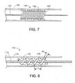
- FIGS. 7 and 8 illustrate other examples of implantable medical endoprosthesis delivery systems.
- An implantable medical endoprosthesis delivery system 150 illustrated in FIG. 5 , has a delivery wire 154 within catheter 156, and a stent 152 disposed between the delivery wire 154 and the catheter 156.
- Windings 158 are disposed on the delivery wire 154 between the delivery wire 154 and the stent 152.
- the windings may be formed of a single strand of winding material, or optionally may be formed of multiple strands of winding material, for example, two, three or more strands of winding material.
- the windings 158 may be formed from a winding material including a resilient material, e.g., a polymer, for example, ElastEonTM, poly-(ether block amide), (e.g., PEBAX ® ) or SIBS.
- the windings may be formed from an elastomeric material, e.g., a material having a durometer of at from about 65A to about 55D.
- the windings may extend substantially along the full length of the endoprosthesis, or may extend along a portion of the endoprosthesis. Multiple sections of windings may be included, e.g., two, three or more sections each supporting a portion of the endoprosthesis.
- the windings 158 are sized to provide a windings diameter sufficient to apply a radial force to the stent 152 so that the stent 152 forms a friction fit with the catheter 156 to retain the stent 152 in a substantially motionless position relative to the delivery wire 154 when the catheter 156 is moved proximally or distally and/or when the delivery wire 154 is moved proximally or distally.
- the windings may form a mechanical grip with the struts of the stent, whereby the struts arc at least partially disposed within the spaces between the windings.
- the windings may in certain examples have an average width (e.g., diameter, when the windings arc cylindrical) of no less than about 3 ⁇ m (e.g., no less than about 50 ⁇ m, no less than about 100 ⁇ m, no less than about 150 ⁇ m, no less than about 200 ⁇ m, no less than about 250 ⁇ m, no less than about 300 ⁇ m, no less than about 350 ⁇ m, no less than about 400 ⁇ m, no less than about 450 ⁇ m, no less than about 500 ⁇ m, no less than about 550 ⁇ m, no less than about 600 ⁇ m, or no less than about 650 ⁇ m) and/or no more than about 700 ⁇ m (e.g., no more than about 650 ⁇ m, no more than about 600 ⁇ m, no more than about 550 ⁇ m, no more than about 500 ⁇ m, no more than about 450 ⁇ m, no more than about 400 ⁇ m, no more than about 350 ⁇ m, no more than about 3
- the windings may in certain embodiments have an average pitch (the length, measured longitudinally, of one full turn of the windings around the delivery wire) of no more than about 10 mm (e.g., no more than about 1 mm, no more than about 0.1 mm. or no more than about 0.05 mm) and/or no less than about 0.025 mm (e.g., no less than about 0.05 mm, no less than about 0.1 mm, or no less than about 1 mm).
- the windings may be placed on the delivery wire such that they are spaced apart from each other, which may impart greater flexibility to the delivery system. For example as illustrated in FIG.
- the ratio of an average pitch p of the windings to an average width w of the windings may be at least about 2 (e.g., at least about 2.5, at least about 3, at least about 3.5, at least about 4, at least about 4.5), and may be at most about 5 (e.g., at most about 4.5, at most about 4, at most about 3.5, at most about 3, at most about 2.5), and may be between about 2 and about 5 (e.g., between about 2.5 and about 4.5, between about 3 and about 4).
- the windings in certain examples extend for an overall length of no more than about 35 mm (e.g., no more than about 30 mm, no more than about 25 mm, or no more than about 20 mm) and/or no less than about 15 mm (e.g., no less than about 20 mm, no less than about 25 mm, or no less than about 30 mm).
- multiple sections of windings can be employed. Where multiple sections of winding are included, each section may have the same or different winding pitch, winding width, and/or ratio of the average pitch to the average width of the windings.
- FIG. 9A shows a delivery wire 200 (e.g., a guidewire) which includes a wire 202 having a first portion 204, a second portion 206, and a third portion 208 disposed between the first and second portions 204 and 206, respectively.
- Windings 210 are disposed on the first portion 204 and the second portion 206 but the third portion 208 has no windings disposed thereupon.
- the windings 210 are typically formed of a material that is different from the material that forms the wire 202.
- windings 210 may be any suitable material for achieving the desired stiffness/flexibility of the delivery wire, and may include, for example, metals, metal oxides, polymers, or plastics.
- the windings 210 are generally sized to provide stent-contacting surfaces 214 that contact both ends of stent 212 so that the stent 212 is retained in a substantially motionless position relative to the delivery wire 200 when the catheter 216 is moved proximally or distally and/or when the delivery wire 200 is moved proximally or distally.
- the windings may have a diameter of no less than about 0.02 mm (e.g., no less than about 0.025 mm, no less than about 0.03 mm, no less than about 0.05 mm, or no less than about 1 mm) and/or no more than about 1.5 mm (e.g., no more than about 1 mm, no more than about 0.05 mm, no more than about 0.03 mm, no more than about 0.025 mm, or no more than about 0.02 mm).
- no less than about 0.02 mm e.g., no less than about 0.025 mm, no less than about 0.03 mm, no less than about 0.05 mm, or no less than about 1 mm
- 1.5 mm e.g., no more than about 1 mm, no more than about 0.05 mm, no more than about 0.03 mm, no more than about 0.025 mm, or no more than about 0.02 mm.
- This provides for delivery wires having an overall diameter, inclusive of the windings, of no less than about 0.1 mm (e.g., no less than about 0.2 mm, no less than about 0.3 mm, no less than about 0.4 mm, no less than about 0.5 mm, no less than about 0.6 mm, no less than about 0.7 mm, no less than about 0.8 mm, or no less than about 0.9 mm) and/or no more than about 1.0 mm (e.g., no more than about 0.9 mm, no more than about 0.8 mm, no more than about 0.7 mm, no more than about 0.6 mm, no more than about 0.5 mm, no more than about 0.4 mm, no more than about 0.3 mm, no more than about 0.2 mm, or no more than about 0.1 mm).
- no less than about 0.1 mm e.g., no less than about 0.2 mm, no less than about 0.3 mm, no less than about 0.4 mm, no less than about 0.5
- the third portion 208 is generally configured to be at least as long as or slightly longer than the implantable endoprosthesis that is to be disposed around the third portion 208.
- the third portion has a length of at least about 0.5 cm (e.g., at least about 1 cm, at least about 2 cm, at least about 3 cm, at least about 4 cm, at least about 5 cm, at least about 6 cm, at least about 8 cm, or at least about 10 cm) and or no more than about 15 cm (e.g., no more than about 10 cm, no more than about 8 cm, no more than about 6 cm, no more than about 5 cm, no more than about 4 cm, no more than about 3 cm, no more than about 2 cm, or no more than about 1 cm).
- FIG. 9B An implantable medical endoprosthesis delivery system 220 including the delivery wire 200 is illustrated in FIG. 9B .
- a stent 212 is disposed between the first portion 204 of the delivery wire 200 and a catheter 216.
- the windings 210 each have a stent-contacting surface 214 disposed on the end of the windings 210 that face the third section 208 of the delivery wire 200.
- the third portion 208 is sized to permit rotation or torque of the delivery wire 200 while applying substantially no torque to the stent 212.
- the delivery wire may further include a proximal bumper, a distal tip or bumper, or both, on the first and or second portions and typically at the edge of the proximal and distal portions nearest the intermediate portion.
- a proximal bumper, a distal tip or bumper, or both may contact the stent in lieu of a stent-contacting surface of the windings, and would serve the same purpose, namely to hold the stent substantially motionless (in a proximal or distal direction) relative to the delivery wire.
- the third portion of the delivery wire may have windings disposed thereupon, provided that the diameter of the third portion, inclusive of the optional windings, remains small enough to permit the delivery wire to be torqued without imparting torque to the stent.
- Such a configuration may be desirable where additional stiffness is desired in the delivery wire, for example, where the endoprosthesis is particularly long (e.g. at least 25 mm long, at least 30 mm long, at least 35 mm long, at least 40 mm long, or at least 45 mm long).
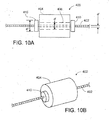
- FIGS. 10A and 10B illustrate a delivery wire 400 (e.g., a guidewire) including a wire 402 having a member 404 (e.g., a seating member or a bumper) disposed thereon, in which the wire 402 can be rotated without causing the member 404 to rotate.
- the member 404 has a lumen 406 through which the wire 402 passes.
- the lumen 406 has a diameter d' that is large enough to allow the wire 402 to rotate within the lumen .406 without applying substantial amounts of (e.g., without applying any) torque to the member 404 (e.g., d' is larger than a diameter d" of the wire 402).
- a pair of sub-bumpers 410 are attached (e.g., adhered) to the wire 402 at positions proximal and distal the member 404.
- the sub-bumpers 410 each have a diameter d'" that is larger than the diameter d' of the lumen 406 in member 404, such that the sub-bumpers can prevent the member 404 from moving proximally or distally along the wire 402 beyond either of the sub-bumpers 410. In this fashion, the member 404 is retained laterally at a single position on wire 402, but is not subject to torque when wire 402 is rotated (e.g., to steer wire 402 through a body lumen).
- the sub-bumpers 410 are attached to the wire 402 such that the sub-bumpers 410 move laterally and rotationally with the wire 402.
- the diameter d'" of the sub-bumpers 410 is smaller than an outer diameter of the member 404.
- FIG. 11 illustrates an implantable medical endoprosthesis delivery system 420 that includes bumpers stent seating members that are not subject to torque when the delivery wire is rotated.
- the system 420 includes a pair of bumpers 424, each having a lumen 426 through which a wire 422 passes, the lumen 426 having a diameter larger than the diameter of the wire 422.
- the bumpers are held in place laterally by two pairs of sub-bumpers 430, each attached to the wire 422 such that they move laterally and rotationally along with the wire 422.
- the sub-bumpers 430 have a diameter larger than the diameter of the lumen 426 of the bumpers 424.
- the bumpers 424 are spaced apart from one another such that a stent 450 can be located between the bumpers 424.
- the stent 450 and the delivery wire 422 are contained in a catheter 428, which constrains the stent 450 from expanding into its fully-expanded state.
- a seating member 438 is disposed between the wire 422 and the stent 450.
- the seating member 438 has a lumen 440 through which the wire 422 passes, the lumen 440 having a diameter larger than the diameter of the wire 422.
- the seating member 438 is held in place laterally by two pairs of sub-bumpers 442, each attached to the wire 422 such that they move laterally and rotationally along with the wire 422.
- the sub-bumpers 442 have a diameter larger than the diameter of the lumen 440 of the seating member 438.
- the seating member 438 has a diameter of sufficient size such that an outer (seating) surface 444 on the seating member 442 contacts the stent 450 while the stent 450 is disposed within the catheter 428.
- the bumpers 424 each have a diameter such that the bumper can contact a proximal edge 452 or a distal edge 454 of the stent 450.
- Each of the sub-bumpers 430 and 442 arc sized to be larger than the lumen of the member (bumper 424 or seating member 438) that they abut while being small enough to avoid subjecting either the stent 450 or the catheter 428 to torque upon rotation of the wire 422.
- an implantable medical endoprosthesis may be delivered using a delivery catheter rather than a delivery wire.
- an implantable medical endoprosthesis delivery system 50 includes a delivery catheter 54 within outer catheter 56, and a stent 52 disposed between the delivery catheter 54 and the outer catheter 56.
- a first seating member 58 and second seating member 60 arc disposed on the delivery catheter 54 between the delivery catheter 54 and the stent 52.
- the first and second seating members 58 and 60 each have a diameter such that seating surfaces 62 on each of the first and second members 58 and 60 contacts the stent 52.
- the first and second seating members 58 and 60 are configured such that, when the outer catheter 56 moves proximally or distally with respect to the delivery catheter 54, the stent 52 remains substantially stationary with respect to the delivery catheter 54, while when the delivery catheter 54 moves proximally or distally, the stent 52 remains substantially stationary with respect to the delivery catheter 54.
- the first and second seating members 58 and 60 may be made of any of the materials disclosed above, and may include seating surfaces in accordance with those described above.
- a proximal bumper 66 is disposed on the delivery catheter 54 proximal to the stent 52 and is configured to substantially prevent proximal movement of the stent 52 when the outer catheter 56 is moved proximally.
- the proximal bumper 66 may also serve to help in pushing the stent 52 through the outer catheter 56 where such is desired.
- a bullet-shaped tip 68 is connected to a distal end 55 of the delivery catheter 54 distal of the stent 52 and is configured to substantially prevent distal movement of the stent 52 when the outer catheter 56 is moved distally.
- the bullet-shaped tip 68 includes a tip lumen 69 extending longitudinally therethrough to form, in conjunction with a lumen 53 in delivery catheter 54, a lumen, e.g., through which a guidewire (not here illustrated) can extend.
- a seating member may extend distally beyond the distal end of the delivery device and itself form a tip, e.g., a bullet shaped tip.
- the delivery wire can in certain embodiments comprise a metal, an alloy (e.g., a stainless steel or Nitinol), or a polymer (e.g., a plastic).
- a metal e.g., a stainless steel or Nitinol
- a polymer e.g., a plastic
- the delivery member can be formed of a tube, e.g., a tube having a spiral tube, attached (e.g., by adhesive or by weld) to the outside of the tube.
- the delivery member can be a slotted hypotube, a rigid or semirigid tube having slots cut into it (e.g., by mechanical cutting or laser ablation).
- Such a delivery device can include an inner lumen while maintaining more flexibility than an unslotted tube.
- the catheter or sheath in which the endoprosthesis is contained may be a microcatheter, e.g., the catheter may have a diameter of not more than about 5 french (e.g., not more than about 4 french, not more than about 3.5 french, not more than about 3 french, not more than about 2.5 french, not more than about 2.3 french, not more than about 2 french).
- an adhesive may be interposed between the delivery wire or catheter and the seating members, coatings, and/or windings to ensure that the seating device travels with the delivery device.
- a seating member can be a balloon that could be at least partially inflated to achieve a friction fit between itself and the endoprosthesis.
- a balloon could optionally remain uninflated unless retraction of a partially-deployed endoprosthesis was desired, at which point it could be at least partially inflated to achieve a friction fit.
- the endoprostheses, delivery wires, catheters and/or guidewires may include one or more radiopaque materials, for example, one or more bands of radiopaque materials.
- any of the seating components can comprise a resilient and/or deformable material such that the endoprosthesis can press into it, forming a releasable mechanical grip with the seating member.
- the seating component may have a durometer of no more than 55D (e.g., no more than 65A).
- Exemplary resilient materials include, for example, ElastEonTM, SIBS, or poly-(ether block amide), (e.g., PEBAX ® ).
- the seating surface may have a tacky consistency to which the endoprosthesis adheres, provided that substantially no material transfers from the seating surface to the stent.
- exemplary tacky seating surfaces include ElastEonTM, SIBS, or poly-(ether block amide), (e.g., PEBAX ® ).
- embodiments While certain embodiments have been shown and/or described without a distal tip or a proximal bumper, embodiments generally can have a distal tip (e.g., a bullet-shaped distal tip) and/or a proximal bumper.
- a distal tip e.g., a bullet-shaped distal tip
- a proximal bumper e.g., a proximal bumper
Description
- This disclosure generally relates to implantable medical endoprosthesis delivery systems and related components, as well as related methods.
- Systems arc known for delivering medical devices, such as stents, into a body lumen. Often, such systems include a proximal portion that remains outside the body during use and a distal portion that is disposed within the body during use. The proximal portion typically includes a handle that is held by an operator of the system (e.g., a physician) during use, and the distal portion can include an outer member surrounding an inner member with a stent positioned therebetween. Generally, the operator of the system positions the distal portion within the 9lumen at a desired location (e.g., so that the stent is adjacent an occlusion). The operator can then retract the outer member to allow the stent to engage the occlusion/lumen wall. Thereafter, the operator removes the distal portion of the system from the lumen.
-
US 2006/0058865 A1 ,WO 99/47075 WO 02/056798 A WO 97/48343 - The invention is directed to an implantable medical endoprosthesis delivery system according to claim 1. Embodiments of the invention are provided in the dependent claims.
- Embodiments can include one or more of the following advantages.
- In some embodiments, the endoprosthesis delivery systems may enable the prosthesis to be partially deployed and or partially expanded and then retracted into the catheter to be repositioned and or removed.
- In certain embodiments, the outer diameter of the system may be reduced, for example, to a microcatheter size to enable delivery and deployment of endoluminal devices to lumens having a small diameter.
- In some embodiments, the delivery system may have enhanced flexibility for traveling through tortuous pathways in a subject's body.
- Other features and advantages arc apparent from the description, drawings and claims.
-
-
FIG. 1 is a partial cross-sectional view of an embodiment of an implantable medical endoprosthesis delivery system. -
FIGS. 2A-C are diagrams of an embodiment of a method. -
FIGS. 3A-C arc diagrams of an embodiment of a method. -
FIGS. 4A-C arc diagrams of an embodiment of a method. -
FIGS. 5A-C are diagrams of an embodiment of a method. -
FIG. 6 is a partial cross-sectional view of an implantable medical endoprosthesis delivery system that is not part of the invention. -
FIG. 7 is a partial cross-sectional view of an implantable medical endoprosthesis delivery system that is not part of the invention. -
FIG. 8 is a partial cross-sectional view of an implantable medical endoprosthesis delivery system that is not part of the invention. -
FIG. 9A is an example of a guidewire that is not part of the invention. -
FIG. 9B is an example of an implantable medical endoprosthesis delivery system including the guidewire ofFIG. 9A . -
FIG. 10A is a cross-sectional view of an example of a bumper on a delivery wire. -
FIG. 10B is a perspective view of the example ofFIG. 11A . -
FIG. 11 is a partial cross-sectional view of an implantable medical endoprosthesis delivery system that is not part of the invention. -
FIG. 12 is a partial cross-sectional view of an embodiment of an implantable medical endoprosthesis delivery system. - Like reference symbols in the various drawings indicate like elements.
-
FIG. 1 shows an implantable medicalendoprosthesis delivery system 10 including a delivery wire 14 (e.g., a guide wire) within acatheter 16, and astent 12 disposed between thedelivery wire 14 and thecatheter 16. Stent 12 is typically a self-expanding stent, and is typically contained in thecatheter 16, which constrainsstent 12 from expanding into its fully-expanded state. Afirst seating member 18 and asecond seating member 20 are disposed on thedelivery wire 14 between thedelivery wire 14 and thestent 12. The first andsecond seating members seating surfaces 22 on each of the first andsecond members stent 12 while thestent 12 is disposed within thecatheter 16. Theseating members stent 12 and thecatheter 16, such that, when the stent is disposed on theseating members catheter 16, thestent 12 will preferentially remain disposed on theseating members catheter 16 andseating members stent 12 and theseating members seating surfaces 22 may have a coefficient of friction higher than that of the inner surface of thecatheter 16. In certain embodiments, theseating members seating surfaces 22 may be formed of a material which is at least partially deformable, for example, a soft, tacky, resilient, or elastomeric material, for example, a material having a durometer of from about 55A to about 100A (e.g., from about 60A to about 90A, from about 65A to about 85A, or from about 70A to about 80A) and/or from about 15D to about 55D (e.g., from about 20D to about 50D, from about 25D to about 45D, or from about 30D to about 40D). The durometer, or hardness, is measured in accordance with ASTM 2240. In some embodiments, the stent is at least slightly pressed into the at least partially deformable seating member and/or seating surface. Exemplary materials include rubber, synthetic rubber, latex, polyurethane/silicone combinations such as, for example, Elast-Eon™ polymers by AorTech, and other polymers such as, for example, [poly(styrene-b-. isobutylene-b-styrene)] ("SIBS"), or poly-(ether block amide), (e.g., PEBAX®). - In certain embodiments, the seating surface may have one or more grooves into which the stent can be at least partially deployed. The
stent 12, as a result of the seating members and/or seating surfaces, remains substantially stationary with respect to thedelivery wire 14 when thecatheter 16 moves proximally or distally with respect to thedelivery wire 14. Likewise, while when thedelivery wire 14 moves proximally or distally, thestent 12 remains substantially stationary with respect to thedelivery wire 14. Exemplary materials for forming theseating members seating surfaces 22 include rubber, synthetic rubber, latex, polyurethane/silicone combinations such as, for example, Elast-Eon™ polymers, and other polymers such as, for example, [poly(styrene-b-. isobutylene-b-styrene)] ("SIBS"), or poly-(ether block amide), (e.g., PEBAX®). Theseating surfaces 22 may be formed of the same or a different material than theseating members seating members - As illustrated in
FIG. 1 , the implantable medicalendoprosthesis delivery system 10 may further include aproximal bumper 26 disposed on thedelivery wire 14 proximal to thestent 12. Theproximal bumper 26 is configured to substantially prevent proximal movement of thestent 12 when thecatheter 16 is moved proximally. Theproximal bumper 26 may also serve to help in pushing thestent 12 through thecatheter 16 where such is desired. A bullet-shaped tip 28 is connected to thedelivery wire 14 distal of thestent 12. Thetip 28 is configured to substantially prevent distal movement of thestent 12 when thecatheter 16 is moved distally and to assist in the delivery of thecatheter 16, preloaded with thestent 12, through body lumens to the position at which thestent 12 is to be deployed. Optionally, thedelivery wire 14 can extend through thetip 28 such that adistal portion 29 of thedelivery wire 14 extends beyond thetip 28 distally, for example, through a lumen (not illustrated) in thetip 28. -
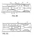
FIGS. 2 and3 illustrate a method utilizing implantable medicalendoprosthesis delivery system 10. In general, implantable medicalendoprosthesis delivery system 10 is used as follows.System 10 is positioned within a body lumen 30 (e.g., an artery) at a desired location, for example, adjacent anocclusion 35. Initially, as seen inFIGS. 2A and3A , thestent 12 is contained in an unexpanded state within thecatheter 16 at adistal end 17 of thecatheter 16. Thecatheter 16 serves to restrain thestent 12 from self-expanding at this point. Thecatheter 16 is withdrawn (moved proximally) as indicated by arrows X inFIGS. 2B and 2C , to expose or uncover adistal portion 12 a of thestent 12. When thedistal portion 12 a of thestent 12 is uncovered (and thereby unrestrained from self-expansion), the distal portion self-expands towards a deployed diameter d , which is the diameter of thestent 12 when expanded in thebody lumen 30. Typically, the deployed diameter d is less than the diameter to which thestent 12 would expand absent thebody lumen 30. In this fashion, thestent 12 can continue to exert radial force, which can help to force open the occlusion and/or to maintain the position of thestent 12 within thebody lumen 30. - At this point, the physician may desire to reposition the stent and/or system within
lumen 30, e.g., to select a more suitable location for the stent or to correct for errors in positioning resulting from the partial deployment of the stent. Optionally, the physician may desire to entirely re-sheath and/or remove the stent (e.g., to replace it with a stent of, for example, a larger or smaller expanded diameter). Re-sheathing of the stent is possible, due at least in part to the presence of thesecond seating member 20. Thecatheter 16 can, as illustrated inFIG. 2C , be advanced (moved distally as indicated by arrows Y ) to re-cover at least some of the expandeddistal portion 12 a of thestent 12 and depose the at least some of the expandeddistal portion 12 a of thestent 12 within thecatheter 16. - Alternatively, as illustrated in
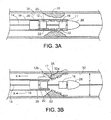
FIG. 3C , thecatheter 16 can be further withdrawn as indicated by arrows Z to expose or uncover the remainingproximal portion 12 b ofstent 12.Stent 12 can expand to the extent that thebody lumen 30 permits once so exposed. -
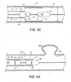
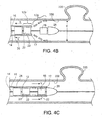
FIGS. 4 and5 illustrate a similar method, utilizing implantable medicalendoprosthesis delivery system 10 to block the opening of ananeurysm 335 and/or strengthen a vessel at the site ofancurysm 335.System 10 is positioned within a body lumen 330 (e.g., an artery) at a desired location, for example,adjacent aneurysm 335. Initially, as seen inFIGS. 4A and5A , thestent 12 is contained in an unexpanded state within thecatheter 16 at adistal end 17 of thecatheter 16. Thecatheter 16 is withdrawn (moved proximally) as indicated by arrows X inFIGS. 4B and5B , to expose or uncover adistal portion 12a of thestent 12. When thedistal portion 12 a of thestent 12 is uncovered (and thereby unrestrained from self-expansion), the distal portion self-expands towards a deployed diameter d , which is the diameter of thestent 12 when expanded in thebody lumen 330. At this point, the physician may desire to reposition the stent and/or system withinlumen 330 or to entirely re-sheath and remove the stent and replace it with a stent of, for example, a larger or smaller expanded diameter. Thecatheter 16 can, as illustrated inFIG. 4C , be advanced (moved distally as indicated by arrows Y ) to re-cover at least some of the expandeddistal portion 12 a of thestent 12 and depose the at least some of the expandeddistal portion 12 a of thestent 12 within thecatheter 16. - Should the physician determine that the
stent 12 is properly positioned withinlumen 330, as illustrated inFIG. 5C ,thecatheter 16 can be further withdrawn as indicated by arrows Z to expose or uncover the remainingproximal portion 12b ofstent 12.Stent 12 can then expand to the extent that thebody lumen 330 permits once so exposed, thereby at least partially occluding theopening 336 to theaneurysm 335. - In the example illustrated in
FIG. 6 , an implantable medicalendoprosthesis delivery system 100 has adelivery wire 114 withincatheter 116, and astent 112 disposed between thedelivery wire 114 and thecatheter 116. Acoating 118 is disposed on the delivery wire 114 (e.g., a guide wire) between thedelivery wire 114 and thestent 112, with acoating surface 122 contacting thestent 112. In general, thecoating surface 122 is formed of a material that presses against or into the stent to force the stent to travel longitudinally, relative to the catheter, with the delivery wire. The coating may in certain embodiments be formed of a liquid or fluid material placed on or applied to the exterior of the wire and allowed to harden on the exterior of the wire, for example, sprayed on, brushed on, shrink-wrapped, and/or hot-dipped. Generally, the thickness of the coating is selected based on the catheter inner diameter, stent thickness, and delivery wire diameter. In some embodiments, the coating has a thickness of no less than about 0.05 mm (e.g., no less than about 0.10 mm, no less than about 0.15 mm, or no less than about 0.20 mm) and/or no more than about 0.25 mm (e.g., no more than about 0.20 mm, no more than about 0.15 mm, or no more than about 0.10 mm). - The coating may in certain embodiments be a sleeve or a cylindrical plug of material having a central bore for receiving the delivery wire. The sleeve or plug grips the delivery wire with sufficient force to ensure that it travels with the delivery wire. The coating may be a polymer coating, for example a thermoplastic coating (e.g., ElastEon™) or may be a rubber, synthetic rubber, SIBS, or poly-(ether block amide) (e.g., PEBAX®). The coating thickness is generally selected such that the coating will contact the endoprosthesis while the prosthesis is disposed within the delivery catheter and may be, for example, no less than about 3 µm thick (e.g., no less than about 50 µm thick, no less than about 100 µm thick, no less than about 150 µm thick, no less than about 200 µm thick, no less than about 250 µm thick, no less than about 300 µm thick, no less than about 350 µm thick, no less than about 400 µm thick, no less than about 450 µm thick, no less than about 500 µm thick, no less than about 550 µm thick, no less than about 600 µm thick, or no less than about 650 µm thick) and/or no more than about 700 µm thick (e.g., no more than about 650 µm thick, no more than about 600 µm thick, no more than about 550 µm thick, no more than about 500 µm thick, no more than about 450 µm thick, no more than about 400 µm thick, no more than about 350 µm thick, no more than about 300 µm thick, no more than about 250 µm thick, no more than about 200 µm thick, no more than about 150 µm thick, no more than about 100 µm thick, or no more than about 50 µm thick). This provides for delivery wire/coating combinations having a diameter of no less than about 0.1 mm (e.g., no less than about 0.2 mm, no less than about 0.4 mm, no less than about 0.6 mm, no less than about 0.8 mm, or no less than about 1 mm) and/or no more than about 1.2 mm (e.g., no more than about I mm, no more than about 0.8 mm, no more than about 0.6 mm, no more than about 0.4 mm, or no more than about 0.2 mm). The
coating 118 and thecoating surface 122 may be formed of the same or of different materials. Thecoating 118 and thecoating surface 122 may be contiguous, whereby the coating surface is formed of the outward-facing surface of the coating. The coating and coating surface arc configured to retain thestent 112 in a substantially motionless position relative to thedelivery wire 114 when thecatheter 116 is moved proximally or distally and/or when thedelivery wire 114 is moved proximally or distally. -
FIGS. 7 and 8 illustrate other examples of implantable medical endoprosthesis delivery systems. An implantable medicalendoprosthesis delivery system 150, illustrated inFIG. 5 , has a delivery wire 154 withincatheter 156, and astent 152 disposed between the delivery wire 154 and thecatheter 156.Windings 158 are disposed on the delivery wire 154 between the delivery wire 154 and thestent 152. The windings may be formed of a single strand of winding material, or optionally may be formed of multiple strands of winding material, for example, two, three or more strands of winding material. Thewindings 158 may be formed from a winding material including a resilient material, e.g., a polymer, for example, ElastEon™, poly-(ether block amide), (e.g., PEBAX®) or SIBS. The windings may be formed from an elastomeric material, e.g., a material having a durometer of at from about 65A to about 55D. The windings may extend substantially along the full length of the endoprosthesis, or may extend along a portion of the endoprosthesis. Multiple sections of windings may be included, e.g., two, three or more sections each supporting a portion of the endoprosthesis. Thewindings 158 are sized to provide a windings diameter sufficient to apply a radial force to thestent 152 so that thestent 152 forms a friction fit with thecatheter 156 to retain thestent 152 in a substantially motionless position relative to the delivery wire 154 when thecatheter 156 is moved proximally or distally and/or when the delivery wire 154 is moved proximally or distally. In certain examples, the windings may form a mechanical grip with the struts of the stent, whereby the struts arc at least partially disposed within the spaces between the windings. - In general, the windings may in certain examples have an average width (e.g., diameter, when the windings arc cylindrical) of no less than about 3 µm (e.g., no less than about 50 µm, no less than about 100 µm, no less than about 150 µm, no less than about 200 µm, no less than about 250 µm, no less than about 300 µm, no less than about 350 µm, no less than about 400 µm, no less than about 450 µm, no less than about 500 µm, no less than about 550 µm, no less than about 600 µm, or no less than about 650 µm) and/or no more than about 700 µm (e.g., no more than about 650 µm, no more than about 600 µm, no more than about 550 µm, no more than about 500 µm, no more than about 450 µm, no more than about 400 µm, no more than about 350 µm, no more than about 300 µm, no more than about 250 µm, no more than about 200 µm, no more than about 150 µm, no more than about 100 µm, or no more than about 50 µm). The windings may in certain embodiments have an average pitch (the length, measured longitudinally, of one full turn of the windings around the delivery wire) of no more than about 10 mm (e.g., no more than about 1 mm, no more than about 0.1 mm. or no more than about 0.05 mm) and/or no less than about 0.025 mm (e.g., no less than about 0.05 mm, no less than about 0.1 mm, or no less than about 1 mm). In certain embodiments, the windings may be placed on the delivery wire such that they are spaced apart from each other, which may impart greater flexibility to the delivery system. For example as illustrated in
FIG. 8 , the ratio of an average pitch p of the windings to an average width w of the windings may be at least about 2 (e.g., at least about 2.5, at least about 3, at least about 3.5, at least about 4, at least about 4.5), and may be at most about 5 (e.g., at most about 4.5, at most about 4, at most about 3.5, at most about 3, at most about 2.5), and may be between about 2 and about 5 (e.g., between about 2.5 and about 4.5, between about 3 and about 4). - The windings in certain examples extend for an overall length of no more than about 35 mm (e.g., no more than about 30 mm, no more than about 25 mm, or no more than about 20 mm) and/or no less than about 15 mm (e.g., no less than about 20 mm, no less than about 25 mm, or no less than about 30 mm). In some examples, multiple sections of windings can be employed. Where multiple sections of winding are included, each section may have the same or different winding pitch, winding width, and/or ratio of the average pitch to the average width of the windings.
-
FIG. 9A shows a delivery wire 200 (e.g., a guidewire) which includes awire 202 having afirst portion 204, asecond portion 206, and athird portion 208 disposed between the first andsecond portions Windings 210 are disposed on thefirst portion 204 and thesecond portion 206 but thethird portion 208 has no windings disposed thereupon. Thewindings 210 are typically formed of a material that is different from the material that forms thewire 202. Generally,windings 210 may be any suitable material for achieving the desired stiffness/flexibility of the delivery wire, and may include, for example, metals, metal oxides, polymers, or plastics. Thewindings 210 are generally sized to provide stent-contactingsurfaces 214 that contact both ends ofstent 212 so that thestent 212 is retained in a substantially motionless position relative to thedelivery wire 200 when thecatheter 216 is moved proximally or distally and/or when thedelivery wire 200 is moved proximally or distally. In certain embodiments, the windings may have a diameter of no less than about 0.02 mm (e.g., no less than about 0.025 mm, no less than about 0.03 mm, no less than about 0.05 mm, or no less than about 1 mm) and/or no more than about 1.5 mm (e.g., no more than about 1 mm, no more than about 0.05 mm, no more than about 0.03 mm, no more than about 0.025 mm, or no more than about 0.02 mm). This provides for delivery wires having an overall diameter, inclusive of the windings, of no less than about 0.1 mm (e.g., no less than about 0.2 mm, no less than about 0.3 mm, no less than about 0.4 mm, no less than about 0.5 mm, no less than about 0.6 mm, no less than about 0.7 mm, no less than about 0.8 mm, or no less than about 0.9 mm) and/or no more than about 1.0 mm (e.g., no more than about 0.9 mm, no more than about 0.8 mm, no more than about 0.7 mm, no more than about 0.6 mm, no more than about 0.5 mm, no more than about 0.4 mm, no more than about 0.3 mm, no more than about 0.2 mm, or no more than about 0.1 mm). Thethird portion 208 is generally configured to be at least as long as or slightly longer than the implantable endoprosthesis that is to be disposed around thethird portion 208. For example, in some embodiments, the third portion has a length of at least about 0.5 cm (e.g., at least about 1 cm, at least about 2 cm, at least about 3 cm, at least about 4 cm, at least about 5 cm, at least about 6 cm, at least about 8 cm, or at least about 10 cm) and or no more than about 15 cm (e.g., no more than about 10 cm, no more than about 8 cm, no more than about 6 cm, no more than about 5 cm, no more than about 4 cm, no more than about 3 cm, no more than about 2 cm, or no more than about 1 cm). - An implantable medical
endoprosthesis delivery system 220 including thedelivery wire 200 is illustrated inFIG. 9B . Astent 212 is disposed between thefirst portion 204 of thedelivery wire 200 and acatheter 216. Thewindings 210 each have a stent-contactingsurface 214 disposed on the end of thewindings 210 that face thethird section 208 of thedelivery wire 200. Thethird portion 208 is sized to permit rotation or torque of thedelivery wire 200 while applying substantially no torque to thestent 212. - In some examples, the delivery wire may further include a proximal bumper, a distal tip or bumper, or both, on the first and or second portions and typically at the edge of the proximal and distal portions nearest the intermediate portion. Such bumper or bumpers may contact the stent in lieu of a stent-contacting surface of the windings, and would serve the same purpose, namely to hold the stent substantially motionless (in a proximal or distal direction) relative to the delivery wire. In some embodiments, the third portion of the delivery wire may have windings disposed thereupon, provided that the diameter of the third portion, inclusive of the optional windings, remains small enough to permit the delivery wire to be torqued without imparting torque to the stent. Such a configuration may be desirable where additional stiffness is desired in the delivery wire, for example, where the endoprosthesis is particularly long (e.g. at least 25 mm long, at least 30 mm long, at least 35 mm long, at least 40 mm long, or at least 45 mm long).
-
FIGS. 10A and 10B illustrate a delivery wire 400 (e.g., a guidewire) including awire 402 having a member 404 (e.g., a seating member or a bumper) disposed thereon, in which thewire 402 can be rotated without causing themember 404 to rotate. Themember 404 has alumen 406 through which thewire 402 passes. Thelumen 406 has a diameter d' that is large enough to allow thewire 402 to rotate within the lumen .406 without applying substantial amounts of (e.g., without applying any) torque to the member 404 (e.g., d' is larger than a diameter d" of the wire 402). A pair ofsub-bumpers 410 are attached (e.g., adhered) to thewire 402 at positions proximal and distal themember 404. The sub-bumpers 410 each have a diameter d'" that is larger than the diameter d' of thelumen 406 inmember 404, such that the sub-bumpers can prevent themember 404 from moving proximally or distally along thewire 402 beyond either of the sub-bumpers 410. In this fashion, themember 404 is retained laterally at a single position onwire 402, but is not subject to torque whenwire 402 is rotated (e.g., to steerwire 402 through a body lumen). The sub-bumpers 410 are attached to thewire 402 such that thesub-bumpers 410 move laterally and rotationally with thewire 402. The diameter d'" of the sub-bumpers 410 is smaller than an outer diameter of themember 404. -
FIG. 11 illustrates an implantable medicalendoprosthesis delivery system 420 that includes bumpers stent seating members that are not subject to torque when the delivery wire is rotated. Thesystem 420 includes a pair ofbumpers 424, each having alumen 426 through which awire 422 passes, thelumen 426 having a diameter larger than the diameter of thewire 422. The bumpers are held in place laterally by two pairs ofsub-bumpers 430, each attached to thewire 422 such that they move laterally and rotationally along with thewire 422. The sub-bumpers 430 have a diameter larger than the diameter of thelumen 426 of thebumpers 424. Thebumpers 424 are spaced apart from one another such that astent 450 can be located between thebumpers 424. Thestent 450 and thedelivery wire 422 are contained in acatheter 428, which constrains thestent 450 from expanding into its fully-expanded state. - A seating
member 438 is disposed between thewire 422 and thestent 450. The seatingmember 438 has alumen 440 through which thewire 422 passes, thelumen 440 having a diameter larger than the diameter of thewire 422. The seatingmember 438 is held in place laterally by two pairs ofsub-bumpers 442, each attached to thewire 422 such that they move laterally and rotationally along with thewire 422. The sub-bumpers 442 have a diameter larger than the diameter of thelumen 440 of theseating member 438. - The seating
member 438 has a diameter of sufficient size such that an outer (seating)surface 444 on theseating member 442 contacts thestent 450 while thestent 450 is disposed within thecatheter 428. Thebumpers 424 each have a diameter such that the bumper can contact aproximal edge 452 or adistal edge 454 of thestent 450. Each of thesub-bumpers bumper 424 or seating member 438) that they abut while being small enough to avoid subjecting either thestent 450 or thecatheter 428 to torque upon rotation of thewire 422. - In certain examples, an implantable medical endoprosthesis may be delivered using a delivery catheter rather than a delivery wire. One such embodiment is illustrated in
FIG. 12 , in which an implantable medicalendoprosthesis delivery system 50 includes adelivery catheter 54 withinouter catheter 56, and astent 52 disposed between thedelivery catheter 54 and theouter catheter 56. Afirst seating member 58 andsecond seating member 60 arc disposed on thedelivery catheter 54 between thedelivery catheter 54 and thestent 52. The first andsecond seating members second members stent 52. The first andsecond seating members outer catheter 56 moves proximally or distally with respect to thedelivery catheter 54, thestent 52 remains substantially stationary with respect to thedelivery catheter 54, while when thedelivery catheter 54 moves proximally or distally, thestent 52 remains substantially stationary with respect to thedelivery catheter 54. The first andsecond seating members proximal bumper 66 is disposed on thedelivery catheter 54 proximal to thestent 52 and is configured to substantially prevent proximal movement of thestent 52 when theouter catheter 56 is moved proximally. Theproximal bumper 66 may also serve to help in pushing thestent 52 through theouter catheter 56 where such is desired. A bullet-shapedtip 68 is connected to adistal end 55 of thedelivery catheter 54 distal of thestent 52 and is configured to substantially prevent distal movement of thestent 52 when theouter catheter 56 is moved distally. The bullet-shapedtip 68 includes atip lumen 69 extending longitudinally therethrough to form, in conjunction with alumen 53 indelivery catheter 54, a lumen, e.g., through which a guidewire (not here illustrated) can extend. - While certain embodiments have been described, others are possible.
- For example, in certain embodiments, a seating member may extend distally beyond the distal end of the delivery device and itself form a tip, e.g., a bullet shaped tip.
- As another example, the delivery wire can in certain embodiments comprise a metal, an alloy (e.g., a stainless steel or Nitinol), or a polymer (e.g., a plastic).
- As another example, in certain embodiments, the delivery member can be formed of a tube, e.g., a tube having a spiral tube, attached (e.g., by adhesive or by weld) to the outside of the tube. As another example, the delivery member can be a slotted hypotube, a rigid or semirigid tube having slots cut into it (e.g., by mechanical cutting or laser ablation). Such a delivery device can include an inner lumen while maintaining more flexibility than an unslotted tube.
- As another example, in certain embodiments, the catheter or sheath in which the endoprosthesis is contained may be a microcatheter, e.g., the catheter may have a diameter of not more than about 5 french (e.g., not more than about 4 french, not more than about 3.5 french, not more than about 3 french, not more than about 2.5 french, not more than about 2.3 french, not more than about 2 french).
- As another example, in certain embodiments, an adhesive may be interposed between the delivery wire or catheter and the seating members, coatings, and/or windings to ensure that the seating device travels with the delivery device.
- As another example, in certain embodiments, a seating member can be a balloon that could be at least partially inflated to achieve a friction fit between itself and the endoprosthesis. Such a balloon could optionally remain uninflated unless retraction of a partially-deployed endoprosthesis was desired, at which point it could be at least partially inflated to achieve a friction fit.
- As another example, in certain embodiments, the endoprostheses, delivery wires, catheters and/or guidewires may include one or more radiopaque materials, for example, one or more bands of radiopaque materials.
- As another example, in certain embodiments, any of the seating components (seating members, seating surfaces, coatings, wrappings, windings) the seating members can comprise a resilient and/or deformable material such that the endoprosthesis can press into it, forming a releasable mechanical grip with the seating member. For example, the seating component may have a durometer of no more than 55D (e.g., no more than 65A). Exemplary resilient materials include, for example, ElastEon™, SIBS, or poly-(ether block amide), (e.g., PEBAX®).
- As another example, the seating surface may have a tacky consistency to which the endoprosthesis adheres, provided that substantially no material transfers from the seating surface to the stent. Exemplary tacky seating surfaces include ElastEon™, SIBS, or poly-(ether block amide), (e.g., PEBAX®).
- As yet another example, while certain embodiments have been shown and/or described without a distal tip or a proximal bumper, embodiments generally can have a distal tip (e.g., a bullet-shaped distal tip) and/or a proximal bumper.
Claims (12)
- An implantable medical endoprosthesis delivery system (10), comprising:a delivery member (14) in the form of a wire or a slotted hypotube;a sheath (16);an endoprosthesis (12) having a proximal portion (12b) and a distal portion (12a), the endoprosthesis (12) being disposed between the delivery member (14) and the sheath (16); anda second member (18, 20) configured so that:when the sheath (16) moves proximally or distally with respect to the delivery member (14), the endoprosthesis (12) remains substantially stationary in a longitudinal direction with respect to the delivery member (14); andwhen the delivery member (14) moves proximally or distally, the endoprosthesis (12) remains substantially stationary with respect to the delivery member (14);characterized in thatthe second member comprises:a first seating member (18) disposed between the delivery member (14) and the endoprosthesis distal portion (12a); anda second seating member (20) disposed between the delivery member (14) and the endoprosthesis proximal portion (12b).
- The system (10) of claim 1, wherein the first and second seating members (18, 20) each have a diameter such that seating surfaces (22) on each of the first and second seating members (18, 20) contacts the endoprosthesis (12).
- The system (10) of claim 2, wherein the seating surfaces (22) are formed of a material that is at least partially deformable, the material preferably having a durometer of from 55A to 100A, more preferably from 60A to 90A, even more preferably from 65A to 85A.
- The system (10) of claim 3, wherein the endoprosthesis (12) is at least slightly pressed into the at least partially deformable seating surfaces (22).
- The system (10) of claim 2, wherein the seating surfaces (22) comprises one or more grooves into which the endoprosthesis (12) can be at least partially deployed.
- The system (10) of any one of claims 1 to 5, wherein the delivery member (14) is in the form of a slotted hypotube, the hypotube being disposed over a guidewire.
- The system (10) of any one of claims 1 to 6, wherein the endoprosthesis (12) is a self-expanding prosthesis.
- The system (10) of any one of claims 1 to 7, wherein the second member (18, 20) is disposed on the delivery member.
- The system (10) of any one of claims 1 to 8, wherein the endoprosthesis (12) includes a radiopaque material.
- The system (10) of any one of claims 1 to 9, further comprising a bumper (26) connected to the delivery member (14), the bumper being proximal to the endoprosthesis (12), and the bumper (26) being configured to substantially prevent proximal movement of the endoprosthesis (12) when the sheath (16) is moved proximally.
- The system (10) of any one of claims 1 to 10, further comprising a tip (28) connected to the delivery member (14), the tip being distal to the endoprosthesis (12), and the tip being configured to substantially prevent distal movement of the endoprosthesis (12) when the sheath (16) is moved distally.
- The system of claim 11, wherein the tip (28) is bullet-shaped.
Applications Claiming Priority (2)
| Application Number | Priority Date | Filing Date | Title |
|---|---|---|---|
| US11/395,479 US8092508B2 (en) | 2006-03-30 | 2006-03-30 | Implantable medical endoprosthesis delivery system |
| PCT/US2007/065327 WO2007118005A1 (en) | 2006-03-30 | 2007-03-28 | Implantable medical endoprosthesis delivery system |
Publications (2)
| Publication Number | Publication Date |
|---|---|
| EP2004102A1 EP2004102A1 (en) | 2008-12-24 |
| EP2004102B1 true EP2004102B1 (en) | 2015-10-14 |
Family
ID=38458199
Family Applications (1)
| Application Number | Title | Priority Date | Filing Date |
|---|---|---|---|
| EP07759544.5A Active EP2004102B1 (en) | 2006-03-30 | 2007-03-28 | Implantable medical endoprosthesis delivery system |
Country Status (5)
| Country | Link |
|---|---|
| US (2) | US8092508B2 (en) |
| EP (1) | EP2004102B1 (en) |
| JP (1) | JP2009532115A (en) |
| ES (1) | ES2558845T3 (en) |
| WO (1) | WO2007118005A1 (en) |
Families Citing this family (109)
| Publication number | Priority date | Publication date | Assignee | Title |
|---|---|---|---|---|
| US7018401B1 (en) | 1999-02-01 | 2006-03-28 | Board Of Regents, The University Of Texas System | Woven intravascular devices and methods for making the same and apparatus for delivery of the same |
| US6866679B2 (en) | 2002-03-12 | 2005-03-15 | Ev3 Inc. | Everting stent and stent delivery system |
| WO2010120926A1 (en) | 2004-05-25 | 2010-10-21 | Chestnut Medical Technologies, Inc. | Vascular stenting for aneurysms |
| US8628564B2 (en) | 2004-05-25 | 2014-01-14 | Covidien Lp | Methods and apparatus for luminal stenting |
| US20060206200A1 (en) | 2004-05-25 | 2006-09-14 | Chestnut Medical Technologies, Inc. | Flexible vascular occluding device |
| JP2008502378A (en) | 2004-05-25 | 2008-01-31 | チェストナット メディカル テクノロジーズ インコーポレイテッド | Flexible vascular closure device |
| WO2007100556A1 (en) | 2006-02-22 | 2007-09-07 | Ev3 Inc. | Embolic protection systems having radiopaque filter mesh |
| MX2009004292A (en) | 2006-10-22 | 2009-08-12 | Idev Technologies Inc | Devices and methods for stent advancement. |
| EP3329882B1 (en) | 2006-10-22 | 2023-09-20 | IDEV Technologies, INC. | Methods for securing strand ends and the resulting devices |
| US9034007B2 (en) * | 2007-09-21 | 2015-05-19 | Insera Therapeutics, Inc. | Distal embolic protection devices with a variable thickness microguidewire and methods for their use |
| US20100256600A1 (en) * | 2009-04-04 | 2010-10-07 | Ferrera David A | Neurovascular otw pta balloon catheter and delivery system |
| EP2072065A1 (en) * | 2007-12-21 | 2009-06-24 | Abbott Laboratories Vascular Enterprises Limited | Strengthening textures in medical devices |
| EP2095795A1 (en) * | 2007-12-21 | 2009-09-02 | Abbott Laboratories Vascular Enterprises Limited | Double layered balloons in medical devices |
| EP2633823B1 (en) | 2008-04-21 | 2016-06-01 | Covidien LP | Braid-ball embolic devices and delivery systems |
| US8992591B2 (en) * | 2008-05-07 | 2015-03-31 | Cook Medical Technologies Llc | Delivery system with low longitudinal compressibility |
| US9675482B2 (en) | 2008-05-13 | 2017-06-13 | Covidien Lp | Braid implant delivery systems |
| US9750625B2 (en) | 2008-06-11 | 2017-09-05 | C.R. Bard, Inc. | Catheter delivery device |
| GB0810749D0 (en) | 2008-06-11 | 2008-07-16 | Angiomed Ag | Catherter delivery device |
| EP2293838B1 (en) | 2008-07-01 | 2012-08-08 | Endologix, Inc. | Catheter system |
| US20120310321A1 (en) * | 2009-10-05 | 2012-12-06 | Bradley Beach | Reconstrainable stent delivery system |
| US9149376B2 (en) * | 2008-10-06 | 2015-10-06 | Cordis Corporation | Reconstrainable stent delivery system |
| US20100274276A1 (en) * | 2009-04-22 | 2010-10-28 | Ricky Chow | Aneurysm treatment system, device and method |
| US9468442B2 (en) | 2010-01-28 | 2016-10-18 | Covidien Lp | Vascular remodeling device |
| EP2545887B1 (en) * | 2010-03-30 | 2016-08-10 | Terumo Kabushiki Kaisha | Stent delivery system |
| US9023095B2 (en) | 2010-05-27 | 2015-05-05 | Idev Technologies, Inc. | Stent delivery system with pusher assembly |
| WO2012023980A1 (en) | 2010-08-17 | 2012-02-23 | St. Jude Medical, Inc. | Sleeve for facilitating movement of a transfemoral catheter |
| BR112013006302A2 (en) | 2010-09-17 | 2016-06-07 | St Jude Medical Cardiology Div | placement device for a collapsible prosthetic heart valve, and method for placing a collapsible prosthetic heart valve |
| US9414944B2 (en) * | 2010-11-11 | 2016-08-16 | W. L. Gore & Associates, Inc. | Deployment sleeve shortening mechanism |
| CN103442653B (en) | 2011-02-11 | 2016-06-01 | 柯惠有限合伙公司 | Two benches launches aneurysma embolization device |
| WO2012118901A1 (en) | 2011-03-01 | 2012-09-07 | Endologix, Inc. | Catheter system and methods of using same |
| US8831741B2 (en) * | 2011-03-14 | 2014-09-09 | Medtronic Vascular, Inc. | Catheter with deflectable cap |
| WO2012134990A1 (en) | 2011-03-25 | 2012-10-04 | Tyco Healthcare Group Lp | Vascular remodeling device |
| EP2736450A1 (en) | 2011-07-28 | 2014-06-04 | St. Jude Medical, Inc. | Expandable radiopaque marker for transcatheter aortic valve implantation |
| WO2013049448A1 (en) | 2011-09-29 | 2013-04-04 | Covidien Lp | Vascular remodeling device |
| US10028854B2 (en) | 2012-02-02 | 2018-07-24 | Covidien Lp | Stent retaining systems |
| WO2013119332A2 (en) | 2012-02-09 | 2013-08-15 | Stout Medical Group, L.P. | Embolic device and methods of use |
| EP2628470B1 (en) | 2012-02-16 | 2020-11-25 | Biotronik AG | Release device for releasing a medical implant from a catheter and catheter having a release device and method for clamping an implant therein |
| US20130226278A1 (en) | 2012-02-23 | 2013-08-29 | Tyco Healthcare Group Lp | Methods and apparatus for luminal stenting |
| US9072624B2 (en) | 2012-02-23 | 2015-07-07 | Covidien Lp | Luminal stenting |
| US9078659B2 (en) | 2012-04-23 | 2015-07-14 | Covidien Lp | Delivery system with hooks for resheathability |
| US9480561B2 (en) | 2012-06-26 | 2016-11-01 | St. Jude Medical, Cardiology Division, Inc. | Apparatus and method for aortic protection and TAVI planar alignment |
| US9918837B2 (en) | 2012-06-29 | 2018-03-20 | St. Jude Medical, Cardiology Division, Inc. | System to assist in the release of a collapsible stent from a delivery device |
| US9724222B2 (en) | 2012-07-20 | 2017-08-08 | Covidien Lp | Resheathable stent delivery system |
| JP6057584B2 (en) * | 2012-07-24 | 2017-01-11 | 株式会社カネカ | Self-expanding stent delivery system and manufacturing method thereof |
| US9114001B2 (en) | 2012-10-30 | 2015-08-25 | Covidien Lp | Systems for attaining a predetermined porosity of a vascular device |
| US9452070B2 (en) | 2012-10-31 | 2016-09-27 | Covidien Lp | Methods and systems for increasing a density of a region of a vascular device |
| US9314248B2 (en) | 2012-11-06 | 2016-04-19 | Covidien Lp | Multi-pivot thrombectomy device |
| US9943427B2 (en) | 2012-11-06 | 2018-04-17 | Covidien Lp | Shaped occluding devices and methods of using the same |
| US9295571B2 (en) * | 2013-01-17 | 2016-03-29 | Covidien Lp | Methods and apparatus for luminal stenting |
| US9157174B2 (en) | 2013-02-05 | 2015-10-13 | Covidien Lp | Vascular device for aneurysm treatment and providing blood flow into a perforator vessel |
| US10561509B2 (en) * | 2013-03-13 | 2020-02-18 | DePuy Synthes Products, Inc. | Braided stent with expansion ring and method of delivery |
| US10603157B2 (en) | 2013-03-13 | 2020-03-31 | DePuy Synthes Products, Inc. | Braid implant delivery and retraction device with distal engagement |
| US9463105B2 (en) * | 2013-03-14 | 2016-10-11 | Covidien Lp | Methods and apparatus for luminal stenting |
| US9855160B2 (en) * | 2013-03-14 | 2018-01-02 | W. L. Gore & Associates, Inc. | Endoprosthesis delivery systems with deployment aids |
| CN108433769B (en) | 2013-03-15 | 2021-06-08 | 柯惠有限合伙公司 | Occlusion device |
| US8715314B1 (en) | 2013-03-15 | 2014-05-06 | Insera Therapeutics, Inc. | Vascular treatment measurement methods |
| SG10201709513PA (en) | 2013-03-15 | 2018-01-30 | Insera Therapeutics Inc | Vascular treatment devices and methods |
| US8690907B1 (en) | 2013-03-15 | 2014-04-08 | Insera Therapeutics, Inc. | Vascular treatment methods |
| US8679150B1 (en) | 2013-03-15 | 2014-03-25 | Insera Therapeutics, Inc. | Shape-set textile structure based mechanical thrombectomy methods |
| CN105530986A (en) | 2013-05-08 | 2016-04-27 | 埃姆博尔克斯公司 | Device and methods for transvascular tumor embolization with integrated flow regulation |
| US9844383B2 (en) | 2013-05-08 | 2017-12-19 | Embolx, Inc. | Devices and methods for low pressure tumor embolization |
| JP6755794B2 (en) | 2013-07-19 | 2020-09-16 | プロ−デツクス・インコーポレイテツド | Torque limit driver |
| US10130500B2 (en) | 2013-07-25 | 2018-11-20 | Covidien Lp | Methods and apparatus for luminal stenting |
| US9474639B2 (en) | 2013-08-27 | 2016-10-25 | Covidien Lp | Delivery of medical devices |
| US9782186B2 (en) | 2013-08-27 | 2017-10-10 | Covidien Lp | Vascular intervention system |
| US9060777B1 (en) | 2014-05-28 | 2015-06-23 | Tw Medical Technologies, Llc | Vaso-occlusive devices and methods of use |
| CN106604696A (en) | 2014-05-28 | 2017-04-26 | 斯瑞克欧洲控股有限责任公司 | Vaso-occlusive devices and methods of use |
| US10206796B2 (en) | 2014-08-27 | 2019-02-19 | DePuy Synthes Products, Inc. | Multi-strand implant with enhanced radiopacity |
| US9375336B1 (en) * | 2015-01-29 | 2016-06-28 | Intact Vascular, Inc. | Delivery device and method of delivery |
| US9433520B2 (en) | 2015-01-29 | 2016-09-06 | Intact Vascular, Inc. | Delivery device and method of delivery |
| CN105832451A (en) | 2015-01-31 | 2016-08-10 | 灵活支架解决方案股份有限公司 | Reconstrainable stent delivery system with a slider and knob for actuation and method |
| WO2016182949A1 (en) | 2015-05-08 | 2016-11-17 | Stryker European Holdings I, Llc | Vaso-occlusive devices |
| JP2018524025A (en) | 2015-06-30 | 2018-08-30 | エンドロジックス、インク | Lock assembly for coupling guidewire to delivery system |
| EP3331584A4 (en) | 2015-08-03 | 2019-04-10 | Advanced Endovascular Therapeutics | Novel coatings for medical devices |
| JP6854282B2 (en) * | 2015-09-18 | 2021-04-07 | テルモ株式会社 | Pressable implant delivery system |
| US10478194B2 (en) | 2015-09-23 | 2019-11-19 | Covidien Lp | Occlusive devices |
| US10537344B2 (en) | 2015-10-23 | 2020-01-21 | Covidien Lp | Rotatable connection between an intervention member and a manipulation member of an endovascular device |
| US10993824B2 (en) | 2016-01-01 | 2021-05-04 | Intact Vascular, Inc. | Delivery device and method of delivery |
| US10350382B1 (en) | 2018-06-08 | 2019-07-16 | Embolx, Inc. | High torque catheter and methods of manufacture |
| JP2019508201A (en) | 2016-02-16 | 2019-03-28 | インセラ セラピューティクス,インク. | Suction device and fixed blood flow bypass device |
| US9550046B1 (en) | 2016-02-16 | 2017-01-24 | Embolx, Inc. | Balloon catheter and methods of fabrication and use |
| US11464948B2 (en) | 2016-02-16 | 2022-10-11 | Embolx, Inc. | Balloon catheters and methods of manufacture and use |
| WO2017176553A1 (en) * | 2016-04-05 | 2017-10-12 | Boston Scientific Scimed, Inc. | Stent delivery device |
| EP3454794B1 (en) | 2016-05-13 | 2021-04-14 | St. Jude Medical, Cardiology Division, Inc. | Systems for device implantation |
| US10383674B2 (en) | 2016-06-07 | 2019-08-20 | Pro-Dex, Inc. | Torque-limiting screwdriver devices, systems, and methods |
| US10076428B2 (en) | 2016-08-25 | 2018-09-18 | DePuy Synthes Products, Inc. | Expansion ring for a braided stent |
| US10292851B2 (en) | 2016-09-30 | 2019-05-21 | DePuy Synthes Products, Inc. | Self-expanding device delivery apparatus with dual function bump |
| US10376396B2 (en) | 2017-01-19 | 2019-08-13 | Covidien Lp | Coupling units for medical device delivery systems |
| WO2018156948A1 (en) | 2017-02-23 | 2018-08-30 | Boston Scientific Scimed, Inc. | Medical drain device |
| US11660218B2 (en) | 2017-07-26 | 2023-05-30 | Intact Vascular, Inc. | Delivery device and method of delivery |
| WO2019040652A1 (en) * | 2017-08-23 | 2019-02-28 | Stryker Corporation | Implant delivery system |
| US11123209B2 (en) | 2018-04-12 | 2021-09-21 | Covidien Lp | Medical device delivery |
| CN112004504A (en) * | 2018-04-12 | 2020-11-27 | 柯惠有限合伙公司 | Medical device delivery |
| US11413176B2 (en) | 2018-04-12 | 2022-08-16 | Covidien Lp | Medical device delivery |
| US11071637B2 (en) * | 2018-04-12 | 2021-07-27 | Covidien Lp | Medical device delivery |
| US10786377B2 (en) | 2018-04-12 | 2020-09-29 | Covidien Lp | Medical device delivery |
| AU2019204522A1 (en) | 2018-07-30 | 2020-02-13 | DePuy Synthes Products, Inc. | Systems and methods of manufacturing and using an expansion ring |
| US10456280B1 (en) | 2018-08-06 | 2019-10-29 | DePuy Synthes Products, Inc. | Systems and methods of using a braided implant |
| US10278848B1 (en) | 2018-08-06 | 2019-05-07 | DePuy Synthes Products, Inc. | Stent delivery with expansion assisting delivery wire |
| CA3105137A1 (en) | 2018-08-20 | 2020-02-27 | Pro-Dex, Inc. | Torque-limiting devices, systems, and methods |
| US10390982B1 (en) | 2018-11-13 | 2019-08-27 | Icad Endovascular Llc | Systems and methods for delivery retrievable stents |
| US11039944B2 (en) | 2018-12-27 | 2021-06-22 | DePuy Synthes Products, Inc. | Braided stent system with one or more expansion rings |
| US11413174B2 (en) | 2019-06-26 | 2022-08-16 | Covidien Lp | Core assembly for medical device delivery systems |
| CN110169852B (en) * | 2019-07-01 | 2024-03-19 | 江苏暖阳医疗器械有限公司 | Double-guide-wire conveying system of self-expanding bracket |
| EP4066795A4 (en) * | 2019-11-27 | 2023-01-18 | MicroPort NeuroTech (Shanghai) Co., Ltd. | Delivery guide wire and therapeutic device |
| EP3875057A1 (en) * | 2020-03-04 | 2021-09-08 | Michel Marinus Petrus Johannes Reijnen | Catheter system for delivery of a filling body to an aneurysmal sac in a body lumen |
| US11944558B2 (en) | 2021-08-05 | 2024-04-02 | Covidien Lp | Medical device delivery devices, systems, and methods |
| CN116849749B (en) * | 2023-09-02 | 2023-11-17 | 杭州亿科医疗科技有限公司 | Aneurysm vortex device with retractable vortex net |
| CN116849750B (en) * | 2023-09-02 | 2023-11-21 | 杭州亿科医疗科技有限公司 | Aneurysm turbulent flow device capable of being mechanically released |
Family Cites Families (28)
| Publication number | Priority date | Publication date | Assignee | Title |
|---|---|---|---|---|
| DE9010130U1 (en) * | 1989-07-13 | 1990-09-13 | American Medical Systems, Inc., Minnetonka, Minn., Us | |
| US5741429A (en) * | 1991-09-05 | 1998-04-21 | Cardia Catheter Company | Flexible tubular device for use in medical applications |
| DE4140848C1 (en) * | 1991-12-11 | 1993-07-29 | Josef 8152 Feldkirchen De Lichtblau | |
| ATE247435T1 (en) * | 1992-05-08 | 2003-09-15 | Schneider Usa Inc | STENT FOR THE OESOPHAGUS |
| US5437288A (en) * | 1992-09-04 | 1995-08-01 | Mayo Foundation For Medical Education And Research | Flexible catheter guidewire |
| US5788707A (en) * | 1995-06-07 | 1998-08-04 | Scimed Life Systems, Inc. | Pull back sleeve system with compression resistant inner shaft |
| US6428489B1 (en) * | 1995-12-07 | 2002-08-06 | Precision Vascular Systems, Inc. | Guidewire system |
| US5833632A (en) * | 1995-12-07 | 1998-11-10 | Sarcos, Inc. | Hollow guide wire apparatus catheters |
| US5797952A (en) * | 1996-06-21 | 1998-08-25 | Localmed, Inc. | System and method for delivering helical stents |
| US5980530A (en) * | 1996-08-23 | 1999-11-09 | Scimed Life Systems Inc | Stent delivery system |
| US5772669A (en) * | 1996-09-27 | 1998-06-30 | Scimed Life Systems, Inc. | Stent deployment catheter with retractable sheath |
| DE69838256T2 (en) * | 1997-09-24 | 2008-05-15 | Med Institute, Inc., West Lafayette | RADIAL EXPANDABLE STENT |
| JP4130234B2 (en) * | 1997-10-30 | 2008-08-06 | 株式会社カネカメディックス | Medical device for placement of in-vivo indwelling members |
| US6425898B1 (en) | 1998-03-13 | 2002-07-30 | Cordis Corporation | Delivery apparatus for a self-expanding stent |
| EP0943300A1 (en) * | 1998-03-17 | 1999-09-22 | Medicorp S.A. | Reversible action endoprosthesis delivery device. |
| US6120522A (en) * | 1998-08-27 | 2000-09-19 | Scimed Life Systems, Inc. | Self-expanding stent delivery catheter |
| JP3756002B2 (en) * | 1998-10-29 | 2006-03-15 | 株式会社リコー | CLV optical disc |
| US6258099B1 (en) * | 1999-03-31 | 2001-07-10 | Scimed Life Systems, Inc. | Stent security balloon/balloon catheter |
| US6592592B1 (en) | 1999-04-19 | 2003-07-15 | Advanced Cardiovascular Systems, Inc. | Delivery system for balloon expandable stent |
| US6315790B1 (en) * | 1999-06-07 | 2001-11-13 | Scimed Life Systems, Inc. | Radiopaque marker bands |
| US6743219B1 (en) * | 2000-08-02 | 2004-06-01 | Cordis Corporation | Delivery apparatus for a self-expanding stent |
| US6602226B1 (en) * | 2000-10-12 | 2003-08-05 | Scimed Life Systems, Inc. | Low-profile stent delivery system and apparatus |
| US6699274B2 (en) * | 2001-01-22 | 2004-03-02 | Scimed Life Systems, Inc. | Stent delivery system and method of manufacturing same |
| US6620191B1 (en) * | 2001-03-27 | 2003-09-16 | Advanced Cardiovascular Systems, Inc. | System for releasably securing a stent on a catheter assembly and method of use |
| EP3072479B1 (en) * | 2001-06-27 | 2018-09-26 | Salviac Limited | A catheter |
| US6833003B2 (en) * | 2002-06-24 | 2004-12-21 | Cordis Neurovascular | Expandable stent and delivery system |
| US7367989B2 (en) * | 2003-02-27 | 2008-05-06 | Scimed Life Systems, Inc. | Rotating balloon expandable sheath bifurcation delivery |
| AU2005280151A1 (en) * | 2004-08-26 | 2006-03-09 | Cook Incorporated | Delivery system with controlled frictional properties |
-
2006
- 2006-03-30 US US11/395,479 patent/US8092508B2/en active Active
-
2007
- 2007-03-28 JP JP2009503232A patent/JP2009532115A/en active Pending
- 2007-03-28 EP EP07759544.5A patent/EP2004102B1/en active Active
- 2007-03-28 WO PCT/US2007/065327 patent/WO2007118005A1/en active Application Filing
- 2007-03-28 ES ES07759544.5T patent/ES2558845T3/en active Active
-
2012
- 2012-01-06 US US13/345,369 patent/US8506615B2/en active Active
Also Published As
| Publication number | Publication date |
|---|---|
| US20120116494A1 (en) | 2012-05-10 |
| ES2558845T3 (en) | 2016-02-09 |
| WO2007118005A1 (en) | 2007-10-18 |
| US8506615B2 (en) | 2013-08-13 |
| US8092508B2 (en) | 2012-01-10 |
| US20070233224A1 (en) | 2007-10-04 |
| JP2009532115A (en) | 2009-09-10 |
| EP2004102A1 (en) | 2008-12-24 |
Similar Documents
| Publication | Publication Date | Title |
|---|---|---|
| EP2004102B1 (en) | Implantable medical endoprosthesis delivery system | |
| US11103374B2 (en) | Delivery of medical devices | |
| US9301840B2 (en) | Expandable introducer sheath | |
| JP2002102357A (en) | Feeder for self-expanding stent | |
| JP5153767B2 (en) | Guide wire placement device | |
| US20220323246A1 (en) | Delivery of medical devices |
Legal Events
| Date | Code | Title | Description |
|---|---|---|---|
| PUAI | Public reference made under article 153(3) epc to a published international application that has entered the european phase |
Free format text: ORIGINAL CODE: 0009012 |
|
| 17P | Request for examination filed |
Effective date: 20081030 |
|
| AK | Designated contracting states |
Kind code of ref document: A1 Designated state(s): AT BE BG CH CY CZ DE DK EE ES FI FR GB GR HU IE IS IT LI LT LU LV MC MT NL PL PT RO SE SI SK TR |
|
| RIN1 | Information on inventor provided before grant (corrected) |
Inventor name: MOLAEI, MASOUD Inventor name: DOAN, HONG Inventor name: ARENDS, JENNIFER, M. Inventor name: OBARA, ROBERT Inventor name: LEYNOV, ALEXANDER Inventor name: ROUSH, LUKAS, M. Inventor name: PECKHAM, JOHN |
|
| RAP1 | Party data changed (applicant data changed or rights of an application transferred) |
Owner name: STRYKER CORPORATION Owner name: STRYKER NV OPERATIONS LTD |
|
| DAX | Request for extension of the european patent (deleted) | ||
| 17Q | First examination report despatched |
Effective date: 20140708 |
|
| REG | Reference to a national code |
Ref country code: DE Ref legal event code: R079 Ref document number: 602007043505 Country of ref document: DE Free format text: PREVIOUS MAIN CLASS: A61F0002840000 Ipc: A61F0002950000 |
|
| GRAP | Despatch of communication of intention to grant a patent |
Free format text: ORIGINAL CODE: EPIDOSNIGR1 |
|
| RIC1 | Information provided on ipc code assigned before grant |
Ipc: A61F 2/966 20130101ALI20150413BHEP Ipc: A61F 2/95 20130101AFI20150413BHEP |
|
| INTG | Intention to grant announced |
Effective date: 20150430 |
|
| GRAS | Grant fee paid |
Free format text: ORIGINAL CODE: EPIDOSNIGR3 |
|
| GRAA | (expected) grant |
Free format text: ORIGINAL CODE: 0009210 |
|
| AK | Designated contracting states |
Kind code of ref document: B1 Designated state(s): AT BE BG CH CY CZ DE DK EE ES FI FR GB GR HU IE IS IT LI LT LU LV MC MT NL PL PT RO SE SI SK TR |
|
| REG | Reference to a national code |
Ref country code: GB Ref legal event code: FG4D |
|
| REG | Reference to a national code |
Ref country code: AT Ref legal event code: REF Ref document number: 754557 Country of ref document: AT Kind code of ref document: T Effective date: 20151015 Ref country code: CH Ref legal event code: EP |
|
| REG | Reference to a national code |
Ref country code: IE Ref legal event code: FG4D |
|
| REG | Reference to a national code |
Ref country code: DE Ref legal event code: R096 Ref document number: 602007043505 Country of ref document: DE |
|
| REG | Reference to a national code |
Ref country code: FR Ref legal event code: PLFP Year of fee payment: 10 |
|
| REG | Reference to a national code |
Ref country code: ES Ref legal event code: FG2A Ref document number: 2558845 Country of ref document: ES Kind code of ref document: T3 Effective date: 20160209 |
|
| REG | Reference to a national code |
Ref country code: NL Ref legal event code: MP Effective date: 20151014 |
|
| REG | Reference to a national code |
Ref country code: LT Ref legal event code: MG4D |
|
| RAP2 | Party data changed (patent owner data changed or rights of a patent transferred) |
Owner name: STRYKER EUROPEAN HOLDINGS I, LLC Owner name: STRYKER CORPORATION |
|
| REG | Reference to a national code |
Ref country code: AT Ref legal event code: MK05 Ref document number: 754557 Country of ref document: AT Kind code of ref document: T Effective date: 20151014 |
|
| PG25 | Lapsed in a contracting state [announced via postgrant information from national office to epo] |
Ref country code: IS Free format text: LAPSE BECAUSE OF FAILURE TO SUBMIT A TRANSLATION OF THE DESCRIPTION OR TO PAY THE FEE WITHIN THE PRESCRIBED TIME-LIMIT Effective date: 20160214 Ref country code: LT Free format text: LAPSE BECAUSE OF FAILURE TO SUBMIT A TRANSLATION OF THE DESCRIPTION OR TO PAY THE FEE WITHIN THE PRESCRIBED TIME-LIMIT Effective date: 20151014 Ref country code: NL Free format text: LAPSE BECAUSE OF FAILURE TO SUBMIT A TRANSLATION OF THE DESCRIPTION OR TO PAY THE FEE WITHIN THE PRESCRIBED TIME-LIMIT Effective date: 20151014 |
|
| PG25 | Lapsed in a contracting state [announced via postgrant information from national office to epo] |
Ref country code: PT Free format text: LAPSE BECAUSE OF FAILURE TO SUBMIT A TRANSLATION OF THE DESCRIPTION OR TO PAY THE FEE WITHIN THE PRESCRIBED TIME-LIMIT Effective date: 20160215 Ref country code: PL Free format text: LAPSE BECAUSE OF FAILURE TO SUBMIT A TRANSLATION OF THE DESCRIPTION OR TO PAY THE FEE WITHIN THE PRESCRIBED TIME-LIMIT Effective date: 20151014 Ref country code: FI Free format text: LAPSE BECAUSE OF FAILURE TO SUBMIT A TRANSLATION OF THE DESCRIPTION OR TO PAY THE FEE WITHIN THE PRESCRIBED TIME-LIMIT Effective date: 20151014 Ref country code: AT Free format text: LAPSE BECAUSE OF FAILURE TO SUBMIT A TRANSLATION OF THE DESCRIPTION OR TO PAY THE FEE WITHIN THE PRESCRIBED TIME-LIMIT Effective date: 20151014 Ref country code: LV Free format text: LAPSE BECAUSE OF FAILURE TO SUBMIT A TRANSLATION OF THE DESCRIPTION OR TO PAY THE FEE WITHIN THE PRESCRIBED TIME-LIMIT Effective date: 20151014 Ref country code: GR Free format text: LAPSE BECAUSE OF FAILURE TO SUBMIT A TRANSLATION OF THE DESCRIPTION OR TO PAY THE FEE WITHIN THE PRESCRIBED TIME-LIMIT Effective date: 20160115 Ref country code: SE Free format text: LAPSE BECAUSE OF FAILURE TO SUBMIT A TRANSLATION OF THE DESCRIPTION OR TO PAY THE FEE WITHIN THE PRESCRIBED TIME-LIMIT Effective date: 20151014 |
|
| REG | Reference to a national code |
Ref country code: DE Ref legal event code: R081 Ref document number: 602007043505 Country of ref document: DE Owner name: STRYKER EUROPEAN OPERATIONS HOLDINGS LLC, KALA, US Free format text: FORMER OWNERS: STRYKER CORP., KALAMAZOO, MICH., US; STRYKER MEDTECH LIMITED, VALLETTA, MT Ref country code: DE Ref legal event code: R081 Ref document number: 602007043505 Country of ref document: DE Owner name: STRYKER EUROPEAN OPERATIONS HOLDINGS LLC, KALA, US Free format text: FORMER OWNERS: STRYKER CORPORATION, KALAMAZOO, MICH., US; STRYKER NV OPERATIONS LTD., DUBLIN, IE Ref country code: DE Ref legal event code: R081 Ref document number: 602007043505 Country of ref document: DE Owner name: STRYKER EUROPEAN HOLDINGS I, LLC (N.D. GES. D., US Free format text: FORMER OWNERS: STRYKER CORPORATION, KALAMAZOO, MICH., US; STRYKER NV OPERATIONS LTD., DUBLIN, IE Ref country code: DE Ref legal event code: R081 Ref document number: 602007043505 Country of ref document: DE Owner name: STRYKER EUROPEAN HOLDINGS I, LLC (N.D. GES. D., US Free format text: FORMER OWNERS: STRYKER CORP., KALAMAZOO, MICH., US; STRYKER MEDTECH LIMITED, VALLETTA, MT Ref country code: DE Ref legal event code: R081 Ref document number: 602007043505 Country of ref document: DE Owner name: STRYKER CORP., KALAMAZOO, US Free format text: FORMER OWNERS: STRYKER CORP., KALAMAZOO, MICH., US; STRYKER MEDTECH LIMITED, VALLETTA, MT Ref country code: DE Ref legal event code: R081 Ref document number: 602007043505 Country of ref document: DE Owner name: STRYKER CORP., KALAMAZOO, US Free format text: FORMER OWNERS: STRYKER CORPORATION, KALAMAZOO, MICH., US; STRYKER NV OPERATIONS LTD., DUBLIN, IE |
|
| REG | Reference to a national code |
Ref country code: DE Ref legal event code: R097 Ref document number: 602007043505 Country of ref document: DE |
|
| PG25 | Lapsed in a contracting state [announced via postgrant information from national office to epo] |
Ref country code: CZ Free format text: LAPSE BECAUSE OF FAILURE TO SUBMIT A TRANSLATION OF THE DESCRIPTION OR TO PAY THE FEE WITHIN THE PRESCRIBED TIME-LIMIT Effective date: 20151014 |
|
| PLBE | No opposition filed within time limit |
Free format text: ORIGINAL CODE: 0009261 |
|
| STAA | Information on the status of an ep patent application or granted ep patent |
Free format text: STATUS: NO OPPOSITION FILED WITHIN TIME LIMIT |
|
| PG25 | Lapsed in a contracting state [announced via postgrant information from national office to epo] |
Ref country code: SK Free format text: LAPSE BECAUSE OF FAILURE TO SUBMIT A TRANSLATION OF THE DESCRIPTION OR TO PAY THE FEE WITHIN THE PRESCRIBED TIME-LIMIT Effective date: 20151014 Ref country code: DK Free format text: LAPSE BECAUSE OF FAILURE TO SUBMIT A TRANSLATION OF THE DESCRIPTION OR TO PAY THE FEE WITHIN THE PRESCRIBED TIME-LIMIT Effective date: 20151014 Ref country code: BE Free format text: LAPSE BECAUSE OF NON-PAYMENT OF DUE FEES Effective date: 20160331 Ref country code: EE Free format text: LAPSE BECAUSE OF FAILURE TO SUBMIT A TRANSLATION OF THE DESCRIPTION OR TO PAY THE FEE WITHIN THE PRESCRIBED TIME-LIMIT Effective date: 20151014 Ref country code: RO Free format text: LAPSE BECAUSE OF FAILURE TO SUBMIT A TRANSLATION OF THE DESCRIPTION OR TO PAY THE FEE WITHIN THE PRESCRIBED TIME-LIMIT Effective date: 20151014 |
|
| 26N | No opposition filed |
Effective date: 20160715 |
|
| PG25 | Lapsed in a contracting state [announced via postgrant information from national office to epo] |
Ref country code: MC Free format text: LAPSE BECAUSE OF FAILURE TO SUBMIT A TRANSLATION OF THE DESCRIPTION OR TO PAY THE FEE WITHIN THE PRESCRIBED TIME-LIMIT Effective date: 20151014 Ref country code: LU Free format text: LAPSE BECAUSE OF FAILURE TO SUBMIT A TRANSLATION OF THE DESCRIPTION OR TO PAY THE FEE WITHIN THE PRESCRIBED TIME-LIMIT Effective date: 20160328 |
|
| REG | Reference to a national code |
Ref country code: CH Ref legal event code: PL |
|
| REG | Reference to a national code |
Ref country code: GB Ref legal event code: 732E Free format text: REGISTERED BETWEEN 20161013 AND 20161019 |
|
| PG25 | Lapsed in a contracting state [announced via postgrant information from national office to epo] |
Ref country code: SI Free format text: LAPSE BECAUSE OF FAILURE TO SUBMIT A TRANSLATION OF THE DESCRIPTION OR TO PAY THE FEE WITHIN THE PRESCRIBED TIME-LIMIT Effective date: 20151014 |
|
| PG25 | Lapsed in a contracting state [announced via postgrant information from national office to epo] |
Ref country code: BE Free format text: LAPSE BECAUSE OF FAILURE TO SUBMIT A TRANSLATION OF THE DESCRIPTION OR TO PAY THE FEE WITHIN THE PRESCRIBED TIME-LIMIT Effective date: 20151014 |
|
| PG25 | Lapsed in a contracting state [announced via postgrant information from national office to epo] |
Ref country code: LI Free format text: LAPSE BECAUSE OF NON-PAYMENT OF DUE FEES Effective date: 20160331 Ref country code: CH Free format text: LAPSE BECAUSE OF NON-PAYMENT OF DUE FEES Effective date: 20160331 |
|
| REG | Reference to a national code |
Ref country code: FR Ref legal event code: PLFP Year of fee payment: 11 |
|
| PGFP | Annual fee paid to national office [announced via postgrant information from national office to epo] |
Ref country code: GB Payment date: 20170322 Year of fee payment: 11 |
|
| PGFP | Annual fee paid to national office [announced via postgrant information from national office to epo] |
Ref country code: ES Payment date: 20170214 Year of fee payment: 11 |
|
| PG25 | Lapsed in a contracting state [announced via postgrant information from national office to epo] |
Ref country code: MT Free format text: LAPSE BECAUSE OF FAILURE TO SUBMIT A TRANSLATION OF THE DESCRIPTION OR TO PAY THE FEE WITHIN THE PRESCRIBED TIME-LIMIT Effective date: 20151014 |
|
| REG | Reference to a national code |
Ref country code: FR Ref legal event code: PLFP Year of fee payment: 12 |
|
| PG25 | Lapsed in a contracting state [announced via postgrant information from national office to epo] |
Ref country code: CY Free format text: LAPSE BECAUSE OF FAILURE TO SUBMIT A TRANSLATION OF THE DESCRIPTION OR TO PAY THE FEE WITHIN THE PRESCRIBED TIME-LIMIT Effective date: 20151014 Ref country code: HU Free format text: LAPSE BECAUSE OF FAILURE TO SUBMIT A TRANSLATION OF THE DESCRIPTION OR TO PAY THE FEE WITHIN THE PRESCRIBED TIME-LIMIT; INVALID AB INITIO Effective date: 20070328 |
|
| PG25 | Lapsed in a contracting state [announced via postgrant information from national office to epo] |
Ref country code: MT Free format text: LAPSE BECAUSE OF FAILURE TO SUBMIT A TRANSLATION OF THE DESCRIPTION OR TO PAY THE FEE WITHIN THE PRESCRIBED TIME-LIMIT Effective date: 20160331 Ref country code: TR Free format text: LAPSE BECAUSE OF FAILURE TO SUBMIT A TRANSLATION OF THE DESCRIPTION OR TO PAY THE FEE WITHIN THE PRESCRIBED TIME-LIMIT Effective date: 20151014 |
|
| PG25 | Lapsed in a contracting state [announced via postgrant information from national office to epo] |
Ref country code: BG Free format text: LAPSE BECAUSE OF FAILURE TO SUBMIT A TRANSLATION OF THE DESCRIPTION OR TO PAY THE FEE WITHIN THE PRESCRIBED TIME-LIMIT Effective date: 20151014 |
|
| GBPC | Gb: european patent ceased through non-payment of renewal fee |
Effective date: 20180328 |
|
| PG25 | Lapsed in a contracting state [announced via postgrant information from national office to epo] |
Ref country code: GB Free format text: LAPSE BECAUSE OF NON-PAYMENT OF DUE FEES Effective date: 20180328 |
|
| REG | Reference to a national code |
Ref country code: ES Ref legal event code: FD2A Effective date: 20190826 |
|
| PG25 | Lapsed in a contracting state [announced via postgrant information from national office to epo] |
Ref country code: ES Free format text: LAPSE BECAUSE OF NON-PAYMENT OF DUE FEES Effective date: 20180329 |
|
| REG | Reference to a national code |
Ref country code: DE Ref legal event code: R081 Ref document number: 602007043505 Country of ref document: DE Owner name: STRYKER CORP., KALAMAZOO, US Free format text: FORMER OWNERS: STRYKER CORP., KALAMAZOO, MICH., US; STRYKER EUROPEAN HOLDINGS I, LLC (N.D. GES. D. STAATES DELAWARE), KALAMAZOO, MICH., US Ref country code: DE Ref legal event code: R081 Ref document number: 602007043505 Country of ref document: DE Owner name: STRYKER EUROPEAN OPERATIONS HOLDINGS LLC, KALA, US Free format text: FORMER OWNERS: STRYKER CORP., KALAMAZOO, MICH., US; STRYKER EUROPEAN HOLDINGS I, LLC (N.D. GES. D. STAATES DELAWARE), KALAMAZOO, MICH., US |
|
| PGFP | Annual fee paid to national office [announced via postgrant information from national office to epo] |
Ref country code: IE Payment date: 20230209 Year of fee payment: 17 Ref country code: FR Payment date: 20230208 Year of fee payment: 17 |
|
| PGFP | Annual fee paid to national office [announced via postgrant information from national office to epo] |
Ref country code: IT Payment date: 20230213 Year of fee payment: 17 Ref country code: DE Payment date: 20230131 Year of fee payment: 17 |
|
| P01 | Opt-out of the competence of the unified patent court (upc) registered |
Effective date: 20230523 |