EP2006151A2 - Motor vehicle seat with an inflatable cushion having a foam padding - Google Patents
Motor vehicle seat with an inflatable cushion having a foam padding Download PDFInfo
- Publication number
- EP2006151A2 EP2006151A2 EP08004538A EP08004538A EP2006151A2 EP 2006151 A2 EP2006151 A2 EP 2006151A2 EP 08004538 A EP08004538 A EP 08004538A EP 08004538 A EP08004538 A EP 08004538A EP 2006151 A2 EP2006151 A2 EP 2006151A2
- Authority
- EP
- European Patent Office
- Prior art keywords
- motor vehicle
- vehicle seat
- seat according
- cushion
- support portion
- Prior art date
- Legal status (The legal status is an assumption and is not a legal conclusion. Google has not performed a legal analysis and makes no representation as to the accuracy of the status listed.)
- Granted
Links
Images
Classifications
-
- B—PERFORMING OPERATIONS; TRANSPORTING
- B60—VEHICLES IN GENERAL
- B60N—SEATS SPECIALLY ADAPTED FOR VEHICLES; VEHICLE PASSENGER ACCOMMODATION NOT OTHERWISE PROVIDED FOR
- B60N2/00—Seats specially adapted for vehicles; Arrangement or mounting of seats in vehicles
- B60N2/90—Details or parts not otherwise provided for
- B60N2/914—Hydro-pneumatic adjustments of the shape
-
- B—PERFORMING OPERATIONS; TRANSPORTING
- B60—VEHICLES IN GENERAL
- B60N—SEATS SPECIALLY ADAPTED FOR VEHICLES; VEHICLE PASSENGER ACCOMMODATION NOT OTHERWISE PROVIDED FOR
- B60N2/00—Seats specially adapted for vehicles; Arrangement or mounting of seats in vehicles
- B60N2/68—Seat frames
- B60N2/686—Panel like structures
-
- B—PERFORMING OPERATIONS; TRANSPORTING
- B60—VEHICLES IN GENERAL
- B60N—SEATS SPECIALLY ADAPTED FOR VEHICLES; VEHICLE PASSENGER ACCOMMODATION NOT OTHERWISE PROVIDED FOR
- B60N2/00—Seats specially adapted for vehicles; Arrangement or mounting of seats in vehicles
- B60N2/80—Head-rests
- B60N2/806—Head-rests movable or adjustable
- B60N2/838—Tiltable
- B60N2/853—Tiltable characterised by their adjusting mechanisms, e.g. electric motors
Definitions
- the present invention relates to a motor vehicle seat having at least one ventilatable and / or inflatable and / or evacuable cushion, the cushion having an airtight envelope enclosing a chamber in which a filling is arranged.
- Different motor vehicle seats are known from the prior art, which are provided with cushions, wherein the cushions have an inflatable or evakuierbare envelope.
- the cushions which serve the comfort or safety of the vehicle occupant, are arranged, for example, on the seat part, the backrest or the headrest of the motor vehicle seat.
- the seat part has a cushion layer on which the vehicle occupant can take place and below which a cavity is provided.
- an inflatable cushion is arranged, which has an airtight envelope.
- the airtight shell encloses a chamber into which the air can be introduced. In the chamber otherwise no filling is provided.
- Another motor vehicle seat with several pillows is from the DE 198 06 535 C2 known.
- the pillows are inside the Padding of the backrest and the seat portion of the vehicle seat arranged and in turn each include a shell which can be filled with a fluid.
- the sheath is connected to a fluid pressure adjustment system, by means of which the pressure within the chamber enclosed by the sheath can be adjusted. Again, there is only the fluid within the chamber, another filling is not provided.
- the WO 01/13767 A1 describes a further motor vehicle seat.
- the known motor vehicle seat has a seat part and a backrest which are provided with a plurality of inflatable cushions or air cells.
- the inflatable air cells are respectively arranged on the vehicle occupant surface facing the seat part, the backrest and the headrest.
- the volume change associated with inflating or evacuating the air cells is used to adapt the seat to the respective vehicle occupants. For example, the reduction or enlargement of a first group of air cells causes a height adjustment of a second group of air cells, which is arranged at the front of the headrest.
- the known motor vehicle seat has a vacuum pad, which consists of several segments, wherein in the individual segments free-flowing bulk material is introduced.
- the vacuum pad has a layer of air-impermeable material, so that the vacuum pad can be evacuated. By evacuating the vacuum pad is pulled together the outer shell and solidified the flowable bulk material and fixed. However, the solidification and fixation is reversible, which can be effected by re-venting the vacuum pad.
- the known vacuum pad can support the vehicle occupant particularly evenly, but has the disadvantage that the flowable bulk material only cumbersome adapts to the respective load.
- the pourable bulk material is difficult to bring back into the initial arrangement before a new vehicle occupant can set and fix the most comfortable form for him by appropriate load.
- the handling of the known motor vehicle seat is therefore difficult.
- the known motor vehicle seat ensures an adapted to the vehicle occupant, but also not very comfortable support.
- the motor vehicle seat according to the invention has at least one ventilatable and / or inflatable and / or evacuatable cushion.
- the cushion comprises an air-tight envelope which can be ventilated, inflated and / or evacuated accordingly.
- ventilatable here is to be understood that there is the possibility of air in the pillow to flow in or out, for example by means of a valve.
- the airtight shell encloses a chamber in which - in addition to the existing air filling - another filling is arranged. According to the invention, this further filling is designed as a compressible foam filling.
- a foam filling In contrast to that from the DE 199 10 427 A1 known bulk material can be a foam filling much easier to bring back into an initial shape before another vehicle occupant takes place on the vehicle seat to adapt it accordingly.
- the frictional forces between the individual particles counteract rapid adaptation.
- a foam may also be designed dimensionally stable so that it automatically returns to its original shape even in the absence of load through the hermetic shell or a vehicle occupant.
- the foam filling ensures a higher level of comfort than a bulk filling, which consists for example of Styrofoam balls and is very hard after fixing the Styrofoam balls.
- the foam filling is integrally formed in a preferred embodiment of the motor vehicle seat according to the invention as a coherent foam body.
- the cushion is designed such that it can be increased by venting.
- the increase in volume is therefore automatically as soon as the pillow is vented. No additional energy needs to be added, but the energy stored in the compressed foam filling is sufficient. Through the ventilation air can flow into the chamber of the pad, so that no negative pressure is created, which could prevent an increase.
- the cushion is designed such that it by venting and compression under Compression of the foam filling can be reduced.
- the ventilated cushion would have to be loaded only by the weight of the vehicle occupant to compress the foam filling and thus the pillow.
- the air present within the chamber can escape and does not counteract the reduction or adaptation.
- a pump is provided for inflating and / or evacuating the airtight envelope. Thanks to the pump, the adaptation of the cushion or of the motor vehicle seat to the respective vehicle occupants can be accelerated.
- the cushion can be increased by inflating the airtight envelope and / or reduced by evacuating the airtight envelope while compressing the foam filling.
- inflating causes an enlargement of the chamber to which the foam filling can adapt accordingly, whereas evacuation causes a reduction of the chamber, so that the foam filling is compressed by the contracting shell.
- the foam body has an initial shape in which the foam body has its maximum volume, wherein the foam body is formed such that the foam body always returns in the unloaded state with ventilated cushion in the initial shape. This elastic deformation of the foam body thus causes an automatic return of the pad to its original shape when the unloaded pad is vented or inflated.
- the motor vehicle seat according to the invention is at least one closable opening for venting and / or inflation and / or evacuation of the cushion provided in the airtight envelope.
- a controllable valve can be arranged in the opening.
- a change in volume of the cushion is prevented when the opening is closed.
- the reduction would counteract an overpressure and the increase in negative pressure within the pad or the airtight envelope.
- a controllable valve preferably a manually controllable valve, is provided for opening and closing the opening.
- a manually controllable valve could be provided, for example, in the grip area of the vehicle occupant.
- the motor vehicle seat comprises a plurality of cushions with the construction described above.
- the cushions are connected to each other in a further preferred embodiment of the motor vehicle seat according to the invention to form a Jerusalemlegbaren mat. This may also be understood as meaning a mat which is already seated.
- the plurality of cushions can be vented, evacuated or inflated together by having a flow connection between their chambers.
- the cushions of Mat in a further preferred embodiment of the motor vehicle seat according to the invention are independently ventilated, inflated and / or evacuated.
- the motor vehicle seat has a seat-shaped, rigid support structure on which the cushions or the mat are supported and / or fastened.
- the support structure has a back support section and a head support section movably arranged on the back support section.
- the adjustment of the head support can thus be done, for example, both by means of a pad, which is arranged in front of the head support portion, as well as with the help of the head support portion itself.
- the headrest portion of the support structure can be adjusted in height or inclination, for example.
- the head support portion of the support structure is pivotably arranged on the back support portion of the support structure.
- the head support portion may be given away about an axis transverse to the seat direction. In this way, the inclination of the entire headrest comprising at least one pad and the head support portion of the support structure can be changed.
- At least one cushion is arranged on the support structure in a further particularly preferred embodiment of the motor vehicle seat according to the invention that the head support portion is movable or pivotable by volume change of the pad.
- this cushion may be supported, on the one hand, on the headrest section and, on the other hand, on the backrest section, in order to to cause a relative displacement of the headrest portion relative to the backrest portion at a volume change.
- the foam filling in a further preferred embodiment of the motor vehicle seat according to the invention is connected in a planar manner to the airtight envelope, preferably adhesively bonded.
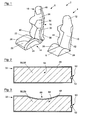
- Fig. 1 shows an exploded view of an embodiment of the motor vehicle seat according to the invention 2.
- the motor vehicle seat 2 is composed of a seat-shaped support structure 4 and a mat 6 together.
- the seat-shaped support structure 4 is rigid and cup-shaped and can be made for example of plastic.
- the support structure 4 includes a lower support portion 8, an upstanding back support portion 10 thereafter, and a head support portion 12 which adjoins the back support portion 10 upwardly.
- the mat 6 can be placed on the support structure 4, so that it is supported on the support structure 4 in the assembled motor vehicle seat 2 and preferably attached thereto.
- the mat 4 is composed of a seat part section 14, a backrest section 16 and a head restraint section 18.
- the seat portion 14 is supported on the lower support portion 8, the backrest portion 16 on the back support portion 10 and the headrest portion 18 on the head support portion 12 of the support structure 4.
- the mat 6 is composed of a plurality of cushions, which are connected to each other at the edges, that the mat 6 already forms a seat shape that corresponds approximately to the predetermined by the support structure 4 seat shape.
- the seat portion section 14 comprises two cushions 20, 22 which form the seat lying one behind the other, and two further cushions 24, 26 which are laterally connected to the first two cushions 20, 22 so that the cushions 24, 26 are upwards and prevent lateral slippage of the vehicle occupant.
- the latter is further supported by lateral, raised support members 28, 30 on the lower support portion 8 of the support structure 4.
- the backrest portion 16 comprises, on the one hand, three cushions 32, 34, 36 arranged one behind the other, which are the ones Form surface on which the vehicle occupant can support his back, and on the other two side cushions 38, 40 which are laterally connected to the cushions 32, 34, that the cushions 38, 40 are forward and also a lateral slippage of the vehicle occupant prevent. This is in turn assisted by two lateral, raised support members 42, 44 on the back support portion 10 of the support structure 4. In addition, the lateral ends of the cushion 36 are also inclined forwardly to securely support the vehicle occupant.
- the headrest portion 18 includes a pad 46 which connects upwardly with the pad 36 of the backrest portion 16 and is connected thereto.
- the basic structure of the cushion 32 of the backrest portion 16 is representative of all the aforementioned cushions 20, 22, 24, 34, 36, 38, 40 with reference to FIGS FIGS. 2 and 3 described, which have the same structure.
- the pad 32 has an airtight sheath 48 which is preferably made of an elastic material.
- a closable opening 50 is provided in the airtight sheath 48.
- a controllable valve 52 is provided in the opening 50. If it is a manually controllable valve 52, it should be arranged in the gripping area of the vehicle occupant, so that a quick and easy access is ensured.
- the airtight envelope 48 encloses a chamber 54. In the chamber 54, on the one hand air is enclosed and on the other hand a compressible foam filling 56 is arranged.
- the foam filling 56 is integrally formed as a continuous foam body 58.
- the foam filling 56 is adhesively bonded from the inside to the airtight sheath 48.
- the foam body 58 has an initial shape, in the Fig. 2 is shown. In the initial form, the foam body 58 has assumed its maximum volume. The foam body 58 is further formed so that it always returns to this initial shape when the foam body 58 and the pad 32 is not loaded and the airtight sheath 48 is vented through the opening 50 or is inflated, as will be explained in more detail below.
- the pad 32 can not be increased or decreased since the air present in the chamber 54 prevents compression or enlargement of the pad 32. If the valve 52 is opened and the pad is vented thereby, the weight of the vehicle occupant causes the air to escape from the chamber 54 through the opening 50 and the foam body 58 is compressed, as shown in FIG Fig. 3 is shown.
- a depression 60 has formed in the side of the cushion 32 facing the vehicle occupant, which has a negative shape of the ajar body part of the vehicle occupant. Now, a further reduction of the foam body 58 can be excluded by the valve 52 is closed again. The adapted to the vehicle occupant shape of the foam body 58 is retained, since the air within the chamber 54 prevents both a further change in volume of the pad 32.
- the procedure is as described below.
- the foam body 58 is compressed, but has a dimensional stability, which causes the foam body 58 again the in Fig. 2 shown returns when the pad 32 is unloaded and ventilated.
- foam body 58 forces itself back into its original shape and causes the volume of pad 32 to increase in volume compressed foam body 58 stored Energy. It only needs the pillow 32 to be ventilated.
- the air-tight sheath 48 of the pad 32 can still be additionally or exclusively evacuated and / or inflated by a pump (not shown), for which purpose a corresponding air line (not shown) can be provided which leads to the valve 52.
- a pump not shown
- a corresponding air line not shown
- the pad 32 could be increased or decreased by inflating or evacuating the airtight envelope 48, the foam body 58 being compressed by the contracting envelope 48 during evacuation.
- the adapted cushion shape is maintained by closing the valve 52.
- each of the cushions 20, 22, 24, 26, 32, 34, 36, 38, 40, 46 has the construction described above with a corresponding opening 50.
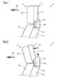
- FIGS 4 and 5 a modified embodiment described, with only the differences from the embodiment of the Fig. 1 to 3 is received and the above description otherwise applies accordingly.
- the same reference numerals are used for the same or similar parts.
- the back support portion 10 of the support structure 4 and the head support portion 12 of the support structure 4 are not rigidly connected to each other. Rather, starting from the head support portion 12, at least one rigid strut 62 extends to the back support portion 10, the strut 62 being fixedly connected to the head support portion 12 and movably connected to the back support portion 10.
- the strut may be 62 ⁇ m an axis 64 are pivoted, which extends transversely to the seating direction 66. The entire headrest, consisting of the headrest portion 12 and the pad 46 supported thereon, can thus be pivoted about the axis 64, so that the inclination of the headrest can be adjusted according to the wishes of the vehicle occupant.
- a pad 68 having the same construction as the above-described pads 20, 22, 24, 26, 32, 34, 36, 38, 40, 46 is provided to extend between the head support portion 12 and the back support portion 10 and on both sides supported.
- the head support portion 12 can be pivoted.
- the cushion 68 and its foam body 58 is compressed.
- the pad 68 expands and acts on the head support portion 12 to move about the axis 64 to the forward position (FIG. Fig. 5 ) is pivoted, as indicated by the arrow 70.
- the pad 68 In the reverse direction, the pad 68 would have to be vented again and relieved or evacuated. Should be evacuated when returning only with a pump without a corresponding restoring force is exerted on the head support portion 12, it is necessary that the cushion 68 and its sheath 48 is firmly connected to the head support portion 12 and the back support portion 10.
- the cushion 68 may be fixedly connected to the mat 6.
Abstract
Description
Die vorliegende Erfindung betrifft einen Kraftfahrzeugsitz mit mindestens einem belüftbaren und/oder aufblasbaren und/oder evakuierbaren Kissen, wobei das Kissen eine luftdichte Hülle aufweist, die eine Kammer umschließt, in der eine Füllung angeordnet ist.The present invention relates to a motor vehicle seat having at least one ventilatable and / or inflatable and / or evacuable cushion, the cushion having an airtight envelope enclosing a chamber in which a filling is arranged.
Aus dem Stand der Technik sind unterschiedliche Kraftfahrzeugsitze bekannt, die mit Kissen versehen sind, wobei die Kissen eine aufblasbare oder evakuierbare Hülle aufweisen. Die Kissen, die dem Komfort oder der Sicherheit des Fahrzeuginsassen dienen, sind dabei beispielsweise an dem Sitzteil, der Rückenlehne oder der Kopfstütze des Kraftfahrzeugsitzes angeordnet.Different motor vehicle seats are known from the prior art, which are provided with cushions, wherein the cushions have an inflatable or evakuierbare envelope. The cushions, which serve the comfort or safety of the vehicle occupant, are arranged, for example, on the seat part, the backrest or the headrest of the motor vehicle seat.
Aus der
Ein weiterer Kraftfahrzeugsitz mit mehreren Kissen ist aus der
Die
Anders ist dies bei dem Kraftfahrzeugsitz nach der
Es ist daher eine Aufgabe der vorliegenden Erfindung, einen Kraftfahrzeugsitz mit mindestens einem belüftbaren und/oder aufblasbaren und/oder evakuierbaren Kissen zu schaffen, bei dem das Kissen eine Füllung aufweist, wobei die Anpassung des Kissens auf den jeweiligen Fahrzeuginsassen vereinfacht und der Sitzkomfort erhöht sein soll.It is therefore an object of the present invention to provide a motor vehicle seat with at least one ventilatable and / or inflatable and / or evacuable cushion, in which the cushion has a filling, wherein the adaptation of the cushion to the respective vehicle occupants simplified and the seating comfort be increased should.
Diese Aufgabe wird durch die in Patentanspruch 1 angegebenen Merkmale gelöst. Vorteilhafte Ausführungsformen der Erfindung sind Gegenstand der Unteransprüche.This object is achieved by the features specified in claim 1. Advantageous embodiments of the invention are the subject of the dependent claims.
Der erfindungsgemäße Kraftfahrzeugsitz weist mindestens ein belüftbares und/oder aufblasbares und/oder evakuierbares Kissen auf. Das Kissen umfasst eine luftdichte Hülle, die entsprechend belüftbar, aufblasbar und/oder evakuierbar ist. Unter belüftbar ist hierbei zu verstehen, dass die Möglichkeit besteht, Luft in das Kissen ein- oder ausströmen zu lassen, beispielsweise mittels eines Ventils. Die luftdichte Hülle umschließt eine Kammer, in der - zusätzlich zu der vorhandenen Luftfüllung - eine weitere Füllung angeordnet ist. Erfindungsgemäß ist diese weitere Füllung als eine zusammendrückbare Schaumstofffüllung ausgebildet.The motor vehicle seat according to the invention has at least one ventilatable and / or inflatable and / or evacuatable cushion. The cushion comprises an air-tight envelope which can be ventilated, inflated and / or evacuated accordingly. Under ventilatable here is to be understood that there is the possibility of air in the pillow to flow in or out, for example by means of a valve. The airtight shell encloses a chamber in which - in addition to the existing air filling - another filling is arranged. According to the invention, this further filling is designed as a compressible foam filling.
Im Gegensatz zu dem aus der
Um die Fertigung des Kissens zu vereinfachen und eine weitgehend gleich bleibende Ausgangsform des Kissens zu gewährleisten, ist die Schaumstofffüllung in einer bevorzugten Ausführungsform des erfindungsgemäßen Kraftfahrzeugsitzes einstückig als ein zusammenhängender Schaumstoffkörper ausgebildet.In order to simplify the production of the pad and to ensure a substantially constant initial shape of the pad, the foam filling is integrally formed in a preferred embodiment of the motor vehicle seat according to the invention as a coherent foam body.
In einer weiteren bevorzugten Ausführungsform des erfindungsgemäßen Kraftfahrzeugsitzes ist das Kissen derart ausgebildet ist, dass es durch Belüften vergrößert werden kann. Die Vergrößerung des Volumens erfolgt demzufolge selbsttätig, sobald das Kissen belüftet wird. Es muss keine weitere Energie hinzugefügt werden, vielmehr ist die in der zusammengedrückten Schaumstofffüllung gespeicherte Energie ausreichend. Durch die Belüftung kann Luft in die Kammer des Kissens einströmen, so dass kein Unterdruck entsteht, der eine Vergrößerung verhindern könnte.In a further preferred embodiment of the motor vehicle seat according to the invention, the cushion is designed such that it can be increased by venting. The increase in volume is therefore automatically as soon as the pillow is vented. No additional energy needs to be added, but the energy stored in the compressed foam filling is sufficient. Through the ventilation air can flow into the chamber of the pad, so that no negative pressure is created, which could prevent an increase.
In einer weiteren bevorzugten Ausführungsform des erfindungsgemäßen Kraftfahrzeugsitzes ist das Kissen derart ausgebildet, dass es durch Belüften und Zusammendrücken unter Komprimierung der Schaumstofffüllung verkleinert werden kann. So müsste das belüftete Kissen lediglich durch das Gewicht des Fahrzeuginsassen belastet werden, um die Schaumstofffüllung und damit das Kissen zusammenzudrücken. Durch die Belüftung kann die innerhalb der Kammer vorhandene Luft entweichen und wirkt der Verkleinerung bzw. Anpassung nicht entgegen.In a further preferred embodiment of the motor vehicle seat according to the invention, the cushion is designed such that it by venting and compression under Compression of the foam filling can be reduced. Thus, the ventilated cushion would have to be loaded only by the weight of the vehicle occupant to compress the foam filling and thus the pillow. Through the ventilation, the air present within the chamber can escape and does not counteract the reduction or adaptation.
In einer vorteilhaften Ausführungsform des erfindungsgemäßen Kraftfahrzeugsitzes ist eine Pumpe zum Aufblasen und/oder Evakuieren der luftdichten Hülle vorgesehen. Dank der Pumpe kann die Anpassung des Kissens bzw. des Kraftfahrzeugsitzes an den jeweiligen Fahrzeuginsassen beschleunigt werden.In an advantageous embodiment of the motor vehicle seat according to the invention, a pump is provided for inflating and / or evacuating the airtight envelope. Thanks to the pump, the adaptation of the cushion or of the motor vehicle seat to the respective vehicle occupants can be accelerated.
Gemäß einer weiteren vorteilhaften Ausführungsform des erfindungsgemäßen Kraftfahrzeugsitzes kann das Kissen durch Aufpumpen der luftdichten Hülle vergrößert und/oder durch Evakuieren der luftdichten Hülle unter Komprimierung der Schaumstofffüllung verkleinert werden. So bewirkt ein Aufpumpen eine Vergrößerung der Kammer, an die sich die Schaumstofffüllung entsprechend anpassen kann, wohingegen ein Evakuieren eine Verkleinerung der Kammer bewirkt, so dass die Schaumstofffüllung durch die sich zusammenziehende Hülle zusammengedrückt wird.According to a further advantageous embodiment of the motor vehicle seat according to the invention, the cushion can be increased by inflating the airtight envelope and / or reduced by evacuating the airtight envelope while compressing the foam filling. Thus, inflating causes an enlargement of the chamber to which the foam filling can adapt accordingly, whereas evacuation causes a reduction of the chamber, so that the foam filling is compressed by the contracting shell.
In einer besonders bevorzugten Ausführungsform des erfindungsgemäßen Kraftfahrzeugsitzes weist der Schaumstoffkörper eine Ausgangsform auf, in der der Schaumstoffkörper sein maximales Volumen hat, wobei der Schaumstoffkörper derart ausgebildet ist, dass der Schaumstoffkörper im unbelasteten Zustand bei belüftetem Kissen stets in die Ausgangsform zurückkehrt. Diese elastische Verformung des Schaumstoffkörpers bewirkt somit ein selbsttätiges Zurückstellen des Kissens in seine Ausgangsform, wenn das unbelastete Kissen belüftet oder aufgepumpt wird.In a particularly preferred embodiment of the motor vehicle seat according to the invention, the foam body has an initial shape in which the foam body has its maximum volume, wherein the foam body is formed such that the foam body always returns in the unloaded state with ventilated cushion in the initial shape. This elastic deformation of the foam body thus causes an automatic return of the pad to its original shape when the unloaded pad is vented or inflated.
In einer weiteren vorteilhaften Ausführungsform des erfindungsgemäßen Kraftfahrzeugsitzes ist mindestens eine verschließbare Öffnung zum Belüften und/oder Aufblasen und/oder Evakuieren des Kissens in der luftdichten Hülle vorgesehen. In der Öffnung kann beispielsweise ein steuerbares Ventil angeordnet sein.In a further advantageous embodiment of the motor vehicle seat according to the invention is at least one closable opening for venting and / or inflation and / or evacuation of the cushion provided in the airtight envelope. For example, a controllable valve can be arranged in the opening.
Gemäß einer weiteren bevorzugten Ausführungsform des erfindungsgemäßen Kraftfahrzeugsitzes ist eine Volumenänderung des Kissens bei geschlossener Öffnung unterbunden. So würde der Verkleinerung ein Überdruck und der Vergrößerung ein Unterdruck innerhalb des Kissens bzw. der luftdichten Hülle entgegenwirken.According to a further preferred embodiment of the motor vehicle seat according to the invention, a change in volume of the cushion is prevented when the opening is closed. Thus, the reduction would counteract an overpressure and the increase in negative pressure within the pad or the airtight envelope.
In einer weiteren vorteilhaften Ausführungsform des erfindungsgemäßen Kraftfahrzeugsitzes ist ein steuerbares Ventil, vorzugsweise ein manuell steuerbares Ventil, zum Öffnen und Schließen der Öffnung vorgesehen. Ein manuell steuerbares Ventil könnte beispielsweise im Griffbereich des Fahrzeuginsassen vorgesehen sein.In a further advantageous embodiment of the motor vehicle seat according to the invention, a controllable valve, preferably a manually controllable valve, is provided for opening and closing the opening. A manually controllable valve could be provided, for example, in the grip area of the vehicle occupant.
In einer weiteren vorteilhaften Ausführungsform des erfindungsgemäßen Kraftfahrzeugsitzes umfasst der Kraftfahrzeugsitz mehrere Kissen mit dem zuvor beschriebenen Aufbau.In a further advantageous embodiment of the motor vehicle seat according to the invention, the motor vehicle seat comprises a plurality of cushions with the construction described above.
Um bei der Montage des Kraftfahrzeugsitzes eine genaue Positionierung der Kissen zueinander zu erreichen und gleichzeitig die Montage zu vereinfachen, sind die Kissen in einer weiteren bevorzugten Ausführungsform des erfindungsgemäßen Kraftfahrzeugsitzes unter Ausbildung einer auflegbaren Matte miteinander verbunden. Hierunter kann auch eine Matte verstanden werden, die bereits sitzförmig ausgebildet ist.In order to achieve an exact positioning of the cushions to each other during assembly of the motor vehicle seat and at the same time to simplify the assembly, the cushions are connected to each other in a further preferred embodiment of the motor vehicle seat according to the invention to form a auflegbaren mat. This may also be understood as meaning a mat which is already seated.
Grundsätzlich können die mehreren Kissen gemeinsam belüftet, evakuiert oder aufgeblasen werden, indem zwischen deren Kammern eine Strömungsverbindung besteht. Um jedoch eine besonders individuelle Anpassung des Kraftfahrzeugsitzes an den jeweiligen Fahrzeuginsassen zu ermöglichen können die Kissen der Matte in einer weiteren bevorzugten Ausführungsform des erfindungsgemäßen Kraftfahrzeugsitzes unabhängig voneinander belüftet, aufgeblasen und/oder evakuiert werden.In principle, the plurality of cushions can be vented, evacuated or inflated together by having a flow connection between their chambers. However, in order to allow a particularly individual adaptation of the vehicle seat to the respective vehicle occupants, the cushions of Mat in a further preferred embodiment of the motor vehicle seat according to the invention are independently ventilated, inflated and / or evacuated.
Gemäß einer weiteren vorteilhaften Ausführungsform des erfindungsgemäßen Kraftfahrzeugsitzes weist der Kraftfahrzeugsitz eine sitzförmige, starre Stützstruktur auf, an der die Kissen oder die Matte abgestützt und/oder befestigt sind.According to a further advantageous embodiment of the motor vehicle seat according to the invention, the motor vehicle seat has a seat-shaped, rigid support structure on which the cushions or the mat are supported and / or fastened.
In einer weiteren vorteilhaften Ausführungsform des erfindungsgemäßen Kraftfahrzeugsitzes weist die Stützstruktur einen Rückenstützabschnitt und einen beweglich an dem Rückenstützabschnitt angeordneten Kopfstützabschnitt auf. Die Anpassung der Kopfabstützung kann somit beispielsweise sowohl anhand eines Kissens, das vor dem Kopfstützabschnitt angeordnet ist, als auch mit Hilfe des Kopfstützabschnittes selbst erfolgen. Der Kopfstützabschnitt der Stützstruktur kann beispielsweise in der Höhe oder der Neigung verstellt werden.In a further advantageous embodiment of the motor vehicle seat according to the invention, the support structure has a back support section and a head support section movably arranged on the back support section. The adjustment of the head support can thus be done, for example, both by means of a pad, which is arranged in front of the head support portion, as well as with the help of the head support portion itself. The headrest portion of the support structure can be adjusted in height or inclination, for example.
In einer weiteren bevorzugten Ausführungsform des erfindungsgemäßen Kraftfahrzeugsitzes ist der Kopfstützabschnitt der Stützstruktur verschwenkbar an dem Rückenstützabschnitt der Stützstruktur angeordnet. Vorzugsweise kann der Kopfstützabschnitt um eine Achse quer zur Sitzrichtung verschenkt werden. Auf diese Weise kann die Neigung der gesamten Kopfstütze, die mindestens ein Kissen und den Kopfstützabschnitt der Stützstruktur umfasst, verändert werden.In a further preferred embodiment of the motor vehicle seat according to the invention, the head support portion of the support structure is pivotably arranged on the back support portion of the support structure. Preferably, the head support portion may be given away about an axis transverse to the seat direction. In this way, the inclination of the entire headrest comprising at least one pad and the head support portion of the support structure can be changed.
Um für die Verstellung des Kopfstützabschnittes der Stützstruktur nicht auf einen zusätzlichen Antrieb zurückgreifen zu müssen, ist in einer weiteren besonders bevorzugten Ausführungsform des erfindungsgemäßen Kraftfahrzeugsitzes mindestens ein Kissen derart an der Stützstruktur angeordnet, dass der Kopfstützabschnitt durch Volumenänderung des Kissens bewegbar oder verschwenkbar ist. So kann dieses Kissen beispielsweise einerseits an dem Kopfstützabschnitt und andererseits an dem Rückenlehnenabschnitt abgestützt sein, um bei einer Volumenänderung ein relatives Verstellen des Kopfstützabschnitts gegenüber dem Rückenlehnenabschnitt zu bewirken.In order not to have to resort to an additional drive for the adjustment of the head support portion of the support structure, at least one cushion is arranged on the support structure in a further particularly preferred embodiment of the motor vehicle seat according to the invention that the head support portion is movable or pivotable by volume change of the pad. For example, this cushion may be supported, on the one hand, on the headrest section and, on the other hand, on the backrest section, in order to to cause a relative displacement of the headrest portion relative to the backrest portion at a volume change.
Damit die luftdichte Hülle einer Formänderung der Schaumstofffüllung sicher folgt, ist die Schaumstofffüllung in einer weiteren bevorzugten Ausführungsform des erfindungsgemäßen Kraftfahrzeugsitzes mit der luftdichten Hülle flächig verbunden, vorzugsweise verklebt.In order for the airtight envelope to reliably follow a change in shape of the foam filling, the foam filling in a further preferred embodiment of the motor vehicle seat according to the invention is connected in a planar manner to the airtight envelope, preferably adhesively bonded.
Die Erfindung wird im Folgenden anhand von beispielhaften Ausführungsformen unter Bezugnahme auf die beigefügten Zeichnungen näher erläutert. Es zeigen:
- Fig. 1
- eine perspektivische Explosionsdarstellung des erfindungsgemäßen Kraftfahrzeugsitzes in einer ersten Ausführungsform,
- Fig. 2
- eine geschnittene Darstellung eines einzelnen Kissens des Kraftfahrzeugsitzes von
Fig. 1 mit der Schaumstofffüllung in der Ausgangsform, - Fig. 3
- das Kissen von
Fig. 3 mit der Schaumstofffüllung in einer teilweise zusammengedrückten Form, - Fig. 4
- eine teilweise Seitenansicht des Kraftfahrzeugsitzes von
Fig. 1 in einer alternativen Ausführungsform mit dem Kopfstützabschnitt in einer hinteren Stellung und - Fig. 5
- den Kraftfahrzeugsitz von
Fig. 4 mit dem Kopfstützabschnitt in einer vorderen Stellung.
- Fig. 1
- an exploded perspective view of the motor vehicle seat according to the invention in a first embodiment,
- Fig. 2
- a sectional view of a single pad of the motor vehicle seat of
Fig. 1 with the foam filling in the original form, - Fig. 3
- the pillow of
Fig. 3 with the foam filling in a partially compressed form, - Fig. 4
- a partial side view of the vehicle seat of
Fig. 1 in an alternative embodiment with the headrest portion in a rearward position and - Fig. 5
- the motor vehicle seat of
Fig. 4 with the headrest portion in a front position.
Die Matte 4 setzt sich aus einem Sitzteilabschnitt 14, einem Rückenlehnenabschnitt 16 und einem Kopfstützenabschnitt 18 zusammen. Im zusammengebauten Zustand des Kraftfahrzeugsitzes 2 ist der Sitzteilabschnitt 14 an dem unteren Stützabschnitt 8, der Rückenlehnenabschnitt 16 an dem Rückenstützabschnitt 10 und der Kopfstützenabschnitt 18 an dem Kopfstützabschnitt 12 der Stützstruktur 4 abgestützt. Insgesamt setzt sich die Matte 6 aus mehreren Kissen zusammen, die derart randseitig miteinander verbunden sind, dass auch die Matte 6 bereits eine Sitzform ausbildet, die in etwa der durch die Stützstruktur 4 vorgegebenen Sitzform entspricht.The
So umfasst der Sitzteilabschnitt 14 zwei Kissen 20, 22, die hintereinander liegend die Sitzfläche ausbilden, sowie zwei weitere Kissen 24, 26, die derart seitlich mit den beiden erstgenannten Kissen 20, 22 verbunden sind, dass die Kissen 24, 26 nach oben stehen und ein seitliches Verrutschen des Fahrzeuginsassen verhindern. Letzteres wird ferner durch seitliche, erhabene Stützteile 28, 30 an dem unteren Stützabschnitt 8 der Stützstruktur 4 unterstützt.Thus, the
Der Rückenlehnenabschnitt 16 umfasst zum einen drei hintereinander angeordnete Kissen 32, 34, 36, die diejenige Fläche ausbilden, an der der Fahrzeuginsasse seinen Rücken abstützen kann, und zum anderen zwei seitliche Kissen 38, 40, die derart seitlich mit den Kissen 32, 34 verbunden sind, dass die Kissen 38, 40 nach vorne stehen und ebenfalls ein seitliches Verrutschen des Fahrzeuginsassen verhindern. Dies wird wiederum unterstützt von zwei seitlichen, erhabenen Stützteile 42, 44 an dem Rückenstützabschnitt 10 der Stützstruktur 4. Darüber hinaus sind die seitlichen Enden des Kissens 36 ebenfalls nach vorne geneigt, um den Fahrzeuginsassen sicher zu stützen.The
Der Kopfstützenabschnitt 18 umfasst ein Kissen 46, das sich nach oben an das Kissen 36 des Rückenlehnenabschnitts 16 anschließt und mit diesem verbunden ist.The
Nachstehend wird der grundsätzliche Aufbau des Kissens 32 des Rückenlehnenabschnitts 16 stellvertretend für alle vorstehend genannten Kissen 20, 22, 24, 34, 36, 38, 40 unter Bezugnahme auf die
Das Kissen 32 weist eine luftdichte Hülle 48 auf, die vorzugsweise aus einem elastischen Material besteht. In der luftdichten Hülle 48 ist eine verschließbare Öffnung 50 vorgesehen. Um die Öffnung 50 verschließen und auch wieder öffnen zu können, ist ein steuerbares Ventil 52 in der Öffnung 50 vorgesehen. Sofern es sich um ein manuell steuerbares Ventil 52 handelt, sollte es im Greifbereich des Fahrzeuginsassen angeordnet sein, so dass ein schneller und einfacher Zugriff gewährleistet ist. Die luftdichte Hülle 48 umschließt eine Kammer 54. In der Kammer 54 ist zum einen Luft eingeschlossen und zum anderen eine zusammendrückbare Schaumstofffüllung 56 angeordnet. Die Schaumstofffüllung 56 ist einstückig als ein zusammenhängender Schaumstoffkörper 58 ausgebildet. Die Schaumstofffüllung 56 ist von innen flächig mit der luftdichten Hülle 48 verklebt.The
Der Schaumstoffkörper 58 weist eine Ausgangsform auf, die in
Solange das Ventil 52 geschlossen ist, kann das Kissen 32 nicht vergrößert oder verkleinert werden, da die in der Kammer 54 vorhandene Luft ein Zusammendrücken oder Vergrößern des Kissens 32 verhindert. Wird das Ventil 52 geöffnet und das Kissen dadurch belüftet, so bewirkt das Gewicht des Fahrzeuginsassen, dass die Luft aus der Kammer 54 durch die Öffnung 50 entweicht und der Schaumstoffkörper 58 zusammengedrückt wird, wie dies in
Um das Kissen 32 in der Folgezeit wieder an einen neuen Fahrzeuginsassen anpassen zu können, wird wie nachstehend beschrieben vorgegangen. Der Schaumstoffkörper 58 ist zusammengedrückt, weist jedoch eine Formstabilität auf, die dazu führt, dass der Schaumstoffkörper 58 wieder die in
Die luftdichte Hülle 48 des Kissens 32 kann dennoch zusätzlich oder auch ausschließlich von einer Pumpe (nicht dargestellt) evakuiert und/oder aufgeblasen werden, wobei zu diesem Zweck eine entsprechende Luftleitung (nicht dargestellt) vorgesehen werden kann, die zu dem Ventil 52 führt. So könnte das Kissen 32 bei dieser alternativen Ausführungsform durch Aufpumpen bzw. Evakuieren der luftdichten Hülle 48 vergrößert bzw. verkleinert werden, wobei der Schaumstoffkörper 58 beim Evakuieren durch die sich zusammenziehende Hülle 48 komprimiert würde. Auch bei dieser Ausführungsvariante bleibt die angepasste Kissenform durch Schließen des Ventils 52 erhalten.The air-
Um eine besonders individuelle Anpassung des Kraftfahrzeugsitzes 2 an den jeweiligen Fahrzeuginsassen zu ermöglichen, können die Kissen 20, 22, 24, 26, 32, 34, 36, 38, 40, 46 der Matte 6 unabhängig voneinander belüftet, aufgeblasen und/oder evakuiert werden. Zu diesem Zweck weist jedes der Kissen 20, 22, 24, 26, 32, 34, 36, 38, 40, 46 den zuvor beschriebenen Aufbau mit einer entsprechenden Öffnung 50 auf.In order to allow a particularly individual adaptation of the
Nachstehend wird unter Bezugnahme auf die
Bei der abgewandelten Ausführungsform sind der Rückenstützabschnitt 10 der Stützstruktur 4 und der Kopfstützabschnitt 12 der Stützstruktur 4 nicht starr miteinander verbunden. Vielmehr erstreckt sich ausgehend von dem Kopfstützabschnitt 12 mindestens eine starre Strebe 62 bis zu dem Rückenstützabschnitt 10, wobei die Strebe 62 fest mit dem Kopfstützabschnitt 12 und beweglich mit dem Rückenstützabschnitt 10 verbunden ist. Im vorliegenden Beispiel kann die Strebe 62 um eine Achse 64 verschwenkt werden, die sich quer zur Sitzrichtung 66 erstreckt. Die gesamte Kopfstütze, bestehend aus dem Kopfstützabschnitt 12 und dem daran abgestützten Kissen 46, kann somit um die Achse 64 verschwenkt werden, so dass die Neigung der Kopfstütze dem Wunsch des Fahrzeuginsassen entsprechend eingestellt werden kann. Zu diesem Zweck ist jedoch kein zusätzlicher Antrieb vorgesehen. Vielmehr ist ein Kissen 68, das denselben Aufbau wie die vorbeschriebenen Kissen 20, 22, 24, 26, 32, 34, 36, 38, 40, 46 hat, vorgesehen, dass sich zwischen den Kopfstützabschnitt 12 und den Rückenstützabschnitt 10 erstreckt und sich beiderseits abstützt.In the modified embodiment, the
Aufgrund der bereits zuvor erläuterten Volumenänderung des Kissens 68 durch Belüften, Aufpumpen und/oder Evakuieren, kann der Kopfstützabschnitt 12 verschwenkt werden. In der hinteren Stellung des Kopfstützabschnitts 12 (
In umgekehrter Richtung müsste das Kissen 68 wieder belüftet und entlastet oder evakuiert werden. Sollte beim Zurückstellen lediglich mit einer Pumpe evakuiert werden, ohne dass eine entsprechende Rückstellkraft auf den Kopfstützabschnitt 12 ausgeübt wird, ist es erforderlich, dass das Kissen 68 bzw. dessen Hülle 48 fest mit dem Kopfstützabschnitt 12 und dem Rückenstützabschnitt 10 verbunden ist. Das Kissen 68 kann fest mit der Matte 6 verbunden sein.In the reverse direction, the
- 22
- KraftfahrzeugsitzAutomotive seat
- 44
- Stützstruktursupport structure
- 66
- Mattemat
- 88th
- unterer Stützabschnitt der Stützstrukturlower support portion of the support structure
- 1010
- Rückenstützabschnitt der StützstrukturBack support portion of the support structure
- 1212
- Kopfstützabschnitt der StützstrukturHead support portion of the support structure
- 1414
- Sitzteilabschnitt der MatteSeat section of the mat
- 1616
- Rückenlehnenabschnitt der MatteBackrest section of the mat
- 1818
- Kopfstützenabschnitt der MatteHeadrest section of the mat
- 2020
- Kissenpillow
- 2222
- Kissenpillow
- 2424
- Kissenpillow
- 2626
- Kissenpillow
- 2828
- Stützteilsupporting part
- 3030
- Stützteilsupporting part
- 3232
- Kissenpillow
- 3434
- Kissenpillow
- 3636
- Kissenpillow
- 3838
- Kissenpillow
- 4040
- Kissenpillow
- 4242
- Stützteilsupporting part
- 4444
- Stützteilsupporting part
- 4646
- Kissenpillow
- 4848
- luftdichte Hülleairtight shell
- 5050
- Öffnungopening
- 5252
- VentilValve
- 5454
- Kammerchamber
- 5656
- Schaumstofffüllungfoam filling
- 5858
- zusammenhängender Schaumstoffkörpercoherent foam body
- 6060
- Muldetrough
- 6262
- Strebestrut
- 6464
- Achseaxis
- 6666
- Sitzrichtungseat direction
- 6868
- Kissenpillow
- 7070
- Pfeilarrow
Claims (18)
Applications Claiming Priority (1)
| Application Number | Priority Date | Filing Date | Title |
|---|---|---|---|
| DE102007026382A DE102007026382A1 (en) | 2007-06-06 | 2007-06-06 | Motor vehicle seat with a ventilated cushion with foam filling |
Publications (3)
| Publication Number | Publication Date |
|---|---|
| EP2006151A2 true EP2006151A2 (en) | 2008-12-24 |
| EP2006151A3 EP2006151A3 (en) | 2009-08-19 |
| EP2006151B1 EP2006151B1 (en) | 2014-02-26 |
Family
ID=39942108
Family Applications (1)
| Application Number | Title | Priority Date | Filing Date |
|---|---|---|---|
| EP08004538.8A Not-in-force EP2006151B1 (en) | 2007-06-06 | 2008-03-12 | Motor vehicle seat with an inflatable cushion having a foam padding |
Country Status (2)
| Country | Link |
|---|---|
| EP (1) | EP2006151B1 (en) |
| DE (1) | DE102007026382A1 (en) |
Cited By (1)
| Publication number | Priority date | Publication date | Assignee | Title |
|---|---|---|---|---|
| US9468301B2 (en) | 2013-04-30 | 2016-10-18 | Tropitone Furniture Co., Inc. | Seating with adjustable cushions |
Families Citing this family (3)
| Publication number | Priority date | Publication date | Assignee | Title |
|---|---|---|---|---|
| DE102009012616A1 (en) | 2009-03-11 | 2010-09-16 | GM Global Technology Operations, Inc., Detroit | Air cushion for vehicle seat, has air-tight, elastically deformable casing, which is aeratable, inflatable or evacuatable, where elastically deformable foam body is arranged within casing |
| US10576862B1 (en) | 2018-10-01 | 2020-03-03 | GM Global Technology Operations LLC | Head restraint for vehicle passenger seat |
| DE102020103734A1 (en) | 2020-02-13 | 2021-08-19 | Bayerische Motoren Werke Aktiengesellschaft | Seating element for a vehicle and vehicle |
Citations (4)
| Publication number | Priority date | Publication date | Assignee | Title |
|---|---|---|---|---|
| DE19910427A1 (en) | 1999-03-10 | 2000-09-21 | Daimler Chrysler Ag | Passenger seat |
| WO2001013767A1 (en) | 1999-08-20 | 2001-03-01 | Mccord Winn Textron Inc. | Vehicle impact responsive multiple bladder seating and headrest system and method |
| DE29924138U1 (en) | 1998-05-12 | 2002-09-19 | Ctex Seat Comfort Ltd | seat assembly |
| DE19806535C2 (en) | 1997-02-19 | 2002-09-26 | Gen Motors Corp | Device and method for automatically adjusting the comfort of a motor vehicle seat |
Family Cites Families (3)
| Publication number | Priority date | Publication date | Assignee | Title |
|---|---|---|---|---|
| WO1997045038A1 (en) * | 1996-05-28 | 1997-12-04 | Deka Products Limited Partnership | Constant pressure seating system |
| US5772281A (en) * | 1997-05-19 | 1998-06-30 | Lear Corporation | Dual spring back suspension system for an automotive seat |
| CA2285813A1 (en) * | 1998-12-07 | 2000-06-07 | Basf Corporation | Polyurethane foam seating components |
-
2007
- 2007-06-06 DE DE102007026382A patent/DE102007026382A1/en not_active Withdrawn
-
2008
- 2008-03-12 EP EP08004538.8A patent/EP2006151B1/en not_active Not-in-force
Patent Citations (4)
| Publication number | Priority date | Publication date | Assignee | Title |
|---|---|---|---|---|
| DE19806535C2 (en) | 1997-02-19 | 2002-09-26 | Gen Motors Corp | Device and method for automatically adjusting the comfort of a motor vehicle seat |
| DE29924138U1 (en) | 1998-05-12 | 2002-09-19 | Ctex Seat Comfort Ltd | seat assembly |
| DE19910427A1 (en) | 1999-03-10 | 2000-09-21 | Daimler Chrysler Ag | Passenger seat |
| WO2001013767A1 (en) | 1999-08-20 | 2001-03-01 | Mccord Winn Textron Inc. | Vehicle impact responsive multiple bladder seating and headrest system and method |
Cited By (1)
| Publication number | Priority date | Publication date | Assignee | Title |
|---|---|---|---|---|
| US9468301B2 (en) | 2013-04-30 | 2016-10-18 | Tropitone Furniture Co., Inc. | Seating with adjustable cushions |
Also Published As
| Publication number | Publication date |
|---|---|
| EP2006151B1 (en) | 2014-02-26 |
| EP2006151A3 (en) | 2009-08-19 |
| DE102007026382A1 (en) | 2008-12-11 |
Similar Documents
| Publication | Publication Date | Title |
|---|---|---|
| DE102006037521B4 (en) | System for the automatic adjustment of seats, in particular vehicle seats and seats for automobiles, aircraft or the like with such a system | |
| DE102017111429B4 (en) | Device for adjusting the contour of a seat, in particular a vehicle seat, and seat, in particular a vehicle seat, with such a device | |
| DE202017103162U1 (en) | Device for contour adjustment of a seat, in particular a vehicle seat, and seat, in particular vehicle seat with such a device | |
| EP2006152B1 (en) | Cushion for a motor vehicle, motor vehicle seat with such a cushion and method for manufacturing such a cushion | |
| DE102008024871A1 (en) | Motor vehicle seat, has valve arrangement releasing opening with common cross section in open position, so that blister is deaerated through opening, where common cross section is larger than another common cross section of another opening | |
| DE102007026380A1 (en) | Inner arrangement for a vehicle comprises inflatable cushions arranged on a base body for producing an armrest surface | |
| EP3142892B1 (en) | Vehicle seat with adjustable seating surface and method of adjusting a seating surface | |
| WO2008104368A1 (en) | Device and method for adjusting a side cheek of a seat | |
| DE19740588B4 (en) | Backrest of a vehicle seat that has an adjustable shoulder rest | |
| DE102008028353A1 (en) | vehicle seat | |
| EP2006151B1 (en) | Motor vehicle seat with an inflatable cushion having a foam padding | |
| EP2149475A1 (en) | Seat with reforming device for adjusting the seat contour | |
| DE102012009591A1 (en) | Vehicle seat for a motor vehicle | |
| WO2000053453A1 (en) | Passenger seat with pneumatically regulatable and reversibly deformable vacuum cushion | |
| DE3904090A1 (en) | Seat, in particular vehicle seat | |
| DE102009012693B4 (en) | Bucket seat for a motor vehicle | |
| DE102007032448A1 (en) | Motor vehicle seat, has side bolster hinged on another side bolster, where side bolsters respectively comprise venting and/or inflatable and/or evacuatable airtight bubbles, and compressible foam material content arranged in bubbles | |
| DE10036261A1 (en) | headrest | |
| DE102009012620A1 (en) | Vehicle seat with a contour-adjustable support surface | |
| DE102011116449A1 (en) | Seat for motor vehicle, has seat unit with seat surface, where seat unit is divided in transverse direction of vehicle seat in seat-unit elements, and air bellows is arranged between two seat-unit elements for moving seat-unit elements | |
| DE19961172A1 (en) | Vehicle seat with adjustable backrest, headrest and lumbar support, with lumbar support and headrest coupled so that adjustment of one also alters other | |
| EP1561635B1 (en) | Inflatable assembly | |
| DE112007003011T5 (en) | Vehicle seat with a completely simultaneous adjustment | |
| WO2020234140A1 (en) | Motor vehicle seat | |
| DE102007026379B4 (en) | Motor vehicle seat with a pillow |
Legal Events
| Date | Code | Title | Description |
|---|---|---|---|
| PUAI | Public reference made under article 153(3) epc to a published international application that has entered the european phase |
Free format text: ORIGINAL CODE: 0009012 |
|
| AK | Designated contracting states |
Kind code of ref document: A2 Designated state(s): AT BE BG CH CY CZ DE DK EE ES FI FR GB GR HR HU IE IS IT LI LT LU LV MC MT NL NO PL PT RO SE SI SK TR |
|
| AX | Request for extension of the european patent |
Extension state: AL BA MK RS |
|
| PUAL | Search report despatched |
Free format text: ORIGINAL CODE: 0009013 |
|
| AK | Designated contracting states |
Kind code of ref document: A3 Designated state(s): AT BE BG CH CY CZ DE DK EE ES FI FR GB GR HR HU IE IS IT LI LT LU LV MC MT NL NO PL PT RO SE SI SK TR |
|
| AX | Request for extension of the european patent |
Extension state: AL BA MK RS |
|
| 17P | Request for examination filed |
Effective date: 20100219 |
|
| AKX | Designation fees paid |
Designated state(s): AT BE BG CH CY CZ DE DK EE ES FI FR GB GR HR HU IE IS IT LI LT LU LV MC MT NL NO PL PT RO SE SI SK TR |
|
| 17Q | First examination report despatched |
Effective date: 20100318 |
|
| R17C | First examination report despatched (corrected) |
Effective date: 20110311 |
|
| RAP1 | Party data changed (applicant data changed or rights of an application transferred) |
Owner name: GM GLOBAL TECHNOLOGY OPERATIONS LLC |
|
| GRAP | Despatch of communication of intention to grant a patent |
Free format text: ORIGINAL CODE: EPIDOSNIGR1 |
|
| INTG | Intention to grant announced |
Effective date: 20130923 |
|
| GRAS | Grant fee paid |
Free format text: ORIGINAL CODE: EPIDOSNIGR3 |
|
| GRAA | (expected) grant |
Free format text: ORIGINAL CODE: 0009210 |
|
| AK | Designated contracting states |
Kind code of ref document: B1 Designated state(s): AT BE BG CH CY CZ DE DK EE ES FI FR GB GR HR HU IE IS IT LI LT LU LV MC MT NL NO PL PT RO SE SI SK TR |
|
| REG | Reference to a national code |
Ref country code: GB Ref legal event code: FG4D Free format text: NOT ENGLISH |
|
| REG | Reference to a national code |
Ref country code: CH Ref legal event code: EP |
|
| REG | Reference to a national code |
Ref country code: AT Ref legal event code: REF Ref document number: 653377 Country of ref document: AT Kind code of ref document: T Effective date: 20140315 |
|
| REG | Reference to a national code |
Ref country code: IE Ref legal event code: FG4D Free format text: LANGUAGE OF EP DOCUMENT: GERMAN |
|
| REG | Reference to a national code |
Ref country code: DE Ref legal event code: R096 Ref document number: 502008011332 Country of ref document: DE Effective date: 20140410 |
|
| REG | Reference to a national code |
Ref country code: NL Ref legal event code: VDEP Effective date: 20140226 |
|
| REG | Reference to a national code |
Ref country code: LT Ref legal event code: MG4D |
|
| PG25 | Lapsed in a contracting state [announced via postgrant information from national office to epo] |
Ref country code: NO Free format text: LAPSE BECAUSE OF FAILURE TO SUBMIT A TRANSLATION OF THE DESCRIPTION OR TO PAY THE FEE WITHIN THE PRESCRIBED TIME-LIMIT Effective date: 20140526 Ref country code: IS Free format text: LAPSE BECAUSE OF FAILURE TO SUBMIT A TRANSLATION OF THE DESCRIPTION OR TO PAY THE FEE WITHIN THE PRESCRIBED TIME-LIMIT Effective date: 20140626 Ref country code: LT Free format text: LAPSE BECAUSE OF FAILURE TO SUBMIT A TRANSLATION OF THE DESCRIPTION OR TO PAY THE FEE WITHIN THE PRESCRIBED TIME-LIMIT Effective date: 20140226 |
|
| PG25 | Lapsed in a contracting state [announced via postgrant information from national office to epo] |
Ref country code: SE Free format text: LAPSE BECAUSE OF FAILURE TO SUBMIT A TRANSLATION OF THE DESCRIPTION OR TO PAY THE FEE WITHIN THE PRESCRIBED TIME-LIMIT Effective date: 20140226 Ref country code: FI Free format text: LAPSE BECAUSE OF FAILURE TO SUBMIT A TRANSLATION OF THE DESCRIPTION OR TO PAY THE FEE WITHIN THE PRESCRIBED TIME-LIMIT Effective date: 20140226 Ref country code: CY Free format text: LAPSE BECAUSE OF FAILURE TO SUBMIT A TRANSLATION OF THE DESCRIPTION OR TO PAY THE FEE WITHIN THE PRESCRIBED TIME-LIMIT Effective date: 20140226 Ref country code: PT Free format text: LAPSE BECAUSE OF FAILURE TO SUBMIT A TRANSLATION OF THE DESCRIPTION OR TO PAY THE FEE WITHIN THE PRESCRIBED TIME-LIMIT Effective date: 20140626 Ref country code: NL Free format text: LAPSE BECAUSE OF FAILURE TO SUBMIT A TRANSLATION OF THE DESCRIPTION OR TO PAY THE FEE WITHIN THE PRESCRIBED TIME-LIMIT Effective date: 20140226 |
|
| PG25 | Lapsed in a contracting state [announced via postgrant information from national office to epo] |
Ref country code: LV Free format text: LAPSE BECAUSE OF FAILURE TO SUBMIT A TRANSLATION OF THE DESCRIPTION OR TO PAY THE FEE WITHIN THE PRESCRIBED TIME-LIMIT Effective date: 20140226 Ref country code: HR Free format text: LAPSE BECAUSE OF FAILURE TO SUBMIT A TRANSLATION OF THE DESCRIPTION OR TO PAY THE FEE WITHIN THE PRESCRIBED TIME-LIMIT Effective date: 20140226 |
|
| PG25 | Lapsed in a contracting state [announced via postgrant information from national office to epo] |
Ref country code: DK Free format text: LAPSE BECAUSE OF FAILURE TO SUBMIT A TRANSLATION OF THE DESCRIPTION OR TO PAY THE FEE WITHIN THE PRESCRIBED TIME-LIMIT Effective date: 20140226 Ref country code: RO Free format text: LAPSE BECAUSE OF FAILURE TO SUBMIT A TRANSLATION OF THE DESCRIPTION OR TO PAY THE FEE WITHIN THE PRESCRIBED TIME-LIMIT Effective date: 20140226 Ref country code: EE Free format text: LAPSE BECAUSE OF FAILURE TO SUBMIT A TRANSLATION OF THE DESCRIPTION OR TO PAY THE FEE WITHIN THE PRESCRIBED TIME-LIMIT Effective date: 20140226 Ref country code: CZ Free format text: LAPSE BECAUSE OF FAILURE TO SUBMIT A TRANSLATION OF THE DESCRIPTION OR TO PAY THE FEE WITHIN THE PRESCRIBED TIME-LIMIT Effective date: 20140226 |
|
| REG | Reference to a national code |
Ref country code: CH Ref legal event code: PL |
|
| REG | Reference to a national code |
Ref country code: DE Ref legal event code: R097 Ref document number: 502008011332 Country of ref document: DE |
|
| PG25 | Lapsed in a contracting state [announced via postgrant information from national office to epo] |
Ref country code: SK Free format text: LAPSE BECAUSE OF FAILURE TO SUBMIT A TRANSLATION OF THE DESCRIPTION OR TO PAY THE FEE WITHIN THE PRESCRIBED TIME-LIMIT Effective date: 20140226 Ref country code: ES Free format text: LAPSE BECAUSE OF FAILURE TO SUBMIT A TRANSLATION OF THE DESCRIPTION OR TO PAY THE FEE WITHIN THE PRESCRIBED TIME-LIMIT Effective date: 20140226 Ref country code: MC Free format text: LAPSE BECAUSE OF FAILURE TO SUBMIT A TRANSLATION OF THE DESCRIPTION OR TO PAY THE FEE WITHIN THE PRESCRIBED TIME-LIMIT Effective date: 20140226 Ref country code: PL Free format text: LAPSE BECAUSE OF FAILURE TO SUBMIT A TRANSLATION OF THE DESCRIPTION OR TO PAY THE FEE WITHIN THE PRESCRIBED TIME-LIMIT Effective date: 20140226 |
|
| REG | Reference to a national code |
Ref country code: IE Ref legal event code: MM4A |
|
| PLBE | No opposition filed within time limit |
Free format text: ORIGINAL CODE: 0009261 |
|
| STAA | Information on the status of an ep patent application or granted ep patent |
Free format text: STATUS: NO OPPOSITION FILED WITHIN TIME LIMIT |
|
| PG25 | Lapsed in a contracting state [announced via postgrant information from national office to epo] |
Ref country code: IE Free format text: LAPSE BECAUSE OF NON-PAYMENT OF DUE FEES Effective date: 20140312 Ref country code: CH Free format text: LAPSE BECAUSE OF NON-PAYMENT OF DUE FEES Effective date: 20140331 Ref country code: LI Free format text: LAPSE BECAUSE OF NON-PAYMENT OF DUE FEES Effective date: 20140331 |
|
| 26N | No opposition filed |
Effective date: 20141127 |
|
| REG | Reference to a national code |
Ref country code: DE Ref legal event code: R097 Ref document number: 502008011332 Country of ref document: DE Effective date: 20141127 |
|
| PG25 | Lapsed in a contracting state [announced via postgrant information from national office to epo] |
Ref country code: IT Free format text: LAPSE BECAUSE OF FAILURE TO SUBMIT A TRANSLATION OF THE DESCRIPTION OR TO PAY THE FEE WITHIN THE PRESCRIBED TIME-LIMIT Effective date: 20140226 |
|
| REG | Reference to a national code |
Ref country code: AT Ref legal event code: MM01 Ref document number: 653377 Country of ref document: AT Kind code of ref document: T Effective date: 20140312 |
|
| PG25 | Lapsed in a contracting state [announced via postgrant information from national office to epo] |
Ref country code: SI Free format text: LAPSE BECAUSE OF FAILURE TO SUBMIT A TRANSLATION OF THE DESCRIPTION OR TO PAY THE FEE WITHIN THE PRESCRIBED TIME-LIMIT Effective date: 20140226 |
|
| PG25 | Lapsed in a contracting state [announced via postgrant information from national office to epo] |
Ref country code: AT Free format text: LAPSE BECAUSE OF NON-PAYMENT OF DUE FEES Effective date: 20140312 |
|
| REG | Reference to a national code |
Ref country code: FR Ref legal event code: PLFP Year of fee payment: 9 |
|
| PG25 | Lapsed in a contracting state [announced via postgrant information from national office to epo] |
Ref country code: MT Free format text: LAPSE BECAUSE OF FAILURE TO SUBMIT A TRANSLATION OF THE DESCRIPTION OR TO PAY THE FEE WITHIN THE PRESCRIBED TIME-LIMIT Effective date: 20140226 |
|
| PG25 | Lapsed in a contracting state [announced via postgrant information from national office to epo] |
Ref country code: BG Free format text: LAPSE BECAUSE OF FAILURE TO SUBMIT A TRANSLATION OF THE DESCRIPTION OR TO PAY THE FEE WITHIN THE PRESCRIBED TIME-LIMIT Effective date: 20140226 |
|
| PG25 | Lapsed in a contracting state [announced via postgrant information from national office to epo] |
Ref country code: GR Free format text: LAPSE BECAUSE OF FAILURE TO SUBMIT A TRANSLATION OF THE DESCRIPTION OR TO PAY THE FEE WITHIN THE PRESCRIBED TIME-LIMIT Effective date: 20140527 |
|
| PG25 | Lapsed in a contracting state [announced via postgrant information from national office to epo] |
Ref country code: TR Free format text: LAPSE BECAUSE OF FAILURE TO SUBMIT A TRANSLATION OF THE DESCRIPTION OR TO PAY THE FEE WITHIN THE PRESCRIBED TIME-LIMIT Effective date: 20140226 Ref country code: BE Free format text: LAPSE BECAUSE OF FAILURE TO SUBMIT A TRANSLATION OF THE DESCRIPTION OR TO PAY THE FEE WITHIN THE PRESCRIBED TIME-LIMIT Effective date: 20140331 Ref country code: HU Free format text: LAPSE BECAUSE OF FAILURE TO SUBMIT A TRANSLATION OF THE DESCRIPTION OR TO PAY THE FEE WITHIN THE PRESCRIBED TIME-LIMIT; INVALID AB INITIO Effective date: 20080312 Ref country code: LU Free format text: LAPSE BECAUSE OF NON-PAYMENT OF DUE FEES Effective date: 20140312 |
|
| REG | Reference to a national code |
Ref country code: FR Ref legal event code: PLFP Year of fee payment: 10 |
|
| PGFP | Annual fee paid to national office [announced via postgrant information from national office to epo] |
Ref country code: FR Payment date: 20170213 Year of fee payment: 10 |
|
| PGFP | Annual fee paid to national office [announced via postgrant information from national office to epo] |
Ref country code: GB Payment date: 20170308 Year of fee payment: 10 |
|
| REG | Reference to a national code |
Ref country code: DE Ref legal event code: R079 Ref document number: 502008011332 Country of ref document: DE Free format text: PREVIOUS MAIN CLASS: B60N0002440000 Ipc: B60N0002900000 |
|
| PGFP | Annual fee paid to national office [announced via postgrant information from national office to epo] |
Ref country code: DE Payment date: 20180227 Year of fee payment: 11 |
|
| GBPC | Gb: european patent ceased through non-payment of renewal fee |
Effective date: 20180312 |
|
| PG25 | Lapsed in a contracting state [announced via postgrant information from national office to epo] |
Ref country code: GB Free format text: LAPSE BECAUSE OF NON-PAYMENT OF DUE FEES Effective date: 20180312 |
|
| PG25 | Lapsed in a contracting state [announced via postgrant information from national office to epo] |
Ref country code: FR Free format text: LAPSE BECAUSE OF NON-PAYMENT OF DUE FEES Effective date: 20180331 |
|
| REG | Reference to a national code |
Ref country code: DE Ref legal event code: R119 Ref document number: 502008011332 Country of ref document: DE |
|
| PG25 | Lapsed in a contracting state [announced via postgrant information from national office to epo] |
Ref country code: DE Free format text: LAPSE BECAUSE OF NON-PAYMENT OF DUE FEES Effective date: 20191001 |