EP2008604A2 - Broadband microwave applicator - Google Patents
Broadband microwave applicator Download PDFInfo
- Publication number
- EP2008604A2 EP2008604A2 EP08011705A EP08011705A EP2008604A2 EP 2008604 A2 EP2008604 A2 EP 2008604A2 EP 08011705 A EP08011705 A EP 08011705A EP 08011705 A EP08011705 A EP 08011705A EP 2008604 A2 EP2008604 A2 EP 2008604A2
- Authority
- EP
- European Patent Office
- Prior art keywords
- ablation probe
- microwave ablation
- dielectric material
- probe according
- microwave
- Prior art date
- Legal status (The legal status is an assumption and is not a legal conclusion. Google has not performed a legal analysis and makes no representation as to the accuracy of the status listed.)
- Granted
Links
- 239000000523 sample Substances 0.000 claims abstract description 80
- 239000004020 conductor Substances 0.000 claims abstract description 56
- 238000002679 ablation Methods 0.000 claims abstract description 40
- 239000003989 dielectric material Substances 0.000 claims abstract description 22
- 230000005855 radiation Effects 0.000 claims abstract description 19
- 125000006850 spacer group Chemical group 0.000 claims abstract description 10
- 239000007788 liquid Substances 0.000 claims description 7
- 238000001816 cooling Methods 0.000 claims description 6
- 239000004033 plastic Substances 0.000 claims description 5
- 239000007787 solid Substances 0.000 claims description 5
- FAPWRFPIFSIZLT-UHFFFAOYSA-M Sodium chloride Chemical compound [Na+].[Cl-] FAPWRFPIFSIZLT-UHFFFAOYSA-M 0.000 claims description 3
- 239000000919 ceramic Substances 0.000 claims 2
- XLYOFNOQVPJJNP-UHFFFAOYSA-N water Substances O XLYOFNOQVPJJNP-UHFFFAOYSA-N 0.000 claims 2
- 210000001519 tissue Anatomy 0.000 description 24
- 239000000463 material Substances 0.000 description 8
- 239000012530 fluid Substances 0.000 description 7
- 239000002184 metal Substances 0.000 description 5
- 229910052751 metal Inorganic materials 0.000 description 5
- RYGMFSIKBFXOCR-UHFFFAOYSA-N Copper Chemical compound [Cu] RYGMFSIKBFXOCR-UHFFFAOYSA-N 0.000 description 4
- 229910052802 copper Inorganic materials 0.000 description 4
- 239000010949 copper Substances 0.000 description 4
- 238000000034 method Methods 0.000 description 4
- 210000004027 cell Anatomy 0.000 description 3
- 238000010276 construction Methods 0.000 description 3
- 230000008021 deposition Effects 0.000 description 3
- PCHJSUWPFVWCPO-UHFFFAOYSA-N gold Chemical compound [Au] PCHJSUWPFVWCPO-UHFFFAOYSA-N 0.000 description 3
- 239000010931 gold Substances 0.000 description 3
- 229910052737 gold Inorganic materials 0.000 description 3
- 210000005228 liver tissue Anatomy 0.000 description 3
- 150000002739 metals Chemical class 0.000 description 3
- 230000005404 monopole Effects 0.000 description 3
- 239000010935 stainless steel Substances 0.000 description 3
- 229910001220 stainless steel Inorganic materials 0.000 description 3
- 206010028980 Neoplasm Diseases 0.000 description 2
- 239000004952 Polyamide Substances 0.000 description 2
- 230000007423 decrease Effects 0.000 description 2
- 229920002647 polyamide Polymers 0.000 description 2
- 238000005476 soldering Methods 0.000 description 2
- 210000004881 tumor cell Anatomy 0.000 description 2
- PNEYBMLMFCGWSK-UHFFFAOYSA-N Alumina Chemical compound [O-2].[O-2].[O-2].[Al+3].[Al+3] PNEYBMLMFCGWSK-UHFFFAOYSA-N 0.000 description 1
- 229910045601 alloy Inorganic materials 0.000 description 1
- 239000000956 alloy Substances 0.000 description 1
- 230000005779 cell damage Effects 0.000 description 1
- 208000037887 cell injury Diseases 0.000 description 1
- 229910010293 ceramic material Inorganic materials 0.000 description 1
- 230000015271 coagulation Effects 0.000 description 1
- 238000005345 coagulation Methods 0.000 description 1
- 230000008878 coupling Effects 0.000 description 1
- 238000010168 coupling process Methods 0.000 description 1
- 238000005859 coupling reaction Methods 0.000 description 1
- 230000006378 damage Effects 0.000 description 1
- 238000010586 diagram Methods 0.000 description 1
- 201000010099 disease Diseases 0.000 description 1
- 208000037265 diseases, disorders, signs and symptoms Diseases 0.000 description 1
- 239000006185 dispersion Substances 0.000 description 1
- 230000005670 electromagnetic radiation Effects 0.000 description 1
- 229920002313 fluoropolymer Polymers 0.000 description 1
- 239000004811 fluoropolymer Substances 0.000 description 1
- 238000009217 hyperthermia therapy Methods 0.000 description 1
- 230000000266 injurious effect Effects 0.000 description 1
- 238000003780 insertion Methods 0.000 description 1
- 230000037431 insertion Effects 0.000 description 1
- 230000002427 irreversible effect Effects 0.000 description 1
- 230000003211 malignant effect Effects 0.000 description 1
- 238000012986 modification Methods 0.000 description 1
- 230000004048 modification Effects 0.000 description 1
- 230000035515 penetration Effects 0.000 description 1
- 230000002572 peristaltic effect Effects 0.000 description 1
- 229920003223 poly(pyromellitimide-1,4-diphenyl ether) Polymers 0.000 description 1
- 229920000642 polymer Polymers 0.000 description 1
- 238000001228 spectrum Methods 0.000 description 1
- 230000003068 static effect Effects 0.000 description 1
- BFKJFAAPBSQJPD-UHFFFAOYSA-N tetrafluoroethene Chemical group FC(F)=C(F)F BFKJFAAPBSQJPD-UHFFFAOYSA-N 0.000 description 1
- 230000008467 tissue growth Effects 0.000 description 1
Images

Classifications
-
- A—HUMAN NECESSITIES
- A61—MEDICAL OR VETERINARY SCIENCE; HYGIENE
- A61B—DIAGNOSIS; SURGERY; IDENTIFICATION
- A61B18/00—Surgical instruments, devices or methods for transferring non-mechanical forms of energy to or from the body
- A61B18/18—Surgical instruments, devices or methods for transferring non-mechanical forms of energy to or from the body by applying electromagnetic radiation, e.g. microwaves
- A61B18/1815—Surgical instruments, devices or methods for transferring non-mechanical forms of energy to or from the body by applying electromagnetic radiation, e.g. microwaves using microwaves
-
- A—HUMAN NECESSITIES
- A61—MEDICAL OR VETERINARY SCIENCE; HYGIENE
- A61B—DIAGNOSIS; SURGERY; IDENTIFICATION
- A61B18/00—Surgical instruments, devices or methods for transferring non-mechanical forms of energy to or from the body
- A61B18/18—Surgical instruments, devices or methods for transferring non-mechanical forms of energy to or from the body by applying electromagnetic radiation, e.g. microwaves
-
- A—HUMAN NECESSITIES
- A61—MEDICAL OR VETERINARY SCIENCE; HYGIENE
- A61B—DIAGNOSIS; SURGERY; IDENTIFICATION
- A61B18/00—Surgical instruments, devices or methods for transferring non-mechanical forms of energy to or from the body
- A61B2018/00005—Cooling or heating of the probe or tissue immediately surrounding the probe
- A61B2018/00011—Cooling or heating of the probe or tissue immediately surrounding the probe with fluids
- A61B2018/00023—Cooling or heating of the probe or tissue immediately surrounding the probe with fluids closed, i.e. without wound contact by the fluid
Definitions
- the present disclosure relates generally to microwave applicators used in tissue ablation procedures. More particularly, the present disclosure is directed to a microwave applicator having broadband matching performance over a band spanning a wide spectrum of operation frequencies.
- Treatment of certain diseases requires destruction of malignant tissue growths (e.g., tumors). It is known that tumor cells denature at elevated temperatures that are slightly lower than temperatures injurious to surrounding healthy cells. Therefore, known treatment methods, such as hyperthermia therapy, heat tumor cells to temperatures above 41° C, while maintaining adjacent healthy cells at lower temperatures to avoid irreversible cell damage. Such methods involve applying electromagnetic radiation to heat tissue and include ablation and coagulation of tissue. In particular, microwave energy is used to coagulate and/or ablate tissue to denature or kill the cancerous cells.
- Microwave energy is applied via microwave ablation antenna probes which penetrate tissue to reach tumors.
- microwave probes There are several types of microwave probes, such as monopole and dipole.
- monopole and dipole probes microwave energy radiates perpendicularly from the axis of the conductor.
- Monopole probe e.g., antenna
- Dipole probes have a coaxial construction including an inner conductor and an outer conductor separated by a dielectric portion. More specifically, dipole microwave antennas have a long, thin inner conductor which extends along a longitudinal axis of the probe and is surrounded by an outer conductor. In certain variations, a portion or portions of the outer conductor may be selectively removed to provide for more effective outward radiation of energy.
- This type of microwave probe construction is typically referred to as a "leaky waveguide" or "leaky coaxial" antenna.
- microwave probes have a narrow operational bandwidth, a wavelength range at which optimal operational efficiency is achieved, and hence, are incapable of maintaining a predetermined impedance match between the microwave delivery system (e.g., generator, cable, etc.) and the tissue surrounding the microwave probe. More specifically, as microwave energy is applied to tissue, the dielectric constant of the tissue immediately surrounding the microwave probe decreases as the tissue is cooked. The drop causes the wavelength of the microwave energy being applied to tissue to increase beyond the bandwidth of the probe. As a result, there is a mismatch between the bandwidth of conventional microwave probe and the microwave energy being applied. Thus, narrow band microwave probes may detune hindering effective energy delivery and dispersion.
- the microwave delivery system e.g., generator, cable, etc.
- the present disclosure provides for a microwave ablation probe configured to maintain an impedance match to impedance of a microwave energy delivery system (e.g., microwave generator, cable, etc.) despite tissue state changes encountered during the course of the microwave ablation as the dielectric constant of the tissue changes.
- the microwave ablation probe is passively broadband in nature (e.g., a band spanning 40% of the frequency of the microwave energy) due to the structure of the probe.
- the probe includes either a balanced or an unbalanced coaxial fed dipole antenna having one or more capacitive metallic disks and/or dielectric materials at a radiation portion of the probe.
- the probe includes the so-called "folded-dipole" antenna disposed in the radiation portion of the probe which is also loaded with dielectric materials.
- a microwave ablation probe for providing microwave energy to tissue.
- the probe includes a feedline having an inner conductor, an insulating spacer and an outer conductor.
- the probe also includes a radiation portion having an extruded portion of the inner conductor that is centrally disposed therein.
- the radiation portion also includes one or more conductive disks disposed on the extruded portion of the inner conductor that defines one or more spaces and a dielectric material disposed within the spaces.
- a microwave ablation probe for providing microwave energy to tissue.
- the probe includes a feedline having an inner conductor, an insulating spacer and an outer conductor.
- the probe also includes a radiation portion including a folded-dipole antenna constructed from an extruded portion of the inner conductor and at least one outer arm coupled to the outer conductor.
- the radiation portion further includes a dielectric material disposed around the folded-dipole antenna.
- a microwave ablation probe for providing microwave energy to tissue.
- the probe includes a feedline having an inner conductor, an insulating spacer and an outer conductor.
- the probe also includes a radiation portion having an extruded portion of the inner conductor that is centrally disposed therein.
- the radiation portion also includes one or more disks disposed on the extruded portion of the inner conductor that define one or more corresponding spaces.
- the radiation portion also includes one or more supply tubes configured to supply a liquid cooling dielectric material into the spaces.
- Fig.1 shows a microwave ablation system 10 which includes a microwave ablation probe 12 coupled to a microwave generator 14 via a flexible coaxial cable 16, which is, in turn, coupled to a connector 18 of the generator 14.
- the generator 14 is configured to provide microwave energy at an operational frequency from about 500 MHz to about 2500 MHz.
- the probe 12 is inserted into tissue and microwave energy is supplied thereto.
- tissue surrounding the probe 12 is ablated, the tissue undergoes desiccation and denaturization which results in a drop of the effective dielectric constant of the tissue (i.e., increase in impedance).
- the drop in the effective dielectric constant in turn, lengthens the wavelength of the microwave energy. Since the probe length is held constant during ablation, the increase in the wavelength results in the increase of the optimal operational frequency of the probe.
- the probe 12 is at an initial match point - a predetermined operational frequency that increases to a higher frequency as the ablation continues.
- the liver tissue in a normal uncooked state, the liver tissue has a dielectric constant of 50 with the operational frequency being 915 MHz. In a cooked state, the liver tissue has a dielectric constant of 25. Substituting these values into the formula (1) provides the lower frequency, which in this case is 1300 MHz.
- the probe 12 according to the present disclosure has an operational bandwidth configured to encompass the initial match point as well as the higher frequency. In particular, the bandwidth of the probe 12 is approximately 40% of the operational frequency.
- the probe 12 is loaded with one or more of the following: one or more disks, liquid and/or solid dielectric materials. These materials provide a static envelope around the antenna and act as a buffer between the antenna and the tissue. Use of a liquid dielectric material also allows for active cooling of the antenna during ablation in addition to providing a dielectric buffer.
- the probe 12 includes a feedline 26, a choke 28 and a radiating portion 30.
- the feedline 26 extends between the distal end of the probe 12 where the feedline 26 is coupled to the cable 16, to the radiating portion 30.
- the feedline 26 is constructed from a coaxial cable having an inner conductor 20 (e.g., wire) surrounded by an insulating spacer 22 which is then surrounded by an outer conductor 24 (e.g., cylindrical conducting sheath).
- the feedline 26 may have a diameter of 0.085 inches and the insulating spacer 22 may have a dielectric constant of 1.7.
- the feedline 26 may be flexible or semi-rigid and may be of variable length from a proximal end of the radiating portion 30 to a distal end of the cable 16 ranging from about 1 to about 10 inches.
- the inner conductor 20 and the outer conductor 24 may be constructed from a variety of metals and alloys, such as copper, gold, stainless steel, and the like. Metals may be selected based on a variety of factors, such as conductivity and tensile strength. Thus, although stainless steel has lower conductivity than copper and/or gold, stainless steel provides the necessary strength required to puncture tissue and/or skin. In such cases, the inner and outer conductors 20 and 24 may be plated with conductive material (e.g., copper, gold, etc.) to improve conductivity and/or decrease energy loss.
- conductive material e.g., copper, gold, etc.
- the choke 28 of the probe 12 is disposed around the feedline 26 and includes an inner dielectric layer 32 and an outer conductive layer 34.
- the choke 28 confines the microwave energy from the generator 14 to the radiating portion 30 of the probe 12 thereby limiting the microwave energy deposition zone length along the feedline 26.
- the choke 28 is implemented with a quarter wave short by using the outer conductive layer 34 around the outer conductor 24 of the feedline 26 separated by the dielectric layer 32.
- the choke 28 is shorted to the outer conductor 24 of the feedline 26 at the proximal end of the choke 28 by soldering or other means.
- the length of the choke 28 may be from a quarter to a full wavelength.
- the choke 28 acts as a high impedance to microwave energy conducted down the outside of the feedline 26 thereby limiting energy deposition to the end of the probe.
- the dielectric layer 32 is formed from a fluoropolymer such as tetrafluorethylene, perfluorpropylene, and the like and has a thickness of 0.005 inches.
- the outer conductive layer 34 may be formed from a so-called "perfect conductor" material such as a highly conductive metal (e.g., copper).
- the probe 12 further includes a tapered end 36 which terminates in a tip 38 at the distal end of the radiating portion 30.
- the tapered end 36 allows for insertion of the probe 12 into tissue with minimal resistance.
- the tip 38 may be rounded or flat.
- the tapered end 36 may be formed from any type of hard material such as metal and/or plastic.
- the probe 12 includes one or more conductive disks 40 loaded therein.
- the feedline 26 extends past the distal end of the choke 28, with the insulating spacer 22 and the outer conductor 24 terminating at the start of the radiating portion 30.
- the inner conductor 20 is extruded from the feedline 26 and extends into the radiating portion 30 where the inner conductor 20 is centrally disposed.
- the extruded portion of the inner conductor 20 includes one or more of the conductive disks 40 which are also centrally disposed thereon (i.e., the center of the disks 40 is on the longitudinal axis).
- the disks 40 are perpendicular to a longitudinal axis defined by the inner conductor 20.
- the disks 40 have a thickness from about 0.01 inches to about 0.02 inches and have a diameter from about 0.04 inches to about the thickness of the feedline 26, which in one embodiment is 0.085 inches.
- the disks 40 may be of varying size, diameter and thickness, or all of the disks 40 may be of the same size.
- the disks 40 are spaced on the inner conductor 20 such that the desired bandwidth is obtained.
- the disks 40 divide the radiating portion 30 into a corresponding number of spaces 42: the spaces 42 between the feedline 26 and the first disk 40, between the first and second disks 40, and within the tapered end 36.
- the spaces 42 are loaded with a solid dielectric material 44 which is shaped to fill the corresponding spaces 40 to further improve the impedance match between the probe 12 and the generator 14. More specifically, to fill the spaces 42 between the disks 40, the material 44 may be cylinder-shaped having a central cavity 45 defined therein as illustrated in Fig. 3 .
- the cylinder has an outer diameter being substantially equal to the thickness of the feedline 26 and the inner diameter being substantially equal to the diameter of the inner conductor 20.
- the material 44 may be cone-shaped.
- the material 44 has a dielectric constant of from about 2.5 and 30 and may be made from a ceramic material, such as alumina ceramic or a plastic material, such as a polyamide plastic (e.g., VESPEL® available from DuPont of Wilmington, Delaware).
- a ceramic material such as alumina ceramic
- a plastic material such as a polyamide plastic (e.g., VESPEL® available from DuPont of Wilmington, Delaware).
- Fig. 5 illustrates another embodiment of the microwave ablation probe 12.
- the probe 12 includes the radiating portion 30 coupled to the feedline 26 which is covered by the choke 28.
- the feedline 26 includes the inner conductor 20 surrounded by the insulating spacer 22 which is then surrounded by the outer conductor 24.
- the inner conductor 20 of the feedline 26 includes one or more disks 40 perpendicularly disposed thereon.
- the feedline 26, at least a portion of the choke 28, and the radiating portion 30 are enclosed within a cavity 43 formed by a moisture-impervious housing 46.
- the probe 12 also includes one or more supply tubes 48 that supply a dielectric fluid 45, such as saline solution and the like, into the cavity 43.
- the dielectric fluid 45 provides for an impedance match as well as cools the probe 12.
- the dielectric fluid 45 may be stored in a supply tank (not explicitly shown) and may be supplied by a pump (e.g., peristaltic pump) into the cavity 43.
- the supply tube 48
- Fig. 6 shows another embodiment of the probe 12 which includes the choke 28 enclosing the feedline disposed within the radiating portion 30.
- the radiation portion 30 includes an unbalanced folded-dipole antenna 50 which includes the extruded inner conductor 20 as a central arm and one or more outer arms 52 which extend from and are coupled to the distal end of inner conductor 20.
- the outer arms 52 are also coupled to the outer conductor 24 of the feedline 26.
- the outer arms 52 are coupled to the inner conductor 20 and the outer conductor 24 by soldering and/or other methods which allow for conductive coupling of metals.
- the length of the folded-dipole antenna 50 is between a quarter and a full wavelength of the operating microwave energy, effectively providing for an optimum impedance match.
- the radiation portion 30, the feedline 26 and the choke 28 are disposed within the cavity 43 defined by the housing 46.
- the cavity 43 also includes one or more supply tubes 48 which supply the fluid 45 thereto.
- the dielectric fluid 45 may be circulated through the cavity 43 by continually supplying the fluid 45 through the supply tube 48 and withdrawing the fluid using a return tube (not explicitly shown).
- the probe 12 has a broadband range encompassing the frequency variation encountered during ablation due to tissue state changes.
- the probe 12 is configured to maintain an impedance match to the generator 14 and the cable 16 which provides for improved microwave deposition and penetration depth that are maintained throughout the course of an ablation despite tissue changes.
Abstract
Description
- The present disclosure relates generally to microwave applicators used in tissue ablation procedures. More particularly, the present disclosure is directed to a microwave applicator having broadband matching performance over a band spanning a wide spectrum of operation frequencies.
- Treatment of certain diseases requires destruction of malignant tissue growths (e.g., tumors). It is known that tumor cells denature at elevated temperatures that are slightly lower than temperatures injurious to surrounding healthy cells. Therefore, known treatment methods, such as hyperthermia therapy, heat tumor cells to temperatures above 41° C, while maintaining adjacent healthy cells at lower temperatures to avoid irreversible cell damage. Such methods involve applying electromagnetic radiation to heat tissue and include ablation and coagulation of tissue. In particular, microwave energy is used to coagulate and/or ablate tissue to denature or kill the cancerous cells.
- Microwave energy is applied via microwave ablation antenna probes which penetrate tissue to reach tumors. There are several types of microwave probes, such as monopole and dipole. In monopole and dipole probes, microwave energy radiates perpendicularly from the axis of the conductor. Monopole probe (e.g., antenna) includes a single, elongated microwave conductor. Dipole probes have a coaxial construction including an inner conductor and an outer conductor separated by a dielectric portion. More specifically, dipole microwave antennas have a long, thin inner conductor which extends along a longitudinal axis of the probe and is surrounded by an outer conductor. In certain variations, a portion or portions of the outer conductor may be selectively removed to provide for more effective outward radiation of energy. This type of microwave probe construction is typically referred to as a "leaky waveguide" or "leaky coaxial" antenna.
- Conventional microwave probes have a narrow operational bandwidth, a wavelength range at which optimal operational efficiency is achieved, and hence, are incapable of maintaining a predetermined impedance match between the microwave delivery system (e.g., generator, cable, etc.) and the tissue surrounding the microwave probe. More specifically, as microwave energy is applied to tissue, the dielectric constant of the tissue immediately surrounding the microwave probe decreases as the tissue is cooked. The drop causes the wavelength of the microwave energy being applied to tissue to increase beyond the bandwidth of the probe. As a result, there is a mismatch between the bandwidth of conventional microwave probe and the microwave energy being applied. Thus, narrow band microwave probes may detune hindering effective energy delivery and dispersion.
- The present disclosure provides for a microwave ablation probe configured to maintain an impedance match to impedance of a microwave energy delivery system (e.g., microwave generator, cable, etc.) despite tissue state changes encountered during the course of the microwave ablation as the dielectric constant of the tissue changes. The microwave ablation probe is passively broadband in nature (e.g., a band spanning 40% of the frequency of the microwave energy) due to the structure of the probe. In embodiments, the probe includes either a balanced or an unbalanced coaxial fed dipole antenna having one or more capacitive metallic disks and/or dielectric materials at a radiation portion of the probe. In other embodiments, the probe includes the so-called "folded-dipole" antenna disposed in the radiation portion of the probe which is also loaded with dielectric materials.
- According to one embodiment, a microwave ablation probe for providing microwave energy to tissue is disclosed. The probe includes a feedline having an inner conductor, an insulating spacer and an outer conductor. The probe also includes a radiation portion having an extruded portion of the inner conductor that is centrally disposed therein. The radiation portion also includes one or more conductive disks disposed on the extruded portion of the inner conductor that defines one or more spaces and a dielectric material disposed within the spaces.
- According to another embodiment, a microwave ablation probe for providing microwave energy to tissue is disclosed. The probe includes a feedline having an inner conductor, an insulating spacer and an outer conductor. The probe also includes a radiation portion including a folded-dipole antenna constructed from an extruded portion of the inner conductor and at least one outer arm coupled to the outer conductor. The radiation portion further includes a dielectric material disposed around the folded-dipole antenna.
- According to a further embodiment of the present disclosure, a microwave ablation probe for providing microwave energy to tissue is disclosed. The probe includes a feedline having an inner conductor, an insulating spacer and an outer conductor. The probe also includes a radiation portion having an extruded portion of the inner conductor that is centrally disposed therein. The radiation portion also includes one or more disks disposed on the extruded portion of the inner conductor that define one or more corresponding spaces. The radiation portion also includes one or more supply tubes configured to supply a liquid cooling dielectric material into the spaces.
- The above and other aspects, features, and advantages of the present disclosure will become more apparent in light of the following detailed description when taken in conjunction with the accompanying drawings in which:
-
Fig. 1 is a schematic diagram of a microwave ablation system according to the present disclosure; -
Fig. 2 is a perspective cross-sectional view of a microwave ablation probe according to the present disclosure; -
Fig. 3 is a perspective view with parts disassembles of the microwave ablation probe ofFig. 2 . -
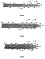
Fig. 4 is a side cross-sectional view of the microwave ablation probe ofFig. 2 ; -
Fig. 5 is a perspective cross-sectional view of the microwave ablation probe having an supply duct according to the present disclosure; and -
Fig. 6 is a perspective cross-sectional view of one embodiment of the microwave ablation probe having an supply duct according to the present disclosure. - Particular embodiments of the present disclosure will be described herein below with reference to the accompanying drawings. In the following description, well-known functions or constructions are not described in detail to avoid obscuring the present disclosure in unnecessary detail.
-
Fig.1 shows amicrowave ablation system 10 which includes amicrowave ablation probe 12 coupled to amicrowave generator 14 via a flexiblecoaxial cable 16, which is, in turn, coupled to aconnector 18 of thegenerator 14. Thegenerator 14 is configured to provide microwave energy at an operational frequency from about 500 MHz to about 2500 MHz. - During microwave ablation, the
probe 12 is inserted into tissue and microwave energy is supplied thereto. As tissue surrounding theprobe 12 is ablated, the tissue undergoes desiccation and denaturization which results in a drop of the effective dielectric constant of the tissue (i.e., increase in impedance). The drop in the effective dielectric constant, in turn, lengthens the wavelength of the microwave energy. Since the probe length is held constant during ablation, the increase in the wavelength results in the increase of the optimal operational frequency of the probe. Thus, at the outset theprobe 12 is at an initial match point - a predetermined operational frequency that increases to a higher frequency as the ablation continues. The higher frequency is determined according to the formula (1), wherein (εr) is the dielectric constant and f is the frequency:
- With respect to liver tissue, in a normal uncooked state, the liver tissue has a dielectric constant of 50 with the operational frequency being 915 MHz. In a cooked state, the liver tissue has a dielectric constant of 25. Substituting these values into the formula (1) provides the lower frequency, which in this case is 1300 MHz. The
probe 12 according to the present disclosure has an operational bandwidth configured to encompass the initial match point as well as the higher frequency. In particular, the bandwidth of theprobe 12 is approximately 40% of the operational frequency. In embodiments, theprobe 12 is loaded with one or more of the following: one or more disks, liquid and/or solid dielectric materials. These materials provide a static envelope around the antenna and act as a buffer between the antenna and the tissue. Use of a liquid dielectric material also allows for active cooling of the antenna during ablation in addition to providing a dielectric buffer. - As shown in
Figs. 2-4 , theprobe 12 includes afeedline 26, achoke 28 and a radiatingportion 30. Thefeedline 26 extends between the distal end of theprobe 12 where thefeedline 26 is coupled to thecable 16, to the radiatingportion 30. Thefeedline 26 is constructed from a coaxial cable having an inner conductor 20 (e.g., wire) surrounded by an insulatingspacer 22 which is then surrounded by an outer conductor 24 (e.g., cylindrical conducting sheath). In one embodiment, thefeedline 26 may have a diameter of 0.085 inches and the insulatingspacer 22 may have a dielectric constant of 1.7. - The
feedline 26 may be flexible or semi-rigid and may be of variable length from a proximal end of the radiatingportion 30 to a distal end of thecable 16 ranging from about 1 to about 10 inches. Theinner conductor 20 and theouter conductor 24 may be constructed from a variety of metals and alloys, such as copper, gold, stainless steel, and the like. Metals may be selected based on a variety of factors, such as conductivity and tensile strength. Thus, although stainless steel has lower conductivity than copper and/or gold, stainless steel provides the necessary strength required to puncture tissue and/or skin. In such cases, the inner andouter conductors - The
choke 28 of theprobe 12 is disposed around thefeedline 26 and includes aninner dielectric layer 32 and an outerconductive layer 34. Thechoke 28 confines the microwave energy from thegenerator 14 to the radiatingportion 30 of theprobe 12 thereby limiting the microwave energy deposition zone length along thefeedline 26. Thechoke 28 is implemented with a quarter wave short by using the outerconductive layer 34 around theouter conductor 24 of thefeedline 26 separated by thedielectric layer 32. Thechoke 28 is shorted to theouter conductor 24 of thefeedline 26 at the proximal end of thechoke 28 by soldering or other means. In embodiments, the length of thechoke 28 may be from a quarter to a full wavelength. Thechoke 28 acts as a high impedance to microwave energy conducted down the outside of thefeedline 26 thereby limiting energy deposition to the end of the probe. In one embodiment, thedielectric layer 32 is formed from a fluoropolymer such as tetrafluorethylene, perfluorpropylene, and the like and has a thickness of 0.005 inches. The outerconductive layer 34 may be formed from a so-called "perfect conductor" material such as a highly conductive metal (e.g., copper). - The
probe 12 further includes atapered end 36 which terminates in atip 38 at the distal end of the radiatingportion 30. Thetapered end 36 allows for insertion of theprobe 12 into tissue with minimal resistance. In cases where the radiatingportion 12 is inserted into a pre-existing opening, thetip 38 may be rounded or flat. Thetapered end 36 may be formed from any type of hard material such as metal and/or plastic. - One embodiment of the
probe 12 is shown inFigs. 2-4 in which theprobe 12 includes one or moreconductive disks 40 loaded therein. Thefeedline 26 extends past the distal end of thechoke 28, with the insulatingspacer 22 and theouter conductor 24 terminating at the start of the radiatingportion 30. Theinner conductor 20 is extruded from thefeedline 26 and extends into the radiatingportion 30 where theinner conductor 20 is centrally disposed. The extruded portion of theinner conductor 20 includes one or more of theconductive disks 40 which are also centrally disposed thereon (i.e., the center of thedisks 40 is on the longitudinal axis). Thedisks 40 are perpendicular to a longitudinal axis defined by theinner conductor 20. In one embodiment, thedisks 40 have a thickness from about 0.01 inches to about 0.02 inches and have a diameter from about 0.04 inches to about the thickness of thefeedline 26, which in one embodiment is 0.085 inches. Thedisks 40 may be of varying size, diameter and thickness, or all of thedisks 40 may be of the same size. Thedisks 40 are spaced on theinner conductor 20 such that the desired bandwidth is obtained. - The
disks 40 divide the radiatingportion 30 into a corresponding number of spaces 42: thespaces 42 between thefeedline 26 and thefirst disk 40, between the first andsecond disks 40, and within thetapered end 36. Thespaces 42 are loaded with a soliddielectric material 44 which is shaped to fill the correspondingspaces 40 to further improve the impedance match between theprobe 12 and thegenerator 14. More specifically, to fill thespaces 42 between thedisks 40, thematerial 44 may be cylinder-shaped having acentral cavity 45 defined therein as illustrated inFig. 3 . The cylinder has an outer diameter being substantially equal to the thickness of thefeedline 26 and the inner diameter being substantially equal to the diameter of theinner conductor 20. To fill thespace 42 at thetapered end 36, thematerial 44 may be cone-shaped. In one embodiment, thematerial 44 has a dielectric constant of from about 2.5 and 30 and may be made from a ceramic material, such as alumina ceramic or a plastic material, such as a polyamide plastic (e.g., VESPEL® available from DuPont of Wilmington, Delaware). -
Fig. 5 illustrates another embodiment of themicrowave ablation probe 12. Theprobe 12 includes the radiatingportion 30 coupled to thefeedline 26 which is covered by thechoke 28. Thefeedline 26 includes theinner conductor 20 surrounded by the insulatingspacer 22 which is then surrounded by theouter conductor 24. Theinner conductor 20 of thefeedline 26 includes one ormore disks 40 perpendicularly disposed thereon. Thefeedline 26, at least a portion of thechoke 28, and the radiatingportion 30 are enclosed within acavity 43 formed by a moisture-impervious housing 46. Theprobe 12 also includes one ormore supply tubes 48 that supply adielectric fluid 45, such as saline solution and the like, into thecavity 43. Thedielectric fluid 45 provides for an impedance match as well as cools theprobe 12. Thedielectric fluid 45 may be stored in a supply tank (not explicitly shown) and may be supplied by a pump (e.g., peristaltic pump) into thecavity 43. Thesupply tube 48 is constructed from a flexible material such as polyamide polymer. -
Fig. 6 shows another embodiment of theprobe 12 which includes thechoke 28 enclosing the feedline disposed within the radiatingportion 30. Theradiation portion 30 includes an unbalanced folded-dipole antenna 50 which includes the extrudedinner conductor 20 as a central arm and one or moreouter arms 52 which extend from and are coupled to the distal end ofinner conductor 20. Theouter arms 52 are also coupled to theouter conductor 24 of thefeedline 26. Theouter arms 52 are coupled to theinner conductor 20 and theouter conductor 24 by soldering and/or other methods which allow for conductive coupling of metals. The length of the folded-dipole antenna 50 is between a quarter and a full wavelength of the operating microwave energy, effectively providing for an optimum impedance match. - The
radiation portion 30, thefeedline 26 and thechoke 28 are disposed within thecavity 43 defined by thehousing 46. Thecavity 43 also includes one ormore supply tubes 48 which supply the fluid 45 thereto. In embodiments shown inFigs. 5 and 6 , thedielectric fluid 45 may be circulated through thecavity 43 by continually supplying the fluid 45 through thesupply tube 48 and withdrawing the fluid using a return tube (not explicitly shown). - The
probe 12 according to the present disclosure has a broadband range encompassing the frequency variation encountered during ablation due to tissue state changes. Theprobe 12 is configured to maintain an impedance match to thegenerator 14 and thecable 16 which provides for improved microwave deposition and penetration depth that are maintained throughout the course of an ablation despite tissue changes. - The described embodiments of the present disclosure are intended to be illustrative rather than restrictive, and are not intended to represent every embodiment of the present disclosure. Various modifications and variations can be made without departing from the spirit or scope of the disclosure as set forth in the following claims both literally and in equivalents recognized in law.
Claims (15)
- A microwave ablation probe for providing microwave energy to tissue, the probe comprising:a feedline including an inner conductor, an insulating spacer and an outer conductor;a radiation portion including at least a portion of the inner conductor that is centrally disposed therein, the radiation portion including at least one conductive disk disposed on the portion of the inner conductor that defines at least one space; anda dielectric material disposed within the at least one space.
- A microwave ablation probe according to claim 1, further including a choke disposed around at least a portion of the feedline and configured to confine the microwave energy to the radiating portion, the choke including an inner dielectric layer and an outer conductive layer.
- A microwave ablation probe according to any preceding claim, wherein the dielectric material is solid and is shaped as a cylinder having a central cavity defined therein, the cylinder has an outer diameter being substantially equal to the diameter of the feedline and an inner diameter being substantially equal to the diameter of the inner conductor.
- A microwave ablation probe according to any preceding claim, further including a tapered end having a tip disposed at a distal end of the radiating portion.
- A microwave ablation probe according to claim 4, wherein the dielectric material is solid and is shaped as a cone configured to fit within the tapered end.
- A microwave ablation probe according to any proceeding claim, wherein the dielectric material is selected from the group consisting of a ceramic and a plastic.
- A microwave ablation probe according to any proceeding claim, further comprising at least one supply tube configured to supply the dielectric material into the at least one space.
- A microwave ablation probe according to claim 7, wherein the dielectric material is a liquid cooling dielectric material selected from a group consisting of water and a saline solution.
- A microwave ablation probe for providing microwave energy to tissue, the probe comprising:a feedline including an inner conductor, an insulating spacer and an outer conductor;a radiation portion including a folded-dipole antenna constructed from at least a portion of the inner conductor and at least one outer arm coupled to the outer conductor, the radiation portion further including a dielectric material disposed around the folded-dipole antenna.
- A microwave ablation probe according to claim 9, further including a choke disposed around at least a portion of the feedline and configured to confine the microwave energy to the radiating portion, the choke including an inner dielectric layer and an outer conductive layer.
- A microwave ablation probe according to claim 9 or 10, further including a tapered end having a tip disposed at a distal end of the radiating portion.
- A microwave ablation probe according to claim 9, 10 or 11, wherein the dielectric material is a liquid cooling dielectric material.
- A microwave ablation probe according to claim 12, further including at least one supply tube configured to supply the liquid cooling dielectric material into the radiation portion.
- A microwave ablation probe according to claim 12 or 13, wherein the liquid cooling dielectric material is selected from a group consisting of water and a saline solution.
- A microwave ablation probe according to claim 9, 10, 11, 12, 13, 14 or 15, wherein the dielectric material is solid and is selected from a group consisting of a ceramic and a plastic.
Applications Claiming Priority (1)
| Application Number | Priority Date | Filing Date | Title |
|---|---|---|---|
| US11/823,639 US20090005766A1 (en) | 2007-06-28 | 2007-06-28 | Broadband microwave applicator |
Publications (3)
| Publication Number | Publication Date |
|---|---|
| EP2008604A2 true EP2008604A2 (en) | 2008-12-31 |
| EP2008604A3 EP2008604A3 (en) | 2009-12-02 |
| EP2008604B1 EP2008604B1 (en) | 2012-12-26 |
Family
ID=39789994
Family Applications (1)
| Application Number | Title | Priority Date | Filing Date |
|---|---|---|---|
| EP08011705A Expired - Fee Related EP2008604B1 (en) | 2007-06-28 | 2008-06-27 | Broadband microwave applicator |
Country Status (5)
| Country | Link |
|---|---|
| US (2) | US20090005766A1 (en) |
| EP (1) | EP2008604B1 (en) |
| JP (1) | JP5335301B2 (en) |
| AU (1) | AU2008202845B2 (en) |
| CA (1) | CA2636393C (en) |
Cited By (8)
| Publication number | Priority date | Publication date | Assignee | Title |
|---|---|---|---|---|
| WO2010121047A2 (en) | 2009-04-15 | 2010-10-21 | Medwaves, Inc. | Radio frequency based ablation system and method with dielectric transformer |
| EP2361582A1 (en) * | 2010-02-19 | 2011-08-31 | Vivant Medical, Inc. | Ablation devices with dual operating frequencies, systems including same, and methods of adjusting ablation volume using same |
| EP2386261A3 (en) * | 2010-05-11 | 2011-12-28 | Vivant Medical, Inc. | Electrosurgical devices with balun structure for air exposure of antenna radiating section |
| US9757197B2 (en) | 2009-10-06 | 2017-09-12 | Angiodynamics, Inc. | Medical devices and pumps therefor |
| US9888956B2 (en) | 2013-01-22 | 2018-02-13 | Angiodynamics, Inc. | Integrated pump and generator device and method of use |
| GB2575484A (en) * | 2018-07-12 | 2020-01-15 | Creo Medical Ltd | Electrosurgical instrument |
| US10660691B2 (en) | 2015-10-07 | 2020-05-26 | Angiodynamics, Inc. | Multiple use subassembly with integrated fluid delivery system for use with single or dual-lumen peristaltic tubing |
| GB2579561A (en) * | 2018-12-03 | 2020-07-01 | Creo Medical Ltd | Electrosurgical instrument |
Families Citing this family (49)
| Publication number | Priority date | Publication date | Assignee | Title |
|---|---|---|---|---|
| US10363092B2 (en) | 2006-03-24 | 2019-07-30 | Neuwave Medical, Inc. | Transmission line with heat transfer ability |
| US10376314B2 (en) | 2006-07-14 | 2019-08-13 | Neuwave Medical, Inc. | Energy delivery systems and uses thereof |
| US11389235B2 (en) | 2006-07-14 | 2022-07-19 | Neuwave Medical, Inc. | Energy delivery systems and uses thereof |
| US8332435B2 (en) | 2006-10-03 | 2012-12-11 | Salesforce.Com, Inc. | Method and system for customizing a user interface to an on-demand database service |
| US8552915B2 (en) | 2009-06-19 | 2013-10-08 | Covidien Lp | Microwave ablation antenna radiation detector |
| DK2459096T3 (en) | 2009-07-28 | 2015-01-19 | Neuwave Medical Inc | ablation device |
| US8328799B2 (en) * | 2009-08-05 | 2012-12-11 | Vivant Medical, Inc. | Electrosurgical devices having dielectric loaded coaxial aperture with distally positioned resonant structure |
| AU2015201444B2 (en) * | 2009-08-05 | 2017-04-20 | Covidien Lp | Electrosurgical devices having dielectric loaded coaxial aperture with distally positioned resonant structure and method of manufacturing same |
| US8343145B2 (en) * | 2009-09-28 | 2013-01-01 | Vivant Medical, Inc. | Microwave surface ablation using conical probe |
| US8430871B2 (en) | 2009-10-28 | 2013-04-30 | Covidien Lp | System and method for monitoring ablation size |
| US8469953B2 (en) | 2009-11-16 | 2013-06-25 | Covidien Lp | Twin sealing chamber hub |
| US8551083B2 (en) | 2009-11-17 | 2013-10-08 | Bsd Medical Corporation | Microwave coagulation applicator and system |
| US8414570B2 (en) * | 2009-11-17 | 2013-04-09 | Bsd Medical Corporation | Microwave coagulation applicator and system |
| US9993294B2 (en) * | 2009-11-17 | 2018-06-12 | Perseon Corporation | Microwave coagulation applicator and system with fluid injection |
| US20110125148A1 (en) * | 2009-11-17 | 2011-05-26 | Turner Paul F | Multiple Frequency Energy Supply and Coagulation System |
| US8491579B2 (en) * | 2010-02-05 | 2013-07-23 | Covidien Lp | Electrosurgical devices with choke shorted to biological tissue |
| EP3804651A1 (en) | 2010-05-03 | 2021-04-14 | Neuwave Medical, Inc. | Energy delivery systems |
| US8932281B2 (en) * | 2011-01-05 | 2015-01-13 | Covidien Lp | Energy-delivery devices with flexible fluid-cooled shaft, inflow/outflow junctions suitable for use with same, and systems including same |
| CN107224325B (en) | 2011-12-21 | 2020-09-01 | 纽华沃医药公司 | Energy delivery system and use thereof |
| US9901398B2 (en) | 2012-06-29 | 2018-02-27 | Covidien Lp | Microwave antenna probes |
| US9259269B2 (en) | 2012-08-07 | 2016-02-16 | Covidien Lp | Microwave ablation catheter and method of utilizing the same |
| US9668802B2 (en) | 2012-10-02 | 2017-06-06 | Covidien Lp | Devices and methods for optical detection of tissue contact |
| US9993283B2 (en) | 2012-10-02 | 2018-06-12 | Covidien Lp | Selectively deformable ablation device |
| US9901399B2 (en) | 2012-12-17 | 2018-02-27 | Covidien Lp | Ablation probe with tissue sensing configuration |
| CN103006316B (en) * | 2013-01-09 | 2015-11-25 | 中国科学技术大学 | A kind of cold and hot cutter |
| CN103006315B (en) * | 2013-01-09 | 2015-05-27 | 中国科学技术大学 | Freezing-heating tool |
| EP3378429B1 (en) * | 2013-03-29 | 2020-08-19 | Covidien LP | Method of manufacturing of coaxial microwave ablation applicators |
| US10624697B2 (en) | 2014-08-26 | 2020-04-21 | Covidien Lp | Microwave ablation system |
| US10813691B2 (en) * | 2014-10-01 | 2020-10-27 | Covidien Lp | Miniaturized microwave ablation assembly |
| CN104323856B (en) | 2014-11-11 | 2017-07-18 | 南京维京九洲医疗器械研发中心 | Without magnetic water-cooled microwave ablation needle manufacture method |
| US20170014638A1 (en) * | 2015-07-13 | 2017-01-19 | Symple Surgical, Inc. | Cable with microwave emitter |
| US20170014639A1 (en) * | 2015-07-13 | 2017-01-19 | Symple Surgical, Inc. | Cable with microwave emitter |
| WO2017075067A1 (en) | 2015-10-26 | 2017-05-04 | Neuwave Medical, Inc. | Energy delivery systems and uses thereof |
| GB2545465A (en) * | 2015-12-17 | 2017-06-21 | Creo Medical Ltd | Electrosurgical probe for delivering microwave energy |
| US10813692B2 (en) | 2016-02-29 | 2020-10-27 | Covidien Lp | 90-degree interlocking geometry for introducer for facilitating deployment of microwave radiating catheter |
| EP3808302B1 (en) | 2016-04-15 | 2023-07-26 | Neuwave Medical, Inc. | System for energy delivery |
| US11065053B2 (en) | 2016-08-02 | 2021-07-20 | Covidien Lp | Ablation cable assemblies and a method of manufacturing the same |
| US10461432B1 (en) * | 2016-08-02 | 2019-10-29 | Arizona Board Of Regents On Behalf Of The University Of Arizona | Collapsible feed structures for reflector antennas |
| US10376309B2 (en) | 2016-08-02 | 2019-08-13 | Covidien Lp | Ablation cable assemblies and a method of manufacturing the same |
| US11197715B2 (en) | 2016-08-02 | 2021-12-14 | Covidien Lp | Ablation cable assemblies and a method of manufacturing the same |
| US11439809B2 (en) | 2017-09-21 | 2022-09-13 | Covidien Lp | Systems, devices, and methods for ovarian denervation |
| US11672596B2 (en) | 2018-02-26 | 2023-06-13 | Neuwave Medical, Inc. | Energy delivery devices with flexible and adjustable tips |
| GB2573823A (en) * | 2018-05-19 | 2019-11-20 | Creo Medical Ltd | Electrosurgical ablation instrument |
| CN109009426B (en) * | 2018-09-03 | 2023-10-27 | 安徽赢创医疗科技有限公司 | Microwave thermal condenser system |
| GB2578576B (en) * | 2018-10-30 | 2022-08-24 | Creo Medical Ltd | Electrosurgical instrument |
| WO2020163253A1 (en) * | 2019-02-06 | 2020-08-13 | Covidien Lp | Internally cooled ceramic element for a microwave ablation radiator |
| US11832879B2 (en) | 2019-03-08 | 2023-12-05 | Neuwave Medical, Inc. | Systems and methods for energy delivery |
| CN110523003A (en) * | 2019-09-23 | 2019-12-03 | 南京臻泰微波科技有限公司 | A kind of tumor microwave ablation needle without water cooling |
| US11786303B2 (en) * | 2021-03-19 | 2023-10-17 | Quicker-Instrument Inc. | Microwave ablation probe |
Family Cites Families (99)
| Publication number | Priority date | Publication date | Assignee | Title |
|---|---|---|---|---|
| US4140130A (en) * | 1977-05-31 | 1979-02-20 | Storm Iii Frederick K | Electrode structure for radio frequency localized heating of tumor bearing tissue |
| US4311154A (en) * | 1979-03-23 | 1982-01-19 | Rca Corporation | Nonsymmetrical bulb applicator for hyperthermic treatment of the body |
| US5097844A (en) * | 1980-04-02 | 1992-03-24 | Bsd Medical Corporation | Hyperthermia apparatus having three-dimensional focusing |
| US4798215A (en) * | 1984-03-15 | 1989-01-17 | Bsd Medical Corporation | Hyperthermia apparatus |
| FR2505495A1 (en) * | 1981-05-05 | 1982-11-12 | Centre Nat Rech Scient | METHOD AND DEVICES FOR MEASURING TEMPERATURE OF A MICROWAVE BODY |
| US5370675A (en) * | 1992-08-12 | 1994-12-06 | Vidamed, Inc. | Medical probe device and method |
| FR2546409B1 (en) * | 1983-05-26 | 1988-05-13 | Cgr Mev | HYPERTHERMIA APPARATUS |
| US4800899A (en) * | 1984-10-22 | 1989-01-31 | Microthermia Technology, Inc. | Apparatus for destroying cells in tumors and the like |
| US4658836A (en) * | 1985-06-28 | 1987-04-21 | Bsd Medical Corporation | Body passage insertable applicator apparatus for electromagnetic |
| IL78755A0 (en) * | 1986-05-12 | 1986-08-31 | Biodan Medical Systems Ltd | Applicator for insertion into a body opening for medical purposes |
| US5097845A (en) * | 1987-10-15 | 1992-03-24 | Labthermics Technologies | Microwave hyperthermia probe |
| US4841988A (en) * | 1987-10-15 | 1989-06-27 | Marquette Electronics, Inc. | Microwave hyperthermia probe |
| US4934365A (en) * | 1988-06-30 | 1990-06-19 | Massachusetts Institute Of Technology | Non-invasive hyperthermia method and apparatus |
| FR2639238B1 (en) * | 1988-11-21 | 1991-02-22 | Technomed Int Sa | APPARATUS FOR SURGICAL TREATMENT OF TISSUES BY HYPERTHERMIA, PREFERABLY THE PROSTATE, COMPRISING MEANS OF THERMAL PROTECTION COMPRISING PREFERABLY RADIOREFLECTIVE SCREEN MEANS |
| FR2693116B1 (en) * | 1992-07-06 | 1995-04-28 | Technomed Int Sa | Urethral probe and apparatus for the therapeutic treatment of prostate tissue by thermotherapy. |
| DE3926934A1 (en) * | 1989-08-16 | 1991-02-21 | Deutsches Krebsforsch | HYPERTHERMIC MICROWAVE APPLICATOR FOR WARMING A LIMITED ENVIRONMENT IN A DISSIPATIVE MEDIUM |
| US5122137A (en) * | 1990-04-27 | 1992-06-16 | Boston Scientific Corporation | Temperature controlled rf coagulation |
| US5221269A (en) * | 1990-10-15 | 1993-06-22 | Cook Incorporated | Guide for localizing a nonpalpable breast lesion |
| US5531662A (en) * | 1990-12-17 | 1996-07-02 | Microwave Medical Systems, Inc. | Dual mode microwave/ionizing probe |
| US5301687A (en) * | 1991-06-06 | 1994-04-12 | Trustees Of Dartmouth College | Microwave applicator for transurethral hyperthermia |
| US5417210A (en) * | 1992-05-27 | 1995-05-23 | International Business Machines Corporation | System and method for augmentation of endoscopic surgery |
| US5413588A (en) * | 1992-03-06 | 1995-05-09 | Urologix, Inc. | Device and method for asymmetrical thermal therapy with helical dipole microwave antenna |
| US5314466A (en) * | 1992-04-13 | 1994-05-24 | Ep Technologies, Inc. | Articulated unidirectional microwave antenna systems for cardiac ablation |
| US5281217A (en) * | 1992-04-13 | 1994-01-25 | Ep Technologies, Inc. | Steerable antenna systems for cardiac ablation that minimize tissue damage and blood coagulation due to conductive heating patterns |
| US5275597A (en) * | 1992-05-18 | 1994-01-04 | Baxter International Inc. | Percutaneous transluminal catheter and transmitter therefor |
| WO1994002077A2 (en) * | 1992-07-15 | 1994-02-03 | Angelase, Inc. | Ablation catheter system |
| US5720718A (en) * | 1992-08-12 | 1998-02-24 | Vidamed, Inc. | Medical probe apparatus with enhanced RF, resistance heating, and microwave ablation capabilities |
| US5383922A (en) * | 1993-03-15 | 1995-01-24 | Medtronic, Inc. | RF lead fixation and implantable lead |
| US5405346A (en) * | 1993-05-14 | 1995-04-11 | Fidus Medical Technology Corporation | Tunable microwave ablation catheter |
| WO1994028809A1 (en) * | 1993-06-10 | 1994-12-22 | Imran Mir A | Transurethral radio frequency ablation apparatus |
| GB9315473D0 (en) * | 1993-07-27 | 1993-09-08 | Chemring Ltd | Treatment apparatus |
| US5545193A (en) * | 1993-10-15 | 1996-08-13 | Ep Technologies, Inc. | Helically wound radio-frequency emitting electrodes for creating lesions in body tissue |
| US5507743A (en) * | 1993-11-08 | 1996-04-16 | Zomed International | Coiled RF electrode treatment apparatus |
| US6569159B1 (en) * | 1993-11-08 | 2003-05-27 | Rita Medical Systems, Inc. | Cell necrosis apparatus |
| US6530922B2 (en) * | 1993-12-15 | 2003-03-11 | Sherwood Services Ag | Cluster ablation electrode system |
| US6056744A (en) * | 1994-06-24 | 2000-05-02 | Conway Stuart Medical, Inc. | Sphincter treatment apparatus |
| EP1011495B1 (en) * | 1995-05-04 | 2005-11-09 | Sherwood Services AG | Cool-tip electrode thermosurgery system |
| US5628770A (en) * | 1995-06-06 | 1997-05-13 | Urologix, Inc. | Devices for transurethral thermal therapy |
| US6235023B1 (en) * | 1995-08-15 | 2001-05-22 | Rita Medical Systems, Inc. | Cell necrosis apparatus |
| US6059780A (en) * | 1995-08-15 | 2000-05-09 | Rita Medical Systems, Inc. | Multiple antenna ablation apparatus and method with cooling element |
| US6080150A (en) * | 1995-08-15 | 2000-06-27 | Rita Medical Systems, Inc. | Cell necrosis apparatus |
| US6122549A (en) * | 1996-08-13 | 2000-09-19 | Oratec Interventions, Inc. | Apparatus for treating intervertebral discs with resistive energy |
| US5938692A (en) * | 1996-03-26 | 1999-08-17 | Urologix, Inc. | Voltage controlled variable tuning antenna |
| US6289249B1 (en) * | 1996-04-17 | 2001-09-11 | The United States Of America As Represented By The Administrator Of The National Aeronautics And Space Administration | Transcatheter microwave antenna |
| US6047216A (en) * | 1996-04-17 | 2000-04-04 | The United States Of America Represented By The Administrator Of The National Aeronautics And Space Administration | Endothelium preserving microwave treatment for atherosclerosis |
| US5904709A (en) * | 1996-04-17 | 1999-05-18 | The United States Of America As Represented By The Administrator Of The National Aeronautics And Space Administration | Microwave treatment for cardiac arrhythmias |
| AUPN957296A0 (en) * | 1996-04-30 | 1996-05-23 | Cardiac Crc Nominees Pty Limited | A system for simultaneous unipolar multi-electrode ablation |
| AU2931897A (en) * | 1996-05-06 | 1997-11-26 | Thermal Therapeutics, Inc. | Transcervical intrauterine applicator for intrauterine hyperthermia |
| US5980535A (en) * | 1996-09-30 | 1999-11-09 | Picker International, Inc. | Apparatus for anatomical tracking |
| US5741249A (en) * | 1996-10-16 | 1998-04-21 | Fidus Medical Technology Corporation | Anchoring tip assembly for microwave ablation catheter |
| US5897554A (en) * | 1997-03-01 | 1999-04-27 | Irvine Biomedical, Inc. | Steerable catheter having a loop electrode |
| US6063078A (en) * | 1997-03-12 | 2000-05-16 | Medtronic, Inc. | Method and apparatus for tissue ablation |
| US6245064B1 (en) * | 1997-07-08 | 2001-06-12 | Atrionix, Inc. | Circumferential ablation device assembly |
| US6358246B1 (en) * | 1999-06-25 | 2002-03-19 | Radiotherapeutics Corporation | Method and system for heating solid tissue |
| US6176857B1 (en) * | 1997-10-22 | 2001-01-23 | Oratec Interventions, Inc. | Method and apparatus for applying thermal energy to tissue asymmetrically |
| US6031375A (en) * | 1997-11-26 | 2000-02-29 | The Johns Hopkins University | Method of magnetic resonance analysis employing cylindrical coordinates and an associated apparatus |
| US6051019A (en) * | 1998-01-23 | 2000-04-18 | Del Mar Medical Technologies, Inc. | Selective organ hypothermia method and apparatus |
| WO1999065410A1 (en) * | 1998-06-19 | 1999-12-23 | Endocare, Inc. | Sheath, cryoprobe, and methods for use |
| WO2000009208A1 (en) * | 1998-08-14 | 2000-02-24 | K.U. Leuven Research & Development | Cooled-wet electrode |
| US6016811A (en) * | 1998-09-01 | 2000-01-25 | Fidus Medical Technology Corporation | Method of using a microwave ablation catheter with a loop configuration |
| US6251128B1 (en) * | 1998-09-01 | 2001-06-26 | Fidus Medical Technology Corporation | Microwave ablation catheter with loop configuration |
| US6245062B1 (en) * | 1998-10-23 | 2001-06-12 | Afx, Inc. | Directional reflector shield assembly for a microwave ablation instrument |
| US6176856B1 (en) * | 1998-12-18 | 2001-01-23 | Eclipse Surgical Technologies, Inc | Resistive heating system and apparatus for improving blood flow in the heart |
| US6181970B1 (en) * | 1999-02-09 | 2001-01-30 | Kai Technologies, Inc. | Microwave devices for medical hyperthermia, thermotherapy and diagnosis |
| US6233490B1 (en) * | 1999-02-09 | 2001-05-15 | Kai Technologies, Inc. | Microwave antennas for medical hyperthermia, thermotherapy and diagnosis |
| US6217528B1 (en) * | 1999-02-11 | 2001-04-17 | Scimed Life Systems, Inc. | Loop structure having improved tissue contact capability |
| US20020022836A1 (en) * | 1999-03-05 | 2002-02-21 | Gyrus Medical Limited | Electrosurgery system |
| US6375606B1 (en) * | 1999-03-17 | 2002-04-23 | Stereotaxis, Inc. | Methods of and apparatus for treating vascular defects |
| US6306132B1 (en) * | 1999-06-17 | 2001-10-23 | Vivant Medical | Modular biopsy and microwave ablation needle delivery apparatus adapted to in situ assembly and method of use |
| US20030130657A1 (en) * | 1999-08-05 | 2003-07-10 | Tom Curtis P. | Devices for applying energy to tissue |
| US6230060B1 (en) * | 1999-10-22 | 2001-05-08 | Daniel D. Mawhinney | Single integrated structural unit for catheter incorporating a microwave antenna |
| US6347251B1 (en) * | 1999-12-23 | 2002-02-12 | Tianquan Deng | Apparatus and method for microwave hyperthermia and acupuncture |
| US6564806B1 (en) * | 2000-02-18 | 2003-05-20 | Thomas J. Fogarty | Device for accurately marking tissue |
| JP5090600B2 (en) * | 2000-02-18 | 2012-12-05 | トーマス ジェイ. フォガーティー, | Improved device for accurately marking tissues |
| US6722371B1 (en) * | 2000-02-18 | 2004-04-20 | Thomas J. Fogarty | Device for accurately marking tissue |
| US6723091B2 (en) * | 2000-02-22 | 2004-04-20 | Gyrus Medical Limited | Tissue resurfacing |
| US6725080B2 (en) * | 2000-03-01 | 2004-04-20 | Surgical Navigation Technologies, Inc. | Multiple cannula image guided tool for image guided procedures |
| US6652517B1 (en) * | 2000-04-25 | 2003-11-25 | Uab Research Foundation | Ablation catheter, system, and method of use thereof |
| US6699241B2 (en) * | 2000-08-11 | 2004-03-02 | Northeastern University | Wide-aperture catheter-based microwave cardiac ablation antenna |
| DE10102254A1 (en) * | 2001-01-19 | 2002-08-08 | Celon Ag Medical Instruments | Device for the electrothermal treatment of the human or animal body |
| ITPI20010006A1 (en) * | 2001-01-31 | 2002-07-31 | Cnr Consiglio Naz Delle Ricer | INTERSTITIAL ANTENNA WITH MINIATURIZED CHOKE FOR MICROWAVE HYPERTEMIA APPLICATIONS IN MEDICINE AND SURGERY |
| US6611699B2 (en) * | 2001-06-28 | 2003-08-26 | Scimed Life Systems, Inc. | Catheter with an irrigated composite tip electrode |
| WO2003024309A2 (en) * | 2001-09-19 | 2003-03-27 | Urologix, Inc. | Microwave ablation device |
| US20030078573A1 (en) * | 2001-10-18 | 2003-04-24 | Csaba Truckai | Electrosurgical working end for controlled energy delivery |
| US7128739B2 (en) * | 2001-11-02 | 2006-10-31 | Vivant Medical, Inc. | High-strength microwave antenna assemblies and methods of use |
| US6878147B2 (en) * | 2001-11-02 | 2005-04-12 | Vivant Medical, Inc. | High-strength microwave antenna assemblies |
| US6706040B2 (en) * | 2001-11-23 | 2004-03-16 | Medlennium Technologies, Inc. | Invasive therapeutic probe |
| US7697972B2 (en) * | 2002-11-19 | 2010-04-13 | Medtronic Navigation, Inc. | Navigation system for cardiac therapies |
| US6957108B2 (en) * | 2003-06-02 | 2005-10-18 | Bsd Medical Corporation | Invasive microwave antenna array for hyperthermia and brachytherapy |
| GB2403148C2 (en) * | 2003-06-23 | 2013-02-13 | Microsulis Ltd | Radiation applicator |
| US7311703B2 (en) * | 2003-07-18 | 2007-12-25 | Vivant Medical, Inc. | Devices and methods for cooling microwave antennas |
| US7229437B2 (en) * | 2003-09-22 | 2007-06-12 | St. Jude Medical, Atrial Fibrillation Division, Inc. | Medical device having integral traces and formed electrodes |
| US7244254B2 (en) * | 2004-04-29 | 2007-07-17 | Micrablate | Air-core microwave ablation antennas |
| GB2415630C2 (en) * | 2004-07-02 | 2007-03-22 | Microsulis Ltd | Radiation applicator and method of radiating tissue |
| GB2434314B (en) * | 2006-01-03 | 2011-06-15 | Microsulis Ltd | Microwave applicator with dipole antenna |
| JP2007029457A (en) * | 2005-07-27 | 2007-02-08 | Univ Nihon | Coaxial antenna for microwave coagulation therapy |
| US8369950B2 (en) * | 2005-10-28 | 2013-02-05 | Cardiac Pacemakers, Inc. | Implantable medical device with fractal antenna |
| US7826904B2 (en) * | 2006-02-07 | 2010-11-02 | Angiodynamics, Inc. | Interstitial microwave system and method for thermal treatment of diseases |
| US7864129B2 (en) * | 2006-04-04 | 2011-01-04 | Namiki Seimitsu Houseki Kabushiki Kaisha | Radio frequency medical treatment device and system and usage method thereof |
-
2007
- 2007-06-28 US US11/823,639 patent/US20090005766A1/en not_active Abandoned
-
2008
- 2008-06-26 CA CA2636393A patent/CA2636393C/en not_active Expired - Fee Related
- 2008-06-27 JP JP2008169614A patent/JP5335301B2/en not_active Expired - Fee Related
- 2008-06-27 AU AU2008202845A patent/AU2008202845B2/en not_active Ceased
- 2008-06-27 EP EP08011705A patent/EP2008604B1/en not_active Expired - Fee Related
-
2013
- 2013-08-01 US US13/957,087 patent/US20130317495A1/en not_active Abandoned
Non-Patent Citations (1)
| Title |
|---|
| None |
Cited By (19)
| Publication number | Priority date | Publication date | Assignee | Title |
|---|---|---|---|---|
| US8934989B2 (en) | 2009-04-15 | 2015-01-13 | Medwaves, Inc. | Radio frequency based ablation system and method with dielectric transformer |
| WO2010121047A2 (en) | 2009-04-15 | 2010-10-21 | Medwaves, Inc. | Radio frequency based ablation system and method with dielectric transformer |
| EP2419040A2 (en) * | 2009-04-15 | 2012-02-22 | Medwaves, Inc. | Radio frequency based ablation system and method with dielectric transformer |
| EP2419040A4 (en) * | 2009-04-15 | 2013-01-23 | Medwaves Inc | Radio frequency based ablation system and method with dielectric transformer |
| EP2419040B1 (en) * | 2009-04-15 | 2014-06-11 | Medwaves, Inc. | Rf ablation system comprising a dielectric transformer |
| US9757197B2 (en) | 2009-10-06 | 2017-09-12 | Angiodynamics, Inc. | Medical devices and pumps therefor |
| US9724159B2 (en) | 2010-02-19 | 2017-08-08 | Covidien Lp | Ablation devices with dual operating frequencies, systems including same, and methods of adjusting ablation volume using same |
| US8968288B2 (en) | 2010-02-19 | 2015-03-03 | Covidien Lp | Ablation devices with dual operating frequencies, systems including same, and methods of adjusting ablation volume using same |
| EP2361582A1 (en) * | 2010-02-19 | 2011-08-31 | Vivant Medical, Inc. | Ablation devices with dual operating frequencies, systems including same, and methods of adjusting ablation volume using same |
| EP3281597A1 (en) * | 2010-02-19 | 2018-02-14 | Covidien LP | Ablation devices with dual operating frequencies, systems including same, and methods of adjusting ablation volume using same |
| US10987152B2 (en) | 2010-02-19 | 2021-04-27 | Covidien Lp | Ablation devices with dual operating frequencies, systems including same, and methods of adjusting ablation volume using same |
| EP2386261A3 (en) * | 2010-05-11 | 2011-12-28 | Vivant Medical, Inc. | Electrosurgical devices with balun structure for air exposure of antenna radiating section |
| US9888963B2 (en) | 2010-05-11 | 2018-02-13 | Covidien Lp | Electrosurgical devices with balun structure for air exposure of antenna radiating section and method of directing energy to tissue using same |
| US10966784B2 (en) | 2010-05-11 | 2021-04-06 | Covidien Lp | Electrosurgical devices with balun structure |
| US9888956B2 (en) | 2013-01-22 | 2018-02-13 | Angiodynamics, Inc. | Integrated pump and generator device and method of use |
| US10660691B2 (en) | 2015-10-07 | 2020-05-26 | Angiodynamics, Inc. | Multiple use subassembly with integrated fluid delivery system for use with single or dual-lumen peristaltic tubing |
| GB2575484A (en) * | 2018-07-12 | 2020-01-15 | Creo Medical Ltd | Electrosurgical instrument |
| GB2579561A (en) * | 2018-12-03 | 2020-07-01 | Creo Medical Ltd | Electrosurgical instrument |
| GB2579561B (en) * | 2018-12-03 | 2022-10-19 | Creo Medical Ltd | Electrosurgical instrument |
Also Published As
| Publication number | Publication date |
|---|---|
| EP2008604B1 (en) | 2012-12-26 |
| US20090005766A1 (en) | 2009-01-01 |
| CA2636393A1 (en) | 2008-12-28 |
| AU2008202845B2 (en) | 2013-10-17 |
| JP5335301B2 (en) | 2013-11-06 |
| CA2636393C (en) | 2019-03-12 |
| EP2008604A3 (en) | 2009-12-02 |
| JP2009006150A (en) | 2009-01-15 |
| US20130317495A1 (en) | 2013-11-28 |
| AU2008202845A1 (en) | 2009-01-15 |
Similar Documents
| Publication | Publication Date | Title |
|---|---|---|
| EP2008604B1 (en) | Broadband microwave applicator | |
| US9439730B2 (en) | Dual-band dipole microwave ablation antenna | |
| US10363096B2 (en) | Method for constructing a dipole antenna | |
| US9192440B2 (en) | Electrosurgical devices with choke shorted to biological tissue | |
| EP2281522B1 (en) | Electrosurgical devices having dielectric loaded coaxial aperture with distally positioned resonant structure and method of manufacturing the same | |
| US20100045559A1 (en) | Dual-Band Dipole Microwave Ablation Antenna | |
| EP2286754B1 (en) | Surface ablation antenna with dielectric loading | |
| US8608731B2 (en) | Leaky-wave antennas for medical applications | |
| AU2017219068B2 (en) | Dual-band dipole microwave ablation antenna | |
| AU2013273707B2 (en) | Dual-band dipole microwave ablation antenna |
Legal Events
| Date | Code | Title | Description |
|---|---|---|---|
| PUAI | Public reference made under article 153(3) epc to a published international application that has entered the european phase |
Free format text: ORIGINAL CODE: 0009012 |
|
| AK | Designated contracting states |
Kind code of ref document: A2 Designated state(s): AT BE BG CH CY CZ DE DK EE ES FI FR GB GR HR HU IE IS IT LI LT LU LV MC MT NL NO PL PT RO SE SI SK TR |
|
| AX | Request for extension of the european patent |
Extension state: AL BA MK RS |
|
| PUAL | Search report despatched |
Free format text: ORIGINAL CODE: 0009013 |
|
| AK | Designated contracting states |
Kind code of ref document: A3 Designated state(s): AT BE BG CH CY CZ DE DK EE ES FI FR GB GR HR HU IE IS IT LI LT LU LV MC MT NL NO PL PT RO SE SI SK TR |
|
| AX | Request for extension of the european patent |
Extension state: AL BA MK RS |
|
| 17P | Request for examination filed |
Effective date: 20100518 |
|
| 17Q | First examination report despatched |
Effective date: 20100614 |
|
| AKX | Designation fees paid |
Designated state(s): DE ES FR GB IE IT |
|
| GRAP | Despatch of communication of intention to grant a patent |
Free format text: ORIGINAL CODE: EPIDOSNIGR1 |
|
| GRAS | Grant fee paid |
Free format text: ORIGINAL CODE: EPIDOSNIGR3 |
|
| GRAA | (expected) grant |
Free format text: ORIGINAL CODE: 0009210 |
|
| AK | Designated contracting states |
Kind code of ref document: B1 Designated state(s): DE ES FR GB IE IT |
|
| REG | Reference to a national code |
Ref country code: GB Ref legal event code: FG4D |
|
| REG | Reference to a national code |
Ref country code: DE Ref legal event code: R096 Ref document number: 602008021078 Country of ref document: DE Effective date: 20130307 |
|
| PG25 | Lapsed in a contracting state [announced via postgrant information from national office to epo] |
Ref country code: ES Free format text: LAPSE BECAUSE OF FAILURE TO SUBMIT A TRANSLATION OF THE DESCRIPTION OR TO PAY THE FEE WITHIN THE PRESCRIBED TIME-LIMIT Effective date: 20130406 |
|
| PLBE | No opposition filed within time limit |
Free format text: ORIGINAL CODE: 0009261 |
|
| STAA | Information on the status of an ep patent application or granted ep patent |
Free format text: STATUS: NO OPPOSITION FILED WITHIN TIME LIMIT |
|
| REG | Reference to a national code |
Ref country code: DE Ref legal event code: R081 Ref document number: 602008021078 Country of ref document: DE Owner name: COVIDIEN LP, US Free format text: FORMER OWNER: VIVANT MEDICAL, INC., BOULDER, US Effective date: 20130926 Ref country code: DE Ref legal event code: R082 Ref document number: 602008021078 Country of ref document: DE Representative=s name: HOFFMANN - EITLE, DE Effective date: 20130926 Ref country code: DE Ref legal event code: R081 Ref document number: 602008021078 Country of ref document: DE Owner name: COVIDIEN LP, MANSFIELD, US Free format text: FORMER OWNER: VIVANT MEDICAL, INC., BOULDER, COL., US Effective date: 20130926 Ref country code: DE Ref legal event code: R082 Ref document number: 602008021078 Country of ref document: DE Representative=s name: HOFFMANN - EITLE PATENT- UND RECHTSANWAELTE PA, DE Effective date: 20130926 |
|
| 26N | No opposition filed |
Effective date: 20130927 |
|
| REG | Reference to a national code |
Ref country code: GB Ref legal event code: 732E Free format text: REGISTERED BETWEEN 20131114 AND 20131120 |
|
| PG25 | Lapsed in a contracting state [announced via postgrant information from national office to epo] |
Ref country code: IT Free format text: LAPSE BECAUSE OF FAILURE TO SUBMIT A TRANSLATION OF THE DESCRIPTION OR TO PAY THE FEE WITHIN THE PRESCRIBED TIME-LIMIT Effective date: 20121226 |
|
| REG | Reference to a national code |
Ref country code: FR Ref legal event code: TP Owner name: COVIDIEN LP., US Effective date: 20131202 Ref country code: FR Ref legal event code: CD Owner name: COVIDIEN LP., US Effective date: 20131202 |
|
| REG | Reference to a national code |
Ref country code: DE Ref legal event code: R097 Ref document number: 602008021078 Country of ref document: DE Effective date: 20130927 |
|
| REG | Reference to a national code |
Ref country code: FR Ref legal event code: PLFP Year of fee payment: 9 |
|
| REG | Reference to a national code |
Ref country code: FR Ref legal event code: PLFP Year of fee payment: 10 |
|
| REG | Reference to a national code |
Ref country code: FR Ref legal event code: PLFP Year of fee payment: 11 |
|
| PGFP | Annual fee paid to national office [announced via postgrant information from national office to epo] |
Ref country code: GB Payment date: 20200525 Year of fee payment: 13 |
|
| PGFP | Annual fee paid to national office [announced via postgrant information from national office to epo] |
Ref country code: FR Payment date: 20210519 Year of fee payment: 14 |
|
| PGFP | Annual fee paid to national office [announced via postgrant information from national office to epo] |
Ref country code: IE Payment date: 20210521 Year of fee payment: 14 |
|
| GBPC | Gb: european patent ceased through non-payment of renewal fee |
Effective date: 20210627 |
|
| PG25 | Lapsed in a contracting state [announced via postgrant information from national office to epo] |
Ref country code: GB Free format text: LAPSE BECAUSE OF NON-PAYMENT OF DUE FEES Effective date: 20210627 |
|
| PGFP | Annual fee paid to national office [announced via postgrant information from national office to epo] |
Ref country code: DE Payment date: 20220518 Year of fee payment: 15 |
|
| PG25 | Lapsed in a contracting state [announced via postgrant information from national office to epo] |
Ref country code: IE Free format text: LAPSE BECAUSE OF NON-PAYMENT OF DUE FEES Effective date: 20220627 Ref country code: FR Free format text: LAPSE BECAUSE OF NON-PAYMENT OF DUE FEES Effective date: 20220630 |
|
| REG | Reference to a national code |
Ref country code: DE Ref legal event code: R119 Ref document number: 602008021078 Country of ref document: DE |