EP2008862A2 - Vehicle seat interconnect, method and vehicle seat data system - Google Patents
Vehicle seat interconnect, method and vehicle seat data system Download PDFInfo
- Publication number
- EP2008862A2 EP2008862A2 EP08252125A EP08252125A EP2008862A2 EP 2008862 A2 EP2008862 A2 EP 2008862A2 EP 08252125 A EP08252125 A EP 08252125A EP 08252125 A EP08252125 A EP 08252125A EP 2008862 A2 EP2008862 A2 EP 2008862A2
- Authority
- EP
- European Patent Office
- Prior art keywords
- vehicle seat
- elongate medium
- transceiver
- seat
- data signals
- Prior art date
- Legal status (The legal status is an assumption and is not a legal conclusion. Google has not performed a legal analysis and makes no representation as to the accuracy of the status listed.)
- Granted
Links
- 238000000034 method Methods 0.000 title claims abstract description 15
- 230000008878 coupling Effects 0.000 claims description 5
- 238000010168 coupling process Methods 0.000 claims description 5
- 238000005859 coupling reaction Methods 0.000 claims description 5
- 230000001902 propagating effect Effects 0.000 claims description 2
- 230000000717 retained effect Effects 0.000 abstract description 7
- 239000011295 pitch Substances 0.000 description 17
- 238000004891 communication Methods 0.000 description 5
- 125000006850 spacer group Chemical group 0.000 description 4
- 230000000007 visual effect Effects 0.000 description 4
- 230000008859 change Effects 0.000 description 3
- 238000013459 approach Methods 0.000 description 2
- 230000005540 biological transmission Effects 0.000 description 2
- 238000001125 extrusion Methods 0.000 description 2
- 238000007792 addition Methods 0.000 description 1
- 230000003247 decreasing effect Effects 0.000 description 1
- 230000001419 dependent effect Effects 0.000 description 1
- 230000003993 interaction Effects 0.000 description 1
- 238000012986 modification Methods 0.000 description 1
- 230000004048 modification Effects 0.000 description 1
- 230000000644 propagated effect Effects 0.000 description 1
- 238000012360 testing method Methods 0.000 description 1
Images


Classifications
-
- H—ELECTRICITY
- H01—ELECTRIC ELEMENTS
- H01Q—ANTENNAS, i.e. RADIO AERIALS
- H01Q1/00—Details of, or arrangements associated with, antennas
- H01Q1/12—Supports; Mounting means
-
- H—ELECTRICITY
- H04—ELECTRIC COMMUNICATION TECHNIQUE
- H04N—PICTORIAL COMMUNICATION, e.g. TELEVISION
- H04N21/00—Selective content distribution, e.g. interactive television or video on demand [VOD]
- H04N21/40—Client devices specifically adapted for the reception of or interaction with content, e.g. set-top-box [STB]; Operations thereof
- H04N21/41—Structure of client; Structure of client peripherals
- H04N21/414—Specialised client platforms, e.g. receiver in car or embedded in a mobile appliance
- H04N21/41422—Specialised client platforms, e.g. receiver in car or embedded in a mobile appliance located in transportation means, e.g. personal vehicle
-
- B—PERFORMING OPERATIONS; TRANSPORTING
- B60—VEHICLES IN GENERAL
- B60N—SEATS SPECIALLY ADAPTED FOR VEHICLES; VEHICLE PASSENGER ACCOMMODATION NOT OTHERWISE PROVIDED FOR
- B60N2/00—Seats specially adapted for vehicles; Arrangement or mounting of seats in vehicles
- B60N2/02—Seats specially adapted for vehicles; Arrangement or mounting of seats in vehicles the seat or part thereof being movable, e.g. adjustable
- B60N2/0224—Non-manual adjustments, e.g. with electrical operation
- B60N2/0244—Non-manual adjustments, e.g. with electrical operation with logic circuits
- B60N2/0264—Non-manual adjustments, e.g. with electrical operation with logic circuits characterised by the type of electrical connection, e.g. wiring, plugs or USB
-
- B—PERFORMING OPERATIONS; TRANSPORTING
- B64—AIRCRAFT; AVIATION; COSMONAUTICS
- B64D—EQUIPMENT FOR FITTING IN OR TO AIRCRAFT; FLIGHT SUITS; PARACHUTES; ARRANGEMENTS OR MOUNTING OF POWER PLANTS OR PROPULSION TRANSMISSIONS IN AIRCRAFT
- B64D11/00—Passenger or crew accommodation; Flight-deck installations not otherwise provided for
- B64D11/0015—Arrangements for entertainment or communications, e.g. radio, television
-
- B—PERFORMING OPERATIONS; TRANSPORTING
- B64—AIRCRAFT; AVIATION; COSMONAUTICS
- B64D—EQUIPMENT FOR FITTING IN OR TO AIRCRAFT; FLIGHT SUITS; PARACHUTES; ARRANGEMENTS OR MOUNTING OF POWER PLANTS OR PROPULSION TRANSMISSIONS IN AIRCRAFT
- B64D11/00—Passenger or crew accommodation; Flight-deck installations not otherwise provided for
- B64D11/06—Arrangements of seats, or adaptations or details specially adapted for aircraft seats
- B64D11/0624—Arrangements of electrical connectors, e.g. for earphone, internet or electric supply
-
- H—ELECTRICITY
- H01—ELECTRIC ELEMENTS
- H01Q—ANTENNAS, i.e. RADIO AERIALS
- H01Q1/00—Details of, or arrangements associated with, antennas
- H01Q1/27—Adaptation for use in or on movable bodies
- H01Q1/28—Adaptation for use in or on aircraft, missiles, satellites, or balloons
-
- H—ELECTRICITY
- H01—ELECTRIC ELEMENTS
- H01Q—ANTENNAS, i.e. RADIO AERIALS
- H01Q1/00—Details of, or arrangements associated with, antennas
- H01Q1/27—Adaptation for use in or on movable bodies
- H01Q1/32—Adaptation for use in or on road or rail vehicles
-
- H—ELECTRICITY
- H01—ELECTRIC ELEMENTS
- H01Q—ANTENNAS, i.e. RADIO AERIALS
- H01Q1/00—Details of, or arrangements associated with, antennas
- H01Q1/27—Adaptation for use in or on movable bodies
- H01Q1/32—Adaptation for use in or on road or rail vehicles
- H01Q1/3208—Adaptation for use in or on road or rail vehicles characterised by the application wherein the antenna is used
-
- H—ELECTRICITY
- H01—ELECTRIC ELEMENTS
- H01Q—ANTENNAS, i.e. RADIO AERIALS
- H01Q1/00—Details of, or arrangements associated with, antennas
- H01Q1/27—Adaptation for use in or on movable bodies
- H01Q1/32—Adaptation for use in or on road or rail vehicles
- H01Q1/325—Adaptation for use in or on road or rail vehicles characterised by the location of the antenna on the vehicle
- H01Q1/3291—Adaptation for use in or on road or rail vehicles characterised by the location of the antenna on the vehicle mounted in or on other locations inside the vehicle or vehicle body
-
- H—ELECTRICITY
- H01—ELECTRIC ELEMENTS
- H01Q—ANTENNAS, i.e. RADIO AERIALS
- H01Q13/00—Waveguide horns or mouths; Slot antennas; Leaky-waveguide antennas; Equivalent structures causing radiation along the transmission path of a guided wave
- H01Q13/20—Non-resonant leaky-waveguide or transmission-line antennas; Equivalent structures causing radiation along the transmission path of a guided wave
- H01Q13/203—Leaky coaxial lines
-
- H—ELECTRICITY
- H04—ELECTRIC COMMUNICATION TECHNIQUE
- H04B—TRANSMISSION
- H04B5/00—Near-field transmission systems, e.g. inductive loop type
-
- H04B5/28—
-
- H—ELECTRICITY
- H04—ELECTRIC COMMUNICATION TECHNIQUE
- H04B—TRANSMISSION
- H04B7/00—Radio transmission systems, i.e. using radiation field
- H04B7/14—Relay systems
- H04B7/15—Active relay systems
- H04B7/185—Space-based or airborne stations; Stations for satellite systems
- H04B7/18502—Airborne stations
- H04B7/18506—Communications with or from aircraft, i.e. aeronautical mobile service
Definitions
- the present invention relates to a vehicle seat data interconnect, a method and a vehicle seat data system.
- each row of seats typically needs to be coupled to that entertainment system.
- Each seat will typically have control devices for controlling the entertainment system, as well as audio devices for transmitting or receiving audio data.
- the visual display units are generally mounted in the back of each seat and so the user will operate the visual display unit mounted in the back of the seat in front of him.
- a cable harness is provided with couples the rows of seats together.
- These cable harnesses typically attach to a seat distribution box provided for each row of seats, with the cables running in conduits under the floor between the rows of seats.
- seat rails are provided which are fixed to the floor of the vehicle and which receive the seat legs.
- the seats can be positioned in the desired location along the seat rails and then fixed in place.
- the cable harness runs from the seat distribution box and into a cavity provided by the seat rail.
- the cable harness then exits the seat rail near the adjacent row and couples to its seat distribution box.
- the cavity is typically covered by an extrusion to protect the cable harness therein.
- spacers which are rigid mechanical and electrical couplings of fixed length which couple with an interface provided within the legs of each seat. These spacers are retained in the inter-seat gap of the seat rail.
- a vehicle seat data interconnect comprising: an elongate medium operable to propagate data signals along its length; and a transceiver locatable with a vehicle seat and operable to wirelessly couple with the elongate medium to enable data signals to be transmitted between the transceiver and the elongate medium.
- the first aspect recognises that a problem with the approaches mentioned above is that the cable harness or spacer needs to be removed from the seat rail in the vehicle floor and disconnected from the seat distribution box each time a change in seat pitch is required. Removing the interconnect each time is extremely time-intensive and can result in a mechanical or electrical failure between the seat distribution box and the interconnect, leading to the non-functioning of the entertainment system. Also, another problem with the approaches mentioned above is that a large inventory of different length interconnects needs to be provided in order to accommodate all the different possible combinations of pitches that may be required. Hence, the flexibility of the seat layouts can be severely restricted due to the lack of availability of cables or spacers of the correct length.
- an elongate medium which is operable to propagate signals along its length.
- This medium may be retained substantially along the entire length of the seat rail.
- a transceiver may be provided on a vehicle seat and which couples with the elongate medium to enable data signals to be wirelessly transmitted therebetween. It will be appreciated that this arrangement enables the seat pitch to be altered without the need to remove the cabling or to disconnect from the seat distribution box each time. Instead, the seat may be moved to a new position and the transceiver may still wirelessly couple with the elongate medium.
- the elongate medium can be retained within the seat rail without needing to be removed when the seat is moved and the transceiver located on the vehicle seat will enable data signals to be transmitted with the elongate medium even when the transceiver is in its new location.
- the transceiver is a radio frequency transceiver.
- radio frequency (RF) communication can be achieved between the medium and the transceiver through the transmission of RF signals therebetween to enable the wireless communication.
- the transceiver is operable to receive radio frequency data signals from the elongate medium.
- the transceiver may receive RF data signals which have been propagated along the elongate member.
- the transceiver is operable to transmit radio frequency data signals into the elongate medium.
- the transceiver may transmit RF signals into the elongate medium for propagation therein.
- the transceiver is operable to couple with a seat distribution box.
- the transceiver may be coupled with a seat distribution box which receives or transmits data signals.
- the elongate medium has unshielded areas through which the data signals are transmittable.
- portions or regions may be provided in the elongate medium which are unshielded, wireless communication can therefore be achieved between the elongate medium and the transceiver in the vicinity of these portions or regions.
- Providing shielding elsewhere helps to minimise any interference with other devices or cabling in the vicinity, which is a key concern in some safety critical environments.
- the unshielded areas are spaced along the elongate medium.
- the unshielded areas may be provided at particular predetermined spaced intervals along the elongate medium. This enables wireless communication to occur at any of a variety of different predetermined locations along the length the elongate medium and provides increased flexibility in the positioning of the seat.
- the unshielded areas are spaced along the elongate medium with a spacing which matches a pitch spacing of the vehicle seat. By matching the location of the unshielded areas to coincide with the pitch spacing provided in a seat rail supporting the seat, the correct alignment of the transceiver with the unshielded area may be achieved for any pitch set for the seats on that seat rail.
- the elongate medium is a leaky cable.
- the elongate medium couples with a distribution box.
- the transceiver may be coupled with an area or a floor distribution box which receives and/or transmits data signals such as control and audio-visual multiplexes associated with an entertainment system.
- a method comprising the steps of: propagating data signals along an elongate medium; and wirelessly coupling a transceiver locatable with a vehicle seat with the elongate medium; and transmitting data signals between the transceiver and the elongate medium.
- a vehicle seat data system comprising: a distribution box; an elongate medium coupled with the distribution box to enable data signals to be transmitted between the distribution box and the elongate medium, the elongate medium being operable to propagate data signals along its length; a transceiver located with a vehicle seat and operable to wirelessly couple with the elongate medium to enable data signals to be transmitted between the transceiver and the elongate medium; and a seat distribution box coupled with the transceiver to enable data signals to be transmitted between the seat distribution box and the elongate medium.
- Figure 1 is a side elevation of an existing arrangement showing seats 1 on a seat rail 6.
- the seat rail 6 is mounted with the floor of the vehicle.
- the legs 4 of the seat 1 are mounted in the seat rail 6 and fixed in position using seat fixings 5.
- the seat fixings 5 engage in recesses 7 of the seat rail 6 (shown in more detail in Figure 3 ) to lock the seat 1 in position.
- the pitch A is the distance between the seats 1 and may be varied to suit different configuration needs of the vehicle housing the seats 1.
- the armrest of the seat 1 will typically house control devices 3 for interaction with a vehicle information system such as, for example, a floor distribution box 30 and an area distribution box 40 of an in-flight entertainment system.
- the control devices 3 will typically operate a visual display unit 2 mounted in the seat ahead. Hence, signals will need to pass between seats.
- each seat or row of seats is provided with a seat distribution box 20 which is coupled with the control devices 3 and the visual display unit 2.
- the seat distribution box 20 will also be coupled with adjacent seat distribution boxes via a cable harness 11.
- the cable harness 11 runs in a conduit provided in the seat rail 6.
- the cable harness 11 is protected by a track cover (not shown) which is mounted over the seat rail 6 for safety reasons.
- the cable harness 11 is coupled with the floor distribution box 30, which in turn is coupled with the area distribution box 40.
- the area distribution box 40 and floor distribution boxes 30 enable the entertainment system to be controlled and distributed throughout the vehicle.
- Figure 2 shows a cross-section of the vehicle floor which includes the seat rail 6. As can be seen, the wiring harness 11 is retained within the seat rail 6 in at least the regions between seats 1.
- FIG 3 shows in more detail a plan view of the seat rail 6.
- the seat rail 6 is provided with a number of recesses 7 for receiving the seat mountings 5.
- the spacing between these recesses 7 (known as the step) is fixed.
- a typical step B is 1" (25.4mm).
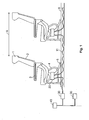
- FIG 4 illustrates a vehicle seat data system according to one embodiment.
- the vehicle seat 1 itself is identical to the seat 1 shown in Figure 1 .
- the seat distribution box 20, area distribution box 40 and floor distribution boxes 30 are identical to that shown in Figure 1 .
- the interconnect between the seat distribution box 20 and the floor distribution box 30 differs.
- a leaky cable 50 is provided within the seat rail 6.
- the leaky cable 50 is typically retained within a conduit of the seat rail 6. However, it will be appreciated that the leaky cable 50 may be provided outside or adjacent the seat rail 6, if that would be more convenient.
- the leaky cable 50 is a coaxial cable operable to carry RF signals.
- the leaky cable 50 will typically be provided with unshielded apertures along the cable length to enable the transmission of RF signals from and into the leaky cable 50. These apertures will typically be spaced at a distance which matches the step B of the seat rail 6.
- the leaky cable 50 is coupled at one end with floor distribution box 30, which transmits and receives RF signals used by the in-flight entertainment system and is terminated at the other end by a terminator 60 to reduce signal reflections.
- the transducer 70 is operable to couple wirelessly with the leaky cable 50 to enable RF signals to be transmitted between the transducer 70 and the leaky cable 50. The transducer 70 then provides these signals over a wiring harness 80 to the seat distribution box 20.
- the leaky cable 50, the transducer 70 and the cable harness 80 act as a direct replacement for the wiring harness 11.
- the arrangement illustrated in Figure 4 has significant advantages in that when the pitch A of the seats 1 is changed, this can be done without having to disconnect any cables from the seat distribution box 20.
- the arrangements can enable any pitch A to be selected without needing any specific cable length dedicated to that particular pitch. It will be appreciated that this significantly simplifies changing the pitch A of the seats since none of the cabling infrastructure needs to be disturbed. Also, by providing a leaky cable 50 with spaced unshielded portions, the amount of interference generated by the leaky cable 50 is minimised.
- embodiments enable the seat pitch A to be altered without the need to remove any cabling or to disconnect the interconnect each time.
- the seat 1 may be moved to a new position and the transceiver 70 may still wirelessly couple with the elongate medium 50.
- the elongate medium 50 can be retained in place without needing to be removed when the seat 1 is moved and the transceiver 70 located on the vehicle seat 1 will enable data signals to be transmitted with the elongate medium 50 even when the transceiver 70 is in its new location.
Abstract
Description
- The present invention relates to a vehicle seat data interconnect, a method and a vehicle seat data system.
- In a vehicle which has multiple seats such as, for example, an aircraft, a bus or a coach, the seats are typically provided in rows. Where an in-vehicle entertainment system is provided each row of seats typically needs to be coupled to that entertainment system. Each seat will typically have control devices for controlling the entertainment system, as well as audio devices for transmitting or receiving audio data. The visual display units are generally mounted in the back of each seat and so the user will operate the visual display unit mounted in the back of the seat in front of him.
- Hence, it is know to "daisy chain" a row of seats with the row of seats to its front and rear. A cable harness is provided with couples the rows of seats together. These cable harnesses typically attach to a seat distribution box provided for each row of seats, with the cables running in conduits under the floor between the rows of seats.
- To enable the distance between rows of seats (known as the "pitch") to be altered, seat rails are provided which are fixed to the floor of the vehicle and which receive the seat legs. The seats can be positioned in the desired location along the seat rails and then fixed in place. Once in place, the cable harness runs from the seat distribution box and into a cavity provided by the seat rail. The cable harness then exits the seat rail near the adjacent row and couples to its seat distribution box. The cavity is typically covered by an extrusion to protect the cable harness therein. Hence, rows of seats are coupled together to enable control of the entertainment system to be achieved and the cabling is neatly concealed within the seat rail.
- When it is desired to change the pitch of the seats it is necessary to remove the extrusion protecting the cable harness, to uncouple the cable harness from the seat distribution boxes and to withdraw the cable harness from at least the region of the seat rail into which a seat will be moved. Once the seat has been moved, the cable is reinserted into the seat rail up to the seat and reconnected to the seat distribution box. The cable harness is typically pulled to remove any slack and then connected to the next seat distribution box. In the event that the pitch of the seats is decreased, any excess cable harness must be somehow accommodated within the seat rail or, if this is not possible, a shorter cable harness used. Conversely, if the pitch of the seats is increased and the existing cable harness is too short, then a longer cable harness must be provided. In any event, each connection then needs to be retested since the mechanical connection between the seat distribution box and the cable harness has been broken and remade.
- An alternative arrangement provides so-called "spacers" which are rigid mechanical and electrical couplings of fixed length which couple with an interface provided within the legs of each seat. These spacers are retained in the inter-seat gap of the seat rail.
- It is desired to provide an improved interconnect.
- According to a first aspect of the present invention there is provided a vehicle seat data interconnect, comprising: an elongate medium operable to propagate data signals along its length; and a transceiver locatable with a vehicle seat and operable to wirelessly couple with the elongate medium to enable data signals to be transmitted between the transceiver and the elongate medium.
- The first aspect recognises that a problem with the approaches mentioned above is that the cable harness or spacer needs to be removed from the seat rail in the vehicle floor and disconnected from the seat distribution box each time a change in seat pitch is required. Removing the interconnect each time is extremely time-intensive and can result in a mechanical or electrical failure between the seat distribution box and the interconnect, leading to the non-functioning of the entertainment system. Also, another problem with the approaches mentioned above is that a large inventory of different length interconnects needs to be provided in order to accommodate all the different possible combinations of pitches that may be required. Hence, the flexibility of the seat layouts can be severely restricted due to the lack of availability of cables or spacers of the correct length.
- Accordingly, an elongate medium is provided which is operable to propagate signals along its length. This medium may be retained substantially along the entire length of the seat rail. A transceiver may be provided on a vehicle seat and which couples with the elongate medium to enable data signals to be wirelessly transmitted therebetween. It will be appreciated that this arrangement enables the seat pitch to be altered without the need to remove the cabling or to disconnect from the seat distribution box each time. Instead, the seat may be moved to a new position and the transceiver may still wirelessly couple with the elongate medium. Hence, the elongate medium can be retained within the seat rail without needing to be removed when the seat is moved and the transceiver located on the vehicle seat will enable data signals to be transmitted with the elongate medium even when the transceiver is in its new location.
- In embodiments, the transceiver is a radio frequency transceiver. Hence, radio frequency (RF) communication can be achieved between the medium and the transceiver through the transmission of RF signals therebetween to enable the wireless communication.
- In embodiments, the transceiver is operable to receive radio frequency data signals from the elongate medium. Hence, the transceiver may receive RF data signals which have been propagated along the elongate member.
- In embodiments, the transceiver is operable to transmit radio frequency data signals into the elongate medium. Hence, the transceiver may transmit RF signals into the elongate medium for propagation therein.
- In embodiments, the transceiver is operable to couple with a seat distribution box. Hence, the transceiver may be coupled with a seat distribution box which receives or transmits data signals.
- In embodiments, the elongate medium has unshielded areas through which the data signals are transmittable. Hence, portions or regions may be provided in the elongate medium which are unshielded, wireless communication can therefore be achieved between the elongate medium and the transceiver in the vicinity of these portions or regions. Providing shielding elsewhere helps to minimise any interference with other devices or cabling in the vicinity, which is a key concern in some safety critical environments.
- In embodiments, the unshielded areas are spaced along the elongate medium. Hence, the unshielded areas may be provided at particular predetermined spaced intervals along the elongate medium. This enables wireless communication to occur at any of a variety of different predetermined locations along the length the elongate medium and provides increased flexibility in the positioning of the seat.
- In embodiments, the unshielded areas are spaced along the elongate medium with a spacing which matches a pitch spacing of the vehicle seat. By matching the location of the unshielded areas to coincide with the pitch spacing provided in a seat rail supporting the seat, the correct alignment of the transceiver with the unshielded area may be achieved for any pitch set for the seats on that seat rail.
- In embodiments, the elongate medium is a leaky cable. Providing a leaky cable, such as a coaxial cable having portions omitted from the cable shielding, conveniently enables local and limited wireless communication to be achieved between the cable and the transceiver.
- In embodiments, the elongate medium couples with a distribution box. Hence, the transceiver may be coupled with an area or a floor distribution box which receives and/or transmits data signals such as control and audio-visual multiplexes associated with an entertainment system.
- According to a second aspect of the present invention, there is provided a method, comprising the steps of: propagating data signals along an elongate medium; and wirelessly coupling a transceiver locatable with a vehicle seat with the elongate medium; and transmitting data signals between the transceiver and the elongate medium.
- In embodiments, there are provided method steps and features corresponding to features of the first aspect.
- According to a third aspect of the present invention, there is provided a vehicle seat data system, comprising: a distribution box; an elongate medium coupled with the distribution box to enable data signals to be transmitted between the distribution box and the elongate medium, the elongate medium being operable to propagate data signals along its length; a transceiver located with a vehicle seat and operable to wirelessly couple with the elongate medium to enable data signals to be transmitted between the transceiver and the elongate medium; and a seat distribution box coupled with the transceiver to enable data signals to be transmitted between the seat distribution box and the elongate medium.
- In embodiments, there are provided features corresponding to features of the first aspect.
- Embodiments of the present invention will now be described with reference to the accompanying drawings in which:
-
Figure 1 is a side elevation of an existing arrangement showing seats on a seat rail; -
Figure 2 is a cross section of the seat rail and supporting structure; -
Figure 3 is a plan view of a portion of the seat rail; and -
Figure 4 is a side elevation schematically illustrating the vehicle seat interconnect and system according to one embodiment. -
Figure 1 is a side elevation of an existing arrangement showing seats 1 on aseat rail 6. Theseat rail 6 is mounted with the floor of the vehicle. Thelegs 4 of the seat 1 are mounted in theseat rail 6 and fixed in position usingseat fixings 5. Theseat fixings 5 engage inrecesses 7 of the seat rail 6 (shown in more detail inFigure 3 ) to lock the seat 1 in position. The pitch A is the distance between the seats 1 and may be varied to suit different configuration needs of the vehicle housing the seats 1. - The armrest of the seat 1 will typically house
control devices 3 for interaction with a vehicle information system such as, for example, afloor distribution box 30 and anarea distribution box 40 of an in-flight entertainment system. Thecontrol devices 3 will typically operate avisual display unit 2 mounted in the seat ahead. Hence, signals will need to pass between seats. To achieve this each seat or row of seats is provided with aseat distribution box 20 which is coupled with thecontrol devices 3 and thevisual display unit 2. Theseat distribution box 20 will also be coupled with adjacent seat distribution boxes via acable harness 11. Thecable harness 11 runs in a conduit provided in theseat rail 6. Thecable harness 11 is protected by a track cover (not shown) which is mounted over theseat rail 6 for safety reasons. Thecable harness 11 is coupled with thefloor distribution box 30, which in turn is coupled with thearea distribution box 40. Thearea distribution box 40 andfloor distribution boxes 30 enable the entertainment system to be controlled and distributed throughout the vehicle. -
Figure 2 shows a cross-section of the vehicle floor which includes theseat rail 6. As can be seen, thewiring harness 11 is retained within theseat rail 6 in at least the regions between seats 1. -
Figure 3 shows in more detail a plan view of theseat rail 6. In particular, theseat rail 6 is provided with a number ofrecesses 7 for receiving theseat mountings 5. Typically, the spacing between these recesses 7 (known as the step) is fixed. A typical step B is 1" (25.4mm). -
Figure 4 illustrates a vehicle seat data system according to one embodiment. The vehicle seat 1 itself is identical to the seat 1 shown inFigure 1 . Also, theseat distribution box 20,area distribution box 40 andfloor distribution boxes 30 are identical to that shown inFigure 1 . However, the interconnect between theseat distribution box 20 and thefloor distribution box 30 differs. - A
leaky cable 50 is provided within theseat rail 6. Theleaky cable 50 is typically retained within a conduit of theseat rail 6. However, it will be appreciated that theleaky cable 50 may be provided outside or adjacent theseat rail 6, if that would be more convenient. Theleaky cable 50 is a coaxial cable operable to carry RF signals. Theleaky cable 50 will typically be provided with unshielded apertures along the cable length to enable the transmission of RF signals from and into theleaky cable 50. These apertures will typically be spaced at a distance which matches the step B of theseat rail 6. Theleaky cable 50 is coupled at one end withfloor distribution box 30, which transmits and receives RF signals used by the in-flight entertainment system and is terminated at the other end by aterminator 60 to reduce signal reflections. - Attached to the seat 1 is a
transducer 70. Thetransducer 70 is operable to couple wirelessly with theleaky cable 50 to enable RF signals to be transmitted between thetransducer 70 and theleaky cable 50. Thetransducer 70 then provides these signals over awiring harness 80 to theseat distribution box 20. - Hence, it can be seen that the
leaky cable 50, thetransducer 70 and thecable harness 80 act as a direct replacement for thewiring harness 11. Furthermore, the arrangement illustrated inFigure 4 has significant advantages in that when the pitch A of the seats 1 is changed, this can be done without having to disconnect any cables from theseat distribution box 20. Furthermore, the arrangements can enable any pitch A to be selected without needing any specific cable length dedicated to that particular pitch. It will be appreciated that this significantly simplifies changing the pitch A of the seats since none of the cabling infrastructure needs to be disturbed. Also, by providing aleaky cable 50 with spaced unshielded portions, the amount of interference generated by theleaky cable 50 is minimised. Furthermore, by matching the spacing of the unshielded portions to the step of theseat rail 6 the mechanical alignment of thetransducer 70 with theleaky cable 50 can be assured. Accordingly, the need to comprehensively test the in-flight entertainment system following a change in pitch A can be obviated. Also, in the event that oneseat distribution box 20 develops a fault, normal operation of other rows of seats can be maintained whereas in the arrangement shown inFigure 1 , a faultyseat distribution box 20 can often cause a failure for some or all devices connected to the associatedfloor distribution box 30. - Hence, embodiments enable the seat pitch A to be altered without the need to remove any cabling or to disconnect the interconnect each time. Instead, the seat 1 may be moved to a new position and the
transceiver 70 may still wirelessly couple with theelongate medium 50. The elongate medium 50 can be retained in place without needing to be removed when the seat 1 is moved and thetransceiver 70 located on the vehicle seat 1 will enable data signals to be transmitted with the elongate medium 50 even when thetransceiver 70 is in its new location. - Although a particular embodiment has been described herein it will be apparent that that invention is not limited thereto, and that many modifications and additions may be made within the scope of the invention. For example, various combinations of the features from the following dependent claims could be made with features of the independent claims without departing from the scope of the present invention.
Claims (22)
- A vehicle seat data interconnect, comprising:an elongate medium operable to propagate data signals along its length; anda transceiver located with a vehicle seat and operable to wirelessly couple with said elongate medium to enable data signals to be transmitted between said transceiver and said elongate medium.
- The vehicle seat data interconnect of claim 1, wherein said transceiver is a radio frequency transceiver.
- The vehicle seat data interconnect of claim 2, wherein said transceiver is operable to receive radio frequency data signals from said elongate medium.
- The vehicle seat data interconnect of claim 2 or claim 3, wherein said transceiver is operable to transmit radio frequency data signals into said elongate medium.
- The vehicle seat data interconnect of any preceding claim, wherein said transceiver is operable to couple with a seat distribution box.
- The vehicle seat data interconnect of any preceding claim, wherein said elongate medium has unshielded areas through which said data signals are transmittable.
- The vehicle seat data interconnect of claim 6, wherein said unshielded areas are spaced along said elongate medium.
- The vehicle seat data interconnect of claim 7, wherein said unshielded areas are spaced along said elongate medium with a spacing which matches a pitch spacing of said vehicle seat.
- The vehicle seat data interconnect of any preceding claim, wherein said elongate medium is a leaky cable.
- The vehicle seat data interconnect of any preceding claim, wherein said elongate medium couples with a distribution box.
- A method, comprising the steps of:propagating data signals along an elongate medium; andwirelessly coupling a transceiver locatable with a vehicle seat with said elongate medium; andtransmitting data signals between said transceiver and said elongate medium.
- The method of claim 11, wherein said transceiver is a radio frequency transceiver.
- The method of claim 12, wherein said step of transmitting comprises receiving radio frequency data signals from said elongate medium.
- The method of claim 12 or claim 13, wherein said step of transmitting comprises transmitting radio frequency data signals into said elongate medium.
- The method of any one of claims 11 to 14, comprising the step of:coupling said transceiver with a seat distribution box.
- The method of any one of claims 11 to 15, wherein said elongate medium has unshielded areas which through which said data signals are transmittable.
- The method of claim 16, wherein said unshielded areas are spaced along said elongate medium.
- The method of claim 17, wherein said unshielded areas are spaced along said elongate medium with a spacing which matches a pitch spacing of said vehicle seat.
- The method of any one of claims 11 to 18, wherein said elongate medium is a leaky cable.
- The method of any one of claims 11 to 19, comprising the step of:coupling said elongate medium with a distribution box.
- A vehicle seat data system, comprising:a distribution box;an elongate medium coupled with said distribution box to enable data signals to be transmitted between said distribution box and said elongate medium, said elongate medium being operable to propagate data signals along its length;a transceiver locatable with a vehicle seat and operable to wirelessly couple with said elongate medium to enable data signals to be transmitted between said transceiver and said elongate medium; anda seat distribution box coupled with said transceiver to enable data signals to be transmitted between said seat distribution box and said elongate medium.
- The vehicle seat data system of claim 21, comprising:a vehicle seat rail arranged to receive said vehicle seat and within which said elongate medium is provided.
Applications Claiming Priority (1)
| Application Number | Priority Date | Filing Date | Title |
|---|---|---|---|
| GB0712574A GB2450526A (en) | 2007-06-28 | 2007-06-28 | Vehicle seat interconnect, method and vehicle seat data system |
Publications (4)
| Publication Number | Publication Date |
|---|---|
| EP2008862A2 true EP2008862A2 (en) | 2008-12-31 |
| EP2008862A8 EP2008862A8 (en) | 2009-03-18 |
| EP2008862A3 EP2008862A3 (en) | 2010-11-03 |
| EP2008862B1 EP2008862B1 (en) | 2014-04-23 |
Family
ID=38420885
Family Applications (1)
| Application Number | Title | Priority Date | Filing Date |
|---|---|---|---|
| EP08252125.3A Active EP2008862B1 (en) | 2007-06-28 | 2008-06-19 | Vehicle seat interconnect, method and vehicle seat data system |
Country Status (3)
| Country | Link |
|---|---|
| US (1) | US8677422B2 (en) |
| EP (1) | EP2008862B1 (en) |
| GB (1) | GB2450526A (en) |
Families Citing this family (2)
| Publication number | Priority date | Publication date | Assignee | Title |
|---|---|---|---|---|
| GB2575107A (en) * | 2018-06-29 | 2020-01-01 | Airbus Operations Ltd | Aircraft cable routing system and method of installation thereof |
| US11027680B2 (en) * | 2018-12-13 | 2021-06-08 | Ford Global Technologies, Llc | Vehicle tracks |
Citations (2)
| Publication number | Priority date | Publication date | Assignee | Title |
|---|---|---|---|---|
| EP0279608A2 (en) | 1987-02-17 | 1988-08-24 | Sony Corporation | Two way communication systems |
| US20060234700A1 (en) | 2004-12-28 | 2006-10-19 | Livetv, Llc | Aircraft in-flight entertainment system including digital radio service and associated methods |
Family Cites Families (9)
| Publication number | Priority date | Publication date | Assignee | Title |
|---|---|---|---|---|
| US4428078A (en) | 1979-03-26 | 1984-01-24 | The Boeing Company | Wireless audio passenger entertainment system (WAPES) |
| US4736452A (en) * | 1986-09-17 | 1988-04-05 | The Boeing Company | Core coupled transmitter/receiver loops for connectorless entertainment systems |
| JP2658030B2 (en) * | 1987-01-30 | 1997-09-30 | ソニー株式会社 | Information transmission equipment |
| JP2722450B2 (en) * | 1987-02-25 | 1998-03-04 | ソニー株式会社 | Central control device |
| US4853555A (en) * | 1988-04-21 | 1989-08-01 | The Boeing Company | Electrical power transfer system for aircraft passenger entertainment system |
| US5230085A (en) | 1991-04-05 | 1993-07-20 | E-Systems, Inc. | Method and apparatus for wireless electromagnetic communication within a contained electromagnetic field |
| JP3370260B2 (en) * | 1997-08-29 | 2003-01-27 | 八洲電研株式会社 | High frequency signal line |
| US7769398B2 (en) | 2002-11-15 | 2010-08-03 | The Boeing Company | Broadband wireless distribution system for mobile platform interior |
| US20060271970A1 (en) * | 2005-05-17 | 2006-11-30 | Mitchell Bradley J | Apparatus and method for transmitting information between seats in a mobile platform using an existing power line |
-
2007
- 2007-06-28 GB GB0712574A patent/GB2450526A/en not_active Withdrawn
-
2008
- 2008-06-18 US US12/141,372 patent/US8677422B2/en active Active
- 2008-06-19 EP EP08252125.3A patent/EP2008862B1/en active Active
Patent Citations (2)
| Publication number | Priority date | Publication date | Assignee | Title |
|---|---|---|---|---|
| EP0279608A2 (en) | 1987-02-17 | 1988-08-24 | Sony Corporation | Two way communication systems |
| US20060234700A1 (en) | 2004-12-28 | 2006-10-19 | Livetv, Llc | Aircraft in-flight entertainment system including digital radio service and associated methods |
Also Published As
| Publication number | Publication date |
|---|---|
| GB2450526A (en) | 2008-12-31 |
| US20090007191A1 (en) | 2009-01-01 |
| US8677422B2 (en) | 2014-03-18 |
| EP2008862A8 (en) | 2009-03-18 |
| EP2008862A3 (en) | 2010-11-03 |
| GB0712574D0 (en) | 2007-08-08 |
| EP2008862B1 (en) | 2014-04-23 |
Similar Documents
| Publication | Publication Date | Title |
|---|---|---|
| US6038426A (en) | System and method for securing a removable seat electronics unit without detachment of the communication cable | |
| US6503098B2 (en) | Wire harness structure | |
| EP1998502B1 (en) | Control channel for vehicle systems using the vehicle's power distribution system | |
| JP6483579B2 (en) | Data bus in a box (BIB) system design and implementation | |
| GB2417369A (en) | Seat electrical connectors integrated into floor | |
| US20060271970A1 (en) | Apparatus and method for transmitting information between seats in a mobile platform using an existing power line | |
| CA2462405A1 (en) | Under floor remote seat cluster and integrated housing system for aircraft passenger entertainment systems and the like | |
| KR102206497B1 (en) | Modular system for distributing electrical power and data between structures | |
| WO2010079618A1 (en) | Train information transmitting and receiving system | |
| AU2005228208B2 (en) | Adjustable length cabling systems | |
| CN101218727A (en) | Flexible power raceway | |
| EP2008862B1 (en) | Vehicle seat interconnect, method and vehicle seat data system | |
| US6843681B2 (en) | Replacement cover having integrated data ports for power port assembly on commercial aircraft | |
| EP1404063A2 (en) | Communication circuit for a vehicle | |
| CN103718471A (en) | Data transmission device, railway vehicle junction unit and rail vehicle combination | |
| US10553993B2 (en) | Avionics system interface electrical connector | |
| US10525990B2 (en) | Wiring system, in particular for the connection between carriages of a railway vehicle | |
| CN108238065B (en) | Computer platform based on rail transit | |
| US20140138116A1 (en) | Adjustable Length Cabling Systems | |
| EP2170645A2 (en) | Vehicle seat interconnect | |
| JP4744487B2 (en) | Train information transmission / reception system | |
| US4503532A (en) | Multipoint fiber optic junction terminal | |
| KR101766237B1 (en) | Serial communication transformation device for localcentralized traffic control computer | |
| US20230391581A1 (en) | Electrical equipment mounting base plate with cable storage recess | |
| CN115871932A (en) | Contactless data communication and power supply device, in particular for an aircraft |
Legal Events
| Date | Code | Title | Description |
|---|---|---|---|
| PUAI | Public reference made under article 153(3) epc to a published international application that has entered the european phase |
Free format text: ORIGINAL CODE: 0009012 |
|
| AK | Designated contracting states |
Kind code of ref document: A2 Designated state(s): AT BE BG CH CY CZ DE DK EE ES FI FR GB GR HR HU IE IS IT LI LT LU LV MC MT NL NO PL PT RO SE SI SK TR |
|
| AX | Request for extension of the european patent |
Extension state: AL BA MK RS |
|
| RAP1 | Party data changed (applicant data changed or rights of an application transferred) |
Owner name: TYCO ELECTRONICS UK LTD. |
|
| PUAL | Search report despatched |
Free format text: ORIGINAL CODE: 0009013 |
|
| AK | Designated contracting states |
Kind code of ref document: A3 Designated state(s): AT BE BG CH CY CZ DE DK EE ES FI FR GB GR HR HU IE IS IT LI LT LU LV MC MT NL NO PL PT RO SE SI SK TR |
|
| AX | Request for extension of the european patent |
Extension state: AL BA MK RS |
|
| 17P | Request for examination filed |
Effective date: 20110427 |
|
| AKX | Designation fees paid |
Designated state(s): AT BE BG CH CY CZ DE DK EE ES FI FR GB GR HR HU IE IS IT LI LT LU LV MC MT NL NO PL PT RO SE SI SK TR |
|
| 17Q | First examination report despatched |
Effective date: 20111025 |
|
| GRAP | Despatch of communication of intention to grant a patent |
Free format text: ORIGINAL CODE: EPIDOSNIGR1 |
|
| INTG | Intention to grant announced |
Effective date: 20131114 |
|
| GRAS | Grant fee paid |
Free format text: ORIGINAL CODE: EPIDOSNIGR3 |
|
| GRAA | (expected) grant |
Free format text: ORIGINAL CODE: 0009210 |
|
| RIN1 | Information on inventor provided before grant (corrected) |
Inventor name: FURIO MIGUEL ANGEL Inventor name: KOPPE CHRISTIAN Inventor name: KAINTHAJE RAMACHANDRA, SHIVAPRAKASH Inventor name: HEGDE KUNDAPUR, NIRANJAN |
|
| AK | Designated contracting states |
Kind code of ref document: B1 Designated state(s): AT BE BG CH CY CZ DE DK EE ES FI FR GB GR HR HU IE IS IT LI LT LU LV MC MT NL NO PL PT RO SE SI SK TR |
|
| REG | Reference to a national code |
Ref country code: GB Ref legal event code: FG4D |
|
| REG | Reference to a national code |
Ref country code: CH Ref legal event code: EP |
|
| REG | Reference to a national code |
Ref country code: AT Ref legal event code: REF Ref document number: 663611 Country of ref document: AT Kind code of ref document: T Effective date: 20140515 |
|
| REG | Reference to a national code |
Ref country code: IE Ref legal event code: FG4D |
|
| REG | Reference to a national code |
Ref country code: DE Ref legal event code: R096 Ref document number: 602008031678 Country of ref document: DE Effective date: 20140612 |
|
| REG | Reference to a national code |
Ref country code: AT Ref legal event code: MK05 Ref document number: 663611 Country of ref document: AT Kind code of ref document: T Effective date: 20140423 |
|
| REG | Reference to a national code |
Ref country code: NL Ref legal event code: VDEP Effective date: 20140423 |
|
| REG | Reference to a national code |
Ref country code: LT Ref legal event code: MG4D |
|
| PG25 | Lapsed in a contracting state [announced via postgrant information from national office to epo] |
Ref country code: GR Free format text: LAPSE BECAUSE OF FAILURE TO SUBMIT A TRANSLATION OF THE DESCRIPTION OR TO PAY THE FEE WITHIN THE PRESCRIBED TIME-LIMIT Effective date: 20140724 Ref country code: FI Free format text: LAPSE BECAUSE OF FAILURE TO SUBMIT A TRANSLATION OF THE DESCRIPTION OR TO PAY THE FEE WITHIN THE PRESCRIBED TIME-LIMIT Effective date: 20140423 Ref country code: NO Free format text: LAPSE BECAUSE OF FAILURE TO SUBMIT A TRANSLATION OF THE DESCRIPTION OR TO PAY THE FEE WITHIN THE PRESCRIBED TIME-LIMIT Effective date: 20140723 Ref country code: NL Free format text: LAPSE BECAUSE OF FAILURE TO SUBMIT A TRANSLATION OF THE DESCRIPTION OR TO PAY THE FEE WITHIN THE PRESCRIBED TIME-LIMIT Effective date: 20140423 Ref country code: LT Free format text: LAPSE BECAUSE OF FAILURE TO SUBMIT A TRANSLATION OF THE DESCRIPTION OR TO PAY THE FEE WITHIN THE PRESCRIBED TIME-LIMIT Effective date: 20140423 Ref country code: CY Free format text: LAPSE BECAUSE OF FAILURE TO SUBMIT A TRANSLATION OF THE DESCRIPTION OR TO PAY THE FEE WITHIN THE PRESCRIBED TIME-LIMIT Effective date: 20140423 Ref country code: BG Free format text: LAPSE BECAUSE OF FAILURE TO SUBMIT A TRANSLATION OF THE DESCRIPTION OR TO PAY THE FEE WITHIN THE PRESCRIBED TIME-LIMIT Effective date: 20140723 Ref country code: IS Free format text: LAPSE BECAUSE OF FAILURE TO SUBMIT A TRANSLATION OF THE DESCRIPTION OR TO PAY THE FEE WITHIN THE PRESCRIBED TIME-LIMIT Effective date: 20140823 |
|
| PG25 | Lapsed in a contracting state [announced via postgrant information from national office to epo] |
Ref country code: LV Free format text: LAPSE BECAUSE OF FAILURE TO SUBMIT A TRANSLATION OF THE DESCRIPTION OR TO PAY THE FEE WITHIN THE PRESCRIBED TIME-LIMIT Effective date: 20140423 Ref country code: AT Free format text: LAPSE BECAUSE OF FAILURE TO SUBMIT A TRANSLATION OF THE DESCRIPTION OR TO PAY THE FEE WITHIN THE PRESCRIBED TIME-LIMIT Effective date: 20140423 Ref country code: ES Free format text: LAPSE BECAUSE OF FAILURE TO SUBMIT A TRANSLATION OF THE DESCRIPTION OR TO PAY THE FEE WITHIN THE PRESCRIBED TIME-LIMIT Effective date: 20140423 Ref country code: HR Free format text: LAPSE BECAUSE OF FAILURE TO SUBMIT A TRANSLATION OF THE DESCRIPTION OR TO PAY THE FEE WITHIN THE PRESCRIBED TIME-LIMIT Effective date: 20140423 Ref country code: SE Free format text: LAPSE BECAUSE OF FAILURE TO SUBMIT A TRANSLATION OF THE DESCRIPTION OR TO PAY THE FEE WITHIN THE PRESCRIBED TIME-LIMIT Effective date: 20140423 Ref country code: PL Free format text: LAPSE BECAUSE OF FAILURE TO SUBMIT A TRANSLATION OF THE DESCRIPTION OR TO PAY THE FEE WITHIN THE PRESCRIBED TIME-LIMIT Effective date: 20140423 |
|
| PG25 | Lapsed in a contracting state [announced via postgrant information from national office to epo] |
Ref country code: PT Free format text: LAPSE BECAUSE OF FAILURE TO SUBMIT A TRANSLATION OF THE DESCRIPTION OR TO PAY THE FEE WITHIN THE PRESCRIBED TIME-LIMIT Effective date: 20140825 |
|
| REG | Reference to a national code |
Ref country code: DE Ref legal event code: R097 Ref document number: 602008031678 Country of ref document: DE |
|
| PG25 | Lapsed in a contracting state [announced via postgrant information from national office to epo] |
Ref country code: CZ Free format text: LAPSE BECAUSE OF FAILURE TO SUBMIT A TRANSLATION OF THE DESCRIPTION OR TO PAY THE FEE WITHIN THE PRESCRIBED TIME-LIMIT Effective date: 20140423 Ref country code: BE Free format text: LAPSE BECAUSE OF FAILURE TO SUBMIT A TRANSLATION OF THE DESCRIPTION OR TO PAY THE FEE WITHIN THE PRESCRIBED TIME-LIMIT Effective date: 20140423 Ref country code: MC Free format text: LAPSE BECAUSE OF FAILURE TO SUBMIT A TRANSLATION OF THE DESCRIPTION OR TO PAY THE FEE WITHIN THE PRESCRIBED TIME-LIMIT Effective date: 20140423 Ref country code: LU Free format text: LAPSE BECAUSE OF FAILURE TO SUBMIT A TRANSLATION OF THE DESCRIPTION OR TO PAY THE FEE WITHIN THE PRESCRIBED TIME-LIMIT Effective date: 20140619 Ref country code: DK Free format text: LAPSE BECAUSE OF FAILURE TO SUBMIT A TRANSLATION OF THE DESCRIPTION OR TO PAY THE FEE WITHIN THE PRESCRIBED TIME-LIMIT Effective date: 20140423 Ref country code: SK Free format text: LAPSE BECAUSE OF FAILURE TO SUBMIT A TRANSLATION OF THE DESCRIPTION OR TO PAY THE FEE WITHIN THE PRESCRIBED TIME-LIMIT Effective date: 20140423 Ref country code: EE Free format text: LAPSE BECAUSE OF FAILURE TO SUBMIT A TRANSLATION OF THE DESCRIPTION OR TO PAY THE FEE WITHIN THE PRESCRIBED TIME-LIMIT Effective date: 20140423 Ref country code: RO Free format text: LAPSE BECAUSE OF FAILURE TO SUBMIT A TRANSLATION OF THE DESCRIPTION OR TO PAY THE FEE WITHIN THE PRESCRIBED TIME-LIMIT Effective date: 20140423 |
|
| REG | Reference to a national code |
Ref country code: CH Ref legal event code: PL |
|
| PLBE | No opposition filed within time limit |
Free format text: ORIGINAL CODE: 0009261 |
|
| STAA | Information on the status of an ep patent application or granted ep patent |
Free format text: STATUS: NO OPPOSITION FILED WITHIN TIME LIMIT |
|
| REG | Reference to a national code |
Ref country code: IE Ref legal event code: MM4A |
|
| PG25 | Lapsed in a contracting state [announced via postgrant information from national office to epo] |
Ref country code: IT Free format text: LAPSE BECAUSE OF FAILURE TO SUBMIT A TRANSLATION OF THE DESCRIPTION OR TO PAY THE FEE WITHIN THE PRESCRIBED TIME-LIMIT Effective date: 20140423 |
|
| 26N | No opposition filed |
Effective date: 20150126 |
|
| PG25 | Lapsed in a contracting state [announced via postgrant information from national office to epo] |
Ref country code: CH Free format text: LAPSE BECAUSE OF NON-PAYMENT OF DUE FEES Effective date: 20140630 Ref country code: LI Free format text: LAPSE BECAUSE OF NON-PAYMENT OF DUE FEES Effective date: 20140630 Ref country code: IE Free format text: LAPSE BECAUSE OF NON-PAYMENT OF DUE FEES Effective date: 20140619 |
|
| REG | Reference to a national code |
Ref country code: DE Ref legal event code: R097 Ref document number: 602008031678 Country of ref document: DE Effective date: 20150126 |
|
| PG25 | Lapsed in a contracting state [announced via postgrant information from national office to epo] |
Ref country code: SI Free format text: LAPSE BECAUSE OF FAILURE TO SUBMIT A TRANSLATION OF THE DESCRIPTION OR TO PAY THE FEE WITHIN THE PRESCRIBED TIME-LIMIT Effective date: 20140423 |
|
| PG25 | Lapsed in a contracting state [announced via postgrant information from national office to epo] |
Ref country code: MT Free format text: LAPSE BECAUSE OF FAILURE TO SUBMIT A TRANSLATION OF THE DESCRIPTION OR TO PAY THE FEE WITHIN THE PRESCRIBED TIME-LIMIT Effective date: 20140423 |
|
| REG | Reference to a national code |
Ref country code: FR Ref legal event code: PLFP Year of fee payment: 9 |
|
| PG25 | Lapsed in a contracting state [announced via postgrant information from national office to epo] |
Ref country code: TR Free format text: LAPSE BECAUSE OF FAILURE TO SUBMIT A TRANSLATION OF THE DESCRIPTION OR TO PAY THE FEE WITHIN THE PRESCRIBED TIME-LIMIT Effective date: 20140423 Ref country code: HU Free format text: LAPSE BECAUSE OF FAILURE TO SUBMIT A TRANSLATION OF THE DESCRIPTION OR TO PAY THE FEE WITHIN THE PRESCRIBED TIME-LIMIT; INVALID AB INITIO Effective date: 20080619 |
|
| REG | Reference to a national code |
Ref country code: FR Ref legal event code: PLFP Year of fee payment: 10 |
|
| REG | Reference to a national code |
Ref country code: FR Ref legal event code: PLFP Year of fee payment: 11 |
|
| REG | Reference to a national code |
Ref country code: FR Ref legal event code: PLFP Year of fee payment: 16 |
|
| PGFP | Annual fee paid to national office [announced via postgrant information from national office to epo] |
Ref country code: FR Payment date: 20230411 Year of fee payment: 16 Ref country code: DE Payment date: 20230425 Year of fee payment: 16 |
|
| PGFP | Annual fee paid to national office [announced via postgrant information from national office to epo] |
Ref country code: GB Payment date: 20230427 Year of fee payment: 16 |