EP2012147A2 - Triple reflector and wide angle sensor system comprising the same - Google Patents
Triple reflector and wide angle sensor system comprising the same Download PDFInfo
- Publication number
- EP2012147A2 EP2012147A2 EP08164497A EP08164497A EP2012147A2 EP 2012147 A2 EP2012147 A2 EP 2012147A2 EP 08164497 A EP08164497 A EP 08164497A EP 08164497 A EP08164497 A EP 08164497A EP 2012147 A2 EP2012147 A2 EP 2012147A2
- Authority
- EP
- European Patent Office
- Prior art keywords
- triple
- reflector
- light
- angle
- wide
- Prior art date
- Legal status (The legal status is an assumption and is not a legal conclusion. Google has not performed a legal analysis and makes no representation as to the accuracy of the status listed.)
- Withdrawn
Links
Images


Classifications
-
- B—PERFORMING OPERATIONS; TRANSPORTING
- B29—WORKING OF PLASTICS; WORKING OF SUBSTANCES IN A PLASTIC STATE IN GENERAL
- B29D—PRODUCING PARTICULAR ARTICLES FROM PLASTICS OR FROM SUBSTANCES IN A PLASTIC STATE
- B29D11/00—Producing optical elements, e.g. lenses or prisms
- B29D11/00605—Production of reflex reflectors
-
- G—PHYSICS
- G02—OPTICS
- G02B—OPTICAL ELEMENTS, SYSTEMS OR APPARATUS
- G02B5/00—Optical elements other than lenses
- G02B5/12—Reflex reflectors
- G02B5/122—Reflex reflectors cube corner, trihedral or triple reflector type
-
- G—PHYSICS
- G02—OPTICS
- G02B—OPTICAL ELEMENTS, SYSTEMS OR APPARATUS
- G02B5/00—Optical elements other than lenses
- G02B5/12—Reflex reflectors
- G02B5/122—Reflex reflectors cube corner, trihedral or triple reflector type
- G02B5/124—Reflex reflectors cube corner, trihedral or triple reflector type plural reflecting elements forming part of a unitary plate or sheet
Definitions
- the invention relates to a method and the formation of a suitable reflector for wide-angle observation of a reflective surface by means of a reflex sensor, which may also be equipped with polarizing filters or work as a laser reflection sensor.
- the triple-angle wide-angle sensor system consists of a doctrine for selecting the viewing angle and a triple reflector consisting of a plurality of triplets.
- the triple partial areas arranged around the triple center are mirror sides, almost at right angles to each other, and the axis of the triple alternates by -5 ° and + 5 ° or more from the incidence slot of the reflector surface.
- a special feature of the triples is the considerable extension of at least one triple surface.
- the aim of the triple-angle wide-angle sensor system is to provide a reflex sensor system capable of observing an area having an opening angle of 80 ° and more at a retroreflective value at each illuminance angle of the observed horizontal area of at least 3,000 mcd / lx.
- moving bodies in space for example vehicles or transport gondolas, can be observed, even if these bodies change their angle to the observer, for example when a conveyor nacelle is guided in a curve.
- the problem is that so far there are no high-quality reflex surfaces on the market for the tasks of the reflex sensor, which provide an intense Retroflexsignal resistant, especially not if the reflective surface is positioned at 40 ° and more deviating from the Lot.
- the reflectors or reflective films on the market as far as they have wide-angle properties, are designed for road traffic, for reflective signs or personal protection reflectors on clothes. These reflective structures produce a broadband distribution of the reflected light. As a result, their reflected light energy is insufficient to give reflex sensors bundled reliable retroflex signals. For reflex sensors, as much of the light as possible has to be retroflected in a targeted manner to the receiver.
- this novel triple reflector can also with well-known Technology can be formed as Mikrocubereflektor, as he is particularly required for the laser sensor or film technology.
- the requirements for laser sensors are the inventor in the DE 197 27 527 described.
- pyramidal triple surfaces are completely unsuitable, on the one hand, because they retroflect only about 66 ° of the light, on the other hand, because they are unsuitable for the required light beam contour and precision for laser sensors.
- the invention therefore uses a special design of fullcube triples.
- triple forms such as the three-sided pyramid.
- preference must be given to the modification of the fullcube because, in principle, it has a much lower scattering loss than the pyramid.
- Pyramidal triple structures can be cut out of a flat common area, whereas fullcube triplets in toolmaking require the arrangement of a large number of components in order to represent large structured areas made up of a large number of triplets.
- the production methods and their advantages and disadvantages in the production of triples are known in the art and need not be repeated here.
- the invention takes advantage of the experience gained with the manufacture and use of Fullcube triples in the art.
- the Fullcube triplet has the excellent property of receiving incident light over a wide tolerance range of the angle of incidence and retroflecting it almost completely to the light source.
- the retroflexion takes place via the light reflection on the three square surfaces of the fullcube triple.
- This angle tolerance for the incident light is used in practical application today in most retro-reflective sensors.
- the mounting and alignment of the reflectors in relation to the transmitter / receiver system is simple and fault-tolerant. Also Beam movements due to vibrations are usually tolerated by this reflection element with fullcube triples.
- triple systems that can be assigned to the fullcube. Because it is essential to distinguish between triples, which are pyramidal triples that can be cut from a base area, and fullcube triples, which can only be produced by joining subsegments.
- the production of the retroreflective technology knows Fullcube triple, whose triple axis is deviating from the incidence of the reflector surface aligned.
- the wide angle sensor system uses as a triple reflector a particular variation of the full cube triple, in which at least one triple partial area is substantially larger than the smallest triple partial area.
- This enlarged, extended triple part surface helps to catch even very wide-angle incident light and pass it on to the other triple partial areas, so that the light is retroflected in the direction of the light source.
- the result is a triple, which works completely surprisingly in practice substantially marwinkliger, as one could expect.
- each triple at least a triple partial area is much larger than the smallest Tripelteil constitutional the triple. It is only the substantially enlarged, namely prolonged triple partial area, which makes it possible to capture incident light at very wide angles and to achieve the excellent reflection values shown in FIG. 34 and the table of FIG. 35.
- the particular triple mold according to the invention with enlarged, extended triple part surface can be achieved when the triples in the plate method, which in the British Patent 269,760 to Stimson is described. Deviating from this, of course, the modern production techniques and materials of microstructure technology are used. But at one point, the inventive structure of the reflector deviates significantly from Stimson. Is there the triple aligned aligned to the incidence slot, the triple axes of the triple are strongly different from the incidence of the reflector surface aligned, namely at least +/- 5 ° and more and combined with triples whose triple axes, for example, +/- 15 ° from Deviating solder deviate the reflector surface.
- the desired extended triple part surface arises when notching the tool element plates when using the Stimson plate method by the oblique wedge-shaped cutting in the plates ( FIGS. 11 and 12 ).
- the invention proposes a wide-angle sensor with a reflector in which a light receiver is used to a light transmitter so that the observation angle is as small as possible.
- the viewing angle of 0 ° means that the light receiver is positioned towards the light emitter so that the light retroreflected by the reflector is received on the same axis as it was transmitted.
- Such arrangements are known in the sensor art and are solved, for example, by using semi-transparent mirrors or beam splitters. However, some light energy is lost in this arrangement, because even unwanted beam paths arise. To avoid such complex optical devices, it is sufficient for the invention Sensor system to position the light receiver as close to the axis of the light emitter, so that an observation angle greater than 0 °, for example, 0.2 °, and not more than 1 ° is formed.
- the reflector can be observed over a horizontal of about + 40 ° to -40 °, which corresponds to an opening angle of the surface observed by the sensor of about 80 ° and a constant retroreflectance of the reflector of over 3,000 mcd / lx.
- the opening angle can be significantly extended. Because with the tilting of the triple axis away from the incidence slot of the reflector surface, ie with the enlargement of the triple axis, also increases the extended triple part surface, which captures the light much better.
- the amazing effect of the system according to the invention is based on this particular triple shape of the reflector, which achieves the Weitwinkltechnik the reflector not only by pivoting the triple axis, but by the associated enlargement of the extended triple partial area.
- a horizontal pivoting of the triple axes by +/- 5 ° already achieved a horizontal Weitwinkltechnik of more than 40 °, but this remains the extremely high reflectivity of over 9,000 mcd / lx at horizontal and vertical 0 ° exist.
- the invention thus makes it possible to provide a wide-angle sensor system with a triple reflector by an angle of view of the wide-angle sensor of 1 ° or smaller and the design of a triple array for the reflector, which consists of a plurality of Fullcube triples, of which the vast majority of triples extended at least one substantially Own triple-surface and the triple axis is inclined by +/- 5 ° or more relative to the entrance slot of the light entry surface, and when using a Fullcube triplet manufacturing method by means of Stimson plates or Gubela strands, so that over a viewing angle of +/- 40 ° or more the wide angle sensor receives a retroflex signal over its entire viewing angle of 80 ° or more, its reflectance value never drops below 3,000 mcd / lx and so that the wide-angle sensor can also be equipped with a polarizing filter.
- the reflector can be equipped on the light entry surface with a Fresnel lens, which increases the illumination angle.
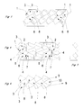
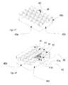
- Fig. 1 a single triple of the wide-angle mirror structure of the reflector, according to claim 1.
- the triple consists of three mirror surfaces (1, 2, 3), which are almost at right angles to each other, namely between 89 ° and 91 °.
- the slight deviations of 90 ° are due to the different refractive properties of the coming to processing plastics or glasses and the different shrinkage behavior of the materials required for tooling vorrauseilenden angle correction.
- Striking is the shape of the mirror surface (3), which is an uneven quadrilateral.
- This form arises in an inventive Wide-angle structure of the reflector, if the structure in the horizontal to both sides should be wide, so the angle of inclination of the triple axes to the incidence of the reflector surface for the one group of the triple + 5 ° and should be for the second triple group -5 °. It should be noted that it is of course possible to add further triples with different angles of inclination of the triple axes of the wide-angle structure, for example with an inclination angle of 0 ° or about +/- 15 °.
- the two triple partial surfaces, the mirror surfaces (2 and 3), are substantially larger and longer than the triple partial area 1.
- the extended Tripelteil configuration invention (2) makes the Ankleuchtungsweitwinkltechnik in the Fig. 3 horizontal, the triple part surface (3) in a substantially smaller vertical direction. See also the table of the Fig. 33 ,
- the center of the triple is the lowest point (4), which touches all three mirror surfaces.
- the footprint of the triple projected on a plane is an uneven hexagon.
- the shape of the triple is such that, with other similar triples, it forms a wide-angle mirror structure of the reflector (FIG. FIG. 3 and FIG. 4 ), which can capture the incident light from two opposite directions.
- the light entry surface (17) of the reflector is not positioned to scale here.
- the incidence slot (16) to the light entry surface (17) corresponds to a direct angle of incidence of the light at horizontal and vertical 0 °.
- the triple axis (18) of the triple is in this example, pointing away from the entrance slot to the right by about -5 °, inclined towards the triple section area (2).
- minus values are slope values pointing to the right for the observer, plus values are left-leaning slope values.
- the inclination could also be made to the edge of the triple, which is formed by the triple partial surfaces (2 and 3). It is important for the present invention that the inclination of the triple axis takes place in the direction of the extended triple partial surface or partial surfaces, or to the triple edge, which is formed from these extended partial surfaces. For thus the light trapping effect of the extended triple partial areas according to the invention becomes effective for the wide angle range.
- Fig. 2 a single triple of the wide-angle mirror structure of the reflector, this triple to a segment, see Fig. 20 and Fig. 21 , of the Wide-angle mirror structure is one that is aligned only on one side for the illumination wide-angle, as in the Fig. 7 to 10 shown.
- This triple consists of three mirror surfaces (1, 2, 5), which in turn are almost at right angles to each other. He is like the triple in Fig. 1 with its triple axis inclined by -5 ° to the right towards the triple surface 2.
- the shape of the triple part surfaces, mirror surfaces (2 and 5), are each elongated rectangles.
- the center of the triple is the lowest point (4).
- the footprint of the triple projected on a plane is an uneven hexagon.
- the shape of the triple is such that, with other similar triples, it forms a wide-angle mirror structure of the reflector (FIG. Fig. 7 and Fig. 8 ), which receives and retroflects the incident light predominantly from a spatial direction to the right of the incidence slot.
- Fig. 3 a wide - angle mirror structure of the reflector, which consists of triples of the Fig. 1 is joined together. Due to the perspective view, the mirror surfaces (2 and 7) of the Fig. 4 not visible.
- the mirror surfaces (1) and (3) show the triple of the first orientation.
- the mirror surfaces (6) and (8) show the triples of the second orientation in their rotated by 180 ° position relative to the triplets of the first orientation.
- the triples of a same orientation are arranged in rows. It alternate rows with opposite orientation. The orientation of the triple roughly determines the spatial direction from which it preferably receives light.
- the inclination angle of the triple axis with respect to the incidence solder is indicated by minus when the inclination in the figure for shows the viewer to the right and indicated by plus, if the inclination in the figure points to the left.
- Fig. 4 the wide angle mirror structure of the reflector of Fig. 3 in the view from above and thus the projection of all edges on a base.
- Fig. 5 the section through the wide-angle mirror structure of the reflector of the Fig. 4 , The cut passes through the opposing triple rows.
- Fig. 6 rotated the wide-angle mirror structure of the reflector in space so that all the mirror surfaces (3) of the triple of the first orientation (9) with the mirror surfaces (8) of the triple of the second orientation (10) show a closed specular surface for the viewer.
- the wide - angle mirror structure of the reflector is made up of the triplets of the Fig. 1 seamlessly put together.
- Fig. 7 the wide - angle mirror structure of the reflector, which is aligned on one side to the right and the triples of the Fig. 2 is joined together.
- a mirror surface (12) of Fig. 8 not visible.
- Fig. 8 the same wide angle mirror structure of the reflector Fig. 7 in the view from above and thus the projection of all edges on a base. All mirror surfaces of the triple are rectangles. The mirror surfaces (11, 12, 13) are arranged around the triple center (14). All triples are evenly aligned and therefore receive the light predominantly from the right side of the incidence slot.
- Fig. 9 the section through the wide-angle mirror structure of the reflector of the Fig. 8 , The cut passes through all arranged in the same orientation triples.
- Fig. 10 the wide angle mirror structure of the reflector of Fig. 7 rotated in the room so that all the mirror surfaces (13) of the triples of the same orientation (15) show a closed-looking area for the viewer as a single large mirror.
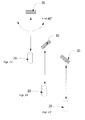
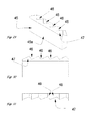
- Fig. 11 the principle of the triple with the extended Tripelteil relations (2). These are opposite to the two other triple sub-surfaces in an almost right angle, shown in this two-dimensional sketch as a line (23). From the incidence slot (16) of the light entry surface (17), the triple axis (18) deviates by, for example, 5 °. Here the triple axis is inclined towards the extended triple part surface (2).
- the light transmitter (24) of the reflex sensor transmits the light beam (26), which finds reference points on the extended triple part surface (2) within the triple, which allows a retroflexion of the light via the beam path (28) to the receiver (25). Even if the transmitter and receiver are replaced in this example, the beam path results in the opposite direction.
- Fig. 12 the sensor (29), which can observe the reflectors (30) in a horizontal opening angle of greater than 80 °.
- Fig. 13, Fig. 14 and Fig. 15 the sensor (29), which can observe the reflectors even with rotation of more than +/- 40 ° deviating from the beam path between the sensor and the reflector.
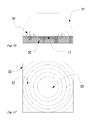
- the reflector (30) on the light entrance side (17) was additionally surface-structured with a Fresnel lens.
- the Fresnel lens enhances the ability of the Reflectors for Weitwinkltechnik.
- the theoretical lens mold (31) has a flattened in the center arc and determines the shape of the linearly applied in this example in circles Fresnel structure.
- the Fresnel structure can be micronized with known technique manufacture in the cutting process.
- Fig. 17 the reflector (30) of Fig. 16 in view of the light entrance surface (17) with the linear circles of the Fresnel structure (32) and the planar center (33) of the surface of the light entry side (17), which was not patterned.
- the Fresnel lens can also have a completely different shape.
- the reflector may be curved in itself or only the light entrance side.
- Fig. 18 the reflector (30), in the view of the light entry surface, with a division of the reflex structure in the segments (35) and (36).
- the reflector (30) as viewed from the light entry surface, is divided into numerous segments which point in very different directions with the extended triple subareas, for example (38) and (39). But it can also be added segments whose triples are not inclined, so that their triple axis corresponds to the incidence slot to the reflector surface.
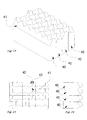
- Fig. 20 to Fig. 31 show the tool production for the production of wide-angle reflectors using the Gubela plate method.
- Fig. 20 a tool element (40), which may be formed as a glass body and a reflector element itself, with a chamfer, which forms a virtually unlimited triple partial surface (41).
- the plate-shaped tool element is notched at the upper edge. The edges of the notches form the two further triple partial surfaces (42) and (43) in FIG Fig. 25 visible, noticeable.
- Fig. 21 the tool element from the broad side with the chamfer (41).
- Fig. 22 the tool element from the narrow side with the angle (44), which determines the position of the notch. If the triple axis is to be inclined to the large triple part surface (41) by, for example, 5 °, an angle of approximately 30 ° should be used here relative to the light entry surface of the reflector.
- Fig. 23 shows the strand-shaped tool element in the view perpendicular to the light entry surface.
- the over the entire length of the strand running Tripelteil preparation faces the triple partial surfaces (42) and (43). All Tripelteil vom are almost at right angles to each other.
- Fig. 24 a complete reflector structure composed of the four tool elements (40).
- Fig. 25 equals to Fig. 24 viewed from the Lichteinfallslot.
- Fig. 26 the block of four tool elements in section.
- Fig. 27 the negative of the Fig. 24 , which corresponds to the galvanic impression and can be used as a metallic reflector or as a tool structure for the molding of wide-angle reflectors.
- the negative is a suitable retro-reflector.
- Marked are the triple partial surfaces (42) and (43).
- the triple part surface (41) is not visible.
- the outer edges of the negative are marked (40a) and (40b) and the concealed outer edge (40c), so that in the following Fig. 28 can detect the rotation of the negative in relation to the viewer.
- Fig. 28 the negative turned to the viewer Fig. 27 with the outer edge (40b) and the now visible outer edges (40c).
- the elongated Tripelteil lake (41) according to the invention extend in their width over the entire length of the negative.
- the triple partial surfaces (42) and (43) are at almost right angles to the triple partial surface (41).
- the visible part in this representation (41 a) and the non-visible part (41 b) shown the actual effective Tripelteil configuration (41) to the two marked Tripelteil lake (42) and (43) suitable reference points to light from far Capture the angle of illumination.
- the construction with the Gubela strands allows wide-angle triplets of the group of fullcubetripel associated with a very large light capture surface for wide-angle light. Because the large triple sub-area (41) can provide for several triples at the same time overlapping reference surfaces, which is formed from the sum of all reference points that can capture light and this can pass to the other triple sub-surfaces for retroflexion.
- Fig. 29 to Fig. 31 show yet another variant of Gubela strands to make even more extended light capture surfaces for a second spatial direction, for example, a vertical.
- FIG. 29 the tool element (45), the tool element (40) from Fig. 22 is similar. However, the notches (46) that meet the chamfer (47) are formed with non-uniform sides, which is in FIG Fig. (30 ) becomes visible.
- Fig. 30 the tool element in longitudinal section with the indicated chamfer (47) and the non-uniform notches (46).
- the edges (48) and (49) of the notches (46) form the two triple partial surfaces, which are almost at right angles to the chamfer (47), which corresponds to the third triple part surface
- Fig. 31 the view of the tool element from the light entrance side of the entrance slot accordingly.
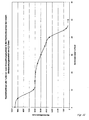
- Fig. 32 the reflectance values of an exemplary reflector made of PMMA, which is the retroflective structure of the Fig. 3 corresponds, as a function of the angle of illumination in the horizontal axis of the Fig. 4 at an observation angle of 0.2 °.
- the measuring method The vertical angle is 0 °.
- the Xoffset is 0 °, the Yoffset 0.5 °.
- the return values are entered in mcd / lx.
- the test sample "IMOS Wide Angle 1" is commissioned by the company IMOS Gubela GmbH, Renchen, Germany, for the inventor and consists of a 50x50 mm reflector plate with welded back box.
- the reflective surface is about 47x47 mm in size and consists of the structures of the invention Fig. 3 with significantly extended triple part surfaces whose maximum power lies somewhat from the horizontal.
- the reflex structure consists of triples, which are set in tracks and whose extended triple side per track is rotated by 180 °. The inclination of the triple axes are inclined at 5 ° to the extended triple surfaces.
- the triples are designed as Mikrocubetripel whose smallest edge length is about 1 mm.
- the triple structure is suitable for sensors with polarization filters or laser sensors.
- the construction of the structure of the test specimen is also suitable for the production of microstructured reflective foils.
- Fig. 33 the table of photometric measurement results in detail of Fig. 32 , It means (test point), specifying the observation angle 0.2 ° followed by the angles of illumination in degrees at horizontal (H) and vertical (V). (HV) is the angle of illumination at horizontal and vertical 0 °. It can be seen that the test sample was designed for horizontal Weitwinkltechnik out.
Abstract
Description
Die Erfindung betrifft ein Verfahren und die Ausbildung eines geeigneten Reflektors zur weitwinkligen Beobachtung einer Reflexfläche mittels eines Reflexsensors, der auch mit Polarisationsfiltern ausgerüstet sein darf oder als Laserreflexsensor arbeiten kann.The invention relates to a method and the formation of a suitable reflector for wide-angle observation of a reflective surface by means of a reflex sensor, which may also be equipped with polarizing filters or work as a laser reflection sensor.
Das Weitwinkelsensorsystem mit Tripelreflektor besteht aus einer Lehre zur Wahl des Beobachtungswinkels und eines Tripelreflektors, der aus einer Vielzahl von Tripeln besteht. Wobei die um das Tripelzentrum angeordneten Tripelteilflächen nämlich Spiegelseiten, nahezu im Rechten Winkel zueinander stehen und die Achse der Tripels wechselweise um -5° und +5° oder mehr vom Einfallslot der Reflektoroberfläche abweicht. Besonderes Merkmal der Tripel ist die erhebliche Verlängerung mindestens einer Tripelfläche.The triple-angle wide-angle sensor system consists of a doctrine for selecting the viewing angle and a triple reflector consisting of a plurality of triplets. The triple partial areas arranged around the triple center are mirror sides, almost at right angles to each other, and the axis of the triple alternates by -5 ° and + 5 ° or more from the incidence slot of the reflector surface. A special feature of the triples is the considerable extension of at least one triple surface.
Ziel des Weitwinkelsensorsystems mit Tripelreflektor ist es, ein Reflexsensorsystem zu schaffen, mit dem eine Fläche beobachtet werden kann mit einem Öffnungswinkel von 80° und mehr bei einem Rückstrahlwert an jedem Beleuchtungswinkel der beobachteten horizontalen Fläche von mindestens 3.000 mcd/Ix. Außerdem können mit diesem System sich bewegende Körper im Raum, zum Beispiel Fahrzeuge oder Transportgondeln beobachtet werden, auch wenn diese Körper ihren Winkel zum Beobachter verändern, zum Beispiel wenn eine Fördergondel in einer Kurve geführt wird. Erst dadurch, dass von dem zu beobachtenden Körper immer ein Reflexsignal in seiner Intensität stark genug empfangen wird von mindestens 3.000 mcd/lx, kann auch eine angeschlossene Messtechnik, zum Beispiel zur Entfernungsmessung oder Positionsvermessung zuverlässig arbeiten.The aim of the triple-angle wide-angle sensor system is to provide a reflex sensor system capable of observing an area having an opening angle of 80 ° and more at a retroreflective value at each illuminance angle of the observed horizontal area of at least 3,000 mcd / lx. In addition, with this system moving bodies in space, for example vehicles or transport gondolas, can be observed, even if these bodies change their angle to the observer, for example when a conveyor nacelle is guided in a curve. Only by the fact that from the body to be observed always a reflex signal in its intensity is received strong enough of at least 3,000 mcd / lx, can also be a connected measurement technique, for example, for distance measurement or position measurement work reliably.
Das Problem ist, dass es bisher für die Aufgaben der Reflexsensorik keine qualitativ ausreichenden Reflexflächen auf dem Markt gibt, die ein intensives Retroflexsignal beständig liefern, besonders dann nicht, wenn die Reflexfläche mit 40° und mehr abweichend vom Lot positioniert wird. Die auf dem Markt befindlichen Rückstrahler oder Reflexfolien, so weit sie weitwinklige Eigenschaften haben, sind konzipiert für den Straßenverkehr, für reflektierende Schilder oder Personenschutzrückstrahler an Kleidern. Diese reflektierenden Strukturen erzeugen eine breitbandige Verteilung des reflektierten Lichts. Dadurch reicht ihre reflektierte Lichtenergie nicht aus, Reflexsensoren gebündelte zuverlässige Retroflexsignale zu geben. Für Reflexsensoren muss möglichst der größte Teil des Lichtes retroflektiert werden zielgerichtet zum Empfänger.The problem is that so far there are no high-quality reflex surfaces on the market for the tasks of the reflex sensor, which provide an intense Retroflexsignal resistant, especially not if the reflective surface is positioned at 40 ° and more deviating from the Lot. The reflectors or reflective films on the market, as far as they have wide-angle properties, are designed for road traffic, for reflective signs or personal protection reflectors on clothes. These reflective structures produce a broadband distribution of the reflected light. As a result, their reflected light energy is insufficient to give reflex sensors bundled reliable retroflex signals. For reflex sensors, as much of the light as possible has to be retroflected in a targeted manner to the receiver.
Erst durch eine konstante, hohe Retroflexleistung wird es möglich, den Sensor zusätzlich mit einem Polarisationfiltersystem zu versehen, das naturgemäß die Hälfte bis zu zwei Drittel des gesendeten Lichtes verbraucht, so dass diese Energie nicht mehr für den Empfänger des Sensors zur weiteren Interpretation zur Verfügung steht. Das Polarisationfiltersystem dient vor allem dazu, das vom Sensor ausgesandte Licht und dann über den Retroflektor in seiner Polarität gedrehte und zurückgeworfene Licht zu unterscheiden von Fremdlicht oder Reflexionen, die von anderen Körpern im Raum ausgehen können. Das erfindungsgemäße Weitwinkelsystem mit seinem Tripelreflektor besonderer Bauart ermöglicht den Betrieb des Sensors mit Polarisationsfiltersystem.Only by a constant, high Retroflexleistung it becomes possible to provide the sensor additionally with a polarization filter system, which naturally consumes half to two thirds of the transmitted light, so that this energy is no longer available for the receiver of the sensor for further interpretation , The purpose of the polarization filter system is above all to distinguish the light emitted by the sensor and then the polarity of the retro-reflector and reflected light from extraneous light or reflections that can emanate from other bodies in the room. The wide-angle system according to the invention with its triple reflector special design allows the operation of the sensor with polarization filter system.
Außerdem kann dieser neuartige Tripelreflektor auch mit bekannter Technologie als Mikrocubereflektor ausgebildet werden, wie er besonders für die Lasersensorik oder Folientechnik erforderlich ist. Die Anforderungen zur Lasersensorik sind dazu vom Erfinder in der
Der Stand der Technik kennt das würfelförmige, reflektierende Spiegelsystem, dass in der Messtechnik als Perkin-Elmer-Pyramide bekannt ist und bei Rückstrahlern heute als Fullcube bezeichnet wird. Ein Fullcube-Tripel besteht aus drei quadratischen Spiegeln, die zueinander im Rechten Winkel stehen und das Licht zur Lichtquelle retroflektieren. In der
In der
Der in der vorliegenden Erfindung beschriebene Reflektor und die Herstellung der Werkzeuge basiert zwar auf den bekannten Verfahren zur Herstellung von Tripelreflektoren, wählt aber eine neuartige Form aus, die dem Fullcube nahe kommt.Although the reflector described in the present invention and the manufacture of the tools based on the known method for the production of triple reflectors, but selects a novel shape that comes close to the full cube.
Es gibt auch andere Tripelformen, wie zum Beispiel die dreiseitige Pyramide. Hier muss aber der Abwandlung des Fullcubes der Vorzug gegeben werden, weil er grundsätzlich einen wesentlich geringeren Streuverlust hat als die Pyramide. Pyramidale Tripelstrukturen lassen sich aus einer ebenen gemeinsamen Fläche schneiden, hingegen benötigen Fullcube-Tripel im Werkzeugbau die Anordnung einer Vielzahl von Bauelementen, um große strukturierte Flächen aus einer Vielzahl von Tripeln darzustellen. Die Fertigungsmethoden und ihre Vor- und Nachteile bei der Herstellung von Tripeln sind dem Fachmann bekannt und brauchen hier nicht wiederholt zu werden.There are also other triple forms, such as the three-sided pyramid. Here, however, preference must be given to the modification of the fullcube because, in principle, it has a much lower scattering loss than the pyramid. Pyramidal triple structures can be cut out of a flat common area, whereas fullcube triplets in toolmaking require the arrangement of a large number of components in order to represent large structured areas made up of a large number of triplets. The production methods and their advantages and disadvantages in the production of triples are known in the art and need not be repeated here.
Die Erfindung macht sich die Erfahrungen zu Nutze, die man mit der Herstellung und Verwendung von Fullcube-Tripeln in der Technik gemacht hat. Der Fullcube-Tripel hat die vorzügliche Eigenschaft, einfallendes Licht in einem weiten Toleranzbereich des Einfallwinkels zu empfangen und nahezu vollständig an die Lichtquelle zu retroflektieren. Die Retroflexion erfolgt über die Lichtspiegelung auf den drei quadratischen Flächen des Fullcube-Tripels. Diese Winkeltoleranz für das einfallene Licht wird in der praktische Anwendung heute bei den meisten Reflexionslichtschranken genutzt. Die Montage und Ausrichtung der Rückstrahler winkelgerecht zum Sender/Empfängersystem ist einfach und fehlertolerant. Auch Strahlbewegungen durch Vibrationen werden meist von diesem Reflexionselement mit Fullcube-Tripeln toleriert. Bei der Verwendung von Laserlichtsensoren wird die Anwendung von Tripeln als Reflexionselement sehr schwierig, weil der Laser bei unsachgemäßer Anwendung Informationen über seine Bewegung auf der Retroflexionsstruktur und Informationen über die Gestalt der Retroflexionsstruktur liefert, statt über den zu beobachtenden Raum zwischen Sender/Empfänger und Retroflexionsspiegel. Die
Im weiteren Text wird nur noch von Tripelsystemen gesprochen, die dem Fullcube zugeordnet werden können. Denn man muss unbedingt bei Tripeln unterscheiden zwischen den pyramidalen Tripeln, die aus einer Grundfläche geschnitten werden können und Fullcube-Tripeln, die dagegen nur durch Zusammenfügen von Teilsegmenten herstellbar sind.The rest of the text only speaks of triple systems that can be assigned to the fullcube. Because it is essential to distinguish between triples, which are pyramidal triples that can be cut from a base area, and fullcube triples, which can only be produced by joining subsegments.
Die Herstellung der Rückstrahlertechnik kennt Fullcube-Tripel, deren Tripelachse abweichend vom Einfallslot der Reflektoroberfläche ausgerichtet ist.The production of the retroreflective technology knows Fullcube triple, whose triple axis is deviating from the incidence of the reflector surface aligned.
Während beim Fullcube, der sogenannten Perkin-Elmer-Pyramide die Teilflächen der Tripel quadratisch sind, verwendet das erfindungsgemäße Weitwinkelsensorsystem als Tripelreflektor eine besondere Variation des Fullcube-Tripels, bei dem mindestens eine Tripelteilfläche wesentlich größer ist als die kleinste Tripelteilfläche.While the Fullcube, the so-called Perkin Elmer Pyramid the Squares of the triples are square, the wide angle sensor system according to the invention uses as a triple reflector a particular variation of the full cube triple, in which at least one triple partial area is substantially larger than the smallest triple partial area.
Diese vergrößerte, verlängerte Tripelteilfläche verhilft dazu, auch sehr weitwinklig einfallendes Licht aufzufangen und an die übrigen Tripelteilflächen weiterzugeben, so dass das Licht in Richtung zur Lichtquelle retroflektiert wird. Es entsteht ein Tripel, der völlig überraschend in der Praxis wesentlich weitwinkliger arbeitet, als man erwarten konnte.This enlarged, extended triple part surface helps to catch even very wide-angle incident light and pass it on to the other triple partial areas, so that the light is retroflected in the direction of the light source. The result is a triple, which works completely surprisingly in practice substantially weitwinkliger, as one could expect.
Dagegen werden zum Beispiel bei Rückstrahlern für Kraftfahrzeuge weitwinklig wirkende Reflexflächen durch Wölbung des gesamten Reflektors dargestellt, indem man die Reflektorfläche aus einer Vielzahl einzelner Reflexstifte bildet, die in die gewünschten Richtungen blicken, so dass mittels einer galvanischen Abformung dann ein Weitwinkelreflektor in Kunststoff abgeformt werden kann. Die dabei entstandenen Tripel haben dann immer noch gleich große, nahezu quadratische Tripelteilflächen. Die Weitwinkligkeit des entstandenen Reflektors beruht dann nur darauf, dass Tripel mit verschieden ausgerichteten Tripelachsen kombiniert wurden, so dass je nach Einfallswinkel des Lichtes immer nur ein sehr kleiner Teil der Tripel arbeitet, deren Achsen in die Lichtrichtung blicken. Die Retroflexleistung ist entsprechend sehr niedrig.In contrast, for example, in retro-reflectors for motor vehicles wide-angle reflective surfaces represented by curvature of the entire reflector by forming the reflector surface of a plurality of individual reflex pins that look in the desired directions, so that by means of a galvanic impression then a wide-angle reflector can be molded into plastic , The resulting triples then still have the same size, almost square Tripelteilflächen. The Weitwinkligkeit of the resulting reflector is then based only on the fact that triples were combined with differently oriented triple axes, so that depending on the angle of incidence of the light only a very small part of the triple works, whose axes look in the direction of light. The retroflex performance is correspondingly very low.
Für den erfindungsgemäßen Reflektor sind Fertigungsmethoden gewählt worden, die eine besondere Tripelfläche erzeugen, deren Charakter sich deutlich von Reflexflächen unterscheidet, welche durch Stifte gebildet wurden. Sind bei Fullcube-Reflektoren, die aus Stiften dargestellt werden, die Tripelteilflächen etwa gleich groß, quadratisch, so sind bei der besonderen Variation des Fullcube-Tripels, wie er im erfindungsgemäßen Reflektor verwendet wird, je Tripel mindestens eine Tripelteilfläche wesentlich größer ist als die kleinste Tripelteilfläche des Tripels. Erst die wesentlich vergrößerte, nämlich verlängerte Tripelteilfläche ermöglicht sehr weitwinklig einfallendes Licht einzufangen und die in Fig. 34 und die Tabelle der Fig. 35 gezeigten hervorragenden Rückstrahlwerte zu erzielen.For the reflector according to the invention manufacturing methods have been chosen that produce a special triple surface, the character of which differs significantly from reflective surfaces, which are formed by pins were. Are in Fullcube reflectors, which are represented by pins, the triple partial areas about the same size, square, so are in the particular variation of the full cube triple, as used in the reflector according to the invention, each triple at least a triple partial area is much larger than the smallest Tripelteilfläche the triple. It is only the substantially enlarged, namely prolonged triple partial area, which makes it possible to capture incident light at very wide angles and to achieve the excellent reflection values shown in FIG. 34 and the table of FIG. 35.
Einige Zeichnungen und Darstellungen dieser Erfindungsbeschreibung ähneln der
Die erfindungsgemäße besondere Tripelform mit vergrößerter, verlängerter Tripelteilfläche erreicht man bei Darstellung der Tripel im Plattenverfahren, das in der
Die gewünschte verlängerte Tripelteilfläche entsteht beim Kerben der Werkzeugelementplatten bei Anwendung des Stimson Plattenverfahren durch das schräge keilförmige Einschneiden in den Platten (
Eine noch ebenfalls lange, aber dazu in der Breite nahezu unbegrenzte Tripelteilfläche erhält man bei Verwendung des Plattenverfahrens, wie es Gubela in der
Beim Gubela Verfahren ist eine Ausrichtung der Tripelachsen von 5° abweichend vom Einfallslot der Reflektoroberfläche sehr vorteilhaft für das erfindungsgemäße Weitwinkelsensorsystem. Erhält man doch bei Darstellung des Reflektors mit diesem Verfahren zusätzlich eine Weitwinkligkeit nicht nur in der Horizontalen, sondern auch in der Vertikalen.In the Gubela method, an orientation of the triple axes of 5 ° different from the incidence solder of the reflector surface is very advantageous for the wide-angle sensor system according to the invention. In addition, when viewing the reflector with this method, one obtains additionally a wide angle not only in the horizontal, but also in the vertical.
Die Erfindung schlägt einen Weitwinkelsensor mit einem Reflektor vor, bei dem zu einem Lichtsender ein Lichtempfänger so eingesetzt wird, dass der Beobachtungswinkel möglichst klein ist. Der Beobachtungswinkel von 0° bedeutet, dass der Lichtempfänger zum Lichtsender so positioniert ist, dass das vom Reflektor retroflektierte Licht auf der gleichen Achse empfangen wird, wie es gesendet wurde. Solche Anordnungen sind in der Sensorik bekannt und werden zum Beispiel durch Verwendung von halbdurchlässigen Spiegeln oder Strahlteilern gelöst. Allerdings geht bei dieser Anordnung etwas Lichtenergie verloren, weil auch unerwünschte Strahlengänge entstehen. Um solche aufwendigen optischen Einrichtungen zu vermeiden, genügt es für das erfindungsgemäße Sensorsystem den Lichtempfänger möglichst nahe an die Achse des Lichtsenders zu positionieren, so dass ein Beobachtungswinkel von größer 0°, zum Beispiel 0,2°, und nicht mehr als 1° entsteht. Dann kann der Reflektor über eine Horizontale von etwa +40° bis -40° beobachtet werden, was einem Öffnungswinkel der vom Sensor beobachteten Fläche von etwa 80° entspricht und einer dauernden Rückstrahlleistung des Reflektors von über 3.000 mcd/lx. Durch Veränderung der Tripelachsen einiger Tripel im Reflektor bis zu etwa +/-15° und mehr kann der Öffnungswinkel noch erheblich erweitert werden. Denn mit dem Kippen der Tripelachse weg vom Einfallslot der Reflektoroberfläche, also mit der Vergrößerung der Tripelachse, vergrößert sich auch die verlängerte Tripelteilfläche, die das Licht wesentlich besser einfängt. Die verblüffende Wirkung des erfindungsgemäßen Systems beruht auf dieser besonderen Tripelgestalt des Reflektors, die die Weitwinkligkeit des Reflektors nicht nur durch das Verschwenken der Tripelachse erzielt, sondern durch die damit verbundene Vergrößerung der verlängerten Tripelteilfläche. So erzielt man bei einem horizontalem Verschwenken der Tripelachsen um +/-5° bereits eine horizontale Weitwinkligkeit von mehr als 40°, dabei bleibt aber die äußerst hohe Reflexleistung von über 9.000 mcd/lx bei horizontal und vertikal 0° bestehen.The invention proposes a wide-angle sensor with a reflector in which a light receiver is used to a light transmitter so that the observation angle is as small as possible. The viewing angle of 0 ° means that the light receiver is positioned towards the light emitter so that the light retroreflected by the reflector is received on the same axis as it was transmitted. Such arrangements are known in the sensor art and are solved, for example, by using semi-transparent mirrors or beam splitters. However, some light energy is lost in this arrangement, because even unwanted beam paths arise. To avoid such complex optical devices, it is sufficient for the invention Sensor system to position the light receiver as close to the axis of the light emitter, so that an observation angle greater than 0 °, for example, 0.2 °, and not more than 1 ° is formed. Then, the reflector can be observed over a horizontal of about + 40 ° to -40 °, which corresponds to an opening angle of the surface observed by the sensor of about 80 ° and a constant retroreflectance of the reflector of over 3,000 mcd / lx. By changing the triple axes of some triples in the reflector up to about +/- 15 ° and more, the opening angle can be significantly extended. Because with the tilting of the triple axis away from the incidence slot of the reflector surface, ie with the enlargement of the triple axis, also increases the extended triple part surface, which captures the light much better. The amazing effect of the system according to the invention is based on this particular triple shape of the reflector, which achieves the Weitwinkligkeit the reflector not only by pivoting the triple axis, but by the associated enlargement of the extended triple partial area. Thus, with a horizontal pivoting of the triple axes by +/- 5 ° already achieved a horizontal Weitwinkligkeit of more than 40 °, but this remains the extremely high reflectivity of over 9,000 mcd / lx at horizontal and vertical 0 ° exist.
Die Erfindung ermöglicht also ein Weitwinkelsensorsystem mit Tripelreflektor zu schaffen durch einen Beobachtungswinkel des Weitwinkelsensors von 1° oder kleiner und der Gestaltung eines Tripelarrays für den Reflektor, der aus einer Vielzahl von Fullcube-Tripeln besteht, von denen die überwiegende Zahl von Tripeln mindestens eine wesentlich verlängerte Tripelteilfläche besitzen und deren Tripelachse um +/-5° oder mehr bezogen zum Einfallslot der Lichteintrittsfläche geneigt ist, und bei Verwendung eines Herstellverfahrens der Fullcube-Tripel mittels Stimson- Platten oder Gubela-Strängen, so dass über einen Anleuchtungswinkel von +/-40° oder mehr der Weitwinkelsensor über seinen gesamten Beobachtungswinkel von 80° oder mehr ein Retroflexsignal erhält, dessen Rückstrahlwert niemals unter 3.000 mcd/lx sinkt und so dass der Weitwinkelsensor auch mit einem Polarisationsfilter ausgerüstet werden kann. Zusätzlich kann der Reflektor auf der Lichteintrittsfläche mit einer Fresnellinse ausgerüstet werden, die die Anleuchtweitwinkligkeit erhöht.The invention thus makes it possible to provide a wide-angle sensor system with a triple reflector by an angle of view of the wide-angle sensor of 1 ° or smaller and the design of a triple array for the reflector, which consists of a plurality of Fullcube triples, of which the vast majority of triples extended at least one substantially Own triple-surface and the triple axis is inclined by +/- 5 ° or more relative to the entrance slot of the light entry surface, and when using a Fullcube triplet manufacturing method by means of Stimson plates or Gubela strands, so that over a viewing angle of +/- 40 ° or more the wide angle sensor receives a retroflex signal over its entire viewing angle of 80 ° or more, its reflectance value never drops below 3,000 mcd / lx and so that the wide-angle sensor can also be equipped with a polarizing filter. In addition, the reflector can be equipped on the light entry surface with a Fresnel lens, which increases the illumination angle.
Bei der Besprechung der Figuren werden weitere Details der Erfindung nachstehend dargestellt.In the discussion of the figures, further details of the invention are presented below.
Die geringfügigen Abweichungen von 90° sind wegen der unterschiedlichen Brechungseigenschaften der zur Verarbeitung kommenden Kunststoffe oder Gläser und dem unterschiedlichen Schrumpfverhalten der Werkstoffe erforderlich zur im Werkzeugbau vorrauseilenden Winkelkorrektur.The slight deviations of 90 ° are due to the different refractive properties of the coming to processing plastics or glasses and the different shrinkage behavior of the materials required for tooling vorrauseilenden angle correction.
Auffällig ist die Form der Spiegelfläche (3), die ein ungleichseitiges Viereck ist. Diese Form entsteht bei einer erfindungsgemäßen Weitwinkelstruktur des Reflektors, wenn die Struktur in der Horizontalen nach beiden Seiten weitwinklig sein soll, also der Neigungswinkel der Tripelachsen zu dem Einfallslot der Reflektoroberfläche für die eine Gruppe der Tripel +5° betragen soll und für die zweite Tripelgruppe -5° betragen soll. Es sei angemerkt, dass man natürlich weitere Tripel mit anderen Neigungswinkeln der Tripelachsen der Weitwinkelstruktur hinzufügen kann, zum Beispiel mit Neigungswinkel 0° oder etwa +/-15°.Striking is the shape of the mirror surface (3), which is an uneven quadrilateral. This form arises in an inventive Wide-angle structure of the reflector, if the structure in the horizontal to both sides should be wide, so the angle of inclination of the triple axes to the incidence of the reflector surface for the one group of the triple + 5 ° and should be for the second triple group -5 °. It should be noted that it is of course possible to add further triples with different angles of inclination of the triple axes of the wide-angle structure, for example with an inclination angle of 0 ° or about +/- 15 °.
Ein wesentliches Merkmal des Tripels ist, dass die beiden Tripelteilflächen, die Spiegelflächen (2 und 3), wesentlich größer und länger sind als die Tripelteilfläche 1. Denn es soll erfindungsgemäß mindestens eine Tripelteilfläche wesentlich verlängert werden in die Richtung des zu empfangenden Lichtes aus weitwinkliger Position. So leistet die erfindungsgemäße verlängerte Tripelteilfläche (2) die Anleuchtungsweitwinkligkeit in der
Das Zentrum des Tripels ist der tiefste Punkt (4), den alle drei Spiegelflächen berühren. Die auf eine Ebene projizierte Grundfläche des Tripels ist ein ungleichmäßiges Sechseck. Die Form des Tripels ist so beschaffen, dass er mit anderen gleichartigen Tripeln zu einer Weitwinkelspiegelstruktur des Reflektors (
Man kann bei der Neigung des Einfallslotes unterscheiden zwischen der Neigung zu den Flächen, in diesem besonderen Konstruktionsfall sogar bezogen auf drei unterschiedliche Flächen, und zur Neigung zu den Kanten des Tripels, wobei ebenfalls drei unterschiedliche Kanten zu berücksichtigen wären. Für das Verständnis der Erfindung ist ein detaillierteres Koordinatensystem für die Neigung der Tripelachse nicht erforderlich.In the case of the inclination of the incidence solder, it is possible to differentiate between the inclination to the surfaces, in this particular design case even with reference to three different surfaces, and to the inclination to the edges of the triple, likewise taking into account three different edges. For the understanding of the invention, a more detailed coordinate system for the inclination of the triple axis is not required.
In den folgenden Beispielen wird von einer Neigung zu der Tripelteilfläche (2) ausgegangen.In the following examples, an inclination to the triple partial area (2) is assumed.
Zur Erläuterung, Minuswerte sind für den Betrachter nach rechts weisende Neigungswerte, Pluswerte sind nach links weisende Neigungswerte.By way of illustration, minus values are slope values pointing to the right for the observer, plus values are left-leaning slope values.
Aber natürlich könnte die Neigung auch zu der Kante des Tripels ausgeführt werden, die von den Tripelteilflächen (2 und 3) gebildet wird. Wichtig ist für die vorliegende Erfindung, dass die Neigung der Tripelachse in Richtung der verlängerten Tripelteilfläche oder Teilflächen hin erfolgt, oder zu der Tripelkante, die aus diesen verlängerten Teilflächen gebildet wird. Denn damit wird die erfindungsgemäße Lichteinfangwirkung der verlängerten Tripelteilflächen für den Weitwinkelbereich wirksam.But of course, the inclination could also be made to the edge of the triple, which is formed by the triple partial surfaces (2 and 3). It is important for the present invention that the inclination of the triple axis takes place in the direction of the extended triple partial surface or partial surfaces, or to the triple edge, which is formed from these extended partial surfaces. For thus the light trapping effect of the extended triple partial areas according to the invention becomes effective for the wide angle range.
Die Form der Tripelteilflächen, Spiegelflächen (2 und 5), sind jeweils gestreckte Rechtecke. Das Zentrum des Tripels ist der tiefste Punkt (4). Die auf eine Ebene projizierte Grundfläche des Tripels ist ein ungleichmäßiges Sechseck. Die Form des Tripels ist so beschaffen, dass er mit anderen gleichartigen Tripeln zu einer Weitwinkelspiegelstruktur des Reflektors (
In diesen Beispielen wird der Neigungswinkel der Tripelachse bezogen zum Einfallslot mit Minus angegeben, wenn die Neigung in der Figur für den Betrachter nach rechts zeigt und mit Plus angegeben, wenn die Neigung in der Figur nach links weist.In these examples, the inclination angle of the triple axis with respect to the incidence solder is indicated by minus when the inclination in the figure for shows the viewer to the right and indicated by plus, if the inclination in the figure points to the left.
Diese Tripelanordnung mit +5° Neigung der Tripelachse der hintersten Reihe von Tripeln kombiniert mit Tripeln der zweiten Reihe, deren Winkelachsen der Tripel um -5° geneigt sind ergeben eine Weitwinkligkeit von 40° horizontal nach beiden Seiten des Einfallslots der Reflektoroberfläche. Das bedeutet, dass der Reflektor über einen Öffnungswinkel von mehr als 80° wirksam ist. Obwohl in diesem Beispiel alle Tripelachsen um -5° oder +5° geneigt sind, ergibt diese Tripelanordnung bei senkrechtem Lichteinfall folgend dem Einfallslot eine Reflexleistung die nahezu 100% eines Hochleistungs-Fullcube-Reflektors entspricht, dessen Tripelachsen nicht geneigt sind. Das ist ein unerwartetes Ergebnis dieser erfindungsgemäßen Konstruktion, dass die ungewöhnlich hohe Anleuchtungsweitwinkligkeit des erfindungsgemäßen Reflektors nicht durch Leistungsverlust in lotrechter Lichteinstrahlung erkauft werden muss.This triple arrangement with + 5 ° tilt of the triple axis of the rearmost row of triples combined with triplets of the second row whose angular axes of the triple are tilted by -5 ° give a Weitwinkligkeit of 40 ° horizontally to both sides of the entrance slot of the reflector surface. This means that the reflector is effective over an opening angle of more than 80 °. Although in this example all triple axes are tilted by -5 ° or + 5 °, this triple arrangement following vertical incidence following the incidence slot results in a reflectivity which corresponds to nearly 100% of a high power fullcube reflector whose triple axes are not inclined. This is an unexpected result of this construction according to the invention, that the unusually high illumination wide-angle of the reflector according to the invention does not have to be paid for by loss of power in perpendicular light irradiation.
Bei der erfindungsgemäßen Wirkung der Anleuchtungsweitwinkligkeit erweitern wahrscheinlich auch Beugungseffekte an der Kante, gebildet aus (2) und (17) der verlängerten Tripelteilfläche die Möglichkeiten der Anleuchtung.In the case of the illumination wide-angle effect according to the invention, diffraction effects on the edge, formed from (2) and (17) of the extended triple partial area, probably also increase the possibilities of illumination.
Auch kann der Reflektor in sich selbst zusätzlich gewölbt sein oder nur die Lichteintrittseite.Also, the reflector may be curved in itself or only the light entrance side.
Wählt man die nach zwei Seiten wirksame Struktur der
In dieser Figur wird dagegen gezeigt, dass einseitig ausgerichtete Strukturen der
Auch als Glaskörper mit der Lichteintrittseite von unten beleuchtet ist das Negativ ein geeigneter Retroflektor.Also illuminated as a glass body with the light entry side from below, the negative is a suitable retro-reflector.
Gekennzeichnet sind die Tripelteilflächen (42) und (43). Die Tripelteilfläche (41) ist nicht einsehbar. Die Außenkanten des Negativs sind mit (40a) und (40b) und der verdeckten Außenkante (40c) gekennzeichnet, damit man in der folgenden
Die Messmethode: Der Vertikalwinkel ist 0°. Um die Spiegelung auf der Lichteintrittsfläche des Reflektors auszublenden betragen der Xoffset 0°, der Yoffset 0,5°. Auf der x-Achse sind die Horizontalwinkel, auf der Y-Achse die Rückstrahlwerte in mcd/lx eingetragen. Das Prüfmuster "IMOS Weitwinkel 1" ist von der Firma IMOS Gubela GmbH, Renchen, Deutschland, für den Erfinder auftragsgefertigt und besteht aus einer 50x50 mm großen Reflektorplatte mit aufgeschweißtem Rückkasten. Die Reflexfläche ist etwa 47x47 mm groß und besteht aus den erfindungsgemäßen Strukturen der
The measuring method: The vertical angle is 0 °. To hide the reflection on the light entry surface of the reflector, the Xoffset is 0 °, the Yoffset 0.5 °. On the x-axis are the horizontal angles, on the Y-axis the return values are entered in mcd / lx. The test sample "
Die Bauweise der Struktur des Prüfkörpers ist wie alle in dieser Erfindung vorgeschlagenen Bauweisen der Tripelarrays auch für die Herstellung mikrostrukturierter Reflexfolien geeignet.The construction of the structure of the test specimen, like all the construction methods of the triple arrays proposed in this invention, is also suitable for the production of microstructured reflective foils.
Was sofort auffällt, ist der außergewöhnlich hohe Rückstrahlwert bei horizontal 0° von 9.510 mcd/lx. Damit übertrifft der Reflektor bereits die meisten am Markt befindlichen Rückstrahlflächen. Mit diesem Leistungswert ist er den zur Zeit leistungsbesten Kunststoff-Reflektoren am Markt, zum Beispiel den IMOS Microcube-Reflektoren, in der Leistung entsprechend. Man hätte erwarten können, dass ein weitwinkliger Reflektor wie in der Vergangenheit zwar wenn er denn wirklich über 40° hinaus weitwinklig wirkt, äußerst schlechte Rückstrahlwerte erbringt bei einem Anleuchtungswinkel von horizontal/vertikal 0° . Denn bisherige, als Weitwinkel bezeichnete Fullcube-Tripelkonstruktionen verteilen die Lichtenergie falsch und sind nicht in der Lage, in einem weiten Anleuchtungswinkel von über 80° leistungsstarke Retroflexion über 3.000 mcd/lx zu erzeugen.What is immediately noticeable is the exceptionally high retroreflective value at a horizontal 0 ° of 9,510 mcd / lx. This means that the reflector already surpasses most of the return surfaces on the market. With this performance value, it is in line with the currently best performing plastic reflectors on the market, for example the IMOS Microcube reflectors. One would have expected that, as in the past, a wide-angle reflector, if it really acts over an angle of more than 40 °, would yield extremely poor reflection values at an angle of horizontal / vertical 0 °. Previous full-cone triple-cone designs, known as wide-angle, have misplaced the light energy and are unable to produce high-performance retroflexions in excess of 3,000 mcd / lx over a wide illumination angle of over 80 °.
Bei einem Anleuchtungswinkel von 15° arbeiten bei dem erfindungsgemäßen Prüfmuster nur noch 50% der Tripel. Dennoch erreichen die Tripel aber immer noch 6.030 mcd/lx. So wird noch bei 40° Anleuchtungswinkel 3.510 mcd/lx erreicht.At a viewing angle of 15 ° only 50% of the triples work in the test pattern according to the invention. Nevertheless, the triples still reach 6,030 mcd / lx. So even at 40 ° angle of illumination 3.510 mcd / lx is reached.
Dieses Prüfmuster ist nur ein erster Beweis für die Richtigkeit der vorgetragenen Erfindung. Werden die in dieser Erfindung vorgetragenen beispielhaften Bauweisen der Gubela Stränge,
Man erkennt, dass das Prüfmuster auf die horizontale Weitwinkligkeit hin gestaltet wurde.
It can be seen that the test sample was designed for horizontal Weitwinkligkeit out.
Es folgen in der Anlage die
Claims (14)
Applications Claiming Priority (2)
| Application Number | Priority Date | Filing Date | Title |
|---|---|---|---|
| DE10216579A DE10216579A1 (en) | 2002-04-14 | 2002-04-14 | Wide-angle sensor system with triple reflector and production of the tools |
| EP03007645A EP1361460B1 (en) | 2002-04-14 | 2003-04-03 | Triple reflector and wide angle sensor system comprising the same |
Related Parent Applications (1)
| Application Number | Title | Priority Date | Filing Date |
|---|---|---|---|
| EP03007645A Division EP1361460B1 (en) | 2002-04-14 | 2003-04-03 | Triple reflector and wide angle sensor system comprising the same |
Publications (2)
| Publication Number | Publication Date |
|---|---|
| EP2012147A2 true EP2012147A2 (en) | 2009-01-07 |
| EP2012147A3 EP2012147A3 (en) | 2009-04-29 |
Family
ID=28458830
Family Applications (3)
| Application Number | Title | Priority Date | Filing Date |
|---|---|---|---|
| EP08164497A Withdrawn EP2012147A3 (en) | 2002-04-14 | 2003-04-03 | Triple reflector and wide angle sensor system comprising the same |
| EP03007645A Expired - Lifetime EP1361460B1 (en) | 2002-04-14 | 2003-04-03 | Triple reflector and wide angle sensor system comprising the same |
| EP08164500A Withdrawn EP1998192A3 (en) | 2002-04-14 | 2003-04-03 | Triple reflector with Fresnel lens and wide angle sensor system comprising the same |
Family Applications After (2)
| Application Number | Title | Priority Date | Filing Date |
|---|---|---|---|
| EP03007645A Expired - Lifetime EP1361460B1 (en) | 2002-04-14 | 2003-04-03 | Triple reflector and wide angle sensor system comprising the same |
| EP08164500A Withdrawn EP1998192A3 (en) | 2002-04-14 | 2003-04-03 | Triple reflector with Fresnel lens and wide angle sensor system comprising the same |
Country Status (4)
| Country | Link |
|---|---|
| US (3) | US7135671B2 (en) |
| EP (3) | EP2012147A3 (en) |
| AT (1) | ATE421706T1 (en) |
| DE (2) | DE10216579A1 (en) |
Families Citing this family (25)
| Publication number | Priority date | Publication date | Assignee | Title |
|---|---|---|---|---|
| US7152983B2 (en) | 2003-03-06 | 2006-12-26 | 3M Innovative Properties Company | Lamina comprising cube corner elements and retroreflective sheeting |
| EP2442152A3 (en) | 2003-03-06 | 2012-05-09 | 3M Innovative Properties Co. | Lamina comprising cube corner elements and retroreflective sheeting |
| US7308207B2 (en) * | 2003-11-17 | 2007-12-11 | Raytheon Company | Method for identifying an interrogated object using a dynamic optical tag identification system |
| RU2422862C2 (en) * | 2005-09-26 | 2011-06-27 | Эвери Деннисон Копэрейшн | Retroreflective coating (versions) |
| DE202006013375U1 (en) † | 2006-08-31 | 2006-11-02 | Sick Ag | Optoelectronic protective device object, has structured foil that is arranged on reflector, where light that falls on foil from outside is refracted to reflector at structures of foil |
| US8465639B2 (en) * | 2008-04-09 | 2013-06-18 | Orafol Americas Inc. | Pin based method of precision diamond turning to make prismatic mold and sheeting |
| JPWO2010067583A1 (en) * | 2008-12-08 | 2012-05-17 | 日本カーバイド工業株式会社 | Retroreflective article |
| US9295741B2 (en) * | 2012-03-27 | 2016-03-29 | Earl Yerby | Apparatus and method for sanitizing articles utilizing a plurality of reflector units to evenly distribute UV radiation |
| EP3149543A4 (en) * | 2014-05-27 | 2018-01-03 | Mirraviz Inc. | Methods for optimizing retro-reflective display systems |
| CN104148898B (en) * | 2014-08-08 | 2016-06-01 | 浙江道明光电科技有限公司 | There is the making method of the reflecting material die of microprism array structure |
| JP2016080937A (en) * | 2014-10-20 | 2016-05-16 | 株式会社アスカネット | Mold for forming retroreflector and method of manufacturing retroreflector using the same |
| RU2707211C2 (en) | 2014-11-20 | 2019-11-25 | Авери Деннисон Корпорейшн | Retroreflective article from tiles made by means of multistage cutting in cubes |
| DE102016118656B4 (en) | 2016-09-30 | 2022-10-20 | Automotive Lighting Reutlingen Gmbh | Vehicle having a retroreflector with multiple retroreflector elements |
| TW201831925A (en) | 2017-02-20 | 2018-09-01 | 美商3M新設資產公司 | Retroreflecting article including retarder |
| US11651179B2 (en) | 2017-02-20 | 2023-05-16 | 3M Innovative Properties Company | Optical articles and systems interacting with the same |
| CN110312950A (en) | 2017-02-20 | 2019-10-08 | 3M创新有限公司 | The retroreflective articles of layer are reduced with contrast |
| US11314971B2 (en) | 2017-09-27 | 2022-04-26 | 3M Innovative Properties Company | Personal protective equipment management system using optical patterns for equipment and safety monitoring |
| DE102018101291B4 (en) | 2018-01-22 | 2020-10-29 | Hans-Erich Gubela | Use and method for producing an elastic retroreflector |
| DE102018101292B4 (en) | 2018-01-22 | 2020-10-29 | Hans-Erich Gubela | Retroreflector element for use in traffic and injection mold |
| DE102018101289B4 (en) | 2018-01-22 | 2019-10-17 | Imos Gubela Gmbh | Retroreflector with a curved surface, forming tool for the production of the retroreflector and method for the production of the molding tool |
| DE102018112043B4 (en) * | 2018-05-18 | 2022-01-13 | Hans-Erich Gubela | Arrangement of a retroreflector with optical elements |
| DE102018117569B4 (en) | 2018-07-20 | 2023-09-07 | Hans-Erich Gubela | Retroreflector, injection mold and use of a retroreflector |
| CN109765537B (en) * | 2019-01-04 | 2020-10-13 | 北京环境特性研究所 | Corner reflector with adjustable polarization and polarization adjusting method of corner reflector |
| DE102020004967A1 (en) * | 2020-08-14 | 2022-02-17 | IMOS Gubela Gesellschaft mit beschränkter Haftung | Retroreflective element with a security element |
| DE102021111397A1 (en) | 2021-05-03 | 2022-11-03 | Sick Engineering Gmbh | Reflector for a transmissiometer and transmissiometer equipped therewith |
Citations (6)
| Publication number | Priority date | Publication date | Assignee | Title |
|---|---|---|---|---|
| US3923378A (en) * | 1973-04-24 | 1975-12-02 | Amerace Corp | Cube-corner reflector with non-aligned cube axes and element axes |
| US4189209A (en) * | 1978-10-13 | 1980-02-19 | Ferro Corporation | Retroreflector of integrated light reflecting units of varying configurations |
| US4588258A (en) * | 1983-09-12 | 1986-05-13 | Minnesota Mining And Manufacturing Company | Cube-corner retroreflective articles having wide angularity in multiple viewing planes |
| JPH08201608A (en) * | 1995-01-31 | 1996-08-09 | Nippon Carbide Ind Co Inc | Internal total reflection type retroreflection sheet |
| EP0844056A1 (en) * | 1995-07-28 | 1998-05-27 | Nippon Carbide Kogyo Kabushiki Kaisha | Microprism matrix |
| US5822119A (en) * | 1993-10-04 | 1998-10-13 | Kell Erik Franke | Retroreflective sheeting material, a method of its production and its use |
Family Cites Families (22)
| Publication number | Priority date | Publication date | Assignee | Title |
|---|---|---|---|---|
| GB269760A (en) | 1926-07-02 | 1927-04-28 | Jonathan Cass Stimson | Process and apparatus for making central triple reflectors |
| US3649153A (en) * | 1969-11-04 | 1972-03-14 | Peter E Brudy | Faceted core |
| US3899154A (en) * | 1970-09-05 | 1975-08-12 | Ichikoh Industries Ltd | Light reflector mold |
| US3833285A (en) * | 1973-05-22 | 1974-09-03 | Amerace Esna Corp | Retrodirective reflector visible over wide range of observation angles |
| USRE29396E (en) * | 1975-02-18 | 1977-09-13 | Amerace Corporation | Pin having nonaligned cube axis and pin axis and bundle of such pins |
| US4066236A (en) * | 1976-06-25 | 1978-01-03 | Beatrice Foods Co. | Cube corner type retroreflector bodies and molds made therewith |
| US4095773A (en) * | 1976-11-18 | 1978-06-20 | Beatrice Foods Co. | Subassemblies for cube corner type retroreflector molds |
| DE4410994C2 (en) * | 1992-10-30 | 1996-01-25 | Gubela Sen Hans Erich | Body or component of a strand-shaped triple reflector and tool element for molding triple reflectors |
| WO1994018581A1 (en) * | 1993-01-30 | 1994-08-18 | Kernforschungszentrum Karlsruhe Gmbh | Shaping tool, process for producing it and triple mirror |
| US5565151A (en) * | 1994-09-28 | 1996-10-15 | Reflexite Corporation | Retroreflective prism structure with windows formed thereon |
| JP3356290B2 (en) * | 1995-07-28 | 2002-12-16 | 日本カーバイド工業株式会社 | Manufacturing method of microprism matrix |
| US6159407A (en) * | 1996-01-26 | 2000-12-12 | 3M Innovative Properties Company | Stacked laminate mold and method of making |
| US6015214A (en) * | 1996-05-30 | 2000-01-18 | Stimsonite Corporation | Retroreflective articles having microcubes, and tools and methods for forming microcubes |
| DE29707066U1 (en) * | 1997-04-21 | 1997-08-14 | Imos Gubela Gmbh | Microretroflector |
| DE19727527C5 (en) * | 1997-06-30 | 2015-02-19 | Hans-Erich Gubela sen. | On the retroreflection of a laser emitter based sensor device |
| US5981032A (en) * | 1997-07-02 | 1999-11-09 | 3M Innovative Properties Company | Retroreflective cube corner sheeting mold and sheeting formed therefrom |
| EP1017557B1 (en) * | 1997-07-02 | 2004-12-08 | Minnesota Mining And Manufacturing Company | Cube corner sheeting mold and method of making the same |
| WO2001038906A2 (en) * | 1999-11-23 | 2001-05-31 | Digilens, Inc. | Optical retro-reflection device |
| JP3468418B2 (en) * | 2000-03-15 | 2003-11-17 | 日本カーバイド工業株式会社 | Triangular pyramidal cube corner retroreflective sheet |
| US6353489B1 (en) * | 2000-11-23 | 2002-03-05 | Digilens, Inc. | Optical retro-reflection device |
| US6626544B2 (en) * | 2001-03-28 | 2003-09-30 | Reflexite Corporation | Prismatic retroreflector having a multi-plane facet |
| DE10119671A1 (en) * | 2001-04-20 | 2002-10-24 | Sen Hans-Erich Gubela | Deflecting mirror structure consisting of a large number of triples |
-
2002
- 2002-04-14 DE DE10216579A patent/DE10216579A1/en not_active Ceased
-
2003
- 2003-04-03 AT AT03007645T patent/ATE421706T1/en not_active IP Right Cessation
- 2003-04-03 EP EP08164497A patent/EP2012147A3/en not_active Withdrawn
- 2003-04-03 EP EP03007645A patent/EP1361460B1/en not_active Expired - Lifetime
- 2003-04-03 DE DE50311110T patent/DE50311110D1/en not_active Expired - Lifetime
- 2003-04-03 EP EP08164500A patent/EP1998192A3/en not_active Withdrawn
- 2003-04-14 US US10/412,936 patent/US7135671B2/en not_active Expired - Lifetime
-
2006
- 2006-08-14 US US11/503,750 patent/US7268340B2/en not_active Expired - Lifetime
-
2007
- 2007-05-30 US US11/807,845 patent/US20070258157A1/en not_active Abandoned
Patent Citations (6)
| Publication number | Priority date | Publication date | Assignee | Title |
|---|---|---|---|---|
| US3923378A (en) * | 1973-04-24 | 1975-12-02 | Amerace Corp | Cube-corner reflector with non-aligned cube axes and element axes |
| US4189209A (en) * | 1978-10-13 | 1980-02-19 | Ferro Corporation | Retroreflector of integrated light reflecting units of varying configurations |
| US4588258A (en) * | 1983-09-12 | 1986-05-13 | Minnesota Mining And Manufacturing Company | Cube-corner retroreflective articles having wide angularity in multiple viewing planes |
| US5822119A (en) * | 1993-10-04 | 1998-10-13 | Kell Erik Franke | Retroreflective sheeting material, a method of its production and its use |
| JPH08201608A (en) * | 1995-01-31 | 1996-08-09 | Nippon Carbide Ind Co Inc | Internal total reflection type retroreflection sheet |
| EP0844056A1 (en) * | 1995-07-28 | 1998-05-27 | Nippon Carbide Kogyo Kabushiki Kaisha | Microprism matrix |
Also Published As
| Publication number | Publication date |
|---|---|
| EP1361460B1 (en) | 2009-01-21 |
| US7135671B2 (en) | 2006-11-14 |
| EP1998192A2 (en) | 2008-12-03 |
| EP1361460A3 (en) | 2005-01-05 |
| US20030193717A1 (en) | 2003-10-16 |
| DE10216579A1 (en) | 2003-10-23 |
| EP1361460A2 (en) | 2003-11-12 |
| US20070007441A1 (en) | 2007-01-11 |
| EP1998192A3 (en) | 2009-04-29 |
| US20070258157A1 (en) | 2007-11-08 |
| EP2012147A3 (en) | 2009-04-29 |
| US7268340B2 (en) | 2007-09-11 |
| DE50311110D1 (en) | 2009-03-12 |
| ATE421706T1 (en) | 2009-02-15 |
Similar Documents
| Publication | Publication Date | Title |
|---|---|---|
| EP1361460B1 (en) | Triple reflector and wide angle sensor system comprising the same | |
| DE3624188C2 (en) | ||
| DE4117911C2 (en) | Microprismatic reflector and method for its production | |
| DE10124370B4 (en) | Optical element with total reflection | |
| DE69932853T2 (en) | FIGURING ARTICLES AND TWO-AXIS RETRORE-FLYING ELEMENTS USING METHOD | |
| DE1446857B2 (en) | CHANGING IMAGE | |
| DE60027602T2 (en) | DICE CEILING RETROREFLEXION ELEMENT OF THE TRIANGLE PYRAMID TYPE | |
| DE4236799A1 (en) | Manufacturing method for triple reflectors and their tools - has strips formed by grinding in different directions, following direction of strip extension during process | |
| DE2857061C2 (en) | Lens system for radiation concentration | |
| DE4429683C1 (en) | Strip formed triple optical reflector and machining process | |
| DE102008055857B4 (en) | Efficient light deflection device with two-sided prismatic and lenticular surface structuring | |
| DE102012022418B4 (en) | Retroreflector, optical system, fixed arrangement of a retroreflector and molding tool | |
| EP1894043A2 (en) | Triple prism which reflects light, reflector and method for recognising an object | |
| EP1251367B1 (en) | Deflecting mirror, consisting of a multitude of triples | |
| DE102016001543A1 (en) | Retro-reflectors | |
| EP3598186A1 (en) | Retroreflector | |
| DE10324402A1 (en) | Optical apparatus for imaging, has two superposed arrays, each with set of one- dimensional elongated cylindrical optical units consecutively in parallel and spreading along extension-profiling direction | |
| DE19622670C2 (en) | Light deflection plate with two flat elements | |
| EP1062538B1 (en) | Device for deviating electromagnetic rays or radiation beams in the optical spectral domain | |
| EP3523572B1 (en) | Light deflection device, method for producing a light deflection device, and lighting device | |
| EP3356868A1 (en) | Retroreflective sign, retroreflective strip material and method for producing same | |
| WO2011124294A1 (en) | Device for coupling out light in a reduced-glare manner | |
| DE102018101289B4 (en) | Retroreflector with a curved surface, forming tool for the production of the retroreflector and method for the production of the molding tool | |
| EP0029611B1 (en) | Retroreflection plate | |
| DE102004026585B4 (en) | Light distributor with a light-distributing structure consisting of micro and macrostructures |
Legal Events
| Date | Code | Title | Description |
|---|---|---|---|
| PUAI | Public reference made under article 153(3) epc to a published international application that has entered the european phase |
Free format text: ORIGINAL CODE: 0009012 |
|
| AC | Divisional application: reference to earlier application |
Ref document number: 1361460 Country of ref document: EP Kind code of ref document: P |
|
| AK | Designated contracting states |
Kind code of ref document: A2 Designated state(s): AT BE BG CH CY CZ DE DK EE ES FI FR GB GR HU IE IT LI LU MC NL PT RO SE SI SK TR |
|
| AX | Request for extension of the european patent |
Extension state: AL LT LV MK |
|
| PUAL | Search report despatched |
Free format text: ORIGINAL CODE: 0009013 |
|
| AK | Designated contracting states |
Kind code of ref document: A3 Designated state(s): AT BE BG CH CY CZ DE DK EE ES FI FR GB GR HU IE IT LI LU MC NL PT RO SE SI SK TR |
|
| AX | Request for extension of the european patent |
Extension state: AL LT LV MK |
|
| AKX | Designation fees paid | ||
| STAA | Information on the status of an ep patent application or granted ep patent |
Free format text: STATUS: THE APPLICATION IS DEEMED TO BE WITHDRAWN |
|
| 18D | Application deemed to be withdrawn |
Effective date: 20091030 |
|
| REG | Reference to a national code |
Ref country code: DE Ref legal event code: 8566 |