EP2012292A2 - Method for training a user in recognition of the user's bodily fluid analyte concentration and concentration trends via user-perceived sensations - Google Patents
Method for training a user in recognition of the user's bodily fluid analyte concentration and concentration trends via user-perceived sensations Download PDFInfo
- Publication number
- EP2012292A2 EP2012292A2 EP08252166A EP08252166A EP2012292A2 EP 2012292 A2 EP2012292 A2 EP 2012292A2 EP 08252166 A EP08252166 A EP 08252166A EP 08252166 A EP08252166 A EP 08252166A EP 2012292 A2 EP2012292 A2 EP 2012292A2
- Authority
- EP
- European Patent Office
- Prior art keywords
- user
- perceived
- bodily fluid
- sensation
- analyte concentration
- Prior art date
- Legal status (The legal status is an assumption and is not a legal conclusion. Google has not performed a legal analysis and makes no representation as to the accuracy of the status listed.)
- Withdrawn
Links
Images


Classifications
-
- G—PHYSICS
- G09—EDUCATION; CRYPTOGRAPHY; DISPLAY; ADVERTISING; SEALS
- G09B—EDUCATIONAL OR DEMONSTRATION APPLIANCES; APPLIANCES FOR TEACHING, OR COMMUNICATING WITH, THE BLIND, DEAF OR MUTE; MODELS; PLANETARIA; GLOBES; MAPS; DIAGRAMS
- G09B23/00—Models for scientific, medical, or mathematical purposes, e.g. full-sized devices for demonstration purposes
- G09B23/06—Models for scientific, medical, or mathematical purposes, e.g. full-sized devices for demonstration purposes for physics
- G09B23/08—Models for scientific, medical, or mathematical purposes, e.g. full-sized devices for demonstration purposes for physics for statics or dynamics
- G09B23/12—Models for scientific, medical, or mathematical purposes, e.g. full-sized devices for demonstration purposes for physics for statics or dynamics of liquids or gases
Definitions
- the present invention relates, in general, to medical devices and, in particular, to medical training aid devices and associated methods.
- Medical conditions such as diabetes
- lifestyle behavior such as diet and exercise, either alone or in combination with medication (e.g., insulin).
- medication e.g., insulin
- a patient with type II diabetes may manage the condition by eating various foods, avoiding certain foods and/or practicing an exercise regimen. It is typical for such patients to self-monitor their condition based on a perception of their physical state, for example whether they are tired, dizzy or experiencing a headache.
- type II diabetics A conventional practice for type II diabetics is for their blood glucose level control to be tested relatively infrequently test via a determination of their HbA1c level. Such HbA1c levels provide a long-term indication of the level of control of the patient's diabetes over the previous 3 month period. Conversely, type I diabetics typically monitor their blood glucose levels frequently using commercially available blood glucose monitoring devices.
- FIG. 1 is a simplified block diagram of a device 100 for training a user in recognition of the user's bodily fluid analyte concentration and bodily fluid analyte concentration trends (e.g., a user's blood glucose concentration and blood glucose concentration trend) via user-perceived sensations (such as a user-perceived vibratory sensation) according to an embodiment of the present invention.
- Device 100 is also referred to herein as a medical training device and is encompassed by the dashed line of FIG. 1 .
- Device 100 includes an analyte monitoring module 102 configured to monitor the user's bodily fluid analyte concentration and to output a monitor signal corresponding to the user's bodily fluid analyte concentration.
- the monitor signal is depicted as dashed arrow MS and the user's body by UB.
- Analyte monitoring module 102 can be any suitable analyte monitoring module known to one skilled in the art including, for example, analyte monitoring modules that employ optical, acoustic and electromagnetic techniques to monitor bodily fluid analyte concentration in a non-invasive manner and devices that employ automatic sampling and analyte assays based on electrochemical techniques.
- analyte monitored by analyte monitoring module 102 can be any suitable analyte including, for example, glucose.
- glucose for illustrative purposes, various descriptions and explanations herein will employ blood glucose concentrations as the bodily fluid analyte concentration of interest.
- embodiments of the present invention can be employed to train a user in the recognition of the bodily fluid concentration of a variety of bodily fluid analytes.
- embodiments of the present invention can train a user in the recognition of the bodily fluid concentration of a therapeutic drug.
- glucose monitoring devices can be readily modified to serve as an analyte monitoring module in embodiments of the present invention including, for example, the glucose monitoring devices described in U.S. Patent Nos. 5,497,772 ; S,140,985 ; 6,175,752 ; 7,110,803 and 7,150,975 .
- Device 100 also includes a control module 104 configured to receive monitor signal MS output by analyte monitoring module 102, convert the monitor signal into a sensation instruction signal corresponding to the user's bodily fluid analyte concentration, and output the sensation instruction signal.
- the sensation instruction signal is depicted by dashed arrow SI.
- Monitor signal MS and sensation instruction signal SI can be any suitable signal known to one skilled in the art including, but not limited to, digital signals, analog signals and optical signals. Typically, monitor signal MS will originate as an analog signal. In practice, however, monitor signal MS and sensation instruction signal SI can be transformed as desired into any suitable type of signal. For example, to transfer (i.e., send or receive) monitor signal MS and sensation signal SI, wires, air and/or direct mechanical contact transfer techniques can be employed, including transfer techniques that employ optical guides, radio frequency signals, mechanical transducers and thermal transducers.
- Device 100 further has a sensation generation module 106 configured to receive the sensation instruction signal SI output by control module 104 and generate a user-perceived sensation corresponding to the user's bodily fluid analyte concentration.
- the user perceived sensation is depicted as the series of curves and labeled UPS in FIG. 1 .
- the user-perceived sensation generated by the sensation generation module is proportional to the user's bodily fluid analyte concentration in a predetermined manner (as is described further below) and is generated at predetermined time intervals.
- sensation generation modules employed in embodiments of the present invention can include of any combination of suitable components including, for example, vibration motors (such as commercially available vibration motor VM2401 from Tricore Corporation, Taiwan, R.O.C.), servo motors (such as Futaba S148 Servo Motor, available from Futaba Corporation of America, Schaumburg, Illinois, USA) or heat pumps (e.g., CP1.4-127-06L-RTV Peltier Effect Heat Pump available from Melcor Corporation, New Jersey, USA).
- vibration motors such as commercially available vibration motor VM2401 from Tricore Corporation, Taiwan, R.O.C.
- servo motors such as Futaba S148 Servo Motor, available from Futaba Corporation of America, Schaumburg, Illinois, USA
- heat pumps e.g., CP1.4-127-06L-RTV Peltier Effect Heat Pump available from Melcor Corporation, New Jersey, USA.
- the sensation generation module can, for example, include a commercially available speaker that has been modified by removal of the speaker's cone such that the speaker's transducer produces a user-perceived vibratory sensation.
- a commercially available speaker is Mylar Speaker VC84F available from Maplin Electronics Ltd., Womell (Barnsley), South Yorkshire, U.K.
- the user-perceived sensation is typically non-visual in nature.
- the user-perceived sensation can be tactile in nature, such as a vibratory sensation, a pressure applied to the user or a user-perceived temperature (i.e., various magnitudes of heat and cold).
- devices according to embodiments the present invention can result in a user perceiving the user-perceived sensation via any suitable portion of the user's body including, for example, a user's finger, wrist, arm or leg.
- device 100 essentially translates a user's bodily fluid analyte concentration (for example, a continuously or semi-continuously monitored blood glucose concentration) into analog levels of artificially generated user-perceived sensations.
- analyte concentration for example, a continuously or semi-continuously monitored blood glucose concentration
- the user-perceived sensation is proportional to bodily fluid analyte concentration in a proportional manner with that proportional manner being predetermined. For example, assuming that a monitor signal is output by analyte monitoring module 102 at predetermined time intervals of once every minute (or otherwise received by control module 104 once every minute), sensation generation module 106 will generate a user-perceived vibratory sensation (for example, a vibration pulse of 0.2 seconds duration) at the predetermined time interval of once every minute. Moreover, if desired the amplitude of the user-perceived vibration sensation can be proportional to the bodily fluid analyte concentration only once the bodily fluid concentration has exceeded a minimum value (i.e., a predetermined threshold value). The user-perceived sensation is, under those conditions, proportional to bodily fluid analyte concentrations above the minimum value.
- a minimum value i.e., a predetermined threshold value
- FIG. 2 is a simplified circuit schematic and block diagram depicting control module 104 and sensation generation module 106 of device 100 of FIG. 1 .
- monitor signal MS is an analog voltage signal whose amplitude is proportional to a user's blood glucose concentration.
- Control module 104 includes a timing pulse 203 (of predetermined width and frequency) generated by a control module digital program (not shown), a reference voltage (V ref ) generator 204, a power resistor 205, a feedback loop resistor 206 configured to determine a gain constant, a power stage 207 (connected to, for example, a battery), a comparison amplifier 208, a diode 210 and a resistor 212.
- Control module 104 is configured such that the frequency and width of timing pulses 203 are predetermined.
- Monitor signal MS is only sampled when timing pulse 203 is high.
- the result of sampling monitor signal MS is a sampled signal 202 (depicted relative to V ref in FIG. 2 ) that has a width identical to timing pulse 203 and a height identical to monitor signal MS. Therefore, the height of sampled signal 202 is controlled to be directly proportional to the glucose concentration as derived from monitor signal MS.
- the timing pulse (203) could be a single pulse or a burst of pulses of the vibration frequency. The time length of the burst of pulses is equivalent to the time length of the single timing pulse (203).
- the schematic of FIG. 2 illustrates the manner in which control module 104 compares sampled signal 202 to a reference voltage V ref to determine whether or not the glucose concentration is above a predetermined threshold value (for example, 110 mg/dL) represented by the reference voltage. If the glucose concentration is less than or equal to the predetermined threshold value, no sensation instruction signal SI will be output and, therefore, no user-perceived sensation will be generated. If V ref is equal to zero, however, a user-perceived sensation will be generated for any glucose concentration.
- a predetermined threshold value for example, 110 mg/dL
- comparison amplifier 208 and feedback loop resistor 206 determine a gain constant. That gain constant provides the predetermined proportionality of the user-perceived sensation, whether the proportionality is, for example, a proportional vibration amplitude and/or proportional vibration frequency.
- the ratio of resistor 212 and feedback loop resistor 206 determines the amplification of circuit depicted in FIG. 2 .
- Diode 210 and resistor 205 provides an alternative current path for current leaving comparison amplifier 208 when that current is not being used to drive sensation generation module 106.
- FIG. 3 is a set of two graphs depicting exemplary bodily fluid analyte concentrations (i.e., glucose concentrations) and their corresponding user-perceived sensations (i.e., vibratory sensations whose amplitudes are proportional to glucose concentration in a predetermined manner) as can be employed in embodiments of the present invention.
- the user's glucose concentration variation with time is depicted by a dashed line.
- the value of a first glucose concentration is labeled Glu 1 .
- the corresponding user-perceived vibration pulse P 1 (with duration T) has a vibration amplitude A 1 .
- a second value of glucose concentration is labeled Glu 2 , and has a corresponding user-perceived vibration pulse P 2 (also of duration T) with a vibration amplitude A 2 .
- Predetermined time interval I separates Glu 1 and Glu 2 and also separates P 1 , and P 2 .
- Vibration amplitudes of user-perceived sensations in devices according to embodiments of the present invention can, for example, be generated in a predetermined proportional manner as the positive values of the following algorithm:
- a n constant * Glu n - 110 mg / dL
- the amplitude of the vibration defines the sensation perceived by the user.
- a user of a device employing the algorithm above would not experience or perceive any sensation if their glucose concentration was less than or equal to 1 10mg/dL.
- the user would start to 'feel' (i.e., perceive) their glucose concentration and changes in their glucose concentration by being subjected to intensities (i.e., amplitudes) of a user-perceived vibratory sensation that are proportional to the glucose concentration.
- intensities i.e., amplitudes
- Variations in vibration amplitude such as those depicted in FIG. 3 may be subject to user perception bias induced by the user's activity level at the time the user is subjected to the user-perceived sensation. For example, if a user is engaged in an intense activity (such as playing sports) versus being in a relaxed condition. Therefore, it can be beneficial for the user-perceived sensation duration to be proportional to bodily fluid analyte concentration rather than the user-perceived sensation amplitude.
- FIG. 4 is another set of two graphs depicting exemplary bodily fluid analyte concentrations (i.e., glucose concentrations) and their corresponding user-perceived sensations (i.e., vibratory sensations whose pulse duration is proportional to bodily fluid concentration in a predetermined manner) as can be employed in embodiments of the present invention.
- the graphs of FIG. 4 depict a constant vibration amplitude V, a rest or interval period I, vibration pulses P 1 (300) and P 2 (300) for a first duration T 1 (for glucose measurements of approximately 300mg/dL for example), and example vibration pulses P 1 (600) and P 2 (600) for a second duration T 2 (for glucose measurements of around 600mg/dL for example).
- T 2 is longer than T 1 and thus, the user-perceived sensation is proportional to the user's bodily fluid analyte concentration.
- a user of a device according to the present invention e.g., device 100 of FIG. 1
- a mode of operation described in relation to FIG. 4 would learn to perceive differences in vibration pulse duration correlated to changes in their blood glucose concentration. Over time, the user would relate the sensations to their blood glucose concentration.
- FIG. 5 is a table listing six glucose concentration ranges and corresponding user-perceived sensations (i.e., user-perceived sensations consisting of a predetermined number of vibration pulses, each pulse being of an identical predetermined duration) as can be employed in embodiments of the present invention. If a user is immersed in physical activity, it may be difficult for the user to perceive and identify the amplitude or duration of a single vibratory pulse.
- a particularly beneficial proportionality between a user-perceived sensation (such as a user-perceived vibratory sensation) and the user's bodily fluid analyte concentration can be achieved using a step-wise proportionality based on the number of vibratory pulses (each pulse being of an identical duration) as tabulated in FIG. 5 .
- a pre-alert user-perceived sensation can be generated by devices according to embodiments of the present invention prior to generating the user-perceived sensation.
- the pre-alert user-perceived sensation can be the identical to or different than the user-perceived sensation itself.
- a pre-alert user-perceived vibratory sensation of relatively long duration can be employed to make the user generally aware of the sensation, thereby making subsequent user-perceived sensations more easily recognized (for example, more easily counted).
- FIG. 6 is a graph of vibration amplitude (in units of volts) as a function of time depicting two user-perceived sensations, each consisting of a series of pulses that serve to illustrate the use of a step-wise proportionality such as that of FIG. 5 .
- a first series S 1 of three vibration pulses i.e., pulses P 1 (400), P 2 (400) and P 3 (400)
- a predetermined time interval I for example, 2 minutes
- a user-perceived sensation consisting of a series of vibratory pulses is generated at a predetermined time interval.
- each pulse within a given series has a duration of time "t” (for example, 0.2 seconds), an amplitude of "V,” and is separated from the next pulse within the series by a duration "R” (for example, 0.3 seconds).
- First series S 1 corresponds to a glucose concentration of 400 mg/dL and, therefore, has a pulse count of three.
- Second series S 2 corresponds to a glucose concentration of 450 mg/dL and, therefore, has a pulse count of four.
- proportionality can be achieved using vibration frequency or changing the time elapsed between pulses of vibration.
- devices according to embodiments of the present invention generate a user-perceived sensation at predetermined time intervals
- the devices beneficially enable a user to perceive not only their bodily fluid analyte concentration at a single moment in time but to also perceive trends in their bodily fluid analyte concentration.
- the user can then associate the concentration and concentration trends with, for example, their physical state (e.g., whether they are tired, dizzy or experiencing a headache) and/or recent activities (e.g., meals eaten or activity undertaken).
- the devices therefore, serve to train a user in the recognition of their bodily fluid analyte concentration and concentration trends.
- These functions and benefits are distinguished over devices that include conventional alarms configured to notify a user when dangerous bodily fluid concentrations occur. Such conventional alarms are not generated at predetermined time intervals but only when the dangerous bodily fluid concentrations occur. Such conventional alarms are also not proportional to the bodily fluid analyte concentration.
- FIG. 7 is a simplified illustration of device 700 according to another exemplary embodiment of the present invention employed on an arm of a user U.
- Device 700 is essentially device 100 of FIG. 1 configured as an armband mounted device.
- Device 700 includes an analyte monitoring module 102, a control module 104 and a sensation generation module 106 integrated within armband 702.
- Device 700 is configured for removable attachment to a user's arm using any suitable technique.
- FIG. 8 is a simplified illustration of device 800 according to another exemplary embodiment of the present invention employed on a finger of a user's hand H.
- Device 800 is essentially device 100 of FIG. 1 configured as a finger ring.
- Device 800 therefore, includes an analyte monitoring module 102, a control module 104 and a sensation generation module 106 integrated within ring 802.
- Such a ring-shaped device can be worn on user's finger without attracting undue attention.
- the user-perceived sensations generated by devices according to embodiments of the present invention are non-visual in nature, the user need not interrupt their activities to read bodily fluid analyte concentration values.
- Devices according to the present invention that employ tactile user-perceived sensations are also beneficial in that they provide training in a discrete manner that does not attract the attention of bystanders.
- Devices train a user to associate changes in their bodily fluid analyte concentration (e.g., glucose) with natural bodily sensations such as dizziness, tiredness, and headaches and/or natural activities (e.g., the eating of various foods and exercise).
- the devices therefore, serve as a training aid by teaching a user over time how to assess their bodily fluid analyte concentration based on their physical state and/or activities and to beneficially modify such bodily fluid analyte concentration by modifications to lifestyle, such as food intake and exercise.
- FIG. 9 is a flow diagram depicting stages in method 900 for training a user in recognition of the user's bodily fluid analyte concentration and concentration trends according to an exemplary embodiment of the present invention.
- Method 900 includes monitoring a user's bodily fluid analyte concentration (for example, a user's whole blood glucose concentration) with an analyte monitoring module of a device for training a user in recognition of the user's bodily fluid analyte concentration, as set forth in step 910.
- a user's bodily fluid analyte concentration for example, a user's whole blood glucose concentration
- method 900 also includes generating, using a generation module of the device, a user-perceived sensation (e.g., a user-perceived vibratory sensation) at predetermined time intervals that is proportional the user's bodily fluid analyte concentration in a predetermined manner.
- a user-perceived sensation e.g., a user-perceived vibratory sensation
- method 900 can be practiced using devices according to embodiments of the present invention. Therefore, any of the functional characteristics and benefits described with respect to devices according to the present invention can be incorporated into method 900.
Abstract
Description
- The present invention relates, in general, to medical devices and, in particular, to medical training aid devices and associated methods.
- Medical conditions, such as diabetes, can require patients to manage the condition through lifestyle behavior, such as diet and exercise, either alone or in combination with medication (e.g., insulin). For example, a patient with type II diabetes may manage the condition by eating various foods, avoiding certain foods and/or practicing an exercise regimen. It is typical for such patients to self-monitor their condition based on a perception of their physical state, for example whether they are tired, dizzy or experiencing a headache.
- A conventional practice for type II diabetics is for their blood glucose level control to be tested relatively infrequently test via a determination of their HbA1c level. Such HbA1c levels provide a long-term indication of the level of control of the patient's diabetes over the previous 3 month period. Conversely, type I diabetics typically monitor their blood glucose levels frequently using commercially available blood glucose monitoring devices.
- The novel features of the invention are set forth with particularity in the appended claims. A better understanding of the features and advantages of the present invention will be obtained by reference to the following detailed description that sets forth illustrative embodiments, in which the principles of the invention are utilized, and the accompanying drawings, in which like labels indicate like elements, of which:
-
FIG. 1 is a simplified block diagram of a device according to an exemplary embodiment of the present invention; -
FIG. 2 is a simplified circuit schematic and block diagram depicting a control module and sensation generation module of the device ofFIG. 1 ; -
FIG. 3 is a set of two graphs depicting exemplary bodily fluid analyte concentrations (i.e., glucose concentrations) and their corresponding user-perceived sensations (i.e., vibratory sensations whose amplitudes are proportional to bodily fluid analyte concentration in a predetermined manner) as can be employed in embodiments of the present invention; -
FIG. 4 is another set of two graphs depicting exemplary bodily fluid analyte concentrations (i.e., glucose concentrations) and their corresponding user-perceived sensations (i.e., vibratory sensations whose pulse duration is proportional to bodily fluid concentration in a predetermined manner) as can be employed in embodiments of the present invention; -
FIG. 5 is a table listing six glucose concentration ranges and corresponding user-perceived sensations (i.e., user-perceived sensations consisting of a predetermined number of vibration pulses) as can be employed in embodiments of the present invention; -
FIG. 6 is a graph of vibration amplitude (in units of volts) as a function of time depicting two user-perceived sensations, each consisting of a series of vibration pulses; -
FIG. 7 is a simplified block depiction of a device according to another exemplary embodiment of the present invention; -
FIG. 8 is a simplified block diagram of a device according to yet another exemplary embodiment of the present invention; and -
FIG. 9 is a flow diagram depicting stages in process according to an exemplary embodiment of the present invention -
FIG. 1 is a simplified block diagram of adevice 100 for training a user in recognition of the user's bodily fluid analyte concentration and bodily fluid analyte concentration trends (e.g., a user's blood glucose concentration and blood glucose concentration trend) via user-perceived sensations (such as a user-perceived vibratory sensation) according to an embodiment of the present invention.Device 100 is also referred to herein as a medical training device and is encompassed by the dashed line ofFIG. 1 . -
Device 100 includes ananalyte monitoring module 102 configured to monitor the user's bodily fluid analyte concentration and to output a monitor signal corresponding to the user's bodily fluid analyte concentration. InFIG. 1 , the monitor signal is depicted as dashed arrow MS and the user's body by UB. -
Analyte monitoring module 102 can be any suitable analyte monitoring module known to one skilled in the art including, for example, analyte monitoring modules that employ optical, acoustic and electromagnetic techniques to monitor bodily fluid analyte concentration in a non-invasive manner and devices that employ automatic sampling and analyte assays based on electrochemical techniques. - Moreover, the analyte monitored by
analyte monitoring module 102 can be any suitable analyte including, for example, glucose. For illustrative purposes, various descriptions and explanations herein will employ blood glucose concentrations as the bodily fluid analyte concentration of interest. However, once apprised of the present disclosure, one skilled in the art will recognize that embodiments of the present invention can be employed to train a user in the recognition of the bodily fluid concentration of a variety of bodily fluid analytes. For example, embodiments of the present invention can train a user in the recognition of the bodily fluid concentration of a therapeutic drug. - One skilled in the art will also recognize that a variety of conventional glucose monitoring devices can be readily modified to serve as an analyte monitoring module in embodiments of the present invention including, for example, the glucose monitoring devices described in
U.S. Patent Nos. 5,497,772 ;S,140,985 ;6,175,752 ;7,110,803 and7,150,975 . -
Device 100 also includes acontrol module 104 configured to receive monitor signal MS output byanalyte monitoring module 102, convert the monitor signal into a sensation instruction signal corresponding to the user's bodily fluid analyte concentration, and output the sensation instruction signal. InFIG. 1 , the sensation instruction signal is depicted by dashed arrow SI. - Monitor signal MS and sensation instruction signal SI can be any suitable signal known to one skilled in the art including, but not limited to, digital signals, analog signals and optical signals. Typically, monitor signal MS will originate as an analog signal. In practice, however, monitor signal MS and sensation instruction signal SI can be transformed as desired into any suitable type of signal. For example, to transfer (i.e., send or receive) monitor signal MS and sensation signal SI, wires, air and/or direct mechanical contact transfer techniques can be employed, including transfer techniques that employ optical guides, radio frequency signals, mechanical transducers and thermal transducers.
-
Device 100 further has asensation generation module 106 configured to receive the sensation instruction signal SI output bycontrol module 104 and generate a user-perceived sensation corresponding to the user's bodily fluid analyte concentration. The user perceived sensation is depicted as the series of curves and labeled UPS inFIG. 1 . Moreover, the user-perceived sensation generated by the sensation generation module is proportional to the user's bodily fluid analyte concentration in a predetermined manner (as is described further below) and is generated at predetermined time intervals. - Once apprised of the present disclosure, one skilled in the art will recognize that sensation generation modules employed in embodiments of the present invention can include of any combination of suitable components including, for example, vibration motors (such as commercially available vibration motor VM2401 from Tricore Corporation, Taiwan, R.O.C.), servo motors (such as Futaba S148 Servo Motor, available from Futaba Corporation of America, Schaumburg, Illinois, USA) or heat pumps (e.g., CP1.4-127-06L-RTV Peltier Effect Heat Pump available from Melcor Corporation, New Jersey, USA).
- For user-perceived vibratory sensations that vary in amplitude with the concentration of a bodily fluid analyte, the sensation generation module can, for example, include a commercially available speaker that has been modified by removal of the speaker's cone such that the speaker's transducer produces a user-perceived vibratory sensation. An example of such a commercially available speaker is Mylar Speaker VC84F available from Maplin Electronics Ltd., Womell (Barnsley), South Yorkshire, U.K.
- It is beneficial for the user-perceived sensation to be discreet so that the device can be employed, and a user can be trained, without attracting undue attention from bystanders. Therefore, the user-perceived sensation is typically non-visual in nature. For example, the user-perceived sensation can be tactile in nature, such as a vibratory sensation, a pressure applied to the user or a user-perceived temperature (i.e., various magnitudes of heat and cold). Moreover, devices according to embodiments the present invention can result in a user perceiving the user-perceived sensation via any suitable portion of the user's body including, for example, a user's finger, wrist, arm or leg.
- Once apprised of the present invention, one skilled in the art will recognize that
device 100 essentially translates a user's bodily fluid analyte concentration (for example, a continuously or semi-continuously monitored blood glucose concentration) into analog levels of artificially generated user-perceived sensations. - As noted above, the user-perceived sensation is proportional to bodily fluid analyte concentration in a proportional manner with that proportional manner being predetermined. For example, assuming that a monitor signal is output by
analyte monitoring module 102 at predetermined time intervals of once every minute (or otherwise received bycontrol module 104 once every minute),sensation generation module 106 will generate a user-perceived vibratory sensation (for example, a vibration pulse of 0.2 seconds duration) at the predetermined time interval of once every minute. Moreover, if desired the amplitude of the user-perceived vibration sensation can be proportional to the bodily fluid analyte concentration only once the bodily fluid concentration has exceeded a minimum value (i.e., a predetermined threshold value). The user-perceived sensation is, under those conditions, proportional to bodily fluid analyte concentrations above the minimum value. -
FIG. 2 is a simplified circuit schematic and block diagram depictingcontrol module 104 andsensation generation module 106 ofdevice 100 ofFIG. 1 . In the embodiment ofFIG. 2 , monitor signal MS is an analog voltage signal whose amplitude is proportional to a user's blood glucose concentration. -
Control module 104 includes a timing pulse 203 (of predetermined width and frequency) generated by a control module digital program (not shown), a reference voltage (Vref)generator 204, apower resistor 205, afeedback loop resistor 206 configured to determine a gain constant, a power stage 207 (connected to, for example, a battery), acomparison amplifier 208, adiode 210 and aresistor 212. -
Control module 104 is configured such that the frequency and width oftiming pulses 203 are predetermined. Monitor signal MS is only sampled whentiming pulse 203 is high. The result of sampling monitor signal MS is a sampled signal 202 (depicted relative to Vref inFIG. 2 ) that has a width identical totiming pulse 203 and a height identical to monitor signal MS. Therefore, the height of sampledsignal 202 is controlled to be directly proportional to the glucose concentration as derived from monitor signal MS. Depending on the type of transducer (106), the timing pulse (203) could be a single pulse or a burst of pulses of the vibration frequency. The time length of the burst of pulses is equivalent to the time length of the single timing pulse (203). - The schematic of
FIG. 2 illustrates the manner in whichcontrol module 104 compares sampledsignal 202 to a reference voltage Vref to determine whether or not the glucose concentration is above a predetermined threshold value (for example, 110 mg/dL) represented by the reference voltage. If the glucose concentration is less than or equal to the predetermined threshold value, no sensation instruction signal SI will be output and, therefore, no user-perceived sensation will be generated. If Vref is equal to zero, however, a user-perceived sensation will be generated for any glucose concentration. - When the glucose concentration is above the predetermined threshold value Vref (generated by reference voltage generator 204), then
comparison amplifier 208 andfeedback loop resistor 206 determine a gain constant. That gain constant provides the predetermined proportionality of the user-perceived sensation, whether the proportionality is, for example, a proportional vibration amplitude and/or proportional vibration frequency. The ratio ofresistor 212 andfeedback loop resistor 206 determines the amplification of circuit depicted inFIG. 2 .Diode 210 andresistor 205 provides an alternative current path for current leavingcomparison amplifier 208 when that current is not being used to drivesensation generation module 106. - Various manners in which the user-perceived sensation can be proportional to the user's bodily fluid analyte concentration in a proportional manner are described below with respect to
FIGs. 3 through 6 . -
FIG. 3 is a set of two graphs depicting exemplary bodily fluid analyte concentrations (i.e., glucose concentrations) and their corresponding user-perceived sensations (i.e., vibratory sensations whose amplitudes are proportional to glucose concentration in a predetermined manner) as can be employed in embodiments of the present invention. In the upper graph ofFIG. 3 , the user's glucose concentration variation with time is depicted by a dashed line. The value of a first glucose concentration is labeled Glu1. The corresponding user-perceived vibration pulse P1 (with duration T) has a vibration amplitude A1. A second value of glucose concentration is labeled Glu2, and has a corresponding user-perceived vibration pulse P2 (also of duration T) with a vibration amplitude A2. Predetermined time interval I separates Glu1 and Glu2 and also separates P1, and P2. - Vibration amplitudes of user-perceived sensations in devices according to embodiments of the present invention (for example, A1 and A2 in
FIG. 3 ) can, for example, be generated in a predetermined proportional manner as the positive values of the following algorithm:
- n = a number in the sequence of whole numbers starting with 1, i.e., the sequence of 1, 2, 3, 4, 5, ....n;
- An = the amplitude of the "nth" pulse (for example, A1 is the amplitude of the first pulse [i.e., when n - 1], A2 the amplitude of the second pulse [i.e., when n=2], etc.) and has, for example, units of volts (V) when the user-perceived vibratory amplitude is driven by a voltage;
- Glun = blood glucose concentration (a bodily fluid analyte concentration) corresponding to the "nth" pulse amplitude;
- Constant = a predetermined constant value that is dependent on the electro-mechanical characteristics of a given sensation generation module and can be in a range, for example, between 7mV/mg/dL to 70mV/mg/dL.
- In this example, embodiment the amplitude of the vibration (e.g. A1 and A2 in
FIG. 3 ) defines the sensation perceived by the user. A user of a device employing the algorithm above would not experience or perceive any sensation if their glucose concentration was less than or equal to 1 10mg/dL. However, at glucose concentrations above 110 mg/dL, the user would start to 'feel' (i.e., perceive) their glucose concentration and changes in their glucose concentration by being subjected to intensities (i.e., amplitudes) of a user-perceived vibratory sensation that are proportional to the glucose concentration. Moreover, since user-perceived sensations in embodiments of the present invention are generated at predetermined time intervals, a user can perceive trends in their glucose concentration over time by perceiving the manner in which the user-perceived sensations change over time. - Variations in vibration amplitude such as those depicted in
FIG. 3 may be subject to user perception bias induced by the user's activity level at the time the user is subjected to the user-perceived sensation. For example, if a user is engaged in an intense activity (such as playing sports) versus being in a relaxed condition. Therefore, it can be beneficial for the user-perceived sensation duration to be proportional to bodily fluid analyte concentration rather than the user-perceived sensation amplitude. -
FIG. 4 is another set of two graphs depicting exemplary bodily fluid analyte concentrations (i.e., glucose concentrations) and their corresponding user-perceived sensations (i.e., vibratory sensations whose pulse duration is proportional to bodily fluid concentration in a predetermined manner) as can be employed in embodiments of the present invention. The graphs ofFIG. 4 depict a constant vibration amplitude V, a rest or interval period I, vibration pulses P1(300) and P2(300) for a first duration T1 (for glucose measurements of approximately 300mg/dL for example), and example vibration pulses P1(600) and P2(600) for a second duration T2 (for glucose measurements of around 600mg/dL for example). In the example ofFIG. 4 , T2 is longer than T1 and thus, the user-perceived sensation is proportional to the user's bodily fluid analyte concentration. - The user-perceived sensation duration (T) can be determined, for example, by the following algorithm set:
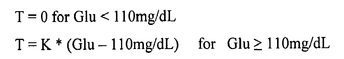
- Glu is a glucose assessment (mg/dL); and
- K is a proportionality constant
- It is envisioned that a user of a device according to the present invention (e.g.,
device 100 ofFIG. 1 ) incorporating the mode of operation described in relation toFIG. 4 would learn to perceive differences in vibration pulse duration correlated to changes in their blood glucose concentration. Over time, the user would relate the sensations to their blood glucose concentration. -
FIG. 5 is a table listing six glucose concentration ranges and corresponding user-perceived sensations (i.e., user-perceived sensations consisting of a predetermined number of vibration pulses, each pulse being of an identical predetermined duration) as can be employed in embodiments of the present invention. If a user is immersed in physical activity, it may be difficult for the user to perceive and identify the amplitude or duration of a single vibratory pulse. Therefore, a particularly beneficial proportionality between a user-perceived sensation (such as a user-perceived vibratory sensation) and the user's bodily fluid analyte concentration can be achieved using a step-wise proportionality based on the number of vibratory pulses (each pulse being of an identical duration) as tabulated inFIG. 5 . - Moreover, to garner a user's attention, a pre-alert user-perceived sensation can be generated by devices according to embodiments of the present invention prior to generating the user-perceived sensation. The pre-alert user-perceived sensation can be the identical to or different than the user-perceived sensation itself. For example, a pre-alert user-perceived vibratory sensation of relatively long duration can be employed to make the user generally aware of the sensation, thereby making subsequent user-perceived sensations more easily recognized (for example, more easily counted).
-
FIG. 6 is a graph of vibration amplitude (in units of volts) as a function of time depicting two user-perceived sensations, each consisting of a series of pulses that serve to illustrate the use of a step-wise proportionality such as that ofFIG. 5 . Referring toFIGs. 5 and6 , a first series S1 of three vibration pulses (i.e., pulses P1(400), P2(400) and P3(400)) is depicted. A predetermined time interval I (for example, 2 minutes) separatesfirst series S 1 from second series S2 of three vibration pulses P1'(450), P2'(450), P3'(450), and P4'(450). In other words, in the embodiment ofFIGs. 5 and6 , a user-perceived sensation consisting of a series of vibratory pulses is generated at a predetermined time interval. - In
FIG. 6 , each pulse within a given series has a duration of time "t" (for example, 0.2 seconds), an amplitude of "V," and is separated from the next pulse within the series by a duration "R" (for example, 0.3 seconds). First series S1 corresponds to a glucose concentration of 400 mg/dL and, therefore, has a pulse count of three. Second series S2 corresponds to a glucose concentration of 450 mg/dL and, therefore, has a pulse count of four. - Once apprised of the present disclosure, one skilled in the art will be aware of other methods of achieving proportionality. For example, proportionality can be achieved using vibration frequency or changing the time elapsed between pulses of vibration.
- It should be noted that since devices according to embodiments of the present invention generate a user-perceived sensation at predetermined time intervals, the devices beneficially enable a user to perceive not only their bodily fluid analyte concentration at a single moment in time but to also perceive trends in their bodily fluid analyte concentration. The user can then associate the concentration and concentration trends with, for example, their physical state (e.g., whether they are tired, dizzy or experiencing a headache) and/or recent activities (e.g., meals eaten or activity undertaken). The devices, therefore, serve to train a user in the recognition of their bodily fluid analyte concentration and concentration trends. These functions and benefits are distinguished over devices that include conventional alarms configured to notify a user when dangerous bodily fluid concentrations occur. Such conventional alarms are not generated at predetermined time intervals but only when the dangerous bodily fluid concentrations occur. Such conventional alarms are also not proportional to the bodily fluid analyte concentration.
-
FIG. 7 is a simplified illustration ofdevice 700 according to another exemplary embodiment of the present invention employed on an arm of auser U. Device 700 is essentiallydevice 100 ofFIG. 1 configured as an armband mounted device.Device 700 includes ananalyte monitoring module 102, acontrol module 104 and asensation generation module 106 integrated withinarmband 702.Device 700 is configured for removable attachment to a user's arm using any suitable technique. -
FIG. 8 is a simplified illustration ofdevice 800 according to another exemplary embodiment of the present invention employed on a finger of a user'shand H. Device 800 is essentiallydevice 100 ofFIG. 1 configured as a finger ring.Device 800, therefore, includes ananalyte monitoring module 102, acontrol module 104 and asensation generation module 106 integrated withinring 802. Such a ring-shaped device can be worn on user's finger without attracting undue attention. - Since the user-perceived sensations generated by devices according to embodiments of the present invention are non-visual in nature, the user need not interrupt their activities to read bodily fluid analyte concentration values. Devices according to the present invention that employ tactile user-perceived sensations (such as vibration) are also beneficial in that they provide training in a discrete manner that does not attract the attention of bystanders.
- It is envisioned that over time a user will come to associate the user-perceived sensations (which are proportional to their bodily fluid analyte concentration) with their physical state at the moment the user-perceived sensation is perceived and/or with recent activities such as the intake of various foods, stressful events or exercise. For example, high bodily fluid analyte concentrations could be associated with the physical state of a mild headache while low bodily fluid analyte concentration could be associated with the physical state of tiredness. Thereafter, even in the absence of the device, a person who had been trained by using the device could assess their bodily fluid analyte concentration based on perception of their physical state and take appropriate action (e.g., food consumption or exercise) to control the bodily fluid analyte concentration.
- Devices according to embodiments of the present invention train a user to associate changes in their bodily fluid analyte concentration (e.g., glucose) with natural bodily sensations such as dizziness, tiredness, and headaches and/or natural activities (e.g., the eating of various foods and exercise). The devices, therefore, serve as a training aid by teaching a user over time how to assess their bodily fluid analyte concentration based on their physical state and/or activities and to beneficially modify such bodily fluid analyte concentration by modifications to lifestyle, such as food intake and exercise.
-
FIG. 9 is a flow diagram depicting stages inmethod 900 for training a user in recognition of the user's bodily fluid analyte concentration and concentration trends according to an exemplary embodiment of the present invention.Method 900 includes monitoring a user's bodily fluid analyte concentration (for example, a user's whole blood glucose concentration) with an analyte monitoring module of a device for training a user in recognition of the user's bodily fluid analyte concentration, as set forth instep 910. - At
step 920,method 900 also includes generating, using a generation module of the device, a user-perceived sensation (e.g., a user-perceived vibratory sensation) at predetermined time intervals that is proportional the user's bodily fluid analyte concentration in a predetermined manner. - Once apprised of the present disclosure, one skilled in the art will recognize that
method 900 can be practiced using devices according to embodiments of the present invention. Therefore, any of the functional characteristics and benefits described with respect to devices according to the present invention can be incorporated intomethod 900. - It should be understood that various alternatives to the embodiments of the invention described herein may be employed in practicing the invention. It is intended that the following claims define the scope of the invention and that methods and structures within the scope of these claims and their equivalents be covered thereby.
Claims (15)
- A method of training a user in recognition of the user's bodily fluid analyte concentration and concentration trends comprising:monitoring a user's bodily fluid analyte concentration with an analyte monitoring module of a device for training a user in recognition of the user's bodily fluid analyte concentration; andgenerating a user-perceived sensation, at predetermined time interval, that is proportional the user's bodily fluid analyte concentration in a predetermined manner using a sensation generation module of the device.
- The method of claim 1 wherein the generating step generates a user-perceived vibratory sensation.
- The method of claim 2 wherein a duration of the user-perceived vibratory sensation is proportional to the user's bodily fluid analyte concentration in predetermined proportional manner.
- The method of claim 2 wherein an amplitude of the user-perceived vibratory sensation is proportional to the user's bodily fluid analyte concentration in predetermined proportional manner.
- The method of claim 2 wherein the user-perceived vibratory sensation is proportional to the user's bodily fluid analyte concentration in predetermined proportional manner based on a count of user-perceived vibratory sensations.
- The method of claim 1 wherein the user-perceived sensation is proportional to the user's bodily fluid analyte concentration in a predetermined step-wise manner.
- The method of claim 1 wherein the monitoring step monitors a user's bodily fluid glucose concentration.
- The method of claim 1 the generating step also generates a pre-alert user-perceived sensation prior to generating the user-perceived sensation.
- A device comprising:means for monitoring a user's bodily fluid analyte concentration for training a user in recognition of the user's bodily fluid analyte concentration; andmeans for generating a user-perceived sensation, at predetermined time interval, that is proportional to the user's bodily fluid analyte concentration in a predetermined manner.
- The device of claim 9 wherein the means of generating a user-perceived sensation generates a user-perceived vibratory sensation.
- The device of claim 10 wherein a duration of the user-perceived vibratory sensation, or wherein an amplitude of the user-perceived vibratory sensation, is proportional to the user's bodily fluid analyte concentration in predetermined proportional manner.
- The device of claim 10 wherein the user-perceived vibratory sensation is proportional to the user's bodily fluid analyte concentration in predetermined proportional manner based on a count of user-perceived vibratory sensations.
- The device of claim 9 wherein the user-perceived sensation is proportional to the user's bodily fluid analyte concentration in a predetermined step-wise manner.
- The device of claim 9 wherein the means of generating a user-perceived sensation generates a pre-alert user-perceived sensation prior to generating the user-perceived sensation.
- The device of claim 9, wherein the means of monitoring the user's bodily fluid anaylte concentration determines whether the analyte concentration is above a threshold value, and wherein if the analyte concentration is less than or equal to a threshold value, no user-perceived sensation will be generated.
Applications Claiming Priority (1)
| Application Number | Priority Date | Filing Date | Title |
|---|---|---|---|
| US11/768,114 US20080319284A1 (en) | 2007-06-25 | 2007-06-25 | Method for training a user in recognition of the user's bodily fluid analyte concentration and concentration trends via user-perceived sensations |
Publications (2)
| Publication Number | Publication Date |
|---|---|
| EP2012292A2 true EP2012292A2 (en) | 2009-01-07 |
| EP2012292A3 EP2012292A3 (en) | 2009-08-12 |
Family
ID=39735536
Family Applications (1)
| Application Number | Title | Priority Date | Filing Date |
|---|---|---|---|
| EP08252166A Withdrawn EP2012292A3 (en) | 2007-06-25 | 2008-06-24 | Method for training a user in recognition of the user's bodily fluid analyte concentration and concentration trends via user-perceived sensations |
Country Status (5)
| Country | Link |
|---|---|
| US (1) | US20080319284A1 (en) |
| EP (1) | EP2012292A3 (en) |
| JP (1) | JP2009106725A (en) |
| CN (1) | CN101334400A (en) |
| CA (1) | CA2635873A1 (en) |
Families Citing this family (49)
| Publication number | Priority date | Publication date | Assignee | Title |
|---|---|---|---|---|
| US6391005B1 (en) | 1998-03-30 | 2002-05-21 | Agilent Technologies, Inc. | Apparatus and method for penetration with shaft having a sensor for sensing penetration depth |
| US8641644B2 (en) | 2000-11-21 | 2014-02-04 | Sanofi-Aventis Deutschland Gmbh | Blood testing apparatus having a rotatable cartridge with multiple lancing elements and testing means |
| US8337419B2 (en) | 2002-04-19 | 2012-12-25 | Sanofi-Aventis Deutschland Gmbh | Tissue penetration device |
| CA2448902C (en) | 2001-06-12 | 2010-09-07 | Pelikan Technologies, Inc. | Self optimizing lancing device with adaptation means to temporal variations in cutaneous properties |
| US9226699B2 (en) | 2002-04-19 | 2016-01-05 | Sanofi-Aventis Deutschland Gmbh | Body fluid sampling module with a continuous compression tissue interface surface |
| US7033371B2 (en) | 2001-06-12 | 2006-04-25 | Pelikan Technologies, Inc. | Electric lancet actuator |
| US7749174B2 (en) | 2001-06-12 | 2010-07-06 | Pelikan Technologies, Inc. | Method and apparatus for lancet launching device intergrated onto a blood-sampling cartridge |
| US7041068B2 (en) | 2001-06-12 | 2006-05-09 | Pelikan Technologies, Inc. | Sampling module device and method |
| US7981056B2 (en) | 2002-04-19 | 2011-07-19 | Pelikan Technologies, Inc. | Methods and apparatus for lancet actuation |
| US9427532B2 (en) | 2001-06-12 | 2016-08-30 | Sanofi-Aventis Deutschland Gmbh | Tissue penetration device |
| US7344507B2 (en) | 2002-04-19 | 2008-03-18 | Pelikan Technologies, Inc. | Method and apparatus for lancet actuation |
| US9795747B2 (en) | 2010-06-02 | 2017-10-24 | Sanofi-Aventis Deutschland Gmbh | Methods and apparatus for lancet actuation |
| US9248267B2 (en) | 2002-04-19 | 2016-02-02 | Sanofi-Aventis Deustchland Gmbh | Tissue penetration device |
| US7909778B2 (en) | 2002-04-19 | 2011-03-22 | Pelikan Technologies, Inc. | Method and apparatus for penetrating tissue |
| US7226461B2 (en) | 2002-04-19 | 2007-06-05 | Pelikan Technologies, Inc. | Method and apparatus for a multi-use body fluid sampling device with sterility barrier release |
| US7892183B2 (en) | 2002-04-19 | 2011-02-22 | Pelikan Technologies, Inc. | Method and apparatus for body fluid sampling and analyte sensing |
| US8360992B2 (en) | 2002-04-19 | 2013-01-29 | Sanofi-Aventis Deutschland Gmbh | Method and apparatus for penetrating tissue |
| US7229458B2 (en) | 2002-04-19 | 2007-06-12 | Pelikan Technologies, Inc. | Method and apparatus for penetrating tissue |
| US8784335B2 (en) | 2002-04-19 | 2014-07-22 | Sanofi-Aventis Deutschland Gmbh | Body fluid sampling device with a capacitive sensor |
| US7674232B2 (en) | 2002-04-19 | 2010-03-09 | Pelikan Technologies, Inc. | Method and apparatus for penetrating tissue |
| US7547287B2 (en) | 2002-04-19 | 2009-06-16 | Pelikan Technologies, Inc. | Method and apparatus for penetrating tissue |
| US8221334B2 (en) | 2002-04-19 | 2012-07-17 | Sanofi-Aventis Deutschland Gmbh | Method and apparatus for penetrating tissue |
| US8579831B2 (en) | 2002-04-19 | 2013-11-12 | Sanofi-Aventis Deutschland Gmbh | Method and apparatus for penetrating tissue |
| US7232451B2 (en) | 2002-04-19 | 2007-06-19 | Pelikan Technologies, Inc. | Method and apparatus for penetrating tissue |
| US7976476B2 (en) | 2002-04-19 | 2011-07-12 | Pelikan Technologies, Inc. | Device and method for variable speed lancet |
| US7297122B2 (en) | 2002-04-19 | 2007-11-20 | Pelikan Technologies, Inc. | Method and apparatus for penetrating tissue |
| US8702624B2 (en) | 2006-09-29 | 2014-04-22 | Sanofi-Aventis Deutschland Gmbh | Analyte measurement device with a single shot actuator |
| US8267870B2 (en) | 2002-04-19 | 2012-09-18 | Sanofi-Aventis Deutschland Gmbh | Method and apparatus for body fluid sampling with hybrid actuation |
| US7491178B2 (en) | 2002-04-19 | 2009-02-17 | Pelikan Technologies, Inc. | Method and apparatus for penetrating tissue |
| US8372016B2 (en) | 2002-04-19 | 2013-02-12 | Sanofi-Aventis Deutschland Gmbh | Method and apparatus for body fluid sampling and analyte sensing |
| US7331931B2 (en) | 2002-04-19 | 2008-02-19 | Pelikan Technologies, Inc. | Method and apparatus for penetrating tissue |
| US9314194B2 (en) | 2002-04-19 | 2016-04-19 | Sanofi-Aventis Deutschland Gmbh | Tissue penetration device |
| US7901362B2 (en) | 2002-04-19 | 2011-03-08 | Pelikan Technologies, Inc. | Method and apparatus for penetrating tissue |
| US9795334B2 (en) | 2002-04-19 | 2017-10-24 | Sanofi-Aventis Deutschland Gmbh | Method and apparatus for penetrating tissue |
| US8574895B2 (en) | 2002-12-30 | 2013-11-05 | Sanofi-Aventis Deutschland Gmbh | Method and apparatus using optical techniques to measure analyte levels |
| ES2347248T3 (en) | 2003-05-30 | 2010-10-27 | Pelikan Technologies Inc. | PROCEDURE AND APPLIANCE FOR FLUID INJECTION. |
| WO2004107964A2 (en) | 2003-06-06 | 2004-12-16 | Pelikan Technologies, Inc. | Blood harvesting device with electronic control |
| WO2006001797A1 (en) | 2004-06-14 | 2006-01-05 | Pelikan Technologies, Inc. | Low pain penetrating |
| WO2005033659A2 (en) | 2003-09-29 | 2005-04-14 | Pelikan Technologies, Inc. | Method and apparatus for an improved sample capture device |
| US9351680B2 (en) | 2003-10-14 | 2016-05-31 | Sanofi-Aventis Deutschland Gmbh | Method and apparatus for a variable user interface |
| EP1706026B1 (en) | 2003-12-31 | 2017-03-01 | Sanofi-Aventis Deutschland GmbH | Method and apparatus for improving fluidic flow and sample capture |
| US7822454B1 (en) | 2005-01-03 | 2010-10-26 | Pelikan Technologies, Inc. | Fluid sampling device with improved analyte detecting member configuration |
| US8828203B2 (en) | 2004-05-20 | 2014-09-09 | Sanofi-Aventis Deutschland Gmbh | Printable hydrogels for biosensors |
| US9820684B2 (en) | 2004-06-03 | 2017-11-21 | Sanofi-Aventis Deutschland Gmbh | Method and apparatus for a fluid sampling device |
| US9775553B2 (en) | 2004-06-03 | 2017-10-03 | Sanofi-Aventis Deutschland Gmbh | Method and apparatus for a fluid sampling device |
| US8652831B2 (en) | 2004-12-30 | 2014-02-18 | Sanofi-Aventis Deutschland Gmbh | Method and apparatus for analyte measurement test time |
| WO2009126900A1 (en) | 2008-04-11 | 2009-10-15 | Pelikan Technologies, Inc. | Method and apparatus for analyte detecting device |
| US9375169B2 (en) | 2009-01-30 | 2016-06-28 | Sanofi-Aventis Deutschland Gmbh | Cam drive for managing disposable penetrating member actions with a single motor and motor and control system |
| US8965476B2 (en) | 2010-04-16 | 2015-02-24 | Sanofi-Aventis Deutschland Gmbh | Tissue penetration device |
Citations (5)
| Publication number | Priority date | Publication date | Assignee | Title |
|---|---|---|---|---|
| US5140985A (en) | 1989-12-11 | 1992-08-25 | Schroeder Jon M | Noninvasive blood glucose measuring device |
| US5497772A (en) | 1993-11-19 | 1996-03-12 | Alfred E. Mann Foundation For Scientific Research | Glucose monitoring system |
| US6175752B1 (en) | 1998-04-30 | 2001-01-16 | Therasense, Inc. | Analyte monitoring device and methods of use |
| US7110803B2 (en) | 1997-03-04 | 2006-09-19 | Dexcom, Inc. | Device and method for determining analyte levels |
| US7150975B2 (en) | 2002-08-19 | 2006-12-19 | Animas Technologies, Llc | Hydrogel composition for measuring glucose flux |
Family Cites Families (13)
| Publication number | Priority date | Publication date | Assignee | Title |
|---|---|---|---|---|
| US4819656A (en) * | 1985-04-30 | 1989-04-11 | Donald Spector | Biofeedback therapy system |
| DE3812584A1 (en) * | 1988-04-13 | 1989-10-26 | Mic Medical Instr Corp | DEVICE FOR BIOFEEDBACK CONTROL OF BODY FUNCTIONS |
| US5190041A (en) * | 1989-08-11 | 1993-03-02 | Palti Yoram Prof | System for monitoring and controlling blood glucose |
| US5791344A (en) * | 1993-11-19 | 1998-08-11 | Alfred E. Mann Foundation For Scientific Research | Patient monitoring system |
| JP2004121864A (en) * | 1995-09-13 | 2004-04-22 | Seiko Epson Corp | Health condition managing apparatus |
| US6328699B1 (en) * | 2000-01-11 | 2001-12-11 | Cedars-Sinai Medical Center | Permanently implantable system and method for detecting, diagnosing and treating congestive heart failure |
| US6553244B2 (en) * | 2000-08-18 | 2003-04-22 | Cygnus, Inc. | Analyte monitoring device alarm augmentation system |
| JP3768435B2 (en) * | 2001-05-16 | 2006-04-19 | 東芝テック株式会社 | Blood glucose level measuring device |
| US7399277B2 (en) * | 2001-12-27 | 2008-07-15 | Medtronic Minimed, Inc. | System for monitoring physiological characteristics |
| US20030153832A1 (en) * | 2002-01-22 | 2003-08-14 | Jona Zumeris | System and method for smart monitoring within a body |
| JP2006051317A (en) * | 2004-08-13 | 2006-02-23 | Research Institute Of Human Engineering For Quality Life | Emotion transmission system |
| JP2007000188A (en) * | 2005-06-21 | 2007-01-11 | Toshiba Corp | Medical support apparatus |
| JP4744976B2 (en) * | 2005-08-09 | 2011-08-10 | 株式会社東芝 | Biological information measuring apparatus and method |
-
2007
- 2007-06-25 US US11/768,114 patent/US20080319284A1/en not_active Abandoned
-
2008
- 2008-06-12 JP JP2008153670A patent/JP2009106725A/en active Pending
- 2008-06-24 EP EP08252166A patent/EP2012292A3/en not_active Withdrawn
- 2008-06-25 CA CA002635873A patent/CA2635873A1/en not_active Abandoned
- 2008-06-25 CN CNA2008101446067A patent/CN101334400A/en active Pending
Patent Citations (5)
| Publication number | Priority date | Publication date | Assignee | Title |
|---|---|---|---|---|
| US5140985A (en) | 1989-12-11 | 1992-08-25 | Schroeder Jon M | Noninvasive blood glucose measuring device |
| US5497772A (en) | 1993-11-19 | 1996-03-12 | Alfred E. Mann Foundation For Scientific Research | Glucose monitoring system |
| US7110803B2 (en) | 1997-03-04 | 2006-09-19 | Dexcom, Inc. | Device and method for determining analyte levels |
| US6175752B1 (en) | 1998-04-30 | 2001-01-16 | Therasense, Inc. | Analyte monitoring device and methods of use |
| US7150975B2 (en) | 2002-08-19 | 2006-12-19 | Animas Technologies, Llc | Hydrogel composition for measuring glucose flux |
Also Published As
| Publication number | Publication date |
|---|---|
| CA2635873A1 (en) | 2008-12-25 |
| US20080319284A1 (en) | 2008-12-25 |
| CN101334400A (en) | 2008-12-31 |
| JP2009106725A (en) | 2009-05-21 |
| EP2012292A3 (en) | 2009-08-12 |
Similar Documents
| Publication | Publication Date | Title |
|---|---|---|
| EP2012292A2 (en) | Method for training a user in recognition of the user's bodily fluid analyte concentration and concentration trends via user-perceived sensations | |
| US20080318193A1 (en) | Medical training aid device for training a user in recognition of the user's bodily fluid analyte concentration and concentration trends via user-perceived sensations | |
| US11116933B2 (en) | Systems, methods and devices for paired plasticity | |
| Galatzer et al. | Crisis intervention program in newly diagnosed diabetic children | |
| US8425427B2 (en) | Pulse wave detection device, device control device, and pulse wave detection method | |
| US8269634B2 (en) | Systems and methods of alarm validation and backup in implanted medical devices | |
| US20230277801A1 (en) | Apparatus for administering bilateral tactile stimulation to a human subject | |
| WO2005121785A3 (en) | System for monitoring physiological characteristics according to the user biological state | |
| US20050137503A1 (en) | Massage machine and physiological quantity measuring circuit for use in the machine | |
| US20030030544A1 (en) | Individual discreet prompting device with remote | |
| US20100286653A1 (en) | Remote control device for use with insulin infusion systems | |
| CN2891967Y (en) | Driver's fatigue driving monitoring and feedback stimulating instrument | |
| CN103271735A (en) | Heart beat rate detecting system and application thereof | |
| US5424719A (en) | Consumption control | |
| JP4844523B2 (en) | Mental training system | |
| JP2005052461A (en) | Electric current applying device for organism | |
| WO2022163354A1 (en) | Information processing method, terminal device, and program | |
| JPH1071137A (en) | Device and method for displaying degree of stress | |
| US20170181710A9 (en) | Method of detecting and predicting neurocardiogenic syncope | |
| Graham et al. | Maximal and Submaximal Intensity Isometric Knee Extensions Induce an Underestimation of Time Estimates with Both Younger And Older Adults: A Randomized Crossover Trial | |
| JPS62253032A (en) | Relax degree detector | |
| WO2014093358A1 (en) | Time management device | |
| WO1998055077A2 (en) | Method and apparatus for ridding the human body of pathogens | |
| CN108055607A (en) | Intelligent sleep bidirectional monitoring earphone | |
| JP2017047099A (en) | Blood flow measurement device and blood flow measurement method |
Legal Events
| Date | Code | Title | Description |
|---|---|---|---|
| PUAI | Public reference made under article 153(3) epc to a published international application that has entered the european phase |
Free format text: ORIGINAL CODE: 0009012 |
|
| AK | Designated contracting states |
Kind code of ref document: A2 Designated state(s): AT BE BG CH CY CZ DE DK EE ES FI FR GB GR HR HU IE IS IT LI LT LU LV MC MT NL NO PL PT RO SE SI SK TR |
|
| AX | Request for extension of the european patent |
Extension state: AL BA MK RS |
|
| PUAL | Search report despatched |
Free format text: ORIGINAL CODE: 0009013 |
|
| AK | Designated contracting states |
Kind code of ref document: A3 Designated state(s): AT BE BG CH CY CZ DE DK EE ES FI FR GB GR HR HU IE IS IT LI LT LU LV MC MT NL NO PL PT RO SE SI SK TR |
|
| AX | Request for extension of the european patent |
Extension state: AL BA MK RS |
|
| REG | Reference to a national code |
Ref country code: HK Ref legal event code: DE Ref document number: 1127970 Country of ref document: HK |
|
| 17P | Request for examination filed |
Effective date: 20100115 |
|
| 17Q | First examination report despatched |
Effective date: 20100209 |
|
| AKX | Designation fees paid |
Designated state(s): AT BE BG CH CY CZ DE DK EE ES FI FR GB GR HR HU IE IS IT LI LT LU LV MC MT NL NO PL PT RO SE SI SK TR |
|
| STAA | Information on the status of an ep patent application or granted ep patent |
Free format text: STATUS: THE APPLICATION IS DEEMED TO BE WITHDRAWN |
|
| 18D | Application deemed to be withdrawn |
Effective date: 20100820 |
|
| REG | Reference to a national code |
Ref country code: HK Ref legal event code: WD Ref document number: 1127970 Country of ref document: HK |