EP2012533A1 - Image processing device and image processing method - Google Patents
Image processing device and image processing method Download PDFInfo
- Publication number
- EP2012533A1 EP2012533A1 EP07742717A EP07742717A EP2012533A1 EP 2012533 A1 EP2012533 A1 EP 2012533A1 EP 07742717 A EP07742717 A EP 07742717A EP 07742717 A EP07742717 A EP 07742717A EP 2012533 A1 EP2012533 A1 EP 2012533A1
- Authority
- EP
- European Patent Office
- Prior art keywords
- display
- video data
- image processing
- processing apparatus
- parameters
- Prior art date
- Legal status (The legal status is an assumption and is not a legal conclusion. Google has not performed a legal analysis and makes no representation as to the accuracy of the status listed.)
- Withdrawn
Links
- 238000012545 processing Methods 0.000 title claims description 377
- 238000003672 processing method Methods 0.000 title claims description 6
- 230000033001 locomotion Effects 0.000 claims description 118
- 230000008859 change Effects 0.000 claims description 57
- 230000005540 biological transmission Effects 0.000 claims description 4
- 238000002834 transmittance Methods 0.000 claims 1
- 238000004364 calculation method Methods 0.000 description 58
- 238000001514 detection method Methods 0.000 description 55
- 238000000034 method Methods 0.000 description 39
- 102220279311 rs1555054249 Human genes 0.000 description 27
- 238000009825 accumulation Methods 0.000 description 22
- 239000006185 dispersion Substances 0.000 description 21
- 239000013598 vector Substances 0.000 description 21
- 101100156776 Oryza sativa subsp. japonica WOX1 gene Proteins 0.000 description 12
- 101150075910 SRT1 gene Proteins 0.000 description 12
- 238000004458 analytical method Methods 0.000 description 10
- 238000000605 extraction Methods 0.000 description 10
- 238000012546 transfer Methods 0.000 description 10
- 238000007667 floating Methods 0.000 description 9
- 238000007726 management method Methods 0.000 description 9
- 230000006870 function Effects 0.000 description 8
- 238000010586 diagram Methods 0.000 description 7
- 230000009471 action Effects 0.000 description 5
- 230000000694 effects Effects 0.000 description 5
- 230000008707 rearrangement Effects 0.000 description 5
- 238000004891 communication Methods 0.000 description 4
- 239000000284 extract Substances 0.000 description 4
- 101000642536 Apis mellifera Venom serine protease 34 Proteins 0.000 description 3
- 102100031798 Protein eva-1 homolog A Human genes 0.000 description 3
- 102100021916 Sperm-associated antigen 1 Human genes 0.000 description 3
- 102100040791 Zona pellucida-binding protein 1 Human genes 0.000 description 3
- 238000006243 chemical reaction Methods 0.000 description 3
- 230000004048 modification Effects 0.000 description 3
- 238000012986 modification Methods 0.000 description 3
- 230000003287 optical effect Effects 0.000 description 3
- 230000009467 reduction Effects 0.000 description 3
- 102100022907 Acrosin-binding protein Human genes 0.000 description 2
- 238000013459 approach Methods 0.000 description 2
- 230000008901 benefit Effects 0.000 description 2
- 230000003247 decreasing effect Effects 0.000 description 2
- 238000005516 engineering process Methods 0.000 description 2
- 230000008569 process Effects 0.000 description 2
- 230000005236 sound signal Effects 0.000 description 2
- 230000000007 visual effect Effects 0.000 description 2
- 238000003491 array Methods 0.000 description 1
- 230000004397 blinking Effects 0.000 description 1
- 238000012790 confirmation Methods 0.000 description 1
- 238000012217 deletion Methods 0.000 description 1
- 230000037430 deletion Effects 0.000 description 1
- 238000007599 discharging Methods 0.000 description 1
- 230000002708 enhancing effect Effects 0.000 description 1
- 230000001771 impaired effect Effects 0.000 description 1
- 230000009191 jumping Effects 0.000 description 1
- 230000006855 networking Effects 0.000 description 1
- 230000002093 peripheral effect Effects 0.000 description 1
- 238000009877 rendering Methods 0.000 description 1
- 239000004065 semiconductor Substances 0.000 description 1
- 238000004904 shortening Methods 0.000 description 1
- 238000004088 simulation Methods 0.000 description 1
Images


Classifications
-
- H—ELECTRICITY
- H04—ELECTRIC COMMUNICATION TECHNIQUE
- H04N—PICTORIAL COMMUNICATION, e.g. TELEVISION
- H04N21/00—Selective content distribution, e.g. interactive television or video on demand [VOD]
- H04N21/40—Client devices specifically adapted for the reception of or interaction with content, e.g. set-top-box [STB]; Operations thereof
- H04N21/43—Processing of content or additional data, e.g. demultiplexing additional data from a digital video stream; Elementary client operations, e.g. monitoring of home network or synchronising decoder's clock; Client middleware
- H04N21/431—Generation of visual interfaces for content selection or interaction; Content or additional data rendering
-
- H—ELECTRICITY
- H04—ELECTRIC COMMUNICATION TECHNIQUE
- H04N—PICTORIAL COMMUNICATION, e.g. TELEVISION
- H04N21/00—Selective content distribution, e.g. interactive television or video on demand [VOD]
- H04N21/80—Generation or processing of content or additional data by content creator independently of the distribution process; Content per se
- H04N21/83—Generation or processing of protective or descriptive data associated with content; Content structuring
- H04N21/84—Generation or processing of descriptive data, e.g. content descriptors
-
- G—PHYSICS
- G06—COMPUTING; CALCULATING OR COUNTING
- G06F—ELECTRIC DIGITAL DATA PROCESSING
- G06F16/00—Information retrieval; Database structures therefor; File system structures therefor
- G06F16/70—Information retrieval; Database structures therefor; File system structures therefor of video data
- G06F16/74—Browsing; Visualisation therefor
- G06F16/743—Browsing; Visualisation therefor a collection of video files or sequences
-
- G—PHYSICS
- G06—COMPUTING; CALCULATING OR COUNTING
- G06F—ELECTRIC DIGITAL DATA PROCESSING
- G06F16/00—Information retrieval; Database structures therefor; File system structures therefor
- G06F16/70—Information retrieval; Database structures therefor; File system structures therefor of video data
- G06F16/78—Retrieval characterised by using metadata, e.g. metadata not derived from the content or metadata generated manually
- G06F16/783—Retrieval characterised by using metadata, e.g. metadata not derived from the content or metadata generated manually using metadata automatically derived from the content
- G06F16/7834—Retrieval characterised by using metadata, e.g. metadata not derived from the content or metadata generated manually using metadata automatically derived from the content using audio features
-
- G—PHYSICS
- G06—COMPUTING; CALCULATING OR COUNTING
- G06F—ELECTRIC DIGITAL DATA PROCESSING
- G06F16/00—Information retrieval; Database structures therefor; File system structures therefor
- G06F16/70—Information retrieval; Database structures therefor; File system structures therefor of video data
- G06F16/78—Retrieval characterised by using metadata, e.g. metadata not derived from the content or metadata generated manually
- G06F16/783—Retrieval characterised by using metadata, e.g. metadata not derived from the content or metadata generated manually using metadata automatically derived from the content
- G06F16/7847—Retrieval characterised by using metadata, e.g. metadata not derived from the content or metadata generated manually using metadata automatically derived from the content using low-level visual features of the video content
- G06F16/785—Retrieval characterised by using metadata, e.g. metadata not derived from the content or metadata generated manually using metadata automatically derived from the content using low-level visual features of the video content using colour or luminescence
-
- G—PHYSICS
- G06—COMPUTING; CALCULATING OR COUNTING
- G06F—ELECTRIC DIGITAL DATA PROCESSING
- G06F16/00—Information retrieval; Database structures therefor; File system structures therefor
- G06F16/70—Information retrieval; Database structures therefor; File system structures therefor of video data
- G06F16/78—Retrieval characterised by using metadata, e.g. metadata not derived from the content or metadata generated manually
- G06F16/783—Retrieval characterised by using metadata, e.g. metadata not derived from the content or metadata generated manually using metadata automatically derived from the content
- G06F16/7847—Retrieval characterised by using metadata, e.g. metadata not derived from the content or metadata generated manually using metadata automatically derived from the content using low-level visual features of the video content
- G06F16/786—Retrieval characterised by using metadata, e.g. metadata not derived from the content or metadata generated manually using metadata automatically derived from the content using low-level visual features of the video content using motion, e.g. object motion or camera motion
-
- G—PHYSICS
- G06—COMPUTING; CALCULATING OR COUNTING
- G06F—ELECTRIC DIGITAL DATA PROCESSING
- G06F16/00—Information retrieval; Database structures therefor; File system structures therefor
- G06F16/70—Information retrieval; Database structures therefor; File system structures therefor of video data
- G06F16/78—Retrieval characterised by using metadata, e.g. metadata not derived from the content or metadata generated manually
- G06F16/783—Retrieval characterised by using metadata, e.g. metadata not derived from the content or metadata generated manually using metadata automatically derived from the content
- G06F16/7847—Retrieval characterised by using metadata, e.g. metadata not derived from the content or metadata generated manually using metadata automatically derived from the content using low-level visual features of the video content
- G06F16/7864—Retrieval characterised by using metadata, e.g. metadata not derived from the content or metadata generated manually using metadata automatically derived from the content using low-level visual features of the video content using domain-transform features, e.g. DCT or wavelet transform coefficients
-
- G—PHYSICS
- G06—COMPUTING; CALCULATING OR COUNTING
- G06F—ELECTRIC DIGITAL DATA PROCESSING
- G06F3/00—Input arrangements for transferring data to be processed into a form capable of being handled by the computer; Output arrangements for transferring data from processing unit to output unit, e.g. interface arrangements
- G06F3/01—Input arrangements or combined input and output arrangements for interaction between user and computer
- G06F3/048—Interaction techniques based on graphical user interfaces [GUI]
- G06F3/0481—Interaction techniques based on graphical user interfaces [GUI] based on specific properties of the displayed interaction object or a metaphor-based environment, e.g. interaction with desktop elements like windows or icons, or assisted by a cursor's changing behaviour or appearance
-
- G—PHYSICS
- G06—COMPUTING; CALCULATING OR COUNTING
- G06F—ELECTRIC DIGITAL DATA PROCESSING
- G06F3/00—Input arrangements for transferring data to be processed into a form capable of being handled by the computer; Output arrangements for transferring data from processing unit to output unit, e.g. interface arrangements
- G06F3/01—Input arrangements or combined input and output arrangements for interaction between user and computer
- G06F3/048—Interaction techniques based on graphical user interfaces [GUI]
- G06F3/0484—Interaction techniques based on graphical user interfaces [GUI] for the control of specific functions or operations, e.g. selecting or manipulating an object, an image or a displayed text element, setting a parameter value or selecting a range
- G06F3/04845—Interaction techniques based on graphical user interfaces [GUI] for the control of specific functions or operations, e.g. selecting or manipulating an object, an image or a displayed text element, setting a parameter value or selecting a range for image manipulation, e.g. dragging, rotation, expansion or change of colour
-
- G—PHYSICS
- G11—INFORMATION STORAGE
- G11B—INFORMATION STORAGE BASED ON RELATIVE MOVEMENT BETWEEN RECORD CARRIER AND TRANSDUCER
- G11B27/00—Editing; Indexing; Addressing; Timing or synchronising; Monitoring; Measuring tape travel
- G11B27/02—Editing, e.g. varying the order of information signals recorded on, or reproduced from, record carriers
- G11B27/031—Electronic editing of digitised analogue information signals, e.g. audio or video signals
- G11B27/032—Electronic editing of digitised analogue information signals, e.g. audio or video signals on tapes
-
- G—PHYSICS
- G11—INFORMATION STORAGE
- G11B—INFORMATION STORAGE BASED ON RELATIVE MOVEMENT BETWEEN RECORD CARRIER AND TRANSDUCER
- G11B27/00—Editing; Indexing; Addressing; Timing or synchronising; Monitoring; Measuring tape travel
- G11B27/02—Editing, e.g. varying the order of information signals recorded on, or reproduced from, record carriers
- G11B27/031—Electronic editing of digitised analogue information signals, e.g. audio or video signals
- G11B27/034—Electronic editing of digitised analogue information signals, e.g. audio or video signals on discs
-
- G—PHYSICS
- G11—INFORMATION STORAGE
- G11B—INFORMATION STORAGE BASED ON RELATIVE MOVEMENT BETWEEN RECORD CARRIER AND TRANSDUCER
- G11B27/00—Editing; Indexing; Addressing; Timing or synchronising; Monitoring; Measuring tape travel
- G11B27/10—Indexing; Addressing; Timing or synchronising; Measuring tape travel
- G11B27/19—Indexing; Addressing; Timing or synchronising; Measuring tape travel by using information detectable on the record carrier
- G11B27/28—Indexing; Addressing; Timing or synchronising; Measuring tape travel by using information detectable on the record carrier by using information signals recorded by the same method as the main recording
- G11B27/32—Indexing; Addressing; Timing or synchronising; Measuring tape travel by using information detectable on the record carrier by using information signals recorded by the same method as the main recording on separate auxiliary tracks of the same or an auxiliary record carrier
- G11B27/322—Indexing; Addressing; Timing or synchronising; Measuring tape travel by using information detectable on the record carrier by using information signals recorded by the same method as the main recording on separate auxiliary tracks of the same or an auxiliary record carrier used signal is digitally coded
- G11B27/323—Time code signal, e.g. on a cue track as SMPTE- or EBU-time code
-
- G—PHYSICS
- G11—INFORMATION STORAGE
- G11B—INFORMATION STORAGE BASED ON RELATIVE MOVEMENT BETWEEN RECORD CARRIER AND TRANSDUCER
- G11B27/00—Editing; Indexing; Addressing; Timing or synchronising; Monitoring; Measuring tape travel
- G11B27/10—Indexing; Addressing; Timing or synchronising; Measuring tape travel
- G11B27/34—Indicating arrangements
-
- H—ELECTRICITY
- H04—ELECTRIC COMMUNICATION TECHNIQUE
- H04N—PICTORIAL COMMUNICATION, e.g. TELEVISION
- H04N1/00—Scanning, transmission or reproduction of documents or the like, e.g. facsimile transmission; Details thereof
- H04N1/0035—User-machine interface; Control console
- H04N1/00405—Output means
- H04N1/00408—Display of information to the user, e.g. menus
- H04N1/0044—Display of information to the user, e.g. menus for image preview or review, e.g. to help the user position a sheet
- H04N1/00442—Simultaneous viewing of a plurality of images, e.g. using a mosaic display arrangement of thumbnails
- H04N1/00453—Simultaneous viewing of a plurality of images, e.g. using a mosaic display arrangement of thumbnails arranged in a two dimensional array
-
- H—ELECTRICITY
- H04—ELECTRIC COMMUNICATION TECHNIQUE
- H04N—PICTORIAL COMMUNICATION, e.g. TELEVISION
- H04N1/00—Scanning, transmission or reproduction of documents or the like, e.g. facsimile transmission; Details thereof
- H04N1/32—Circuits or arrangements for control or supervision between transmitter and receiver or between image input and image output device, e.g. between a still-image camera and its memory or between a still-image camera and a printer device
- H04N1/32101—Display, printing, storage or transmission of additional information, e.g. ID code, date and time or title
- H04N1/32106—Display, printing, storage or transmission of additional information, e.g. ID code, date and time or title separate from the image data, e.g. in a different computer file
- H04N1/32112—Display, printing, storage or transmission of additional information, e.g. ID code, date and time or title separate from the image data, e.g. in a different computer file in a separate computer file, document page or paper sheet, e.g. a fax cover sheet
-
- H—ELECTRICITY
- H04—ELECTRIC COMMUNICATION TECHNIQUE
- H04N—PICTORIAL COMMUNICATION, e.g. TELEVISION
- H04N1/00—Scanning, transmission or reproduction of documents or the like, e.g. facsimile transmission; Details thereof
- H04N1/32—Circuits or arrangements for control or supervision between transmitter and receiver or between image input and image output device, e.g. between a still-image camera and its memory or between a still-image camera and a printer device
- H04N1/32101—Display, printing, storage or transmission of additional information, e.g. ID code, date and time or title
- H04N1/32106—Display, printing, storage or transmission of additional information, e.g. ID code, date and time or title separate from the image data, e.g. in a different computer file
- H04N1/32122—Display, printing, storage or transmission of additional information, e.g. ID code, date and time or title separate from the image data, e.g. in a different computer file in a separate device, e.g. in a memory or on a display separate from image data
-
- H—ELECTRICITY
- H04—ELECTRIC COMMUNICATION TECHNIQUE
- H04N—PICTORIAL COMMUNICATION, e.g. TELEVISION
- H04N21/00—Selective content distribution, e.g. interactive television or video on demand [VOD]
- H04N21/20—Servers specifically adapted for the distribution of content, e.g. VOD servers; Operations thereof
- H04N21/23—Processing of content or additional data; Elementary server operations; Server middleware
- H04N21/235—Processing of additional data, e.g. scrambling of additional data or processing content descriptors
-
- H—ELECTRICITY
- H04—ELECTRIC COMMUNICATION TECHNIQUE
- H04N—PICTORIAL COMMUNICATION, e.g. TELEVISION
- H04N21/00—Selective content distribution, e.g. interactive television or video on demand [VOD]
- H04N21/40—Client devices specifically adapted for the reception of or interaction with content, e.g. set-top-box [STB]; Operations thereof
- H04N21/43—Processing of content or additional data, e.g. demultiplexing additional data from a digital video stream; Elementary client operations, e.g. monitoring of home network or synchronising decoder's clock; Client middleware
- H04N21/435—Processing of additional data, e.g. decrypting of additional data, reconstructing software from modules extracted from the transport stream
-
- H—ELECTRICITY
- H04—ELECTRIC COMMUNICATION TECHNIQUE
- H04N—PICTORIAL COMMUNICATION, e.g. TELEVISION
- H04N21/00—Selective content distribution, e.g. interactive television or video on demand [VOD]
- H04N21/40—Client devices specifically adapted for the reception of or interaction with content, e.g. set-top-box [STB]; Operations thereof
- H04N21/43—Processing of content or additional data, e.g. demultiplexing additional data from a digital video stream; Elementary client operations, e.g. monitoring of home network or synchronising decoder's clock; Client middleware
- H04N21/443—OS processes, e.g. booting an STB, implementing a Java virtual machine in an STB or power management in an STB
- H04N21/4438—Window management, e.g. event handling following interaction with the user interface
-
- H—ELECTRICITY
- H04—ELECTRIC COMMUNICATION TECHNIQUE
- H04N—PICTORIAL COMMUNICATION, e.g. TELEVISION
- H04N21/00—Selective content distribution, e.g. interactive television or video on demand [VOD]
- H04N21/40—Client devices specifically adapted for the reception of or interaction with content, e.g. set-top-box [STB]; Operations thereof
- H04N21/47—End-user applications
- H04N21/482—End-user interface for program selection
-
- H—ELECTRICITY
- H04—ELECTRIC COMMUNICATION TECHNIQUE
- H04N—PICTORIAL COMMUNICATION, e.g. TELEVISION
- H04N7/00—Television systems
- H04N7/01—Conversion of standards, e.g. involving analogue television standards or digital television standards processed at pixel level
- H04N7/0117—Conversion of standards, e.g. involving analogue television standards or digital television standards processed at pixel level involving conversion of the spatial resolution of the incoming video signal
- H04N7/0122—Conversion of standards, e.g. involving analogue television standards or digital television standards processed at pixel level involving conversion of the spatial resolution of the incoming video signal the input and the output signals having different aspect ratios
-
- H—ELECTRICITY
- H04—ELECTRIC COMMUNICATION TECHNIQUE
- H04N—PICTORIAL COMMUNICATION, e.g. TELEVISION
- H04N9/00—Details of colour television systems
- H04N9/79—Processing of colour television signals in connection with recording
- H04N9/80—Transformation of the television signal for recording, e.g. modulation, frequency changing; Inverse transformation for playback
- H04N9/82—Transformation of the television signal for recording, e.g. modulation, frequency changing; Inverse transformation for playback the individual colour picture signal components being recorded simultaneously only
- H04N9/8205—Transformation of the television signal for recording, e.g. modulation, frequency changing; Inverse transformation for playback the individual colour picture signal components being recorded simultaneously only involving the multiplexing of an additional signal and the colour video signal
-
- H—ELECTRICITY
- H04—ELECTRIC COMMUNICATION TECHNIQUE
- H04N—PICTORIAL COMMUNICATION, e.g. TELEVISION
- H04N9/00—Details of colour television systems
- H04N9/79—Processing of colour television signals in connection with recording
- H04N9/80—Transformation of the television signal for recording, e.g. modulation, frequency changing; Inverse transformation for playback
- H04N9/804—Transformation of the television signal for recording, e.g. modulation, frequency changing; Inverse transformation for playback involving pulse code modulation of the colour picture signal components
- H04N9/8042—Transformation of the television signal for recording, e.g. modulation, frequency changing; Inverse transformation for playback involving pulse code modulation of the colour picture signal components involving data reduction
-
- H—ELECTRICITY
- H04—ELECTRIC COMMUNICATION TECHNIQUE
- H04N—PICTORIAL COMMUNICATION, e.g. TELEVISION
- H04N9/00—Details of colour television systems
- H04N9/79—Processing of colour television signals in connection with recording
- H04N9/80—Transformation of the television signal for recording, e.g. modulation, frequency changing; Inverse transformation for playback
- H04N9/804—Transformation of the television signal for recording, e.g. modulation, frequency changing; Inverse transformation for playback involving pulse code modulation of the colour picture signal components
- H04N9/806—Transformation of the television signal for recording, e.g. modulation, frequency changing; Inverse transformation for playback involving pulse code modulation of the colour picture signal components with processing of the sound signal
- H04N9/8063—Transformation of the television signal for recording, e.g. modulation, frequency changing; Inverse transformation for playback involving pulse code modulation of the colour picture signal components with processing of the sound signal using time division multiplex of the PCM audio and PCM video signals
Definitions
- the present invention relates to an image processing apparatus and an image processing method.
- a subject such as a person, object, or landscape is picked up using an image pick-up device, and the picked up still image is compressed using a JPEG standard, JPEG 2000 standard, or the like so as to be stored in a recording medium.
- a recording medium there is available an internal memory incorporated in the image pick-up device, a removable recording medium detachably attached to the image pick-up device, and the like.
- a user then uses a computer to collectively move (archive) still image data stored in such a recording medium to a large-capacity recording medium such as a hard disc or optical disc.
- broadband lines such as high-bandwidth line or high-speed line have been becoming popular along with an advancement of a network technology.
- the user utilizes such a broadband line to transmit a still image with a large data size on E-mail or upload the image to an ordinary Web site and a diary-like Web site (Blog) operated and updated by an individual or a small group.
- the user uses an image management software application to manage a large number of still images stored in the large-capacity recording medium in an easy-to-search and easy-to-browse manner by sorting the images by pickup date.
- the user uses an image editing software application to edit a target still image.
- a computer or a set-top box that can store programs available through digital terrestrial broadcasting/digital satellite broadcasting or through network delivery in a large-capacity recording medium such as a hard disc or optical disc to allow users to enjoy desired program whenever they want.
- the user searches for a specific program from a plurality of stored programs so as to watch only a specific scene in the target specific program.
- the plurality of programs are sorted by recording date and program category (sports, drama, news, etc.) for display, as well as the first screens of respective scenes of the respective programs are displayed in thumbnail view, allowing the user to select his or her desired scene.
- Patent Documents 1 to 3 techniques relating to a user-friendly display interface have been proposed (refer to, e.g., Patent Documents 1 to 3).
- Patent Documents 1 to 3 there is known a technique of analyzing still images themselves and arranging them on a display screen in a sorted manner according to their feature amounts obtained by the analysis.
- the present invention has been made in view of the above points, and an object thereof is to provide an image processing apparatus and an image processing method capable of facilitating search or management of video data.
- an image processing apparatus characterized by including: an acquisition means for acquiring feature parameters representing the feature of video data or audio data or associated parameters linked to the video data or audio data together with the video data; and a metadata generation means for generating metadata from the feature parameters or associated parameters acquired from the acquisition means with use of coordinate parameters converted from feature values designated by the feature parameters or associated values designated by the associated parameters so as to display the video data through a display window on a display space defined by display axes determined by the feature parameters or associated parameters acquired by the acquisition means.
- an image processing method characterized by including: an acquisition step of acquiring feature parameters representing the feature of video data or audio data or associated parameters linked to the video data or audio data together with the video data; and a metadata generation step of generating metadata from the feature parameters or associated parameters acquired in the acquisition step with use of coordinate parameters converted from feature values designated by the feature parameters or associated values designated by the associated parameters so as to display the video data through a display window on a display space defined by display axes determined by the feature parameters or associated parameters acquired in the acquisition step.
- video data can be displayed to a user in an easily understood and user-friendly form, allowing the user to intuitively recognize the feature of the video data, which facilitates search or management of the video data.
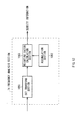
- a reference numeral 1 denotes an image processing system according to an embodiment of the present invention which roughly includes an image processing apparatus 2, a storage unit 22, and a plurality of video tape recorders 231 to 23n.
- the image processing system 1 is configured to load a part of or entire AV (Audio/Visual) data recorded on a video tape as a clip to a large-capacity storage unit 22 adopting RAID (Redundant Arrays of Independent Disks) technology through the image processing apparatus 2 or load still image data recorded on a video tape to the storage unit 22.
- AV Audio/Visual
- RAID Redundant Arrays of Independent Disks
- the image processing system 1 is configured to create an edit list specifying edition contents for obtaining desired edited video and audio by connecting AV data loaded to the storage unit 22 in a desired state and moreover, actually execute edition processing in accordance with the created edit list and store the obtained AV data as a new clip in the storage unit 22 or record the AV data on a video tape through any one of the video tape recorders 231 to 23n.
- a GPU 4 an EXR (Extreme Data Rate)-RAM 5, and a south bridge 6 are connected to a microprocessor 3.
- a hard disc drive 7, a USB interface 8, and an audio I/O codec 9 are connected to the south bridge 6.
- a speaker 41 is connected to the audio I/O codec 9.
- a mouse 38, a keyboard 39, video tape recorders 231 to 23n, a recording apparatus 22, and an operation controller 37 are connected to the south bridge 6 through a PCI bus 15.
- a display 40 is connected to the GPU 4.
- the microprocessor 3 is a multi-core processor in which a general-purpose main CPU core 3M for executing a basic program such as an OS (Operating System), a plurality of (eight in this case) signal processing processors (hereinafter, referred to as "sub CPU core") 3SA to 3SH of a RISC (Reduced Instruction Set Computer) type connected to the main CPU core 3M through an internal bus 12, a memory controller 13 for performing memory control on an XDR-RAM 5 having a capacity of, e.g., 256 [MByte], and an I/O (In/Out) controller 14 for managing data input and output between itself and south bridge 6 are integrated in one chip.
- This microprocessor 3 operates at an operating frequency of, e.g., 4 [GHz].
- the microprocessor 3 of the image processing system 1 mainly functions as a codec compatible with an existing video standard such as MPEG-2 or H.264/AVC (Advanced Video Coding) and is configured to transfer a playback image of video data obtained as a result of decode processing to the GPU 4, change settings such as a playback speed (to be described later) of the playback image of video data, transfer still image data to the GPU 4, or perform physical simulation.
- an existing video standard such as MPEG-2 or H.264/AVC (Advanced Video Coding)
- change settings such as a playback speed (to be described later) of the playback image of video data, transfer still image data to the GPU 4, or perform physical simulation.
- the eight sub CPU cores 3SA to 3SH function as decoders for a video stream obtained by encoding video data and can decode HD (High Definition) video stream in parallel.
- the main CPU core 3M which is configured to perform processing or management other than those performed by the eight sub CPU cores 3SA to 3SH, receives an instruction supplied from the mouse 38, the keyboard 39, or the operation controller 37 through the south bridge 6 and executes various processing according to the received instruction.
- the microprocessor 3 is configured to be able to decode video stream in parallel using the eight sub CPU cores 3SA to 3SH and transfer data between the microprocessor 3 and the GPU 4 at a transfer rate of up to 30 [GByte/sec] using a high bandwidth bus 10. That is, it is possible to decode and transfer many high definition video streams at short times.
- the GPU 4 performs final rendering processing concerning texture pasting required when a playback image of video data to be displayed on the display 40 is moved, coordinate conversion calculation required when a playback image of video data or a still image of still image data is displayed on the display 40, and enlargement/reduction processing for a playback image of video data or still image of still image data and thereby reduces a processing load of the microprocessor 3.
- the microprocessor 3 reads out a required application program stored in the hard disc drive 7 and develops the application program in the XDR-RAM 5 based on a control program in the hard disc drive 7 and, afterward, executes required control processing based on the application program and user operation.
- the microprocessor 3 When a display instruction of a clip capture window for importing an AV stream recorded on a video tape into the storage unit 22 is input by a user through the mouse 38, keyboard 39, or operation controller 37, the microprocessor 3 correspondingly controls the hard disc drive 7 so as to read out AV data corresponding to the display instruction and, at the same time, controls the GPU 4 to display the clip capture window based on the AV data on the display 40.
- the microprocessor 3 correspondingly controls the video tape recorders 231 to 23n so as to execute playback operation of AV data recorded on a video tape.
- an AV stream played back from a video tape loaded in the video tape recorders 231 to 23n is output from the video tape recorders 231 to 23n to the GPU 4 sequentially through the PCI bus 15, south bridge 6, and microprocessor 3.
- the GPU 4 applies predetermined signal processing to the supplied video data and sends the resultant video data to the display 40 under the control of the microprocessor 3, whereby a playback image based on the video data is displayed at a predetermined position in the clip capture window. Meanwhile, the microprocessor 3 sends an audio signal extracted from AV data to the speaker 41 through the audio I/O codec 9, whereby audio based on the audio signal is output from the speaker 41.
- a user can specify a desired playback video/audio part as a clip while viewing the playback image of video data displayed on the display 40 and hearing the playback audio of audio data output from the speaker 41 with the mouse 38, keyboard 39, or operation controller 37, and can register management information including time codes of the IN-point and OUT-point, clip length, clip ID, clip name, shooting time of the AV data, and creation time of the clip as metadata.
- This clip management information is registered in a clip management database in the hard disc drive 7 under the control of the microprocessor 3.
- the microprocessor 3 can register not only the abovementioned clip management information but also the feature amount of various parameters of video data constituting AV data as a metadata file.
- the microprocessor 3 correspondingly controls the video tape recorders 231 to 23n so as to play back the specified AV stream.
- a video stream or audio stream included in the AV stream played back from the video tape is output from the video tape recorders 231 to 23n.
- the video stream is then given to the GPU 4 sequentially through the PCI bus 15, south bridge 6, microprocessor 3, and bus 10.
- a user can display an edit window (to be described later) for performing editing work by a predetermined operation using the mouse 38, keyboard 39, or operation controller 37 on the display 40 and thereby can create an edit list specifying edition contents showing how to connect clips to each other by using the edit window. Moreover, the user can confirm edited video and edited audio according to the edit list after or while creating the edit list.
- the microprocessor 3 converts edit data created by all users specified in the edit list into a file and registers this file in an edit list database in the hard disc drive 7.
- the microprocessor 3 correspondingly controls the storage unit 22 so as to read a video stream and audio stream included in a required AV stream.
- the GPU 4 Under the control of the microprocessor 3, the GPU 4 applies predetermined signal processing to the video data obtained as a result of the video special effect processing and sends the resultant video signal to the display 40.
- the microprocessor 3 applies audio mixing to the audio data among the video data and audio data included in the AV data and sends the resultant audio data to the speaker 41 through the audio I/O codec 9.
- a playback image of the video data is displayed at a predetermined position in the edit window and a playback audio of the audio data is output from the speaker 41.
- the image processing system 1 allows the user to do editing work while confirming the playback image and playback audio based on the edit list.
- the microprocessor 3 and GPU 4 provided in the image processing apparatus 2 can execute, for a playback image on the edit screen displayed on the display 40, video display processing including special effect processing, as well as various advanced processing or edition processing.
- the video data that has simultaneously been decoded in parallel by the eight sub CPU cores 3SA to 3SH in the microprocessor 3 is transferred to the GPU 4 through the bus 10.
- the data transfer rate at this time is, e.g., up to 30 [GByte/sec] and, therefore, it is possible to display even a highly complex video data that has been subjected to special effect processing at high speed and smoothly.
- an edit mode and a view mode are prepared.
- the edit mode the abovementioned edition processing for generating edited video image data is executed.
- the view mode a classification display for allowing a user to easily manage or search for a large quantity of video image data and still image data stored in the storage unit 22 is executed.
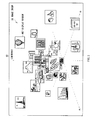
- the microprocessor 3 of the image processing apparatus 2 controls the hard disc drive 7 and GPU 4 so as to enter the view mode, whereby an edit window 50 shown in FIG. 2 is displayed on the display 40.
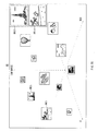
- the edit window 50 has a clip list display area 51, a storyboard area 52, a timeline area 53, an effect information display area 54, and a display area 55 that is unique to this edit window 50.
- editing work is mainly done on the display area 55, and the storyboard area 52 and the timeline area 53 are just supplementarily provided.
- the clip list display area 51 shows various bins and files being registered in the image processing apparatus 2.
- this clip list display area 51 shows a list of AV data being contained in the bin or file.
- the user selects desired AV data from the AV data as a moving picture from the clip list displayed in the clip list display area 51, drags and drops a desired clip onto the display area 55, whereby a display window W57 showing the first image (the first still image in the case of video data) of the AV data is displayed on the display area 55.
- a plurality of display windows W57 can be displayed on the display area 55.
- the user can click the display window W57 to cause the image processing apparatus 2 to play back the dragged-and-dropped AV data on the display area 55 and fast forward, fast rewind, or stop the displayed playback image.
- the user can search for a desired frame while visually confirming the playback image of the video data contained in the AV data through a plurality of display windows W57 on the display area 55 and specify a start point (hereinafter, referred to as IN-point) and an end point (hereinafter, referred to as OUT-point) of a desired video/audio part to be cut out from the AV data.
- a start point hereinafter, referred to as IN-point
- OUT-point an end point of a desired video/audio part to be cut out from the AV data.
- the microprocessor 3 of the image processing apparatus 2 enters the edit mode. In this state, the user can paste the video/audio part between the IN-point and OUT-point of thus specified AV data in the storyboard area 52 as new AV data by drag-and-drop operation.
- the edit window 50 arranges clips of editing-targeted AV data in the storyboard area 52, which allows the user to easily imagine an edited video.
- the storyboard area 52 shows the thumbnail and detailed information of the main image corresponding to the first image or the like of each pasted clip.
- the user sequentially arranges clips pasted on the storyboard area 52 on a video track of the timeline area 53 by drag-and-drop operation.
- a band (not shown) corresponding to a length of each pasted clip appears on the video track with a timeline as an index.
- a band (not shown) having the same length appears on an audio track at the same position indicated by the timeline.
- the microprocessor 3 of the image processing apparatus 2 displays a plurality of display windows W57 each having a predetermined frame size, which show the AV data selected by the user from the clip list displayed in the clip list display area 51 and dragged and dropped onto the display area 55, on the display area 55 of the edit window 50 to thereby present an image group 58.
- an additional clip can be dragged and dropped from the clip list display area 51 onto the display area 55 showing at least one display window W57, and one or some display windows existing on the display area 55 can be deleted according to user's selection/deletion operation.
- the image group 58 refers to a plurality of the first pictures (still images) of video data or representative picture (still image) which are arranged in the form of the display window W57 based on the feature amount (picture-basis or GOP-basis) of the video data in a three-dimensional display space in which parameters of "red (R)", "blue
- (B)" and “luminance,” are set respectively as X-axis, Y-axis, and Z-axis constituting display axes.
- the parameters constituting the respective display axes (X-axis, Y-axis, and Z-axis) in the three-dimensional display space can collectively referred to as "feature parameters" representing the feature of AV data containing video data.
- feature parameters representing the feature of AV data containing video data.
- the feature amount included in the feature parameters differs for each picture constituting the video data unless pictures of the same still image continue each other in terms of time.
- the display windows W57 are arranged based on the respective display axes such that the display window W57 showing a picture (still image) having a high red level video data included in the image group 58 is disposed on the lower right side of the display area 55, display window W57 showing a picture having a high luminance level video data included in the image group 58 is disposed on the upper central side of the display area 55, and display window W57 showing a picture having a high blue level video data included in the image group 58 is disposed on the lower left side of the display area 55.
- This arrangement allows the user to intuitively recognize rough distribution of the luminance or color component contained in a plurality of video data as an image.
- the microprocessor 3 of the image processing apparatus 2 can sequentially update a picture constituting the video data at an update speed according to a predetermined frame frequency in the display window W57, thereby displaying the video data as a moving picture.
- the microprocessor 3 of the image processing apparatus 2 rearranges the display window W57 according to the feature amount in the three-dimensional display space, whereby the display window W57 of the video data is displayed while moving on the three-dimensional display space.
- the image processing apparatus 2 can control the playback speed of the video data by changing the update speed of the picture.
- the update speed is increased, the video data can be played back at fast speed and, accordingly, the movement speed of the display window W57 is increased to allow the display window W57 to move at high speed on the three-dimensional display space.
- the movement speed of the display window W57 is decreased to allow the display window W57 to move at low speed in such a manner as if it were floating on the three-dimensional display space.
- the image processing apparatus 2 can fast-rewind plays back the video data in the display window W57.
- the display window W57 moves in the opposite direction to the above-described case.
- the image processing apparatus 2 can stop the display window W57 at a user's desired timing while the display window W57 is moving in the forward direction or backward direction so as to display a picture (still image) corresponding to this timing.
- the image processing apparatus 2 previously extracts the feature parameters representing the feature amount of the picture constituting the video data as metadata and, when displaying the playback image of the video data through the display window W57, rearranges the display window W57 on the three-dimensional virtual space according to the feature amounts of respective pictures to be updated.
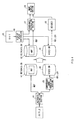
- the above configuration for moving the display window W57 will be described in terms of the function block constituted by the microprocessor 3 and GPU 4.
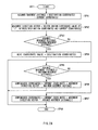
- a first configuration example is a method that previously extracts the feature parameters from respective pictures constituting the video data as metadata and uses the extracted feature parameters to display the video data.
- a second configuration example is a method that uses metadata to display the video data while generating the metadata from respective pictures constituting the video data.
- a third configuration example is a method that uses the feature parameters to display the video data while generating the feature parameters as metadata when the video data is encoded for recording.
- a metadata extraction section 61 extracts the feature parameters representing various feature amounts included in AV data containing video data and registers the extracted feature parameters in a metadata database (hereinafter, referred to as "metadata DB") 62 as a picture-basis or pictures-basis (e.g., GOP-basis) metadata file MDF corresponding to the video data.
- metadata DB a metadata database
- a compressed image generation section 63 compresses respective pictures of the video data supplied through the metadata extraction section 61 so as to register the compressed pictures in a video database (hereinafter, referred to as "video DB") 64 as a main-video stream HD1, as well as reduces the number of pixels of the pictures in the video data at a predetermined rate so as to register the pixel number reduced pictures in the video DB 64 as a sub-video stream LD1.
- video DB video database
- This configuration allows both the main-video stream HD1 whose pixel number has not been reduced and sub-video stream LD1 whose pixel number has been reduced to be stored in the video DB 64 in units of video data or in units of a predetermined time period.
- the microprocessor 3 can selectively use the main and sub-video streams in accordance with the position on the three-dimensional display space. For example, when the image size of the display window W57 needs to be reduced, the sub-video stream LD1 is used; on the other hand, when the image size of the display window W57 needs to be enlarged, the main-video stream HD1 is used.
- a display space controller 66 recognizes parameters of the display axes used for generation of the three-dimensional display space which is specified by a user through a Graphical User Interface (GUI) 65 displayed on the display area 55, recognizes viewpoint coordinates for presenting the image group 58 to the user, or makes various determinations concerning the display such as a determination of arranging the AV data selected by a user on the three-dimensional display space.
- GUI Graphical User Interface
- the display space controller 66 outputs frame numbers corresponding to a plurality of pictures constituting the video data to be displayed on the display area 55 as the image group 58 ( FIG. 3 ) to the metadata DB 62 based on the determination result to allow the metadata DB 62 to read out the metadata file MDF therefrom using the feature parameters of the picture corresponding to the frame number as the metadata and send the metadata file MDF to a coordinate calculation section 67.
- the display space controller 66 outputs the frame numbers of the pictures constituting the video data also to the video DB 64. This allows the sub-video stream LD1 corresponding to the frame numbers to be sent to a decoder 68 when the playback image of the video data is displayed through the display window W57, and allows the main-video stream HD1 corresponding to the frame numbers to be sent to the decoder 68 when the playback image of the video data is displayed in an enlarged manner.
- the decoder 68 decodes the sub-video stream LD1 and main-video stream HD1 supplied from the video DB 64 and sends the decoded sub- and main-video data to an image display section 69.
- the coordinate calculation section 67 sets the feature parameters supplied from the display space controller 66 to the display axes of the display space, converts the feature parameters into coordinates (coordinate parameters) of the three-dimensional display space by calculation, and determines the arrangement on the three-dimensional display space according to the obtained coordinate parameter values. Then, based on the viewpoint coordinate with respect to the image group 58 including a plurality of display windows W57 to be arranged on the three-dimensional display space and positions of the respective display windows W57, the coordinate calculation section 67 determines the display size of each display window W57 and sends various information (display parameters) concerning the display of each display window W57 to the image display section 69.
- the image display section 69 uses the coordinate parameters received from the coordinate calculation section 67 to determine the three-dimensional coordinate positions on the three-dimensional display space on which the sub-video data supplied from the decoder 68 is arranged and arranges a display window W57 corresponding to the sub-video data on the three-dimensional display space. After executing the above processing for display windows W57 corresponding to other video data, the image display section 69 converts the coordinate parameters of the display windows W57 into the two-dimensional coordinate positions (display position parameters) of the display area 55 to thereby display the image group 58 including a plurality of display windows W57 on the display area 55.
- the display space controller 66 recognizes the feature parameters set to the display axes of the three-dimensional display space which is specified by a user through the GUI 65 displayed on the display area 55 or recognizes viewpoint coordinates for presenting the image group 58 to the user. Further, the display space controller 66 makes various determinations concerning the display such as a determination of arranging the video data selected by a user on the three-dimensional display space and sends this determination to the coordinate calculation section 67.
- the display space controller 66 outputs the frame numbers of the pictures constituting the video data also to the video DB 64 based on the determination result to allow the sub-video stream LD1 corresponding to the frame numbers to be sent to the decoder 68 when the playback image of the video data is displayed through the display window W57, and allow the main-video stream HD1 corresponding to the frame numbers to be sent to the decoder 68 when the playback image of the video data is displayed in an enlarged manner.
- both the main-video stream HD1 that has been encoded with the pixel number thereof not reduced and sub-video stream LD1 that has been encoded with the pixel number thereof reduced are previously stored in the video DB 64.
- the decoder 68 decodes the sub-video stream LD1 and main-video stream HD1 supplied from the video DB 64 and sends the decoded main-video data to the metadata extraction section 61 and decoded sub-video data to the image display section 69.
- the metadata extraction section 61 extracts the feature parameters included in the main-video data supplied from the decoder 68 as metadata and registers the extracted metadata in the metadata DB 62 as the metadata file MDF, as well as sends this metadata file MDF to the coordinate calculation section 67.
- the coordinate calculation section 67 generates the three-dimensional display space in which the feature parameters supplied from the display space controller 66 are set to the display axes by calculation, converts the feature amounts represented by the feature parameters of the video data to be displayed on the respective display windows W57 into coordinate parameters in the three-dimensional display space, and determines the arrangement on the three-dimensional display space according to the obtained coordinate parameter values. Then, based on the viewpoint coordinate with respect to the image group 58 including a plurality of display windows W57 to be arranged on the three-dimensional display space and positions of the respective display windows W57, the coordinate calculation section 67 determines the display size of each display window W57 and sends various information (display parameters) concerning the display of each display window W57 to the image display section 69.
- the coordinate calculation section 67 determines the display size of each display window W57 and sends various information (display parameter) concerning the display of each display window W57 to the image display section 69.
- the image display section 69 uses the coordinate parameters received from the coordinate calculation section 67 to determine the three-dimensional coordinate positions (coordinate parameters) on the three-dimensional display space on which the sub-video data supplied from the decoder 68 and arranges a display window W57 corresponding to the sub-video data on the three-dimensional display space. After executing the above processing for display windows W57 corresponding to other video data, the image display section 69 converts the three-dimensional coordinate parameters of a plurality of display windows W57 into the two-dimensional coordinate positions (display position parameters) of the display area 55 to thereby display the image group 58 including a plurality of display windows W57 on the display area 55.
- the display space controller 66 recognizes the feature parameters set to the display axes of the three-dimensional display space which is specified by a user through the GUI 65 or recognizes viewpoint coordinates for presenting the image group 58 to the user. Further, the display space controller 66 makes various determinations concerning the display such as a determination of arranging the video data selected by a user on the three-dimensional display space and sends this determination to the coordinate calculation section 67.
- the display space controller 66 outputs the frame numbers of the pictures constituting the video data to a metadata and video database (hereinafter, referred to as "metadata/video DB") 70 based on the determination result.
- metadata/video DB a metadata and video database
- This metadata/video DB 70 stores the main-video stream HD1 picked up and encoded by an image pickup device, as well as sub-video stream LD1 obtained by encoding sub-video data which is obtained by reducing the pixel number of the main-image data.
- the metadata/video DB 70 sends the sub-video stream LD1 corresponding to the frame numbers to the decoder 68.
- the metadata/video DB 70 sends the main-video stream HD1 corresponding to the frame numbers to the decoder 68.
- the metadata/video DB 70 stores the feature parameters included in the main-video data which has been extracted by a metadata extraction section incorporated in the image pickup device at the shooting time of the main-video data as a metadata file MDF.
- the metadata/video DB 70 sends the feature parameters corresponding to the frame numbers supplied from the display space controller 66 to the coordinate calculation section 67 as the metadata file MDF.
- the coordinate calculation section 67 generates the three-dimensional display space in which the feature parameters supplied form the display space controller 66 are set to the display axes by calculation, converts the feature parameters of the video data to be displayed on the respective display windows W57 into coordinate parameters in the three-dimensional display space, and determines the arrangement on the three-dimensional display space according to the obtained coordinate parameter values. Then, based on the viewpoint coordinate with respect to the image group 58 including a plurality of display windows W57 to be arranged on the three-dimensional display space and positions of the respective display windows, the coordinate calculation section 67 determines the display size of each display window W57 and sends various information concerning the display of each display window W57 to the image display section 69.
- the decoder 68 decodes the sub-video stream LD1 or main-video stream HD1 supplied from the metadata/video DB 70 and sends the decoded main-video data or sub-video data to the image display section 69.
- the image display section 69 uses the coordinate parameters received from the coordinate calculation section 67 to determine the three-dimensional coordinate positions (coordinate parameters) on the three-dimensional display space on which the sub-video data supplied from the decoder 68 and arranges a display window W57 corresponding to the sub-video data on the three-dimensional display space. After executing the above processing for display windows W57 corresponding to other video data, the image display section 69 converts the three-dimensional coordinate parameters of a plurality of display windows W57 into the two-dimensional coordinate positions (display position parameters) of the display area 55 to thereby display the image group 58 including a plurality of display windows W57 on the display area 55.
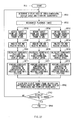
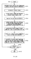
- the metadata extraction section 61 includes a density information calculation section 71, a motion detection section 72, a DCT vertical/horizontal frequency component detection section 73, a color component detection section 76, an audio detection section 80, a luminance/color difference detection section 83, and a metadata file generation section 86 in order to extract the feature parameters including various feature amounts corresponding to a density (complexity), a motion vector, a DCT (Discrete Cosine Transform) vertical/horizontal frequency component, a color component, and a audio level of each picture constituting the video data.
- the metadata extraction section 61 may include additional detection sections for extracting the feature amounts of parameters other then the above.
- the density information calculation section 71 includes an average value calculation section 1071, a difference value calculation section 1072, and an accumulation section 1073. Video data is supplied to the average value calculation section 1071 and difference value calculation section 1072.
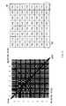
- the average value calculation section 1071 sequentially sets the frames constituting the video data as a target frame and divides the target frame into, e.g., 8 ⁇ 8 pixel blocks as shown in FIG. 8 . Further, the average value calculation section 1071 calculates the average value of the pixel values of respective blocks on the target frame and supplies the obtained average value to the difference value calculation section 1072.
- the difference value calculation section 1072 divides the target frame into, e.g., 8 ⁇ 8 pixel blocks in the same manner as the average value calculation section 1071 and calculates an absolute value
- the accumulation section 1073 accumulates the absolute values
- of the difference values calculated for the respective pixels of the blocks sequentially supplied from the difference value calculation section 1072 to obtain an accumulation value Q ⁇
- the accumulation section 1073 calculates the total sum of the accumulation values Q obtained for all the blocks of the target frame and outputs the total sum to the metadata file generation section 86 as target frame density information QS1.
- the total sum of the accumulation value Q obtained for the target frame is referred to as "Intra-AC".
- a motion vector detection section 1041 divides the previous frame into macroblocks each having 16 x 16 pixels and detects each 16 x 16 pixel block (hereinafter, referred to as "similar block") in the target frame that is most similar to each macroblock in the previous frame. Then, the motion vector detection section 1041 calculates a vector starting from the upper left of the macroblock and ending at the upper left of the similar block as a motion vector ⁇ F0 (h,v) of the macroblock.
- D0 ⁇
- the total sum D0 ⁇
- the dispersion of the motion vectors obtained for the macroblocks in the previous frame can be used as the statistical amount.
- FIG. 10 shows another configuration of the motion detection section 72 of FIG. 7 .
- This motion detection section 72A includes a histogram creation section 1051, a histogram storage section 1052, and a difference calculation section 1053.
- the histogram creation section 1051 sequentially sets the frames constituting the video data as a target frame, creates a simple histogram of the pixel values of the target frame, and supplies this histogram created for each target to the histogram storage section 1052 and difference calculation section 1053.
- the histogram storage section 1052 stores the histogram of the target frame supplied from the histogram creation section 1051.
- the histogram storage section 1052 has a storage capacity large enough to store at least histograms corresponding to two frames and thus stores the histogram of the target frame supplied from the histogram creation section 1051 and histogram of the previous target frame (i.e., previous frame).
- the difference calculation section 1053 calculates a difference absolute sum (to be described later) of the histogram of the target frame supplied from the histogram creation section 1051 and histogram of the previous frame stored in the histogram storage section 1052 and outputs the calculation result as the motion information D0 of the target frame.
- the histogram creation section 1051 equally divides the range of 0 to 255 into, e.g., 8 small ranges of 0 to 31, 32 to 63, 64 to 95, 96 to 127, 128 to 159, 160 to 191, 192 to 223, 224 to 255 and calculates the frequency of occurrence of the pixel values included in the each small range to thereby create the simple histogram of the target frame.
- the difference calculation section 1053 calculates an absolute value ⁇ (shadowed portions in FIG. 11 ) of the difference value between the frequency in (i+1)-th frame which is the target frame and frequency in i-th frame which is the previous frame in the same small range. Further, the difference calculation section 1053 calculates a total sum (difference absolute sum) ⁇ of the absolute value of the difference value of the frequency obtained for respective 8 small ranges in the histogram and outputs the obtained total sum ⁇ to the metadata file generation section 86 as the motion information D0 of the target frame.
- FIG. 12 shows a configuration example of a frequency analysis section 74 in the DCT vertical/horizontal frequency component detection section 73 ( FIG. 7 ).
- the frequency analysis section 74 includes a DCT transform section 1061, a weighting factor calculation section 1062, and an accumulation section 1063.
- the DCT transform section 1061 When video data is supplied to the DCT transform section 1061, the DCT transform section 1061 sequentially sets the frames constituting the video data as a target frame and divides the target frame into 8 ⁇ 8 pixel blocks. Further, the DCT transform section 1061 DCT transforms the respective blocks in the target frame and supplies 8 ⁇ 8 DCT coefficients obtained for respective blocks to the accumulation section 1063.
- the weighting factor calculation section 1062 calculates the weights to be added respectively to the 8 ⁇ 8 DCT coefficients and supplies the weights to the accumulation section 1063.
- the accumulation section 1063 adds the weights supplied from the weighting factor calculation section 1062 respectively to the 8 ⁇ 8 DCT coefficients supplied from the DCT transform section 1061 so as to perform accumulation to thereby obtain an accumulation value for each block. Further, the accumulation section 1063 calculates the total sum of the accumulation values obtained for respective blocks and sends the total sum to a vertical line/horizontal line level calculation section 75 ( FIG. 7 ) as the density information of the target frame.
- the left side of FIG. 13 shows a base image after DCT transform.
- the base image is composed of 8 x 8 patterns (frequency components). In this base image, the frequency component becomes higher toward the right side and lower side.
- the DCT coefficient F (i-1, j-1) represents the degree (rate) at which the frequency component of a pattern which is i-th from the left and j-th from the top of the base image is included in the base image.
- the numerals appearing in the base image of the left side of FIG. 13 each indicate a weight G (i-1, j-1) calculated by the weighting factor calculation section 1062 of FIG. 12 .
- the weight G (i-1, j-1) is a weight to be added to the DCT coefficient F (i-1, j-1).
- the accumulation section 1063 calculates a total sum K of the accumulation values V obtained for all the blocks in the target frames and outputs the total sum K to the vertical line/horizontal line level calculation section 75 as the density information of the target frame.
- the vertical line/horizontal line level calculation section 75 of the DCT vertical/horizontal frequency component detection section 73 detects that an image of the target frame includes fine vertical lines, that is, the image has a high frequency component in the horizontal direction based on the DCT coefficient in an area AR1 of the target frame or that the image of the target frame includes fine horizontal lines, that is, the image has a high frequency component in the vertical direction based on the DCT coefficient in an area AR2 of the target frame.
- the DCT vertical/horizontal frequency component detection section 73 can determine the density (complexity) level of the image of the target frame using the frequency analysis section 74 and determines the levels of the horizontal frequency and vertical frequency using the vertical line/horizontal line level calculation section 75.
- the obtained information is then output to the metadata file generation section 86 as a DCT vertical/horizontal frequency component information FVH.
- the color component detection section 76 includes a pixel RGB level detection section 77, an RGB level statistic/dispersion detection section 78, and an HLS level statistic/dispersion detection section 79.
- the supplied video data is input to the pixel RGB level detection section 77.
- the pixel RGB level detection section 77 detects the RGB levels of each pixel in the target frame of the video data and sends the detected RGB levels to the RGB level statistic/dispersion detection section 78 and HLS level statistic/dispersion detection section 79.
- the RGB level statistic/dispersion detection section 78 calculates the statistic and dispersion of the RGB levels of each pixel in the target frame supplied from the pixel RGB level detection section 77 and outputs the statistic representing the levels of the respective color components of RGB in the target frame and dispersion value representing whether the color components in the target frame are added globally or locally to the metadata file generation section 86 as color component information CL1.
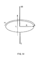
- the HLS level statistic/dispersion detection section 79 converts the RGB levels of each pixel in the target frame supplied from the pixel RGB level detection section 77 into three components of "Hue”, “Saturation”, and “Luminance/Lightness”, calculates the statistic and dispersion value of each of the above elements in an HLS space composed of the hue, saturation, and luminance, as shown in FIG. 14 , and outputs the detection result to the metadata file generation section 86 as HLS information CL2.
- the hue in the HLS space is represented by an angle from 0° to 359°, in which 0° is red and 180° is blue green opposed to red. That is, in the HLS space, it is easy to find an opposing color.
- the saturation in the HLS space is the mixing rate of chromatic color.
- the HLS space unlike an HSV (Hue, Saturation, and Value) space, is based on the idea that a reduction of the saturation form pure color means that the color has more grey. That is, the lower saturation means the color is near gray, and higher saturation means that the color is away from gray.
- the luminance in the HLS space which differs from the case of the HSV space where luminance 100% is set as a pure color and how much the luminance level is lost from the 100% luminance state is represented, is an index in which luminance 0% is black, luminance 100% is white, and luminance 50% is pure white.
- the HLS level statistic/dispersion detection section 79 can output the HLS information CL2 which represents the hue in a far more understandable manner than the RGB space to the metadata file generation section 86.
- the feature parameters are extracted from the video data.
- the feature amount representing the feature of audio data can be calculated from audio data corresponding to the video data as the feature parameters. That is, the feature parameters are parameters that can be applied to both the video data and audio data.
- the audio detection section 80 ( FIG. 7 ) includes a frequency analysis section 81 and a level detection section 82. Video data supplied to the audio detection section 80 is input to the frequency analysis section 81.
- the frequency analysis section 81 analyzes the frequency of audio data corresponding to the target frame of the video data and notifies the level detection section 82 of its frequency band.
- the level detection section 82 detects the level of audio data in the frequency band notified from the frequency analysis section 81 and outputs the detected level to the metadata file generation section 86 as audio level information AL.
- the luminance/color difference detection section 83 ( FIG. 7 ) includes a Y/Cb/Cr level detection section 84 and a Y/Cb/Cr level statistic/dispersion detection section 85. Video data supplied to the luminance/color difference detection section 83 is input to the Y/Cb/Cr level detection section 84.
- the Y/Cb/Cr level detection section 84 detects the luminance level of a luminance signal Y and signal levels of a color difference signals Cb and Cr for each pixel in the target frame of the video data and supplies the detected levels to the Y/Cb/Cr level statistic/dispersion detection section 85.
- the Y/Cb/Cr level statistic/dispersion detection section 85 calculates the statistic and dispersion value of the luminance level of the luminance signal Y and signal levels of the color difference signals Cb and Cr of each pixel in the target frame which is supplied from the Y/Cb/Cr level detection section 84 and outputs the statistic representing the levels of the luminance signal Y, color difference signals Cb and Cr and dispersion value of the luminance signal Y, color difference signals Cb and Cr in the target frame to the metadata file generation section 86 as color component information CL3.
- the metadata file generation section 86 Based on the density information QS1 supplied from the density information calculation section 71, motion information D0 of the target frame supplied from the motion detection section 72, DCT vertical/horizontal frequency component information FVH supplied from the DCT vertical/horizontal frequency component detection section 73, color component information CL1 and HLS information CL2 supplied from the color component detection section 76, audio level information AL supplied from the audio detection section 80, and color component information CL3 supplied from the luminance/color difference detection section 83, the metadata file generation section 86 generates the feature parameters of the pictures constituting the video data and feature parameters of the audio data corresponding to the video data respectively as a metadata file MDF including metadata and outputs them.
- various feature parameters such as “time code”, “motion amount”, “density”, “red”, “blue”, “green”, “luminance”, “red dispersion”, “green dispersion”, “hue”, “saturation”, “vertical line”, “horizontal line”, “motion dispersion”, and “audio level” are registered for respective pictures (from the first to last frames) constituting the video data.
- normalized relative values between 0 and 1 are used as the feature amount values in the respective feature parameters of the metadata file MDF, an absolute value may be used.
- contents of the metadata file MDF are not limited to the above mentioned feature parameters. For example, after the display window W57 has been arranged on the three-dimensional display space, the coordinate value on the three-dimensional display space on which the display window W57 has actually been arranged may be registered as the metadata.
- the image processing apparatus 2 when the coordinate value on the three-dimensional display space is registered in the metadata file MDF as described above, it is not necessary to additionally calculate the coordinate parameters in the three-dimensional display space based on the feature parameters in order to arrange the next display window W57 of the video data on the three-dimensional display space, whereby the display window W57 can be arranged on the three-dimensional display space in a moment.
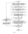
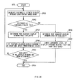
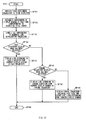
- a display processing procedure for video data and display processing procedure for a plurality of video data which are performed by the microprocessor 3 of the image processing apparatus 2 will concretely be described using flowcharts.
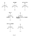
- the microprocessor 3 of the image processing apparatus 2 executes an initialization step of routine RT1 and proceeds to the next step SP1 where it determines the display axes of the three-dimensional display space specified by a user and viewpoint coordinates for displaying the image group 58 to the user, followed by proceeding to step SP2.
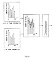
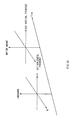
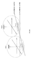
- the microprocessor 3 of the image processing apparatus 2 can determine the display axes so as to generate various types of three-dimensional display spaces such as: three-dimensional display space defined by R-axis, G-axis, and B-axis representing color components of RGB ( FIG. 17 (A) ); three-dimensional display space defined by luminance level axis, R-axis, and B-axis ( FIG. 17 (B) ); three-dimensional display space defined by motion vector axis, Cb-axis, and Cr-axis ( FIG. 17 (C) ); three-dimensional display space defined by density information axis, luminance level axis, and hue axis ( FIG.
- FIG. 17 (D) three-dimensional display space defined by R-axis, DCT vertical frequency axis, and DCT horizontal frequency axis
- FIG. 17 (E) three-dimensional display space defined by DCT vertical frequency axis, Cb-axis, and Cr-axis
- FIG. 17 (F) three-dimensional display space defined by L (Luminance)-axis, H (Hue)-axis, and S (Saturation)-axis which are elements of the HLS space
- the display axes used for generating the three-dimensional display space are not limited to the above, but it is possible to use another combination of feature parameters registered in the metadata file as the display axes.
- step SP2 the microprocessor 3 of the image processing apparatus 2 recognizes a picture (still image) of the video data to be played back which is specified by the user and then proceeds to step SP3.
- step SP3 the microprocessor 3 sets the still image as a target frame, decodes its sub-video stream LD1, transfers decoded sub-video data to the GPU 4, and proceeds to step SP4.
- step SP4 the microprocessor 3 of the image processing apparatus 2 inquires for the feature amounts of the feature parameters used as the display axes of the three-dimensional display space, receives them from the metadata file MDF associated with the still image, and proceeds to step SP5.
- step SP5 the microprocessor 3 of the image processing apparatus 2 calculates the coordinate position (coordinate parameters) on the three-dimensional display space on which the display window W57 of the still image is pasted based on the feature amounts of the feature parameters received in step SP4 and proceeds to step SP6. That is, the microprocessor 3 of the image processing apparatus 2 converts the feature amounts corresponding to the display axes that the still image has into the coordinate value on the three-dimensional display space.
- step SP6 the microprocessor 3 of the image processing apparatus 2 determines whether the current still image is the last image to be displayed or not. When an affirmative result is obtained, which means that the still image other than the current still image has not been specified by the user, that is, there is not any other display window W57 to be displayed, the microprocessor 3 proceeds to step SP7.
- step SP6 which means that the picture (still image) of the video data other than the current still image has been specified by the user, that is, there is another display window W57 corresponding to the still image to be displayed
- the microprocessor 3 of the image processing apparatus 2 returns to step SP2 where it repeats the abovementioned processing to thereby calculate the coordinate positions on the three-dimensional display space for a plurality of display windows W57 corresponding to a plurality of still images according to the feature amounts set in the feature parameters of the respective still images.
- step SP7 the microprocessor 3 of the image processing apparatus 2 allows the GPU 4 to paste the display window W57 corresponding to the still image on the three-dimensional display space based on the coordinate parameters (coordinate positions) calculated in step SP5, convert the coordinate parameters (coordinate positions) on the three-dimensional display space into a two-dimensional coordinate position (display position parameters) on the two-dimensional screen of the display area 55 based on the viewpoint coordinates determined in step SP1, determine the display size of each display window W57, and plot the display window W57 on the two-dimensional coordinate position for display.
- the microprocessor 3 of the image processing apparatus 2 proceeds to step SP8.
- the microprocessor 3 of the image processing apparatus 2 arranges a plurality of display windows W57 corresponding to the plurality of still images on the respective coordinate positions (positions represented by the coordinate parameters) according to the feature parameters of the still images as the image group 58 composed of the plurality of display windows W57.
- step S8 the microprocessor 3 of the image processing apparatus 2 determines whether to end display processing for the display window W57 based on whether there has been issued a termination instruction from the user or whether a predetermined time has elapsed. When an affirmative result is obtained, the microprocessor 3 proceeds to step SP11 where it ends the display processing.
- step SP8 the microprocessor 3 of the image processing apparatus 2 proceeds to step SP9 without ending the display processing for the display window W57.
- step SP9 the microprocessor 3 of the image processing apparatus 2 waits until the viewpoint coordinates of the display window W57 are changed by user's cursor operation and then proceeds to subsequent step SP10.
- step SP10 the microprocessor 3 of the image processing apparatus 2 determines whether the viewpoint coordinates of the display window W57 have actually been changed by the user. When a negative result is obtained, the microprocessor 3 returns to step SP7 where it continues displaying the display window W57 of the still image at the original coordinate position. On the other hand, when an affirmative result is obtained, the microprocessor 3 returns to step SP1, where it determines new viewpoint coordinates after change, repeats the processing of step SP2 and subsequent steps, and rearranges the display window W57 on the three-dimensional display space based on the new viewpoint coordinates.
- the microprocessor 3 of the image processing apparatus 2 arranges the display window W57 such that the display window W57 is always positioned right in front of the user irrespective of the change of the viewpoint, allowing the user to always visually confirm the display window W57 from the front.
- the microprocessor 3 of the image processing apparatus 2 can arrange the display window W57 of the still image on the coordinate position on the three-dimensional display space according to the feature parameter that the still image of the video data has.
- the microprocessor 3 can present the plurality of still images as the image group 58 ( FIG. 3 ) composed of the display windows W57 of the still images corresponding to the plurality of video data, thereby allowing the user to intuitively grasp the overall trend of the plurality of video data as an image through the image group 58.
- the microprocessor 3 of the image processing apparatus 2 can present a zoom-up image group 58Z1 in which a large number of display windows W57 of the still images having fine vertical lines are arranged near the DCT horizontal frequency axis as shown in FIG. 18 .
- the microprocessor 3 of the image processing apparatus 2 can present a zoom-up image group 58Z2 in which a large number of display windows W57 of the still images having a strong red component are arranged near the R-axis as shown in FIG. 19 .
- the microprocessor 3 of the image processing apparatus 2 can present a zoom-up image group 58Z3 in which a large number of display windows W57 of the still images having a strong green component are arranged near the G-axis as shown in FIG. 20 .
- the display processing procedure for video data (moving picture) is basically the same as the abovementioned display processing routine RT1 for a picture (still image) of video data. That is, the same processing as the display processing routine RT1 for a still image is executed every time a picture (still image) constituting the video data is updated according to a predetermined frame frequency.
- the microprocessor 3 of the image processing apparatus 2 executes an initialization step of routine RT2 and proceeds to the next step SP21 where it determines the display axes of the three-dimensional display space specified by a user and viewpoint coordinates for displaying the image group 58 to the user, followed by proceeding to step SP22.
- step SP22 the microprocessor 3 of the image processing apparatus 2 recognizes a still image of the video data to be played back which is specified by the user and then proceeds to step SP23.
- step SP23 the microprocessor 3 of the image processing apparatus 2 sets the still image as a target frame, decodes its sub-video stream LD1, transfers decoded sub-video data to the GPU 4, and proceeds to step SP24.
- step SP24 the microprocessor 3 of the image processing apparatus 2 inquires for the feature amounts of the feature parameters used as the display axes of the three-dimensional display space, receives them from the metadata file MDF associated with the still image, and proceeds to step SP5.
- step SP25 the microprocessor 3 of the image processing apparatus 2 calculates the coordinate parameters (coordinate positions) on the three-dimensional display space on which the display windows W57 corresponding to the still images constituting the video data are pasted based on the feature amounts of the feature parameters received in step SP24 and proceeds to the next sub-routine SRT1. That is, the microprocessor 3 of the image processing apparatus 2 converts the feature amounts of the feature parameters into the coordinate parameters (coordinate positions) of the three-dimensional display space having the display axes to which the feature parameters that the respective pictures (still images) constituting the video data have are set.
- sub-routine SRT1 the microprocessor 3 of the image processing apparatus 2 performs coordinate compensation processing based on a mutual positional relationship between the coordinate parameters (coordinate positions) on the three-dimensional display space of a previously-displayed still image and coordinate parameters (coordinate positions) on the three-dimensional display space of a still image to be displayed after update to calculate compensated coordinates and proceeds to step SP26.
- This coordinate compensation processing procedure in the sub-routine SRT1 will be described later.
- step SP26 the microprocessor 3 of the image processing apparatus 2 allows the GPU 4 to paste the display windows W57 corresponding to the still images constituting the video data on the three-dimensional display space based on the coordinate position on the three-dimensional display space calculated in step SP25 or compensated coordinate obtained in the sub-routine SRT1, convert the coordinate position on the three-dimensional display space into a two-dimensional coordinate position (display position parameters) on the two-dimensional screen of the display area 55 based on the viewpoint coordinates determined in step SP21, determine the display size of each display window W57, and plot the display window W57 on the two-dimensional coordinate position in the update order of the still image for display.
- the microprocessor 3 of the image processing apparatus 2 proceeds to step SP27.
- step SP27 the microprocessor 3 of the image processing apparatus 2 determines whether to end display processing for the display window W57 corresponding to the still image of the video data based on whether there has been issued a termination instruction from the user or whether a predetermined time has elapsed. When an affirmative result is obtained, the microprocessor 3 proceeds to step SP28 where it ends the display processing for the display window W57.
- step SP27 the microprocessor 3 of the image processing apparatus 2 does not end the display processing for the display window W57 but returns to step SP21 where it executes the display processing for the display window W57 corresponding to the video data to be specified next.
- the microprocessor 3 of the image processing apparatus 2 arranges the display window W57 of a still image on the coordinate position on the three-dimensional display space on which the feature parameters that the still image constituting the video data has are set to the display axes and changes the coordinate position (coordinate parameters) on the three-dimensional display space for rearrangement in accordance with a change of the feature amounts of the feature parameters of the still image occurring every time the still image of the display window W57 arranged on the three-dimensional display space is updated according to a predetermined frame frequency to thereby give the user an impression as if the display window W57 moved in a floating manner on the three-dimensional display space every time the still image of the display window W57 is updated.
- This allows the user to intuitively and instantly recognize the time-series feature (trend) of the video data as a motion image of the display window W57 changing along with the progress of the playback image.
- the display processing procedure for a plurality of video data is basically the same as the abovementioned display processing routine RT2 for one video data. That is, the microprocessor 3 of the image processing apparatus 2 performs display processing for each video data in a simultaneous and parallel manner so as to display the display windows W57 in a moving manner in accordance with a change of the feature parameters of the still images occurring every time the respective still images are updated while changing the positions on the three-dimensional display space.
- the microprocessor 3 of the image processing apparatus 2 executes an initialization step of routine RT3 and proceeds to the next step SP31 where it determines the display axes of the three-dimensional display space specified by a user and viewpoint coordinates for displaying the image group 58 to the user, followed by proceeding to step SP32.
- step SP32 the microprocessor 3 of the image processing apparatus 2 recognizes respective still images of a plurality of video data to be played back which are specified by the user and then proceeds to steps SP33, SP36, and SP39.
- steps SP33, SP36, and SP39 the microprocessor 3 of the image processing apparatus 2 sets the still images as target frames, decodes their sub-video streams LD1, transfers decoded sub-video data respectively to the GPU 4, and proceeds to steps SP34, SP37, and SP40.
- steps SP34, SP37, and SP40 the microprocessor 3 of the image processing apparatus 2 inquires for the feature amounts of the feature parameters used as the display axes of the three-dimensional display space, receives them from the metadata files MDF associated with the respective still images, and proceeds to subsequent steps SP35, SP38, and SP41.
- the microprocessor 3 of the image processing apparatus 2 calculates the coordinate parameters (coordinate positions) on the three-dimensional display space on which the display windows W57 corresponding to the still images constituting the respective video data are pasted based on the feature amounts of the feature parameters received in steps SP34, SP37, and SP40 and proceeds to the next sub-routine SRT1. That is, the microprocessor 3 of the image processing apparatus 2 converts the feature amounts of the feature parameters into the coordinate parameters (coordinate positions) of the three-dimensional display space having the display axes to which the feature parameters that the respective still images constituting a plurality of video data have are set.
- the microprocessor 3 of the image processing apparatus 2 performs coordinate compensation processing based on a mutual positional relationship between the coordinate parameters (coordinate positions) on the three-dimensional display space of a previously-displayed still image and coordinate parameters (coordinate positions) on the three-dimensional display space of a still image to be displayed after update to calculate compensated coordinates and proceeds to step SP42.
- step SP42 the microprocessor 3 of the image processing apparatus 2 allows the GPU 4 to paste the display windows W57 corresponding to the still images constituting the video data on the three-dimensional display space based on the coordinate positions respectively on the three-dimensional display space calculated in steps SP35, SP38, and SP41, convert the coordinate positions on the three-dimensional display space respectively into two-dimensional coordinate positions (display position parameters) on the two-dimensional screen of the display area 55 based on the viewpoint coordinates determined in step SP31, determine the display sizes of respective display windows W57, and plot the display windows W57 on the two-dimensional coordinate positions to thereby display the image group 58.
- the microprocessor 3 of the image processing apparatus 2 proceeds to subsequent step SP43.
- step SP43 the microprocessor 3 of the image processing apparatus 2 determines whether to end display processing for the image group 58 based on whether there has been issued a termination instruction from the user or whether a predetermined time has elapsed. When an affirmative result is obtained, the microprocessor 3 proceeds to step SP44 where it ends the display processing for the image group 58 composed of a plurality of display windows W57 corresponding to a plurality of video data.
- step SP44 the microprocessor 3 of the image processing apparatus 2 does not end the display processing for the image group 58 but returns to step SP31 where it executes the display processing for the display window W57 corresponding to the video data to be specified next.
- the microprocessor 3 of the image processing apparatus 2 arranges a plurality of display windows W57 corresponding to a plurality of still images on the coordinate parameters (coordinate positions) on the three-dimensional display space according to the feature amounts of the feature parameters of display axes that the respective still images in a plurality of video data have and changes the coordinate parameters (coordinate positions) on the three-dimensional display space, respectively, for rearrangement in accordance with a change of the feature amounts of the feature parameters of the still images occurring every time the still images of the display windows W57 arranged on the three-dimensional display space are updated according to a predetermined frame frequency to thereby give the user an impression as if the display windows W57 moved in a floating manner on the three-dimensional display space every time the still images of the display windows W57 are updated.
- This allows the user to intuitively and instantly recognize the time-series feature (trend) of a plurality of video data as motion images of the display windows W57 changing along with the progress of the playback images.
- the display windows W57 corresponding to the respective video data move in the same floating manner and in the same direction.
- the display windows W57 corresponding to the respective video data float in a different floating manner and in the different directions.
- the user when the video data that the user wants to focus on is selected by the user, the user easily focuses attention only on the display window W57 corresponding to the selected video data and, therefore, the user can easily grasp the feature (trend) of the video data through an impactful image representing a change of the motion of the display window W57.
- the microprocessor 3 of the image processing apparatus 2 arranges the display window W57 at a position PO1 of the lower left corner of the screen in accordance with the feature amount represented by the feature parameter corresponding to B-axis that the still image has.
- the microprocessor 3 of the image processing apparatus 2 rearranges the display window W57 of the updated still image at a position PO2 from the position PO1 in accordance with the feature amount of the blue component in this updated still image.
- the microprocessor 3 of the image processing apparatus 2 rearranges the display window W57 of the updated still image at a position PO3 from the position PO2 in accordance with the feature amount of the blue component in this updated still image.
- the microprocessor 3 of the image processing apparatus 2 rearranges the display window W57 while changing the coordinate position on the three-dimensional display space in accordance with the feature amounts of the feature parameters of the respective still images every time the still image of the video data is updated. This allows the user to visually confirm a state where as if the display window W57 corresponding to the video data moved on the screen of the display area 55 in a floating manner.
- the microprocessor 3 of the image processing apparatus 2 does not allow the display window W57 to jump to a destination in a single action at the time of scene change as shown in FIG. 25 but allows the display window W57 to gradually move to a destination while adjusting the movement speed of the display window W57 (allows the display window W57 to move in a stepwise manner).
- the microprocessor 3 of the image processing apparatus 2 performs compensation calculation to obtain compensated coordinates in addition to the coordinates of the original destination to thereby allow the display window W57 to once move to the position represented by the compensated coordinates, thus allowing the user to follow the motion of the display window W57.
- the microprocessor 3 of the image processing apparatus 2 executes an initialization step of sub-routine RT1 and proceeds to the next step SP61.
- step SP61 at the time of update of the still image of the video data, the microprocessor 3 of the image processing apparatus 2 calculates a difference between the current coordinates (position POn) on the three-dimensional display space of the display window W57 corresponding to the current still image and destination coordinates (position POn+1) on the three-dimensional display space of the display window W57 corresponding to the next still image to obtain an assumed movement distance (Euclidean distance) and proceeds to step SP62.
- step SP62 the microprocessor 3 of the image processing apparatus 2 calculates the destination coordinates and current coordinates to obtain a vector having a difference value of "1" as a movement direction vector and proceeds to step SP63.
- step SP63 the microprocessor 3 of the image processing apparatus 2 determines whether the assumed movement distance obtained in step SP61 is smaller than a previously set predetermined minimum movement value.
- the microprocessor 3 of the image processing apparatus 2 proceeds to subsequent step SP64.
- step SP64 the microprocessor 3 of the image processing apparatus 2 recognizes that the destination coordinates on which the display window W57 is to be located is a coordinate value itself determined in accordance with the feature amounts of the next still image, arranges the display window W57 on the position corresponding to the coordinate value, and proceeds to step SP68, where the microprocessor 3 of the image processing apparatus 2 ends this processing flow.
- step SP63 which means that the assumed movement distance is larger than the minimum movement value, that is, the distance between the position POn of the display window W57 corresponding to the current still image and position POn+1 of the display window W57 corresponding to the next still image is so large that it is difficult for the user to follow the motion of the display window W57
- the microprocessor 3 of the image processing apparatus 2 proceeds to step SP65.
- step S65 the microprocessor 3 of the image processing apparatus 2 determines whether the 1/2 of the assumed movement distance (hereinafter, referred to as "assumed movement distance/2") obtained in step SP61 is larger than a previously set predetermined maximum movement distance.
- the microprocessor 3 of the image processing apparatus 2 proceeds to subsequent step SP66.
- step SP65 which means that the assumed movement distance/2 is smaller than the maximum movement distance, that is, the distance between the position POn of the display window W57 corresponding to the current still image and compensated coordinate position corresponding to the assumed movement distance/2 is small enough to allow the user to easily follow the motion of the display window W57
- the microprocessor 3 of the image processing apparatus 2 then proceeds to step SP67.
- the microprocessor 3 of the image processing apparatus 2 executes the above coordinate compensation processing routine SRT1 to calculate compensated coordinates so as to move the display window W57 by an amount corresponding to the assumed movement distance/2 or maximum movement distance (coordinate position corresponding to assumed movement distance/2 in this case) and temporarily arranges the display window W57 at a position POm corresponding to the calculated compensated coordinates for display.
- the microprocessor 3 of the image processing apparatus 2 displays a still image after the scene change through the display window W57.
- a still image before the scene change may be displayed through the display window W57 until the position POn+1 after the scene change.
- another method may be adopted in which a still image before the scene change is displayed through the display window W57 until the intermediate position between the position before and after the scene change and still image after the scene change is displayed through the display window W57 at the intermediate position and subsequent positions.
- the microprocessor 3 of the image processing apparatus 2 calculates once again compensated coordinates so as to move the display window W57 by an amount corresponding to the assumed movement distance/2 or maximum movement distance and temporarily arranges the display window W57 at a position POm+1 corresponding to the calculated compensated coordinates for display.
- the microprocessor 3 of the image processing apparatus 2 calculates once again compensated coordinates so as to move the display window W57 by an amount corresponding to the assumed movement distance/2 or maximum movement distance and temporarily arranges the display window W57 at a position POm+2 corresponding to the calculated compensated coordinates for display.
- the microprocessor 3 of the image processing apparatus 2 directly moves the display window W57 at a position POn+4 corresponding to the assumed movement distance for display.
- the microprocessor 3 of the image processing apparatus 2 does not allow the display window W57 to jump to a destination in a single action but allows the display window W57 to gradually get close to a destination while shortening the movement distance of the window W57 in a stepwise manner, thus allowing the user to follow the motion of the display window W57 at the time of the scene change.
- the image processing apparatus 2 of the present invention it is possible to arbitrarily change the display axes defining the three-dimensional display space according to user's operation even after arrangement of the display window W57 of the video data on the determined display axes on the three-dimensional display space to thereby rearrange the display window W57.
- This rearrangement processing for the display window W57 will be described below.
- the microprocessor 3 of the image processing apparatus 2 regenerates a new three-dimensional display space based on new display axes.
- the microprocessor 3 of the image processing apparatus 2 executes an initialization step of routine RT4 shown in FIG. 27 and proceeds to the next step SP71 where it recognizes the content of a user's feature parameter change operation with respect to the display axes to confirm the feature parameters corresponding to new display axes to be changed from the current display axes and proceeds to subsequent step SP72.
- step SP72 the microprocessor 3 of the image processing apparatus 2 determines the display axes of a new three-dimensional display space and viewpoint coordinates set at that time and proceeds to step SP73. If there is no change in the viewpoint coordinates, the microprocessor 3 uses the previously set viewpoint coordinate without modification.
- step SP72 the microprocessor 3 of the image processing apparatus 2 sets the still images of the video data being displayed through a plurality of display windows W57 constituting the image group 58 as target frames, inquires for the feature amounts of the feature parameters used as the display axes of a new three-dimensional display space, receives them from the metadata files MDF associated with the target frames, and proceeds to step SP74.
- step SP74 the microprocessor 3 of the image processing apparatus 2 calculates the coordinate parameters (coordinate positions) on the new three-dimensional display space on which the display windows W57 of the still images are pasted based on the feature amounts of the feature parameters received in step SP73 and proceeds to step SP75.
- step SP75 the microprocessor 3 of the image processing apparatus 2 determines there is not any other still image of the video data to be displayed through the display window W57.
- step SP75 when a negative result is obtained in step SP75, which means that there is another display window W57 of the video data to be displayed, the microprocessor 3 of the image processing apparatus 2 returns to step SP72 where it repeats the abovementioned processing to thereby calculate the coordinate positions on the new three-dimensional display space for a plurality of display windows W57 corresponding to a plurality of video data according to the feature parameters of the respective still images.
- step SP76 the microprocessor 3 of the image processing apparatus 2 allows the GPU 4 to paste the display windows W57 corresponding to the still images on the new three-dimensional display space based on the coordinate position of the new three-dimensional display space calculated in step SP74, convert the coordinate parameters (coordinate positions) on the three-dimensional display space into two-dimensional coordinate positions (display position parameters) on the two-dimensional screen of the display area 55 based on the viewpoint coordinates determined in step SP72, determine the display sizes of a plurality of display windows W57, and plot the display windows W57 on the two-dimensional coordinate positions for display, whereby the image group 58 composed of a plurality of display windows W57 that have been rearranged on the new three-dimensional display space can be displayed.
- the microprocessor 3 of the image processing apparatus 2 proceeds to step SP77.
- step S77 the microprocessor 3 of the image processing apparatus 2 determines whether to end display processing for the image group 58 based on whether there has been issued a termination instruction from the user or whether a predetermined time has elapsed. When an affirmative result is obtained, the microprocessor 3 proceeds to step SP80 where it ends the display processing of the image group 58.
- step SP77 the microprocessor 3 of the image processing apparatus 2 proceeds to step SP78 without ending the display processing for the image group 58.
- step SP78 the microprocessor 3 waits until the viewpoint coordinates of the display window W57 are changed by user's cursor operation and then proceeds to subsequent step SP79.
- step SP79 the microprocessor 3 determines whether the viewpoint coordinates of the display window W57 have actually been changed by the user. When a negative result is obtained, the microprocessor 3 returns to step SP76 where it continues displaying the image group 58 at the original coordinate position. On the other hand, when an affirmative result is obtained, the microprocessor 3 returns to step SP71, where it recognizes the content of a user's feature parameter change operation with respect to the display axes to confirm the feature parameters corresponding to new display axes to be changed from the current display axes and repeats the processing of step SP72 and subsequent steps.
- display windows W571 and W572 are arranged on the three-dimensional display space defined by B-axis, DCT vertical frequency axis, and DCT horizontal frequency axis.
- the microprocessor 3 of the image processing apparatus 2 rearranges the display windows W571 and W572 according to the feature amounts of the feature parameters of the still images of video data corresponding to the newly set display axes.
- the microprocessor 3 of the image processing apparatus 2 arbitrarily changes the display axes defining the three-dimensional display space to suit the needs or preferences of the user to rearrange the display window W57, thereby allowing the user to intuitively grasp the overall feature (trend) of the video data through the rearrangement result.
- the display windows W571 and W572 on the three-dimensional display space defined by the B-axis, DCT vertical frequency axis, and DCT horizontal frequency axis shown in the left side of FIG. 24 gives the user an impression that the still images (sea) of the windows W571 and W572 have similar feature amounts of blue color component
- the display windows W571 and W572 on a new three-dimensional display space defined by the R-axis, B-axis, and G-axis shown in the right side of FIG. 24 gives the user an impression that the still images (sea) of the windows W571 and W572 have different feature amounts of green color component and red color component.
- the image processing apparatus 2 it is possible to display display windows W57 corresponding to their still images having the similar feature in a grouped manner.
- the group display processing will be described.
- the display windows W571 to W578 corresponding to a plurality of video data are arranged on the three-dimensional display space, when the plurality of video data are played back, the display windows W571 to W578 are moved in the directions of respective arrows little by little every time the still images displayed through the display windows are updated.
- the microprocessor 3 of the image processing apparatus 2 calculates a distance L1 between the adjacent display windows.
- the microprocessor 3 determines that the similarity in the feature amounts between the adjacent still images is high; on the other hand, when the distance L1 is larger than a predetermined threshold value TH1, the microprocessor 3 determines that the similarity in the feature amounts between the adjacent still images is low.
- the microprocessor 3 of the image processing apparatus 2 puts together the display windows W571 and W573 having a high similarity as a first group and imparts a first predetermined color to the frames of the display windows W571 and W573 and, similarly, puts together the display windows W572, W577, and W578 as a second group and imparts a second predetermined color to the frames thereof.
- the distance L1 between one another is larger than the threshold value TH1 and thus the similarity in the feature amounts between adjacent still images are low, so that the microprocessor 3 of the image processing apparatus 2 removes the display windows W574, W576, and W575 from the target of grouping and, for example, lowers the luminance level of the display windows W574, W576, and W575 to make a visual difference from the first and second groups.
- the microprocessor 3 of the image processing apparatus 2 executes an initialization step of routine RT5 and proceeds to the next step SP91 where it calculates the distance L1 between adjacent display windows W57 with regard to a plurality of display windows W571 to W578 constituting the image group 58 displayed on the display area 55 and proceeds to subsequent step SP92.
- step SP92 the microprocessor 3 of the image processing apparatus 2 compares the distance L1 between the adjacent display windows W57 and previously set predetermined threshold value TH1 to determine whether the distance L1 is smaller than the threshold value L1. When an affirmative result is obtained, the microprocessor 3 proceeds to step SP93.
- step SP93 since the distance L1 between the adjacent display windows W57 is smaller than the threshold value TH1, the microprocessor 3 of the image processing apparatus 2 recognizes that a plurality of display windows W57 are arranged at close positions on the three-dimensional display space, that is, the feature amounts that the still images of the display windows W57 are similar between them, to determine the similarity between the display windows W57 is high and proceeds to step SP94.
- step SP94 the microprocessor 3 of the image processing apparatus 2 imparts the first or second predetermined color to the display frames of the plurality of display windows W57 determined to have a similarly to thereby display them as a group having similar feature amounts and proceeds to subsequent step SP95.
- step SP95 the microprocessor 3 of the image processing apparatus 2 determines whether the similarity of all the display windows W57 in the image group 58 has been determined. When a negative result is obtained, the microprocessor 3 returns to step SP91 where it repeats the abovementioned processing and, when completing the determination about the similarity of all the display windows W57 to thereby obtain an affirmative result. Then the microprocessor 3 proceeds to step SP98 so as to end this processing flow.
- step SP92 the microprocessor 3 of the image processing apparatus 2 proceeds to step SP96 where it determines that the adjacent display windows W57 have no similarity since the distance L1 between the adjacent display windows W57 is not less than the threshold value TH1 and therefore the both display windows W57 are not arranged at close positions on the three-dimensional display space, that is, the feature amounts that the still images of the adjacent display windows W57 are not similar to each other and the microprocessor 3 proceeds to step SP97.
- step SP97 the microprocessor 3 of the image processing apparatus 2 does not put together the adjacent display windows W57 determined to have no similarity but lowers the luminance level of the display windows W57 to allow the user to visually confirm that these display windows W57 cannot be classified as a group, thereby resulting in highlighting of the grouped display windows W57.
- the microprocessor 3 proceeds to step SP98 so as to end this processing flow.
- the microprocessor 3 of the image processing apparatus 2 determines a plurality of display windows W57 corresponding to a plurality of video data based on their still images during or after the playback of the video data to classify the image group 58 into a group having a similarity and group having no similarity. Further, the microprocessor 3 of the image processing apparatus 2 imparts a predetermined color to the frame of the display windows W57 belonging to the group having a similarity while lowers the luminance level of the display windows W57 belonging to the group having no similarity, thus allowing the user to instantly and intuitively recognize the trend of the feature amounts that the respective display windows W57 of the image group 58 based on the highlighting.
- the microprocessor 3 of the image processing apparatus 2 may execute the group display processing routine RT5 based on the first still image at the time point before the start of playback processing for a plurality of video data, or every time the still image of the video data being played back is updated.
- the microprocessor 3 of the image processing apparatus 2 may impart the display windows W57 having no similarity an opposite color to the grouped display windows W57. Further, in place of imparting the grouped display windows W57, the microprocessor 3 may increase the luminance level of the grouped display windows W57 or blink them. The point is that, it is only necessary to highlight the display windows W57 belonging to a group having similarity to distinguish them from other display windows W57.
- Similarity information representing that the feature parameters of the video data are similar to each other, or representing the group having similarity as a new feature parameter or an associated parameter (to be described later).
- a counter for counting the number of appearances of the similarity is provided for each video data to thereby measure the similarity between the video data. In this case, it is possible to automatically display only the video data having a count value larger than a predetermined threshold value.
- the image processing apparatus 2 when the still image of the display window W57 corresponding to the video data is updated, the feature amounts of each still image are changed. At this time, a configuration may be adopted in which the position of a target display window W57 on which the feature amounts of the still image data is updated is not changed but the three-dimensional display space and other display windows W57 are moved to be rearranged.
- display processing in which the position of the target display window is kept fixed will be described.
- the coordinate parameters (coordinate positions) on the three-dimensional display space on which the display window W57 of the updated still image is arranged according to the feature amount of the still image are changed to move the display window W57 from the position PO1 to position PO3 in a floating manner with the three-dimensional display space kept fixed.
- a configuration may be adopted in which, in a state where the display position of a target display window W57 on the display area 55 is fixed, the three-dimensional display space itself is moved and/or rotated in accordance with the feature amount of the still images every time the still image of the display window W57 is updated to thereby change a relative positional relationship between the target display window W57 and three-dimensional display space, allowing other display windows W57 to come close to or move away from the fixed target display window 57 in a floating manner.
- the microprocessor 3 of the image processing apparatus 2 displays other display windows W57 existing around the display window W57C with a relative positional relationship with the display window W57C maintained.
- the microprocessor 3 of the image processing apparatus 2 moves other display windows W57 together with the three-dimensional display space according to the feature amount of the updated still image with the position of the display window W57C fixed to the screen center position POc.
- the microprocessor 3 of the image processing apparatus 2 moves other display windows W57 together with the three-dimensional display space according to the feature amount of the updated still image with the position of the display window W57C consistently fixed to the screen center position POc.
- the microprocessor 3 of the image processing apparatus 2 displays a playback image of the video data through the display window W57C with the position of the display window W57C kept fixed to the screen center position POc while moving the three-dimensional display space and other display windows W57 according to the feature amounts of the still image changing on a frame basis, thereby giving an impression to a user who focuses on the display window W57C that the user him or her self is moving together with the display window W57C on the three-dimensional display space while eliminating a risk that the user loses track of the display window W57C.
- step SP101 the microprocessor 3 of the image processing apparatus 2 determines the display axes of the three-dimensional display space specified by a user and viewpoint coordinates for displaying the image group 58 to the user, followed by proceeding to step SP102.
- step SP102 the microprocessor 3 of the image processing apparatus 2 recognizes a still image of the video data to be played back which is specified by the user and then proceeds to step SP103.
- step SP103 the microprocessor 3 sets the still image as a target frame, decodes its sub-video stream LD1, transfers decoded sub-video data to the GPU 4, and then proceeds to subsequent step SP104.
- step SP104 the microprocessor 3 of the image processing apparatus 2 inquires for the feature amounts of the feature parameters used as the display axes of the three-dimensional display space, receives them from the metadata file MDF associated with the still image, and proceeds to step SP105.
- step SP105 the microprocessor 3 of the image processing apparatus 2 calculates the coordinate parameters (coordinate positions) on the three-dimensional display space on which the display window W57C of the still image is pasted based on the feature amounts of the feature parameters received in step SP104, changes the viewpoint coordinates such that the coordinate position on the three-dimensional display space corresponds to the screen center position POc, and proceeds to step SP106.
- step SP106 the microprocessor 3 of the image processing apparatus 2 displays a first still image in a state where the position of the display window W57C of the target frame is fixed to the screen center position POc, rearranges display windows W57 corresponding to other video data existing around the display window W57C, and proceeds to subsequent step SP107.
- step SP107 in a state where the position of the display window W57C is fixed to the screen center position POc, the microprocessor 3 of the image processing apparatus 2 updates the still image of the display window W57C according to, e.g., a predetermined frame frequency, inquires for the feature amounts of the feature parameters used as the display axes, receives them from the metadata file MDF associated with the updated still image, and proceeds to step SP108.
- a predetermined frame frequency inquires for the feature amounts of the feature parameters used as the display axes, receives them from the metadata file MDF associated with the updated still image, and proceeds to step SP108.
- step SP108 the microprocessor 3 of the image processing apparatus 2 allows the GPU 4 to replot the three-dimensional display space and other display windows W57 existing around the display window W57C according to the feature amounts of the updated still image with the position of the display window W57C kept fixed to the screen center position Poc and proceeds to step SP109.
- step SP109 the microprocessor 3 determines whether to end display processing for the display window W57C at the screen center position POc based on whether there has been issued a termination instruction from the user or whether a predetermined time has elapsed. When an affirmative result is obtained, the microprocessor 3 proceeds to step SP110 where it ends the display processing for the display window W57C.
- step SP109 when a negative result is obtained in step SP109, the microprocessor 3 does not end the display processing for the display window W57C at the screen center position POc but returns to step SP101 where it repeats the abovementioned processing.
- the microprocessor 3 of the image processing apparatus 2 displays a playback image of the video data through the display window W57C with the position of the display window W57C kept fixed to the screen center position POc while moving the three-dimensional display space and other display windows W57C according to the feature amounts of the still image to be updated, thereby allowing the user to intuitively recognize the feature of the target video data through a change in the relative positional relationship between the display window W57C and the three-dimensional display space and other display windows W57 as an image.
- the display sizes of the respective display windows W57 constituting the image group 58 are not always sufficiently large. Thus, there may be a case where a user cannot satisfactorily visually confirm the playback image of the video through the display window 57W.
- a sub-browser having a comparatively large size pops up and displays the same playback images as those displayed through the display windows W571 and W572 through enlarged display windows BW 571 and BW 572 on the sub-browser in an enlarged manner, as shown in FIG. 35 .
- the image processing apparatus 2 uses the enlarged display windows BW 571 and BW 572 to allow the user to satisfactorily confirm the contents of the playback images, resulting in each search for user's desired video data from among a plurality of display windows W57 corresponding to a plurality of video data.
- the microprocessor 3 of the image processing apparatus 2 arranges the enlarged display windows BW571 and BW572 along the periphery of the display area 55, imparts the same color to the frames of the display window W571 and its corresponding enlarged display window BW571, and imparts the same color (different from the color imparted to the display window W571 and enlarged display window BW571) to the frames of the display window W572 and its corresponding enlarged display window BW572.
- This configuration allows the user to easily recognize a correspondence relationship between the playback image displayed on the enlarged display window BW571 and display window W571 or playback image displayed on the enlarged display window BW572 and display window W572.
- the enlarged display windows BW571 and BW572 are arranged along the periphery of the display area 55, so that when the number of the enlarged display windows BW571, BW572 is excessively increased, some display windows of the image group 58 may be hidden by the enlarged display windows. To prevent this, when the number of the enlarged display windows BW571, BW572 exceeds a predetermined value, the longitudinal and lateral lengths of the enlarged display windows are reduced to reduce the entire screen size thereof.
- the position of the display window W57 on the three-dimensional display space is changed every time picture (still image) constituting the video data is updated.
- the display window W57 at a given position is moved to a position far away from the previous position after a predetermined time has elapsed.
- the movement process of the display window W57 is displayed as a trajectory while the display window W57 is moved on the three-dimensional display space to thereby allow the user to visually confirm that what type of feature the playback video data image had and/or will have in the past and/or future during display of the video data.
- the user can sufficiently recognize the feature (trend) of the video data.
- the trajectory display processing for achieving the above advantage will be described.
- FIG. 36 shows a case where an entire trajectory display mode is selected.
- the microprocessor 3 of the image processing apparatus 2 moves the display window W57 of the video data in the direction of an arrow every time the still image is updated while displaying, as a line, a trajectory describing the past movement of the display window W57 arranged in association with the still image being displayed and trajectory describing the future movement of the display window W57.
- the microprocessor 3 of the image processing apparatus 2 When displaying the past trajectory, the microprocessor 3 of the image processing apparatus 2 generates a line by connecting the barycenters of the display window W57 moving along with the movement of the display window W57 every time the still image of the display window W57 is updated and displays the generated line as the past trajectory in, e.g., red.
- the microprocessor 3 of the image processing apparatus 2 calculates the coordinate parameters (coordinate positions) to which the display window W57 will move based on the feature amount of the still image of the display window W57 that will be updated from now, generates a line by sequentially connecting the future barycenters of the display window W57 on the calculated coordinate positions and displays the generated line as the future trajectory in, e.g., blue.
- the past trajectory extending in the rear direction from the display window W57 is displayed as a red line while the future trajectory extending in the front direction from the display window W57 is displayed as a blue line.
- the past and future trajectories are displayed in a color-coded manner, thereby allowing the user to instantly and intuitively recognize in which direction the display window W57 will move.
- the microprocessor 3 of the image processing apparatus 2 may employ any other displaying method to express the trajectory.
- the past trajectory and future trajectory may be displayed in a solid line and broken line, respectively.
- microprocessor 3 of the image processing apparatus 2 displays both the past and future trajectories of the display window W57 in the above description, only one of the past and future trajectories may be displayed according to the user's mode selection.
- the microprocessor 3 of the image processing apparatus 2 executes an initialization step of routine RT9 and proceeds to the next step SP161 where it receives a user's selection to specify the video data whose trajectory is to be displayed and proceeds to step SP162.
- step SP162 the microprocessor 3 of the image processing apparatus 2 recognizes the barycenters of the display window W57 at the positions corresponding to respective still images constituting the target video data and proceeds to step SP163.
- step SP163 the microprocessor 3 of the image processing apparatus 2 connects the barycenters recognized in step SP162 to generate a line representing the trajectory describing the movement of the display window W57 of the video data and proceeds to step SP164.
- step SP164 the microprocessor 3 of the image processing apparatus 2 determines whether a past trajectory display mode showing the past trajectory has been selected by the user. When an affirmative result is obtained, the microprocessor 3 of the image processing apparatus 2 proceeds to step SP165 where it displays a line extending in the past direction from the current display window W57 as the past trajectory and proceeds to step SP169 so as to end this processing flow.
- step SP164 when a negative result is obtained in step SP164, which means that the user has selected a future trajectory display mode showing the future trajectory or entire trajectory display mode showing entire trajectory including the past and future, the microprocessor 3 of the image processing apparatus 2 proceeds to step SP166.
- step SP166 the microprocessor 3 of the image processing apparatus 2 determines whether the future trajectory display mode has been selected by the user. When an affirmative result is obtained, the microprocessor 3 proceeds to step SP167 where it displays a line extending in the future direction from the current display window W57 as the future trajectory and proceeds to step SP169 so as to end this processing flow.
- step SP166 when a negative result is obtained in step SP166, which means that the user has selected the entire trajectory display mode, the microprocessor 3 of the image processing apparatus 2 proceeds to step SP168 where it displays the entire trajectory including the past-side and future-side lines extending from the current display window W57 and proceeds to step SP169 so as to end this processing flow.
- a configuration may be adopted in which the entire future trajectory up to an end position POe ( FIG. 36 ) is not displayed at the beginning, but only a line of a predetermined length extending from the currently displayed display window W57 is displayed as the future trajectory.
- the end position POe is not presented to the user at the beginning as described above, the user can enjoy the movement of the display window W57 while estimating the end position POe.
- the line extending in the front and rear directions from the current display window W57 is displayed as shown in FIG. 40 , so that the user receives an impression as if a train were moving on a rail track.
- the microprocessor 3 of the image processing apparatus 2 allows the user to arbitrarily select the trajectory display method from the above three modes, thereby presenting the feature (trend) of each still image of the video data by a most easily recognizable trajectory mode.
- the microprocessor 3 of the image processing apparatus 2 is configured to display not only the display window W57 that is being moved but also remain displaying, at a start position POs of the display window W57 at the video data playback start time point and end position POe of the display window W57 at the video data playback end time point, display windows W57s and W57e each showing a still image at that time point.
- This configuration of the image processing apparatus 2 allows the user visually confirming the display window W57 corresponding to this video data to intuitively recognize the entire course from the start position POs on the three-dimensional display space to the end position POe on the three-dimensional display space as an image representing the entire trajectory of the display window W57.
- the microprocessor 3 of the image processing apparatus 2 displays, as shown in FIG. 45 , a part of the display windows W57 (W57s to W57e) at a predetermined interval or all the display windows W57s to W57e at the positions on the three-dimensional display space determined by a plurality of pictures (still images) constituting the video data, thereby presenting the user a continuous sequence formed by the plurality of display windows W57 (W57s to W57e) as the feature (trend) of the video data in place of or while displaying the past and future trajectories.
- the microprocessor 3 of the image processing apparatus 2 upon recognition of user's click operation to a given point on the trajectory, starts playback processing through the display window W57 and performs preview display of the playback image up to the end position POe corresponding to the display window W57e.
- the microprocessor 3 of the image processing apparatus 2 starts playback processing through the display window W57 at the given point and, at the same time, extinguishes the display windows W57 that had been displayed at that time in terms of viewability to remain only one display window W57 on the trajectory line.
- a plurality of display windows W57 can be displayed in a moving manner on the trajectory line at the same time.
- the microprocessor 3 of the image processing apparatus 2 displays in parallel two display windows W57 on the trajectory in a moving manner as shown in FIG. 43 , making it further easier for the user to search for his or her desired scene.
- the microprocessor 3 of the image processing apparatus 2 can remain displaying display windows W57a, W57b, W57c, and W57d of the still images that have previously been set as representative scenes at predetermined positions on the trajectory of the display window W57.
- a source of the video data is a DVD
- such representative scenes correspond to representative still image that have previously been set for each chapter. Accordingly, when the video data of a DVD is played back through the display window W57, the microprocessor 3 of the image processing apparatus 2 easily realizes the trajectory display processing for remain displaying the representative scenes.
- the display windows W57 corresponding to the representative scenes remain displayed in the above description, it is possible to remain displaying the display windows on a time-basis, e.g., at a constant time interval. In this case, the user can visually confirm the still images displayed through the display windows W57 existing at a constant time interval, so that even after the playback processing of the video data using the display window W57, it is possible for the user to immediately grasp the feature (trend) of the video data through the display windows W57 remain displayed at a constant time interval.
- a scene change or flash during the playback of the image of the video data through the display window W57 As shown in FIG. 45 .
- a display window W57before before the scene change may significantly jump to a display window W57after after the scene change in some cases.
- the image processing apparatus 2 executes the coordinate compensation processing routine SRT1 ( FIG. 24 ) as described above so as not to allow the display window W57before to jump in a single action to the display window W57after but sequentially arranges the display windows W57 from the position corresponding to the display window W57before while reducing the movement distance in a stepwise manner toward the destination, thereby allowing the user to visually confirm the movement from the display windows W57before to W57after at the time of a scene change.
- This coordinate compensation processing can be implemented in the trajectory display mode.
- the microprocessor 3 of the image processing apparatus 2 does not allow the display window W57 to jump to a destination in a single action on its trajectory but allows the display window W57 to move in a stepwise manner from the position of the display window W57before before scene change to the position of the display window W57after after the scene change.
- the microprocessor 3 of the image processing apparatus 2 highlights (e.g., displays the display windows W57 in a translucent color, or in a blinking manner) only the display windows W57 moving in a stepwise manner.
- the microprocessor 3 of the image processing apparatus 2 remains displaying both the display window W57before before scene change and display window W57after after the scene change, thereby allowing the user to always visually confirm the contents before and after the scene change.
- the microprocessor 3 of the image processing apparatus 2 may repeatedly display the still images changing between the positions before and after the scene change by the display window W57after at a constant interval. At this time, the movement display speed is extremely lowered relative to the jumping speed.
- the microprocessor 3 of the image processing apparatus 2 may set the movement display speed such that a distance L2 between the positions before and after the scene change by the display window W57after and a movement time t2 required for the display window W57 to move the distance L2 have a linear relationship as shown in FIG. 46 (A) or such that the distance L2 and movement time t2 have a non-linear relationship as shown in FIGS. 46 (B) and 46 (C) .
- the microprocessor 3 of the image processing apparatus 2 can change the movement speed of the display window W57 in such a manner as to move the display window W57 at high speed in the beginning and gradually lowers the movement display speed thereof.
- the microprocessor 3 of the image processing apparatus 2 upon recognition of user's click operation with respect to the display window W57 moving on the trajectory, the microprocessor 3 of the image processing apparatus 2 remains displaying the clicked display window W57 at a position determined in accordance with the feature amounts of the corresponding still image at that time for several seconds or semipermanently. Upon recognition of another click operation with respect to this display window W57, the microprocessor 3 of the image processing apparatus 2 deletes the clicked display window W57 or resumes playback of the image through the display window W57 at that time point.
- the microprocessor 3 of the image processing apparatus 2 can display time code display frames TW1 to TWn along predetermined positions on the trajectory of the display window W57.
- the microprocessor 3 of the image processing apparatus 2 reads out time code information associated with the video data which are displayed in the time code display windows TW1 to TWn from the metadata files MDF corresponding to the respective still images and uses the read out time code information to display time codes of the time code display frame TW1 to TWn.
- the microprocessor 3 of the image processing apparatus 2 can add the correspond time code not only to the positions on the trajectory but also to the remaining displayed display window W57 showing a still image corresponding to a representative scene and remaining displayed display window W57e at the end position POe through the time code display frames TW3 and TWe.
- the time information of the video data can be present to the user through the time code display frames TW1 to TWn to TWe added to the positions on the trajectory line and display windows W57, whereby the user can search for his or her desired scene while recognizing the time course of the video data through the time code display frames TW1 to TW4.
- the user can estimate that the three video data have similar contents based on the similarity between the trajectories, thereby easily managing and searching for the video data.
- the image processing apparatus 2 can display the display window W57 in a moving manner in accordance with the progress of the playback image of the video data while changing the size and shape of the display window W57 in addition to displaying the trajectory thereof, and this point will be described below.
- the microprocessor 3 of the image processing apparatus 2 acquires, e.g., the feature amounts of the density information of the still images constituting the video data from the respective metadata file MDF of the still images in addition to the feature amounts in the RGB color components used as the feature parameters of the display axes.
- the microprocessor 3 of the image processing apparatus 2 enlarges the size of the display window W57 corresponding to the still image at that time point by a predetermined factor as shown in FIG. 48 (B) .
- the microprocessor 3 of the image processing apparatus 2 reduces the size of the display window W57 corresponding to the still image at that time point by a predetermined factor as shown in FIG. 48 (C) .
- the microprocessor 3 of the image processing apparatus 2 enlarges the size of the display window W57 corresponding to the still image to thereby enhance viewability for the user.
- the microprocessor 3 of the image processing apparatus 2 determines that viewability for the user hardly changes even if the image size is reduced and reduces the size of the display window W57, thereby resulting in a reduction in a processing load.
- the density information of the still image is used as a parameter in addition to the color components constituting the display axes to enlarge or reduce the display size of the display window W57 in the above description
- other various kinds of feature amounts such as motion amount, hue, and audio level may be used to enlarge or reduce the size of the display window W57.
- the microprocessor 3 of the image processing apparatus 2 sequentially arranges the display windows W57 on the three-dimensional display space generated using the display axes specified by the user every time the frame of the video data is updated in accordance with the feature amounts of respective still images constituting the video data.
- the feature amounts change every time the frame of the video data is updated to change the destination coordinate position of the display window W57, thereby giving the user an impression as if the display window W57 moved in a floating manner on the three-dimensional display space.
- the display window W57 showing, e.g., a "sea” moves to an area where a number of display windows W57 of the video data shot on a beach are arranged.
- the display window W57 correspondingly moves to an area where a number of display windows W57 of the video data shot in a mountain forest are arranged.
- the display window W57 correspondingly moves to an area where a number of display windows W57 of the video data shot in a downtown are arranged.
- the motion itself of the display window W57 represents the feature of the video data, so that the user can intuitively recognize the feature (trend) of the video data through the positional change of the display window W57 on the three-dimensional display space and motion image of the display window W57 itself.
- the above approach does not necessarily represent the trend of the video data.
- the movement of the display window W57 itself which is caused by a change of the feature amounts of the still image constituting the video data, is presented to the user as a motion image, allowing the user to correctly understand the feature (trend) of the video data, which facilitates search or management of video data.
- the image processing apparatus 2 does not allow the display window W57 to jump in a single action from the position on the three-dimensional display space before scene change or flash to the position on the three-dimensional display space after scene change or flash, but displays the display window W57 in a moving manner while reducing the movement distance in a stepwise manner toward the destination, thereby preventing the user from losing track of the display window W57.
- the user can grasp the display window W57 as a motion image without interruption.
- the display window W57 corresponding to video data having similar feature amounts are collected in a specific area on the three-dimensional display space every time the frames of the video data are updated, thereby allowing the user to intuitively and easily recognize the features (trends) of the plurality of video data through the arrangement state of the display windows W57 collected or dispersed on the three-dimensional display space.
- the image processing apparatus 2 when the parameters of the display axes defining the three-dimensional display space are changed by a user's instruction in a state where video data is played back to display the display window W57 on the three-dimensional display space, the image processing apparatus 2 generates a new three-dimensional display space to thereby significantly change the arrangement state of the display windows W57 to be displayed thereon. That is, it is possible foe the user to freely change the arrangement state of the display windows W57 on the basis of his or her desired parameters.
- the image processing apparatus 2 displays the past trajectory of the display window W57, future trajectory thereof, or both the past and future trajectory thereof together with the display windows W57 according to user's selection, thereby visually presenting the past and future movement of the display window W57 on the three-dimensional display space. Therefore, simply by comparing the trajectories of display windows W57 corresponding to a plurality of video data, the user can intuitively understand whether there is a similarity between the video data as trajectory line image.
- the image processing apparatus 2 When arranging the display windows W57 corresponding to the video data on the display area 55 of the edit window to thereby present the display windows as the image group 58, the image processing apparatus 2 does not display the display axes themselves defining the three-dimensional display space and arranges the display windows W57 such that all the display windows W57 are always positioned right in front of the user's view, allowing the user to easily understand that the plurality of display windows W57 are arranged on the three-dimensional display space.
- the image processing apparatus 2 displays the display window W57 in a moving manner while changing a relative positional relationship between the display window W57 and three-dimensional display space to thereby express the feature (trend) of the playback image that the video data has as a motion of the display window W57 according to the change in the feature of picture, allowing the user to intuitively recognize the motion image of the display window W57.
- the image processing apparatus 2 displays the display window W57 in a moving manner while changing a relative positional relationship between the display window W57 and three-dimensional display space to thereby express the feature (trend) of the playback image that the video data has as a motion of the display window W57 according to the change in the feature of picture, allowing the user to intuitively recognize the motion image of the display window W57.
- the video processing apparatus may be applied to a simple computer.
- a plurality of video data shot by a video camera are stored in an internal hard disc drive of the computer, and all the video data are arranged on the three-dimensional display space for display, thereby allowing the user to intuitively recognize the feature or overall trend of the still image video data and to easily search his or her desired image.
- the display window W57 is arranged on the three-dimensional display space
- the present invention is not limited to this case.
- the display window W57 may be arranged on a two-dimensional display space and, further, the trajectory thereof may be displayed on the two-dimensional display space.
- the present invention is not limited to this case.
- various kinds of multidimensional display spaces may be generated for arrangement of the display window W57 according to the user's preference.
- the image processing apparatus 2 may arrange a three-dimensional display space defined by the display axes determined by luminance, R (red), and B (blue) and three-dimensional display space defined by the display axes determined by motion amount, DCT vertical frequency, and DCT horizontal frequency along the time axis to generate a four-dimensional display space so as to arrange the display window W57 of the video data on the four-dimensional display space and display the display window W57 in a moving manner along with the playback processing.
- the present invention is not limited to this case.
- the display window W57 may be moved to the past or future side along the trajectory of the display window W57 in accordance with the user's operation to a tab 67 on a horizontal scroll bar 66 provided on the display area 55 of the edit window 50.
- the user can freely control the position of the display window W57 on the three-dimensional display space on his or her own will, thereby further easily search his or her desired scene or execute editing work.
- the present invention is not limited to this case.
- the display windows W57 constituting the image group 58 are overlapped with one another, some display windows W57 may be hidden by other display windows W57.
- the update rate of the still images constituting the video data may be decreased to extremely reduce the playback speed, the resolution may be reduced, the still image may not be updated, or no image may be displayed.
- the processing load on the microprocessor 3 can be reduced.
- the present invention is not limited to this case.
- various notification windows such as a frame number notification window or field number notification frame may be added to the trajectory line of display window W57 as long as the playback elapsed time can be notified to the user.
- the feature parameters or associated parameters are calculated for each picture (still image) of the video data in the above embodiment, they may be calculated on a plurality of pictures basis, e.g., in units of one GOP.
- the average value of the feature parameters of all the pictures constituting one GOP or the feature parameters (associated parameters) of a specified I picture selected from among the pictures constituting one GOP may be adopted as the feature parameters of one GOP.
- the size of the metadata can be reduced, as well as the processing load required for analyzing the metadata can be reduced, as compared to a case where the feature parameters or associated parameters are calculated on a picture basis.
- the obtained feature parameters or associated parameters may be included in a picture header or GOP header in a video stream obtained as a result of the MPEG encoding process.
- the present invention may be applied to a configuration using parameters (associated parameters) linked (associated) to the video data.
- the associated parameters include time information representing the time at which the video data is shot or recorded, positional information (lat/long information) representing the location at which the video data is shot or recorded, identification information for identifying the owner or creator of the video data, identification information for identifying the user accessing the video data through a network, the number of times of accesses representing the number of times the video data is accessed, group identification information for identifying the group of the video data, face identification information for identifying the faces of persons included in the video data, and title category, keyword, or subtitle information included in the video data.
- These associated parameters can be generated using a known technique.
- linked (associated) state represents a state where the data and parameters (metadata) are linked to each other. For example, even when the video data and metadata are recorded in different recording media or transmitted from different transmission lines, if information for identifying the video data or picture number of the video data is included in the parameters (metadata), it is possible to associate the video data and metadata with each other afterward. In the present embodiment, such a case is included in the "linked (associated)" state.
- Such associated parameters are used according to the same processing procedure as described above together with the feature parameters to achieve the abovementioned display configuration.
- FIG. 52 there can be considered an application that collectively manages the video data provided (uploaded) from a plurality of users 1 to N in servers (video DB, metadata/video DB) and allows the users to access his or her interesting video data through a network for confirmation of the content of the video data.
- servers video DB, metadata/video DB
- the database can manage the associated parameters for each video data. For example, in the case where the number of times of accesses representing the number of times the video data is accessed is included in the associated parameters, the display size of the display window can be changed in accordance with increase or decrease of the number of accesses (for example, when the number of accesses exceeds a previously set threshold value, the corresponding video data is determined to be popular, and size of the display window of the video data is increased or display window thereof is highlighted). Further, in the case where the identification information for identifying the owner or creator of the video data is included in the associated parameters, the display space can be set for each user. Further, the display space can be generated on a category basis.
- display windows W57_2, W57_5, and W57_6 are displayed in a larger size than the display windows W57_1, W57_3, and W57_4. This means that the number of accesses to the former display windows is greater than the latter display windows.
- FIG. 50 the case where the time axis is used to generate the four-dimensional display window has been explained.
- various display configurations can be achieved. For example, in the case where the positional information (latitude/longitude) generated using s GPS and linked to the video data is included in the associated parameters, a display space to which the positional information is added as a display axis is generated as shown in FIG. 54 . In this case, the video data and three-dimensional display space move in conjunction with each other along with a change in the positional information.
- the similarity which is the feature parameters and associated parameters are used to group the video data in terms of similarity and positional information and generate a display space for each group.
- the display space generated for each group can be regarded as a community.
- the video data posted from a number of users are utilized to promote communication between users.
- the present invention is not limited to this case.
- the present invention may widely be applied to other various image processing apparatus as long as it can achieve a function as an image processing apparatus.
- Examples of the image processing apparatus include a computer, a video camera, a digital camera, a game device, a portable information terminal (portable-type computer, mobile phone, portable-type game device), a storage device (optical disc device, home server), and a processing board or processing card implementing a function embodying the present invention.
- the above image processing apparatus commonly includes a casing, a signal processing section, and an external interface and separately includes a peripheral unit in accordance with its product form.
- a peripheral unit in accordance with its product form.
- a video camera or digital camera it includes, in addition to the abovementioned common components, a camera unit and a write circuit for storing shot video image data in a storage medium.
- an electronic apparatus having a communication function such as a mobile phone, it includes, in addition to the abovementioned common components, a transmitting/receiving circuit and an antenna.
- the microprocessor 3 activates the video processing program stored in the hard disc drive 7 to display the display window W57 on the three-dimensional space in a moving manner
- the present invention is not limited to this case.
- a program storage medium storing the video processing program may be installed to the microprocessor 3 so as to execute the abovementioned display processing.
- Example of the abovementioned program storage medium that enables the video processing program for executing the display processing to be executed after installing the program in the hard disc drive 7 include not only a package medium such as a flexible disc, a CD-ROM (Compact Disc-Read Only Memory), a DVD (Digital Versatile Disc), but also a semiconductor memory or magnetic disc that temporarily or permanently stores the video processing program.
- a means for storing the video processing program in the abovementioned program storage media it is possible to utilize a wired or wireless communication medium such as Local Area Network, Internet, or digital satellite broadcasting and, in this case, the program may be stored in the program storage medium through various communication interfaces such as a router or a modem.
- the image processing apparatus 2 as the video processing apparatus according to the present invention is constituted by the microprocessor 3 which serves as a display space generation means and a conversion means and microprocessor 3 and GPU 4 which serve as a classification/arrangement means
- the present invention is not limited to this case.
- the image processing apparatus according to the present invention may be constituted by the display space generation means, conversion means, and classification/arrangement means realized by other various circuit configurations.
- the image processing apparatus and image processing method according to the present invention can widely be applied to various types of image processing apparatuses that plays back video data on a display screen.
Abstract
Description
- The present invention relates to an image processing apparatus and an image processing method.
- A subject such as a person, object, or landscape is picked up using an image pick-up device, and the picked up still image is compressed using a JPEG standard, JPEG 2000 standard, or the like so as to be stored in a recording medium. As a recording medium, there is available an internal memory incorporated in the image pick-up device, a removable recording medium detachably attached to the image pick-up device, and the like.
- A user then uses a computer to collectively move (archive) still image data stored in such a recording medium to a large-capacity recording medium such as a hard disc or optical disc. Further, in recent years, broadband lines such as high-bandwidth line or high-speed line have been becoming popular along with an advancement of a network technology. The user utilizes such a broadband line to transmit a still image with a large data size on E-mail or upload the image to an ordinary Web site and a diary-like Web site (Blog) operated and updated by an individual or a small group.
- With such various scenes of use in mind, the user uses an image management software application to manage a large number of still images stored in the large-capacity recording medium in an easy-to-search and easy-to-browse manner by sorting the images by pickup date. According to need, the user uses an image editing software application to edit a target still image.
- There is available a computer or a set-top box that can store programs available through digital terrestrial broadcasting/digital satellite broadcasting or through network delivery in a large-capacity recording medium such as a hard disc or optical disc to allow users to enjoy desired program whenever they want.
- Under such an environment, there may be a case where the user searches for a specific program from a plurality of stored programs so as to watch only a specific scene in the target specific program. In this case, the plurality of programs are sorted by recording date and program category (sports, drama, news, etc.) for display, as well as the first screens of respective scenes of the respective programs are displayed in thumbnail view, allowing the user to select his or her desired scene.
- Thus, as the number of still image data or recorded program data is increased, it becomes difficult for the user to find a specific data from a large number of data. In view of this, techniques relating to a user-friendly display interface have been proposed (refer to, e.g.,
Patent Documents 1 to 3). In addition to techniques ofPatent Documents 1 to 3, there is known a technique of analyzing still images themselves and arranging them on a display screen in a sorted manner according to their feature amounts obtained by the analysis. - Patent Document 1:
WO2000/033455 - Patent Document 2:
WO2000/033570 - Patent Document 3:
WO2000/033572 - However, in the case where the number of still image data or program data becomes huge, it is not enough to simply sort the still image data or program data by pick-up date, recording date, category, or the like in order to realize a user-friendly display interface.
- Further, there has not yet been disclosed a technique on how to perform the sorting and displaying so as to realize a user-friendly display interface in the case where data to be managed is a moving picture (video data). Further, with a conventional display interface, it has been difficult for the user to intuitively recognize what feature the entire moving picture has or where a specific scene that the user desires is located in the entire moving picture.
- The present invention has been made in view of the above points, and an object thereof is to provide an image processing apparatus and an image processing method capable of facilitating search or management of video data.
- To solve the above problems, according to an aspect of the present invention, there is provided an image processing apparatus characterized by including: an acquisition means for acquiring feature parameters representing the feature of video data or audio data or associated parameters linked to the video data or audio data together with the video data; and a metadata generation means for generating metadata from the feature parameters or associated parameters acquired from the acquisition means with use of coordinate parameters converted from feature values designated by the feature parameters or associated values designated by the associated parameters so as to display the video data through a display window on a display space defined by display axes determined by the feature parameters or associated parameters acquired by the acquisition means.
- Further, according to another aspect of the present invention, there is provided an image processing method characterized by including: an acquisition step of acquiring feature parameters representing the feature of video data or audio data or associated parameters linked to the video data or audio data together with the video data; and a metadata generation step of generating metadata from the feature parameters or associated parameters acquired in the acquisition step with use of coordinate parameters converted from feature values designated by the feature parameters or associated values designated by the associated parameters so as to display the video data through a display window on a display space defined by display axes determined by the feature parameters or associated parameters acquired in the acquisition step.
- According to the present invention, video data can be displayed to a user in an easily understood and user-friendly form, allowing the user to intuitively recognize the feature of the video data, which facilitates search or management of the video data.
-
-
FIG. 1 is a schematic block diagram showing a configuration of an image processing apparatus according to an embodiment of the present invention. -
FIG. 2 is a schematic view showing a configuration of an edit screen according to the embodiment of the present invention; -
FIG. 3 is a schematic view showing an image group. -
FIG. 4 is a schematic block diagram showing a first configuration example in which a microprocessor and a GPU realize a display function of video data. -
FIG. 5 is a schematic block diagram showing a second configuration example in which a microprocessor and a GPU realize a display function of video data. -
FIG. 6 is a schematic block diagram showing a third configuration example in which a microprocessor and a GPU realize a display function of video data. -
FIG. 7 is a schematic block diagram showing a configuration of a metadata extraction section. -
FIG. 8 is a schematic view used to explain processing performed by average value calculation section. -
FIG. 9 is a schematic view used to explain processing performed by a motion detection section. -
FIG. 10 is a schematic block diagram showing another configuration of the motion detection section. -
FIG. 11 is a schematic view used to explain processing performed by a motion information calculation section. -
FIG. 12 is a schematic block diagram showing a configuration of a frequency analysis section. -
FIG. 13 is a schematic view used to explain processing performed by a density information calculation section. -
FIG. 14 is a schematic view used to explain an HLS space. -
FIG. 15 is a table showing contents of a metadata file. -
FIG. 16 is a flowchart showing a display processing procedure of a picture (still image) constituting video data. -
FIGS. 17 (A) to 17 (G) are schematic views each showing display axes in a three-dimensional display space. -
FIG. 18 is a schematic view showing a zoom-up display example of an image group situated near a DCT horizontal frequency axis. -
FIG. 19 is a schematic view showing a zoom-up display example of an image group situated near an R-axis. -
FIG. 20 is a schematic view showing a zoom-up display example of an image group situated near a G-axis. -
FIG. 21 is a flowchart showing a display processing procedure of video data. -
FIG. 22 is a flowchart showing a display processing procedure of a plurality of video data. -
FIG. 23 is a schematic view used to explain the motion of a display window. -
FIG. 24 is a flowchart showing a coordinate compensation processing procedure. -
FIG. 25 is a schematic view showing a scene change. -
FIG. 26 is a schematic view used to explain the movement of a display window at the time of a scene change. -
FIG. 27 is a flowchart showing a relocation processing procedure. -
FIG. 28 is a schematic perspective view showing an image group before and after relocation. -
FIGS. 29 (A) to 29 (C) are schematic views used to explain group display processing. -
FIG. 30 is a flowchart showing a group display processing procedure. -
FIG. 31 is a schematic view showing a display example (1) obtained when a three-dimensional display space is moved with a display window kept fixed. -
FIG. 32 is a schematic view showing a display example (2) obtained when a three-dimensional display space is moved with a display window kept fixed. -
FIG. 33 is a schematic view showing a display example (3) obtained when a three-dimensional display space is moved with a display window kept fixed. -
FIG. 34 is a flowchart showing a display processing procedure of video data performed with a display window kept fixed. -
FIG. 35 is a schematic view showing a display example in an enlarged display window. -
FIG. 36 is a schematic view showing a display pattern (1) in an entire trajectory display mode. -
FIG. 37 is a flowchart showing a trajectory display processing procedure. -
FIG. 38 is a schematic view showing a trajectory on the past side. -
FIG. 39 is a schematic view showing a trajectory on the future side. -
FIG. 40 is a schematic view showing the entire trajectory. -
FIG. 41 is a schematic view showing a display pattern (2) in the entire trajectory display mode. -
FIG. 42 is a schematic view showing a display pattern (3) in the entire trajectory display mode. -
FIG. 43 is a schematic view showing a display pattern (4) in the entire trajectory display mode. -
FIG. 44 is a schematic view showing a trajectory display example using representative scenes. -
FIG. 45 is a schematic view showing a trajectory display example including scene change. -
FIGS. 46 (A) to 46 (C) are schematic views each showing a movement speed control example. -
FIG. 47 is schematic view showing an example of a trajectory display including time code. -
FIGS. 48 (A) to 48 (C) are schematic views used to explain display window control processing. -
FIG. 49 is a schematic view used to explain a two-dimensional display space according to another embodiment of the present invention. -
FIG. 50 is a schematic view showing a four-dimensional display space according to another embodiment of the present invention. -
FIG. 51 is a schematic view used to explain display window movement display processing that operates simultaneously with the movement of a horizontal scroll bar according to another embodiment. -
FIG. 52 is a schematic view used to explain applicable applications. -
FIG. 53 is a schematic view showing a display example (1) obtained when an associated parameter is utilized. -
FIG. 54 is a schematic view showing a display example (2) obtained when an associated parameter is utilized. -
FIG. 55 is a schematic view showing a display example (3) obtained when an associated parameter is utilized. - An embodiment of the present invention will be described in detail below with reference to the accompanying drawings.
- As shown in
FIG. 1 , areference numeral 1 denotes an image processing system according to an embodiment of the present invention which roughly includes animage processing apparatus 2, astorage unit 22, and a plurality ofvideo tape recorders 231 to 23n. - The
image processing system 1 is configured to load a part of or entire AV (Audio/Visual) data recorded on a video tape as a clip to a large-capacity storage unit 22 adopting RAID (Redundant Arrays of Independent Disks) technology through theimage processing apparatus 2 or load still image data recorded on a video tape to thestorage unit 22. - Further, the
image processing system 1 is configured to create an edit list specifying edition contents for obtaining desired edited video and audio by connecting AV data loaded to thestorage unit 22 in a desired state and moreover, actually execute edition processing in accordance with the created edit list and store the obtained AV data as a new clip in thestorage unit 22 or record the AV data on a video tape through any one of thevideo tape recorders 231 to 23n. - In this case, in the
image processing system 1, aGPU 4, an EXR (Extreme Data Rate)-RAM 5, and asouth bridge 6 are connected to amicroprocessor 3. Ahard disc drive 7, aUSB interface 8, and an audio I/O codec 9 are connected to thesouth bridge 6. Aspeaker 41 is connected to the audio I/O codec 9. - Further, a
mouse 38, akeyboard 39,video tape recorders 231 to 23n, arecording apparatus 22, and anoperation controller 37 are connected to thesouth bridge 6 through a PCI bus 15. Adisplay 40 is connected to theGPU 4. - The
microprocessor 3 is a multi-core processor in which a general-purposemain CPU core 3M for executing a basic program such as an OS (Operating System), a plurality of (eight in this case) signal processing processors (hereinafter, referred to as "sub CPU core") 3SA to 3SH of a RISC (Reduced Instruction Set Computer) type connected to themain CPU core 3M through aninternal bus 12, amemory controller 13 for performing memory control on an XDR-RAM 5 having a capacity of, e.g., 256 [MByte], and an I/O (In/Out) controller 14 for managing data input and output between itself andsouth bridge 6 are integrated in one chip. Thismicroprocessor 3 operates at an operating frequency of, e.g., 4 [GHz]. - The
microprocessor 3 of theimage processing system 1 mainly functions as a codec compatible with an existing video standard such as MPEG-2 or H.264/AVC (Advanced Video Coding) and is configured to transfer a playback image of video data obtained as a result of decode processing to theGPU 4, change settings such as a playback speed (to be described later) of the playback image of video data, transfer still image data to theGPU 4, or perform physical simulation. - Particularly, in the
microprocessor 3, the eight sub CPU cores 3SA to 3SH function as decoders for a video stream obtained by encoding video data and can decode HD (High Definition) video stream in parallel. - The
main CPU core 3M, which is configured to perform processing or management other than those performed by the eight sub CPU cores 3SA to 3SH, receives an instruction supplied from themouse 38, thekeyboard 39, or theoperation controller 37 through thesouth bridge 6 and executes various processing according to the received instruction. - As described above, the
microprocessor 3 is configured to be able to decode video stream in parallel using the eight sub CPU cores 3SA to 3SH and transfer data between themicroprocessor 3 and theGPU 4 at a transfer rate of up to 30 [GByte/sec] using ahigh bandwidth bus 10. That is, it is possible to decode and transfer many high definition video streams at short times. - The
GPU 4 performs final rendering processing concerning texture pasting required when a playback image of video data to be displayed on thedisplay 40 is moved, coordinate conversion calculation required when a playback image of video data or a still image of still image data is displayed on thedisplay 40, and enlargement/reduction processing for a playback image of video data or still image of still image data and thereby reduces a processing load of themicroprocessor 3. - Practically, upon start-up, the
microprocessor 3 reads out a required application program stored in thehard disc drive 7 and develops the application program in the XDR-RAM 5 based on a control program in thehard disc drive 7 and, afterward, executes required control processing based on the application program and user operation. - When a display instruction of a clip capture window for importing an AV stream recorded on a video tape into the
storage unit 22 is input by a user through themouse 38,keyboard 39, oroperation controller 37, themicroprocessor 3 correspondingly controls thehard disc drive 7 so as to read out AV data corresponding to the display instruction and, at the same time, controls theGPU 4 to display the clip capture window based on the AV data on thedisplay 40. - In this state, upon user input of a playback operation instruction for the
video tape recorders 231 to 23n through themouse 38,keyboard 39, oroperation controller 37, themicroprocessor 3 correspondingly controls thevideo tape recorders 231 to 23n so as to execute playback operation of AV data recorded on a video tape. - As a result, an AV stream played back from a video tape loaded in the
video tape recorders 231 to 23n is output from thevideo tape recorders 231 to 23n to theGPU 4 sequentially through the PCI bus 15,south bridge 6, andmicroprocessor 3. - The
GPU 4 applies predetermined signal processing to the supplied video data and sends the resultant video data to thedisplay 40 under the control of themicroprocessor 3, whereby a playback image based on the video data is displayed at a predetermined position in the clip capture window. Meanwhile, themicroprocessor 3 sends an audio signal extracted from AV data to thespeaker 41 through the audio I/O codec 9, whereby audio based on the audio signal is output from thespeaker 41. - Therefore, a user can specify a desired playback video/audio part as a clip while viewing the playback image of video data displayed on the
display 40 and hearing the playback audio of audio data output from thespeaker 41 with themouse 38,keyboard 39, oroperation controller 37, and can register management information including time codes of the IN-point and OUT-point, clip length, clip ID, clip name, shooting time of the AV data, and creation time of the clip as metadata. This clip management information is registered in a clip management database in thehard disc drive 7 under the control of themicroprocessor 3. - Although described later in detail, the
microprocessor 3 can register not only the abovementioned clip management information but also the feature amount of various parameters of video data constituting AV data as a metadata file. - After that, when a capture instruction of the AV stream is input by a user through the
mouse 38,keyboard 39, oroperation controller 37, themicroprocessor 3 correspondingly controls thevideo tape recorders 231 to 23n so as to play back the specified AV stream. - As a result, a video stream or audio stream included in the AV stream played back from the video tape is output from the
video tape recorders 231 to 23n. The video stream is then given to theGPU 4 sequentially through the PCI bus 15,south bridge 6,microprocessor 3, andbus 10. - A user can display an edit window (to be described later) for performing editing work by a predetermined operation using the
mouse 38,keyboard 39, oroperation controller 37 on thedisplay 40 and thereby can create an edit list specifying edition contents showing how to connect clips to each other by using the edit window. Moreover, the user can confirm edited video and edited audio according to the edit list after or while creating the edit list. - When a registration instruction of an edit list is input through the
mouse 38 after the creation of the edit list, themicroprocessor 3 converts edit data created by all users specified in the edit list into a file and registers this file in an edit list database in thehard disc drive 7. - Further, when a playback instruction of the edited video/audio based on the edit list is input through the
mouse 38,keyboard 39, oroperation controller 37 after or in the middle of creating the edit list, themicroprocessor 3 correspondingly controls thestorage unit 22 so as to read a video stream and audio stream included in a required AV stream. - Thus read video stream and audio stream included in the AV stream read out from the
storage unit 22 are given to theGPU 4 sequentially through the PCI bus 15,south bridge 6,microprocessor 3, andbus 10, to be subjected to video special effect processing, if necessary, under the control of themicroprocessor 3. - Under the control of the
microprocessor 3, theGPU 4 applies predetermined signal processing to the video data obtained as a result of the video special effect processing and sends the resultant video signal to thedisplay 40. - Meanwhile, the
microprocessor 3 applies audio mixing to the audio data among the video data and audio data included in the AV data and sends the resultant audio data to thespeaker 41 through the audio I/O codec 9. - As a result, a playback image of the video data is displayed at a predetermined position in the edit window and a playback audio of the audio data is output from the
speaker 41. As described above, theimage processing system 1 allows the user to do editing work while confirming the playback image and playback audio based on the edit list. - Thus, in the
image processing system 1, themicroprocessor 3 andGPU 4 provided in theimage processing apparatus 2 can execute, for a playback image on the edit screen displayed on thedisplay 40, video display processing including special effect processing, as well as various advanced processing or edition processing. - The video data that has simultaneously been decoded in parallel by the eight sub CPU cores 3SA to 3SH in the
microprocessor 3 is transferred to theGPU 4 through thebus 10. The data transfer rate at this time is, e.g., up to 30 [GByte/sec] and, therefore, it is possible to display even a highly complex video data that has been subjected to special effect processing at high speed and smoothly. - In the
image processing system 1, an edit mode and a view mode are prepared. In the edit mode, the abovementioned edition processing for generating edited video image data is executed. In the view mode, a classification display for allowing a user to easily manage or search for a large quantity of video image data and still image data stored in thestorage unit 22 is executed. - When an instruction for displaying the edit window is input by a user through the
mouse 38,keyboard 39, oroperation controller 37, themicroprocessor 3 of theimage processing apparatus 2 controls thehard disc drive 7 andGPU 4 so as to enter the view mode, whereby anedit window 50 shown inFIG. 2 is displayed on thedisplay 40. - The
edit window 50 has a cliplist display area 51, astoryboard area 52, atimeline area 53, an effectinformation display area 54, and adisplay area 55 that is unique to thisedit window 50. On thisedit window 50, editing work is mainly done on thedisplay area 55, and thestoryboard area 52 and thetimeline area 53 are just supplementarily provided. - In this case, the clip
list display area 51 shows various bins and files being registered in theimage processing apparatus 2. When a user selects a desired bin or file, this cliplist display area 51 shows a list of AV data being contained in the bin or file. - Then the user selects desired AV data from the AV data as a moving picture from the clip list displayed in the clip
list display area 51, drags and drops a desired clip onto thedisplay area 55, whereby a display window W57 showing the first image (the first still image in the case of video data) of the AV data is displayed on thedisplay area 55. Note that a plurality of display windows W57 can be displayed on thedisplay area 55. - In this state, the user can click the display window W57 to cause the
image processing apparatus 2 to play back the dragged-and-dropped AV data on thedisplay area 55 and fast forward, fast rewind, or stop the displayed playback image. - Thus, the user can search for a desired frame while visually confirming the playback image of the video data contained in the AV data through a plurality of display windows W57 on the
display area 55 and specify a start point (hereinafter, referred to as IN-point) and an end point (hereinafter, referred to as OUT-point) of a desired video/audio part to be cut out from the AV data. - When the IN-point and OUT-point are thus specified, the
microprocessor 3 of theimage processing apparatus 2 enters the edit mode. In this state, the user can paste the video/audio part between the IN-point and OUT-point of thus specified AV data in thestoryboard area 52 as new AV data by drag-and-drop operation. - The
edit window 50 arranges clips of editing-targeted AV data in thestoryboard area 52, which allows the user to easily imagine an edited video. Thestoryboard area 52 shows the thumbnail and detailed information of the main image corresponding to the first image or the like of each pasted clip. - Then the user sequentially arranges clips pasted on the
storyboard area 52 on a video track of thetimeline area 53 by drag-and-drop operation. At this time, a band (not shown) corresponding to a length of each pasted clip appears on the video track with a timeline as an index. When audio is accompanying the pasted video, a band (not shown) having the same length appears on an audio track at the same position indicated by the timeline. - Since the bands exist on the video track and the audio track in the
timeline area 53, the video and audio of the clip corresponding to the bands are displayed and output at times specified on the timeline. Therefore, such an edit list can be created that specifies a series of clips to be played back as an edited video/audio. - Further, the
microprocessor 3 of theimage processing apparatus 2 displays a plurality of display windows W57 each having a predetermined frame size, which show the AV data selected by the user from the clip list displayed in the cliplist display area 51 and dragged and dropped onto thedisplay area 55, on thedisplay area 55 of theedit window 50 to thereby present animage group 58. - In the
microprocessor 3 of theimage processing apparatus 2, an additional clip can be dragged and dropped from the cliplist display area 51 onto thedisplay area 55 showing at least one display window W57, and one or some display windows existing on thedisplay area 55 can be deleted according to user's selection/deletion operation. - Here, as shown in
FIG. 3 , theimage group 58 refers to a plurality of the first pictures (still images) of video data or representative picture (still image) which are arranged in the form of the display window W57 based on the feature amount (picture-basis or GOP-basis) of the video data in a three-dimensional display space in which parameters of "red (R)", "blue - The parameters constituting the respective display axes (X-axis, Y-axis, and Z-axis) in the three-dimensional display space can collectively referred to as "feature parameters" representing the feature of AV data containing video data. Basically, the feature amount included in the feature parameters differs for each picture constituting the video data unless pictures of the same still image continue each other in terms of time.
- Although the respective display axes of the three-dimensional display area as depicted in
FIG. 3 are not explicitly displayed on thedisplay area 55 of theedit window 50 actually, the display windows W57 are arranged based on the respective display axes such that the display window W57 showing a picture (still image) having a high red level video data included in theimage group 58 is disposed on the lower right side of thedisplay area 55, display window W57 showing a picture having a high luminance level video data included in theimage group 58 is disposed on the upper central side of thedisplay area 55, and display window W57 showing a picture having a high blue level video data included in theimage group 58 is disposed on the lower left side of thedisplay area 55. This arrangement allows the user to intuitively recognize rough distribution of the luminance or color component contained in a plurality of video data as an image. - Incidentally, in this three-dimensional display space, only positive quadrants with respect to an origin are used for respective parameters of "red (R)" (X-axis), "blue (B)" (Y-axis), and "luminance (Z-axis)", and a plurality of display windows W57 are arranged in the space corresponding to the quadrants. Alternatively, however, the quadrants may include negative direction with respect to an origin.
- For video data included in the
image group 58, themicroprocessor 3 of theimage processing apparatus 2 can sequentially update a picture constituting the video data at an update speed according to a predetermined frame frequency in the display window W57, thereby displaying the video data as a moving picture. - Since, at this time, the feature amount of the picture constituting the video data changes every time the picture is updated, the
microprocessor 3 of theimage processing apparatus 2 rearranges the display window W57 according to the feature amount in the three-dimensional display space, whereby the display window W57 of the video data is displayed while moving on the three-dimensional display space. - The
image processing apparatus 2 can control the playback speed of the video data by changing the update speed of the picture. When the update speed is increased, the video data can be played back at fast speed and, accordingly, the movement speed of the display window W57 is increased to allow the display window W57 to move at high speed on the three-dimensional display space. On the other hand, when the update speed is increased, the movement speed of the display window W57 is decreased to allow the display window W57 to move at low speed in such a manner as if it were floating on the three-dimensional display space. - Further, the
image processing apparatus 2 can fast-rewind plays back the video data in the display window W57. In this case, the display window W57 moves in the opposite direction to the above-described case. Incidentally, theimage processing apparatus 2 can stop the display window W57 at a user's desired timing while the display window W57 is moving in the forward direction or backward direction so as to display a picture (still image) corresponding to this timing. - The
image processing apparatus 2 previously extracts the feature parameters representing the feature amount of the picture constituting the video data as metadata and, when displaying the playback image of the video data through the display window W57, rearranges the display window W57 on the three-dimensional virtual space according to the feature amounts of respective pictures to be updated. The above configuration for moving the display window W57 will be described in terms of the function block constituted by themicroprocessor 3 andGPU 4. - Here, the following three configuration examples will be described. A first configuration example is a method that previously extracts the feature parameters from respective pictures constituting the video data as metadata and uses the extracted feature parameters to display the video data. A second configuration example is a method that uses metadata to display the video data while generating the metadata from respective pictures constituting the video data. A third configuration example is a method that uses the feature parameters to display the video data while generating the feature parameters as metadata when the video data is encoded for recording.
- As shown in
FIG. 4 , ametadata extraction section 61 extracts the feature parameters representing various feature amounts included in AV data containing video data and registers the extracted feature parameters in a metadata database (hereinafter, referred to as "metadata DB") 62 as a picture-basis or pictures-basis (e.g., GOP-basis) metadata file MDF corresponding to the video data. - A compressed
image generation section 63 compresses respective pictures of the video data supplied through themetadata extraction section 61 so as to register the compressed pictures in a video database (hereinafter, referred to as "video DB") 64 as a main-video stream HD1, as well as reduces the number of pixels of the pictures in the video data at a predetermined rate so as to register the pixel number reduced pictures in thevideo DB 64 as a sub-video stream LD1. - This configuration allows both the main-video stream HD1 whose pixel number has not been reduced and sub-video stream LD1 whose pixel number has been reduced to be stored in the
video DB 64 in units of video data or in units of a predetermined time period. Thus, themicroprocessor 3 can selectively use the main and sub-video streams in accordance with the position on the three-dimensional display space. For example, when the image size of the display window W57 needs to be reduced, the sub-video stream LD1 is used; on the other hand, when the image size of the display window W57 needs to be enlarged, the main-video stream HD1 is used. - A
display space controller 66 recognizes parameters of the display axes used for generation of the three-dimensional display space which is specified by a user through a Graphical User Interface (GUI) 65 displayed on thedisplay area 55, recognizes viewpoint coordinates for presenting theimage group 58 to the user, or makes various determinations concerning the display such as a determination of arranging the AV data selected by a user on the three-dimensional display space. - Therefore, the
display space controller 66 outputs frame numbers corresponding to a plurality of pictures constituting the video data to be displayed on thedisplay area 55 as the image group 58 (FIG. 3 ) to themetadata DB 62 based on the determination result to allow themetadata DB 62 to read out the metadata file MDF therefrom using the feature parameters of the picture corresponding to the frame number as the metadata and send the metadata file MDF to a coordinatecalculation section 67. - Further, based on the determination result, the
display space controller 66 outputs the frame numbers of the pictures constituting the video data also to thevideo DB 64. This allows the sub-video stream LD1 corresponding to the frame numbers to be sent to adecoder 68 when the playback image of the video data is displayed through the display window W57, and allows the main-video stream HD1 corresponding to the frame numbers to be sent to thedecoder 68 when the playback image of the video data is displayed in an enlarged manner. - The
decoder 68 decodes the sub-video stream LD1 and main-video stream HD1 supplied from thevideo DB 64 and sends the decoded sub- and main-video data to animage display section 69. - The coordinate
calculation section 67 sets the feature parameters supplied from thedisplay space controller 66 to the display axes of the display space, converts the feature parameters into coordinates (coordinate parameters) of the three-dimensional display space by calculation, and determines the arrangement on the three-dimensional display space according to the obtained coordinate parameter values. Then, based on the viewpoint coordinate with respect to theimage group 58 including a plurality of display windows W57 to be arranged on the three-dimensional display space and positions of the respective display windows W57, the coordinatecalculation section 67 determines the display size of each display window W57 and sends various information (display parameters) concerning the display of each display window W57 to theimage display section 69. - The
image display section 69 uses the coordinate parameters received from the coordinatecalculation section 67 to determine the three-dimensional coordinate positions on the three-dimensional display space on which the sub-video data supplied from thedecoder 68 is arranged and arranges a display window W57 corresponding to the sub-video data on the three-dimensional display space. After executing the above processing for display windows W57 corresponding to other video data, theimage display section 69 converts the coordinate parameters of the display windows W57 into the two-dimensional coordinate positions (display position parameters) of thedisplay area 55 to thereby display theimage group 58 including a plurality of display windows W57 on thedisplay area 55. - Referring to
FIG. 5 , in which the same component parts as those inFIG. 4 are designated by the same reference numerals as the corresponding parts inFIG. 4 , thedisplay space controller 66 recognizes the feature parameters set to the display axes of the three-dimensional display space which is specified by a user through theGUI 65 displayed on thedisplay area 55 or recognizes viewpoint coordinates for presenting theimage group 58 to the user. Further, thedisplay space controller 66 makes various determinations concerning the display such as a determination of arranging the video data selected by a user on the three-dimensional display space and sends this determination to the coordinatecalculation section 67. - Therefore, the
display space controller 66 outputs the frame numbers of the pictures constituting the video data also to thevideo DB 64 based on the determination result to allow the sub-video stream LD1 corresponding to the frame numbers to be sent to thedecoder 68 when the playback image of the video data is displayed through the display window W57, and allow the main-video stream HD1 corresponding to the frame numbers to be sent to thedecoder 68 when the playback image of the video data is displayed in an enlarged manner. - Incidentally, as in the case of the above first configuration example, both the main-video stream HD1 that has been encoded with the pixel number thereof not reduced and sub-video stream LD1 that has been encoded with the pixel number thereof reduced are previously stored in the
video DB 64. - The
decoder 68 decodes the sub-video stream LD1 and main-video stream HD1 supplied from thevideo DB 64 and sends the decoded main-video data to themetadata extraction section 61 and decoded sub-video data to theimage display section 69. - The
metadata extraction section 61 extracts the feature parameters included in the main-video data supplied from thedecoder 68 as metadata and registers the extracted metadata in themetadata DB 62 as the metadata file MDF, as well as sends this metadata file MDF to the coordinatecalculation section 67. - The coordinate
calculation section 67 generates the three-dimensional display space in which the feature parameters supplied from thedisplay space controller 66 are set to the display axes by calculation, converts the feature amounts represented by the feature parameters of the video data to be displayed on the respective display windows W57 into coordinate parameters in the three-dimensional display space, and determines the arrangement on the three-dimensional display space according to the obtained coordinate parameter values. Then, based on the viewpoint coordinate with respect to theimage group 58 including a plurality of display windows W57 to be arranged on the three-dimensional display space and positions of the respective display windows W57, the coordinatecalculation section 67 determines the display size of each display window W57 and sends various information (display parameters) concerning the display of each display window W57 to theimage display section 69. Then, based on the viewpoint coordinate with respect to theimage group 58 including a plurality of display windows W57 to be arranged on the three-dimensional display space and positions of the respective display windows W57, the coordinatecalculation section 67 determines the display size of each display window W57 and sends various information (display parameter) concerning the display of each display window W57 to theimage display section 69. - The
image display section 69 uses the coordinate parameters received from the coordinatecalculation section 67 to determine the three-dimensional coordinate positions (coordinate parameters) on the three-dimensional display space on which the sub-video data supplied from thedecoder 68 and arranges a display window W57 corresponding to the sub-video data on the three-dimensional display space. After executing the above processing for display windows W57 corresponding to other video data, theimage display section 69 converts the three-dimensional coordinate parameters of a plurality of display windows W57 into the two-dimensional coordinate positions (display position parameters) of thedisplay area 55 to thereby display theimage group 58 including a plurality of display windows W57 on thedisplay area 55. - Referring to
FIG. 6 , in which the same component parts as those inFIG. 5 are designated by the same reference numerals as the corresponding parts inFIG. 5 , thedisplay space controller 66 recognizes the feature parameters set to the display axes of the three-dimensional display space which is specified by a user through theGUI 65 or recognizes viewpoint coordinates for presenting theimage group 58 to the user. Further, thedisplay space controller 66 makes various determinations concerning the display such as a determination of arranging the video data selected by a user on the three-dimensional display space and sends this determination to the coordinatecalculation section 67. - Therefore, the
display space controller 66 outputs the frame numbers of the pictures constituting the video data to a metadata and video database (hereinafter, referred to as "metadata/video DB") 70 based on the determination result. - This metadata/
video DB 70 stores the main-video stream HD1 picked up and encoded by an image pickup device, as well as sub-video stream LD1 obtained by encoding sub-video data which is obtained by reducing the pixel number of the main-image data. When the playback image of the video data is displayed through the display window W57, the metadata/video DB 70 sends the sub-video stream LD1 corresponding to the frame numbers to thedecoder 68. When the playback image of the video data is displayed in an enlarged manner, the metadata/video DB 70 sends the main-video stream HD1 corresponding to the frame numbers to thedecoder 68. - Further, the metadata/
video DB 70 stores the feature parameters included in the main-video data which has been extracted by a metadata extraction section incorporated in the image pickup device at the shooting time of the main-video data as a metadata file MDF. - Therefore, the metadata/
video DB 70 sends the feature parameters corresponding to the frame numbers supplied from thedisplay space controller 66 to the coordinatecalculation section 67 as the metadata file MDF. - The coordinate
calculation section 67 generates the three-dimensional display space in which the feature parameters supplied form thedisplay space controller 66 are set to the display axes by calculation, converts the feature parameters of the video data to be displayed on the respective display windows W57 into coordinate parameters in the three-dimensional display space, and determines the arrangement on the three-dimensional display space according to the obtained coordinate parameter values. Then, based on the viewpoint coordinate with respect to theimage group 58 including a plurality of display windows W57 to be arranged on the three-dimensional display space and positions of the respective display windows, the coordinatecalculation section 67 determines the display size of each display window W57 and sends various information concerning the display of each display window W57 to theimage display section 69. - The
decoder 68 decodes the sub-video stream LD1 or main-video stream HD1 supplied from the metadata/video DB 70 and sends the decoded main-video data or sub-video data to theimage display section 69. - The
image display section 69 uses the coordinate parameters received from the coordinatecalculation section 67 to determine the three-dimensional coordinate positions (coordinate parameters) on the three-dimensional display space on which the sub-video data supplied from thedecoder 68 and arranges a display window W57 corresponding to the sub-video data on the three-dimensional display space. After executing the above processing for display windows W57 corresponding to other video data, theimage display section 69 converts the three-dimensional coordinate parameters of a plurality of display windows W57 into the two-dimensional coordinate positions (display position parameters) of thedisplay area 55 to thereby display theimage group 58 including a plurality of display windows W57 on thedisplay area 55. - A concrete configuration of the abovementioned
metadata extraction section 61 will next be described. As shown inFIG. 7 , themetadata extraction section 61 includes a densityinformation calculation section 71, amotion detection section 72, a DCT vertical/horizontal frequencycomponent detection section 73, a colorcomponent detection section 76, anaudio detection section 80, a luminance/colordifference detection section 83, and a metadatafile generation section 86 in order to extract the feature parameters including various feature amounts corresponding to a density (complexity), a motion vector, a DCT (Discrete Cosine Transform) vertical/horizontal frequency component, a color component, and a audio level of each picture constituting the video data. Themetadata extraction section 61 may include additional detection sections for extracting the feature amounts of parameters other then the above. - The density
information calculation section 71 includes an averagevalue calculation section 1071, a differencevalue calculation section 1072, and anaccumulation section 1073. Video data is supplied to the averagevalue calculation section 1071 and differencevalue calculation section 1072. - The average
value calculation section 1071 sequentially sets the frames constituting the video data as a target frame and divides the target frame into, e.g., 8 × 8 pixel blocks as shown inFIG. 8 . Further, the averagevalue calculation section 1071 calculates the average value of the pixel values of respective blocks on the target frame and supplies the obtained average value to the differencevalue calculation section 1072. - Assume here that the pixel value of k-th pixel in the raster scan order for the 8 × 8 pixel blocks is Pk, the average
value calculation section 1071 calculates an average value Pave according to the following expression:
where the summation Σ represents a summation with respect to k from k = 1 to k = 64 (= 8 × 8). - The difference
value calculation section 1072 divides the target frame into, e.g., 8 × 8 pixel blocks in the same manner as the averagevalue calculation section 1071 and calculates an absolute value |Pk - Pave| of the difference value between the pixel value Pk of each block and average value Pave of the pixel values of the 8 x 8 pixel blocks and sequentially supplies the obtained value to theaccumulation section 1073. - The
accumulation section 1073 accumulates the absolute values |Pk - Pave| of the difference values calculated for the respective pixels of the blocks sequentially supplied from the differencevalue calculation section 1072 to obtain an accumulation value Q = Σ|Pk - Pave|, where the summation Σ represents a summation with respect to k from k = 1 to k = 64 (= 8 × 8). - Further, the
accumulation section 1073 calculates the total sum of the accumulation values Q obtained for all the blocks of the target frame and outputs the total sum to the metadatafile generation section 86 as target frame density information QS1. - The total sum of the accumulation value Q obtained for the target frame is referred to as "Intra-AC". The larger the value of the Intra-AC becomes, the more variation there is in the pixel values in the target frame. Therefore, it can be said that as the density information QS1 which is the total sum of the accumulation values Q becomes larger, the still image of the target frame becomes denser (more complex).
- In the motion detection section 72 (
FIG. 7 ), as shown inFIG. 9 , a motionvector detection section 1041 divides the previous frame into macroblocks each having 16 x 16 pixels and detects each 16 x 16 pixel block (hereinafter, referred to as "similar block") in the target frame that is most similar to each macroblock in the previous frame. Then, the motionvector detection section 1041 calculates a vector starting from the upper left of the macroblock and ending at the upper left of the similar block as a motion vector ΔF0 (h,v) of the macroblock. - It is now assumed that the position of a macroblock, h-th from the left end and the v-th from the upper end in the previous frame, is expressed by F0 (h,v) and that the position of a 16 × 16 pixel block, i.e., similar block in the target frame which has been moved from the macroblock F0 (h,v) by a distance corresponding to a motion vector ΔF0 (h,v) is expressed by F1 (h,v), the motion vector ΔF0 (h,v) of the macroblock F0 (h,v) is expressed by the following expression:

- A statistical
amount calculation section 1042 calculates the statistical amount of the motion vector obtained for the macroblock in the previous frame. More specifically, the statisticalamount calculation section 1042 calculates the total sum D0 = Σ|ΔF0 (h,v)| of the magnitudes of the motion vectors ΔF0 (h,v) of all the macroblocks in the previous frame and outputs the obtained total sum D0 as motion information of the target frame. - The summation Σ in the above expression: D0 = Σ|ΔF0 (h,v)| represents a summation with respect to h from h = 1 to h = the horizontal number of macroblocks in the previous frame and v from v = 1 to v = the vertical number of macroblocks in the previous frame.
- The larger the magnitude of the motion vector ΔF0 (h,v) of each macroblock F0 (h,v) in the previous frame is, the larger the motion information D0 which is the total sum of the motion vectors becomes. Therefore, it can be said that as the motion information D0 of the target frame becomes larger, the motion of the image of the target frame becomes larger (more violent).
- In the above case, the total sum D0 = Σ|ΔF0 (h,v)| of the magnitudes of the motion vectors ΔF0 (h,v) of all the macroblocks in the previous frame is obtained as the statistical amount of the motion vectors obtained for the macroblocks in the previous frame. Alternatively, however, the dispersion of the motion vectors obtained for the macroblocks in the previous frame can be used as the statistical amount.
- In this case, the statistical
amount calculation section 1042 calculates an average value Δave of the motion vectors ΔF0 (h,v) of all the macroblocks in the previous frame and calculates a dispersion σ0 of the motion vectors ΔF0 (h,v) of all the macroblocks F0 (h,v) in the previous frame using, e.g., the following expression:
where the summation Σ represents a summation with respect to h from h = 1 to h = the horizontal number of macroblocks in the previous frame and v from v = 1 to v = the vertical number of macroblocks in the previous frame. - As in the case of the total sum D0, as the motion of the image of the target frame becomes larger (more violent), the dispersion σ0 becomes larger.
-
FIG. 10 shows another configuration of themotion detection section 72 ofFIG. 7 . Thismotion detection section 72A includes ahistogram creation section 1051, ahistogram storage section 1052, and adifference calculation section 1053. - When video data is supplied to the
histogram creation section 1051, thehistogram creation section 1051 sequentially sets the frames constituting the video data as a target frame, creates a simple histogram of the pixel values of the target frame, and supplies this histogram created for each target to thehistogram storage section 1052 anddifference calculation section 1053. - The
histogram storage section 1052 stores the histogram of the target frame supplied from thehistogram creation section 1051. Thehistogram storage section 1052 has a storage capacity large enough to store at least histograms corresponding to two frames and thus stores the histogram of the target frame supplied from thehistogram creation section 1051 and histogram of the previous target frame (i.e., previous frame). - The
difference calculation section 1053 calculates a difference absolute sum (to be described later) of the histogram of the target frame supplied from thehistogram creation section 1051 and histogram of the previous frame stored in thehistogram storage section 1052 and outputs the calculation result as the motion information D0 of the target frame. - Referring to
FIG. 11 , the above processing performed in themotion detection section 72A ofFIG. 10 will be described in more detail. Assuming that the pixel value of the video data supplied to thehistogram creation section 1051 is represented by 8 bits with thevalues 0 to 255, thehistogram creation section 1051 equally divides the range of 0 to 255 into, e.g., 8 small ranges of 0 to 31, 32 to 63, 64 to 95, 96 to 127, 128 to 159, 160 to 191, 192 to 223, 224 to 255 and calculates the frequency of occurrence of the pixel values included in the each small range to thereby create the simple histogram of the target frame. - Assuming that, for example, (i+1)-th frame is the target frame, the
difference calculation section 1053 calculates an absolute value Δ (shadowed portions inFIG. 11 ) of the difference value between the frequency in (i+1)-th frame which is the target frame and frequency in i-th frame which is the previous frame in the same small range. Further, thedifference calculation section 1053 calculates a total sum (difference absolute sum) ΣΔ of the absolute value of the difference value of the frequency obtained for respective 8 small ranges in the histogram and outputs the obtained total sum ΣΔ to the metadatafile generation section 86 as the motion information D0 of the target frame. - When the motion of the target frame is large (violent), the frequency distribution of the pixel values in the target frame differs from that in the previous frame. Therefore, it can be said that as the difference absolute sum ΣΔ of the target frame becomes larger, the image of the target frame becomes larger (more violent).
-
FIG. 12 shows a configuration example of afrequency analysis section 74 in the DCT vertical/horizontal frequency component detection section 73 (FIG. 7 ). Thefrequency analysis section 74 includes aDCT transform section 1061, a weightingfactor calculation section 1062, and anaccumulation section 1063. - When video data is supplied to the
DCT transform section 1061, theDCT transform section 1061 sequentially sets the frames constituting the video data as a target frame and divides the target frame into 8 × 8 pixel blocks. Further, theDCT transform section 1061 DCT transforms the respective blocks in the target frame and supplies 8 × 8 DCT coefficients obtained for respective blocks to theaccumulation section 1063. - The weighting
factor calculation section 1062 calculates the weights to be added respectively to the 8 × 8 DCT coefficients and supplies the weights to theaccumulation section 1063. Theaccumulation section 1063 adds the weights supplied from the weightingfactor calculation section 1062 respectively to the 8 × 8 DCT coefficients supplied from theDCT transform section 1061 so as to perform accumulation to thereby obtain an accumulation value for each block. Further, theaccumulation section 1063 calculates the total sum of the accumulation values obtained for respective blocks and sends the total sum to a vertical line/horizontal line level calculation section 75 (FIG. 7 ) as the density information of the target frame. - Referring to
FIG. 13 , the processing performed in thefrequency analysis section 74 ofFIG. 12 will be described in more detail. The left side ofFIG. 13 shows a base image after DCT transform. The base image is composed of 8 x 8 patterns (frequency components). In this base image, the frequency component becomes higher toward the right side and lower side. - The right side of
FIG. 13 shows a DCT coefficient F (i-1, j-1) which is the i (i = 1, 2, ..., 8)-th from the left and j (i = 1, 2, ..., 8)-th from the top of the 8 × 8 DCT coefficients of each block. The DCT coefficient F (i-1, j-1) represents the degree (rate) at which the frequency component of a pattern which is i-th from the left and j-th from the top of the base image is included in the base image. - The numerals appearing in the base image of the left side of
FIG. 13 each indicate a weight G (i-1, j-1) calculated by the weightingfactor calculation section 1062 ofFIG. 12 . The weight G (i-1, j-1) is a weight to be added to the DCT coefficient F (i-1, j-1). The weightingfactor calculation section 1062 calculates the weight G (i-1, j-1) according to the following expression:
Accordingly, in the weightingfactor calculation section 1062, as the frequency component of the DCT coefficient F (i-1, j-1) becomes higher, the weight G (i-1, j-1) to be added to the DCT coefficient F (i-1, j-1) becomes larger. - The accumulation section 1063 (
FIG. 12 ) multiplies the DCT coefficient F (i-1, j-1) of the block supplied from theDCT transform section 1061 by the weight G (i-1, j-1) supplied from the weightingfactor calculation section 1062 to obtain a multiplication value G (i-1, j-1) × F (i-1, j-1). Then, theaccumulation section 1063 accumulates the multiplication value G (i-1, j-1) × F (i-1, j-1) obtained for respective 8 × 8 DCT coefficients F (i-1, j-1) in the block to obtain an accumulation value V = ΣG (i-1, j-1) × F (i-1, j-1). The summation Σ in V = ΣG (i-1, j-1) × F (i-1, j-1) represents a summation with respect to i from i = 1 to i = 8 and j from j = 1 to j = 8. - Further, the
accumulation section 1063 calculates a total sum K of the accumulation values V obtained for all the blocks in the target frames and outputs the total sum K to the vertical line/horizontal linelevel calculation section 75 as the density information of the target frame. - The higher the frequency component included in the target frame becomes, the larger the value of the density information which is the total sum K of the accumulation values V, and the denser (more complex) the still image of the target frame.
- The vertical line/horizontal line
level calculation section 75 of the DCT vertical/horizontal frequencycomponent detection section 73 detects that an image of the target frame includes fine vertical lines, that is, the image has a high frequency component in the horizontal direction based on the DCT coefficient in an area AR1 of the target frame or that the image of the target frame includes fine horizontal lines, that is, the image has a high frequency component in the vertical direction based on the DCT coefficient in an area AR2 of the target frame. - Thus, the DCT vertical/horizontal frequency
component detection section 73 can determine the density (complexity) level of the image of the target frame using thefrequency analysis section 74 and determines the levels of the horizontal frequency and vertical frequency using the vertical line/horizontal linelevel calculation section 75. The obtained information is then output to the metadatafile generation section 86 as a DCT vertical/horizontal frequency component information FVH. - The color
component detection section 76 includes a pixel RGBlevel detection section 77, an RGB level statistic/dispersion detection section 78, and an HLS level statistic/dispersion detection section 79. The supplied video data is input to the pixel RGBlevel detection section 77. - The pixel RGB
level detection section 77 detects the RGB levels of each pixel in the target frame of the video data and sends the detected RGB levels to the RGB level statistic/dispersion detection section 78 and HLS level statistic/dispersion detection section 79. - The RGB level statistic/
dispersion detection section 78 calculates the statistic and dispersion of the RGB levels of each pixel in the target frame supplied from the pixel RGBlevel detection section 77 and outputs the statistic representing the levels of the respective color components of RGB in the target frame and dispersion value representing whether the color components in the target frame are added globally or locally to the metadatafile generation section 86 as color component information CL1. - The HLS level statistic/
dispersion detection section 79 converts the RGB levels of each pixel in the target frame supplied from the pixel RGBlevel detection section 77 into three components of "Hue", "Saturation", and "Luminance/Lightness", calculates the statistic and dispersion value of each of the above elements in an HLS space composed of the hue, saturation, and luminance, as shown inFIG. 14 , and outputs the detection result to the metadatafile generation section 86 as HLS information CL2. - The hue in the HLS space is represented by an angle from 0° to 359°, in which 0° is red and 180° is blue green opposed to red. That is, in the HLS space, it is easy to find an opposing color.
- The saturation in the HLS space is the mixing rate of chromatic color. The HLS space, unlike an HSV (Hue, Saturation, and Value) space, is based on the idea that a reduction of the saturation form pure color means that the color has more grey. That is, the lower saturation means the color is near gray, and higher saturation means that the color is away from gray.
- The luminance in the HLS space, which differs from the case of the HSV space where
luminance 100% is set as a pure color and how much the luminance level is lost from the 100% luminance state is represented, is an index in which luminance 0% is black,luminance 100% is white, andluminance 50% is pure white. - Therefore, the HLS level statistic/
dispersion detection section 79 can output the HLS information CL2 which represents the hue in a far more understandable manner than the RGB space to the metadatafile generation section 86. - In the above description, the feature parameters are extracted from the video data. However, in the case where audio data is included in the AV data, the feature amount representing the feature of audio data can be calculated from audio data corresponding to the video data as the feature parameters. That is, the feature parameters are parameters that can be applied to both the video data and audio data.
- The audio detection section 80 (
FIG. 7 ) includes afrequency analysis section 81 and alevel detection section 82. Video data supplied to theaudio detection section 80 is input to thefrequency analysis section 81. - The
frequency analysis section 81 analyzes the frequency of audio data corresponding to the target frame of the video data and notifies thelevel detection section 82 of its frequency band. Thelevel detection section 82 detects the level of audio data in the frequency band notified from thefrequency analysis section 81 and outputs the detected level to the metadatafile generation section 86 as audio level information AL. - The luminance/color difference detection section 83 (
FIG. 7 ) includes a Y/Cb/Crlevel detection section 84 and a Y/Cb/Cr level statistic/dispersion detection section 85. Video data supplied to the luminance/colordifference detection section 83 is input to the Y/Cb/Crlevel detection section 84. - The Y/Cb/Cr
level detection section 84 detects the luminance level of a luminance signal Y and signal levels of a color difference signals Cb and Cr for each pixel in the target frame of the video data and supplies the detected levels to the Y/Cb/Cr level statistic/dispersion detection section 85. - The Y/Cb/Cr level statistic/
dispersion detection section 85 calculates the statistic and dispersion value of the luminance level of the luminance signal Y and signal levels of the color difference signals Cb and Cr of each pixel in the target frame which is supplied from the Y/Cb/Crlevel detection section 84 and outputs the statistic representing the levels of the luminance signal Y, color difference signals Cb and Cr and dispersion value of the luminance signal Y, color difference signals Cb and Cr in the target frame to the metadatafile generation section 86 as color component information CL3. - Based on the density information QS1 supplied from the density
information calculation section 71, motion information D0 of the target frame supplied from themotion detection section 72, DCT vertical/horizontal frequency component information FVH supplied from the DCT vertical/horizontal frequencycomponent detection section 73, color component information CL1 and HLS information CL2 supplied from the colorcomponent detection section 76, audio level information AL supplied from theaudio detection section 80, and color component information CL3 supplied from the luminance/colordifference detection section 83, the metadatafile generation section 86 generates the feature parameters of the pictures constituting the video data and feature parameters of the audio data corresponding to the video data respectively as a metadata file MDF including metadata and outputs them. - In the metadata file MDF, as shown in
FIG. 15 , various feature parameters such as "time code", "motion amount", "density", "red", "blue", "green", "luminance", "red dispersion", "green dispersion", "hue", "saturation", "vertical line", "horizontal line", "motion dispersion", and "audio level" are registered for respective pictures (from the first to last frames) constituting the video data. - Although in this example, normalized relative values between 0 and 1 are used as the feature amount values in the respective feature parameters of the metadata file MDF, an absolute value may be used. Further, the contents of the metadata file MDF are not limited to the above mentioned feature parameters. For example, after the display window W57 has been arranged on the three-dimensional display space, the coordinate value on the three-dimensional display space on which the display window W57 has actually been arranged may be registered as the metadata.
- In the
image processing apparatus 2, when the coordinate value on the three-dimensional display space is registered in the metadata file MDF as described above, it is not necessary to additionally calculate the coordinate parameters in the three-dimensional display space based on the feature parameters in order to arrange the next display window W57 of the video data on the three-dimensional display space, whereby the display window W57 can be arranged on the three-dimensional display space in a moment. - A display processing procedure for video data and display processing procedure for a plurality of video data which are performed by the
microprocessor 3 of theimage processing apparatus 2 will concretely be described using flowcharts. - As shown in
FIG. 16 , themicroprocessor 3 of theimage processing apparatus 2 executes an initialization step of routine RT1 and proceeds to the next step SP1 where it determines the display axes of the three-dimensional display space specified by a user and viewpoint coordinates for displaying theimage group 58 to the user, followed by proceeding to step SP2. - In step SP1, the
microprocessor 3 of theimage processing apparatus 2 can determine the display axes so as to generate various types of three-dimensional display spaces such as: three-dimensional display space defined by R-axis, G-axis, and B-axis representing color components of RGB (FIG. 17 (A) ); three-dimensional display space defined by luminance level axis, R-axis, and B-axis (FIG. 17 (B) ); three-dimensional display space defined by motion vector axis, Cb-axis, and Cr-axis (FIG. 17 (C) ); three-dimensional display space defined by density information axis, luminance level axis, and hue axis (FIG. 17 (D) ); three-dimensional display space defined by R-axis, DCT vertical frequency axis, and DCT horizontal frequency axis (FIG. 17 (E) ); three-dimensional display space defined by DCT vertical frequency axis, Cb-axis, and Cr-axis (FIG. 17 (F) ); and three-dimensional display space defined by L (Luminance)-axis, H (Hue)-axis, and S (Saturation)-axis which are elements of the HLS space (FIG. 17 (G) ). However, the display axes used for generating the three-dimensional display space are not limited to the above, but it is possible to use another combination of feature parameters registered in the metadata file as the display axes. - In step SP2, the
microprocessor 3 of theimage processing apparatus 2 recognizes a picture (still image) of the video data to be played back which is specified by the user and then proceeds to step SP3. In step SP3, themicroprocessor 3 sets the still image as a target frame, decodes its sub-video stream LD1, transfers decoded sub-video data to theGPU 4, and proceeds to step SP4. - In step SP4, the
microprocessor 3 of theimage processing apparatus 2 inquires for the feature amounts of the feature parameters used as the display axes of the three-dimensional display space, receives them from the metadata file MDF associated with the still image, and proceeds to step SP5. - In step SP5, the
microprocessor 3 of theimage processing apparatus 2 calculates the coordinate position (coordinate parameters) on the three-dimensional display space on which the display window W57 of the still image is pasted based on the feature amounts of the feature parameters received in step SP4 and proceeds to step SP6. That is, themicroprocessor 3 of theimage processing apparatus 2 converts the feature amounts corresponding to the display axes that the still image has into the coordinate value on the three-dimensional display space. - In step SP6, the
microprocessor 3 of theimage processing apparatus 2 determines whether the current still image is the last image to be displayed or not. When an affirmative result is obtained, which means that the still image other than the current still image has not been specified by the user, that is, there is not any other display window W57 to be displayed, themicroprocessor 3 proceeds to step SP7. - On the other hand, when a negative result is obtained in step SP6, which means that the picture (still image) of the video data other than the current still image has been specified by the user, that is, there is another display window W57 corresponding to the still image to be displayed, the
microprocessor 3 of theimage processing apparatus 2 returns to step SP2 where it repeats the abovementioned processing to thereby calculate the coordinate positions on the three-dimensional display space for a plurality of display windows W57 corresponding to a plurality of still images according to the feature amounts set in the feature parameters of the respective still images. - In step SP7, the
microprocessor 3 of theimage processing apparatus 2 allows theGPU 4 to paste the display window W57 corresponding to the still image on the three-dimensional display space based on the coordinate parameters (coordinate positions) calculated in step SP5, convert the coordinate parameters (coordinate positions) on the three-dimensional display space into a two-dimensional coordinate position (display position parameters) on the two-dimensional screen of thedisplay area 55 based on the viewpoint coordinates determined in step SP1, determine the display size of each display window W57, and plot the display window W57 on the two-dimensional coordinate position for display. After that, themicroprocessor 3 of theimage processing apparatus 2 proceeds to step SP8. - At this time, in the case where still images (pictures) of plurality of vide data are specified by the user, the
microprocessor 3 of theimage processing apparatus 2 arranges a plurality of display windows W57 corresponding to the plurality of still images on the respective coordinate positions (positions represented by the coordinate parameters) according to the feature parameters of the still images as theimage group 58 composed of the plurality of display windows W57. - In step S8, the
microprocessor 3 of theimage processing apparatus 2 determines whether to end display processing for the display window W57 based on whether there has been issued a termination instruction from the user or whether a predetermined time has elapsed. When an affirmative result is obtained, themicroprocessor 3 proceeds to step SP11 where it ends the display processing. - On the other hand, when a negative result is obtained in step SP8, the
microprocessor 3 of theimage processing apparatus 2 proceeds to step SP9 without ending the display processing for the display window W57. In step SP9, themicroprocessor 3 of theimage processing apparatus 2 waits until the viewpoint coordinates of the display window W57 are changed by user's cursor operation and then proceeds to subsequent step SP10. - In step SP10, the
microprocessor 3 of theimage processing apparatus 2 determines whether the viewpoint coordinates of the display window W57 have actually been changed by the user. When a negative result is obtained, themicroprocessor 3 returns to step SP7 where it continues displaying the display window W57 of the still image at the original coordinate position. On the other hand, when an affirmative result is obtained, themicroprocessor 3 returns to step SP1, where it determines new viewpoint coordinates after change, repeats the processing of step SP2 and subsequent steps, and rearranges the display window W57 on the three-dimensional display space based on the new viewpoint coordinates. - When rearranging the display window W57 on the three-dimensional display space based on the new viewpoint coordinates, the
microprocessor 3 of theimage processing apparatus 2 arranges the display window W57 such that the display window W57 is always positioned right in front of the user irrespective of the change of the viewpoint, allowing the user to always visually confirm the display window W57 from the front. - As described above, the
microprocessor 3 of theimage processing apparatus 2 can arrange the display window W57 of the still image on the coordinate position on the three-dimensional display space according to the feature parameter that the still image of the video data has. Thus, in the case where pictures (still images) of a plurality of video data are specified, themicroprocessor 3 can present the plurality of still images as the image group 58 (FIG. 3 ) composed of the display windows W57 of the still images corresponding to the plurality of video data, thereby allowing the user to intuitively grasp the overall trend of the plurality of video data as an image through theimage group 58. - In a state where the display window W57 corresponding to the picture (still image) of the video data is arranged on the three-dimensional display space defined by, e.g., DCT horizontal frequency axis, R-axis, and G-axis, when the viewpoint coordinates are moved to a position biased to the DCT horizontal frequency axis where the horizontal frequency is high by the user's zoom-up operation, the
microprocessor 3 of theimage processing apparatus 2 can present a zoom-up image group 58Z1 in which a large number of display windows W57 of the still images having fine vertical lines are arranged near the DCT horizontal frequency axis as shown inFIG. 18 . - Further, in a state where the display window W57 corresponding to the still image of the video data is arranged on the three-dimensional display space defined by, e.g., DCT horizontal frequency axis, R-axis, and G-axis, when the viewpoint coordinates are moved to a position biased to the R-axis where the R-value is large by the user's zoom-up operation, the
microprocessor 3 of theimage processing apparatus 2 can present a zoom-up image group 58Z2 in which a large number of display windows W57 of the still images having a strong red component are arranged near the R-axis as shown inFIG. 19 . - Further, in a state where the display window W57 corresponding to the still image of the video data is arranged on the three-dimensional display space defined by, e.g., DCT horizontal frequency axis, R-axis, and G-axis, when the viewpoint coordinates are moved to a position biased to the G-axis where the G-value is large by the user's zoom-up operation, the
microprocessor 3 of theimage processing apparatus 2 can present a zoom-up image group 58Z3 in which a large number of display windows W57 of the still images having a strong green component are arranged near the G-axis as shown inFIG. 20 . - Subsequently, a display processing procedure for video data (moving picture) will be described. The display processing procedure for video data (moving picture) is basically the same as the abovementioned display processing routine RT1 for a picture (still image) of video data. That is, the same processing as the display processing routine RT1 for a still image is executed every time a picture (still image) constituting the video data is updated according to a predetermined frame frequency.
- Concretely, as shown in
FIG. 21 , themicroprocessor 3 of theimage processing apparatus 2 executes an initialization step of routine RT2 and proceeds to the next step SP21 where it determines the display axes of the three-dimensional display space specified by a user and viewpoint coordinates for displaying theimage group 58 to the user, followed by proceeding to step SP22. - In step SP22, the
microprocessor 3 of theimage processing apparatus 2 recognizes a still image of the video data to be played back which is specified by the user and then proceeds to step SP23. In step SP23, themicroprocessor 3 of theimage processing apparatus 2 sets the still image as a target frame, decodes its sub-video stream LD1, transfers decoded sub-video data to theGPU 4, and proceeds to step SP24. - In step SP24, the
microprocessor 3 of theimage processing apparatus 2 inquires for the feature amounts of the feature parameters used as the display axes of the three-dimensional display space, receives them from the metadata file MDF associated with the still image, and proceeds to step SP5. - In step SP25, the
microprocessor 3 of theimage processing apparatus 2 calculates the coordinate parameters (coordinate positions) on the three-dimensional display space on which the display windows W57 corresponding to the still images constituting the video data are pasted based on the feature amounts of the feature parameters received in step SP24 and proceeds to the next sub-routine SRT1. That is, themicroprocessor 3 of theimage processing apparatus 2 converts the feature amounts of the feature parameters into the coordinate parameters (coordinate positions) of the three-dimensional display space having the display axes to which the feature parameters that the respective pictures (still images) constituting the video data have are set. - In sub-routine SRT1, the
microprocessor 3 of theimage processing apparatus 2 performs coordinate compensation processing based on a mutual positional relationship between the coordinate parameters (coordinate positions) on the three-dimensional display space of a previously-displayed still image and coordinate parameters (coordinate positions) on the three-dimensional display space of a still image to be displayed after update to calculate compensated coordinates and proceeds to step SP26. This coordinate compensation processing procedure in the sub-routine SRT1 will be described later. - In step SP26, the
microprocessor 3 of theimage processing apparatus 2 allows theGPU 4 to paste the display windows W57 corresponding to the still images constituting the video data on the three-dimensional display space based on the coordinate position on the three-dimensional display space calculated in step SP25 or compensated coordinate obtained in the sub-routine SRT1, convert the coordinate position on the three-dimensional display space into a two-dimensional coordinate position (display position parameters) on the two-dimensional screen of thedisplay area 55 based on the viewpoint coordinates determined in step SP21, determine the display size of each display window W57, and plot the display window W57 on the two-dimensional coordinate position in the update order of the still image for display. After that, themicroprocessor 3 of theimage processing apparatus 2 proceeds to step SP27. - In step SP27, the
microprocessor 3 of theimage processing apparatus 2 determines whether to end display processing for the display window W57 corresponding to the still image of the video data based on whether there has been issued a termination instruction from the user or whether a predetermined time has elapsed. When an affirmative result is obtained, themicroprocessor 3 proceeds to step SP28 where it ends the display processing for the display window W57. - On the other hand, a negative result is obtained in step SP27, the
microprocessor 3 of theimage processing apparatus 2 does not end the display processing for the display window W57 but returns to step SP21 where it executes the display processing for the display window W57 corresponding to the video data to be specified next. - As described above, the
microprocessor 3 of theimage processing apparatus 2 arranges the display window W57 of a still image on the coordinate position on the three-dimensional display space on which the feature parameters that the still image constituting the video data has are set to the display axes and changes the coordinate position (coordinate parameters) on the three-dimensional display space for rearrangement in accordance with a change of the feature amounts of the feature parameters of the still image occurring every time the still image of the display window W57 arranged on the three-dimensional display space is updated according to a predetermined frame frequency to thereby give the user an impression as if the display window W57 moved in a floating manner on the three-dimensional display space every time the still image of the display window W57 is updated. This allows the user to intuitively and instantly recognize the time-series feature (trend) of the video data as a motion image of the display window W57 changing along with the progress of the playback image. - Subsequently, a display processing procedure for a plurality of video data will be described. The display processing procedure for a plurality of video data is basically the same as the abovementioned display processing routine RT2 for one video data. That is, the
microprocessor 3 of theimage processing apparatus 2 performs display processing for each video data in a simultaneous and parallel manner so as to display the display windows W57 in a moving manner in accordance with a change of the feature parameters of the still images occurring every time the respective still images are updated while changing the positions on the three-dimensional display space. - Concretely, as shown in
FIG. 22 , themicroprocessor 3 of theimage processing apparatus 2 executes an initialization step of routine RT3 and proceeds to the next step SP31 where it determines the display axes of the three-dimensional display space specified by a user and viewpoint coordinates for displaying theimage group 58 to the user, followed by proceeding to step SP32. - In step SP32, the
microprocessor 3 of theimage processing apparatus 2 recognizes respective still images of a plurality of video data to be played back which are specified by the user and then proceeds to steps SP33, SP36, and SP39. - In steps SP33, SP36, and SP39, the
microprocessor 3 of theimage processing apparatus 2 sets the still images as target frames, decodes their sub-video streams LD1, transfers decoded sub-video data respectively to theGPU 4, and proceeds to steps SP34, SP37, and SP40. - In steps SP34, SP37, and SP40, the
microprocessor 3 of theimage processing apparatus 2 inquires for the feature amounts of the feature parameters used as the display axes of the three-dimensional display space, receives them from the metadata files MDF associated with the respective still images, and proceeds to subsequent steps SP35, SP38, and SP41. - In steps SP35, SP38, and SP41, the
microprocessor 3 of theimage processing apparatus 2 calculates the coordinate parameters (coordinate positions) on the three-dimensional display space on which the display windows W57 corresponding to the still images constituting the respective video data are pasted based on the feature amounts of the feature parameters received in steps SP34, SP37, and SP40 and proceeds to the next sub-routine SRT1. That is, themicroprocessor 3 of theimage processing apparatus 2 converts the feature amounts of the feature parameters into the coordinate parameters (coordinate positions) of the three-dimensional display space having the display axes to which the feature parameters that the respective still images constituting a plurality of video data have are set. - In the sub-routine SRT1, the
microprocessor 3 of theimage processing apparatus 2 performs coordinate compensation processing based on a mutual positional relationship between the coordinate parameters (coordinate positions) on the three-dimensional display space of a previously-displayed still image and coordinate parameters (coordinate positions) on the three-dimensional display space of a still image to be displayed after update to calculate compensated coordinates and proceeds to step SP42. - In step SP42, the
microprocessor 3 of theimage processing apparatus 2 allows theGPU 4 to paste the display windows W57 corresponding to the still images constituting the video data on the three-dimensional display space based on the coordinate positions respectively on the three-dimensional display space calculated in steps SP35, SP38, and SP41, convert the coordinate positions on the three-dimensional display space respectively into two-dimensional coordinate positions (display position parameters) on the two-dimensional screen of thedisplay area 55 based on the viewpoint coordinates determined in step SP31, determine the display sizes of respective display windows W57, and plot the display windows W57 on the two-dimensional coordinate positions to thereby display theimage group 58. After that, themicroprocessor 3 of theimage processing apparatus 2 proceeds to subsequent step SP43. - In step SP43, the
microprocessor 3 of theimage processing apparatus 2 determines whether to end display processing for theimage group 58 based on whether there has been issued a termination instruction from the user or whether a predetermined time has elapsed. When an affirmative result is obtained, themicroprocessor 3 proceeds to step SP44 where it ends the display processing for theimage group 58 composed of a plurality of display windows W57 corresponding to a plurality of video data. - On the other hand, a negative result is obtained in step SP44, the
microprocessor 3 of theimage processing apparatus 2 does not end the display processing for theimage group 58 but returns to step SP31 where it executes the display processing for the display window W57 corresponding to the video data to be specified next. - As described above, the
microprocessor 3 of theimage processing apparatus 2 arranges a plurality of display windows W57 corresponding to a plurality of still images on the coordinate parameters (coordinate positions) on the three-dimensional display space according to the feature amounts of the feature parameters of display axes that the respective still images in a plurality of video data have and changes the coordinate parameters (coordinate positions) on the three-dimensional display space, respectively, for rearrangement in accordance with a change of the feature amounts of the feature parameters of the still images occurring every time the still images of the display windows W57 arranged on the three-dimensional display space are updated according to a predetermined frame frequency to thereby give the user an impression as if the display windows W57 moved in a floating manner on the three-dimensional display space every time the still images of the display windows W57 are updated. This allows the user to intuitively and instantly recognize the time-series feature (trend) of a plurality of video data as motion images of the display windows W57 changing along with the progress of the playback images. - That is, in the case where the features of the still images constituting a plurality of different video data are very similar to one another, the display windows W57 corresponding to the respective video data move in the same floating manner and in the same direction. On the other hand, in the case where the features of the still images constituting a plurality of different video data are different from one another, the display windows W57 corresponding to the respective video data float in a different floating manner and in the different directions.
- Thus, when the video data that the user wants to focus on is selected by the user, the user easily focuses attention only on the display window W57 corresponding to the selected video data and, therefore, the user can easily grasp the feature (trend) of the video data through an impactful image representing a change of the motion of the display window W57.
- Concretely, as shown in
FIG. 23 , in the case where the first still image of the display window W57 corresponding to given video data includes a strong blue component corresponding to B-axis, themicroprocessor 3 of theimage processing apparatus 2 arranges the display window W57 at a position PO1 of the lower left corner of the screen in accordance with the feature amount represented by the feature parameter corresponding to B-axis that the still image has. - After update of the still image of the video data, the
microprocessor 3 of theimage processing apparatus 2 rearranges the display window W57 of the updated still image at a position PO2 from the position PO1 in accordance with the feature amount of the blue component in this updated still image. - After further update of the still image of the video data, the
microprocessor 3 of theimage processing apparatus 2 rearranges the display window W57 of the updated still image at a position PO3 from the position PO2 in accordance with the feature amount of the blue component in this updated still image. - As described above, the
microprocessor 3 of theimage processing apparatus 2 rearranges the display window W57 while changing the coordinate position on the three-dimensional display space in accordance with the feature amounts of the feature parameters of the respective still images every time the still image of the video data is updated. This allows the user to visually confirm a state where as if the display window W57 corresponding to the video data moved on the screen of thedisplay area 55 in a floating manner. - Next, a coordinate compensation processing procedure of the sub-routine SRT1 (
FIG. 21 ) in the routine RT2 and coordinate compensation processing procedure of the sub-routine SRT1 (FIG. 22 ) in the routine RT3 will be described below. The both procedures are the same as each other. - In the coordinate compensation processing routine SRT1 shown in
FIG. 24 , when the still image of the display window W57 is updated to cause this display window W57 to sequentially move in accordance with the feature amounts of the still image thereof, themicroprocessor 3 of theimage processing apparatus 2 does not allow the display window W57 to jump to a destination in a single action at the time of scene change as shown inFIG. 25 but allows the display window W57 to gradually move to a destination while adjusting the movement speed of the display window W57 (allows the display window W57 to move in a stepwise manner). That is, themicroprocessor 3 of theimage processing apparatus 2 performs compensation calculation to obtain compensated coordinates in addition to the coordinates of the original destination to thereby allow the display window W57 to once move to the position represented by the compensated coordinates, thus allowing the user to follow the motion of the display window W57. - Concretely, the
microprocessor 3 of theimage processing apparatus 2 executes an initialization step of sub-routine RT1 and proceeds to the next step SP61. In step SP61, at the time of update of the still image of the video data, themicroprocessor 3 of theimage processing apparatus 2 calculates a difference between the current coordinates (position POn) on the three-dimensional display space of the display window W57 corresponding to the current still image and destination coordinates (position POn+1) on the three-dimensional display space of the display window W57 corresponding to the next still image to obtain an assumed movement distance (Euclidean distance) and proceeds to step SP62. - In step SP62, the
microprocessor 3 of theimage processing apparatus 2 calculates the destination coordinates and current coordinates to obtain a vector having a difference value of "1" as a movement direction vector and proceeds to step SP63. - In step SP63, the
microprocessor 3 of theimage processing apparatus 2 determines whether the assumed movement distance obtained in step SP61 is smaller than a previously set predetermined minimum movement value. When an affirmative result is obtained, which means that the assumed movement distance is smaller than the minimum movement value, that is, the distance between the position POn of the display window W57 corresponding to the current still image and position POn+1 of the display window W57 corresponding to the next still image is small enough to allow the user to follow the motion of the display window W57, then themicroprocessor 3 of theimage processing apparatus 2 proceeds to subsequent step SP64. - In step SP64, the
microprocessor 3 of theimage processing apparatus 2 recognizes that the destination coordinates on which the display window W57 is to be located is a coordinate value itself determined in accordance with the feature amounts of the next still image, arranges the display window W57 on the position corresponding to the coordinate value, and proceeds to step SP68, where themicroprocessor 3 of theimage processing apparatus 2 ends this processing flow. - On the other hand, when a negative result is obtained in step SP63, which means that the assumed movement distance is larger than the minimum movement value, that is, the distance between the position POn of the display window W57 corresponding to the current still image and position POn+1 of the display window W57 corresponding to the next still image is so large that it is difficult for the user to follow the motion of the display window W57, the
microprocessor 3 of theimage processing apparatus 2 proceeds to step SP65. - In step S65, the
microprocessor 3 of theimage processing apparatus 2 determines whether the 1/2 of the assumed movement distance (hereinafter, referred to as "assumed movement distance/2") obtained in step SP61 is larger than a previously set predetermined maximum movement distance. When an affirmative result is obtained, which means that the assumed movement distance/2 is larger than the maximum movement distance, that is, the distance between the position POn of the display window W57 corresponding to the current still image and compensated coordinate position corresponding to the assumed movement distance/2 is still large and therefore it is difficult for the user to follow the motion of the display window W57, then themicroprocessor 3 of theimage processing apparatus 2 proceeds to subsequent step SP66. - In step SP66, the
microprocessor 3 of theimage processing apparatus 2 calculates compensated coordinates (= current coordinates + movement direction vector x maximum movement value), sets the calculated compensated coordinates as the destination coordinates of the display window W57, and proceeds to stepSP 68, where themicroprocessor 3 of theimage processing apparatus 2 ends this processing flow. - On the other hand, when a negative result is obtained in step SP65, which means that the assumed movement distance/2 is smaller than the maximum movement distance, that is, the distance between the position POn of the display window W57 corresponding to the current still image and compensated coordinate position corresponding to the assumed movement distance/2 is small enough to allow the user to easily follow the motion of the display window W57, the
microprocessor 3 of theimage processing apparatus 2 then proceeds to step SP67. - In step SP67, the
microprocessor 3 of theimage processing apparatus 2 calculates compensated coordinates (= current coordinates + movement direction vector x assumed movement distance/2), sets the calculated compensated coordinates as the destination coordinates of the display window W57, and proceeds to stepSP 68, where themicroprocessor 3 of theimage processing apparatus 2 ends this processing flow. - Assume that, as shown in
FIG. 26 , there occurs a scene change in which the display window W57 of given video data is instantly moved from the current coordinate position POn corresponding to the still image at that time to the position POn+1 corresponding to the next still image. In this case, in the case where the assumed movement distance between the position POn of the display window W57 and destination coordinate position POn+1 is larger than the minimum movement distance, themicroprocessor 3 of theimage processing apparatus 2 executes the above coordinate compensation processing routine SRT1 to calculate compensated coordinates so as to move the display window W57 by an amount corresponding to the assumed movement distance/2 or maximum movement distance (coordinate position corresponding to assumed movement distance/2 in this case) and temporarily arranges the display window W57 at a position POm corresponding to the calculated compensated coordinates for display. - At this time, the
microprocessor 3 of theimage processing apparatus 2 displays a still image after the scene change through the display window W57. Alternatively, however, a still image before the scene change may be displayed through the display window W57 until the position POn+1 after the scene change. Further, another method may be adopted in which a still image before the scene change is displayed through the display window W57 until the intermediate position between the position before and after the scene change and still image after the scene change is displayed through the display window W57 at the intermediate position and subsequent positions. - In the case where the assumed movement distance between the position POm of the display window W57 and a position POn+2 corresponding to a last updated still image is still larger than the minimum movement value, the
microprocessor 3 of theimage processing apparatus 2 calculates once again compensated coordinates so as to move the display window W57 by an amount corresponding to the assumed movement distance/2 or maximum movement distance and temporarily arranges the display window W57 at a position POm+1 corresponding to the calculated compensated coordinates for display. - Subsequently, in the case where the assumed movement distance between the position POm+1 of the display window W57 and a position POn+3 corresponding to a further updated still image is still larger than the minimum movement value, the
microprocessor 3 of theimage processing apparatus 2 calculates once again compensated coordinates so as to move the display window W57 by an amount corresponding to the assumed movement distance/2 or maximum movement distance and temporarily arranges the display window W57 at a position POm+2 corresponding to the calculated compensated coordinates for display. - Thereafter, at the time point when the assumed movement distance between the position POm+2 of the display window W57 and a position POn+4 corresponding to a further updated still image becomes smaller than the minimum movement value, the
microprocessor 3 of theimage processing apparatus 2 directly moves the display window W57 at a position POn+4 corresponding to the assumed movement distance for display. - That is, when the still image of the display window W57 corresponding to the video data is updated according to a predetermined frame frequency to rearrange this display window W57 in accordance with the feature amounts of the feature parameters of the still image of the display window W57 in units of a frame, even if there is a need to allow the display window W57 to significantly jump due to a scene change, the
microprocessor 3 of theimage processing apparatus 2 does not allow the display window W57 to jump to a destination in a single action but allows the display window W57 to gradually get close to a destination while shortening the movement distance of the window W57 in a stepwise manner, thus allowing the user to follow the motion of the display window W57 at the time of the scene change. - In the
image processing apparatus 2 of the present invention, it is possible to arbitrarily change the display axes defining the three-dimensional display space according to user's operation even after arrangement of the display window W57 of the video data on the determined display axes on the three-dimensional display space to thereby rearrange the display window W57. This rearrangement processing for the display window W57 will be described below. - When an instruction of changing the parameters of the display axes is issued through a user through the GUI 65 (
FIGS. 4 to 6 ) after arrangement of the display window W57 of the video data on the three-dimensional display space, themicroprocessor 3 of theimage processing apparatus 2 regenerates a new three-dimensional display space based on new display axes. - Concretely, the
microprocessor 3 of theimage processing apparatus 2 executes an initialization step of routine RT4 shown inFIG. 27 and proceeds to the next step SP71 where it recognizes the content of a user's feature parameter change operation with respect to the display axes to confirm the feature parameters corresponding to new display axes to be changed from the current display axes and proceeds to subsequent step SP72. - In step SP72, the
microprocessor 3 of theimage processing apparatus 2 determines the display axes of a new three-dimensional display space and viewpoint coordinates set at that time and proceeds to step SP73. If there is no change in the viewpoint coordinates, themicroprocessor 3 uses the previously set viewpoint coordinate without modification. - In step SP72, the
microprocessor 3 of theimage processing apparatus 2 sets the still images of the video data being displayed through a plurality of display windows W57 constituting theimage group 58 as target frames, inquires for the feature amounts of the feature parameters used as the display axes of a new three-dimensional display space, receives them from the metadata files MDF associated with the target frames, and proceeds to step SP74. - In step SP74, the
microprocessor 3 of theimage processing apparatus 2 calculates the coordinate parameters (coordinate positions) on the new three-dimensional display space on which the display windows W57 of the still images are pasted based on the feature amounts of the feature parameters received in step SP73 and proceeds to step SP75. - In step SP75, the
microprocessor 3 of theimage processing apparatus 2 determines there is not any other still image of the video data to be displayed through the display window W57. - When an affirmative result is obtained, which means that there is not any other display window W57 of the video data to be displayed, the
microprocessor 3 proceeds to subsequent step SP76. - On the other hand, when a negative result is obtained in step SP75, which means that there is another display window W57 of the video data to be displayed, the
microprocessor 3 of theimage processing apparatus 2 returns to step SP72 where it repeats the abovementioned processing to thereby calculate the coordinate positions on the new three-dimensional display space for a plurality of display windows W57 corresponding to a plurality of video data according to the feature parameters of the respective still images. - In step SP76, the
microprocessor 3 of theimage processing apparatus 2 allows theGPU 4 to paste the display windows W57 corresponding to the still images on the new three-dimensional display space based on the coordinate position of the new three-dimensional display space calculated in step SP74, convert the coordinate parameters (coordinate positions) on the three-dimensional display space into two-dimensional coordinate positions (display position parameters) on the two-dimensional screen of thedisplay area 55 based on the viewpoint coordinates determined in step SP72, determine the display sizes of a plurality of display windows W57, and plot the display windows W57 on the two-dimensional coordinate positions for display, whereby theimage group 58 composed of a plurality of display windows W57 that have been rearranged on the new three-dimensional display space can be displayed. After that, themicroprocessor 3 of theimage processing apparatus 2 proceeds to step SP77. - In step S77, the
microprocessor 3 of theimage processing apparatus 2 determines whether to end display processing for theimage group 58 based on whether there has been issued a termination instruction from the user or whether a predetermined time has elapsed. When an affirmative result is obtained, themicroprocessor 3 proceeds to step SP80 where it ends the display processing of theimage group 58. - On the other hand, when a negative result is obtained in step SP77, the
microprocessor 3 of theimage processing apparatus 2 proceeds to step SP78 without ending the display processing for theimage group 58. In step SP78, themicroprocessor 3 waits until the viewpoint coordinates of the display window W57 are changed by user's cursor operation and then proceeds to subsequent step SP79. - In step SP79, the
microprocessor 3 determines whether the viewpoint coordinates of the display window W57 have actually been changed by the user. When a negative result is obtained, themicroprocessor 3 returns to step SP76 where it continues displaying theimage group 58 at the original coordinate position. On the other hand, when an affirmative result is obtained, themicroprocessor 3 returns to step SP71, where it recognizes the content of a user's feature parameter change operation with respect to the display axes to confirm the feature parameters corresponding to new display axes to be changed from the current display axes and repeats the processing of step SP72 and subsequent steps. - For example, as shown in
FIG. 28 , assume that display windows W571 and W572 are arranged on the three-dimensional display space defined by B-axis, DCT vertical frequency axis, and DCT horizontal frequency axis. In this case, when the display axes defining the three-dimensional display space are changed to R-axis, B-axis, and G-axis, themicroprocessor 3 of theimage processing apparatus 2 rearranges the display windows W571 and W572 according to the feature amounts of the feature parameters of the still images of video data corresponding to the newly set display axes. - Therefore, the
microprocessor 3 of theimage processing apparatus 2 arbitrarily changes the display axes defining the three-dimensional display space to suit the needs or preferences of the user to rearrange the display window W57, thereby allowing the user to intuitively grasp the overall feature (trend) of the video data through the rearrangement result. - Thus, for example, the display windows W571 and W572 on the three-dimensional display space defined by the B-axis, DCT vertical frequency axis, and DCT horizontal frequency axis shown in the left side of
FIG. 24 gives the user an impression that the still images (sea) of the windows W571 and W572 have similar feature amounts of blue color component, while the display windows W571 and W572 on a new three-dimensional display space defined by the R-axis, B-axis, and G-axis shown in the right side ofFIG. 24 gives the user an impression that the still images (sea) of the windows W571 and W572 have different feature amounts of green color component and red color component. Utilizing this configuration, the user can easily manage and search for the video data. - Further, in the
image processing apparatus 2, it is possible to display display windows W57 corresponding to their still images having the similar feature in a grouped manner. Here, the group display processing will be described. - For example, as shown in
FIGS. 29 (A) and 29 (B) , in themicroprocessor 3 of theimage processing apparatus 2, in the case where a plurality of display windows W571 to W578 corresponding to a plurality of video data are arranged on the three-dimensional display space, when the plurality of video data are played back, the display windows W571 to W578 are moved in the directions of respective arrows little by little every time the still images displayed through the display windows are updated. - Then, as shown in
FIG. 29 (C) , in the middle of, or after the playback of the video data, themicroprocessor 3 of theimage processing apparatus 2 calculates a distance L1 between the adjacent display windows. When the distance L1 is smaller than a predetermined threshold value TH1, themicroprocessor 3 determines that the similarity in the feature amounts between the adjacent still images is high; on the other hand, when the distance L1 is larger than a predetermined threshold value TH1, themicroprocessor 3 determines that the similarity in the feature amounts between the adjacent still images is low. For example, themicroprocessor 3 of theimage processing apparatus 2 puts together the display windows W571 and W573 having a high similarity as a first group and imparts a first predetermined color to the frames of the display windows W571 and W573 and, similarly, puts together the display windows W572, W577, and W578 as a second group and imparts a second predetermined color to the frames thereof. - In this case, with regard to, e.g., the display windows W574, W576, and W575, the distance L1 between one another is larger than the threshold value TH1 and thus the similarity in the feature amounts between adjacent still images are low, so that the
microprocessor 3 of theimage processing apparatus 2 removes the display windows W574, W576, and W575 from the target of grouping and, for example, lowers the luminance level of the display windows W574, W576, and W575 to make a visual difference from the first and second groups. - Concretely, as shown in
FIG. 30 , themicroprocessor 3 of theimage processing apparatus 2 executes an initialization step of routine RT5 and proceeds to the next step SP91 where it calculates the distance L1 between adjacent display windows W57 with regard to a plurality of display windows W571 to W578 constituting theimage group 58 displayed on thedisplay area 55 and proceeds to subsequent step SP92. - In step SP92, the
microprocessor 3 of theimage processing apparatus 2 compares the distance L1 between the adjacent display windows W57 and previously set predetermined threshold value TH1 to determine whether the distance L1 is smaller than the threshold value L1. When an affirmative result is obtained, themicroprocessor 3 proceeds to step SP93. - In step SP93, since the distance L1 between the adjacent display windows W57 is smaller than the threshold value TH1, the
microprocessor 3 of theimage processing apparatus 2 recognizes that a plurality of display windows W57 are arranged at close positions on the three-dimensional display space, that is, the feature amounts that the still images of the display windows W57 are similar between them, to determine the similarity between the display windows W57 is high and proceeds to step SP94. - In step SP94, the
microprocessor 3 of theimage processing apparatus 2 imparts the first or second predetermined color to the display frames of the plurality of display windows W57 determined to have a similarly to thereby display them as a group having similar feature amounts and proceeds to subsequent step SP95. - In step SP95, the
microprocessor 3 of theimage processing apparatus 2 determines whether the similarity of all the display windows W57 in theimage group 58 has been determined. When a negative result is obtained, themicroprocessor 3 returns to step SP91 where it repeats the abovementioned processing and, when completing the determination about the similarity of all the display windows W57 to thereby obtain an affirmative result. Then themicroprocessor 3 proceeds to step SP98 so as to end this processing flow. - On the other hand, when a negative result is obtained in step SP92, the
microprocessor 3 of theimage processing apparatus 2 proceeds to step SP96 where it determines that the adjacent display windows W57 have no similarity since the distance L1 between the adjacent display windows W57 is not less than the threshold value TH1 and therefore the both display windows W57 are not arranged at close positions on the three-dimensional display space, that is, the feature amounts that the still images of the adjacent display windows W57 are not similar to each other and themicroprocessor 3 proceeds to step SP97. - In step SP97, the
microprocessor 3 of theimage processing apparatus 2 does not put together the adjacent display windows W57 determined to have no similarity but lowers the luminance level of the display windows W57 to allow the user to visually confirm that these display windows W57 cannot be classified as a group, thereby resulting in highlighting of the grouped display windows W57. After that, themicroprocessor 3 proceeds to step SP98 so as to end this processing flow. - As described above, the
microprocessor 3 of theimage processing apparatus 2 determines a plurality of display windows W57 corresponding to a plurality of video data based on their still images during or after the playback of the video data to classify theimage group 58 into a group having a similarity and group having no similarity. Further, themicroprocessor 3 of theimage processing apparatus 2 imparts a predetermined color to the frame of the display windows W57 belonging to the group having a similarity while lowers the luminance level of the display windows W57 belonging to the group having no similarity, thus allowing the user to instantly and intuitively recognize the trend of the feature amounts that the respective display windows W57 of theimage group 58 based on the highlighting. - The
microprocessor 3 of theimage processing apparatus 2 may execute the group display processing routine RT5 based on the first still image at the time point before the start of playback processing for a plurality of video data, or every time the still image of the video data being played back is updated. - Incidentally, in place of lowering the luminance level of the display windows W57 having no similarity, the
microprocessor 3 of theimage processing apparatus 2 may impart the display windows W57 having no similarity an opposite color to the grouped display windows W57. Further, in place of imparting the grouped display windows W57, themicroprocessor 3 may increase the luminance level of the grouped display windows W57 or blink them. The point is that, it is only necessary to highlight the display windows W57 belonging to a group having similarity to distinguish them from other display windows W57. - It is possible to generate similarity information representing that the feature parameters of the video data are similar to each other, or representing the group having similarity as a new feature parameter or an associated parameter (to be described later). For example, a counter for counting the number of appearances of the similarity is provided for each video data to thereby measure the similarity between the video data. In this case, it is possible to automatically display only the video data having a count value larger than a predetermined threshold value.
- Subsequently, a display application example for the display window W57 that the
microprocessor 3 of theimage processing apparatus 2 can execute will be described. - As described above, in the
image processing apparatus 2, when the still image of the display window W57 corresponding to the video data is updated, the feature amounts of each still image are changed. At this time, a configuration may be adopted in which the position of a target display window W57 on which the feature amounts of the still image data is updated is not changed but the three-dimensional display space and other display windows W57 are moved to be rearranged. Here, such display processing in which the position of the target display window is kept fixed will be described. - In the above description, in the
image processing apparatus 2, as shown inFIG. 23 , every time a still image of the display window W57 is updated, the coordinate parameters (coordinate positions) on the three-dimensional display space on which the display window W57 of the updated still image is arranged according to the feature amount of the still image are changed to move the display window W57 from the position PO1 to position PO3 in a floating manner with the three-dimensional display space kept fixed. - However, a configuration may be adopted in which, in a state where the display position of a target display window W57 on the
display area 55 is fixed, the three-dimensional display space itself is moved and/or rotated in accordance with the feature amount of the still images every time the still image of the display window W57 is updated to thereby change a relative positional relationship between the target display window W57 and three-dimensional display space, allowing other display windows W57 to come close to or move away from the fixed target display window 57 in a floating manner. - Concretely, in the case where the position of a display window W57C located at the position PO1 in
FIG. 23 is fixed to a screen center position POc of thedisplay area 55 as shown inFIG. 31 , themicroprocessor 3 of theimage processing apparatus 2 displays other display windows W57 existing around the display window W57C with a relative positional relationship with the display window W57C maintained. - Thereafter, as shown in
FIG. 32 , upon update of the still image of the display window W57C, themicroprocessor 3 of theimage processing apparatus 2 moves other display windows W57 together with the three-dimensional display space according to the feature amount of the updated still image with the position of the display window W57C fixed to the screen center position POc. - Similarly, as shown in
FIG. 33 , upon further update of the still image of the display window W57C, themicroprocessor 3 of theimage processing apparatus 2 moves other display windows W57 together with the three-dimensional display space according to the feature amount of the updated still image with the position of the display window W57C consistently fixed to the screen center position POc. - That is, the
microprocessor 3 of theimage processing apparatus 2 displays a playback image of the video data through the display window W57C with the position of the display window W57C kept fixed to the screen center position POc while moving the three-dimensional display space and other display windows W57 according to the feature amounts of the still image changing on a frame basis, thereby giving an impression to a user who focuses on the display window W57C that the user him or her self is moving together with the display window W57C on the three-dimensional display space while eliminating a risk that the user loses track of the display window W57C. - Such a display processing procedure performed with the position of the display window W57C kept fixed will concretely be described. As shown in
FIG. 34 , themicroprocessor 3 of theimage processing apparatus 2 executes an initialization step of routine RT6 and proceeds to the next step SP101. - In step SP101, the
microprocessor 3 of theimage processing apparatus 2 determines the display axes of the three-dimensional display space specified by a user and viewpoint coordinates for displaying theimage group 58 to the user, followed by proceeding to step SP102. - In step SP102, the
microprocessor 3 of theimage processing apparatus 2 recognizes a still image of the video data to be played back which is specified by the user and then proceeds to step SP103. In step SP103, themicroprocessor 3 sets the still image as a target frame, decodes its sub-video stream LD1, transfers decoded sub-video data to theGPU 4, and then proceeds to subsequent step SP104. - In step SP104, the
microprocessor 3 of theimage processing apparatus 2 inquires for the feature amounts of the feature parameters used as the display axes of the three-dimensional display space, receives them from the metadata file MDF associated with the still image, and proceeds to step SP105. - In step SP105, the
microprocessor 3 of theimage processing apparatus 2 calculates the coordinate parameters (coordinate positions) on the three-dimensional display space on which the display window W57C of the still image is pasted based on the feature amounts of the feature parameters received in step SP104, changes the viewpoint coordinates such that the coordinate position on the three-dimensional display space corresponds to the screen center position POc, and proceeds to step SP106. - In step SP106, the
microprocessor 3 of theimage processing apparatus 2 displays a first still image in a state where the position of the display window W57C of the target frame is fixed to the screen center position POc, rearranges display windows W57 corresponding to other video data existing around the display window W57C, and proceeds to subsequent step SP107. - In step SP107, in a state where the position of the display window W57C is fixed to the screen center position POc, the
microprocessor 3 of theimage processing apparatus 2 updates the still image of the display window W57C according to, e.g., a predetermined frame frequency, inquires for the feature amounts of the feature parameters used as the display axes, receives them from the metadata file MDF associated with the updated still image, and proceeds to step SP108. - In step SP108, the
microprocessor 3 of theimage processing apparatus 2 allows theGPU 4 to replot the three-dimensional display space and other display windows W57 existing around the display window W57C according to the feature amounts of the updated still image with the position of the display window W57C kept fixed to the screen center position Poc and proceeds to step SP109. - In step SP109, the
microprocessor 3 determines whether to end display processing for the display window W57C at the screen center position POc based on whether there has been issued a termination instruction from the user or whether a predetermined time has elapsed. When an affirmative result is obtained, themicroprocessor 3 proceeds to step SP110 where it ends the display processing for the display window W57C. - On the other hand, when a negative result is obtained in step SP109, the
microprocessor 3 does not end the display processing for the display window W57C at the screen center position POc but returns to step SP101 where it repeats the abovementioned processing. - As described above, the
microprocessor 3 of theimage processing apparatus 2 displays a playback image of the video data through the display window W57C with the position of the display window W57C kept fixed to the screen center position POc while moving the three-dimensional display space and other display windows W57C according to the feature amounts of the still image to be updated, thereby allowing the user to intuitively recognize the feature of the target video data through a change in the relative positional relationship between the display window W57C and the three-dimensional display space and other display windows W57 as an image. - In the
microprocessor 3 of theimage processing apparatus 2, the display sizes of the respective display windows W57 constituting theimage group 58 are not always sufficiently large. Thus, there may be a case where a user cannot satisfactorily visually confirm the playback image of the video through the display window 57W. - In order to cope with this, in the
image processing apparatus 2, when the display windows W571 and W572 of theimage group 58 are selected from the display windows W57 by a user through a double-click operation, a sub-browser having a comparatively large size pops up and displays the same playback images as those displayed through the display windows W571 and W572 through enlarged display windows BW 571 and BW 572 on the sub-browser in an enlarged manner, as shown inFIG. 35 . - With this configuration, even when the playback image is displayed in a very small size depending on the locations or display sizes of the display windows W571 and W572, the
image processing apparatus 2 uses the enlarged display windows BW 571 and BW 572 to allow the user to satisfactorily confirm the contents of the playback images, resulting in each search for user's desired video data from among a plurality of display windows W57 corresponding to a plurality of video data. - The
microprocessor 3 of theimage processing apparatus 2 arranges the enlarged display windows BW571 and BW572 along the periphery of thedisplay area 55, imparts the same color to the frames of the display window W571 and its corresponding enlarged display window BW571, and imparts the same color (different from the color imparted to the display window W571 and enlarged display window BW571) to the frames of the display window W572 and its corresponding enlarged display window BW572. - This configuration allows the user to easily recognize a correspondence relationship between the playback image displayed on the enlarged display window BW571 and display window W571 or playback image displayed on the enlarged display window BW572 and display window W572.
- The enlarged display windows BW571 and BW572 are arranged along the periphery of the
display area 55, so that when the number of the enlarged display windows BW571, BW572 is excessively increased, some display windows of theimage group 58 may be hidden by the enlarged display windows. To prevent this, when the number of the enlarged display windows BW571, BW572 exceeds a predetermined value, the longitudinal and lateral lengths of the enlarged display windows are reduced to reduce the entire screen size thereof. - As described above, in the
image processing apparatus 2, when a playback image of the video data is displayed through the display window W57, the position of the display window W57 on the three-dimensional display space is changed every time picture (still image) constituting the video data is updated. In such a configuration, there may be a case where the display window W57 at a given position is moved to a position far away from the previous position after a predetermined time has elapsed. In such as case, it is difficult for the user to remember the feature that the image being played back had at the previous timing, with the result that the user cannot sufficiently grasp the overall feature (trend) of the video data. - In view of the above point, in the
image processing apparatus 2, the movement process of the display window W57 is displayed as a trajectory while the display window W57 is moved on the three-dimensional display space to thereby allow the user to visually confirm that what type of feature the playback video data image had and/or will have in the past and/or future during display of the video data. Thus, even after the display of the playback image of the video data, the user can sufficiently recognize the feature (trend) of the video data. In the following, the trajectory display processing for achieving the above advantage will be described. -
FIG. 36 shows a case where an entire trajectory display mode is selected. In this case, themicroprocessor 3 of theimage processing apparatus 2 moves the display window W57 of the video data in the direction of an arrow every time the still image is updated while displaying, as a line, a trajectory describing the past movement of the display window W57 arranged in association with the still image being displayed and trajectory describing the future movement of the display window W57. - When displaying the past trajectory, the
microprocessor 3 of theimage processing apparatus 2 generates a line by connecting the barycenters of the display window W57 moving along with the movement of the display window W57 every time the still image of the display window W57 is updated and displays the generated line as the past trajectory in, e.g., red. - When displaying the future trajectory, the
microprocessor 3 of theimage processing apparatus 2 calculates the coordinate parameters (coordinate positions) to which the display window W57 will move based on the feature amount of the still image of the display window W57 that will be updated from now, generates a line by sequentially connecting the future barycenters of the display window W57 on the calculated coordinate positions and displays the generated line as the future trajectory in, e.g., blue. - That is, in the
image processing apparatus 2, the past trajectory extending in the rear direction from the display window W57 is displayed as a red line while the future trajectory extending in the front direction from the display window W57 is displayed as a blue line. As described above, the past and future trajectories are displayed in a color-coded manner, thereby allowing the user to instantly and intuitively recognize in which direction the display window W57 will move. - In place of displaying the past and future trajectories in a color-coded manner, the
microprocessor 3 of theimage processing apparatus 2 may employ any other displaying method to express the trajectory. For example, the past trajectory and future trajectory may be displayed in a solid line and broken line, respectively. - Although the
microprocessor 3 of theimage processing apparatus 2 displays both the past and future trajectories of the display window W57 in the above description, only one of the past and future trajectories may be displayed according to the user's mode selection. - A procedure of the above trajectory display processing performed by the
microprocessor 3 of theimage processing apparatus 2 will be described using a flowchart ofFIG. 37 . - The
microprocessor 3 of theimage processing apparatus 2 executes an initialization step of routine RT9 and proceeds to the next step SP161 where it receives a user's selection to specify the video data whose trajectory is to be displayed and proceeds to step SP162. - In step SP162, the
microprocessor 3 of theimage processing apparatus 2 recognizes the barycenters of the display window W57 at the positions corresponding to respective still images constituting the target video data and proceeds to step SP163. - In step SP163, the
microprocessor 3 of theimage processing apparatus 2 connects the barycenters recognized in step SP162 to generate a line representing the trajectory describing the movement of the display window W57 of the video data and proceeds to step SP164. - In step SP164, the
microprocessor 3 of theimage processing apparatus 2 determines whether a past trajectory display mode showing the past trajectory has been selected by the user. When an affirmative result is obtained, themicroprocessor 3 of theimage processing apparatus 2 proceeds to step SP165 where it displays a line extending in the past direction from the current display window W57 as the past trajectory and proceeds to step SP169 so as to end this processing flow. - On the other hand, when a negative result is obtained in step SP164, which means that the user has selected a future trajectory display mode showing the future trajectory or entire trajectory display mode showing entire trajectory including the past and future, the
microprocessor 3 of theimage processing apparatus 2 proceeds to step SP166. - In step SP166, the
microprocessor 3 of theimage processing apparatus 2 determines whether the future trajectory display mode has been selected by the user. When an affirmative result is obtained, themicroprocessor 3 proceeds to step SP167 where it displays a line extending in the future direction from the current display window W57 as the future trajectory and proceeds to step SP169 so as to end this processing flow. - On the other hand, when a negative result is obtained in step SP166, which means that the user has selected the entire trajectory display mode, the
microprocessor 3 of theimage processing apparatus 2 proceeds to step SP168 where it displays the entire trajectory including the past-side and future-side lines extending from the current display window W57 and proceeds to step SP169 so as to end this processing flow. - Thus, in the
microprocessor 3 of theimage processing apparatus 2, in the case where only the past trajectory is displayed with respect to the display window W57, only the line extending in the past direction (i.e., in the rear direction) from the current display window W57 is displayed as shown inFIG. 38 , so that the user receives an impression as if a moving object were traveling while discharging air. - Further, in the case where only the future trajectory is displayed with respect to the display window W57, only the line extending in the future direction (i.e., in the front direction) from the current display window W57 is displayed as shown in
FIG. 39 , so that the user receives an impression as if a moving object were traveling while lighting its traveling direction. - Incidentally, in the case where the future trajectory is displayed, a configuration may be adopted in which the entire future trajectory up to an end position POe (
FIG. 36 ) is not displayed at the beginning, but only a line of a predetermined length extending from the currently displayed display window W57 is displayed as the future trajectory. When the end position POe is not presented to the user at the beginning as described above, the user can enjoy the movement of the display window W57 while estimating the end position POe. - Further, in the case where the entire trajectory including both the past and future trajectories is displayed with respect to the display window W57, the line extending in the front and rear directions from the current display window W57 is displayed as shown in
FIG. 40 , so that the user receives an impression as if a train were moving on a rail track. - As described above, the
microprocessor 3 of theimage processing apparatus 2 allows the user to arbitrarily select the trajectory display method from the above three modes, thereby presenting the feature (trend) of each still image of the video data by a most easily recognizable trajectory mode. - As shown in
FIG. 36 , themicroprocessor 3 of theimage processing apparatus 2 is configured to display not only the display window W57 that is being moved but also remain displaying, at a start position POs of the display window W57 at the video data playback start time point and end position POe of the display window W57 at the video data playback end time point, display windows W57s and W57e each showing a still image at that time point. - This configuration of the
image processing apparatus 2 allows the user visually confirming the display window W57 corresponding to this video data to intuitively recognize the entire course from the start position POs on the three-dimensional display space to the end position POe on the three-dimensional display space as an image representing the entire trajectory of the display window W57. - As a matter of course, in the
microprocessor 3 of theimage processing apparatus 2, it is not always necessary to display the display windows W57s and W57e at the start and end positions Pos and Poe but it is possible not to display them by the user's selection operation. - Further, when an all-window display button Z1 (
FIG. 36 ) provided near the start position POs is double-clicked by the user, themicroprocessor 3 of theimage processing apparatus 2 displays, as shown inFIG. 45 , a part of the display windows W57 (W57s to W57e) at a predetermined interval or all the display windows W57s to W57e at the positions on the three-dimensional display space determined by a plurality of pictures (still images) constituting the video data, thereby presenting the user a continuous sequence formed by the plurality of display windows W57 (W57s to W57e) as the feature (trend) of the video data in place of or while displaying the past and future trajectories. - Further, as shown in
FIG. 42 , upon recognition of user's click operation to a given point on the trajectory, themicroprocessor 3 of theimage processing apparatus 2 starts playback processing through the display window W57 and performs preview display of the playback image up to the end position POe corresponding to the display window W57e. - With this configuration of the
image processing apparatus 2, after allowing the user to visually confirm a state where the still images are displayed in a moving manner through the display windows W57 from the start position POs to end position Poe by playing back the video data, it is possible to resume the display processing through the display window W57 at a user's desired position, thereby significantly enhancing operability of the user. - Incidentally, when a given point on the trajectory is clicked by the user even during display of the display window corresponding to the video data, the
microprocessor 3 of theimage processing apparatus 2 starts playback processing through the display window W57 at the given point and, at the same time, extinguishes the display windows W57 that had been displayed at that time in terms of viewability to remain only one display window W57 on the trajectory line. - However, when the user determines that the viewability is not impaired in the
image processing apparatus 2, a plurality of display windows W57 can be displayed in a moving manner on the trajectory line at the same time. - In this case, the
microprocessor 3 of theimage processing apparatus 2 displays in parallel two display windows W57 on the trajectory in a moving manner as shown inFIG. 43 , making it further easier for the user to search for his or her desired scene. - Further, as shown in
FIG. 44 , themicroprocessor 3 of theimage processing apparatus 2 can remain displaying display windows W57a, W57b, W57c, and W57d of the still images that have previously been set as representative scenes at predetermined positions on the trajectory of the display window W57. - With this configuration, even after the display windows W57 are displayed in a moving manner from the start position POs to end position Poe, the display windows W57a, W57b, W57c, and W57d showing the still images corresponding to the representative scenes remain displayed on the trajectory. Thus, simply by visually confirming the still images corresponding to the representative scenes through the display windows W57a, W57b, W57c, and W57d, it is possible for the user to easily grasp not only the overall trend of the video data but also the trend of the features of the respective representative scenes.
- In the case where a source of the video data is a DVD, such representative scenes correspond to representative still image that have previously been set for each chapter. Accordingly, when the video data of a DVD is played back through the display window W57, the
microprocessor 3 of theimage processing apparatus 2 easily realizes the trajectory display processing for remain displaying the representative scenes. - In the
image processing apparatus 2, although the display windows W57 corresponding to the representative scenes remain displayed in the above description, it is possible to remain displaying the display windows on a time-basis, e.g., at a constant time interval. In this case, the user can visually confirm the still images displayed through the display windows W57 existing at a constant time interval, so that even after the playback processing of the video data using the display window W57, it is possible for the user to immediately grasp the feature (trend) of the video data through the display windows W57 remain displayed at a constant time interval. - There is a scene change or flash during the playback of the image of the video data through the display window W57, as shown in
FIG. 45 . In the case where the feature amounts of a still image before the scene change significantly differ from the feature amounts of a still image after the scene change, a display window W57before before the scene change may significantly jump to a display window W57after after the scene change in some cases. - In such a case, the
image processing apparatus 2 executes the coordinate compensation processing routine SRT1 (FIG. 24 ) as described above so as not to allow the display window W57before to jump in a single action to the display window W57after but sequentially arranges the display windows W57 from the position corresponding to the display window W57before while reducing the movement distance in a stepwise manner toward the destination, thereby allowing the user to visually confirm the movement from the display windows W57before to W57after at the time of a scene change. This coordinate compensation processing can be implemented in the trajectory display mode. - In this case, the
microprocessor 3 of theimage processing apparatus 2 does not allow the display window W57 to jump to a destination in a single action on its trajectory but allows the display window W57 to move in a stepwise manner from the position of the display window W57before before scene change to the position of the display window W57after after the scene change. At this time, themicroprocessor 3 of theimage processing apparatus 2 highlights (e.g., displays the display windows W57 in a translucent color, or in a blinking manner) only the display windows W57 moving in a stepwise manner. - The
microprocessor 3 of theimage processing apparatus 2 remains displaying both the display window W57before before scene change and display window W57after after the scene change, thereby allowing the user to always visually confirm the contents before and after the scene change. - Incidentally, in place of executing the abovementioned coordinate compensation processing routine SRT1, the
microprocessor 3 of theimage processing apparatus 2 may repeatedly display the still images changing between the positions before and after the scene change by the display window W57after at a constant interval. At this time, the movement display speed is extremely lowered relative to the jumping speed. - The
microprocessor 3 of theimage processing apparatus 2 may set the movement display speed such that a distance L2 between the positions before and after the scene change by the display window W57after and a movement time t2 required for the display window W57 to move the distance L2 have a linear relationship as shown inFIG. 46 (A) or such that the distance L2 and movement time t2 have a non-linear relationship as shown inFIGS. 46 (B) and 46 (C) . - In this case, when allowing the display window W57 to move in a stepwise manner from the position of the display window W57before before scene change to the position of the display window W57after after the scene change, the
microprocessor 3 of theimage processing apparatus 2 can change the movement speed of the display window W57 in such a manner as to move the display window W57 at high speed in the beginning and gradually lowers the movement display speed thereof. - Further, upon recognition of user's click operation with respect to the display window W57 moving on the trajectory, the
microprocessor 3 of theimage processing apparatus 2 remains displaying the clicked display window W57 at a position determined in accordance with the feature amounts of the corresponding still image at that time for several seconds or semipermanently. Upon recognition of another click operation with respect to this display window W57, themicroprocessor 3 of theimage processing apparatus 2 deletes the clicked display window W57 or resumes playback of the image through the display window W57 at that time point. - As shown in
FIG. 47 , when playing back the video data through the display window W57 while the display window W57 on the three-dimensional display space, themicroprocessor 3 of theimage processing apparatus 2 can display time code display frames TW1 to TWn along predetermined positions on the trajectory of the display window W57. - The
microprocessor 3 of theimage processing apparatus 2 reads out time code information associated with the video data which are displayed in the time code display windows TW1 to TWn from the metadata files MDF corresponding to the respective still images and uses the read out time code information to display time codes of the time code display frame TW1 to TWn. - Further, the
microprocessor 3 of theimage processing apparatus 2 can add the correspond time code not only to the positions on the trajectory but also to the remaining displayed display window W57 showing a still image corresponding to a representative scene and remaining displayed display window W57e at the end position POe through the time code display frames TW3 and TWe. - Thus, not only the trajectory of the display window W57 displayed in a moving manner in accordance with the progress of the video data, but also the time information of the video data can be present to the user through the time code display frames TW1 to TWn to TWe added to the positions on the trajectory line and display windows W57, whereby the user can search for his or her desired scene while recognizing the time course of the video data through the time code display frames TW1 to TW4.
- In the case where a plurality of video data having very similar features are played back through their respective display windows W57, the resultant trajectories of the respective display windows W57 become very similar to one another. In this case, three similar trajectories are displayed.
- By visually confirming this state, the user can estimate that the three video data have similar contents based on the similarity between the trajectories, thereby easily managing and searching for the video data.
- The
image processing apparatus 2 can display the display window W57 in a moving manner in accordance with the progress of the playback image of the video data while changing the size and shape of the display window W57 in addition to displaying the trajectory thereof, and this point will be described below. - Concretely, in the case where the display window W57 of the video data is displayed in a moving manner along its trajectory on the three-dimensional display space on which RGB color components are set as the parameters of the display axes as shown in
FIG. 48 (A) , themicroprocessor 3 of theimage processing apparatus 2 acquires, e.g., the feature amounts of the density information of the still images constituting the video data from the respective metadata file MDF of the still images in addition to the feature amounts in the RGB color components used as the feature parameters of the display axes. When the feature amount of the density information exceeds a predetermined threshold value, themicroprocessor 3 of theimage processing apparatus 2 enlarges the size of the display window W57 corresponding to the still image at that time point by a predetermined factor as shown inFIG. 48 (B) . - When the feature amount of the density information of the still image is less than a predetermined threshold value, the
microprocessor 3 of theimage processing apparatus 2 reduces the size of the display window W57 corresponding to the still image at that time point by a predetermined factor as shown inFIG. 48 (C) . - That is, in the case where the still image includes a large number of high frequency components to cause the feature amount of the density information to exceed a predetermined threshold value, the
microprocessor 3 of theimage processing apparatus 2 enlarges the size of the display window W57 corresponding to the still image to thereby enhance viewability for the user. - On the other hand, in the case where the still image hardly includes a high frequency component to cause the feature amount of the density information to become less than a predetermined threshold value, the
microprocessor 3 of theimage processing apparatus 2 determines that viewability for the user hardly changes even if the image size is reduced and reduces the size of the display window W57, thereby resulting in a reduction in a processing load. - Incidentally, although the density information of the still image is used as a parameter in addition to the color components constituting the display axes to enlarge or reduce the display size of the display window W57 in the above description, other various kinds of feature amounts such as motion amount, hue, and audio level may be used to enlarge or reduce the size of the display window W57. Further, it is possible not only to enlarge or reduce the size of the display window W57 but also to change the shape of the frame of the display window W57, or to control both the display size and frame shape.
- As described above, when displaying the playback image of the video data through the display window W57, the
microprocessor 3 of theimage processing apparatus 2 sequentially arranges the display windows W57 on the three-dimensional display space generated using the display axes specified by the user every time the frame of the video data is updated in accordance with the feature amounts of respective still images constituting the video data. - The feature amounts change every time the frame of the video data is updated to change the destination coordinate position of the display window W57, thereby giving the user an impression as if the display window W57 moved in a floating manner on the three-dimensional display space.
- For example, in the case where video data shot by a video camera in a travel destination is arranged on the three-dimensional display space and a playback image of the video data is displayed through the display window W57, the display window W57 showing, e.g., a "sea" moves to an area where a number of display windows W57 of the video data shot on a beach are arranged. When the scene of the video data is then updated to a still image of "mountain", the display window W57 correspondingly moves to an area where a number of display windows W57 of the video data shot in a mountain forest are arranged. When the scene of the video data is then updated to a still image of "building", the display window W57 correspondingly moves to an area where a number of display windows W57 of the video data shot in a downtown are arranged.
- The motion itself of the display window W57 represents the feature of the video data, so that the user can intuitively recognize the feature (trend) of the video data through the positional change of the display window W57 on the three-dimensional display space and motion image of the display window W57 itself.
- In a conventional approach, only the first image of a plurality of still images constituting the video data is displayed in thumbnail view. However, the above approach does not necessarily represent the trend of the video data. In the present invention, the movement of the display window W57 itself, which is caused by a change of the feature amounts of the still image constituting the video data, is presented to the user as a motion image, allowing the user to correctly understand the feature (trend) of the video data, which facilitates search or management of video data.
- In the case where there is a scene change or flash during playback of the video data, the
image processing apparatus 2 does not allow the display window W57 to jump in a single action from the position on the three-dimensional display space before scene change or flash to the position on the three-dimensional display space after scene change or flash, but displays the display window W57 in a moving manner while reducing the movement distance in a stepwise manner toward the destination, thereby preventing the user from losing track of the display window W57. Thus, the user can grasp the display window W57 as a motion image without interruption. - Further, when a plurality of display windows W57 corresponding to a plurality of video data are used to perform playback processing simultaneously, the display window W57 corresponding to video data having similar feature amounts are collected in a specific area on the three-dimensional display space every time the frames of the video data are updated, thereby allowing the user to intuitively and easily recognize the features (trends) of the plurality of video data through the arrangement state of the display windows W57 collected or dispersed on the three-dimensional display space.
- Further, when the parameters of the display axes defining the three-dimensional display space are changed by a user's instruction in a state where video data is played back to display the display window W57 on the three-dimensional display space, the
image processing apparatus 2 generates a new three-dimensional display space to thereby significantly change the arrangement state of the display windows W57 to be displayed thereon. That is, it is possible foe the user to freely change the arrangement state of the display windows W57 on the basis of his or her desired parameters. - Further, when displaying the display window W57 in a moving manner, the
image processing apparatus 2 displays the past trajectory of the display window W57, future trajectory thereof, or both the past and future trajectory thereof together with the display windows W57 according to user's selection, thereby visually presenting the past and future movement of the display window W57 on the three-dimensional display space. Therefore, simply by comparing the trajectories of display windows W57 corresponding to a plurality of video data, the user can intuitively understand whether there is a similarity between the video data as trajectory line image. - When arranging the display windows W57 corresponding to the video data on the
display area 55 of the edit window to thereby present the display windows as theimage group 58, theimage processing apparatus 2 does not display the display axes themselves defining the three-dimensional display space and arranges the display windows W57 such that all the display windows W57 are always positioned right in front of the user's view, allowing the user to easily understand that the plurality of display windows W57 are arranged on the three-dimensional display space. - As described above, in the case where the video data is played back, the feature amounts of the still images are changed every time the respective still image constituting the video data are updated. According to the change in the feature amounts of the image, the
image processing apparatus 2 displays the display window W57 in a moving manner while changing a relative positional relationship between the display window W57 and three-dimensional display space to thereby express the feature (trend) of the playback image that the video data has as a motion of the display window W57 according to the change in the feature of picture, allowing the user to intuitively recognize the motion image of the display window W57. Thus, it is possible to facilitate classification, management, and search of a large number of video data through intuitive images. - Although the case where the video processing apparatus according to another embodiment of the present invention is applied to the
image processing apparatus 2 has been explained in the above embodiment, the present invention is not limited to this case. Alternatively, the video processing apparatus may be applied to a simple computer. In this case, a plurality of video data shot by a video camera are stored in an internal hard disc drive of the computer, and all the video data are arranged on the three-dimensional display space for display, thereby allowing the user to intuitively recognize the feature or overall trend of the still image video data and to easily search his or her desired image. - Further, although the case where the display window W57 is arranged on the three-dimensional display space has been explained in the above embodiment, the present invention is not limited to this case. Alternatively, as shown in
FIG. 49 , the display window W57 may be arranged on a two-dimensional display space and, further, the trajectory thereof may be displayed on the two-dimensional display space. - Further, although the case where the three-dimensional display space is generated with R (red), B (blue), and luminance that a picture (still image) constituting the video data has set to the display axes as feature parameters has been explained in the above embodiment, the present invention is not limited to this case. Alternatively, it is possible to use audio information associated with the still image or time information as a parameter of the display axes, or it is possible to use both the R (red) and B (blue) as one parameter of the display axes. As described above, various kinds of multidimensional display spaces may be generated for arrangement of the display window W57 according to the user's preference.
- For example, as shown in
FIG. 50 , theimage processing apparatus 2 may arrange a three-dimensional display space defined by the display axes determined by luminance, R (red), and B (blue) and three-dimensional display space defined by the display axes determined by motion amount, DCT vertical frequency, and DCT horizontal frequency along the time axis to generate a four-dimensional display space so as to arrange the display window W57 of the video data on the four-dimensional display space and display the display window W57 in a moving manner along with the playback processing. - Further, although the case where the display window w57 is displayed in a moving manner on the three-dimensional display space in accordance with the playback of the video data has been explained in the above embodiment, the present invention is not limited to this case. Alternatively, as shown in
FIG. 51 , the display window W57 may be moved to the past or future side along the trajectory of the display window W57 in accordance with the user's operation to atab 67 on ahorizontal scroll bar 66 provided on thedisplay area 55 of theedit window 50. - In this case, the user can freely control the position of the display window W57 on the three-dimensional display space on his or her own will, thereby further easily search his or her desired scene or execute editing work.
- Further, although the case where the playback image of the video data is displayed through the display window W57 has been explained in the above embodiment, the present invention is not limited to this case. For example, in the case where the display windows W57 constituting the
image group 58 are overlapped with one another, some display windows W57 may be hidden by other display windows W57. In this case, for the hidden display windows W57, the update rate of the still images constituting the video data may be decreased to extremely reduce the playback speed, the resolution may be reduced, the still image may not be updated, or no image may be displayed. As described above, by eliminating the playback display processing for the display windows W57 that the user cannot visually confirm, the processing load on themicroprocessor 3 can be reduced. - Further, although the case where the time code display frame TW (
FIG. 47 ) is added to the trajectory line or display window W57 has been explained in the above embodiment, the present invention is not limited to this case. Alternatively, various notification windows such as a frame number notification window or field number notification frame may be added to the trajectory line of display window W57 as long as the playback elapsed time can be notified to the user. - Further, although the feature parameters or associated parameters are calculated for each picture (still image) of the video data in the above embodiment, they may be calculated on a plurality of pictures basis, e.g., in units of one GOP. For example, the average value of the feature parameters of all the pictures constituting one GOP or the feature parameters (associated parameters) of a specified I picture selected from among the pictures constituting one GOP may be adopted as the feature parameters of one GOP.
- In the case where the feature parameters or associated parameters are calculated in units of a plurality of pictures, e.g., one GOP so as to be stored as the metadata, the size of the metadata can be reduced, as well as the processing load required for analyzing the metadata can be reduced, as compared to a case where the feature parameters or associated parameters are calculated on a picture basis.
- When the picture-basis or GOP-basis feature parameters or associated parameters are calculated at the time of generation of the metadata in the case where the video data is encoded by the MPEG video format, the obtained feature parameters or associated parameters may be included in a picture header or GOP header in a video stream obtained as a result of the MPEG encoding process.
- Although the feature parameters of the picture (still image) constituting the video data has been explained in the above embodiment, the present invention may be applied to a configuration using parameters (associated parameters) linked (associated) to the video data. Examples of the associated parameters include time information representing the time at which the video data is shot or recorded, positional information (lat/long information) representing the location at which the video data is shot or recorded, identification information for identifying the owner or creator of the video data, identification information for identifying the user accessing the video data through a network, the number of times of accesses representing the number of times the video data is accessed, group identification information for identifying the group of the video data, face identification information for identifying the faces of persons included in the video data, and title category, keyword, or subtitle information included in the video data. These associated parameters can be generated using a known technique.
- The term "linked (associated)" state represents a state where the data and parameters (metadata) are linked to each other. For example, even when the video data and metadata are recorded in different recording media or transmitted from different transmission lines, if information for identifying the video data or picture number of the video data is included in the parameters (metadata), it is possible to associate the video data and metadata with each other afterward. In the present embodiment, such a case is included in the "linked (associated)" state.
- Such associated parameters are used according to the same processing procedure as described above together with the feature parameters to achieve the abovementioned display configuration.
- As shown in
FIG. 52 , there can be considered an application that collectively manages the video data provided (uploaded) from a plurality ofusers 1 to N in servers (video DB, metadata/video DB) and allows the users to access his or her interesting video data through a network for confirmation of the content of the video data. - In this case, the database can manage the associated parameters for each video data. For example, in the case where the number of times of accesses representing the number of times the video data is accessed is included in the associated parameters, the display size of the display window can be changed in accordance with increase or decrease of the number of accesses (for example, when the number of accesses exceeds a previously set threshold value, the corresponding video data is determined to be popular, and size of the display window of the video data is increased or display window thereof is highlighted). Further, in the case where the identification information for identifying the owner or creator of the video data is included in the associated parameters, the display space can be set for each user. Further, the display space can be generated on a category basis.
- For example, as shown in
FIG. 53 , display windows W57_2, W57_5, and W57_6 are displayed in a larger size than the display windows W57_1, W57_3, and W57_4. This means that the number of accesses to the former display windows is greater than the latter display windows. - In
FIG. 50 , the case where the time axis is used to generate the four-dimensional display window has been explained. When the abovementioned associated parameters are used, various display configurations can be achieved. For example, in the case where the positional information (latitude/longitude) generated using s GPS and linked to the video data is included in the associated parameters, a display space to which the positional information is added as a display axis is generated as shown inFIG. 54 . In this case, the video data and three-dimensional display space move in conjunction with each other along with a change in the positional information. - Further, in the case where a large number of users provide a large number of video data as shown in
FIG. 52 , the similarity which is the feature parameters and associated parameters are used to group the video data in terms of similarity and positional information and generate a display space for each group. Particularly, in an application like a video posting site and SNS (Social Networking Service), the display space generated for each group can be regarded as a community. Thus, the video data posted from a number of users are utilized to promote communication between users. - Although the case where the present invention is applied to the
image processing apparatus 2 having the configuration as shown inFIG. 1 has been explained in the above embodiment, the present invention is not limited to this case. Alternatively, the present invention may widely be applied to other various image processing apparatus as long as it can achieve a function as an image processing apparatus. - Examples of the image processing apparatus include a computer, a video camera, a digital camera, a game device, a portable information terminal (portable-type computer, mobile phone, portable-type game device), a storage device (optical disc device, home server), and a processing board or processing card implementing a function embodying the present invention.
- In either case, the above image processing apparatus commonly includes a casing, a signal processing section, and an external interface and separately includes a peripheral unit in accordance with its product form. For example, in the case of a video camera or digital camera, it includes, in addition to the abovementioned common components, a camera unit and a write circuit for storing shot video image data in a storage medium. In the case of an electronic apparatus having a communication function, such as a mobile phone, it includes, in addition to the abovementioned common components, a transmitting/receiving circuit and an antenna.
- Further, although the case where the
microprocessor 3 activates the video processing program stored in thehard disc drive 7 to display the display window W57 on the three-dimensional space in a moving manner has been explained in the above embodiment, the present invention is not limited to this case. Alternatively, a program storage medium storing the video processing program may be installed to themicroprocessor 3 so as to execute the abovementioned display processing. - Example of the abovementioned program storage medium that enables the video processing program for executing the display processing to be executed after installing the program in the
hard disc drive 7 include not only a package medium such as a flexible disc, a CD-ROM (Compact Disc-Read Only Memory), a DVD (Digital Versatile Disc), but also a semiconductor memory or magnetic disc that temporarily or permanently stores the video processing program. In addition, as a means for storing the video processing program in the abovementioned program storage media, it is possible to utilize a wired or wireless communication medium such as Local Area Network, Internet, or digital satellite broadcasting and, in this case, the program may be stored in the program storage medium through various communication interfaces such as a router or a modem. - Further, although the case where the
image processing apparatus 2 as the video processing apparatus according to the present invention is constituted by themicroprocessor 3 which serves as a display space generation means and a conversion means andmicroprocessor 3 andGPU 4 which serve as a classification/arrangement means has been explained in the above embodiment, the present invention is not limited to this case. Alternatively, the image processing apparatus according to the present invention may be constituted by the display space generation means, conversion means, and classification/arrangement means realized by other various circuit configurations. - Various modifications may be made within the spirit and scope of the present invention. Further, various modifications and applications may be made on the basis of the above description of the present invention.
- The image processing apparatus and image processing method according to the present invention can widely be applied to various types of image processing apparatuses that plays back video data on a display screen.
Claims (30)
- An image processing apparatus characterized by comprising:acquisition means for acquiring feature parameters representing the feature of video data or audio data or associated parameters linked to the video data or audio data together with the video data; andmetadata generation means for generating metadata from the feature parameters or associated parameters acquired from the acquisition means with use of coordinate parameters converted from feature values designated by the feature parameters or associated values designated by the associated parameters so as to display the video data through a display window on a display space defined by display axes determined by the feature parameters or associated parameters acquired by the acquisition means.
- The image processing apparatus according to claim 1, characterized in that
the acquisition means acquires the feature parameters from the video data in units of a picture or a GOP. - The image processing apparatus according to claim 1, characterized in that
the acquisition means acquires the feature parameter from the audio data at a predetermined time interval. - The image processing apparatus according to claim 1, characterized by further comprising a video encoder that encodes the video data to generate a video stream.
- The image processing apparatus according to claim 4, characterized by further comprising recording means for recording the metadata generated by the metadata generation means in a recording medium together with the video stream generated by the encoder.
- The image processing apparatus according to claim 4, characterized in that
the video encoder generates, from the video data, a first video data having a first resolution and a second video data having a resolution lower than the first resolution and encodes the generated first and second video data respectively to generate a first video stream and a second video stream. - The image processing apparatus according to claim 4, characterized in that
the video encoder encodes the video data using a first format to generate a first video stream and encodes the video data using a second format having a data amount smaller than that of the first format to generate a second video stream. - The image processing apparatus according to claim 6, characterized in that
the recording means records the first video stream and second video stream in different recording media. - The image processing apparatus according to claim 7, characterized in that
the recording means records the first video stream and second video stream in different recording media. - The image processing apparatus according to claim 5, characterized by further comprising transmission means for transmitting the metadata and video stream recoded in the recording medium to a playback unit that plays back the video stream.
- The image processing apparatus according to claim 1, further comprising selection means for selecting, as display parameters, the feature parameters or associated parameters used for changing the display mode of the display window through which the video data is displayed from among a plurality of the feature parameters or associated parameters, characterized in that
the metadata generation means generates metadata including the display parameters so as to change a display mode of the display window through which the video data is displayed in accordance with the values of the display parameters selected by the selection means. - The image processing apparatus according to claim 11, characterized in that
the display mode includes the size of the display window, contrast inside the display window, transmittance inside the display window, or highlight of the frame of the display window. - The image processing apparatus according to claim 1, further comprising selection means for selecting, as playback mode parameters, the feature parameters or associated parameters used for selecting whether a high resolution video data having a first resolution or low resolution video data having a resolution lower than the first resolution is to be displayed from among a plurality of the feature parameters or associated parameters, characterized in that
the metadata generation means generates metadata including the display parameters so as to selectively display the high resolution video data or low resolution video data in accordance with the values of the playback mode parameters selected by the selection means. - The image processing apparatus according to claim 13, characterized by further comprising transmission means for selecting a high resolution video stream obtained by encoding the high resolution video data or low resolution video stream obtained by encoding the low resolution video data in accordance with the values of the display parameters selected by the selection means and transmitting the selected video stream.
- The image processing apparatus according to claim 1, further comprising selection means for selecting, as playback mode parameters, the feature parameters or associated parameters used for selecting whether video data based on a first format or video data based on a second format having a data amount smaller than that of the first format is to be displayed from among a plurality of the feature parameters or associated parameters, characterized in that
the metadata generation means generates metadata including the playback mode parameters so as to selectively display the video data based on the first format or video data based on the second format in accordance with the values of the playback mode parameters selected by the selection means. - The image processing apparatus according to claim 15, characterized by further comprising transmission means for selecting a first video stream obtained by encoding the video data based on the first format or second video stream obtained by encoding the video data based on the second format in accordance with the values of the display parameters selected by the selection means and transmitting the selected video stream.
- The image processing apparatus according to claim 1, characterized in that
in the case where the distance between a plurality of video data on the display space falls within a predetermined value, the metadata generation means generates, as the metadata, similarity information representing that the images of the video data are similar to each other. - The image processing apparatus according to claim 1, characterized in that
the display space includes a three-dimensional display space defined by the display axes determined by the three different feature parameters or associated parameters. - The image processing apparatus according to claim 1, characterized in that
the feature parameters include at least one of the motion amount of the video data, luminance thereof, hue thereof, red component thereof, blue component thereof, and green component thereof. - The image processing apparatus according to claim 3, characterized in that
the feature parameters include the signal level of the audio. - The image processing apparatus according to claim 1, characterized in that
the associated parameters include a time code of the video data. - The image processing apparatus according to claim 1, characterized in that
the associated parameters include time information representing the time at which the video data is shot or recorded. - The image processing apparatus according to claim 1, characterized in that
the associated parameters include positional information representing the location at which the video data is shot or recorded. - The image processing apparatus according to claim 1, characterized in that
the associated parameters include identification information for identifying an owner or creator of the video data. - The image processing apparatus according to claim 1, characterized in that
the associated parameters include identification information for identifying a user that has accessed the video data. - The image processing apparatus according to claim 1, characterized in that
the associated parameters include the number of times the video data is accessed. - The image processing apparatus according to claim 1, characterized in that
the associated parameters include group identification information for identifying the group of the video data. - The image processing apparatus according to claim 1, characterized in that
the associated parameters include face identification information for identifying the faces of persons included in the video data. - The image processing apparatus according to claim 1, characterized in that
the associated parameters include a title, keyword, or subtitle information included in the video data. - An image processing method characterized by comprising:an acquisition step of acquiring feature parameters representing the feature of video data or audio data or associated parameters linked to the video data or audio data together with the video data; anda metadata generation step of generating metadata from the feature parameters or associated parameters acquired in the acquisition step with use of coordinate parameters converted from feature values designated by the feature parameters or associated values designated by the associated parameters so as to display the video data through a display window on a display space defined by display axes determined by the feature parameters or associated parameters acquired in the acquisition step.
Applications Claiming Priority (2)
| Application Number | Priority Date | Filing Date | Title |
|---|---|---|---|
| JP2006119655 | 2006-04-24 | ||
| PCT/JP2007/059282 WO2007126096A1 (en) | 2006-04-24 | 2007-04-23 | Image processing device and image processing method |
Publications (2)
| Publication Number | Publication Date |
|---|---|
| EP2012533A1 true EP2012533A1 (en) | 2009-01-07 |
| EP2012533A4 EP2012533A4 (en) | 2011-11-16 |
Family
ID=38655616
Family Applications (1)
| Application Number | Title | Priority Date | Filing Date |
|---|---|---|---|
| EP07742717A Withdrawn EP2012533A4 (en) | 2006-04-24 | 2007-04-23 | Image processing device and image processing method |
Country Status (7)
| Country | Link |
|---|---|
| US (1) | US8780756B2 (en) |
| EP (1) | EP2012533A4 (en) |
| JP (1) | JP5453716B2 (en) |
| KR (1) | KR20080110704A (en) |
| CN (1) | CN101326819B (en) |
| TW (1) | TW200809764A (en) |
| WO (1) | WO2007126096A1 (en) |
Cited By (4)
| Publication number | Priority date | Publication date | Assignee | Title |
|---|---|---|---|---|
| GB2481298A (en) * | 2010-06-15 | 2011-12-21 | Apple Inc | Generating, transmitting and receiving object detection metadata |
| WO2012076747A1 (en) * | 2010-12-08 | 2012-06-14 | Nokia Corporation | Method and apparatus for providing a mechanism for presentation of relevant content |
| US8957906B2 (en) | 2010-05-20 | 2015-02-17 | Apple Inc. | Subbuffer objects |
| CN108881976A (en) * | 2013-01-31 | 2018-11-23 | 三星电子株式会社 | It shows the method and system of object and the method and system of object is provided |
Families Citing this family (44)
| Publication number | Priority date | Publication date | Assignee | Title |
|---|---|---|---|---|
| US8117281B2 (en) * | 2006-11-02 | 2012-02-14 | Addnclick, Inc. | Using internet content as a means to establish live social networks by linking internet users to each other who are simultaneously engaged in the same and/or similar content |
| JP5338228B2 (en) * | 2008-09-29 | 2013-11-13 | カシオ計算機株式会社 | Image generating apparatus and program |
| US9110927B2 (en) * | 2008-11-25 | 2015-08-18 | Yahoo! Inc. | Method and apparatus for organizing digital photographs |
| JP4585597B1 (en) * | 2009-06-29 | 2010-11-24 | 株式会社東芝 | Display processing apparatus, program, and display processing method |
| US9262120B2 (en) * | 2009-09-11 | 2016-02-16 | Nokia Technologies Oy | Audio service graphical user interface |
| JP5417185B2 (en) * | 2010-01-07 | 2014-02-12 | 1stホールディングス株式会社 | Object processing apparatus and object selection method |
| US8819557B2 (en) | 2010-07-15 | 2014-08-26 | Apple Inc. | Media-editing application with a free-form space for organizing or compositing media clips |
| US10324605B2 (en) | 2011-02-16 | 2019-06-18 | Apple Inc. | Media-editing application with novel editing tools |
| US8875025B2 (en) | 2010-07-15 | 2014-10-28 | Apple Inc. | Media-editing application with media clips grouping capabilities |
| US9513883B2 (en) | 2010-10-01 | 2016-12-06 | Apple Inc. | Method and apparatus for designing layout for user interfaces |
| US9251855B2 (en) | 2011-01-28 | 2016-02-02 | Apple Inc. | Efficient media processing |
| US8621355B2 (en) | 2011-02-02 | 2013-12-31 | Apple Inc. | Automatic synchronization of media clips |
| US9997196B2 (en) | 2011-02-16 | 2018-06-12 | Apple Inc. | Retiming media presentations |
| US11747972B2 (en) | 2011-02-16 | 2023-09-05 | Apple Inc. | Media-editing application with novel editing tools |
| US9026909B2 (en) * | 2011-02-16 | 2015-05-05 | Apple Inc. | Keyword list view |
| US8966367B2 (en) | 2011-02-16 | 2015-02-24 | Apple Inc. | Anchor override for a media-editing application with an anchored timeline |
| WO2012117442A1 (en) * | 2011-03-01 | 2012-09-07 | パイオニア株式会社 | Image positioning method, browsing method, display control device, server, user terminal, communication system, image positioning system and program |
| US8600215B2 (en) | 2011-04-20 | 2013-12-03 | Funai Electric Co., Ltd. | Electronic device, playback device and server device |
| US9390752B1 (en) * | 2011-09-06 | 2016-07-12 | Avid Technology, Inc. | Multi-channel video editing |
| US9536564B2 (en) | 2011-09-20 | 2017-01-03 | Apple Inc. | Role-facilitated editing operations |
| US20130073933A1 (en) | 2011-09-20 | 2013-03-21 | Aaron M. Eppolito | Method of Outputting a Media Presentation to Different Tracks |
| US9111579B2 (en) | 2011-11-14 | 2015-08-18 | Apple Inc. | Media editing with multi-camera media clips |
| US9311310B2 (en) * | 2012-10-26 | 2016-04-12 | Google Inc. | System and method for grouping related photographs |
| CN104023245B (en) * | 2013-12-19 | 2017-07-21 | 北京观止创想科技有限公司 | A kind of net cast stream based on B/S frameworks compiles acceptance system and implementation method soon |
| USD760770S1 (en) * | 2014-02-10 | 2016-07-05 | Tencent Technology (Shenzhen) Company Limited | Portion of a display screen with animated graphical user interface |
| USD760771S1 (en) * | 2014-02-10 | 2016-07-05 | Tencent Technology (Shenzhen) Company Limited | Portion of a display screen with graphical user interface |
| EP2916325A1 (en) * | 2014-03-06 | 2015-09-09 | Thomson Licensing | Method and device for processing a picture |
| JP5731083B1 (en) * | 2014-06-13 | 2015-06-10 | 株式会社日立システムズ | Work recording apparatus, work recording system, work recording program, and work recording method |
| JP6376873B2 (en) | 2014-07-16 | 2018-08-22 | キヤノン株式会社 | Image processing apparatus, image processing method, and program |
| US10542233B2 (en) * | 2014-10-22 | 2020-01-21 | Genetec Inc. | System to dispatch video decoding to dedicated hardware resources |
| KR101957944B1 (en) * | 2014-11-13 | 2019-03-13 | 삼성전자주식회사 | Method and apparatus for generating metadata including frequency characteristic information of an image |
| US9955191B2 (en) | 2015-07-01 | 2018-04-24 | At&T Intellectual Property I, L.P. | Method and apparatus for managing bandwidth in providing communication services |
| CN106803234B (en) * | 2015-11-26 | 2020-06-16 | 腾讯科技(深圳)有限公司 | Picture display control method and device in picture editing |
| CN105430516A (en) * | 2015-11-30 | 2016-03-23 | 天脉聚源(北京)科技有限公司 | Method and device for displaying supporter head portraits |
| CN105430518A (en) * | 2015-11-30 | 2016-03-23 | 天脉聚源(北京)科技有限公司 | Method and device for dynamically displaying supporter head portraits |
| CN105430517A (en) * | 2015-11-30 | 2016-03-23 | 天脉聚源(北京)科技有限公司 | Method and device for dynamically displaying supporter head portraits |
| US10366122B2 (en) * | 2016-09-14 | 2019-07-30 | Ants Technology (Hk) Limited. | Methods circuits devices systems and functionally associated machine executable code for generating a searchable real-scene database |
| CN106775210B (en) * | 2016-11-29 | 2020-09-04 | 北京小米移动软件有限公司 | Wallpaper changing method and device |
| CN108596735A (en) * | 2018-04-28 | 2018-09-28 | 北京旷视科技有限公司 | Information-pushing method, apparatus and system |
| WO2020172809A1 (en) * | 2019-02-27 | 2020-09-03 | 深圳市大疆创新科技有限公司 | Method for video playback by photography apparatus and photography apparatus |
| KR20210078218A (en) * | 2019-12-18 | 2021-06-28 | 삼성전자주식회사 | Electronic apparatus and method of controlling the same |
| CN113132947A (en) * | 2019-12-30 | 2021-07-16 | 中国移动通信集团福建有限公司 | Position information processing method based on high-speed rail user |
| CN112887665B (en) * | 2020-12-30 | 2023-07-18 | 重庆邮电大学移通学院 | Video image processing method and related device |
| TWI828575B (en) * | 2023-04-14 | 2024-01-01 | 欣時代數位科技有限公司 | Scenery generation system and control method |
Citations (13)
| Publication number | Priority date | Publication date | Assignee | Title |
|---|---|---|---|---|
| GB2316527A (en) * | 1996-08-23 | 1998-02-25 | Kokusai Denshin Denwa Co Ltd | Video query and editing system |
| WO2000033570A1 (en) * | 1998-11-30 | 2000-06-08 | Sony Corporation | Information providing device and method |
| EP1051034A1 (en) * | 1998-11-30 | 2000-11-08 | Sony Corporation | Information providing device and method |
| WO2001004792A1 (en) * | 1999-07-09 | 2001-01-18 | Koninklijke Philips Electronics N.V. | Method and apparatus for linking a video segment to another video segment or information source |
| US20020056095A1 (en) * | 2000-04-25 | 2002-05-09 | Yusuke Uehara | Digital video contents browsing apparatus and method |
| US20020194151A1 (en) * | 2001-06-15 | 2002-12-19 | Fenton Nicholas W. | Dynamic graphical index of website content |
| WO2003071394A2 (en) * | 2002-02-20 | 2003-08-28 | Bitpipe, Inc. | Electronic document tracking |
| US6833865B1 (en) * | 1998-09-01 | 2004-12-21 | Virage, Inc. | Embedded metadata engines in digital capture devices |
| US20050059416A1 (en) * | 2003-09-11 | 2005-03-17 | Nec Corporation | Information providing system, mobil terminal, wireless access point and charging server used in the system, and information providing method |
| US20050058195A1 (en) * | 2003-07-18 | 2005-03-17 | Samsung Electronics Co., Ltd. | GoF/GoP texture description method, and texture-based GoF/GoP retrieval method and apparatus using the same |
| US20050262071A1 (en) * | 2004-05-24 | 2005-11-24 | Scott Prager | Method and system for supporting per-user-per-row read/unread tracking for relational databases |
| US20050259164A1 (en) * | 2004-05-21 | 2005-11-24 | Canon Kabushiki Kaisha | Imaging apparatus |
| US20060078312A1 (en) * | 2004-08-11 | 2006-04-13 | Sony Corporation | Picture processing apparatus, picture processing method, picture taking apparatus, and program |
Family Cites Families (18)
| Publication number | Priority date | Publication date | Assignee | Title |
|---|---|---|---|---|
| US6937273B1 (en) * | 1997-05-28 | 2005-08-30 | Eastman Kodak Company | Integrated motion-still capture system with indexing capability |
| JP3586549B2 (en) | 1997-12-08 | 2004-11-10 | 株式会社日立製作所 | Image search method and apparatus |
| JPH11175534A (en) | 1997-12-08 | 1999-07-02 | Hitachi Ltd | Method and device for retrieving image and retrieval service utilizing the same |
| US6088029A (en) * | 1998-06-26 | 2000-07-11 | Tektronix, Inc. | Enhanced display of a control window in a measurement instrument |
| JP3678148B2 (en) | 1998-12-02 | 2005-08-03 | セイコーエプソン株式会社 | Piezoelectric device |
| JP3572215B2 (en) | 1999-02-18 | 2004-09-29 | 日本電信電話株式会社 | Method and apparatus for spatial display of search image and storage medium storing program for this method |
| JP2001265812A (en) | 2000-03-21 | 2001-09-28 | Fujitsu Ltd | Device and method for 3d browsing of video |
| JP2001325294A (en) | 2000-05-17 | 2001-11-22 | Olympus Optical Co Ltd | Method and device for retrieving similar image |
| US6948124B2 (en) * | 2000-12-20 | 2005-09-20 | Eastman Kodak Company | Graphical user interface utilizing three-dimensional scatter plots for visual navigation of pictures in a picture database |
| JP3950718B2 (en) | 2001-03-19 | 2007-08-01 | 株式会社リコー | Image space display method |
| US7425963B2 (en) | 2001-07-16 | 2008-09-16 | Hewlett-Packard Development Company, L.P. | Hierarchical image feature-based visualization |
| JP4401740B2 (en) * | 2003-10-28 | 2010-01-20 | キヤノン株式会社 | Editing device |
| JP2005175839A (en) | 2003-12-10 | 2005-06-30 | Canon Inc | Image display device,image display method, program, and recording medium |
| JP2005182196A (en) * | 2003-12-16 | 2005-07-07 | Canon Inc | Image display method and image display device |
| US20050135790A1 (en) * | 2003-12-23 | 2005-06-23 | Sandisk Corporation | Digital media player with resolution adjustment capabilities |
| JP4536402B2 (en) * | 2004-03-05 | 2010-09-01 | ソニー株式会社 | Video playback device, video playback method, and program for causing computer to execute the method |
| US8020110B2 (en) | 2005-05-26 | 2011-09-13 | Weisermazars Llp | Methods for defining queries, generating query results and displaying same |
| TWI384413B (en) * | 2006-04-24 | 2013-02-01 | Sony Corp | An image processing apparatus, an image processing method, an image processing program, and a program storage medium |
-
2007
- 2007-04-19 TW TW096113846A patent/TW200809764A/en not_active IP Right Cessation
- 2007-04-23 EP EP07742717A patent/EP2012533A4/en not_active Withdrawn
- 2007-04-23 CN CN2007800006311A patent/CN101326819B/en not_active Expired - Fee Related
- 2007-04-23 WO PCT/JP2007/059282 patent/WO2007126096A1/en active Application Filing
- 2007-04-23 US US11/993,764 patent/US8780756B2/en not_active Expired - Fee Related
- 2007-04-23 JP JP2007551884A patent/JP5453716B2/en not_active Expired - Fee Related
- 2007-04-23 KR KR1020077029926A patent/KR20080110704A/en not_active Application Discontinuation
Patent Citations (13)
| Publication number | Priority date | Publication date | Assignee | Title |
|---|---|---|---|---|
| GB2316527A (en) * | 1996-08-23 | 1998-02-25 | Kokusai Denshin Denwa Co Ltd | Video query and editing system |
| US6833865B1 (en) * | 1998-09-01 | 2004-12-21 | Virage, Inc. | Embedded metadata engines in digital capture devices |
| WO2000033570A1 (en) * | 1998-11-30 | 2000-06-08 | Sony Corporation | Information providing device and method |
| EP1051034A1 (en) * | 1998-11-30 | 2000-11-08 | Sony Corporation | Information providing device and method |
| WO2001004792A1 (en) * | 1999-07-09 | 2001-01-18 | Koninklijke Philips Electronics N.V. | Method and apparatus for linking a video segment to another video segment or information source |
| US20020056095A1 (en) * | 2000-04-25 | 2002-05-09 | Yusuke Uehara | Digital video contents browsing apparatus and method |
| US20020194151A1 (en) * | 2001-06-15 | 2002-12-19 | Fenton Nicholas W. | Dynamic graphical index of website content |
| WO2003071394A2 (en) * | 2002-02-20 | 2003-08-28 | Bitpipe, Inc. | Electronic document tracking |
| US20050058195A1 (en) * | 2003-07-18 | 2005-03-17 | Samsung Electronics Co., Ltd. | GoF/GoP texture description method, and texture-based GoF/GoP retrieval method and apparatus using the same |
| US20050059416A1 (en) * | 2003-09-11 | 2005-03-17 | Nec Corporation | Information providing system, mobil terminal, wireless access point and charging server used in the system, and information providing method |
| US20050259164A1 (en) * | 2004-05-21 | 2005-11-24 | Canon Kabushiki Kaisha | Imaging apparatus |
| US20050262071A1 (en) * | 2004-05-24 | 2005-11-24 | Scott Prager | Method and system for supporting per-user-per-row read/unread tracking for relational databases |
| US20060078312A1 (en) * | 2004-08-11 | 2006-04-13 | Sony Corporation | Picture processing apparatus, picture processing method, picture taking apparatus, and program |
Non-Patent Citations (1)
| Title |
|---|
| See also references of WO2007126096A1 * |
Cited By (11)
| Publication number | Priority date | Publication date | Assignee | Title |
|---|---|---|---|---|
| US8957906B2 (en) | 2010-05-20 | 2015-02-17 | Apple Inc. | Subbuffer objects |
| US9691346B2 (en) | 2010-05-20 | 2017-06-27 | Apple Inc. | Subbuffer objects |
| GB2481298A (en) * | 2010-06-15 | 2011-12-21 | Apple Inc | Generating, transmitting and receiving object detection metadata |
| US8509540B2 (en) | 2010-06-15 | 2013-08-13 | Apple Inc. | Object detection metadata |
| US8744195B2 (en) | 2010-06-15 | 2014-06-03 | Apple Inc. | Object detection metadata |
| GB2481298B (en) * | 2010-06-15 | 2014-06-11 | Apple Inc | Object detection metadata |
| US9100630B2 (en) | 2010-06-15 | 2015-08-04 | Apple Inc. | Object detection metadata |
| WO2012076747A1 (en) * | 2010-12-08 | 2012-06-14 | Nokia Corporation | Method and apparatus for providing a mechanism for presentation of relevant content |
| CN108881976A (en) * | 2013-01-31 | 2018-11-23 | 三星电子株式会社 | It shows the method and system of object and the method and system of object is provided |
| US10819807B2 (en) | 2013-01-31 | 2020-10-27 | Samsung Electronics Co., Ltd. | Method and system for displaying object, and method and system for providing the object |
| CN108881976B (en) * | 2013-01-31 | 2020-11-27 | 三星电子株式会社 | Method and system for displaying object, and method and system for providing object |
Also Published As
| Publication number | Publication date |
|---|---|
| JP5453716B2 (en) | 2014-03-26 |
| TW200809764A (en) | 2008-02-16 |
| US20100158471A1 (en) | 2010-06-24 |
| CN101326819A (en) | 2008-12-17 |
| EP2012533A4 (en) | 2011-11-16 |
| KR20080110704A (en) | 2008-12-19 |
| WO2007126096A1 (en) | 2007-11-08 |
| JPWO2007126096A1 (en) | 2009-09-17 |
| TWI355645B (en) | 2012-01-01 |
| CN101326819B (en) | 2013-05-22 |
| US8780756B2 (en) | 2014-07-15 |
Similar Documents
| Publication | Publication Date | Title |
|---|---|---|
| EP2012533A1 (en) | Image processing device and image processing method | |
| EP1895774A1 (en) | Image processing device and image processing method | |
| US9570107B2 (en) | System and method for semi-automatic video editing | |
| CN101300567B (en) | Method for media sharing and authoring on the web | |
| US7983340B2 (en) | Extracting key frames from video using a triangle model of motion based on perceived motion energy | |
| US7594177B2 (en) | System and method for video browsing using a cluster index | |
| US7904815B2 (en) | Content-based dynamic photo-to-video methods and apparatuses | |
| JP4505760B2 (en) | Information processing apparatus and method, program, and recording medium | |
| US8897603B2 (en) | Image processing apparatus that selects a plurality of video frames and creates an image based on a plurality of images extracted and selected from the frames | |
| US20080320046A1 (en) | Video data management apparatus | |
| WO2013056311A1 (en) | Keypoint based keyframe selection | |
| CN103403765B (en) | Content processing unit (plant) and integrated circuit, method | |
| US20110304779A1 (en) | Electronic Apparatus and Image Processing Method | |
| Niu et al. | Real-time generation of personalized home video summaries on mobile devices | |
| US20110231763A1 (en) | Electronic apparatus and image processing method | |
| Leirpoll et al. | The Cool Stuff in Premiere Pro: Learn advanced editing techniques to dramatically speed up your workflow |
Legal Events
| Date | Code | Title | Description |
|---|---|---|---|
| PUAI | Public reference made under article 153(3) epc to a published international application that has entered the european phase |
Free format text: ORIGINAL CODE: 0009012 |
|
| 17P | Request for examination filed |
Effective date: 20071203 |
|
| AK | Designated contracting states |
Kind code of ref document: A1 Designated state(s): AT BE BG CH CY CZ DE DK EE ES FI FR GB GR HU IE IS IT LI LT LU LV MC MT NL PL PT RO SE SI SK TR |
|
| AX | Request for extension of the european patent |
Extension state: AL BA HR MK RS |
|
| DAX | Request for extension of the european patent (deleted) | ||
| RBV | Designated contracting states (corrected) |
Designated state(s): DE FR GB |
|
| A4 | Supplementary search report drawn up and despatched |
Effective date: 20111018 |
|
| RIC1 | Information provided on ipc code assigned before grant |
Ipc: H04N 1/00 20060101ALI20111012BHEP Ipc: H04N 1/32 20060101ALI20111012BHEP Ipc: H04N 7/26 20060101ALI20111012BHEP Ipc: H04N 7/24 20110101ALI20111012BHEP Ipc: G06F 17/30 20060101ALI20111012BHEP Ipc: G06F 3/048 20060101AFI20111012BHEP |
|
| STAA | Information on the status of an ep patent application or granted ep patent |
Free format text: STATUS: THE APPLICATION HAS BEEN WITHDRAWN |
|
| 18W | Application withdrawn |
Effective date: 20150129 |