EP2014292A2 - Fenoldopam for treatment of acute renal failure - Google Patents
Fenoldopam for treatment of acute renal failure Download PDFInfo
- Publication number
- EP2014292A2 EP2014292A2 EP08166515A EP08166515A EP2014292A2 EP 2014292 A2 EP2014292 A2 EP 2014292A2 EP 08166515 A EP08166515 A EP 08166515A EP 08166515 A EP08166515 A EP 08166515A EP 2014292 A2 EP2014292 A2 EP 2014292A2
- Authority
- EP
- European Patent Office
- Prior art keywords
- tubular member
- agent
- catheter
- fluid
- renal
- Prior art date
- Legal status (The legal status is an assumption and is not a legal conclusion. Google has not performed a legal analysis and makes no representation as to the accuracy of the status listed.)
- Withdrawn
Links
- 208000033626 Renal failure acute Diseases 0.000 title claims abstract description 25
- 201000011040 acute kidney failure Diseases 0.000 title claims abstract description 21
- 208000009304 Acute Kidney Injury Diseases 0.000 title claims abstract description 17
- 238000011282 treatment Methods 0.000 title claims abstract description 15
- 208000012998 acute renal failure Diseases 0.000 title claims abstract description 13
- TVURRHSHRRELCG-UHFFFAOYSA-N fenoldopam Chemical compound C1=CC(O)=CC=C1C1C2=CC(O)=C(O)C(Cl)=C2CCNC1 TVURRHSHRRELCG-UHFFFAOYSA-N 0.000 title abstract 2
- 229960002724 fenoldopam Drugs 0.000 title abstract 2
- 210000002254 renal artery Anatomy 0.000 claims abstract description 118
- 239000003814 drug Substances 0.000 claims abstract description 22
- 239000008280 blood Substances 0.000 claims description 17
- 210000004369 blood Anatomy 0.000 claims description 17
- 210000003734 kidney Anatomy 0.000 claims description 14
- 230000007423 decrease Effects 0.000 claims description 11
- 150000001875 compounds Chemical class 0.000 claims description 8
- 208000032843 Hemorrhage Diseases 0.000 claims description 3
- 206010040047 Sepsis Diseases 0.000 claims description 3
- 238000001356 surgical procedure Methods 0.000 claims description 3
- 239000002699 waste material Substances 0.000 claims description 3
- 238000004519 manufacturing process Methods 0.000 claims description 2
- 239000003795 chemical substances by application Substances 0.000 description 221
- 239000012530 fluid Substances 0.000 description 156
- 230000017531 blood circulation Effects 0.000 description 88
- 238000000034 method Methods 0.000 description 60
- 210000004204 blood vessel Anatomy 0.000 description 59
- VYFYYTLLBUKUHU-UHFFFAOYSA-N dopamine Chemical compound NCCC1=CC=C(O)C(O)=C1 VYFYYTLLBUKUHU-UHFFFAOYSA-N 0.000 description 34
- XQYZDYMELSJDRZ-UHFFFAOYSA-N papaverine Chemical compound C1=C(OC)C(OC)=CC=C1CC1=NC=CC2=CC(OC)=C(OC)C=C12 XQYZDYMELSJDRZ-UHFFFAOYSA-N 0.000 description 30
- 238000004891 communication Methods 0.000 description 23
- SGTNSNPWRIOYBX-UHFFFAOYSA-N 2-(3,4-dimethoxyphenyl)-5-{[2-(3,4-dimethoxyphenyl)ethyl](methyl)amino}-2-(propan-2-yl)pentanenitrile Chemical compound C1=C(OC)C(OC)=CC=C1CCN(C)CCCC(C#N)(C(C)C)C1=CC=C(OC)C(OC)=C1 SGTNSNPWRIOYBX-UHFFFAOYSA-N 0.000 description 18
- 210000000702 aorta abdominal Anatomy 0.000 description 18
- HYIMSNHJOBLJNT-UHFFFAOYSA-N nifedipine Chemical compound COC(=O)C1=C(C)NC(C)=C(C(=O)OC)C1C1=CC=CC=C1[N+]([O-])=O HYIMSNHJOBLJNT-UHFFFAOYSA-N 0.000 description 18
- 229960003638 dopamine Drugs 0.000 description 17
- 229960001597 nifedipine Drugs 0.000 description 14
- 229960001722 verapamil Drugs 0.000 description 14
- 229940127291 Calcium channel antagonist Drugs 0.000 description 13
- 239000000556 agonist Substances 0.000 description 13
- 210000000709 aorta Anatomy 0.000 description 13
- 239000000480 calcium channel blocker Substances 0.000 description 13
- 238000012377 drug delivery Methods 0.000 description 13
- 229930008281 A03AD01 - Papaverine Natural products 0.000 description 12
- 230000003907 kidney function Effects 0.000 description 12
- 239000000463 material Substances 0.000 description 12
- 229960001789 papaverine Drugs 0.000 description 12
- 239000002934 diuretic Substances 0.000 description 10
- 230000001882 diuretic effect Effects 0.000 description 10
- 230000010412 perfusion Effects 0.000 description 10
- 238000011144 upstream manufacturing Methods 0.000 description 10
- 239000000032 diagnostic agent Substances 0.000 description 9
- 229940039227 diagnostic agent Drugs 0.000 description 9
- 210000005227 renal system Anatomy 0.000 description 9
- 229940124597 therapeutic agent Drugs 0.000 description 9
- 230000001225 therapeutic effect Effects 0.000 description 9
- 229940124572 antihypotensive agent Drugs 0.000 description 8
- 201000003068 rheumatic fever Diseases 0.000 description 8
- 239000005526 vasoconstrictor agent Substances 0.000 description 8
- -1 Fenoldapam Natural products 0.000 description 7
- 206010007559 Cardiac failure congestive Diseases 0.000 description 6
- 210000002376 aorta thoracic Anatomy 0.000 description 6
- 230000009286 beneficial effect Effects 0.000 description 6
- 230000004087 circulation Effects 0.000 description 6
- 230000009885 systemic effect Effects 0.000 description 6
- 229940079593 drug Drugs 0.000 description 5
- 230000002708 enhancing effect Effects 0.000 description 5
- 229940124549 vasodilator Drugs 0.000 description 5
- 239000003071 vasodilator agent Substances 0.000 description 5
- 238000003466 welding Methods 0.000 description 5
- JBMKAUGHUNFTOL-UHFFFAOYSA-N Aldoclor Chemical class C1=C(Cl)C(S(=O)(=O)N)=CC2=C1NC=NS2(=O)=O JBMKAUGHUNFTOL-UHFFFAOYSA-N 0.000 description 4
- 210000001367 artery Anatomy 0.000 description 4
- ZZUFCTLCJUWOSV-UHFFFAOYSA-N furosemide Chemical compound C1=C(Cl)C(S(=O)(=O)N)=CC(C(O)=O)=C1NCC1=CC=CO1 ZZUFCTLCJUWOSV-UHFFFAOYSA-N 0.000 description 4
- 229960003883 furosemide Drugs 0.000 description 4
- 230000004927 fusion Effects 0.000 description 4
- 239000000203 mixture Substances 0.000 description 4
- 230000037361 pathway Effects 0.000 description 4
- 230000008569 process Effects 0.000 description 4
- 230000002829 reductive effect Effects 0.000 description 4
- 239000003451 thiazide diuretic agent Substances 0.000 description 4
- 230000024883 vasodilation Effects 0.000 description 4
- 206010019280 Heart failures Diseases 0.000 description 3
- 230000000694 effects Effects 0.000 description 3
- 229920000139 polyethylene terephthalate Polymers 0.000 description 3
- 239000005020 polyethylene terephthalate Substances 0.000 description 3
- 229920000642 polymer Polymers 0.000 description 3
- 230000000452 restraining effect Effects 0.000 description 3
- 230000002227 vasoactive effect Effects 0.000 description 3
- BYEAHWXPCBROCE-UHFFFAOYSA-N 1,1,1,3,3,3-hexafluoropropan-2-ol Chemical compound FC(F)(F)C(O)C(F)(F)F BYEAHWXPCBROCE-UHFFFAOYSA-N 0.000 description 2
- 206010058178 Aortic occlusion Diseases 0.000 description 2
- 108091006146 Channels Proteins 0.000 description 2
- 206010047139 Vasoconstriction Diseases 0.000 description 2
- 239000000853 adhesive Substances 0.000 description 2
- 230000001070 adhesive effect Effects 0.000 description 2
- 230000000747 cardiac effect Effects 0.000 description 2
- 230000001627 detrimental effect Effects 0.000 description 2
- 238000001631 haemodialysis Methods 0.000 description 2
- 230000000322 hemodialysis Effects 0.000 description 2
- 230000001965 increasing effect Effects 0.000 description 2
- 238000003780 insertion Methods 0.000 description 2
- 230000037431 insertion Effects 0.000 description 2
- 230000000670 limiting effect Effects 0.000 description 2
- 229910052751 metal Inorganic materials 0.000 description 2
- 239000002184 metal Substances 0.000 description 2
- 229920000098 polyolefin Polymers 0.000 description 2
- 239000004810 polytetrafluoroethylene Substances 0.000 description 2
- 229920001343 polytetrafluoroethylene Polymers 0.000 description 2
- 229920002635 polyurethane Polymers 0.000 description 2
- 239000004814 polyurethane Substances 0.000 description 2
- 238000007789 sealing Methods 0.000 description 2
- 239000012780 transparent material Substances 0.000 description 2
- 238000009966 trimming Methods 0.000 description 2
- 239000002550 vasoactive agent Substances 0.000 description 2
- 230000025033 vasoconstriction Effects 0.000 description 2
- 206010002091 Anaesthesia Diseases 0.000 description 1
- 206010002198 Anaphylactic reaction Diseases 0.000 description 1
- 208000006017 Cardiac Tamponade Diseases 0.000 description 1
- 208000036828 Device occlusion Diseases 0.000 description 1
- 208000003870 Drug Overdose Diseases 0.000 description 1
- 239000004593 Epoxy Substances 0.000 description 1
- 206010016803 Fluid overload Diseases 0.000 description 1
- 239000004677 Nylon Substances 0.000 description 1
- 206010030113 Oedema Diseases 0.000 description 1
- 206010033296 Overdoses Diseases 0.000 description 1
- 239000004952 Polyamide Substances 0.000 description 1
- 229920002614 Polyether block amide Polymers 0.000 description 1
- 239000004698 Polyethylene Substances 0.000 description 1
- 239000004642 Polyimide Substances 0.000 description 1
- 208000010378 Pulmonary Embolism Diseases 0.000 description 1
- 206010040070 Septic Shock Diseases 0.000 description 1
- RTAQQCXQSZGOHL-UHFFFAOYSA-N Titanium Chemical compound [Ti] RTAQQCXQSZGOHL-UHFFFAOYSA-N 0.000 description 1
- 239000000695 adrenergic alpha-agonist Substances 0.000 description 1
- 230000037005 anaesthesia Effects 0.000 description 1
- 230000036783 anaphylactic response Effects 0.000 description 1
- 208000003455 anaphylaxis Diseases 0.000 description 1
- 210000003484 anatomy Anatomy 0.000 description 1
- 239000002220 antihypertensive agent Substances 0.000 description 1
- 229940127088 antihypertensive drug Drugs 0.000 description 1
- 210000000013 bile duct Anatomy 0.000 description 1
- 230000036772 blood pressure Effects 0.000 description 1
- 206010007625 cardiogenic shock Diseases 0.000 description 1
- 230000008859 change Effects 0.000 description 1
- 238000010276 construction Methods 0.000 description 1
- 230000003247 decreasing effect Effects 0.000 description 1
- 238000002716 delivery method Methods 0.000 description 1
- 238000013461 design Methods 0.000 description 1
- 238000011161 development Methods 0.000 description 1
- 230000018109 developmental process Effects 0.000 description 1
- 231100000725 drug overdose Toxicity 0.000 description 1
- 239000013536 elastomeric material Substances 0.000 description 1
- 210000003414 extremity Anatomy 0.000 description 1
- 210000001105 femoral artery Anatomy 0.000 description 1
- 238000002637 fluid replacement therapy Methods 0.000 description 1
- 238000002594 fluoroscopy Methods 0.000 description 1
- 230000002496 gastric effect Effects 0.000 description 1
- 238000003384 imaging method Methods 0.000 description 1
- 230000000302 ischemic effect Effects 0.000 description 1
- 229920000126 latex Polymers 0.000 description 1
- 239000004816 latex Substances 0.000 description 1
- 230000007774 longterm Effects 0.000 description 1
- 229920001684 low density polyethylene Polymers 0.000 description 1
- 239000004702 low-density polyethylene Substances 0.000 description 1
- 210000003141 lower extremity Anatomy 0.000 description 1
- 230000014759 maintenance of location Effects 0.000 description 1
- 238000007726 management method Methods 0.000 description 1
- 210000004373 mandible Anatomy 0.000 description 1
- 238000010297 mechanical methods and process Methods 0.000 description 1
- 230000007246 mechanism Effects 0.000 description 1
- 210000004249 mesenteric artery inferior Anatomy 0.000 description 1
- 210000001363 mesenteric artery superior Anatomy 0.000 description 1
- 150000002739 metals Chemical class 0.000 description 1
- 238000012986 modification Methods 0.000 description 1
- 230000004048 modification Effects 0.000 description 1
- 230000037125 natural defense Effects 0.000 description 1
- 229910001000 nickel titanium Inorganic materials 0.000 description 1
- 229920001778 nylon Polymers 0.000 description 1
- 210000000056 organ Anatomy 0.000 description 1
- 229920002647 polyamide Polymers 0.000 description 1
- 229920000728 polyester Polymers 0.000 description 1
- 229920000573 polyethylene Polymers 0.000 description 1
- 229920001721 polyimide Polymers 0.000 description 1
- 229920001195 polyisoprene Polymers 0.000 description 1
- 238000004382 potting Methods 0.000 description 1
- 239000003223 protective agent Substances 0.000 description 1
- 230000002685 pulmonary effect Effects 0.000 description 1
- 230000009467 reduction Effects 0.000 description 1
- 230000003014 reinforcing effect Effects 0.000 description 1
- 238000011160 research Methods 0.000 description 1
- 230000011218 segmentation Effects 0.000 description 1
- 230000036303 septic shock Effects 0.000 description 1
- 229920002379 silicone rubber Polymers 0.000 description 1
- 239000004945 silicone rubber Substances 0.000 description 1
- 239000002904 solvent Substances 0.000 description 1
- 230000000087 stabilizing effect Effects 0.000 description 1
- 239000010935 stainless steel Substances 0.000 description 1
- 229910001220 stainless steel Inorganic materials 0.000 description 1
- 239000007858 starting material Substances 0.000 description 1
- 239000000126 substance Substances 0.000 description 1
- 239000013589 supplement Substances 0.000 description 1
- 229920001169 thermoplastic Polymers 0.000 description 1
- 229920002725 thermoplastic elastomer Polymers 0.000 description 1
- 239000004416 thermosoftening plastic Substances 0.000 description 1
- 210000001519 tissue Anatomy 0.000 description 1
- 229910052719 titanium Inorganic materials 0.000 description 1
- 239000010936 titanium Substances 0.000 description 1
- 230000000472 traumatic effect Effects 0.000 description 1
- 238000002604 ultrasonography Methods 0.000 description 1
- 210000000626 ureter Anatomy 0.000 description 1
- 230000002861 ventricular Effects 0.000 description 1
Images


Classifications
-
- A—HUMAN NECESSITIES
- A61—MEDICAL OR VETERINARY SCIENCE; HYGIENE
- A61M—DEVICES FOR INTRODUCING MEDIA INTO, OR ONTO, THE BODY; DEVICES FOR TRANSDUCING BODY MEDIA OR FOR TAKING MEDIA FROM THE BODY; DEVICES FOR PRODUCING OR ENDING SLEEP OR STUPOR
- A61M25/00—Catheters; Hollow probes
- A61M25/10—Balloon catheters
-
- A—HUMAN NECESSITIES
- A61—MEDICAL OR VETERINARY SCIENCE; HYGIENE
- A61K—PREPARATIONS FOR MEDICAL, DENTAL OR TOILETRY PURPOSES
- A61K31/00—Medicinal preparations containing organic active ingredients
- A61K31/33—Heterocyclic compounds
- A61K31/395—Heterocyclic compounds having nitrogen as a ring hetero atom, e.g. guanethidine or rifamycins
- A61K31/55—Heterocyclic compounds having nitrogen as a ring hetero atom, e.g. guanethidine or rifamycins having seven-membered rings, e.g. azelastine, pentylenetetrazole
-
- A—HUMAN NECESSITIES
- A61—MEDICAL OR VETERINARY SCIENCE; HYGIENE
- A61M—DEVICES FOR INTRODUCING MEDIA INTO, OR ONTO, THE BODY; DEVICES FOR TRANSDUCING BODY MEDIA OR FOR TAKING MEDIA FROM THE BODY; DEVICES FOR PRODUCING OR ENDING SLEEP OR STUPOR
- A61M25/00—Catheters; Hollow probes
- A61M25/10—Balloon catheters
- A61M25/1002—Balloon catheters characterised by balloon shape
-
- A—HUMAN NECESSITIES
- A61—MEDICAL OR VETERINARY SCIENCE; HYGIENE
- A61M—DEVICES FOR INTRODUCING MEDIA INTO, OR ONTO, THE BODY; DEVICES FOR TRANSDUCING BODY MEDIA OR FOR TAKING MEDIA FROM THE BODY; DEVICES FOR PRODUCING OR ENDING SLEEP OR STUPOR
- A61M29/00—Dilators with or without means for introducing media, e.g. remedies
- A61M29/02—Dilators made of swellable material
-
- A—HUMAN NECESSITIES
- A61—MEDICAL OR VETERINARY SCIENCE; HYGIENE
- A61P—SPECIFIC THERAPEUTIC ACTIVITY OF CHEMICAL COMPOUNDS OR MEDICINAL PREPARATIONS
- A61P13/00—Drugs for disorders of the urinary system
- A61P13/12—Drugs for disorders of the urinary system of the kidneys
-
- A—HUMAN NECESSITIES
- A61—MEDICAL OR VETERINARY SCIENCE; HYGIENE
- A61M—DEVICES FOR INTRODUCING MEDIA INTO, OR ONTO, THE BODY; DEVICES FOR TRANSDUCING BODY MEDIA OR FOR TAKING MEDIA FROM THE BODY; DEVICES FOR PRODUCING OR ENDING SLEEP OR STUPOR
- A61M25/00—Catheters; Hollow probes
- A61M25/0021—Catheters; Hollow probes characterised by the form of the tubing
- A61M25/0023—Catheters; Hollow probes characterised by the form of the tubing by the form of the lumen, e.g. cross-section, variable diameter
- A61M25/0026—Multi-lumen catheters with stationary elements
- A61M2025/0034—Multi-lumen catheters with stationary elements characterized by elements which are assembled, connected or fused, e.g. splittable tubes, outer sheaths creating lumina or separate cores
-
- A—HUMAN NECESSITIES
- A61—MEDICAL OR VETERINARY SCIENCE; HYGIENE
- A61M—DEVICES FOR INTRODUCING MEDIA INTO, OR ONTO, THE BODY; DEVICES FOR TRANSDUCING BODY MEDIA OR FOR TAKING MEDIA FROM THE BODY; DEVICES FOR PRODUCING OR ENDING SLEEP OR STUPOR
- A61M25/00—Catheters; Hollow probes
- A61M25/0021—Catheters; Hollow probes characterised by the form of the tubing
- A61M25/0023—Catheters; Hollow probes characterised by the form of the tubing by the form of the lumen, e.g. cross-section, variable diameter
- A61M25/0026—Multi-lumen catheters with stationary elements
- A61M2025/0035—Multi-lumen catheters with stationary elements characterized by a variable lumen cross-section by means of a resilient flexible septum or outer wall
-
- A—HUMAN NECESSITIES
- A61—MEDICAL OR VETERINARY SCIENCE; HYGIENE
- A61M—DEVICES FOR INTRODUCING MEDIA INTO, OR ONTO, THE BODY; DEVICES FOR TRANSDUCING BODY MEDIA OR FOR TAKING MEDIA FROM THE BODY; DEVICES FOR PRODUCING OR ENDING SLEEP OR STUPOR
- A61M25/00—Catheters; Hollow probes
- A61M25/0021—Catheters; Hollow probes characterised by the form of the tubing
- A61M25/0023—Catheters; Hollow probes characterised by the form of the tubing by the form of the lumen, e.g. cross-section, variable diameter
- A61M25/0026—Multi-lumen catheters with stationary elements
- A61M2025/0036—Multi-lumen catheters with stationary elements with more than four lumina
-
- A—HUMAN NECESSITIES
- A61—MEDICAL OR VETERINARY SCIENCE; HYGIENE
- A61M—DEVICES FOR INTRODUCING MEDIA INTO, OR ONTO, THE BODY; DEVICES FOR TRANSDUCING BODY MEDIA OR FOR TAKING MEDIA FROM THE BODY; DEVICES FOR PRODUCING OR ENDING SLEEP OR STUPOR
- A61M25/00—Catheters; Hollow probes
- A61M25/0021—Catheters; Hollow probes characterised by the form of the tubing
- A61M25/0023—Catheters; Hollow probes characterised by the form of the tubing by the form of the lumen, e.g. cross-section, variable diameter
- A61M25/0026—Multi-lumen catheters with stationary elements
- A61M2025/0037—Multi-lumen catheters with stationary elements characterized by lumina being arranged side-by-side
-
- A—HUMAN NECESSITIES
- A61—MEDICAL OR VETERINARY SCIENCE; HYGIENE
- A61M—DEVICES FOR INTRODUCING MEDIA INTO, OR ONTO, THE BODY; DEVICES FOR TRANSDUCING BODY MEDIA OR FOR TAKING MEDIA FROM THE BODY; DEVICES FOR PRODUCING OR ENDING SLEEP OR STUPOR
- A61M25/00—Catheters; Hollow probes
- A61M25/0021—Catheters; Hollow probes characterised by the form of the tubing
- A61M25/0023—Catheters; Hollow probes characterised by the form of the tubing by the form of the lumen, e.g. cross-section, variable diameter
- A61M25/0026—Multi-lumen catheters with stationary elements
- A61M2025/0039—Multi-lumen catheters with stationary elements characterized by lumina being arranged coaxially
-
- A—HUMAN NECESSITIES
- A61—MEDICAL OR VETERINARY SCIENCE; HYGIENE
- A61M—DEVICES FOR INTRODUCING MEDIA INTO, OR ONTO, THE BODY; DEVICES FOR TRANSDUCING BODY MEDIA OR FOR TAKING MEDIA FROM THE BODY; DEVICES FOR PRODUCING OR ENDING SLEEP OR STUPOR
- A61M25/00—Catheters; Hollow probes
- A61M25/0021—Catheters; Hollow probes characterised by the form of the tubing
- A61M25/0023—Catheters; Hollow probes characterised by the form of the tubing by the form of the lumen, e.g. cross-section, variable diameter
- A61M25/0026—Multi-lumen catheters with stationary elements
- A61M2025/004—Multi-lumen catheters with stationary elements characterized by lumina being arranged circumferentially
-
- A—HUMAN NECESSITIES
- A61—MEDICAL OR VETERINARY SCIENCE; HYGIENE
- A61M—DEVICES FOR INTRODUCING MEDIA INTO, OR ONTO, THE BODY; DEVICES FOR TRANSDUCING BODY MEDIA OR FOR TAKING MEDIA FROM THE BODY; DEVICES FOR PRODUCING OR ENDING SLEEP OR STUPOR
- A61M25/00—Catheters; Hollow probes
- A61M25/10—Balloon catheters
- A61M2025/1043—Balloon catheters with special features or adapted for special applications
- A61M2025/105—Balloon catheters with special features or adapted for special applications having a balloon suitable for drug delivery, e.g. by using holes for delivery, drug coating or membranes
-
- A—HUMAN NECESSITIES
- A61—MEDICAL OR VETERINARY SCIENCE; HYGIENE
- A61M—DEVICES FOR INTRODUCING MEDIA INTO, OR ONTO, THE BODY; DEVICES FOR TRANSDUCING BODY MEDIA OR FOR TAKING MEDIA FROM THE BODY; DEVICES FOR PRODUCING OR ENDING SLEEP OR STUPOR
- A61M25/00—Catheters; Hollow probes
- A61M25/10—Balloon catheters
- A61M2025/1043—Balloon catheters with special features or adapted for special applications
- A61M2025/1052—Balloon catheters with special features or adapted for special applications for temporarily occluding a vessel for isolating a sector
-
- A—HUMAN NECESSITIES
- A61—MEDICAL OR VETERINARY SCIENCE; HYGIENE
- A61M—DEVICES FOR INTRODUCING MEDIA INTO, OR ONTO, THE BODY; DEVICES FOR TRANSDUCING BODY MEDIA OR FOR TAKING MEDIA FROM THE BODY; DEVICES FOR PRODUCING OR ENDING SLEEP OR STUPOR
- A61M25/00—Catheters; Hollow probes
- A61M25/10—Balloon catheters
- A61M2025/1043—Balloon catheters with special features or adapted for special applications
- A61M2025/1072—Balloon catheters with special features or adapted for special applications having balloons with two or more compartments
-
- A—HUMAN NECESSITIES
- A61—MEDICAL OR VETERINARY SCIENCE; HYGIENE
- A61M—DEVICES FOR INTRODUCING MEDIA INTO, OR ONTO, THE BODY; DEVICES FOR TRANSDUCING BODY MEDIA OR FOR TAKING MEDIA FROM THE BODY; DEVICES FOR PRODUCING OR ENDING SLEEP OR STUPOR
- A61M25/00—Catheters; Hollow probes
- A61M25/10—Balloon catheters
- A61M2025/1043—Balloon catheters with special features or adapted for special applications
- A61M2025/1095—Balloon catheters with special features or adapted for special applications with perfusion means for enabling blood circulation while the balloon is in an inflated state or in a deflated state, e.g. permanent by-pass within catheter shaft
-
- A—HUMAN NECESSITIES
- A61—MEDICAL OR VETERINARY SCIENCE; HYGIENE
- A61M—DEVICES FOR INTRODUCING MEDIA INTO, OR ONTO, THE BODY; DEVICES FOR TRANSDUCING BODY MEDIA OR FOR TAKING MEDIA FROM THE BODY; DEVICES FOR PRODUCING OR ENDING SLEEP OR STUPOR
- A61M25/00—Catheters; Hollow probes
- A61M25/10—Balloon catheters
- A61M2025/1043—Balloon catheters with special features or adapted for special applications
- A61M2025/1097—Balloon catheters with special features or adapted for special applications with perfusion means for enabling blood circulation only while the balloon is in an inflated state, e.g. temporary by-pass within balloon
-
- A—HUMAN NECESSITIES
- A61—MEDICAL OR VETERINARY SCIENCE; HYGIENE
- A61M—DEVICES FOR INTRODUCING MEDIA INTO, OR ONTO, THE BODY; DEVICES FOR TRANSDUCING BODY MEDIA OR FOR TAKING MEDIA FROM THE BODY; DEVICES FOR PRODUCING OR ENDING SLEEP OR STUPOR
- A61M25/00—Catheters; Hollow probes
- A61M25/0043—Catheters; Hollow probes characterised by structural features
- A61M25/005—Catheters; Hollow probes characterised by structural features with embedded materials for reinforcement, e.g. wires, coils, braids
-
- A—HUMAN NECESSITIES
- A61—MEDICAL OR VETERINARY SCIENCE; HYGIENE
- A61M—DEVICES FOR INTRODUCING MEDIA INTO, OR ONTO, THE BODY; DEVICES FOR TRANSDUCING BODY MEDIA OR FOR TAKING MEDIA FROM THE BODY; DEVICES FOR PRODUCING OR ENDING SLEEP OR STUPOR
- A61M25/00—Catheters; Hollow probes
- A61M25/10—Balloon catheters
- A61M25/1011—Multiple balloon catheters
Definitions
- This invention relates to the field of medical devices, and more particularly to a catheter configured for drug delivery.
- Acute renal failure is an abrupt decrease in the kidney's ability to excrete waste from a patient's blood. This change in kidney function may be attributable to many causes.
- a traumatic event such as hemorrhage, gastrointestinal fluid loss, or renal fluid loss without proper fluid replacement may cause the patient to go into ARF. Patients may also become vulnerable to ARF after receiving anesthesia, surgery, or ⁇ -adrenergic agonists because of related systemic or renal vasoconstriction.
- vasodilation caused by anaphylaxis, and antihypertensive drugs, sepsis or drug overdose may also cause ARF because the body's natural defense is to shut down, i.e., vasoconstrict, non-essential organs such as the kidneys.
- Reduced cardiac output caused by cardiogenic shock, congestive heart failure, pericardial tamponade or massive pulmonary embolism creates an excess of fluid in the body, which can exacerbate congestive heart failure.
- a reduction in blood flow and blood pressure in the kidneys due to reduced cardiac output can in turn result in the retention of excess fluid in the patient's body, leading, for example, to pulmonary and systemic edema.
- Previously known methods of treating- ARF, or of treating acute renal insufficiency associated with congestive heart failure (“CHF”) involve administering drugs.
- many of these drugs when administered in systemic doses, have undesirable side effects. Additionally, many of these drugs would not be helpful in treating other causes of ARF.
- a septic shock patient with profound systemic vasodilation often has concomitant severe renal vasoconstriction
- administering vasodilators to dilate the renal artery to a patient suffering from systemic vasodilation would compound the vasodilation system wide.
- mechanical methods such as hemodialysis or left ventricular assist devices, may be implemented. Mechanical treatments, such as hemodialysis, however, generally have not been used for long-term management of CHF. Such mechanical treatments would also not be help for patients with strong hearts suffering from ARF.
- Intra-aortic balloon pumps have been suggested for use in diverting blood flow into branch arteries.
- One such technique involves placing an IABP in the abdominal aorta so that the balloon is situated slightly below (proximal to) the branch arteries.
- the balloon is selectively inflated and deflated in a counterpulsation mode so that increased pressure distal to the balloon directs a greater portion of blood flow into the branch arteries.
- the IABP method of counterpulsation may be effective for increasing coronary perfusion, it would not extend well to the renal arteries.
- the invention is directed to a catheter controlling the flow of blood in a major blood vessel to a branch blood vessel, and particularly for delivering a therapeutic or diagnostic agent to the branch blood vessel with the blood flow thereto.
- the catheter generally comprises an elongated shaft, an expandable tubular member on a distal section of the shaft, and a radially expandable member on the expandable tubular member.
- the elongated shaft has at least one lumen in fluid communication with an agent delivery port in a distal section of the shaft.
- the expandable tubular member is configured to extend within a major blood vessel up-stream and down-stream of a branch vessel, and as an interior passageway which is radially expandable within the major blood vessel to separate blood flow through the major blood vessel into an outer blood flow stream exterior to the tubular member and an inner blood flow stream within the interior passageway of the tubular member.
- the expandable tubular member provides a perfusion passageway in the major blood vessel.
- the radially expandable member is located down-stream of the agent delivery port and is positioned down-stream of the branch artery, and has an expanded configuration with an outer diameter larger than an outer diameter of the expanded tubular member located up-stream thereto.
- the radially expandable member In the expanded configuration, the radially expandable member is configured constrict blood flow past an outer surface of the radially expandable member and direct at least part of the blood flow in the outer blood flow stream into the branch vessel, which, consequently, decreases the blood flow in the outer blood flow stream down- stream of the branch vessel.
- the catheter of the invention provides for delivery of an agent to a side branch vessel of a major vessel, and continuous perfusion of the major blood vessel. Another aspect of the invention is directed to methods of delivering a therapeutic or diagnostic agent to one or both kidney's of a patient.
- proximal should be understood to mean locations on the catheter relatively closer to the operator during use of the catheter
- distal should be understood to mean locations on the catheter relatively further away from the operator during use of the catheter.
- up-stream should be understood to mean locations on the catheter relatively further upstream in the blood flow within the blood vessel, when the catheter is in place in the patient's blood vessel.
- down-stream should be understood to mean locations on the catheter relatively further down-stream in the blood flow within the blood vessel, when the catheter is in place in the patient's blood vessel.
- the tubular member interior passageway defines a perfusion or blood pass-through lumen.
- the interior passageway is radially expandable, So that the tubular member can be expanded from an unexpanded configuration providing a low profile for insertion and advancement of the catheter within the patient's blood vessel, to an expanded configuration providing a desired level of perfusion within the blood vessel.
- the expanded interior passageway of the tubular member is sufficiently large to avoid or limit detrimental effects of occluding the blood vessel, and specifically, in one embodiment, the effects of infrarenal aortic occlusion.
- the tubular member has an outer diameter in the expanded configuration along at least a section thereof which is configured to allow for an outer blood flow stream exterior to the tubular member which is at least in part directed or flowing to the branch vessel.
- the catheter can be used to deliver an agent from the agent delivery port into the outer blood flow stream and to the patient's branch vessel.
- the tubular member can be expanded by a variety of suitable methods.
- the tubular member is self-expanding.
- a radially collapsed tubular member is expanded by release of a radially compressive force, as for example, by removal of a sheath of guide catheter from around the tubular member.
- a wound or folded tubular member is expanded by allowing the member to unwind or unfold into the expanded tubular configuration.
- the tubular member comprises a cylindrical inflatable member formed of a plurality of fluid-communicating wall chambers, which is inflated by directing inflation fluid into the wall chambers.
- the tubular member has a braided structure, which is expanded by retracting a pull line to thereby shorten the length of the braided structure.
- the tubular member is a balloon, which is expanded by directing inflation fluid into an wall chamber of the tubular member.
- the radially expandable member is on a proximal or down-stream section of the tubular member, and is configured to restrict blood flow in the blood vessel.
- the radially expandable member has an expanded configuration with a larger outer diameter than the expanded tubular member.
- the radially expandable member may be a separate member secured to the tubular member as for example, where the radially expandable member is a balloon secured to an outer surface of a tubular member.
- the radially expandable member may be an integral part of the tubular member so that the tubular member and radially expandable member are a one-piece unit of the catheter, as for example, where the tubular member is a frame or braided structure having a sheath thereon and the radially expandable member is a radially enlarged section of the tubular member which expands as the tubular member expands, or where the tubular member is cone shaped and the radially expandable member is the largest diameter section of the cone shaped tubular member.
- the radially enlarged member is configured to decrease blood flow in the outer blood flow stream down-stream of the branch vessel.
- a relatively large concentration of agent is delivered into the branch vessel from the agent delivery port, in comparison to the amount of agent allowed to flow through the blood vessel down-stream of the branch vessel.
- the radially expandable member has an expanded outer diameter configured to partially occlude, i.e., restrict but not completely block, the outer blood flow stream in the blood vessel.
- a portion of the outer blood flow through the blood vessel is allowed to flow around and down-stream of an outer surface of the radially expandable member.
- the radially expandable member has an outer diameter configured to contact a wall of the blood vessel and thereby occlude the outer blood flow stream in the blood vessel down-stream of the branch vessel.
- the catheter of the invention separates the blood flow through the blood vessel into an outer blood flow stream directed in part into the branch vessel having a relatively high concentration of agent, and an inner blood flow stream.
- the end of the tubular member positioned up-stream of the branch vessel is located up-stream of agent delivery port in the shaft, so that the inner blood flow stream within the tubular member has a relatively low amount of or no agent.
- the radially expandable member in the expanded configuration the blood flow exterior to the tubular member down-stream of the branch vessel is decreased in comparison to the blood flow stream exterior to the tubular member up-stream of the branch vessel. As a result, the amount of agent in the outer blood flow stream directed into the branch vessel is improved.
- the catheter of the invention can be used to deliver a variety of therapeutic or diagnostic agents to the patient's blood vessel.
- vasoactive and/or renal protective agents such as Papaverine
- Other preferred agents include Calcium-channel blockers such as nifedipine or verapamil, and fenoldapam, a dopamine DA 1 agonist.
- the tubular member inner lumen providing a perfusion pathway allows the catheter to be in place in the patient's blood vessel for extended periods of treatment. The period of treatment will depend on the application and the agent, but is typically about 2 to about 72 hours, preferably about 4 to about 8 hours.
- Another aspect of the invention locally delivers these drugs bilaterally into each side of the renal system via 2 renal arteries perfusing each kidney respectively. While the specific devices described are beneficial modes of such aspect, other devices, systems or specific delivery methods are contemplated.
- the catheter of the invention provides improved agent delivery to a branch vessel with continuous perfusion of the major blood vessel due to the relatively large perfusion lumen in the tubular member. Thus, possible detrimental effects of infrarenal aortic occlusion are reduced or prevented. Moreover, the catheter of the invention provides a relatively large concentration of agent to the renal arteries with little loss of blood flow through the aorta to the lower limbs.
- the catheter configured for intra-aortic delivery of an agent provides for relatively quick, intraluminal placement of the catheter.
- Another aspect of the invention is a method for enhancing renal function in a patient, where a portion of aortic blood flowing within an abdominal aorta is diverted along a flow path into the renal arteries via a number of ostia placed along the abdominal aorta wall.
- a volume of fluid agent adapted to enhance renal function is injected into the diverted flow path and is delivered into the renal arteries via the diverted flow path. More particularly, the injected fluid agent is delivered simultaneously and only into the renal arteries.
- a further aspect is to allow a second portion of aortic blood to flow along a second flow path downstream into downstream circulation while diverting the first portion of aortic blood into the renal arteries.
- a further beneficial embodiment is to use a fluid delivery port to deliver a volume of fluid agent into the diverted flow path.
- the flow diverter generally comprises an adjustable wall and in a more particular embodiment, a tubular member.
- Another aspect of the invention generally comprises a bi-lateral renal drug delivery system adapted to deliver a volume of fluid agent to each renal artery simultaneously and thereby perfusing each kidney.
- Another aspect of the invention is a method for enhancing renal function in a patient including: diverting a portion of aortic blood flowing into a location within an abdominal aorta to flow along a diverted flow path substantially only into a plurality of renal arteries via a plurality of respective ostia having unique respective locations along the abdominal aorta wall; and injecting a volume of fluid agent into the diverted flow path within the abdominal aorta at the location. Further to this method, the injected fluid agent is delivered substantially only into the plurality of renal arteries via the diverted flow path into their respective ostia. Moreover, the fluid agent being delivered into the plurality of renal arteries is adapted to enhance renal function.
- One mode of this aspect further includes locally delivering a volume of diuretic fluid agent into the plurality of renal arteries.
- the diuretic is Furosemide or an analog or derivative thereof. In another embodiment, it is Thiazide or an analog or derivative thereof.
- the local delivery of fluid agent into the plurality of renal arteries includes locally delivering a volume of vasopressor into the plurality of renal arteries.
- the vasopressor is Dopamine or an analog or derivative thereof.
- the fluid agent is a vasodilator.
- the fluid agent is a vasoactive fluid agent.
- the fluid agent is Papaverine.
- the fluid agent is an analog or derivative of Papaverine.
- the fluid agent is a Calcium-channel blocker.
- the fluid agent is Nifedipine.
- the fluid agent is an analog or derivative of Nifedipine.
- the fluid agent is Verapamil.
- the fluid agent is an analog or derivative of Verapamil.
- the fluid agent is Fenoldapam.
- the fluid agent is an analog or derivative of Fenoldapam into the plurality of renal arteries.
- the fluid agent is a dopamine DA 1 agonist.
- the fluid agent is delivered into the plurality of renal arteries for between about 2 and about 72 hours. In one embodiment, the fluid agent is delivered into the plurality of renal arteries for between about 4 and about 8 hours.
- the injected fluid agent is delivered substantially only into the plurality of renal arteries via their respective ostia simultaneously.
- the method further includes allowing a second portion of aortic blood to flow along a second flow path downstream across the plurality of renal artery ostia and into downstream circulation. This is done while diverting the portion of aortic blood into diverted flow path into the renal arteries and also while delivering the fluid agent into the plurality of renal arteries via the diverted flow path.
- Another aspect of the invention is a system for enhancing renal function in a patient that includes a delivery catheter, a flow diverter, and a source of fluid agent.
- the delivery catheter has a proximal end portion and a distal end portion with a fluid delivery port.
- the flow diverter is located along the distal end portion.
- the delivery catheter is adapted to couple to the source of fluid agent, and also to position the distal end portion at a location within an abdominal aorta associated with a plurality of renal artery ostia having unique respective positions along the abdominal aorta wall.
- the flow diverter at the location is adapted to divert a portion of aortic blood flow along a diverted flow path substantially only into the plurality of renal arteries via their respective ostia.
- the fluid delivery port is positioned relative to the flow diverter so as to inject a volume of the fluid agent from the source into the diverted flow path.
- the fluid agent is adapted to enhance renal function.
- the fluid agent is a diuretic.
- the diuretic is Furosemide or an analog or derivative thereof. In another embodiment, it is Thiazide or an analog or derivative thereof.
- the fluid agent is a vasopressor.
- the vasopressor is Dopamine or an analog or derivative thereof.
- the fluid agent is a vasodilator.
- the fluid agent is a vasoactive agent.
- the fluid agent is Papaverine.
- the fluid agent is an analog or derivative of Papaverine.
- the fluid agent is a Calcium-channel blocker.
- the fluid agent is Nifedipine.
- the fluid agent is an analog or derivative of Nifedipine.
- the fluid agent is Verapamil.
- the fluid agent is an analog or derivative of Verapamil.
- the fluid agent is Fenoldapam.
- the fluid agent is an analog or derivative of Fenoldapam.
- the fluid agent is a dopamine DA 1 agonist.
- the delivery catheter is further adapted to allow a second portion of aortic blood to flow downstream across the plurality of renal artery ostia and into downstream circulation. This is accomplished while the flow diverter is adjusted to divert the portion of aortic blood flow along the diverted flow path, and while the fluid agent is injected into the diverted flow path.
- the flow diverter includes an adjustable wall that is adjustable between a first position and a second position. In the first position the flow diverter is adapted to be delivered to the location within the abdominal aorta. In the second position the adjustable wall is adapted to divert the portion of aortic blood flow along the diverted flow path.
- the adjustable wall is a tubular member, such that the first position is characterized as a radially collapsed condition for the tubular member, and the second position is characterized as a radially expanded condition for the tubular member.
- the tubular member has a conical shape.
- the tubular member has a frustroconical shape.
- the tubular member is an inflatable member.
- the tubular member is adapted to radially engage the abdominal aorta wall in the radially expanded condition at the location.
- Another aspect of the invention is a system for treating a renal system in a patient with a renal drug delivery system coupled to a volume of fluid agent.
- the renal drug delivery system is adapted to deliver the volume of fluid agent bilaterally to each of two renal arteries simultaneously.
- the fluid agent is Papaverine, a Calcium-channel blocker, Nifedipine, Verapamil, Fenoldapam, or a dopamine DA 1 agonist.
- the fluid agent includes a combination or blend of two or more of these agents.
- the fluid agent includes an analog or derivative of one or more of these agents.
- the agent is Papaverine.
- the agent is a Calcium-channel blocker.
- the agent is Nifedipine.
- the agent is Verapamil.
- the agent is Fenoldapam.
- the agent is a dopamine DA 1 agonist.
- Another aspect of the invention is a system for treating a renal system in a patient with a local renal drug delivery system coupled to a volume of fluid agent.
- the renal drug delivery system is adapted to deliver the volume of fluid agent bilaterally to each of two renal arteries simultaneously.
- the fluid agent includes an analog or derivative of Papaverine, Nifedipine, Verapamil, or Fenoldapam.
- the fluid agent may include a combination or blend of two or more of these agents.
- Another aspect of the invention is a method for treating a renal system in a patient that includes locally delivering a volume of fluid agent bilaterally into each of two renal arteries perfusing each of two kidneys substantially simultaneously.
- the fluid agent being bilaterally delivered into the renal arteries includes Papaverine, a Calcium-channel blocker, Nifedipine, Verapamil, Fenoldapam, or a dopamine DA 1 agonist.
- the fluid agent may include a combination or blend of two or more of these agents.
- the fluid agent includes an analog or derivative of one or more of these agents.
- Another aspect of the invention is a method for treating a renal system in a patient that includes locally delivering a volume of fluid agent bilaterally into each of two renal arteries perfusing each of two kidneys substantially simultaneously.
- the fluid agent being bilaterally delivered into the renal arteries is an analog or derivative of Papaverine, a Calcium-channel blocker, Nifedipine, Verapamil, Fenoldapam, or a dopamine DA 1 agonist.
- the fluid agent may include a combination or blend of two or more of these agents.
- the fluid agent includes an analog or derivative of one or more of these agents.
- FIG. 1 is an elevational view, partially in section, of a catheter which embodies features of the invention, illustrating the expandable tubular member and balloon in an unexpanded configuration.
- FIG. 2 is an enlarged view, partially in phantom, of a distal section of the catheter shown in FIG. 1 , with the tubular member in the expanded configuration.
- FIG. 3 is an enlarged view, partially in phantom, of a distal section of the catheter shown in FIG. 2 , illustrating the catheter in the patient's descending aorta proximate the renal arteries, with the balloon in the inflated configuration.
- FIG. 4 is a transverse cross sectional view of the balloon shown in FIG. 3 , taken along line 4-4.
- FIG. 5A is a transverse cross sectional view of the balloon shown in FIG. 3 , taken along line 5-5.
- FIG. 5B is an another embodiment of a transverse cross sectional view of the balloon shown in FIG. 3
- FIG. 6A is a transverse cross sectional view of the balloon shown in FIG. 3 , taken along line 6-6.
- FIG. 6B is another embodiment of a transverse cross sectional view of the balloon shown in FIG. 3 , taken along line 6-6.
- FIG. 7 is an enlarged view, partially in phantom, of a distal section of another embodiment having an expandable tubular member comprising a sheath covered collapsible frame.
- FIG. 8 is an enlarged view, partially in phantom, of a distal section of an another embodiment having a radially expandable member comprising a radially enlarged section of the expandable tubular member.
- FIG. 9A is a transverse cross sectional view of another embodiment having an expandable tubular member with a small profile wrapped configuration.
- FIG. 9B is a transverse cross sectional view of the tubular member shown In FIG. 9A , illustrating the tubular member in the expanded unwrapped configuration.
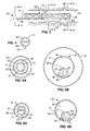
- FIG. 10A is a transverse cross sectional view of another embodiment having an expandable tubular member with a small profile wound configuration
- FIG. 10B is a transverse cross sectional view of the tubular member shown in FIG. 10A , illustrating the tubular member in the expanded unwound configuration.
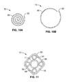
- FIG. 11 is a transverse cross-sectional view of another embodiment of an expandable tubular member comprising a plurality of inflatable balloons within an outer sheath.
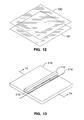
- FIG. 12 illustrates two sheets of polymeric film as the starting material for fabricating an expandable tubular member according to one exemplary embodiment of the invention.
- FIG. 13 is a perspective view of a fixture for heat fusion welding the film sheets in FIG. 12 .
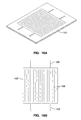
- FIG. 14 is an elevation view of the welding fixture in FIG. 13 showing the placement of the film sheets.
- FIG. 15 illustrates a cross section of two sheets of film welded by heat fusion.
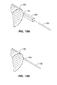
- FIG. 16A shows a typical pattern that would be used to weld the film sheets together to form the expandable tubular member.
- FIG. 16B illustrates the welded film sheets of FIG. 16A after trimming.
- FIG. 17 is a perspective view of a fixture used to configure the expandable tubular member into a tubular member.
- FIG. 18 is an elevation view of FIG. 17 showing the detail of the welding method.
- FIG. 19A shows a method of connecting the inflation tube to the expandable tubular member.
- FIG. 19B shows the inflation tube secured to the expandable tubular member.
- FIG. 20 illustrates the inflation tube entering the catheter shaft.
- FIG. 21 is a transverse cross sectional view of the catheter shaft shown in FIG. 20 , illustrating the position of the inflation tube.
- FIG. 22 illustrates the expandable tubular member in the inflated configuration.
- FIG. 23A shows a step of a folding process for the expandable tubular member shown in FIG. 22 .
- FIG. 23B shows another step of a folding process for the expandable tubular member shown in FIG. 22 .
- FIG. 23C shows another step of a folding process for the expandable tubular member in FIG. 22 .
- FIG. 23D shows another step of a folding process for the expandable tubular member shown in FIG. 22 .
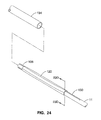
- FIG. 24 shows a sheath positioned over the folded expandable tubular member shown in FIG. 23D .
- FIG. 25 illustrates an enlarged view of a distal section of another embodiment having an expandable tubular member comprising a plurality of inflatable wall chambers and a balloon secured together to form the tubular member.
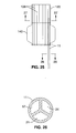
- FIG. 26 is a transverse cross sectional view, taken along line 26-26, of the catheter shaft shown in FIG. 25 .
- FIG. 27 is a transverse cross sectional view, taken along line 27-27, of the expandable tubular member shown in FIG. 25 .
- FIG. 28 illustrates an enlarged view of a distal section of another embodiment having an expandable tubular member comprising a plurality of inflatable wall chambers, wherein the tubular member has a conical shape.
- FIG. 29 is an elevational view of fused polymeric sheets used to form the tubular member, having straight seal lines forming the fluid communicating chambers.
- FIG. 30 is an elevational view of fused polymeric sheets used to form the tubular member, having curved seal lines forming the fluid-communicating chambers.
- FIG. 31 is a transverse cross-sectional view of a tubular member illustrated in FIG. 30 .
- FIG. 1 illustrates a catheter 10 which embodies features of the invention, generally comprising an elongated shaft 11 having a proximal end, a distal end, and at least one lumen 12 extending therein, a tubular member 13 on a distal section of the catheter shaft 11 and a radially expandable member 14 on the tubular member 13.
- Adapter 15 on the proximal end of the shaft provides access to the catheter lumen.
- FIG. 1 illustrates the tubular member and the radially expandable member in low profile, unexpanded configurations for entry into the patient's blood vessel.
- the radially expandable member 14 comprises an inflatable balloon.
- the balloon has proximal and distal ends secured to an outer surface of the tubular member 13, and an interior in fluid communication with an inflation lumen 21 (shown in FIG. 4 ) in the shaft 11.
- the balloon 14 can be formed of a variety of suitable materials typically used in the construction of catheter occlusion balloons, and in another embodiment is highly compliant and is formed of a material such as latex, polyisoprene, polyurethane, a thermoplastic elastomer such as C-Flex. In another embodiment, the balloon may be noncompliant or semi-compliant. While discussed below primarily in terms of a radially expandable member comprising a balloon, it should be understood that the radially expandable member may have a variety of suitable configurations.
- the tubular member 13 comprises braided filaments 16, such as wire, ribbon, and the like, having a sheath 17, and having a lumen or interior passageway 18 (shown in FIG. 5 ) therein.
- a pull line 19 having a distal portion secured to the tubular member is configured to be retracted or pulled proximally to radially expand the tubular member 13.
- the braided filaments 16 can reorient from a longer, smaller diameter configuration and a shorter, larger diameter configuration cause the tubular member to shorten, thereby radially expanding the tubular member 13.
- the sheath 17 is preferably an elastomeric polymer on the braided filaments.
- the sheath 17 can be on an inner or outer surface of the braided filaments, or the braided filaments can be completely or partially embedded within the sheath 17. In the embodiment in which the sheath is on a surface of the filaments, the sheath is preferably secured to a surface of the filaments as for example with adhesive or heat bonding.
- the braided filaments 16 can be formed of a variety of suitable materials such as metals or stiff polymers. A variety of suitable polymeric materials can be used to form the sheath 17. While discussed below primarily in terms of a tubular member comprising a braided tube, it should be understood that the tubular member may have a variety of suitable configurations.
- the dimensions of catheter 10 are determined largely by the size of the blood vessel(s) through which the catheter must pass, and the size of the blood vessel in which the catheter is deployed:
- the length of-the-tubular member 13 is typically about 50 to about 150 mm, preferably about 80 to about 120 mm.
- the tubular member 13 has an unexpanded outer diameter of the tubular member is typically about 1 to about 5 mm, preferably about 2 to about 4 mm, and a radially expanded outer diameter of about 40 to about 140 mm, preferably about 60 to about 120 mm.
- the radially expanded interior passageway 18 of the tubular member 13 is typically about 30 to about 130 mm, preferably about 50 to about 110 mm to provide sufficient perfusion.
- the interior passageway 18 of the tubular member 13 has a radially expanded inner diameter which is about 1000% to about 6000% larger than the unexpanded inner diameter of the passageway 18.
- the radially expandable member 14 has a length of about 10 to about 50 mm, preferably about 20 to about 40 mm.
- the expanded outer diameter of the radially expandable member 14 is about 10 to about 35 mm, preferably about 15 to about 30 mm.
- the tubular member dimensions given above should be understood to refer to the distal most (i.e., up-stream) or smaller diameter end of the conical member, unless otherwise stated.
- the radially expandable member 14 comprises the larger diameter end of a conically shaped tubular member
- the radially expandable member dimensions should be understood to refer to the proximal most (i.e., down-stream) or larger diameter end of the conical member.
- the shaft 11 has an outer diameter of about 1 to about 5 mm.
- the inflation lumen 21 has an inner diameter of about 0.02 to about 0.06 mm and the agent delivery lumen has an inner diameter of about 0.01 to about 0.04 mm.
- the length of the catheter is about 40 to about 100 cm, preferably about 60 to about 90 cm.
- FIG. 2 illustrates the tubular member 13 in the expanded configuration after retraction of the pull line 19.
- the exposed distal end of the shaft 11 is located proximal to the distal end of the expandable tubular member 13.
- the balloon 14 is in a non-expanded configuration.
- the section of the tubular member under the balloon is illustrated in dashed phantom lines.
- FIG. 3 illustrates schematically, the expanded tubular member 13 with the balloon 14 in the expanded configuration.
- the shaft has an inflation lumen 21 extending from the proximal end of the shaft 11 to an inflation port 22 (shown in FIG. 5A ) located on the shaft distal section, in fluid communication with the interior of the balloon.
- Arm 23 on adapter 15 (shown in FIG. 1 ) provides access to the inflation lumen 21, and is in fluid communication with a source of inflation fluid (not shown).
- the shaft also has an agent delivery lumen 24 extending from the proximal end to an agent delivery port 25 in the distal end of the shaft 11.
- Arm 26 on adapter 15 (shown in FIG. 1 ) provides access to the agent delivery lumen 24, and is in fluid communication with an agent source (not shown).
- the tubular member sheath 17 has an agent delivery opening 27 adjacent to the shaft agent delivery port 25, for providing a pathway for agent delivery from the lumen 24 to exterior to the tubular member 13.
- the inflation lumen 21 and agent delivery lumen 24 are side-by-side in a multilumen shaft 11, with inflation port 22 extending through a side wall of the shaft.
- agent delivery port 25 is preferably in a side wall of the shaft 11 distal section in fluid communication with the agent delivery lumen 24, however, alternatively, the agent delivery port 25 may be in the distal end of the shaft 11.
- FIG. 5B and FIG. 6B illustrate more specific embodiments where multilumen shaft 11 is attached to the inner wall of tubular member 13.
- Inflation lumen 21 is in fluid communication through inflation port 22 and agent delivery lumen 24 is in fluid communication with blood flow 33 through agent delivery port 25 and agent delivery opening 27.
- FIG. 3 illustrates the catheter 10 in a blood vessel 31, such as a descending aorta, of a patient, having branch vessels 32, such as the renal arteries, opening therein.
- the catheter 10 is introduced and advanced within the patient's blood vessel 31 in the low profile, unexpanded configuration illustrated in FIG. 1 .
- the agent delivery port 25 is positioned proximate to (up-stream or inline with) the one or more branch vessels 32, and the distal end of the tubular member is preferably up-stream of the one or more branch vessels 32.
- the tubular member is then expanded to the expanded configuration, and, preferably, thereafter the balloon 14 is radially expanded by directing inflation fluid into the balloon interior.
- the catheter is introduced into the femoral artery, as for example by the Seldinger technique, preferably slidingly over a guide wire (not shown), and advanced into the descending aorta 31.
- the shaft may be provided with a separate guide wire lumen, or the catheter may be advanced over a guide wire in agent delivery lumen 24 adapted to slidingly receive a guide wire.
- the catheter 10 may be advanced without the use of a guide wire.
- the agent delivery port 25 is positioned proximate to one or both renal arteries 32, as illustrated in FIG.
- tubular member 13 extends within the aorta 31 up-stream and down-stream of the renal arteries 32.
- the tubular member 13 is radially expanded by retracting pull line 19.
- the interior passageway 18 of the tubular member 13 separates blood flow through the blood vessel 31 into an outer blood flow stream 33 exterior to the tubular member 13, and an inner blood flow stream 34 within the interior passageway 18 of the tubular member 13.
- the balloon 14 is expanded by directing inflation fluid into the inflation lumen 21.
- the balloon 14 is expanded to an outer diameter which does not completely occlude the patient's aorta 31.
- the balloon expands into contact with the wall of the aorta 31, to an outer diameter which completely occludes the aorta 31 (not shown).
- Balloon 14 may have a length and elongated configuration configured to provide mechanical stability for and coaxial centering of the operative distal section of the catheter in the blood vessel 31.
- a stabilizing member (not shown) may be provided on an outer surface of the distal end of the tubular member 13, such as for example unfoldable arms which anchor the distal end of the catheter in the aorta 31 during delivery of agent.
- imaging modalities may be used to position the catheter in the desired location in the blood vessel, such as fluoroscopy, or ultrasound.
- radiopaque markers (not shown) on the shaft may be used in positioning the balloon 14 and agent delivery port 25 at the desired location in the blood vessel 31.
- a therapeutic or diagnostic agent (hereafter “agent”) is delivered to the renal arteries 32 by introducing the agent into the agent delivery lumen 24 in the shaft 11, and out the agent delivery port 25.
- An agent delivery opening 27 in the tubular member 13 adjacent to the agent delivery port 25 provides a pathway for agent delivery from lumen 24 to external to the tubular member 13.
- the agent delivery port 25 is up-steam of the renal arteries 32 and proximal to the distal end of the tubular member 13.
- the outer blood flow stream 33 has a relatively high concentration of agent and the inner blood flow stream 34 has a relatively low concentration or no agent.
- the balloon 14 in the expanded configuration restricts the flow of blood to decrease the blood flow exterior to the proximal portion of the tubular member 13 down-stream of the renal arteries 32 in comparison to the blood flow stream exterior to the distal portion of the tubular member 13 up-stream of the renal arteries 32.
- a relatively large amount of the agent delivered from the agent delivery port 25 is directed into the renal arteries 32, in comparison to the amount of agent which flows down-stream of the renal arteries 32 in the aorta 31.
- the outer blood flow stream is substantial.
- the cross-sectional area of the inner lumen 18 of the tubular member 13 is about 4% to about 64% of the blood vessel 31 (i.e., aorta) cross-sectional area, or about 4 mm to about 16 mm for a blood vessel 31 having a 20 mm inner diameter.
- the cross-sectional area of the wall of the tubular member 13 is not insignificant in relation to the cross- sectional area of the blood vessel 31. In the embodiment illustrated in FIG. 1 in which tubular member 13 comprises sheath 17 on a frame of filaments 16, this cross-sectional area is negligible. In another embodiments discussed below, such as the embodiments illustrated in FIGS.
- the cross-sectional area of the wall of the tubular member 13 may be about 2% to about 50%, more specifically about 5% to about 20%, of the cross-sectional area of a section of the blood vessel 31 located at the up-stream most end of the catheter 10.
- the aorta has multiple branch vessels in addition to the renal arteries which effect the total flow in the aorta at a given location therein.
- a percentage of the blood flow that enters the abdominal aorta, i.e., past the diaphragm, is delivered in the normal rest state of circulation to the celiac trunk, the superior and inferior mesenteric arteries, and the renal arteries.
- the flow segmentation created by the presence of the deployed catheter 10 is such that the blood flow in the outer blood flow stream 33 of a patient at rest is about 10% to about 90% of the total blood flow immediately up-stream of the up-stream or distal most end of the tubular member 13, i.e., of the total blood flow present in the section of the aorta 31 immediately adjacent to the renal arteries 32.
- the blood flow in the inner blood flow stream 34 of a patient at rest is about 10% to about 90% of the total blood flow immediately up-stream of the up-stream or distal most end of the tubular member 13.
- the flow in the outer blood flow stream 33 is , sufficient to provide adequate kidney function, although the flow required will vary depending upon factors such as the presence of drugs which increase flow or increase the ability of the tissue to withstand ischemic conditions.
- the catheter may be positioned and used- to deliver agent to the renal arteries individually, and specifically in anatomies having the renal arteries longitudinally displaced from one another.
- the flow of agent is then stopped.
- the tubular member 13 is contracted by urging the pull line 19, distally, and the balloon 14 is collapsed by removal of the inflation fluid, and the catheter removed from the patient.
- a variety of suitable radially expandable tubular members 13 may be used in the catheter 10 of the invention.
- FIG. 7 illustrates another embodiment of distal end of the catheter 10 in which the tubular member 13 comprises a self- expanding frame 40 having a sheath 41 thereon.
- catheter shaft 11 defines an inflation lumen 21 and an agent delivery lumen 24, and radially expandable member comprises a balloon 42 on an outer surface of sheath 41.
- the balloon 42 is shown as a transparent material. In the embodiment illustrated in FIG.
- catheter shaft 11 comprises a multilumen proximal shaft 43 defining proximal sections of the inflation lumen 21 and agent delivery lumen 24, a first distal tubular member 44 defining a distal section of inflation lumen 21 extending to inflation port 22, and a second distal tubular member 46 defining a distal section of agent delivery lumen 24 extending to agent delivery port 25.
- First tubular member 44 extends distally from the distal end of the proximal section of the inflation lumen 21 in the multilumen proximal shaft.
- second tubular member 45 extends distally from the distal end of the proximal section of the agent delivery lumen 24 in the multilumen proximal shaft.
- First and second tubular members 44,45 are typically formed of thin-walled polymeric material such as polyimide, with an inner diameter of about 0.002 inch to about 0.006 inch, and a wall thickness of about 0.0005 inch to about 0.002 inch.
- catheter shaft comprises an outer tubular member with first and second inner tubular members defining inflation lumen and agent delivery lumen, respectively, extending within the outer member and out the distal end thereof.
- the agent delivery lumen 24 extends to a location proximal to the distal end of the tubular member 13 and distal to the balloon.
- One or more agent delivery ports 25 are provided in a distal section of the agent delivery lumens, as discussed above in relation to the embodiment of FIG. 1 . In other embodiments, one or more additional agent delivery lumens may be provided.
- the frame 40 comprises longitudinally extending filaments or struts, such as wires, joined together at the proximal and distal ends thereof.
- frame 40 is formed of high strength metal, such as stainless steel, nickel-titanium alloy, and titanium.
- the filaments typically have a round transverse cross section, with a diameter of about 0.006 inch to about 0.016 inch, or a rectangular transverse cross section with a thickness of about 0.001 inch to about 0.006 inch and a width of about 0.006 inch to about 0.016 inch.
- Sheath 41 is similar to sheath 17 discussed in relation to the embodiment of FIG.
- the frame 40 is radially collapsible to a low profile configuration with the sheath 41 in a folded or pleated compact configuration for advancement within the patient's blood vessel.
- a restraining member which applies a radially compressive force, which holds the frame in the collapsed smaller diameter configuration, is removed so that the frame expands.
- the frame may be held in the collapsed smaller diameter configuration by a variety of suitable restraining members such as a delivery catheter or removable outer sheath.
- the frame is deformed into the smaller diameter configuration within the lumen of a delivery catheter 46, and then expanded in the blood vessel lumen by longitudinally displacing the frame out the distal end of the delivery catheter 46 to thereby remove the radially compressive force of the delivery catheter 46.
- a pull line similar to pull line 19 discussed above in relation to the embodiment of FIG. 1 may be provided to apply additional radially expanding force to the filaments to supplement their inherent spring force, and is preferably provided in the embodiments having a radially expandable member 14 comprising an inflatable balloon where inflation of the balloon creates a radially compressive force on the tubular member 13.
- balloon 42 is inflated into contact with the aorta wall 31 to an outer diameter which completely occludes the outer blood flow stream downstream of the renal arteries 32.
- the outer blood flow stream is directed into the branch vessels 32.
- the balloon may be configured to inflate to an outer diameter which does not completely occlude the downstream outer blood flow stream, as discussed above in relation to the embodiment of FIG. 3 .
- FIG. 8 illustrates another embodiment sharing certain similarities with the embodiment shown in FIG. 7 except that the balloon member 14 is replaced with a radially enlarged section 47 of the tubular member 13.
- the frame 40, with sheath 41 thereon, forming the tubular member 13 does not have a uniform outer diameter, but instead radially expands from a collapsed configuration to define a smaller diameter section 48 defining tubular member 13, and a larger diameter section 49 defining a larger radial expandable member 14.
- FIG. 9A and 9B and FIG. 10A and 10B illustrate transverse cross sectional views of another embodiment in which the tubular member 13 comprises a sheet 50 configured to unwind from a wound low profile to an unwound radially expanded configuration to thereby radially expand the interior passageway 18 of the tubular member 13.
- FIG. 9A illustrates an embodiment in which the sheet 50 has a section wound back and forth into a plurality of folds 51.
- a restraining member such as an outer sheath or delivery catheter is removed so that the sheet 50 unfolds as illustrated in FIG. 9B .
- the sheet section configured to be folded is preferably a thinner walled or otherwise more flexible than the section of the sheet which is not folded.
- FIG. 9A illustrates an embodiment in which the sheet 50 has a section wound back and forth into a plurality of folds 51.
- a restraining member such as an outer sheath or delivery catheter is removed so that the sheet 50 unfolds as illustrated in FIG. 9B .
- the sheet 50 is wound around itself into a rolled-up configuration having a free edge 52 extending the length of the sheet 50, which unrolls to the radially expanded configuration illustrated in FIG. 10B .
- a variety of suitable unfurling or uncoiling configurations may be used in a tubular member which is radially expandable in accordance with the invention including a rolled awning-type mechanism, and the like.
- FIG. 11 illustrates a transverse cross sectional view of another embodiment in which the tubular member 13 comprises a plurality of inflatable balloons 54 within an outer sheath 55.
- the balloons 54 can be inflated from a non-inflated low profile configuration to an inflated configuration.
- inner passageway 18 is defined between the inflated balloons in part by the sheath 55.
- three or more balloons 54 are provided to in part define the inner passageway 18.
- Balloons 54 are preferably formed of a noncompliant material such as PET, or a compliant material such as polyethylene having reinforcing members such as wire members. Although four, cylindrical balloons 54 are illustrated in FIG.
- balloons having outer channels such as a spiraled balloon defining an outer spirally extending blood flow channel, similar in many respects to perfusion balloons for dilatation.
- An inflation lumen is provided in the catheter shaft 11 in fluid communication with balloons 54.
- FIG. 12 through FIG. 21 illustrate a fabrication method according to one exemplary embodiment of the expandable tubular member.
- two sheets of a polymeric film, sheet 100 and sheet 101 are configured for seam welding.
- suitable materials can be used to form the sheets including polyolefins, low density polyethylene, polyurethane, polyamides, nylon, polyether block amide, polyethylene terephthalate, and other thermoplastics.
- FIG. 13 and FIG. 14 illustrate a fixture for heat-fused welding sheets 100 and 101.
- Base 110 of the fixture provides a surface for press plate 112 to compress sheets 100 and 101 on a hot wire 114 in base 110.
- Press plate 112 has silicone rubber gasket 116 for contact with the film.
- PTFE coated sheet 118 is placed over hot wire 114 to prevent sheet 101 from sticking to hot wire 114.
- FIG. 15 illustrates a cross section of a typical heat-fused weld of sheets 100 and 101.
- FIG. 16A shows a typical pattern of heat fused welds where sheets 100 and 101 are welded together with a pattern of seal lines to form inflatable member 102.
- seal lines are shown in parallel, such a highly beneficial embodiment is not intended to be limiting to the various broad aspects of the present embodiment and other arrangements are contemplated to suit a particular need.
- the seal lines forming the wall chambers 108 do not extend to the proximal most and/or distal most end of the tubular member, so that the wall chambers are in fluid communication with one another.
- the seal lines defining the wall chambers 108 of the tubular member 102 extend in parallel lines in inflatable member 102.
- FIG. 16B illustrates inflatable member 102 following trimming.
- One or more inflation tabs 104 are formed and have fluid connection to the wall chambers 108 in inflatable member 102.
- One or more attachment tabs 106 are formed and are closed to the wall chambers 108.
- FIG. 16B illustrates one configuration of inflation tabs 104 and attachment tabs 106 but configurations may be formed and positioned at the proximal or distal ends of inflatable member 102.
- FIG. 17 is a perspective view and FIG. 18 is an end view of a wrapping and sealing fixture for inflatable member 102.
- Sealing fixture 122 has curved depression 124 and mandible 126 which conforms to curved depression 124.
- Inflatable member 102 is then wrapped into a cylindrical shape and the edges secured together with a heat-fused weld using hot wire 128 to form tubular member 120 which is collapsible and foldable into a compact configuration for advancement within the blood vessel.
- the seal lines defining the wall chambers of the tubular member 120 are parallel along the cylindrical wall of tubular member 120, but again while this is particularly beneficial, other configurations may be formed.
- FIG. 19A and FIG. 19B illustrate the connection of inflation tube 130 to tubular member 120.
- Inflation tube 130 is inserted in inflation tabs 104 to be fluidly connected with the walled chambers 108 in tubular member 120.
- Adapting tube 132 is placed over inflation tab 104 and inflation tube 130 to provide a sealed connection.
- Adapting tube 132 can be a heat activated shrink tubing consisting of a heat-recoverable polyolefin, polyester, or other suitable material.
- FIG. 20 is a side view and FIG. 21 is a transverse cross section of FIG. 20 illustrating the configuration of inflation tube 130 entering catheter shaft 11.
- Inflation tube 130 enters an inner lumen of catheter 11 where it is sealed with a potting compound such as epoxy or sealed with heat fusion.
- FIG. 22 illustrates an enlarged distal end of one embodiment having a tubular member 120 formed of a plurality of inflatable fluid-communicating wall chambers 108, in which one or more inflation tubes 130 extend from a port in the sidewall of shaft 11 in communication with an inflation lumen in shaft 11 to the distal and/or proximal end of the tubular member.
- the inflation tubes 130 are in fluid communication with the wall chambers of the tubular member 120, and are used for delivering inflation fluid into the wall chambers 108 to thereby inflate the tubular member 120.
- inflation tube 130 is secured to tubular member 120 by adapting tube 132 at the proximal end of tubular member 120.
- Attachment tabs 106 secure the distal end of tubular member 120 to the distal end of catheter shaft 11.
- FIG. 23A through FIG. 24 illustrate a method by which tubular member 120 can be folded into a compact configuration for insertion.
- FIG. 23A is an end view with catheter shaft 11 in the center connected to tubular member 120 by inflation tubes 130.
- tubular member 120 is folded into 4 wings about catheter shaft 11.
- FIG. 23C the wings of tubular member 120 are wrapped in pinwheel fashion and compacted in FIG. 23D .
- FIG. 24 illustrates compacted tubular member 120 enclosed in a tight sheath 134.
- the sheath may be formed of PTFE or other suitable material. During deployment, the sheath may be removed from the tubular member 120 by a pull wire (not shown) or other suitable method. The sheath may also be a delivery catheter.
- FIG. 25 through FIG. 27 illustrate another embodiment wherein tubular member 120 comprises a plurality of wall chambers 108 joined together and attached to catheter shaft 11.
- the wall chambers 108 can be bonded together using a variety of suitable methods including an adhesive, heat fusion bonding, or solvent bonding such as with hexa-fluoro isopropanol (HFIP) for PET balloons.
- HFIP hexa-fluoro isopropanol
- the radially expandable member 140 which is an inflatable balloon is shown as a transparent material.
- the multilumen shaft 11 defines an inflation lumen 21 in fluid communication with balloon 140 on an outer surface of the tubular member 120, (Similar to FIG.
- tubular member 120 is formed as a cylinder to thereby define the tubular member interior passageway 18.
- Catheter shaft 11 is inserted in a walled chamber 108.
- Agent delivery opening 27 in walled chamber 108 is adjacent to the shaft agent delivery port 25 and provides a pathway for agent delivery from the lumen 24 to exterior to the tubular member 120.
- the tubular member 120 can be deflated and compressed, folded, pleated or otherwise reduced in size for introduction and advancement within the patient's blood vessel as shown in FIG. 23A through FIG. 24 .
- the pressure required to inflate the balloon 140 is significantly lower than the pressure used to inflate the walled chambers 108 forming the tubular member 120, so that inflation of the balloon 140 does not deform the tubular member 120.
- FIG. 28 illustrates the enlarged distal end of another embodiment having a tubular member 150 formed of a plurality of inflatable fluid-communicating wall chambers 108 in the shape of a cone.
- One or more inflation tubes 130 extend from a port in the sidewall of shaft 11 in communication with inflation lumen 57 (shown in FIG. 26 ) to the distal and/or proximal end of the tubular member 150.
- the inflation tubes 130 are in fluid communication with the wall chambers 108 of the tubular member 150, and are used for delivering inflation fluid into the wall chambers 108 to thereby inflate the tubular member 150.
- FIG. 28 illustrates the enlarged distal end of another embodiment having a tubular member 150 formed of a plurality of inflatable fluid-communicating wall chambers 108 in the shape of a cone.
- One or more inflation tubes 130 extend from a port in the sidewall of shaft 11 in communication with inflation lumen 57 (shown in FIG. 26 ) to the distal and/or proximal end of the
- inflation tube 130 is secured to tubular member 150 by an adapting tube 132 at the proximal end of tubular member 150 as also shown in FIG. 22 .
- One or more agent delivery tubes 136 extend from a port in the shaft 11 in fluid communication with agent delivery lumen 24 (shown in FIG. 26 ) and into wall chamber 108 of the tubular member 150.
- Agent delivery port 25 at the distal end of the agent delivery tube 136 extends to and in fluid communication with an agent delivery opening 27 in a wall defining wall chamber 108 of the tubular member 150 as shown in FIG. 27 .
- the section of the agent delivery tube 136 located within wall chamber 108 of the tubular member 150 is illustrated in phantom in FIG. 28 .
- one or more wall chambers 108 of the tubular member 150 can be used for agent delivery rather than inflation of tubular member 150.
- tubular member 150 is conical.
- the conical tubular member 150 tapers from a large diameter proximal end 152 to a smaller diameter distal end 154, so that the large diameter distal end 152 of tubular member 150 replaces the radially expandable balloon member 140 shown in FIG. 25 . Consequently, a separate radially expandable balloon member is not required.
- FIG. 29 illustrates an elevational view of inflatable member 103 for forming another embodiment of a tubular member (not shown) in which the wall chambers 160 are welded in a serpentine pattern 162.
- Wall chambers 160 are open at one end and are fluidly connected.
- Agent delivery tube 136 with agent delivery opening 27 is shown positioned within a walled chamber 160 and secured with adapting tube 132.
- Inflation tabs 104 are connected similar to the method described in FIG. 16B .
- FIG. 30 illustrates an elevational view of inflatable member 105 for forming another embodiment of a tubular member 164, (shown in FIG. 31 ) in which the wall chambers 166 are defined by curvilinear seal lines 168 to form interleaved cells, so that a more complete occlusion is provided by the tubular member 164.
- FIG. 31 illustrates a transverse cross-sectional view of an expanded tubular member 164 with wall chambers 166 formed from the curvilinear seal lines 168.
- the catheter of the invention could be used to deliver agent to branch vessels other than renal arteries, or to deliver to sites other than branch vessels, as for example where the catheter is used to deliver an agent to the wall defining the body lumen in which the catheter is positioned, such as a bile duct, ureter, and the like.
- an agent to the wall defining the body lumen in which the catheter is positioned, such as a bile duct, ureter, and the like.
- certain features may be shown or discussed in relation to a particular embodiment, such individual features may be used on-the various other embodiments of the invention.
Abstract
Description
- Not Applicable
- Not Applicable
- Not Applicable
- This invention relates to the field of medical devices, and more particularly to a catheter configured for drug delivery.
- Acute renal failure ("ARF") is an abrupt decrease in the kidney's ability to excrete waste from a patient's blood. This change in kidney function may be attributable to many causes. A traumatic event, such as hemorrhage, gastrointestinal fluid loss, or renal fluid loss without proper fluid replacement may cause the patient to go into ARF. Patients may also become vulnerable to ARF after receiving anesthesia, surgery, or α-adrenergic agonists because of related systemic or renal vasoconstriction. Additionally, systemic vasodilation caused by anaphylaxis, and antihypertensive drugs, sepsis or drug overdose may also cause ARF because the body's natural defense is to shut down, i.e., vasoconstrict, non-essential organs such as the kidneys. Reduced cardiac output caused by cardiogenic shock, congestive heart failure, pericardial tamponade or massive pulmonary embolism creates an excess of fluid in the body, which can exacerbate congestive heart failure. For example, a reduction in blood flow and blood pressure in the kidneys due to reduced cardiac output can in turn result in the retention of excess fluid in the patient's body, leading, for example, to pulmonary and systemic edema.
- Previously known methods of treating- ARF, or of treating acute renal insufficiency associated with congestive heart failure ("CHF"), involve administering drugs. However, many of these drugs, when administered in systemic doses, have undesirable side effects. Additionally, many of these drugs would not be helpful in treating other causes of ARF. While a septic shock patient with profound systemic vasodilation often has concomitant severe renal vasoconstriction, administering vasodilators to dilate the renal artery to a patient suffering from systemic vasodilation would compound the vasodilation system wide. In addition, for patients with severe CHF (e.g. those awaiting heart transplant), mechanical methods, such as hemodialysis or left ventricular assist devices, may be implemented. Mechanical treatments, such as hemodialysis, however, generally have not been used for long-term management of CHF. Such mechanical treatments would also not be help for patients with strong hearts suffering from ARF.
- Intra-aortic balloon pumps (IABPs) have been suggested for use in diverting blood flow into branch arteries. One such technique involves placing an IABP in the abdominal aorta so that the balloon is situated slightly below (proximal to) the branch arteries. The balloon is selectively inflated and deflated in a counterpulsation mode so that increased pressure distal to the balloon directs a greater portion of blood flow into the branch arteries. Although the IABP method of counterpulsation may be effective for increasing coronary perfusion, it would not extend well to the renal arteries.
- It would be a significant advance to provide an intra-aortic catheter for improved delivery of agents to a branch vessel such as a renal artery.
- The invention is directed to a catheter controlling the flow of blood in a major blood vessel to a branch blood vessel, and particularly for delivering a therapeutic or diagnostic agent to the branch blood vessel with the blood flow thereto. The catheter generally comprises an elongated shaft, an expandable tubular member on a distal section of the shaft, and a radially expandable member on the expandable tubular member. Preferably, the elongated shaft has at least one lumen in fluid communication with an agent delivery port in a distal section of the shaft. The expandable tubular member is configured to extend within a major blood vessel up-stream and down-stream of a branch vessel, and as an interior passageway which is radially expandable within the major blood vessel to separate blood flow through the major blood vessel into an outer blood flow stream exterior to the tubular member and an inner blood flow stream within the interior passageway of the tubular member. Thus, the expandable tubular member provides a perfusion passageway in the major blood vessel. The radially expandable member is located down-stream of the agent delivery port and is positioned down-stream of the branch artery, and has an expanded configuration with an outer diameter larger than an outer diameter of the expanded tubular member located up-stream thereto. In the expanded configuration, the radially expandable member is configured constrict blood flow past an outer surface of the radially expandable member and direct at least part of the blood flow in the outer blood flow stream into the branch vessel, which, consequently, decreases the blood flow in the outer blood flow stream down- stream of the branch vessel. The catheter of the invention provides for delivery of an agent to a side branch vessel of a major vessel, and continuous perfusion of the major blood vessel. Another aspect of the invention is directed to methods of delivering a therapeutic or diagnostic agent to one or both kidney's of a patient.
- The term proximal should be understood to mean locations on the catheter relatively closer to the operator during use of the catheter, and the term distal should be understood to mean locations on the catheter relatively further away from the operator during use of the catheter. The term up-stream should be understood to mean locations on the catheter relatively further upstream in the blood flow within the blood vessel, when the catheter is in place in the patient's blood vessel. The term down-stream should be understood to mean locations on the catheter relatively further down-stream in the blood flow within the blood vessel, when the catheter is in place in the patient's blood vessel.
- The tubular member interior passageway defines a perfusion or blood pass-through lumen. The interior passageway is radially expandable, So that the tubular member can be expanded from an unexpanded configuration providing a low profile for insertion and advancement of the catheter within the patient's blood vessel, to an expanded configuration providing a desired level of perfusion within the blood vessel. The expanded interior passageway of the tubular member is sufficiently large to avoid or limit detrimental effects of occluding the blood vessel, and specifically, in one embodiment, the effects of infrarenal aortic occlusion. However, in addition to the inner blood flow stream within the inner lumen of the tubular member, the tubular member has an outer diameter in the expanded configuration along at least a section thereof which is configured to allow for an outer blood flow stream exterior to the tubular member which is at least in part directed or flowing to the branch vessel. As a result, the catheter can be used to deliver an agent from the agent delivery port into the outer blood flow stream and to the patient's branch vessel.
- The tubular member can be expanded by a variety of suitable methods. In one embodiment, the tubular member is self-expanding. For example, a radially collapsed tubular member is expanded by release of a radially compressive force, as for example, by removal of a sheath of guide catheter from around the tubular member. Similarly, a wound or folded tubular member is expanded by allowing the member to unwind or unfold into the expanded tubular configuration. In another embodiment, the tubular member comprises a cylindrical inflatable member formed of a plurality of fluid-communicating wall chambers, which is inflated by directing inflation fluid into the wall chambers. In another embodiment, the tubular member has a braided structure, which is expanded by retracting a pull line to thereby shorten the length of the braided structure. In another embodiment, the tubular member is a balloon, which is expanded by directing inflation fluid into an wall chamber of the tubular member.
- The radially expandable member is on a proximal or down-stream section of the tubular member, and is configured to restrict blood flow in the blood vessel. The radially expandable member has an expanded configuration with a larger outer diameter than the expanded tubular member. The radially expandable member may be a separate member secured to the tubular member as for example, where the radially expandable member is a balloon secured to an outer surface of a tubular member. Alternatively, the radially expandable member may be an integral part of the tubular member so that the tubular member and radially expandable member are a one-piece unit of the catheter, as for example, where the tubular member is a frame or braided structure having a sheath thereon and the radially expandable member is a radially enlarged section of the tubular member which expands as the tubular member expands, or where the tubular member is cone shaped and the radially expandable member is the largest diameter section of the cone shaped tubular member.
- In the expanded configuration, the radially enlarged member is configured to decrease blood flow in the outer blood flow stream down-stream of the branch vessel. Thus, a relatively large concentration of agent is delivered into the branch vessel from the agent delivery port, in comparison to the amount of agent allowed to flow through the blood vessel down-stream of the branch vessel. In one embodiment, the radially expandable member has an expanded outer diameter configured to partially occlude, i.e., restrict but not completely block, the outer blood flow stream in the blood vessel. Thus, a portion of the outer blood flow through the blood vessel is allowed to flow around and down-stream of an outer surface of the radially expandable member. However, in another embodiment, the radially expandable member has an outer diameter configured to contact a wall of the blood vessel and thereby occlude the outer blood flow stream in the blood vessel down-stream of the branch vessel.
- Thus, the catheter of the invention separates the blood flow through the blood vessel into an outer blood flow stream directed in part into the branch vessel having a relatively high concentration of agent, and an inner blood flow stream. The end of the tubular member positioned up-stream of the branch vessel is located up-stream of agent delivery port in the shaft, so that the inner blood flow stream within the tubular member has a relatively low amount of or no agent. Moreover, with the radially expandable member in the expanded configuration, the blood flow exterior to the tubular member down-stream of the branch vessel is decreased in comparison to the blood flow stream exterior to the tubular member up-stream of the branch vessel. As a result, the amount of agent in the outer blood flow stream directed into the branch vessel is improved.
- The catheter of the invention can be used to deliver a variety of therapeutic or diagnostic agents to the patient's blood vessel. In one embodiment, vasoactive and/or renal protective agents such as Papaverine, are delivered to the renal arteries for treatment of ARF and fluid overload. Other preferred agents include Calcium-channel blockers such as nifedipine or verapamil, and fenoldapam, a dopamine DA1 agonist. The tubular member inner lumen providing a perfusion pathway allows the catheter to be in place in the patient's blood vessel for extended periods of treatment. The period of treatment will depend on the application and the agent, but is typically about 2 to about 72 hours, preferably about 4 to about 8 hours.
- It is to be appreciated, therefore, that another aspect of the invention locally delivers these drugs bilaterally into each side of the renal system via 2 renal arteries perfusing each kidney respectively. While the specific devices described are beneficial modes of such aspect, other devices, systems or specific delivery methods are contemplated.
- The catheter of the invention provides improved agent delivery to a branch vessel with continuous perfusion of the major blood vessel due to the relatively large perfusion lumen in the tubular member. Thus, possible detrimental effects of infrarenal aortic occlusion are reduced or prevented. Moreover, the catheter of the invention provides a relatively large concentration of agent to the renal arteries with little loss of blood flow through the aorta to the lower limbs. The catheter configured for intra-aortic delivery of an agent provides for relatively quick, intraluminal placement of the catheter.
- Another aspect of the invention is a method for enhancing renal function in a patient, where a portion of aortic blood flowing within an abdominal aorta is diverted along a flow path into the renal arteries via a number of ostia placed along the abdominal aorta wall. A volume of fluid agent adapted to enhance renal function is injected into the diverted flow path and is delivered into the renal arteries via the diverted flow path. More particularly, the injected fluid agent is delivered simultaneously and only into the renal arteries. A further aspect is to allow a second portion of aortic blood to flow along a second flow path downstream into downstream circulation while diverting the first portion of aortic blood into the renal arteries. A further beneficial embodiment is to use a fluid delivery port to deliver a volume of fluid agent into the diverted flow path. In a variation of this embodiment, the flow diverter generally comprises an adjustable wall and in a more particular embodiment, a tubular member.
- Another aspect of the invention generally comprises a bi-lateral renal drug delivery system adapted to deliver a volume of fluid agent to each renal artery simultaneously and thereby perfusing each kidney.
- Another aspect of the invention is a method for enhancing renal function in a patient including: diverting a portion of aortic blood flowing into a location within an abdominal aorta to flow along a diverted flow path substantially only into a plurality of renal arteries via a plurality of respective ostia having unique respective locations along the abdominal aorta wall; and injecting a volume of fluid agent into the diverted flow path within the abdominal aorta at the location. Further to this method, the injected fluid agent is delivered substantially only into the plurality of renal arteries via the diverted flow path into their respective ostia. Moreover, the fluid agent being delivered into the plurality of renal arteries is adapted to enhance renal function.
- One mode of this aspect further includes locally delivering a volume of diuretic fluid agent into the plurality of renal arteries. In one embodiment of this mode, the diuretic is Furosemide or an analog or derivative thereof. In another embodiment, it is Thiazide or an analog or derivative thereof.
- According to another mode, the local delivery of fluid agent into the plurality of renal arteries includes locally delivering a volume of vasopressor into the plurality of renal arteries. In one embodiment of this mode, the vasopressor is Dopamine or an analog or derivative thereof.
- In another mode of this method, the fluid agent is a vasodilator.
- In another mode, the fluid agent is a vasoactive fluid agent.
- In another mode, the fluid agent is Papaverine.
- In another mode, the fluid agent is an analog or derivative of Papaverine.
- In another mode, the fluid agent is a Calcium-channel blocker.
- In another mode, the fluid agent is Nifedipine.
- In another mode, the fluid agent is an analog or derivative of Nifedipine.
- In another mode, the fluid agent is Verapamil.
- In another mode, the fluid agent is an analog or derivative of Verapamil.
- In another mode, the fluid agent is Fenoldapam.
- In another mode, the fluid agent is an analog or derivative of Fenoldapam into the plurality of renal arteries.
- In another mode, the fluid agent is a dopamine DA1 agonist.
- According to still a further mode of the local renal drug delivery method, the fluid agent is delivered into the plurality of renal arteries for between about 2 and about 72 hours. In one embodiment, the fluid agent is delivered into the plurality of renal arteries for between about 4 and about 8 hours.
- In still a further highly beneficial mode, the injected fluid agent is delivered substantially only into the plurality of renal arteries via their respective ostia simultaneously.
- In another mode, the method further includes allowing a second portion of aortic blood to flow along a second flow path downstream across the plurality of renal artery ostia and into downstream circulation. This is done while diverting the portion of aortic blood into diverted flow path into the renal arteries and also while delivering the fluid agent into the plurality of renal arteries via the diverted flow path.
- Another aspect of the invention is a system for enhancing renal function in a patient that includes a delivery catheter, a flow diverter, and a source of fluid agent. The delivery catheter has a proximal end portion and a distal end portion with a fluid delivery port. The flow diverter is located along the distal end portion. The delivery catheter is adapted to couple to the source of fluid agent, and also to position the distal end portion at a location within an abdominal aorta associated with a plurality of renal artery ostia having unique respective positions along the abdominal aorta wall. The flow diverter at the location is adapted to divert a portion of aortic blood flow along a diverted flow path substantially only into the plurality of renal arteries via their respective ostia. Moreover, the fluid delivery port is positioned relative to the flow diverter so as to inject a volume of the fluid agent from the source into the diverted flow path. The fluid agent is adapted to enhance renal function.
- According to one mode of this aspect, the fluid agent is a diuretic. In one embodiment, the diuretic is Furosemide or an analog or derivative thereof. In another embodiment, it is Thiazide or an analog or derivative thereof.
- According to another mode, the fluid agent is a vasopressor. In one embodiment, the vasopressor is Dopamine or an analog or derivative thereof.
- According to still another mode, the fluid agent is a vasodilator.
- According to another mode, the fluid agent is a vasoactive agent.
- According to another mode, the fluid agent is Papaverine.
- According to another mode, the fluid agent is an analog or derivative of Papaverine.
- According to another mode, the fluid agent is a Calcium-channel blocker.
- According to another mode, the fluid agent is Nifedipine.
- According to another mode, the fluid agent is an analog or derivative of Nifedipine.
- According to another mode, the fluid agent is Verapamil.
- According to another mode, the fluid agent is an analog or derivative of Verapamil.
- According to another mode, the fluid agent is Fenoldapam.
- According to another mode, the fluid agent is an analog or derivative of Fenoldapam.
- According to another mode, the fluid agent is a dopamine DA1 agonist.
- According to still a further mode, the delivery catheter is further adapted to allow a second portion of aortic blood to flow downstream across the plurality of renal artery ostia and into downstream circulation. This is accomplished while the flow diverter is adjusted to divert the portion of aortic blood flow along the diverted flow path, and while the fluid agent is injected into the diverted flow path.
- According to yet another mode, the flow diverter includes an adjustable wall that is adjustable between a first position and a second position. In the first position the flow diverter is adapted to be delivered to the location within the abdominal aorta. In the second position the adjustable wall is adapted to divert the portion of aortic blood flow along the diverted flow path. In one embodiment, the adjustable wall is a tubular member, such that the first position is characterized as a radially collapsed condition for the tubular member, and the second position is characterized as a radially expanded condition for the tubular member. In one variation of this embodiment, the tubular member has a conical shape. In another variation, the tubular member has a frustroconical shape. In another variation, the tubular member is an inflatable member. In still a further variation, the tubular member is adapted to radially engage the abdominal aorta wall in the radially expanded condition at the location.
- Another aspect of the invention is a system for treating a renal system in a patient with a renal drug delivery system coupled to a volume of fluid agent. The renal drug delivery system is adapted to deliver the volume of fluid agent bilaterally to each of two renal arteries simultaneously. The fluid agent is Papaverine, a Calcium-channel blocker, Nifedipine, Verapamil, Fenoldapam, or a dopamine DA1 agonist. In further modes, the fluid agent includes a combination or blend of two or more of these agents. In another mode, the fluid agent includes an analog or derivative of one or more of these agents.
- In one particular mode, the agent is Papaverine.
- In another particular mode, the agent is a Calcium-channel blocker.
- In another particular mode, the agent is Nifedipine.
- In another particular mode, the agent is Verapamil.
- In another particular mode, the agent is Fenoldapam.
- In another particular mode, the agent is a dopamine DA1 agonist.
- Another aspect of the invention is a system for treating a renal system in a patient with a local renal drug delivery system coupled to a volume of fluid agent. The renal drug delivery system is adapted to deliver the volume of fluid agent bilaterally to each of two renal arteries simultaneously. The fluid agent includes an analog or derivative of Papaverine, Nifedipine, Verapamil, or Fenoldapam. In further modes, the fluid agent may include a combination or blend of two or more of these agents.
- Another aspect of the invention is a method for treating a renal system in a patient that includes locally delivering a volume of fluid agent bilaterally into each of two renal arteries perfusing each of two kidneys substantially simultaneously. Further to this method, the fluid agent being bilaterally delivered into the renal arteries includes Papaverine, a Calcium-channel blocker, Nifedipine, Verapamil, Fenoldapam, or a dopamine DA1 agonist. In further modes, the fluid agent may include a combination or blend of two or more of these agents. In another mode, the fluid agent includes an analog or derivative of one or more of these agents.
- Another aspect of the invention is a method for treating a renal system in a patient that includes locally delivering a volume of fluid agent bilaterally into each of two renal arteries perfusing each of two kidneys substantially simultaneously. Further to this method, the fluid agent being bilaterally delivered into the renal arteries is an analog or derivative of Papaverine, a Calcium-channel blocker, Nifedipine, Verapamil, Fenoldapam, or a dopamine DA1 agonist. In further modes, the fluid agent may include a combination or blend of two or more of these agents. In another mode, the fluid agent includes an analog or derivative of one or more of these agents.
- It is to be appreciated that each of the various aspects, modes, embodiments, variations, and features herein shown and described is considered independently beneficial, either in the context of its utility for forming combinations such as for example with other elements otherwise herein described, or otherwise in its own regard, and therefore is not intended to be necessarily limited by combinations with such other elements unless specifically required. Notwithstanding the foregoing, such combinations of elements as herein shown and described are nevertheless also considered independently valuable, as would be apparent to one of ordinary skill based upon the totality of this disclosure and by reference to other available information.
- These and other advantages of the invention will become more apparent from the following detailed description of the invention and the accompanying exemplary drawings.
-
FIG. 1 is an elevational view, partially in section, of a catheter which embodies features of the invention, illustrating the expandable tubular member and balloon in an unexpanded configuration. -
FIG. 2 is an enlarged view, partially in phantom, of a distal section of the catheter shown inFIG. 1 , with the tubular member in the expanded configuration. -
FIG. 3 is an enlarged view, partially in phantom, of a distal section of the catheter shown inFIG. 2 , illustrating the catheter in the patient's descending aorta proximate the renal arteries, with the balloon in the inflated configuration. -
FIG. 4 is a transverse cross sectional view of the balloon shown inFIG. 3 , taken along line 4-4. -
FIG. 5A is a transverse cross sectional view of the balloon shown inFIG. 3 , taken along line 5-5. -
FIG. 5B is an another embodiment of a transverse cross sectional view of the balloon shown inFIG. 3 -
FIG. 6A is a transverse cross sectional view of the balloon shown inFIG. 3 , taken along line 6-6. -
FIG. 6B is another embodiment of a transverse cross sectional view of the balloon shown inFIG. 3 , taken along line 6-6. -
FIG. 7 is an enlarged view, partially in phantom, of a distal section of another embodiment having an expandable tubular member comprising a sheath covered collapsible frame. -
FIG. 8 is an enlarged view, partially in phantom, of a distal section of an another embodiment having a radially expandable member comprising a radially enlarged section of the expandable tubular member. -
FIG. 9A is a transverse cross sectional view of another embodiment having an expandable tubular member with a small profile wrapped configuration. -
FIG. 9B is a transverse cross sectional view of the tubular member shown InFIG. 9A , illustrating the tubular member in the expanded unwrapped configuration. -
FIG. 10A is a transverse cross sectional view of another embodiment having an expandable tubular member with a small profile wound configuration -
FIG. 10B is a transverse cross sectional view of the tubular member shown inFIG. 10A , illustrating the tubular member in the expanded unwound configuration. -
FIG. 11 is a transverse cross-sectional view of another embodiment of an expandable tubular member comprising a plurality of inflatable balloons within an outer sheath. -
FIG. 12 illustrates two sheets of polymeric film as the starting material for fabricating an expandable tubular member according to one exemplary embodiment of the invention. -
FIG. 13 is a perspective view of a fixture for heat fusion welding the film sheets inFIG. 12 . -
FIG. 14 is an elevation view of the welding fixture inFIG. 13 showing the placement of the film sheets. -
FIG. 15 illustrates a cross section of two sheets of film welded by heat fusion. -
FIG. 16A shows a typical pattern that would be used to weld the film sheets together to form the expandable tubular member. -
FIG. 16B illustrates the welded film sheets ofFIG. 16A after trimming. -
FIG. 17 is a perspective view of a fixture used to configure the expandable tubular member into a tubular member. -
FIG. 18 is an elevation view ofFIG. 17 showing the detail of the welding method. -
FIG. 19A shows a method of connecting the inflation tube to the expandable tubular member. -
FIG. 19B shows the inflation tube secured to the expandable tubular member. -
FIG. 20 illustrates the inflation tube entering the catheter shaft. -
FIG. 21 is a transverse cross sectional view of the catheter shaft shown inFIG. 20 , illustrating the position of the inflation tube. -
FIG. 22 illustrates the expandable tubular member in the inflated configuration. -
FIG. 23A shows a step of a folding process for the expandable tubular member shown inFIG. 22 . -
FIG. 23B shows another step of a folding process for the expandable tubular member shown inFIG. 22 . -
FIG. 23C shows another step of a folding process for the expandable tubular member inFIG. 22 . -
FIG. 23D shows another step of a folding process for the expandable tubular member shown inFIG. 22 . -
FIG. 24 shows a sheath positioned over the folded expandable tubular member shown inFIG. 23D . -
FIG. 25 illustrates an enlarged view of a distal section of another embodiment having an expandable tubular member comprising a plurality of inflatable wall chambers and a balloon secured together to form the tubular member. -
FIG. 26 is a transverse cross sectional view, taken along line 26-26, of the catheter shaft shown inFIG. 25 . -
FIG. 27 is a transverse cross sectional view, taken along line 27-27, of the expandable tubular member shown inFIG. 25 . -
FIG. 28 illustrates an enlarged view of a distal section of another embodiment having an expandable tubular member comprising a plurality of inflatable wall chambers, wherein the tubular member has a conical shape. -
FIG. 29 is an elevational view of fused polymeric sheets used to form the tubular member, having straight seal lines forming the fluid communicating chambers. -
FIG. 30 is an elevational view of fused polymeric sheets used to form the tubular member, having curved seal lines forming the fluid-communicating chambers. -
FIG. 31 is a transverse cross-sectional view of a tubular member illustrated inFIG. 30 . -
FIG. 1 illustrates acatheter 10 which embodies features of the invention, generally comprising anelongated shaft 11 having a proximal end, a distal end, and at least onelumen 12 extending therein, atubular member 13 on a distal section of thecatheter shaft 11 and a radiallyexpandable member 14 on thetubular member 13.Adapter 15 on the proximal end of the shaft provides access to the catheter lumen.FIG. 1 illustrates the tubular member and the radially expandable member in low profile, unexpanded configurations for entry into the patient's blood vessel. - In the embodiment illustrated in
FIG. 1 , the radiallyexpandable member 14 comprises an inflatable balloon. The balloon has proximal and distal ends secured to an outer surface of thetubular member 13, and an interior in fluid communication with an inflation lumen 21 (shown inFIG. 4 ) in theshaft 11. Theballoon 14 can be formed of a variety of suitable materials typically used in the construction of catheter occlusion balloons, and in another embodiment is highly compliant and is formed of a material such as latex, polyisoprene, polyurethane, a thermoplastic elastomer such as C-Flex. In another embodiment, the balloon may be noncompliant or semi-compliant. While discussed below primarily in terms of a radially expandable member comprising a balloon, it should be understood that the radially expandable member may have a variety of suitable configurations. - In the embodiment illustrated in
FIG. 1 , thetubular member 13 comprises braidedfilaments 16, such as wire, ribbon, and the like, having asheath 17, and having a lumen or interior passageway 18 (shown inFIG. 5 ) therein. Apull line 19 having a distal portion secured to the tubular member is configured to be retracted or pulled proximally to radially expand thetubular member 13. Specifically, thebraided filaments 16 can reorient from a longer, smaller diameter configuration and a shorter, larger diameter configuration cause the tubular member to shorten, thereby radially expanding thetubular member 13. When thepull line 19 is not under tension, the spring force of the elastomeric material of thesheath 17 will cause the tubular body defined by thebraided filaments 16 to elongate and reduce in diameter. Thesheath 17 is preferably an elastomeric polymer on the braided filaments. Thesheath 17 can be on an inner or outer surface of the braided filaments, or the braided filaments can be completely or partially embedded within thesheath 17. In the embodiment in which the sheath is on a surface of the filaments, the sheath is preferably secured to a surface of the filaments as for example with adhesive or heat bonding. Thebraided filaments 16 can be formed of a variety of suitable materials such as metals or stiff polymers. A variety of suitable polymeric materials can be used to form thesheath 17. While discussed below primarily in terms of a tubular member comprising a braided tube, it should be understood that the tubular member may have a variety of suitable configurations. - The dimensions of
catheter 10 are determined largely by the size of the blood vessel(s) through which the catheter must pass, and the size of the blood vessel in which the catheter is deployed: The length of-the-tubular member 13 is typically about 50 to about 150 mm, preferably about 80 to about 120 mm. Thetubular member 13 has an unexpanded outer diameter of the tubular member is typically about 1 to about 5 mm, preferably about 2 to about 4 mm, and a radially expanded outer diameter of about 40 to about 140 mm, preferably about 60 to about 120 mm. The radially expandedinterior passageway 18 of thetubular member 13 is typically about 30 to about 130 mm, preferably about 50 to about 110 mm to provide sufficient perfusion. Theinterior passageway 18 of thetubular member 13 has a radially expanded inner diameter which is about 1000% to about 6000% larger than the unexpanded inner diameter of thepassageway 18. The radiallyexpandable member 14 has a length of about 10 to about 50 mm, preferably about 20 to about 40 mm. The expanded outer diameter of the radiallyexpandable member 14 is about 10 to about 35 mm, preferably about 15 to about 30 mm. In an embodiment having a conically shaped tubular member (SeeFIG. 28 ), the tubular member dimensions given above should be understood to refer to the distal most (i.e., up-stream) or smaller diameter end of the conical member, unless otherwise stated. Similarly, in an embodiment in which the radiallyexpandable member 14 comprises the larger diameter end of a conically shaped tubular member, the radially expandable member dimensions should be understood to refer to the proximal most (i.e., down-stream) or larger diameter end of the conical member. - Typically, the
shaft 11 has an outer diameter of about 1 to about 5 mm. Theinflation lumen 21 has an inner diameter of about 0.02 to about 0.06 mm and the agent delivery lumen has an inner diameter of about 0.01 to about 0.04 mm. The length of the catheter is about 40 to about 100 cm, preferably about 60 to about 90 cm. -
FIG. 2 illustrates thetubular member 13 in the expanded configuration after retraction of thepull line 19. As best illustrated inFIG. 2 , showing the distal section of theshaft 11 within the inner lumen of thetubular member 13 in dotted phantom lines, the exposed distal end of theshaft 11 is located proximal to the distal end of theexpandable tubular member 13. In the embodiment illustrated inFIG. 2 , theballoon 14 is in a non-expanded configuration. The section of the tubular member under the balloon is illustrated in dashed phantom lines. -
FIG. 3 illustrates schematically, the expandedtubular member 13 with theballoon 14 in the expanded configuration. As best illustrated inFIG. 4, FIG. 5A and FIG. 6A showing transverse cross sections of the catheter shown inFIG. 3 , taken along lines 4-4, 5-5, and 6-6, respectively, the shaft has aninflation lumen 21 extending from the proximal end of theshaft 11 to an inflation port 22 (shown inFIG. 5A ) located on the shaft distal section, in fluid communication with the interior of the balloon.Arm 23 on adapter 15 (shown inFIG. 1 ) provides access to theinflation lumen 21, and is in fluid communication with a source of inflation fluid (not shown). The shaft also has anagent delivery lumen 24 extending from the proximal end to anagent delivery port 25 in the distal end of theshaft 11.Arm 26 on adapter 15 (shown inFIG. 1 ) provides access to theagent delivery lumen 24, and is in fluid communication with an agent source (not shown). Thetubular member sheath 17 has anagent delivery opening 27 adjacent to the shaftagent delivery port 25, for providing a pathway for agent delivery from thelumen 24 to exterior to thetubular member 13. In the illustrated embodiment, theinflation lumen 21 andagent delivery lumen 24 are side-by-side in amultilumen shaft 11, withinflation port 22 extending through a side wall of the shaft. However, a variety of suitable configurations may be used as are conventionally used in catheter shaft design including coaxial lumens in fluid communication with side ports or ports in the distal extremity of the shaft. Theagent delivery port 25 is preferably in a side wall of theshaft 11 distal section in fluid communication with theagent delivery lumen 24, however, alternatively, theagent delivery port 25 may be in the distal end of theshaft 11. - These embodiments are illustrated schematically and the relationship of the elements may be combined in various combinations and specific modes by one of ordinary skill in the art. For example,
FIG. 5B and FIG. 6B illustrate more specific embodiments wheremultilumen shaft 11 is attached to the inner wall oftubular member 13.Inflation lumen 21 is in fluid communication throughinflation port 22 andagent delivery lumen 24 is in fluid communication withblood flow 33 throughagent delivery port 25 andagent delivery opening 27. -
FIG. 3 illustrates thecatheter 10 in ablood vessel 31, such as a descending aorta, of a patient, havingbranch vessels 32, such as the renal arteries, opening therein. Thecatheter 10 is introduced and advanced within the patient'sblood vessel 31 in the low profile, unexpanded configuration illustrated inFIG. 1 . Theagent delivery port 25 is positioned proximate to (up-stream or inline with) the one ormore branch vessels 32, and the distal end of the tubular member is preferably up-stream of the one ormore branch vessels 32. The tubular member is then expanded to the expanded configuration, and, preferably, thereafter theballoon 14 is radially expanded by directing inflation fluid into the balloon interior. - Specifically, in one embodiment of a method of the invention for delivery of a therapeutic or diagnostic agent to one or more of a patient's kidneys, the catheter is introduced into the femoral artery, as for example by the Seldinger technique, preferably slidingly over a guide wire (not shown), and advanced into the descending
aorta 31. Although not illustrated, the shaft may be provided with a separate guide wire lumen, or the catheter may be advanced over a guide wire inagent delivery lumen 24 adapted to slidingly receive a guide wire. Alternatively, thecatheter 10 may be advanced without the use of a guide wire. Theagent delivery port 25 is positioned proximate to one or bothrenal arteries 32, as illustrated inFIG. 3 , and thetubular member 13 extends within theaorta 31 up-stream and down-stream of therenal arteries 32. Thetubular member 13 is radially expanded by retractingpull line 19. Theinterior passageway 18 of thetubular member 13 separates blood flow through theblood vessel 31 into an outerblood flow stream 33 exterior to thetubular member 13, and an innerblood flow stream 34 within theinterior passageway 18 of thetubular member 13. - The
balloon 14 is expanded by directing inflation fluid into theinflation lumen 21. In the embodiment illustrated inFIG. 3 , theballoon 14 is expanded to an outer diameter which does not completely occlude the patient'saorta 31. However, in another embodiment, the balloon expands into contact with the wall of theaorta 31, to an outer diameter which completely occludes the aorta 31 (not shown).Balloon 14 may have a length and elongated configuration configured to provide mechanical stability for and coaxial centering of the operative distal section of the catheter in theblood vessel 31. A stabilizing member (not shown) may be provided on an outer surface of the distal end of thetubular member 13, such as for example unfoldable arms which anchor the distal end of the catheter in theaorta 31 during delivery of agent. - A variety of suitable imaging modalities may be used to position the catheter in the desired location in the blood vessel, such as fluoroscopy, or ultrasound. For example, radiopaque markers (not shown) on the shaft may be used in positioning the
balloon 14 andagent delivery port 25 at the desired location in theblood vessel 31. - A therapeutic or diagnostic agent (hereafter "agent") is delivered to the
renal arteries 32 by introducing the agent into theagent delivery lumen 24 in theshaft 11, and out theagent delivery port 25. Anagent delivery opening 27 in thetubular member 13 adjacent to theagent delivery port 25 provides a pathway for agent delivery fromlumen 24 to external to thetubular member 13. Theagent delivery port 25 is up-steam of therenal arteries 32 and proximal to the distal end of thetubular member 13. Thus, the outerblood flow stream 33 has a relatively high concentration of agent and the innerblood flow stream 34 has a relatively low concentration or no agent. Additionally, theballoon 14 in the expanded configuration restricts the flow of blood to decrease the blood flow exterior to the proximal portion of thetubular member 13 down-stream of therenal arteries 32 in comparison to the blood flow stream exterior to the distal portion of thetubular member 13 up-stream of therenal arteries 32. As a result, a relatively large amount of the agent delivered from theagent delivery port 25 is directed into therenal arteries 32, in comparison to the amount of agent which flows down-stream of therenal arteries 32 in theaorta 31. In one embodiment, the outer blood flow stream is substantial. - Preferably, the cross-sectional area of the
inner lumen 18 of thetubular member 13 is about 4% to about 64% of the blood vessel 31 (i.e., aorta) cross-sectional area, or about 4 mm to about 16 mm for ablood vessel 31 having a 20 mm inner diameter. It should be noted that in some embodiments, the cross-sectional area of the wall of thetubular member 13 is not insignificant in relation to the cross- sectional area of theblood vessel 31. In the embodiment illustrated inFIG. 1 in whichtubular member 13 comprisessheath 17 on a frame offilaments 16, this cross-sectional area is negligible. In another embodiments discussed below, such as the embodiments illustrated inFIGS. 25 and28 , the cross-sectional area of the wall of thetubular member 13 may be about 2% to about 50%, more specifically about 5% to about 20%, of the cross-sectional area of a section of theblood vessel 31 located at the up-stream most end of thecatheter 10. - Additionally, the aorta has multiple branch vessels in addition to the renal arteries which effect the total flow in the aorta at a given location therein. Thus, a percentage of the blood flow that enters the abdominal aorta, i.e., past the diaphragm, is delivered in the normal rest state of circulation to the celiac trunk, the superior and inferior mesenteric arteries, and the renal arteries. Nonetheless, the flow segmentation created by the presence of the deployed
catheter 10 is such that the blood flow in the outerblood flow stream 33 of a patient at rest is about 10% to about 90% of the total blood flow immediately up-stream of the up-stream or distal most end of thetubular member 13, i.e., of the total blood flow present in the section of theaorta 31 immediately adjacent to therenal arteries 32. Similarly, the blood flow in the innerblood flow stream 34 of a patient at rest is about 10% to about 90% of the total blood flow immediately up-stream of the up-stream or distal most end of thetubular member 13. The flow in the outerblood flow stream 33 is , sufficient to provide adequate kidney function, although the flow required will vary depending upon factors such as the presence of drugs which increase flow or increase the ability of the tissue to withstand ischemic conditions. - While the
renal arteries 32 are illustrated directly across from one another inFIG. 3 , and the method is discussed primarily in terms of delivery of agent to both renal arteries together, it should be understood that the catheter may be positioned and used- to deliver agent to the renal arteries individually, and specifically in anatomies having the renal arteries longitudinally displaced from one another. The flow of agent is then stopped. Thetubular member 13 is contracted by urging thepull line 19, distally, and theballoon 14 is collapsed by removal of the inflation fluid, and the catheter removed from the patient. A variety of suitable radially expandabletubular members 13 may be used in thecatheter 10 of the invention. -
FIG. 7 illustrates another embodiment of distal end of thecatheter 10 in which thetubular member 13 comprises a self- expandingframe 40 having asheath 41 thereon. As discussed above in relation to the embodiment ofFIG. 1 ,catheter shaft 11 defines aninflation lumen 21 and anagent delivery lumen 24, and radially expandable member comprises aballoon 42 on an outer surface ofsheath 41. For ease of illustration, theballoon 42 is shown as a transparent material. In the embodiment illustrated inFIG. 7 ,catheter shaft 11 comprises a multilumenproximal shaft 43 defining proximal sections of theinflation lumen 21 andagent delivery lumen 24, a firstdistal tubular member 44 defining a distal section ofinflation lumen 21 extending toinflation port 22, and a seconddistal tubular member 46 defining a distal section ofagent delivery lumen 24 extending toagent delivery port 25. Firsttubular member 44 extends distally from the distal end of the proximal section of theinflation lumen 21 in the multilumen proximal shaft. Similarly, secondtubular member 45 extends distally from the distal end of the proximal section of theagent delivery lumen 24 in the multilumen proximal shaft. First and secondtubular members agent delivery lumen 24 extends to a location proximal to the distal end of thetubular member 13 and distal to the balloon. One or moreagent delivery ports 25 are provided in a distal section of the agent delivery lumens, as discussed above in relation to the embodiment ofFIG. 1 . In other embodiments, one or more additional agent delivery lumens may be provided. - In the embodiment illustrated in
FIG. 7 , theframe 40 comprises longitudinally extending filaments or struts, such as wires, joined together at the proximal and distal ends thereof. In another embodiment,frame 40 is formed of high strength metal, such as stainless steel, nickel-titanium alloy, and titanium. However a variety of suitable materials can be used including rigid polymers. The filaments typically have a round transverse cross section, with a diameter of about 0.006 inch to about 0.016 inch, or a rectangular transverse cross section with a thickness of about 0.001 inch to about 0.006 inch and a width of about 0.006 inch to about 0.016 inch.Sheath 41 is similar tosheath 17 discussed in relation to the embodiment ofFIG. 1 , and is preferably a thin walled elastomeric tubular member. Thetubular member 13 is illustrated inFIG. 7 in the expanded configuration. Theframe 40 is radially collapsible to a low profile configuration with thesheath 41 in a folded or pleated compact configuration for advancement within the patient's blood vessel. Once in place at a desired location within the blood vessel, a restraining member which applies a radially compressive force, which holds the frame in the collapsed smaller diameter configuration, is removed so that the frame expands. The frame may be held in the collapsed smaller diameter configuration by a variety of suitable restraining members such as a delivery catheter or removable outer sheath. For example, in one embodiment, the frame is deformed into the smaller diameter configuration within the lumen of adelivery catheter 46, and then expanded in the blood vessel lumen by longitudinally displacing the frame out the distal end of thedelivery catheter 46 to thereby remove the radially compressive force of thedelivery catheter 46. Although not illustrated, a pull line similar to pullline 19 discussed above in relation to the embodiment ofFIG. 1 may be provided to apply additional radially expanding force to the filaments to supplement their inherent spring force, and is preferably provided in the embodiments having a radiallyexpandable member 14 comprising an inflatable balloon where inflation of the balloon creates a radially compressive force on thetubular member 13. In the embodiment illustrated inFIG. 7 ,balloon 42 is inflated into contact with theaorta wall 31 to an outer diameter which completely occludes the outer blood flow stream downstream of therenal arteries 32. Thus, the outer blood flow stream is directed into thebranch vessels 32. However, the balloon may be configured to inflate to an outer diameter which does not completely occlude the downstream outer blood flow stream, as discussed above in relation to the embodiment ofFIG. 3 . -
FIG. 8 illustrates another embodiment sharing certain similarities with the embodiment shown inFIG. 7 except that theballoon member 14 is replaced with a radiallyenlarged section 47 of thetubular member 13. Thus, theframe 40, withsheath 41 thereon, forming thetubular member 13 does not have a uniform outer diameter, but instead radially expands from a collapsed configuration to define asmaller diameter section 48defining tubular member 13, and alarger diameter section 49 defining a larger radialexpandable member 14. -
FIG. 9A and 9B andFIG. 10A and 10B illustrate transverse cross sectional views of another embodiment in which thetubular member 13 comprises asheet 50 configured to unwind from a wound low profile to an unwound radially expanded configuration to thereby radially expand theinterior passageway 18 of thetubular member 13.FIG. 9A illustrates an embodiment in which thesheet 50 has a section wound back and forth into a plurality offolds 51. A restraining member (not shown) such as an outer sheath or delivery catheter is removed so that thesheet 50 unfolds as illustrated inFIG. 9B . The sheet section configured to be folded is preferably a thinner walled or otherwise more flexible than the section of the sheet which is not folded. In another embodiment illustrated inFIG. 10A , thesheet 50 is wound around itself into a rolled-up configuration having afree edge 52 extending the length of thesheet 50, which unrolls to the radially expanded configuration illustrated inFIG. 10B . A variety of suitable unfurling or uncoiling configurations may be used in a tubular member which is radially expandable in accordance with the invention including a rolled awning-type mechanism, and the like. -
FIG. 11 illustrates a transverse cross sectional view of another embodiment in which thetubular member 13 comprises a plurality ofinflatable balloons 54 within anouter sheath 55. Theballoons 54 can be inflated from a non-inflated low profile configuration to an inflated configuration. In the inflated configuration,inner passageway 18 is defined between the inflated balloons in part by thesheath 55. Preferably, three ormore balloons 54 are provided to in part define theinner passageway 18.Balloons 54 are preferably formed of a noncompliant material such as PET, or a compliant material such as polyethylene having reinforcing members such as wire members. Although four,cylindrical balloons 54 are illustrated inFIG. 11 , it should be understood that a variety of suitable configurations may be used, including balloons having outer channels such as a spiraled balloon defining an outer spirally extending blood flow channel, similar in many respects to perfusion balloons for dilatation. An inflation lumen is provided in thecatheter shaft 11 in fluid communication with balloons 54. -
FIG. 12 through FIG. 21 illustrate a fabrication method according to one exemplary embodiment of the expandable tubular member. InFIG. 12 , two sheets of a polymeric film,sheet 100 andsheet 101 are configured for seam welding. A variety of suitable materials can be used to form the sheets including polyolefins, low density polyethylene, polyurethane, polyamides, nylon, polyether block amide, polyethylene terephthalate, and other thermoplastics. -
FIG. 13 andFIG. 14 . illustrate a fixture for heat-fusedwelding sheets Base 110 of the fixture provides a surface forpress plate 112 to compresssheets hot wire 114 inbase 110.Press plate 112 hassilicone rubber gasket 116 for contact with the film. PTFE coatedsheet 118 is placed overhot wire 114 to preventsheet 101 from sticking tohot wire 114. -
FIG. 15 illustrates a cross section of a typical heat-fused weld ofsheets -
FIG. 16A shows a typical pattern of heat fused welds wheresheets inflatable member 102. Although these seal lines are shown in parallel, such a highly beneficial embodiment is not intended to be limiting to the various broad aspects of the present embodiment and other arrangements are contemplated to suit a particular need. The seal lines forming thewall chambers 108 do not extend to the proximal most and/or distal most end of the tubular member, so that the wall chambers are in fluid communication with one another. In the embodiments illustrated inFIG. 16A through FIG. 19B , the seal lines defining thewall chambers 108 of thetubular member 102 extend in parallel lines ininflatable member 102. -
FIG. 16B illustratesinflatable member 102 following trimming. One ormore inflation tabs 104 are formed and have fluid connection to thewall chambers 108 ininflatable member 102. One ormore attachment tabs 106 are formed and are closed to thewall chambers 108.FIG. 16B illustrates one configuration ofinflation tabs 104 andattachment tabs 106 but configurations may be formed and positioned at the proximal or distal ends ofinflatable member 102. -
FIG. 17 is a perspective view andFIG. 18 is an end view of a wrapping and sealing fixture forinflatable member 102.Sealing fixture 122 hascurved depression 124 andmandible 126 which conforms tocurved depression 124.Inflatable member 102 is then wrapped into a cylindrical shape and the edges secured together with a heat-fused weld usinghot wire 128 to formtubular member 120 which is collapsible and foldable into a compact configuration for advancement within the blood vessel. In the embodiments illustrated inFIG. 25 through FIG. 27 , the seal lines defining the wall chambers of thetubular member 120 are parallel along the cylindrical wall oftubular member 120, but again while this is particularly beneficial, other configurations may be formed. -
FIG. 19A and FIG. 19B illustrate the connection ofinflation tube 130 totubular member 120.Inflation tube 130 is inserted ininflation tabs 104 to be fluidly connected with thewalled chambers 108 intubular member 120. Adaptingtube 132 is placed overinflation tab 104 andinflation tube 130 to provide a sealed connection. Adaptingtube 132 can be a heat activated shrink tubing consisting of a heat-recoverable polyolefin, polyester, or other suitable material. -
FIG. 20 is a side view andFIG. 21 is a transverse cross section ofFIG. 20 illustrating the configuration ofinflation tube 130 enteringcatheter shaft 11.Inflation tube 130 enters an inner lumen ofcatheter 11 where it is sealed with a potting compound such as epoxy or sealed with heat fusion. -
FIG. 22 illustrates an enlarged distal end of one embodiment having atubular member 120 formed of a plurality of inflatable fluid-communicatingwall chambers 108, in which one ormore inflation tubes 130 extend from a port in the sidewall ofshaft 11 in communication with an inflation lumen inshaft 11 to the distal and/or proximal end of the tubular member. Theinflation tubes 130 are in fluid communication with the wall chambers of thetubular member 120, and are used for delivering inflation fluid into thewall chambers 108 to thereby inflate thetubular member 120. In the embodiment ofFIG. 22 ,inflation tube 130 is secured totubular member 120 by adaptingtube 132 at the proximal end oftubular member 120.Attachment tabs 106 secure the distal end oftubular member 120 to the distal end ofcatheter shaft 11. -
FIG. 23A through FIG. 24 illustrate a method by whichtubular member 120 can be folded into a compact configuration for insertion.FIG. 23A is an end view withcatheter shaft 11 in the center connected totubular member 120 byinflation tubes 130. InFIG. 23B ,tubular member 120 is folded into 4 wings aboutcatheter shaft 11. InFIG. 23C , the wings oftubular member 120 are wrapped in pinwheel fashion and compacted inFIG. 23D .FIG. 24 illustrates compactedtubular member 120 enclosed in atight sheath 134. The sheath may be formed of PTFE or other suitable material. During deployment, the sheath may be removed from thetubular member 120 by a pull wire (not shown) or other suitable method. The sheath may also be a delivery catheter. -
FIG. 25 through FIG. 27 illustrate another embodiment whereintubular member 120 comprises a plurality ofwall chambers 108 joined together and attached tocatheter shaft 11. Thewall chambers 108 can be bonded together using a variety of suitable methods including an adhesive, heat fusion bonding, or solvent bonding such as with hexa-fluoro isopropanol (HFIP) for PET balloons. For ease of illustration, the radiallyexpandable member 140 which is an inflatable balloon is shown as a transparent material. As best illustrated inFIG. 26 showing a transverse cross sectional view of thecatheter shaft 11 taken along line 26-26, themultilumen shaft 11 defines aninflation lumen 21 in fluid communication withballoon 140 on an outer surface of thetubular member 120, (Similar toFIG. 5 ), and anagent delivery lumen 24 and athird inflation lumen 57 in fluid communication with thewalled chambers 108. As best illustrated inFIG. 27 showing a transverse cross sectional view of thetubular member 120 taken along line 27-27,tubular member 120 is formed as a cylinder to thereby define the tubular memberinterior passageway 18.Catheter shaft 11 is inserted in awalled chamber 108.Agent delivery opening 27 inwalled chamber 108 is adjacent to the shaftagent delivery port 25 and provides a pathway for agent delivery from thelumen 24 to exterior to thetubular member 120. Thetubular member 120 can be deflated and compressed, folded, pleated or otherwise reduced in size for introduction and advancement within the patient's blood vessel as shown inFIG. 23A through FIG. 24 . In one particular embodiment, the pressure required to inflate theballoon 140 is significantly lower than the pressure used to inflate thewalled chambers 108 forming thetubular member 120, so that inflation of theballoon 140 does not deform thetubular member 120. -
FIG. 28 illustrates the enlarged distal end of another embodiment having atubular member 150 formed of a plurality of inflatable fluid-communicatingwall chambers 108 in the shape of a cone. One ormore inflation tubes 130 extend from a port in the sidewall ofshaft 11 in communication with inflation lumen 57 (shown inFIG. 26 ) to the distal and/or proximal end of thetubular member 150. Theinflation tubes 130 are in fluid communication with thewall chambers 108 of thetubular member 150, and are used for delivering inflation fluid into thewall chambers 108 to thereby inflate thetubular member 150. In the embodiment ofFIG. 28 ,inflation tube 130 is secured totubular member 150 by an adaptingtube 132 at the proximal end oftubular member 150 as also shown inFIG. 22 . One or moreagent delivery tubes 136 extend from a port in theshaft 11 in fluid communication with agent delivery lumen 24 (shown inFIG. 26 ) and intowall chamber 108 of thetubular member 150.Agent delivery port 25 at the distal end of theagent delivery tube 136 extends to and in fluid communication with anagent delivery opening 27 in a wall definingwall chamber 108 of thetubular member 150 as shown inFIG. 27 . The section of theagent delivery tube 136 located withinwall chamber 108 of thetubular member 150 is illustrated in phantom inFIG. 28 . Thus, one ormore wall chambers 108 of thetubular member 150 can be used for agent delivery rather than inflation oftubular member 150. - In the embodiment illustrated in
FIG. 28 ,tubular member 150 is conical. The conicaltubular member 150 tapers from a large diameterproximal end 152 to a smaller diameterdistal end 154, so that the large diameterdistal end 152 oftubular member 150 replaces the radiallyexpandable balloon member 140 shown inFIG. 25 . Consequently, a separate radially expandable balloon member is not required. -
FIG. 29 illustrates an elevational view ofinflatable member 103 for forming another embodiment of a tubular member (not shown) in which thewall chambers 160 are welded in aserpentine pattern 162.Wall chambers 160 are open at one end and are fluidly connected.Agent delivery tube 136 withagent delivery opening 27 is shown positioned within awalled chamber 160 and secured with adaptingtube 132.Inflation tabs 104 are connected similar to the method described inFIG. 16B . -
FIG. 30 illustrates an elevational view ofinflatable member 105 for forming another embodiment of atubular member 164, (shown inFIG. 31 ) in which thewall chambers 166 are defined bycurvilinear seal lines 168 to form interleaved cells, so that a more complete occlusion is provided by thetubular member 164. -
FIG. 31 illustrates a transverse cross-sectional view of an expandedtubular member 164 withwall chambers 166 formed from the curvilinear seal lines 168. - The invention has been discussed in terms of certain embodiments. One of skill in the art will recognize that various modifications may be made without departing from the scope of the invention. Although discussed primarily in terms of controlling blood flow to a branch vessel such as a renal artery of a blood vessel, it should be understood that the catheter of the invention could be used to deliver agent to branch vessels other than renal arteries, or to deliver to sites other than branch vessels, as for example where the catheter is used to deliver an agent to the wall defining the body lumen in which the catheter is positioned, such as a bile duct, ureter, and the like. Moreover, while certain features may be shown or discussed in relation to a particular embodiment, such individual features may be used on-the various other embodiments of the invention.
- Although the description above contains many details, these should not be construed as limiting the scope of the invention but as merely providing illustrations of some of the presently preferred embodiments of this invention. Therefore, it will be appreciated that the scope of the present invention fully encompasses other embodiments which may become obvious to those skilled in the art, and that the scope of the present invention is accordingly to be limited by nothing other than the appended claims, in which reference to an element in the singular is not intended to mean "one and only one" unless explicitly so stated, but rather "one or more." All structural, chemical, and functional equivalents to the elements of the above-described preferred embodiment that are known to those of ordinary skill in the art are expressly incorporated herein by reference and are intended to be encompassed by the present claims. Moreover, it is not necessary for a device or method to address each and every problem sought to be solved by the present invention, for it to be encompassed by the present claims. Furthermore, no element, component, or method step in the present disclosure is intended to be dedicated to the public regardless of whether the element, component, or method step is explicitly recited in the claims. No claim element herein is to be construed under the provisions of 35 U.S.C. 112, sixth paragraph, unless the element is expressly recited using the phrase "means for."
- The present application also comprises the following clauses:
- 1. A catheter for controlling blood flow to a branch vessel of a blood vessel, comprising:
- an elongated shaft;
- a tubular member on a distal section of the shaft having an interior passageway which is radially expandable within a blood vessel to separate blood flow through the blood vessel into an outer blood flow stream exterior to the tubular member and an inner blood flow stream within the interior passageway of the tubular member, and which is configured to extend within the blood vessel upstream and downstream of a branch vessel; and
- a radially expandable member on the tubular member, having an expanded configuration with an outer diameter larger than an outer diameter of the tubular member and which is configured to direct at least part of the blood flow in the outer blood flow stream into the branch vessel.
- 2. The catheter of
clause 1 wherein the elongated shaft has at least one lumen therein in fluid communication with at least one agent delivery port in a distal section of the shaft, and wherein the radially expandable member is downstream of the agent delivery port. - 3. The catheter of clause 2 wherein the tubular member has an upstream end located upstream of the agent delivery port.
- 4. The catheter of clause 2 wherein the tubular member has a distal end located distal to the agent delivery port.
- 5. The catheter of clause 2 wherein the agent delivery port is a lateral port in a side wall of the shaft.
- 6. The catheter of
clause 1 wherein the radially expandible member comprises an inflatable balloon, and the shaft includes an inflation lumen and an inflation port in fluid communication with an interior of the balloon. - 7. The catheter of
clause 1 wherein the radially expandable member comprises a radially enlarged section of the tubular member. - 8. The catheter of
clause 1 wherein the tubular member comprises a braided tube having a sheath. - 9. The catheter of clause 8 including a pull line having a distal end attached to the tubular member, and wherein the interior passageway of the tubular member is radially expanded by proximally retracting the pull line.
- 10. The catheter of
clause 1 wherein the tubular member is self expanding. - 11. The catheter of
clause 10 wherein the tubular member comprises a radially collapsible frame having a sheath. - 12. The catheter of
clause 10 wherein the tubular member comprises a sheet configured to unwind from a wound low profile configuration to an unwound radially expanded configuration to thereby radially expand the interior passageway of the tubular member. - 13. The catheter of
clause 1 wherein the tubular member comprises a plurality of tubular balloons joined together, each tubular balloon being joined to adjacent tubular balloons along a length thereof to thereby define the tubular member interior passageway. - 14. The catheter of
clause 1 wherein the tubular member is conically shaped having a smaller diameter end and a larger diameter end. - 15. The catheter of
clause 14 wherein the radially expandable member is formed by the larger diameter end of the conical tubular member. - 16. The catheter of
clause 1 wherein the interior passageway of the tubular member has an expanded inner diameter of about 30 mm to about 130 mm. - 17. The catheter of
clause 1 wherein the interior passageway of the tubular member has an unexpanded inner diameter configured to expand to an expanded inner diameter, wherein the expanded inner diameter is about 1000% to about 6000% larger than the unexpanded inner diameter. - 18. A method of controlling blood flow to a branch vessel of a blood vessel, comprising:
- providing a catheter comprising;
- an elongated shaft;
- a tubular member on the distal section of the shaft having an interior passageway which is radially expandable within a blood vessel, and which is configured to extend within the blood vessel upstream and downstream of a branch vessel; and
- a radially expandable member on the tubular member, having an expanded configuration with an outer diameter larger than an outer diameter of the tubular member and which is configured to decrease the blood flow in the outer blood flow stream downstream of the branch vessel; and
- advancing a distal portion of the catheter within the parent's descending aorta, so that an upstream end of the tubular member is upstream of the branch vessel and the radially expandable member is downstream of the branch vessel;
- expanding the tubular member to separate blood flow through the blood vessel into an outer blood flow stream exterior to the tubular member and an inner blood flow stream within the interior passageway of the tubular member; and
- expanding the radially expandable member to the expanded configuration to thereby decrease the blood flow in the outer-blood-flow stream downstream of the at least one renal artery.
- providing a catheter comprising;
- 19. The method of
clause 18 including expanding the radially expandable member into contact with a wall of the blood vessel to occlude the outer blood flow stream downstream of the branch vessel. - 20. The method of
clause 18 including expanding the radially expandable member to an outer diameter which does not completely occlude the outer blood flow stream downstream of the branch vessel. - 21. A catheter for delivering a therapeutic or diagnostic agent to a branch vessel of a blood vessel, comprising:
- an elongated shaft having at least one lumen therein in fluid communication with at least one agent delivery port in a distal section of the shaft;
- a tubular member on the distal section of the shaft having an interior passageway which is radially expandable within a blood vessel to separate blood flow through the blood vessel into an outer blood flow stream exterior to the tubular member and an inner blood flow stream within the interior passageway of the tubular member, and which is configured to extend within the blood vessel upstream and downstream of a branch vessel; and
- a radially expandable member on the tubular member, downstream of the shaft agent delivery port, having an expanded configuration with an outer diameter larger than an outer diameter of the tubular member and which is configured to decrease the blood flow in the outer blood flow stream downstream of the branch vessel.
- 22. A method of delivering a therapeutic or diagnostic agent to a patient's kidney, comprising:
- providing a catheter comprising;
- an elongated shaft having at least one lumen therein in fluid communication with at least one agent delivery port in a distal section of the shaft;
- a tubular member on the distal section of the shaft having an interior passageway which is radially expandable within a blood vessel, and which is configured to extend within the blood vessel upstream and downstream of a branch vessel; and
- a radially expandable member on the tubular member, downstream of the shaft agent delivery port, having an expanded configuration with an outer diameter larger-than an outer-diameter of the tubular member and which is configured to decrease the blood flow in the outer blood flow stream downstream of the branch vessel; and
- advancing a distal portion of the catheter within the patient's descending aorta so that the agent delivery port is upstream or adjacent to at least one renal artery of the patient, and the radially expandable member is downstream of the at least one renal artery;
- expanding the tubular member to separate blood flow through the descending aorta into an outer blood flow stream exterior to the tubular member and an inner blood flow stream within the interior passageway of the tubular member;
- expanding the radially expandable member to the expanded configuration to thereby decrease the blood flow in the outer blood flow stream downstream of the at least one renal artery; and
- flowing a therapeutic or diagnostic agent from the shaft lumen to the agent delivery port and into the outer blood flow stream in the aorta, to deliver the therapeutic or diagnostic agent to the at least one renal artery.
- providing a catheter comprising;
- 23. A method for enhancing renal function in a patient, comprising:
- diverting a portion of aortic blood flowing into a location within an abdominal aorta to flow along a diverted flow path substantially only into a plurality of renal arteries via a plurality of respective ostia having unique respective locations along the abdominal aorta wall;
- injecting a volume of fluid agent into the diverted flow path within the abdominal aorta at the location;
- wherein the injected fluid agent is delivered substantially only into the plurality of renal arteries via the diverted flow path into their respective ostia; and
- wherein the fluid agent being delivered into the plurality of renal arteries is adapted to enhance renal function.
- 24. The method of
clause 23, wherein the local delivery of fluid agent into the plurality of renal arteries comprises:- locally delivering a volume of diuretic fluid agent into the plurality of renal arteries.
- 25. The method of
clause 24, wherein the local delivery of diuretic fluid agent into the plurality of renal arteries comprises:- locally delivering a volume of Furosemide or an analog or derivative thereof into the plurality of renal arteries.
- 26. The method of
clause 24, wherein the local delivery of diuretic fluid agent into the plurality of renal arteries comprises:- locally delivering a volume of Thiazide or an analog or derivative thereof into the plurality of renal arteries.
- 27. The method of
clause 23, wherein the local delivery of fluid agent into the plurality of renal arteries comprises:- locally delivering a volume of vasopressor into the plurality of renal arteries.
- 28. The method of
clause 27, wherein the local delivery of vasopressor into the plurality of renal arteries further comprises:- locally delivering a volume of Dopamine or an analog or derivative thereof into the plurality of renal arteries.
- 29. The method of
clause 23, wherein the local delivery of fluid agent into the plurality of renal arteries comprises:- locally delivering a volume of vasodilator into the plurality of renal arteries.
- 30. The method of
clause 23, wherein the local delivery of fluid agent into the plurality of renal arteries comprises:- locally delivering a volume of a vasoactive fluid agent into the plurality of renal arteries.
- 31. The method of
clause 23, wherein the local delivery of fluid agent into the plurality of renal arteries comprises:- locally delivering a volume of Papaverine into the plurality of renal arteries.
- 32. The method of
clause 23, wherein the local delivery of fluid agent into the plurality of renal arteries comprises:- locally delivering a volume of an analog or derivative of Papaverine into the plurality of renal arteries.
- 33. The method of
clause 23, wherein the local delivery of fluid agent into the plurality of renal arteries comprises:- locally delivering a volume of a Calcium-channel blocker into the plurality of renal arteries.
- 34. The method of
clause 23, wherein the local delivery of fluid agent into the plurality of renal arteries comprises:- locally deleting a volume of Nifedipine into the plurality of renal arteries.
- 35. The method of
clause 23, wherein the local delivery of fluid agent into the plurality of renal arteries comprises:- locally delivering a volume of an analog or derivative of Nifedipine into the plurality of renal arteries.
- 36. The method of
clause 23, wherein the local delivery of fluid agent into the plurality of renal arteries further comprises:- locally delivering a volume of Verapamil into the plurality of renal arteries.
- 37. The method of
clause 23, wherein the local delivery of fluid agent into the plurality of renal arteries further comprises:- locally delivering a volume of an analog or derivative of Verapamil into the plurality of renal arteries.
- 38. The method of
clause 23, wherein the local delivery of fluid agent into the plurality of renal arteries comprises:- locally delivering a volume of Fenoldapam into the plurality of renal arteries.
- 39. The method of
clause 23, wherein the local delivery of fluid agent into the plurality of renal arteries comprises:- locally delivering a volume of an analog or derivative of Fenoldapam into the plurality of renal arteries.
- 40. The method of
clause 23, wherein the local delivery of fluid agent into the plurality of renal arteries further comprises:- locally delivering a volume of a dopamine DA1 agonist into the plurality of renal arteries.
- 41. The method of
clause 23, wherein the fluid agent is delivered into the plurality of renal arteries for between about 2 and about 72 hours. - 42. The method of
clause 41, wherein the fluid agent is delivered into the plurality of renal arteries for between about 4 and about 8 hours. - 43. The method of
clause 23, wherein the injected fluid agent is delivered substantially only into the plurality of renal arteries via their respective ostia simultaneously. - 44. The method of
clause 23, further comprising:- allowing a second portion of aortic blood to flow along a second flow path downstream across the plurality of renal artery ostia and into downstream circulation while diverting the portion of aortic blood into diverted flow path into the renal arteries and also while delivering the fluid agent into the plurality of renal arteries via the diverted flow path.
- 45. A system for enhancing renal function in a patient, comprising:
- a delivery catheter with a proximal end portion and a distal end portion with a fluid delivery port;
- a flow diverter located along the distal end portion;
- a source of fluid agent;
- wherein the delivery catheter is adapted to couple to the source of fluid agent;
- wherein the delivery catheter is adapted to position the distal end portion at a location within an abdominal aorta associated with a plurality of renal artery ostia having unique respective positions along the abdominal aorta wall;
- wherein the flow diverter at the location is adapted to divert a portion of aortic blood flow along a diverted flow path substantially only into the plurality of renal arteries via their respective ostia;
- wherein the fluid delivery port is positioned relative to the flow diverter so as to inject a volume of the fluid agent from the source into the diverted flow path; and wherein the fluid agent is adapted to enhance renal function.
- 46. The system of
clause 45, wherein the fluid agent comprises a diuretic. - 47. The system of
clause 46, wherein the diuretic comprises Furosemide or an analog or derivative thereof. - 48. The system of
clause 46, wherein the diuretic comprises Thiazide or an analog or derivative thereof. - 49. The system of
clause 45, wherein the fluid agent comprises a vasopressor. - 50. The system of
clause 49, wherein the vasopressor comprises Dopamine or an analog or derivative thereof. - 51. The system of
clause 45, wherein the fluid agent comprises a vasodilator. - 52. The system of
clause 45, wherein the fluid agent comprises a vasoactive agent. - 53. The system of
clause 45, wherein the fluid agent comprises Papaverine. - 54. The system of
clause 45, wherein the fluid agent comprises an analog or derivative of Papaverine. - 55. The system of
clause 45, wherein the fluid agent comprises a Calcium-channel blocker. - 56. The system of
clause 45, wherein the fluid agent comprises Nifedipine. - 57. The system of
clause 45, wherein the fluid agent comprises an analog or derivative of Nifedipine. - 58. The system of
clause 45, wherein the fluid agent comprises Verapamil. - 59. The system of
clause 45, wherein the fluid agent comprises an analog or derivative of Verapamil. - 60. The system of
clause 45, wherein the fluid agent comprises Fenoldapam. - 61. The system of
clause 45, wherein the fluid agent comprises an analog or derivative of Fenoldapam. - 62. The system of
clause 45, wherein the fluid agent composes a dopamine DA1 agonist. - 63. The system of
clause 45, wherein the delivery catheter is further adapted to allow a second portion of aortic blood to flow downstream across the plurality of renal artery ostia and into downstream circulation while the flow diverter is adjusted to divert the portion of aortic blood flow along the diverted flow path and while the fluid agent is injected into the diverted flow path. - 64. The system of
clause 45, wherein the flow diverter comprises:- an adjustable wall that is adjustable between a first position and a second position;
- wherein in the first position the flow diverter is adapted to be delivered to the location within the abdominal aorta; and
- wherein in the second position the adjustable wall is adapted to divert the portion of aortic blood flow along the diverted flow path.
- 65. The system of clause 64, wherein:
- the adjustable wall comprises a tubular member;
- the first position is characterized as a radially collapsed condition for the tubular member; and
- the second position is characterized as a radially expanded condition for the tubular member.
- 66. The system of clause 65, wherein:
- the tubular member comprises a conical shape.
- 67. The system of clause 65, wherein
- the tubular member comprises a frustroconical shape.
- 68. The system of clause 65, wherein:
- the tubular member comprises an inflatable member.
- 69. The system of clause 65, wherein:
- the tubular member is adapted to radially engage the abdominal aorta wall in the radially expanded condition at the location.
- 70. A system for treating a renal system in a patient, comprising:
- a renal drug delivery system; and
- a volume of fluid agent coupled to the renal drug delivery system;
- wherein the renal drug delivery system is adapted to deliver the volume of fluid agent bilaterally to each of two renal arteries simultaneously; and
- wherein the fluid agent comprises Papaverine, a Calcium-channel blocker, Nifedipine, Verapamil, Fenoldapam, or a dopamine DA1 agonist.
- 71. A system for treating a renal system in a patient, comprising:
- a local renal drug delivery system;
- a volume of fluid agent coupled to the local renal drug delivery system;
- wherein the renal drug delivery system is adapted to deliver the volume of fluid agent bilaterally to each of two renal arteries simultaneously; and
- wherein the fluid agent comprises at least one of Papaverine, a Calcium-channel blocker, Nifedipine, Verapamil, Fenoldapam, a dopamine DA1 agonist, or an analog or derivative thereof.
- 72. A method for treating a renal system in a patient, comprising:
- locally delivering a volume of fluid agent bilaterally into each of two renal arteries perfusing each of two kidneys, respectively;
- wherein the bi-lateral local delivery of the fluid agent is done substantially simultaneously; and
- wherein the fluid agent being bilaterally delivered into the renal arteries comprises Papaverine, a Calcium-channel blocker, Nifedipine, Verapamil, Fenoldapam, or a dopamine DA1 agonist.
- 73. A method for treating a renal system in a patient, comprising:
- locally delivering a volume of fluid agent bilaterally into each of two renal arteries perfusing each of two kidneys, respectively;
- wherein the bi-lateral local delivery of the fluid agent is done substantially simultaneously; and
- wherein the fluid agent being bilaterally delivered into the renal arteries comprises at least one of Papaverine, a Calcium-channel blocker, Nifedipine, Verapamil, Fenoldapam, a dopamine DA1 agonist, or an analog or derivative thereof.
Claims (14)
- Femoldapam or an analogue or a derivative thereof for use in the treatment of acute renal failure or acute renal insufficiency in a patient, wherein said treatment comprises the administration of the medicament to at least one renal artery of the patient.
- The compound of Claim 1, wherein said treatment comprises the administration of the medicament to both renal arteries of the patient.
- The compound of Claim 2, wherein said treatment comprises the simultaneous administration of the medicament to both renal arteries of the patient.
- The compound of Claim 1, wherein the acute renal failure is characterized by an abrupt decrease in the kidney's ability to excrete waste from the patient's blood.
- The compound of Claim 1, wherein the acute renal failure is caused by sepsis.
- The compound of Claim 1, wherein the acute renal failure is caused by hemorrhage.
- The compound of Claim 1, wherein the acute renal failure is caused by surgery.
- Use of femoldapam or an analogue or a derivative thereof for the manufacture of a medicament for the treatment of acute renal failure or acute renal insufficiency in a patient, wherein said treatment comprises the administration of the medicament to at least one renal artery of the patient.
- The use according to Claim 8, wherein said treatment comprises the administration of the medicament to both renal arteries of the patient.
- The use according to Claim 9, wherein said treatment comprises the simultaneous administration of the medicament to both renal arteries of the patient.
- The use according to Claim 8, wherein the acute renal failure is characterized by an abrupt decrease in the kidney's ability to excrete waste from the patient's blood.
- The use according to Claim 8, wherein the acute renal failure is caused by sepsis.
- The use according to Claim 8, wherein the acute renal failure is caused by hemorrhage.
- The use according to Claim 8, wherein the acute renal failure is caused by surgery.
Applications Claiming Priority (2)
| Application Number | Priority Date | Filing Date | Title |
|---|---|---|---|
| PCT/US2003/021406 WO2005014100A1 (en) | 2003-07-09 | 2003-07-09 | Intra-aortic renal drug delivery catheter |
| EP03818024A EP1654029A4 (en) | 2003-07-09 | 2003-07-09 | Intra-oartic renal drug delivery catheter |
Related Parent Applications (1)
| Application Number | Title | Priority Date | Filing Date |
|---|---|---|---|
| EP03818024A Division EP1654029A4 (en) | 2003-07-09 | 2003-07-09 | Intra-oartic renal drug delivery catheter |
Publications (2)
| Publication Number | Publication Date |
|---|---|
| EP2014292A2 true EP2014292A2 (en) | 2009-01-14 |
| EP2014292A3 EP2014292A3 (en) | 2009-03-25 |
Family
ID=34421140
Family Applications (2)
| Application Number | Title | Priority Date | Filing Date |
|---|---|---|---|
| EP03818024A Withdrawn EP1654029A4 (en) | 2003-07-09 | 2003-07-09 | Intra-oartic renal drug delivery catheter |
| EP08166515A Withdrawn EP2014292A3 (en) | 2003-07-09 | 2003-07-09 | Fenoldopam for treatment of acute renal failure |
Family Applications Before (1)
| Application Number | Title | Priority Date | Filing Date |
|---|---|---|---|
| EP03818024A Withdrawn EP1654029A4 (en) | 2003-07-09 | 2003-07-09 | Intra-oartic renal drug delivery catheter |
Country Status (5)
| Country | Link |
|---|---|
| US (1) | US7481803B2 (en) |
| EP (2) | EP1654029A4 (en) |
| JP (1) | JP2007521034A (en) |
| AU (1) | AU2003251804A1 (en) |
| WO (1) | WO2005014100A1 (en) |
Cited By (2)
| Publication number | Priority date | Publication date | Assignee | Title |
|---|---|---|---|---|
| WO2020214819A1 (en) * | 2019-04-17 | 2020-10-22 | W. L. Gore & Associates, Inc. | Method and device for acute treatment of fluid overload in patients with heart failure |
| US11510679B2 (en) | 2017-09-21 | 2022-11-29 | W. L. Gore & Associates, Inc. | Multiple inflation endovascular medical device |
Families Citing this family (182)
| Publication number | Priority date | Publication date | Assignee | Title |
|---|---|---|---|---|
| US6302875B1 (en) | 1996-10-11 | 2001-10-16 | Transvascular, Inc. | Catheters and related devices for forming passageways between blood vessels or other anatomical structures |
| US7481803B2 (en) * | 2000-11-28 | 2009-01-27 | Flowmedica, Inc. | Intra-aortic renal drug delivery catheter |
| US6749598B1 (en) * | 1999-01-11 | 2004-06-15 | Flowmedica, Inc. | Apparatus and methods for treating congestive heart disease |
| US7780628B1 (en) | 1999-01-11 | 2010-08-24 | Angiodynamics, Inc. | Apparatus and methods for treating congestive heart disease |
| US8974446B2 (en) | 2001-10-11 | 2015-03-10 | St. Jude Medical, Inc. | Ultrasound ablation apparatus with discrete staggered ablation zones |
| US7162303B2 (en) | 2002-04-08 | 2007-01-09 | Ardian, Inc. | Renal nerve stimulation method and apparatus for treatment of patients |
| US8774922B2 (en) | 2002-04-08 | 2014-07-08 | Medtronic Ardian Luxembourg S.A.R.L. | Catheter apparatuses having expandable balloons for renal neuromodulation and associated systems and methods |
| US7620451B2 (en) | 2005-12-29 | 2009-11-17 | Ardian, Inc. | Methods and apparatus for pulsed electric field neuromodulation via an intra-to-extravascular approach |
| US7653438B2 (en) | 2002-04-08 | 2010-01-26 | Ardian, Inc. | Methods and apparatus for renal neuromodulation |
| US8131371B2 (en) | 2002-04-08 | 2012-03-06 | Ardian, Inc. | Methods and apparatus for monopolar renal neuromodulation |
| US20140018880A1 (en) | 2002-04-08 | 2014-01-16 | Medtronic Ardian Luxembourg S.A.R.L. | Methods for monopolar renal neuromodulation |
| US20080213331A1 (en) | 2002-04-08 | 2008-09-04 | Ardian, Inc. | Methods and devices for renal nerve blocking |
| US8145317B2 (en) | 2002-04-08 | 2012-03-27 | Ardian, Inc. | Methods for renal neuromodulation |
| US7756583B2 (en) | 2002-04-08 | 2010-07-13 | Ardian, Inc. | Methods and apparatus for intravascularly-induced neuromodulation |
| US8150519B2 (en) | 2002-04-08 | 2012-04-03 | Ardian, Inc. | Methods and apparatus for bilateral renal neuromodulation |
| US6978174B2 (en) | 2002-04-08 | 2005-12-20 | Ardian, Inc. | Methods and devices for renal nerve blocking |
| US9636174B2 (en) | 2002-04-08 | 2017-05-02 | Medtronic Ardian Luxembourg S.A.R.L. | Methods for therapeutic renal neuromodulation |
| US8774913B2 (en) | 2002-04-08 | 2014-07-08 | Medtronic Ardian Luxembourg S.A.R.L. | Methods and apparatus for intravasculary-induced neuromodulation |
| US8145316B2 (en) | 2002-04-08 | 2012-03-27 | Ardian, Inc. | Methods and apparatus for renal neuromodulation |
| US9308044B2 (en) | 2002-04-08 | 2016-04-12 | Medtronic Ardian Luxembourg S.A.R.L. | Methods for therapeutic renal neuromodulation |
| US7853333B2 (en) | 2002-04-08 | 2010-12-14 | Ardian, Inc. | Methods and apparatus for multi-vessel renal neuromodulation |
| US9308043B2 (en) | 2002-04-08 | 2016-04-12 | Medtronic Ardian Luxembourg S.A.R.L. | Methods for monopolar renal neuromodulation |
| US8347891B2 (en) | 2002-04-08 | 2013-01-08 | Medtronic Ardian Luxembourg S.A.R.L. | Methods and apparatus for performing a non-continuous circumferential treatment of a body lumen |
| US7617005B2 (en) | 2002-04-08 | 2009-11-10 | Ardian, Inc. | Methods and apparatus for thermally-induced renal neuromodulation |
| US8150520B2 (en) | 2002-04-08 | 2012-04-03 | Ardian, Inc. | Methods for catheter-based renal denervation |
| US20070135875A1 (en) | 2002-04-08 | 2007-06-14 | Ardian, Inc. | Methods and apparatus for thermally-induced renal neuromodulation |
| US20070129761A1 (en) | 2002-04-08 | 2007-06-07 | Ardian, Inc. | Methods for treating heart arrhythmia |
| EP1624909A2 (en) * | 2002-09-20 | 2006-02-15 | FlowMedica, Inc. | Appartus and method for inserting an intra-aorta catheter trough a delivery sheath |
| EP1539291A4 (en) * | 2002-09-20 | 2010-03-10 | Flowmedica Inc | Method and apparatus for selective material delivery via an intra-renal catheter |
| EP1585572A4 (en) | 2002-09-20 | 2010-02-24 | Flowmedica Inc | Method and apparatus for intra aortic substance delivery to a branch vessel |
| US7993325B2 (en) | 2002-09-20 | 2011-08-09 | Angio Dynamics, Inc. | Renal infusion systems and methods |
| US7063679B2 (en) * | 2002-09-20 | 2006-06-20 | Flowmedica, Inc. | Intra-aortic renal delivery catheter |
| EP1635736A2 (en) * | 2003-06-05 | 2006-03-22 | FlowMedica, Inc. | Systems and methods for performing bi-lateral interventions or diagnosis in branched body lumens |
| US20060167437A1 (en) * | 2003-06-17 | 2006-07-27 | Flowmedica, Inc. | Method and apparatus for intra aortic substance delivery to a branch vessel |
| EP1659970A4 (en) * | 2003-08-05 | 2008-05-21 | Flowmedica Inc | Sytem and method for prevention of radiocontrast induced nephropathy |
| DE202004021944U1 (en) | 2003-09-12 | 2013-07-16 | Vessix Vascular, Inc. | Selectable eccentric remodeling and / or ablation of atherosclerotic material |
| WO2005091910A2 (en) * | 2004-03-04 | 2005-10-06 | Flowmedica, Inc. | Sheath for use in peripheral interventions |
| JP2007537298A (en) * | 2004-05-14 | 2007-12-20 | フロウメディカ, インコーポレイテッド | Bilateral local renal delivery for the treatment of congestive heart failure and BNP therapy |
| US20060067972A1 (en) * | 2004-06-23 | 2006-03-30 | Flowmedica, Inc. | Devices for renal-based heart failure treatment |
| US9974607B2 (en) | 2006-10-18 | 2018-05-22 | Vessix Vascular, Inc. | Inducing desirable temperature effects on body tissue |
| US8396548B2 (en) | 2008-11-14 | 2013-03-12 | Vessix Vascular, Inc. | Selective drug delivery in a lumen |
| US9713730B2 (en) | 2004-09-10 | 2017-07-25 | Boston Scientific Scimed, Inc. | Apparatus and method for treatment of in-stent restenosis |
| US20060069323A1 (en) * | 2004-09-24 | 2006-03-30 | Flowmedica, Inc. | Systems and methods for bi-lateral guidewire cannulation of branched body lumens |
| US7937143B2 (en) | 2004-11-02 | 2011-05-03 | Ardian, Inc. | Methods and apparatus for inducing controlled renal neuromodulation |
| WO2006063199A2 (en) | 2004-12-09 | 2006-06-15 | The Foundry, Inc. | Aortic valve repair |
| US20070167913A1 (en) * | 2005-10-11 | 2007-07-19 | Flowmedica, Inc. | Vascular sheath with variable lumen construction |
| DE602007001532D1 (en) | 2006-03-20 | 2009-08-20 | Medical Device Works Nv Sa | DEVICE FOR DELIVERING MEDICAL TREATMENT |
| US8019435B2 (en) | 2006-05-02 | 2011-09-13 | Boston Scientific Scimed, Inc. | Control of arterial smooth muscle tone |
| US7771401B2 (en) * | 2006-06-08 | 2010-08-10 | Angiodynamics, Inc. | Selective renal cannulation and infusion systems and methods |
| CA2666663C (en) | 2006-10-18 | 2016-02-09 | Minnow Medical, Inc. | System for inducing desirable temperature effects on body tissue |
| EP2455036B1 (en) | 2006-10-18 | 2015-07-15 | Vessix Vascular, Inc. | Tuned RF energy and electrical tissue characterization for selective treatment of target tissues |
| WO2008095052A2 (en) * | 2007-01-30 | 2008-08-07 | Loma Vista Medical, Inc., | Biological navigation device |
| US20080221551A1 (en) * | 2007-03-09 | 2008-09-11 | Flowmedica, Inc. | Acute kidney injury treatment systems and methods |
| US9364586B2 (en) * | 2007-05-31 | 2016-06-14 | Abbott Cardiovascular Systems Inc. | Method and apparatus for improving delivery of an agent to a kidney |
| US7976497B2 (en) | 2007-09-25 | 2011-07-12 | Polyzen Inc. | Multi-layer film welded articulated balloon |
| US20090105799A1 (en) * | 2007-10-23 | 2009-04-23 | Flowmedica, Inc. | Renal assessment systems and methods |
| WO2009149108A1 (en) | 2008-06-02 | 2009-12-10 | Loma Vista Medical, Inc. | Inflatable medical devices |
| CN102256659A (en) * | 2008-09-15 | 2011-11-23 | 安德斯·乔森 | Medical device, method and system for temporary occlusion of an opening in a lumen of a body |
| WO2010056745A1 (en) | 2008-11-17 | 2010-05-20 | Minnow Medical, Inc. | Selective accumulation of energy with or without knowledge of tissue topography |
| US8652129B2 (en) | 2008-12-31 | 2014-02-18 | Medtronic Ardian Luxembourg S.A.R.L. | Apparatus, systems, and methods for achieving intravascular, thermally-induced renal neuromodulation |
| EP2241284B1 (en) * | 2009-04-15 | 2012-09-19 | National University of Ireland, Galway | Intravasculature devices and balloons for use therewith |
| EP2298371A1 (en) * | 2009-09-22 | 2011-03-23 | ECP Entwicklungsgesellschaft mbH | Function element, in particular fluid pump with a housing and a transport element |
| EP3441616B1 (en) * | 2009-09-22 | 2023-04-19 | ECP Entwicklungsgesellschaft mbH | Compressible rotor for a fluid pump |
| BR112012011042A2 (en) | 2009-11-13 | 2019-09-24 | St Jude Medical | ablation catheter. |
| KR20130108067A (en) | 2010-04-09 | 2013-10-02 | 베식스 바스큘라 인코포레이티드 | Power generating and control apparatus for the treatment of tissue |
| US9192790B2 (en) | 2010-04-14 | 2015-11-24 | Boston Scientific Scimed, Inc. | Focused ultrasonic renal denervation |
| US8473067B2 (en) | 2010-06-11 | 2013-06-25 | Boston Scientific Scimed, Inc. | Renal denervation and stimulation employing wireless vascular energy transfer arrangement |
| WO2012009486A2 (en) | 2010-07-13 | 2012-01-19 | Loma Vista Medical, Inc. | Inflatable medical devices |
| US9463062B2 (en) | 2010-07-30 | 2016-10-11 | Boston Scientific Scimed, Inc. | Cooled conductive balloon RF catheter for renal nerve ablation |
| US9155589B2 (en) | 2010-07-30 | 2015-10-13 | Boston Scientific Scimed, Inc. | Sequential activation RF electrode set for renal nerve ablation |
| US9358365B2 (en) | 2010-07-30 | 2016-06-07 | Boston Scientific Scimed, Inc. | Precision electrode movement control for renal nerve ablation |
| US9084609B2 (en) | 2010-07-30 | 2015-07-21 | Boston Scientific Scime, Inc. | Spiral balloon catheter for renal nerve ablation |
| US9408661B2 (en) | 2010-07-30 | 2016-08-09 | Patrick A. Haverkost | RF electrodes on multiple flexible wires for renal nerve ablation |
| EP3449856B1 (en) | 2010-10-25 | 2023-06-28 | Medtronic Ardian Luxembourg S.à.r.l. | Device for evaluation and feedback of neuromodulation treatment |
| US8974451B2 (en) | 2010-10-25 | 2015-03-10 | Boston Scientific Scimed, Inc. | Renal nerve ablation using conductive fluid jet and RF energy |
| US9220558B2 (en) | 2010-10-27 | 2015-12-29 | Boston Scientific Scimed, Inc. | RF renal denervation catheter with multiple independent electrodes |
| US10188436B2 (en) | 2010-11-09 | 2019-01-29 | Loma Vista Medical, Inc. | Inflatable medical devices |
| US9028485B2 (en) | 2010-11-15 | 2015-05-12 | Boston Scientific Scimed, Inc. | Self-expanding cooling electrode for renal nerve ablation |
| US9668811B2 (en) | 2010-11-16 | 2017-06-06 | Boston Scientific Scimed, Inc. | Minimally invasive access for renal nerve ablation |
| US9089350B2 (en) | 2010-11-16 | 2015-07-28 | Boston Scientific Scimed, Inc. | Renal denervation catheter with RF electrode and integral contrast dye injection arrangement |
| US9326751B2 (en) | 2010-11-17 | 2016-05-03 | Boston Scientific Scimed, Inc. | Catheter guidance of external energy for renal denervation |
| US9060761B2 (en) | 2010-11-18 | 2015-06-23 | Boston Scientific Scime, Inc. | Catheter-focused magnetic field induced renal nerve ablation |
| US9192435B2 (en) | 2010-11-22 | 2015-11-24 | Boston Scientific Scimed, Inc. | Renal denervation catheter with cooled RF electrode |
| US9023034B2 (en) | 2010-11-22 | 2015-05-05 | Boston Scientific Scimed, Inc. | Renal ablation electrode with force-activatable conduction apparatus |
| US20120157993A1 (en) | 2010-12-15 | 2012-06-21 | Jenson Mark L | Bipolar Off-Wall Electrode Device for Renal Nerve Ablation |
| US9220561B2 (en) | 2011-01-19 | 2015-12-29 | Boston Scientific Scimed, Inc. | Guide-compatible large-electrode catheter for renal nerve ablation with reduced arterial injury |
| WO2012161875A1 (en) | 2011-04-08 | 2012-11-29 | Tyco Healthcare Group Lp | Iontophoresis drug delivery system and method for denervation of the renal sympathetic nerve and iontophoretic drug delivery |
| WO2012148969A2 (en) | 2011-04-25 | 2012-11-01 | Brian Kelly | Apparatus and methods related to constrained deployment of cryogenic balloons for limited cryogenic ablation of vessel walls |
| US8909316B2 (en) | 2011-05-18 | 2014-12-09 | St. Jude Medical, Cardiology Division, Inc. | Apparatus and method of assessing transvascular denervation |
| WO2013013156A2 (en) | 2011-07-20 | 2013-01-24 | Boston Scientific Scimed, Inc. | Percutaneous devices and methods to visualize, target and ablate nerves |
| JP6106669B2 (en) | 2011-07-22 | 2017-04-05 | ボストン サイエンティフィック サイムド,インコーポレイテッドBoston Scientific Scimed,Inc. | A neuromodulation system having a neuromodulation element that can be placed in a helical guide |
| US9427579B2 (en) | 2011-09-29 | 2016-08-30 | Pacesetter, Inc. | System and method for performing renal denervation verification |
| EP2765942B1 (en) | 2011-10-10 | 2016-02-24 | Boston Scientific Scimed, Inc. | Medical devices including ablation electrodes |
| US9420955B2 (en) | 2011-10-11 | 2016-08-23 | Boston Scientific Scimed, Inc. | Intravascular temperature monitoring system and method |
| EP2765940B1 (en) | 2011-10-11 | 2015-08-26 | Boston Scientific Scimed, Inc. | Off-wall electrode device for nerve modulation |
| US9364284B2 (en) | 2011-10-12 | 2016-06-14 | Boston Scientific Scimed, Inc. | Method of making an off-wall spacer cage |
| EP2768563B1 (en) | 2011-10-18 | 2016-11-09 | Boston Scientific Scimed, Inc. | Deflectable medical devices |
| EP2768568B1 (en) | 2011-10-18 | 2020-05-06 | Boston Scientific Scimed, Inc. | Integrated crossing balloon catheter |
| WO2013070724A1 (en) | 2011-11-08 | 2013-05-16 | Boston Scientific Scimed, Inc. | Ostial renal nerve ablation |
| EP2779929A1 (en) | 2011-11-15 | 2014-09-24 | Boston Scientific Scimed, Inc. | Device and methods for renal nerve modulation monitoring |
| US9119632B2 (en) | 2011-11-21 | 2015-09-01 | Boston Scientific Scimed, Inc. | Deflectable renal nerve ablation catheter |
| WO2013090827A1 (en) * | 2011-12-15 | 2013-06-20 | The Board Of Trustees Of The Leland Stanford Jr. University | Apparatus, systems, and methods for removing obstructions in the urinary tract |
| US9265969B2 (en) | 2011-12-21 | 2016-02-23 | Cardiac Pacemakers, Inc. | Methods for modulating cell function |
| WO2013096920A1 (en) | 2011-12-23 | 2013-06-27 | Vessix Vascular, Inc. | Methods and apparatuses for remodeling tissue of or adjacent to a body passage |
| WO2013101452A1 (en) | 2011-12-28 | 2013-07-04 | Boston Scientific Scimed, Inc. | Device and methods for nerve modulation using a novel ablation catheter with polymeric ablative elements |
| US9050106B2 (en) | 2011-12-29 | 2015-06-09 | Boston Scientific Scimed, Inc. | Off-wall electrode device and methods for nerve modulation |
| CN102921090A (en) * | 2012-02-27 | 2013-02-13 | 上海交通大学医学院附属第三人民医院 | Development catheter applied to treatment of chronic total occlusion |
| AU2013230781B2 (en) | 2012-03-08 | 2015-12-03 | Medtronic Af Luxembourg S.A.R.L. | Ovarian neuromodulation and associated systems and methods |
| US9510777B2 (en) | 2012-03-08 | 2016-12-06 | Medtronic Ardian Luxembourg S.A.R.L. | Monitoring of neuromodulation using biomarkers |
| US8934988B2 (en) | 2012-03-16 | 2015-01-13 | St. Jude Medical Ab | Ablation stent with meander structure |
| US9113929B2 (en) | 2012-04-19 | 2015-08-25 | St. Jude Medical, Cardiology Division, Inc. | Non-electric field renal denervation electrode |
| US10660703B2 (en) | 2012-05-08 | 2020-05-26 | Boston Scientific Scimed, Inc. | Renal nerve modulation devices |
| EP2869860A1 (en) * | 2012-07-09 | 2015-05-13 | Boston Scientific Scimed, Inc. | Expandable guide extension catheter |
| US10321946B2 (en) | 2012-08-24 | 2019-06-18 | Boston Scientific Scimed, Inc. | Renal nerve modulation devices with weeping RF ablation balloons |
| CN104780859B (en) | 2012-09-17 | 2017-07-25 | 波士顿科学西美德公司 | Self-positioning electrode system and method for renal regulation |
| US10398464B2 (en) | 2012-09-21 | 2019-09-03 | Boston Scientific Scimed, Inc. | System for nerve modulation and innocuous thermal gradient nerve block |
| US10549127B2 (en) | 2012-09-21 | 2020-02-04 | Boston Scientific Scimed, Inc. | Self-cooling ultrasound ablation catheter |
| CN104869930B (en) | 2012-10-10 | 2020-12-25 | 波士顿科学国际有限公司 | Renal neuromodulation apparatus and methods |
| US20140110296A1 (en) | 2012-10-19 | 2014-04-24 | Medtronic Ardian Luxembourg S.A.R.L. | Packaging for Catheter Treatment Devices and Associated Devices, Systems, and Methods |
| US9179997B2 (en) | 2013-03-06 | 2015-11-10 | St. Jude Medical, Cardiology Division, Inc. | Thermochromic polyvinyl alcohol based hydrogel artery |
| US9693821B2 (en) | 2013-03-11 | 2017-07-04 | Boston Scientific Scimed, Inc. | Medical devices for modulating nerves |
| WO2014163987A1 (en) | 2013-03-11 | 2014-10-09 | Boston Scientific Scimed, Inc. | Medical devices for modulating nerves |
| US10328238B2 (en) | 2013-03-12 | 2019-06-25 | St. Jude Medical, Cardiology Division, Inc. | Catheter system |
| EP2777739B1 (en) | 2013-03-12 | 2018-09-05 | St. Jude Medical, Cardiology Division, Inc. | Catheter system |
| US9775966B2 (en) | 2013-03-12 | 2017-10-03 | St. Jude Medical, Cardiology Division, Inc. | Catheter system |
| US9510902B2 (en) | 2013-03-13 | 2016-12-06 | St. Jude Medical, Cardiology Division, Inc. | Ablation catheters and systems including rotational monitoring means |
| US9808311B2 (en) | 2013-03-13 | 2017-11-07 | Boston Scientific Scimed, Inc. | Deflectable medical devices |
| US9131982B2 (en) | 2013-03-14 | 2015-09-15 | St. Jude Medical, Cardiology Division, Inc. | Mediguide-enabled renal denervation system for ensuring wall contact and mapping lesion locations |
| US8876813B2 (en) | 2013-03-14 | 2014-11-04 | St. Jude Medical, Inc. | Methods, systems, and apparatus for neural signal detection |
| WO2014149690A2 (en) | 2013-03-15 | 2014-09-25 | Boston Scientific Scimed, Inc. | Medical devices and methods for treatment of hypertension that utilize impedance compensation |
| US20140276767A1 (en) | 2013-03-15 | 2014-09-18 | St. Jude Medical, Cardiology Division, Inc. | Ablation system, methods, and controllers |
| US10265122B2 (en) | 2013-03-15 | 2019-04-23 | Boston Scientific Scimed, Inc. | Nerve ablation devices and related methods of use |
| EP3345564A1 (en) | 2013-03-15 | 2018-07-11 | St. Jude Medical, Cardiology Division, Inc. | Multi-electrode ablation system with a controller for determining a thermal gain of each electrode |
| US9179973B2 (en) | 2013-03-15 | 2015-11-10 | St. Jude Medical, Cardiology Division, Inc. | Feedback systems and methods for renal denervation utilizing balloon catheter |
| US9186212B2 (en) | 2013-03-15 | 2015-11-17 | St. Jude Medical, Cardiology Division, Inc. | Feedback systems and methods utilizing two or more sites along denervation catheter |
| EP2967734B1 (en) | 2013-03-15 | 2019-05-15 | Boston Scientific Scimed, Inc. | Methods and apparatuses for remodeling tissue of or adjacent to a body passage |
| US9974477B2 (en) | 2013-03-15 | 2018-05-22 | St. Jude Medical, Cardiology Division, Inc. | Quantification of renal denervation via alterations in renal blood flow pre/post ablation |
| EP2988691B1 (en) | 2013-04-25 | 2018-03-28 | St. Jude Medical, Cardiology Division, Inc. | Electrode assembly for catheter system |
| JP2016523147A (en) | 2013-06-21 | 2016-08-08 | ボストン サイエンティフィック サイムド,インコーポレイテッドBoston Scientific Scimed,Inc. | Renal denervation balloon catheter with a riding-type electrode support |
| CN105473092B (en) | 2013-06-21 | 2019-05-17 | 波士顿科学国际有限公司 | The medical instrument for renal nerve ablation with rotatable shaft |
| US9707036B2 (en) | 2013-06-25 | 2017-07-18 | Boston Scientific Scimed, Inc. | Devices and methods for nerve modulation using localized indifferent electrodes |
| US9872728B2 (en) | 2013-06-28 | 2018-01-23 | St. Jude Medical, Cardiology Division, Inc. | Apparatuses and methods for affixing electrodes to an intravascular balloon |
| AU2014284558B2 (en) | 2013-07-01 | 2017-08-17 | Boston Scientific Scimed, Inc. | Medical devices for renal nerve ablation |
| US20150011991A1 (en) | 2013-07-03 | 2015-01-08 | St. Jude Medical, Cardiology Division, Inc. | Electrode Assembly For Catheter System |
| US10660698B2 (en) | 2013-07-11 | 2020-05-26 | Boston Scientific Scimed, Inc. | Devices and methods for nerve modulation |
| WO2015006573A1 (en) | 2013-07-11 | 2015-01-15 | Boston Scientific Scimed, Inc. | Medical device with stretchable electrode assemblies |
| CN105682594B (en) | 2013-07-19 | 2018-06-22 | 波士顿科学国际有限公司 | Helical bipolar electrodes renal denervation dominates air bag |
| EP3024406B1 (en) | 2013-07-22 | 2019-06-19 | Boston Scientific Scimed, Inc. | Medical devices for renal nerve ablation |
| JP6122217B2 (en) | 2013-07-22 | 2017-04-26 | ボストン サイエンティフィック サイムド,インコーポレイテッドBoston Scientific Scimed,Inc. | Renal nerve ablation medical device |
| US10722300B2 (en) | 2013-08-22 | 2020-07-28 | Boston Scientific Scimed, Inc. | Flexible circuit having improved adhesion to a renal nerve modulation balloon |
| EP3041425B1 (en) | 2013-09-04 | 2022-04-13 | Boston Scientific Scimed, Inc. | Radio frequency (rf) balloon catheter having flushing and cooling capability |
| WO2015038947A1 (en) | 2013-09-13 | 2015-03-19 | Boston Scientific Scimed, Inc. | Ablation balloon with vapor deposited cover layer |
| US11246654B2 (en) | 2013-10-14 | 2022-02-15 | Boston Scientific Scimed, Inc. | Flexible renal nerve ablation devices and related methods of use and manufacture |
| CN105592778B (en) | 2013-10-14 | 2019-07-23 | 波士顿科学医学有限公司 | High-resolution cardiac mapping electrod-array conduit |
| CN105636537B (en) | 2013-10-15 | 2018-08-17 | 波士顿科学国际有限公司 | Medical instrument sacculus |
| US9770606B2 (en) | 2013-10-15 | 2017-09-26 | Boston Scientific Scimed, Inc. | Ultrasound ablation catheter with cooling infusion and centering basket |
| WO2015057961A1 (en) | 2013-10-18 | 2015-04-23 | Boston Scientific Scimed, Inc. | Balloon catheters with flexible conducting wires and related methods of use and manufacture |
| USD774043S1 (en) | 2013-10-23 | 2016-12-13 | St. Jude Medical, Cardiology Division, Inc. | Display screen with graphical user interface for ablation generator |
| USD747491S1 (en) | 2013-10-23 | 2016-01-12 | St. Jude Medical, Cardiology Division, Inc. | Ablation generator |
| US10856936B2 (en) | 2013-10-23 | 2020-12-08 | St. Jude Medical, Cardiology Division, Inc. | Electrode assembly for catheter system including thermoplastic-based struts |
| USD914883S1 (en) | 2013-10-23 | 2021-03-30 | St. Jude Medical, Cardiology Division, Inc. | Ablation generator |
| US9999748B2 (en) | 2013-10-24 | 2018-06-19 | St. Jude Medical, Cardiology Division, Inc. | Flexible catheter shaft and method of manufacture |
| US10034705B2 (en) | 2013-10-24 | 2018-07-31 | St. Jude Medical, Cardiology Division, Inc. | High strength electrode assembly for catheter system including novel electrode |
| EP3060285A1 (en) | 2013-10-24 | 2016-08-31 | St. Jude Medical, Cardiology Division, Inc. | Flexible catheter shaft and method of manufacture |
| WO2015061457A1 (en) | 2013-10-25 | 2015-04-30 | Boston Scientific Scimed, Inc. | Embedded thermocouple in denervation flex circuit |
| US10420604B2 (en) | 2013-10-28 | 2019-09-24 | St. Jude Medical, Cardiology Division, Inc. | Electrode assembly for catheter system including interlinked struts |
| US9861433B2 (en) | 2013-11-05 | 2018-01-09 | St. Jude Medical, Cardiology Division, Inc. | Helical-shaped ablation catheter and methods of use |
| EP3110490B1 (en) * | 2013-12-12 | 2021-05-12 | Michael S. Mirizzi | Multiple chamber, expandable therapeutic agent delivery device |
| JP6382989B2 (en) | 2014-01-06 | 2018-08-29 | ボストン サイエンティフィック サイムド,インコーポレイテッドBoston Scientific Scimed,Inc. | Medical device with tear resistant flexible circuit assembly |
| CN106572881B (en) | 2014-02-04 | 2019-07-26 | 波士顿科学国际有限公司 | Substitution of the heat sensor on bipolar electrode is placed |
| US11000679B2 (en) | 2014-02-04 | 2021-05-11 | Boston Scientific Scimed, Inc. | Balloon protection and rewrapping devices and related methods of use |
| US10194979B1 (en) | 2014-03-28 | 2019-02-05 | Medtronic Ardian Luxembourg S.A.R.L. | Methods for catheter-based renal neuromodulation |
| US9980766B1 (en) | 2014-03-28 | 2018-05-29 | Medtronic Ardian Luxembourg S.A.R.L. | Methods and systems for renal neuromodulation |
| US10194980B1 (en) | 2014-03-28 | 2019-02-05 | Medtronic Ardian Luxembourg S.A.R.L. | Methods for catheter-based renal neuromodulation |
| US10398501B2 (en) | 2014-04-24 | 2019-09-03 | St. Jude Medical, Cardiology Division, Inc. | Ablation systems including pulse rate detector and feedback mechanism and methods of use |
| US10709490B2 (en) | 2014-05-07 | 2020-07-14 | Medtronic Ardian Luxembourg S.A.R.L. | Catheter assemblies comprising a direct heating element for renal neuromodulation and associated systems and methods |
| US9974946B2 (en) * | 2015-04-07 | 2018-05-22 | NeuroTronik IP Holding (Jersey) Limited | Inflatable intravascular electrode supports for neuromodulation |
| US20180236220A1 (en) * | 2015-01-14 | 2018-08-23 | NeuroTronik IP Holding (Jersey) Limited | Inflatable intravascular electrode supports for neuromodulation |
| WO2017223264A1 (en) | 2016-06-23 | 2017-12-28 | St. Jude Medical, Cardiology Division, Inc. | Catheter system and electrode assembly for intraprocedural evaluation of renal denervation |
| US10537709B2 (en) | 2016-10-18 | 2020-01-21 | Boston Scientific Scimed, Inc. | Guide extension catheter |
| US11116561B2 (en) | 2018-01-24 | 2021-09-14 | Medtronic Ardian Luxembourg S.A.R.L. | Devices, agents, and associated methods for selective modulation of renal nerves |
| US20220008707A1 (en) * | 2018-12-11 | 2022-01-13 | The Regents Of The University Of California | Systems and methods for accessing a site within the body |
Citations (2)
| Publication number | Priority date | Publication date | Assignee | Title |
|---|---|---|---|---|
| WO2001037882A2 (en) * | 1999-11-24 | 2001-05-31 | Elan Pharmaceuticals, Inc. | Use of fenoldepam for protecting against radio-contrast medium-induced renal dysfunction |
| WO2004026370A2 (en) * | 2002-09-20 | 2004-04-01 | Flowmedica, Inc. | Intra-aortic renal delivery catheter |
Family Cites Families (137)
| Publication number | Priority date | Publication date | Assignee | Title |
|---|---|---|---|---|
| US1696018A (en) | 1926-07-10 | 1928-12-18 | Schellberg Oscar Boto | Colonic theraphy apparatus |
| US2499045A (en) * | 1948-08-16 | 1950-02-28 | Walker Frank Ray | Rectal dilator and medicator |
| US3455298A (en) * | 1967-04-10 | 1969-07-15 | George L Anstadt | Instrument for direct mechanical cardiac massage |
| US3516408A (en) * | 1967-09-21 | 1970-06-23 | Vincent L Montanti | Arterial bypass |
| US3667069A (en) * | 1970-03-27 | 1972-06-06 | Univ Minnesota | Jet pump cardiac replacement and assist device and method of at least partially replacing a disabled right heart |
| US3730186A (en) * | 1971-03-05 | 1973-05-01 | Univ California | Adjustable implantable artery-constricting device |
| US3791374A (en) * | 1971-08-09 | 1974-02-12 | Department Of Health Education | Programmer for segmented balloon pump |
| US3841331A (en) | 1972-11-17 | 1974-10-15 | J Wilder | Suction-pump assembly for drawing body fluids |
| US3995623A (en) | 1974-12-23 | 1976-12-07 | American Hospital Supply Corporation | Multipurpose flow-directed catheter |
| US4248224A (en) | 1978-08-01 | 1981-02-03 | Jones James W | Double venous cannula |
| CA1153264A (en) * | 1979-02-08 | 1983-09-06 | Hidenaga Yoshimura | Medical vascular guide wire and self-guiding type catheter |
| US4493697A (en) * | 1979-05-10 | 1985-01-15 | Krause Horst E | Method and apparatus for pumping blood within a vessel |
| US4309994A (en) * | 1980-02-25 | 1982-01-12 | Grunwald Ronald P | Cardiovascular cannula |
| US4407271A (en) | 1980-07-28 | 1983-10-04 | Peter Schiff | Apparatus for left heart assist |
| FR2502499B1 (en) * | 1981-03-27 | 1987-01-23 | Farcot Jean Christian | APPARATUS FOR BLOOD RETROPERFUSION, IN PARTICULAR FOR THE TREATMENT OF INFARCTUS BY INJECTION OF ARTERIAL BLOOD INTO THE CORONARY SINUS |
| IT1155105B (en) * | 1982-03-03 | 1987-01-21 | Roberto Parravicini | PLANT DEVICE TO SUPPORT THE MYOCARDIUM ACTIVITY |
| US4423725A (en) * | 1982-03-31 | 1984-01-03 | Baran Ostap E | Multiple surgical cuff |
| US4490374A (en) | 1982-09-30 | 1984-12-25 | Ortho Pharmaceutical Corporation | 5,6-Dialkoxy-3,4-optionally substituted-2(1H)quinazolinones, composition and method of use |
| US4546759A (en) | 1983-07-29 | 1985-10-15 | Mladen Solar | Method and apparatus for assisting human heart function |
| US4714460A (en) | 1983-07-29 | 1987-12-22 | Reynaldo Calderon | Methods and systems for retrograde perfusion in the body for curing it of the disease or immume deficiency |
| US4689041A (en) * | 1984-01-20 | 1987-08-25 | Eliot Corday | Retrograde delivery of pharmacologic and diagnostic agents via venous circulation |
| US4685446A (en) * | 1984-02-21 | 1987-08-11 | Choy Daniel S J | Method for using a ventricular assist device |
| US4705507A (en) | 1984-05-02 | 1987-11-10 | Boyles Paul W | Arterial catheter means |
| US4554284A (en) | 1984-09-12 | 1985-11-19 | Smithkline Beckman Corporation | 7-(2-Aminoethyl)-1,3-benzthia- or oxa-zol-2(3H)-ones |
| US4646831A (en) * | 1984-09-14 | 1987-03-03 | Develco, Incorporated | Precision connector for well instrumentation |
| US4705502A (en) | 1985-11-06 | 1987-11-10 | The Kendall Company | Suprapubic catheter with dual balloons |
| SE455164B (en) * | 1985-12-05 | 1988-06-27 | Data Promeditech Inc Ab | PUMP FOR BIOLOGICAL SCIENCES |
| US5158540A (en) | 1985-12-19 | 1992-10-27 | Leocor, Inc. | Perfusion catheter |
| SE454942B (en) | 1986-05-22 | 1988-06-13 | Astra Tech Ab | HEART HELP DEVICE FOR INOPERATION IN BROSTHALAN |
| IT8629545V0 (en) * | 1986-06-12 | 1986-06-12 | Fina Ernesto | SET BALLOON URETERAL CATHETER BALLOON FOR EXTRACTION OF URETERAL STONES |
| DE3621350A1 (en) * | 1986-06-26 | 1988-01-14 | Bonzel Tassilo | DILATATION CATHETER WITH AN EXPANDABLE BALLOON |
| US4723939A (en) * | 1986-07-31 | 1988-02-09 | The Research Foundation Of State Univ. Of New York | Apparatus and method for multiple organ procurement |
| US4990139A (en) * | 1986-09-10 | 1991-02-05 | Jang G David | Tandem independently inflatable/deflatable multiple diameter balloon angioplasty catheter systems |
| US4712551A (en) | 1986-10-14 | 1987-12-15 | Rayhanabad Simon B | Vascular shunt |
| US4753221A (en) * | 1986-10-22 | 1988-06-28 | Intravascular Surgical Instruments, Inc. | Blood pumping catheter and method of use |
| US5002532A (en) * | 1987-01-06 | 1991-03-26 | Advanced Cardiovascular Systems, Inc. | Tandem balloon dilatation catheter |
| US4781716A (en) | 1987-02-13 | 1988-11-01 | Marc Richelsoph | Artificial heart |
| US4925443A (en) * | 1987-02-27 | 1990-05-15 | Heilman Marlin S | Biocompatible ventricular assist and arrhythmia control device |
| US4861330A (en) * | 1987-03-12 | 1989-08-29 | Gene Voss | Cardiac assist device and method |
| US4902272A (en) * | 1987-06-17 | 1990-02-20 | Abiomed Cardiovascular, Inc. | Intra-arterial cardiac support system |
| US4938766A (en) * | 1987-08-28 | 1990-07-03 | Jarvik Robert K | Prosthetic compliance devices |
| US4834707A (en) * | 1987-09-16 | 1989-05-30 | Evans Phillip H | Venting apparatus and method for cardiovascular pumping application |
| US5073094A (en) | 1987-11-17 | 1991-12-17 | Regents Of The University Of Minnesota | Zero net external displacement implantable pump and driver |
| US4817586A (en) * | 1987-11-24 | 1989-04-04 | Nimbus Medical, Inc. | Percutaneous bloom pump with mixed-flow output |
| IL85249A0 (en) * | 1988-01-29 | 1988-07-31 | Galram Technology Ind Ltd | Heart assist device |
| US4863461A (en) * | 1988-03-21 | 1989-09-05 | Symbion, Inc. | Artificial ventricle |
| US4846831A (en) | 1988-04-27 | 1989-07-11 | Skillin David E | Manual back-up drive for artificial heart |
| US4906229A (en) * | 1988-05-03 | 1990-03-06 | Nimbus Medical, Inc. | High-frequency transvalvular axisymmetric blood pump |
| US4909252A (en) * | 1988-05-26 | 1990-03-20 | The Regents Of The Univ. Of California | Perfusion balloon catheter |
| US4888011A (en) | 1988-07-07 | 1989-12-19 | Abiomed, Inc. | Artificial heart |
| JPH0255064A (en) | 1988-08-03 | 1990-02-23 | Toa O | Skin removal for throm bus in blood vessel using catheter and throm bus removing system in blood vessel using catheter |
| US5328471A (en) * | 1990-02-26 | 1994-07-12 | Endoluminal Therapeutics, Inc. | Method and apparatus for treatment of focal disease in hollow tubular organs and other tissue lumens |
| US4964864A (en) * | 1988-09-27 | 1990-10-23 | American Biomed, Inc. | Heart assist pump |
| US4919647A (en) * | 1988-10-13 | 1990-04-24 | Kensey Nash Corporation | Aortically located blood pumping catheter and method of use |
| US5069662A (en) | 1988-10-21 | 1991-12-03 | Delcath Systems, Inc. | Cancer treatment |
| US5053023A (en) | 1988-10-25 | 1991-10-01 | Vas-Cath Incorporated | Catheter for prolonged access |
| US4927412A (en) * | 1988-12-08 | 1990-05-22 | Retroperfusion Systems, Inc. | Coronary sinus catheter |
| US4976691A (en) | 1989-01-23 | 1990-12-11 | Harvinder Sahota | Topless catheters |
| US4902291A (en) * | 1989-01-31 | 1990-02-20 | University Of Utah Research Foundation | Collapsible artificial ventricle and pumping shell |
| US5328470A (en) * | 1989-03-31 | 1994-07-12 | The Regents Of The University Of Michigan | Treatment of diseases by site-specific instillation of cells or site-specific transformation of cells and kits therefor |
| US4927407A (en) * | 1989-06-19 | 1990-05-22 | Regents Of The University Of Minnesota | Cardiac assist pump with steady rate supply of fluid lubricant |
| US4995864A (en) * | 1989-08-15 | 1991-02-26 | Imed Corporation | Dual chamber pumping apparatus |
| US5034001A (en) | 1989-09-08 | 1991-07-23 | Advanced Cardiovascular Systems, Inc. | Method of repairing a damaged blood vessel with an expandable cage catheter |
| US4950226A (en) * | 1989-09-11 | 1990-08-21 | Bruce Barron | Surgical shunt for liver isolation |
| SE465017B (en) * | 1989-11-24 | 1991-07-15 | Lars Knutson | DEVICE FOR SEGMENTAL PERFUSION / ASPIRATION OF THE ENTREPRENEUR |
| US5358519A (en) | 1989-12-06 | 1994-10-25 | Medtronic, Inc. | Muscle control and monitoring system |
| US5089019A (en) * | 1989-12-06 | 1992-02-18 | Medtronic, Inc. | Muscle work output monitor by intramuscular temperature variation measurement |
| US5098442A (en) * | 1989-12-06 | 1992-03-24 | Medtronic, Inc. | Muscle contraction control by intramuscular pressure monitoring |
| US5067960A (en) | 1989-12-06 | 1991-11-26 | Medtronic, Inc. | Muscle fitness detection by colorimetry |
| US5069680A (en) | 1989-12-06 | 1991-12-03 | Medtronic, Inc. | Muscle stimulator with variable duty cycle |
| US5308319A (en) * | 1989-12-28 | 1994-05-03 | Sumitmo Bakelite Company Limited | Cardio assist system and insertion device therefor |
| US5345927A (en) | 1990-03-02 | 1994-09-13 | Bonutti Peter M | Arthroscopic retractors |
| US5163910A (en) | 1990-04-10 | 1992-11-17 | Mayo Foundation For Medical Education And Research | Intracatheter perfusion pump apparatus and method |
| US5131905A (en) * | 1990-07-16 | 1992-07-21 | Grooters Ronald K | External cardiac assist device |
| CA2022019C (en) * | 1990-07-26 | 1992-12-29 | Michael Black | Catheter |
| US5135474A (en) * | 1990-08-03 | 1992-08-04 | University Of Medicine And Dentistry Of New Jersey | Hepatic bypass catheter |
| US5217985A (en) | 1990-08-28 | 1993-06-08 | G. D. Searle & Co. | Renal-selective biphenylalkyl 1h-substituted-1,2,4-triazole angiotensin ii antagonists for treatment of hypertension |
| US4976692A (en) | 1990-09-13 | 1990-12-11 | Travenol Laboratories (Israel) Ltd. | Catheter particularly useful for inducing labor and/or for the application of a pharmaceutical substance to the cervix of the uterus |
| US5205810A (en) | 1990-10-15 | 1993-04-27 | Medtronic, Inc. | Muscle powered cardiac assist system |
| WO1992008500A1 (en) * | 1990-11-09 | 1992-05-29 | Mcgill University | Cardiac assist method and apparatus |
| US5119804A (en) * | 1990-11-19 | 1992-06-09 | Anstadt George L | Heart massage apparatus |
| US5308320A (en) * | 1990-12-28 | 1994-05-03 | University Of Pittsburgh Of The Commonwealth System Of Higher Education | Portable and modular cardiopulmonary bypass apparatus and associated aortic balloon catheter and associated method |
| WO1992019311A1 (en) * | 1991-04-24 | 1992-11-12 | Baxter International Inc. | Exchangeable integrated-wire balloon catheter |
| US5167628A (en) | 1991-05-02 | 1992-12-01 | Boyles Paul W | Aortic balloon catheter assembly for indirect infusion of the coronary arteries |
| NZ242724A (en) * | 1991-05-15 | 1994-09-27 | Du Pont | Synergistic composition comprising an angiotensin-ii receptor antagonist and a calcium channel blocker |
| US5112301A (en) * | 1991-06-19 | 1992-05-12 | Strato Medical Corporation | Bidirectional check valve catheter |
| US5180364A (en) * | 1991-07-03 | 1993-01-19 | Robert Ginsburg | Valved self-perfusing catheter guide |
| US5766151A (en) * | 1991-07-16 | 1998-06-16 | Heartport, Inc. | Endovascular system for arresting the heart |
| US5282784A (en) * | 1991-10-09 | 1994-02-01 | Mentor Corporation | Injection stent system |
| US5226888A (en) * | 1991-10-25 | 1993-07-13 | Michelle Arney | Coiled, perfusion balloon catheter |
| US5368566A (en) * | 1992-04-29 | 1994-11-29 | Cardiovascular Dynamics, Inc. | Delivery and temporary stent catheter having a reinforced perfusion lumen |
| CA2136631A1 (en) | 1992-07-28 | 1994-02-03 | Ketan P. Muni | Low profile catheter with expandable outer tubular member |
| US5383840A (en) * | 1992-07-28 | 1995-01-24 | Vascor, Inc. | Biocompatible ventricular assist and arrhythmia control device including cardiac compression band-stay-pad assembly |
| US5290227A (en) * | 1992-08-06 | 1994-03-01 | Pasque Michael K | Method of implanting blood pump in ascending aorta or main pulmonary artery |
| US5332403A (en) * | 1992-08-17 | 1994-07-26 | Jack Kolff | LVAD with t-shape and unidirectional valve |
| US5257974A (en) | 1992-08-19 | 1993-11-02 | Scimed Life Systems, Inc. | Performance enhancement adaptor for intravascular balloon catheter |
| US5376114A (en) * | 1992-10-30 | 1994-12-27 | Jarvik; Robert | Cannula pumps for temporary cardiac support and methods of their application and use |
| US5536250A (en) * | 1994-04-01 | 1996-07-16 | Localmed, Inc. | Perfusion shunt device and method |
| US5336178A (en) * | 1992-11-02 | 1994-08-09 | Localmed, Inc. | Intravascular catheter with infusion array |
| US5326374A (en) * | 1992-12-01 | 1994-07-05 | Michael N. Ilbawi | Body-implantable device for controlling the size of a fluid passageway |
| US5256141A (en) | 1992-12-22 | 1993-10-26 | Nelson Gencheff | Biological material deployment method and apparatus |
| US5403280A (en) * | 1993-02-16 | 1995-04-04 | Wang; James C. | Inflatable perfusion catheter |
| US5415637A (en) | 1993-04-14 | 1995-05-16 | Advanced Cardiovascular Systems, Inc. | Temporary stenting catheter with drug delivery capabilities |
| US5643171A (en) * | 1993-05-04 | 1997-07-01 | Neocardia, Llc | Method and apparatus for uniform radiation treatment of vascular lumens |
| US5370617A (en) * | 1993-09-17 | 1994-12-06 | Sahota; Harvinder | Blood perfusion balloon catheter |
| ES2077519B1 (en) * | 1993-11-22 | 1996-07-01 | Fernandez De Lomana Euge Anaya | INTRAAORTIC CATHETER FOR RENAL PERFUSION AND CONSERVATION. |
| US5397307A (en) * | 1993-12-07 | 1995-03-14 | Schneider (Usa) Inc. | Drug delivery PTCA catheter and method for drug delivery |
| US5599306A (en) * | 1994-04-01 | 1997-02-04 | Localmed, Inc. | Method and apparatus for providing external perfusion lumens on balloon catheters |
| US5613949A (en) * | 1994-04-01 | 1997-03-25 | Advanced Cardiovascular Systems, Inc. | Double balloon catheter assembly |
| US5935924A (en) * | 1994-04-15 | 1999-08-10 | Genentech, Inc. | Treatment of congestive heart failure |
| US5484385A (en) * | 1994-04-21 | 1996-01-16 | C. R. Bard, Inc. | Intra-aortic balloon catheter |
| US5762599A (en) * | 1994-05-02 | 1998-06-09 | Influence Medical Technologies, Ltd. | Magnetically-coupled implantable medical devices |
| US5509428A (en) * | 1994-05-31 | 1996-04-23 | Dunlop; Richard W. | Method and apparatus for the creation of tricuspid regurgitation |
| US5643215A (en) * | 1995-02-24 | 1997-07-01 | The Research Foundation Of State University Of New York | Gas exchange apparatus and method |
| US5609628A (en) * | 1995-04-20 | 1997-03-11 | Keranen; Victor J. | Intravascular graft and catheter |
| US5913852A (en) * | 1995-07-21 | 1999-06-22 | Nemours Foundation | Drain cannula |
| DE19535781C2 (en) * | 1995-09-26 | 1999-11-11 | Fraunhofer Ges Forschung | Device for active flow support of body fluids |
| US5797876A (en) * | 1995-11-27 | 1998-08-25 | Therox, Inc. | High pressure perfusion device |
| JP2750569B2 (en) * | 1995-12-07 | 1998-05-13 | 幸夫 堀口 | Intravascular blood flow regulator and artificial blood vessel for bypass |
| US5617878A (en) * | 1996-05-31 | 1997-04-08 | Taheri; Syde A. | Stent and method for treatment of aortic occlusive disease |
| DE69722720T2 (en) * | 1996-07-24 | 2004-05-13 | Cordis Corp., Miami Lakes | Balloon catheter and method of use |
| EP0835673A3 (en) * | 1996-10-10 | 1998-09-23 | Schneider (Usa) Inc. | Catheter for tissue dilatation and drug delivery |
| US5902336A (en) * | 1996-10-15 | 1999-05-11 | Mirimedical, Inc. | Implantable device and method for removing fluids from the blood of a patient method for implanting such a device and method for treating a patient experiencing renal failure |
| US5916213A (en) * | 1997-02-04 | 1999-06-29 | Medtronic, Inc. | Systems and methods for tissue mapping and ablation |
| US5720735A (en) * | 1997-02-12 | 1998-02-24 | Dorros; Gerald | Bifurcated endovascular catheter |
| US6183492B1 (en) * | 1997-08-28 | 2001-02-06 | Charles C. Hart | Perfusion-isolation catheter apparatus and method |
| US6387037B1 (en) * | 1997-10-09 | 2002-05-14 | Orqis Medical Corporation | Implantable heart assist system and method of applying same |
| US6390969B1 (en) * | 1997-10-09 | 2002-05-21 | Orqis Medical Corporation | Implantable heart assist system and method of applying same |
| US5902229A (en) * | 1998-03-30 | 1999-05-11 | Cardio Technologies, Inc. | Drive system for controlling cardiac compression |
| US5928132A (en) * | 1998-03-31 | 1999-07-27 | Datascope Investment Corp. | Closed chest intra-aortic balloon based ventricular assist device |
| US6086527A (en) * | 1998-04-02 | 2000-07-11 | Scimed Life Systems, Inc. | System for treating congestive heart failure |
| US6231588B1 (en) * | 1998-08-04 | 2001-05-15 | Percusurge, Inc. | Low profile catheter for angioplasty and occlusion |
| US6077256A (en) * | 1998-10-06 | 2000-06-20 | Mann; Michael J. | Delivery of a composition to the lung |
| US7780628B1 (en) * | 1999-01-11 | 2010-08-24 | Angiodynamics, Inc. | Apparatus and methods for treating congestive heart disease |
| US6749598B1 (en) * | 1999-01-11 | 2004-06-15 | Flowmedica, Inc. | Apparatus and methods for treating congestive heart disease |
| US7481803B2 (en) * | 2000-11-28 | 2009-01-27 | Flowmedica, Inc. | Intra-aortic renal drug delivery catheter |
| US6743196B2 (en) * | 1999-03-01 | 2004-06-01 | Coaxia, Inc. | Partial aortic occlusion devices and methods for cerebral perfusion augmentation |
-
2003
- 2003-04-23 US US10/422,624 patent/US7481803B2/en not_active Expired - Fee Related
- 2003-07-09 WO PCT/US2003/021406 patent/WO2005014100A1/en active Application Filing
- 2003-07-09 AU AU2003251804A patent/AU2003251804A1/en not_active Abandoned
- 2003-07-09 EP EP03818024A patent/EP1654029A4/en not_active Withdrawn
- 2003-07-09 JP JP2005507628A patent/JP2007521034A/en active Pending
- 2003-07-09 EP EP08166515A patent/EP2014292A3/en not_active Withdrawn
Patent Citations (2)
| Publication number | Priority date | Publication date | Assignee | Title |
|---|---|---|---|---|
| WO2001037882A2 (en) * | 1999-11-24 | 2001-05-31 | Elan Pharmaceuticals, Inc. | Use of fenoldepam for protecting against radio-contrast medium-induced renal dysfunction |
| WO2004026370A2 (en) * | 2002-09-20 | 2004-04-01 | Flowmedica, Inc. | Intra-aortic renal delivery catheter |
Non-Patent Citations (1)
| Title |
|---|
| BAKRIS G L ET AL: "RENAL HEMODYNAMICS IN RADIOCONTRAST MEDIUM-INDUCED RENAL DYSFUNCTION: A ROLE FOR DOPAMINE-1 RECEPTORS" KIDNEY INTERNATIONAL, NATURE PUBLISHING GROUP, LONDON, GB, vol. 56, no. 1, 1 July 1999 (1999-07-01), pages 206-210, XP001005302 ISSN: 0085-2538 * |
Cited By (2)
| Publication number | Priority date | Publication date | Assignee | Title |
|---|---|---|---|---|
| US11510679B2 (en) | 2017-09-21 | 2022-11-29 | W. L. Gore & Associates, Inc. | Multiple inflation endovascular medical device |
| WO2020214819A1 (en) * | 2019-04-17 | 2020-10-22 | W. L. Gore & Associates, Inc. | Method and device for acute treatment of fluid overload in patients with heart failure |
Also Published As
| Publication number | Publication date |
|---|---|
| AU2003251804A1 (en) | 2005-02-25 |
| WO2005014100A1 (en) | 2005-02-17 |
| WO2005014100A8 (en) | 2006-02-23 |
| EP1654029A4 (en) | 2006-08-23 |
| EP1654029A1 (en) | 2006-05-10 |
| AU2003251804A8 (en) | 2005-02-25 |
| US7481803B2 (en) | 2009-01-27 |
| JP2007521034A (en) | 2007-08-02 |
| EP2014292A3 (en) | 2009-03-25 |
| US20040064089A1 (en) | 2004-04-01 |
Similar Documents
| Publication | Publication Date | Title |
|---|---|---|
| EP2014292A2 (en) | Fenoldopam for treatment of acute renal failure | |
| US7329236B2 (en) | Intra-aortic renal drug delivery catheter | |
| US7122019B1 (en) | Intra-aortic renal drug delivery catheter | |
| US7241273B2 (en) | Intra-aortic renal delivery catheter | |
| US11241231B2 (en) | Endovascular anastomotic connector device, delivery system, and methods of delivery and use | |
| US5658311A (en) | High pressure expander bundle for large diameter stent deployment | |
| US20060030814A1 (en) | Method and apparatus for selective drug infusion via an intra-aortic flow diverter delivery catheter | |
| US20080221552A1 (en) | Agent delivery perfusion catheter | |
| US20090105644A1 (en) | Intravascular medical device having a readily collapsible covered frame | |
| JP2006503654A (en) | Venous valve device and method | |
| EP1146925A1 (en) | Aortic catheter with flow divider and methods for preventing cerebral embolization | |
| EP1152711A1 (en) | Bifurcation stent delivery system | |
| CN102256659A (en) | Medical device, method and system for temporary occlusion of an opening in a lumen of a body | |
| JPH06339530A (en) | Single luminal type wire loaded iab catheter | |
| WO2009055276A1 (en) | Low profile agent delivery perfusion catheter having reversibly expanding frames | |
| JP2022540616A (en) | Intravascular blood pump and methods of manufacture and use | |
| US20140046300A1 (en) | Low profile agent delivery perfusion catheter having a funnel-shaped membrane | |
| WO2020231715A1 (en) | Partial vessel occlusion device | |
| CN117045941A (en) | Balloon catheter device and system for dilating an aortic valve |
Legal Events
| Date | Code | Title | Description |
|---|---|---|---|
| PUAI | Public reference made under article 153(3) epc to a published international application that has entered the european phase |
Free format text: ORIGINAL CODE: 0009012 |
|
| PUAI | Public reference made under article 153(3) epc to a published international application that has entered the european phase |
Free format text: ORIGINAL CODE: 0009012 |
|
| AC | Divisional application: reference to earlier application |
Ref document number: 1654029 Country of ref document: EP Kind code of ref document: P |
|
| AK | Designated contracting states |
Kind code of ref document: A2 Designated state(s): AT BE BG CH CY CZ DE DK EE ES FI FR GB GR HU IE IT LI LU MC NL PT RO SE SI SK TR |
|
| PUAL | Search report despatched |
Free format text: ORIGINAL CODE: 0009013 |
|
| AK | Designated contracting states |
Kind code of ref document: A3 Designated state(s): AT BE BG CH CY CZ DE DK EE ES FI FR GB GR HU IE IT LI LU MC NL PT RO SE SI SK TR |
|
| AKX | Designation fees paid |
Designated state(s): AT BE BG CH CY CZ DE DK EE ES FI FR GB GR HU IE IT LI LU MC NL PT RO SE SI SK TR |
|
| STAA | Information on the status of an ep patent application or granted ep patent |
Free format text: STATUS: THE APPLICATION IS DEEMED TO BE WITHDRAWN |
|
| 18D | Application deemed to be withdrawn |
Effective date: 20090926 |