EP2016887B1 - Endoscopic devices with movement assistance - Google Patents
Endoscopic devices with movement assistance Download PDFInfo
- Publication number
- EP2016887B1 EP2016887B1 EP08252415.8A EP08252415A EP2016887B1 EP 2016887 B1 EP2016887 B1 EP 2016887B1 EP 08252415 A EP08252415 A EP 08252415A EP 2016887 B1 EP2016887 B1 EP 2016887B1
- Authority
- EP
- European Patent Office
- Prior art keywords
- endoscope
- engaging section
- tissue
- tissue engaging
- insertion element
- Prior art date
- Legal status (The legal status is an assumption and is not a legal conclusion. Google has not performed a legal analysis and makes no representation as to the accuracy of the status listed.)
- Active
Links
- 239000004744 fabric Substances 0.000 claims description 15
- 238000003780 insertion Methods 0.000 claims description 13
- 230000037431 insertion Effects 0.000 claims description 13
- 239000000463 material Substances 0.000 claims description 9
- 229910045601 alloy Inorganic materials 0.000 claims description 2
- 239000000956 alloy Substances 0.000 claims description 2
- 239000012781 shape memory material Substances 0.000 claims description 2
- 210000001519 tissue Anatomy 0.000 description 63
- 238000000034 method Methods 0.000 description 23
- 210000001072 colon Anatomy 0.000 description 17
- 239000012530 fluid Substances 0.000 description 11
- 230000013011 mating Effects 0.000 description 10
- 238000001356 surgical procedure Methods 0.000 description 10
- 230000002262 irrigation Effects 0.000 description 8
- 238000003973 irrigation Methods 0.000 description 8
- 210000001599 sigmoid colon Anatomy 0.000 description 7
- 238000004891 communication Methods 0.000 description 6
- 210000000056 organ Anatomy 0.000 description 6
- 230000037361 pathway Effects 0.000 description 5
- 230000005855 radiation Effects 0.000 description 4
- 238000004140 cleaning Methods 0.000 description 3
- 210000001731 descending colon Anatomy 0.000 description 3
- 238000012978 minimally invasive surgical procedure Methods 0.000 description 3
- -1 polypropylene Polymers 0.000 description 3
- 210000000436 anus Anatomy 0.000 description 2
- 230000006870 function Effects 0.000 description 2
- 210000000664 rectum Anatomy 0.000 description 2
- 229920002994 synthetic fiber Polymers 0.000 description 2
- 241000894006 Bacteria Species 0.000 description 1
- 229920000742 Cotton Polymers 0.000 description 1
- IAYPIBMASNFSPL-UHFFFAOYSA-N Ethylene oxide Chemical compound C1CO1 IAYPIBMASNFSPL-UHFFFAOYSA-N 0.000 description 1
- 239000004677 Nylon Substances 0.000 description 1
- 239000004698 Polyethylene Substances 0.000 description 1
- 239000004743 Polypropylene Substances 0.000 description 1
- 239000004775 Tyvek Substances 0.000 description 1
- 229920000690 Tyvek Polymers 0.000 description 1
- 210000003484 anatomy Anatomy 0.000 description 1
- 238000004873 anchoring Methods 0.000 description 1
- 238000002224 dissection Methods 0.000 description 1
- 238000001839 endoscopy Methods 0.000 description 1
- 210000001156 gastric mucosa Anatomy 0.000 description 1
- 238000004519 manufacturing process Methods 0.000 description 1
- 238000012986 modification Methods 0.000 description 1
- 230000004048 modification Effects 0.000 description 1
- 229920001778 nylon Polymers 0.000 description 1
- 238000002355 open surgical procedure Methods 0.000 description 1
- 239000004033 plastic Substances 0.000 description 1
- 229920003023 plastic Polymers 0.000 description 1
- 229920000728 polyester Polymers 0.000 description 1
- 229920000573 polyethylene Polymers 0.000 description 1
- 229920000642 polymer Polymers 0.000 description 1
- 229920001155 polypropylene Polymers 0.000 description 1
- 229920001343 polytetrafluoroethylene Polymers 0.000 description 1
- 239000004810 polytetrafluoroethylene Substances 0.000 description 1
- 239000011148 porous material Substances 0.000 description 1
- 230000008569 process Effects 0.000 description 1
- 238000009877 rendering Methods 0.000 description 1
- 239000010935 stainless steel Substances 0.000 description 1
- 229910001220 stainless steel Inorganic materials 0.000 description 1
- 230000001954 sterilising effect Effects 0.000 description 1
- 238000004659 sterilization and disinfection Methods 0.000 description 1
- 210000002784 stomach Anatomy 0.000 description 1
- 210000003384 transverse colon Anatomy 0.000 description 1
Images


Classifications
-
- A—HUMAN NECESSITIES
- A61—MEDICAL OR VETERINARY SCIENCE; HYGIENE
- A61B—DIAGNOSIS; SURGERY; IDENTIFICATION
- A61B1/00—Instruments for performing medical examinations of the interior of cavities or tubes of the body by visual or photographical inspection, e.g. endoscopes; Illuminating arrangements therefor
- A61B1/00064—Constructional details of the endoscope body
- A61B1/00071—Insertion part of the endoscope body
- A61B1/00073—Insertion part of the endoscope body with externally grooved shaft
-
- A—HUMAN NECESSITIES
- A61—MEDICAL OR VETERINARY SCIENCE; HYGIENE
- A61B—DIAGNOSIS; SURGERY; IDENTIFICATION
- A61B1/00—Instruments for performing medical examinations of the interior of cavities or tubes of the body by visual or photographical inspection, e.g. endoscopes; Illuminating arrangements therefor
- A61B1/00131—Accessories for endoscopes
- A61B1/00135—Oversleeves mounted on the endoscope prior to insertion
-
- A—HUMAN NECESSITIES
- A61—MEDICAL OR VETERINARY SCIENCE; HYGIENE
- A61B—DIAGNOSIS; SURGERY; IDENTIFICATION
- A61B1/00—Instruments for performing medical examinations of the interior of cavities or tubes of the body by visual or photographical inspection, e.g. endoscopes; Illuminating arrangements therefor
- A61B1/00131—Accessories for endoscopes
- A61B1/0014—Fastening element for attaching accessories to the outside of an endoscope, e.g. clips, clamps or bands
-
- A—HUMAN NECESSITIES
- A61—MEDICAL OR VETERINARY SCIENCE; HYGIENE
- A61B—DIAGNOSIS; SURGERY; IDENTIFICATION
- A61B1/00—Instruments for performing medical examinations of the interior of cavities or tubes of the body by visual or photographical inspection, e.g. endoscopes; Illuminating arrangements therefor
- A61B1/00147—Holding or positioning arrangements
- A61B1/00148—Holding or positioning arrangements using anchoring means
-
- A—HUMAN NECESSITIES
- A61—MEDICAL OR VETERINARY SCIENCE; HYGIENE
- A61B—DIAGNOSIS; SURGERY; IDENTIFICATION
- A61B1/00—Instruments for performing medical examinations of the interior of cavities or tubes of the body by visual or photographical inspection, e.g. endoscopes; Illuminating arrangements therefor
- A61B1/00147—Holding or positioning arrangements
- A61B1/00156—Holding or positioning arrangements using self propulsion
-
- A—HUMAN NECESSITIES
- A61—MEDICAL OR VETERINARY SCIENCE; HYGIENE
- A61B—DIAGNOSIS; SURGERY; IDENTIFICATION
- A61B1/00—Instruments for performing medical examinations of the interior of cavities or tubes of the body by visual or photographical inspection, e.g. endoscopes; Illuminating arrangements therefor
- A61B1/012—Instruments for performing medical examinations of the interior of cavities or tubes of the body by visual or photographical inspection, e.g. endoscopes; Illuminating arrangements therefor characterised by internal passages or accessories therefor
- A61B1/015—Control of fluid supply or evacuation
-
- A—HUMAN NECESSITIES
- A61—MEDICAL OR VETERINARY SCIENCE; HYGIENE
- A61B—DIAGNOSIS; SURGERY; IDENTIFICATION
- A61B1/00—Instruments for performing medical examinations of the interior of cavities or tubes of the body by visual or photographical inspection, e.g. endoscopes; Illuminating arrangements therefor
- A61B1/31—Instruments for performing medical examinations of the interior of cavities or tubes of the body by visual or photographical inspection, e.g. endoscopes; Illuminating arrangements therefor for the rectum, e.g. proctoscopes, sigmoidoscopes, colonoscopes
-
- A—HUMAN NECESSITIES
- A61—MEDICAL OR VETERINARY SCIENCE; HYGIENE
- A61B—DIAGNOSIS; SURGERY; IDENTIFICATION
- A61B1/00—Instruments for performing medical examinations of the interior of cavities or tubes of the body by visual or photographical inspection, e.g. endoscopes; Illuminating arrangements therefor
- A61B1/005—Flexible endoscopes
- A61B1/0058—Flexible endoscopes using shape-memory elements
Definitions
- the present invention relates to surgical devices useful for moving tissue and/or effecting movement of device relative to tissue, and particularly through hollow organs in a patient.
- WO 01/54565 A2 describes a catheter introducer system for endoscopy. It includes a steering section and a propulsion section. The propulsion section is designed to pull the rest of the catheter inside the body cavity. The device includes gripping pads that have suction ports.
- WO 03/039354 A1 describes a device to aid advancement of a colonoscope.
- the body of the device has an anchor to releasably anchor to the interior wall of the colon.
- the anchor may be provided by suction apertures through which a suction is applied to draw the colon into anchored engagement with the body of the device.
- US4834724 describes a device for aspirating fluids from a body cavity or hollow organ, specifically a nasogastric tube with a portion to be positioned in the stomach that is formed in an elongated helix and has one or more aspirating ports facing inwardly of the helical portion for spacing such ports from the gastric mucosa.
- US4681564 describes a catheter assembly with a balloon element shaped in a helical configuration.
- the balloon element has openings for passing fluids into a body space.
- the present invention provides devices to facilitate the movement of surgical devices through tortuous passageways (e.g., the colon) in the body.
- tortuous passageways e.g., the colon
- the insertion section is a surgical tool for placement within the body, such as an endoscope.
- tissue engaging section is an accessory channel that is appended to an endoscope such that it can move independent of the endoscope.
- tissue engaging section is a member that is appended to an endoscope, such as in an interference fit, that it is not movable relative to the endoscope.
- a method of advancing a surgical instrument through a body lumen can include providing an elongate surgical instrument having an insertion portion that has appended thereto a tissue engaging section having an outer wall with a plurality of openings formed therein.
- the method further includes inserting the insertion portion into a hollow body lumen having a tortuous path; communicating a vacuum force to the tissue engaging section such that tissue of the body lumen is drawn against the tissue engaging section; releasing the vacuum force and moving the insertion portion within the body lumen; and repeating the steps of communicating the vacuum force, releasing the vacuum force and moving the elongate insertion portion to navigate the elongate insertion portion through the body lumen.
- the present invention generally provides devices for moving tissue and/or moving the devices relative to the tissue during a surgical procedure. While the devices disclosed herein can be used in conventional, open surgical procedures, they are particularly useful in minimally invasive surgical procedures, particularly endoscopic procedures. The principles described herein can be applicable to the particular types of tools described herein, and to a variety of other surgical tools having similar functions. In addition, the tools can be used alone in a surgical procedure, or they can be used in conjunction with other devices that facilitate minimally invasive surgical procedures. A particularly useful aspect of the systems and devices disclosed herein is that they enable movement and manipulation of a surgical instrument through a pathway in the body. That is, the invention enables passage of a device through a pathway in the body such that it is able to move relative to the body tissue and pass through regions of the body that can be difficult to traverse, such as tortuous organs like the colon.
- the invention is described herein with reference to an endoscope that is to be moved through an organ in the body.
- an endoscope that is to be moved through an organ in the body.
- the invention is applicable to a variety of other surgical tools that must be passed through passageway in the body, such as hollow organs, during a surgical procedure and particularly during minimally invasive surgical procedures such as endoscopic procedures.
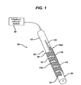
- FIGS. 1-3 illustrate one embodiment of a surgical device 10 that is configured to facilitate movement of a surgical instrument relative to tissue.
- the device 10 includes an endoscope 12 (only a portion of which is shown) and a tissue engaging section 14 that is appended a distal portion 12a of the endoscope 12.
- At least a portion of the tissue engaging section 14 includes a porous fabric 16 that covers at least a tissue contacting surface 18 of the tissue engaging section 14.
- the tissue engaging section 14 can include at its proximal end 14a a conduit 34 that is in communication with a vacuum source 20, and optionally an irrigation source, that can be part of or separate from the endoscope system.
- the invention is applicable to virtually any surgical tool.
- the surgical tool used with the invention is an endoscope
- it can be any flexible, elongate member that is capable of being inserted into the body, such as through a natural orifice.
- FIG. 1 shows an insertion portion 22 of an endoscope 12 that is to be inserted into a patient's body, such as through a natural orifice.
- At least a portion of the endoscope is flexible and the endoscope may have a stearable portion 24 at a distal end thereof.
- the tissue engaging section 14 can take the form of virtually any member that can be appended to an outer surface 26 of the endoscope 12. Generally, the tissue engaging section 14 is secured to the endoscope 12 in such a manner that it does not move independent of the endoscope. The tissue engaging section 14 thus can take a variety of forms that enable it to securely fit over the endoscope 12.
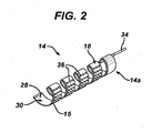
- the tissue engaging section 14 is in the form of a helical, ribbon-like member 15 having an outer tissue-contacting surface 18 and an inner tool-contacting surface 28.
- the helices of the helical member 15 define a central lumen 30 within which the endoscope can seat and be engaged by the tool-contacting surface 28.
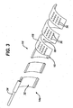
- the outer and inner surfaces 18, 28 of the helical member define a hollow chamber 32 ( FIG.
- conduit 34 that extends proximally from the helical member 15.
- a plurality of holes 36 is formed in the tissue contacting surface 18 in fluid communication with the hollow chamber 32 and thus conduit 34 and vacuum source 20, and optionally an irrigation source. Fluid can be passed through conduit 34 and out of holes 36, or a vacuum force can be drawn through the holes 36, as will be explained below.
- the helical member 15 can be applied to the endoscope by a variety of techniques that will enable it to remain secured to the endoscope and unable to move independent of the endoscope.
- the helical member 15 is appended to the endoscope by an interference fit. This can be effected by forming the helical member 15 from a material that is at least somewhat elastic (e.g., a superelastic alloy or a shape memory material).
- the inner diameter of the lumen 30 when the helical member 15 is in a relaxed condition can be slightly less than the outer diameter of the endoscope 12.
- a force can be applied to the helical member 15, such as by axially compressing the helical member 15, to increase the inner diameter of the lumen 30.
- the helical member 15 can then be placed over the endoscope 12 in an appropriate location and the force is removed, allowing the inner diameter of the helical member 15 to decrease and engage the endoscope in an interference fit,
- the tissue engaging section 14 can be applied to the endoscope 12 at various appropriate locations. Generally, however, the tissue engaging section 14 is applied at a distal portion of the endoscope 12. In one example, as shown in FIG. 1 , the tissue engaging section 14 is applied proximal to the distal most end. In one embodiment the tissue engaging section 14 is applied just a proximal to stearable portion 24.
- a porous fabric 16 extends over at least a portion of the tissue contacting surface 18 of the tissue engaging section 14.
- the material from which the porous fabric 16 can be made of virtually any material that is biocompatible, having properties that enable an outer surface of the fabric to contact tissue in such a way that there is significant friction between the contact tissue and the fabric and any device over which the fabric is applied.
- the fabric material is a porous material such as a mesh material, which can be woven or non-woven.
- the material from which the mesh is formed can include a variety of synthetic and non-synthetic materials. Examples of synthetic materials include polymers, such as polypropylene, polyethylene, polyester, polytetrafluoroethylene, and nylon. Examples of non-synthetic mesh materials include, but are not limited to silk, cotton, and stainless steel.
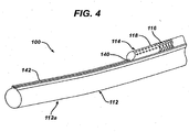
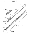
- FIGS. 4-5 illustrate another disclosure of a surgical device 100, not of the present invention, that is configured to facilitate movement of a surgical instrument relative to tissue.
- the device 100 includes an endoscope 112 (only a portion of which is shown) and a tissue engaging section 114 that is appended to a distal portion 112a of the endoscope.
- the tissue engaging section 114 is of a type that is moveable with respect to the endoscope 112.
- At least a portion of the tissue engaging section 114 includes a porous fabric 116 that covers at least a tissue contacting surface 118 of the tissue engaging section 114.
- the tissue engaging section 114 includes a mating element 140 that mates with a corresponding mating receptacle 142 on the endoscope to enable the tissue engaging section 114 to engage the endoscope 112 and to move relative to the endoscope.
- the tissue engaging section 114 may include a proximal end (not shown) or a conduit (not shown) extending from the proximal end that is in fluid communication with an irrigation and/or vacuum source (not shown) that can be part of or separate from the endoscope system.
- the endoscope 112 can be of the type described above with respect to FIGS. 1-3 . However, as shown in FIGS. 4-5 , the endoscope 112 includes a mating receptacle 142 that is configured to mate with a corresponding mating element 140 on the tissue engaging section 114 to enable the tissue engaging section 114 to be appended to the endoscope 112 in such a way that the tissue engaging section and the endoscope are able to move independent of one another. Although illustrated as a female mating receptacle, one skilled in the art will understand that the mating receptacle 142 of the endoscope 112 can alternatively be a male-type member.
- mating element of the tissue engaging section is illustrated as a male element it can alternatively be a female element.
- mating receptacle 142 is in the form of a C-shaped channel or track that is configured to receive a complimentary mating element 140 of the tissue engaging section 114, such as a T-shaped member.
- the tissue engaging section 114 can be in the form of an accessory member 154 that is appended to the endoscope 112, such as an accessory channel of an endoscope, in a manner such that it is able to move relative to the endoscope.
- the accessory member 154 can take a variety of forms. However, like the endoscope, the accessory member 154 can be a thin, elongate and flexible member that is capable of being inserted into a natural orifice of a patient. In one embodiment, as shown in FIGS. 4-5 the accessory member 154 can be a flexible, elongate tubular member having mating element 140 appended to a bottom portion thereof.
- An outer wall 156 of the accessory member 154 defines a lumen (not shown) that extends within the accessory member 154 and is in fluid communication with an irrigation/vacuum source (not shown) directly or through another conduit (not shown).
- a distal end 154a of the accessory member 154 can include a plurality of holes 158 in fluid communication with the lumen (not shown) disposed within the accessory member.
- the distal end 157 of the accessory member 154 is closed.
- the holes 158 are constructed such that fluid can be passed through the accessory member 154 and out of holes 158 or a vacuum force can be drawn through the holes 158 as will be explained below.
- a fabric 116 can cover a tissue contacting outer surface 156 of the accessory member 154.
- the 116 fabric can be a mesh material of the type described above with respect to FIGS. 1-3 .
- the devices described herein are applicable to a variety of surgical procedures in which a surgical device must be advanced through the body of a patient along a relatively long and potentially tortuous pathway. Exemplary techniques for using the devices described herein will be described in the context of an endoscopic procedure in which an endoscope traverses a portion of the colon.
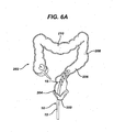
- FIGS. 6A and 6B illustrate the use of a surgical device 10 of the type shown in FIGS. 1-3 in a procedure in which the endoscope 12 enters a patient through the anus 200 and is passed into the colon 202.
- the endoscope 12 is passed through the rectum 204 which, normally after slightly more than 90° right hand turn, leads to the sigmoid colon 206.
- the surgical device 10 of the invention can assist in this passage. That is, as a turn in the passageway is encountered, tissue tends to bunch up against the distal end of the endoscope, making further distal advancement of the endoscope difficult, particularly when it is necessary to make a turn.
- the device 10 can assist in what is referred to as the "push-pull" technique, in which a surgeon attempts to hook the colon and then pulls the endoscope back in an attempt to straighten the lumen of the colon.
- the suction applied by the device 10 aids the surgeon in grasping and maintaining control of the colon rendering the push-pull technique more reliable.
- an irrigation fluid can be passed through holes 36 after the vacuum is withdrawn and during or after advancement of the endoscope 12 to reduce friction between the fabric that covers the helical member and the tissue.
- the process of applying vacuum force, removing or reducing the vacuum, applying irrigation to reduce friction, and advancing the endoscope can be repeated as necessary as the endoscope is advanced from the descending colon 208 to the transverse colon 210.
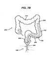
- FIGS. 7A and 7B illustrate the use of a surgical device 100 in a similar surgical procedure that requires passage of an endoscope 112 through the colon 202.
- the endoscope 112 enters the patient through the anus 200 and passes through the rectum 204 into the sigmoid colon 206 as shown in FIG. 7A .
- the passageway within the colon becomes tortuous as the colon makes a sharp (greater than 90°) left turn into the descending colon 208.
- suction can be applied to the device 100 by drawing a vacuum through accessory member 154, thus anchoring the endoscope to the passageway to some extent.
- the endoscope 112 can be advanced distally beyond the accessory member 154 as shown in FIG. 7B .
- an irrigation fluid can be passed through holes 158 in the accessory member 154 after the vacuum is withdrawn and during or after advancement of the endoscope 112.
- the accessory member can be advanced distally so that it is approximately adjacent the distal end of the endoscope (such as shown in FIG. 7A ). This procedure can be repeated as necessary to advance the endoscope.
- the devices disclosed herein can be designed to be disposed of after a single use, or they can be designed to be used multiple times. In either case, however, the device can be reconditioned for reuse after at least one use. Reconditioning can include any combination of the steps of disassembly of the device, followed by cleaning or replacement of particular pieces, and subsequent reassembly. In particular, the device can be disassembled, and any number of the particular pieces or parts of the device can be selectively replaced or removed in any combination. Upon cleaning and/or replacement of particular parts, the device can be reassembled for subsequent use either at a reconditioning facility, or by a surgical team immediately prior to a surgical procedure.
- reconditioning of a device can utilize a variety of techniques for disassembly, cleaning/replacement, and reassembly. Use of such techniques, and the resulting reconditioned device, are all within the scope of the present application.
- the invention described herein will be processed before surgery.
- a new or used instrument is obtained and if necessary cleaned.
- the instrument can then be sterilized.
- the instrument is placed in a closed and sealed container, such as a plastic or TYVEK bag,
- the container and instrument are then placed in a field of radiation that can penetrate the container, such as gamma radiation, x-rays, or high-energy electrons.
- the radiation kills bacteria on the instrument and in the container.
- the sterilized instrument can then be stored in the sterile container.
- the sealed container keeps the instrument sterile until it is opened in the medical facility.
- device is sterilized. This can be done by any number of ways known to those skilled in the art including beta or gamma radiation, ethylene oxide, steam.
Description
- The present invention relates to surgical devices useful for moving tissue and/or effecting movement of device relative to tissue, and particularly through hollow organs in a patient.
- Many surgical procedures require the movement or dissection of tissue, or the movement of a device relative to tissue. Space constraints as well as the relative remoteness of a distal end of a surgical tool from the surgeon can make it difficult to move tissue, particularly in endoscopic procedures that require surgical instruments to traverse a tortuous pathway though a tubular organ such as the colon. In some surgical procedures, particularly in laparoscopic and endoscopic procedures, movement of the surgical device can be challenging because it is located in a relatively constrained space that is remote from the surgeon. For example, it can be difficult for an endoscope to follow certain curves within the colon. Accordingly, there is a need for devices that conveniently and effectively enable the movement of tissue and/or the movement of surgical tools relative to tissue.
-
WO 01/54565 A2 -
WO 03/039354 A1 -
US4834724 describes a device for aspirating fluids from a body cavity or hollow organ, specifically a nasogastric tube with a portion to be positioned in the stomach that is formed in an elongated helix and has one or more aspirating ports facing inwardly of the helical portion for spacing such ports from the gastric mucosa. -
US4681564 describes a catheter assembly with a balloon element shaped in a helical configuration. The balloon element has openings for passing fluids into a body space. - The present invention provides devices to facilitate the movement of surgical devices through tortuous passageways (e.g., the colon) in the body. In one aspect, there is an endoscopic device as defined in claim 1. In one embodiment the insertion section is a surgical tool for placement within the body, such as an endoscope.
- In another disclosure the tissue engaging section is an accessory channel that is appended to an endoscope such that it can move independent of the endoscope. In another embodiment the tissue engaging section is a member that is appended to an endoscope, such as in an interference fit, that it is not movable relative to the endoscope.
- Methods of moving a surgical device through a passageway in the body are provided but are not claimed. For example, a method of advancing a surgical instrument through a body lumen can include providing an elongate surgical instrument having an insertion portion that has appended thereto a tissue engaging section having an outer wall with a plurality of openings formed therein. The method further includes inserting the insertion portion into a hollow body lumen having a tortuous path; communicating a vacuum force to the tissue engaging section such that tissue of the body lumen is drawn against the tissue engaging section; releasing the vacuum force and moving the insertion portion within the body lumen; and repeating the steps of communicating the vacuum force, releasing the vacuum force and moving the elongate insertion portion to navigate the elongate insertion portion through the body lumen.
- The invention will be more fully understood from the following detailed description taken in conjunction with the accompanying drawings, in which:
-
FIG. 1 is a perspective view of a portion of an endoscopic device according to one embodiment of the invention having a stationary tissue engaging section appended thereto and porous fabric covering part of the tissue engaging section; -
FIG. 2 is a perspective view of a tissue engaging section useful with the endoscopic device of the type shown inFIG. 1 ; -
FIG. 3 is a partial sectional view of a portion of a tissue engaging section of the type shown inFIG. 2 ; -
FIG. 4 is a perspective view of a portion of an endoscopic device not of the invention having a movable tissue engaging section appended thereto and porous fabric covering part of the tissue engaging section; -
FIG. 4A is a perspective view of the endoscopic device ofFIG. 4 with the tissue engaging section in a more distal position; -
FIG. 5 is an exploded view of the endoscopic device ofFIG. 4 ; -
FIG. 6A schematically illustrates an endoscopic device of the type shown inFIG. 1 in a first position in use during an endoscopic procedure; -
FIG. 6B schematically illustrates an endoscopic device of the type shown inFIG. 1 in a second position in use during an endoscopic procedure; -
FIG. 7A schematically illustrates an endoscopic device of the type shown inFIG. 4 in a first position in use during an endoscopic procedure; and -
FIG. 7B schematically illustrates an endoscopic device of the type shown inFIG. 4 in a second position in use during an endoscopic procedure. - Certain exemplary embodiments will now be described to provide an overall understanding of the principles of the structure, function, manufacture, and use of the devices disclosed herein. One or more examples of these embodiments are illustrated in the accompanying drawings. Those skilled in the art will understand that the devices specifically described herein and illustrated in the accompanying drawings are non-limiting exemplary embodiments and that the scope of the present invention is defined solely by the claims. The features illustrated or described in connection with one exemplary embodiment may be combined with the features of other embodiments. Such modifications and variations are intended to be included within the scope of the present invention.
- The present invention generally provides devices for moving tissue and/or moving the devices relative to the tissue during a surgical procedure. While the devices disclosed herein can be used in conventional, open surgical procedures, they are particularly useful in minimally invasive surgical procedures, particularly endoscopic procedures. The principles described herein can be applicable to the particular types of tools described herein, and to a variety of other surgical tools having similar functions. In addition, the tools can be used alone in a surgical procedure, or they can be used in conjunction with other devices that facilitate minimally invasive surgical procedures. A particularly useful aspect of the systems and devices disclosed herein is that they enable movement and manipulation of a surgical instrument through a pathway in the body. That is, the invention enables passage of a device through a pathway in the body such that it is able to move relative to the body tissue and pass through regions of the body that can be difficult to traverse, such as tortuous organs like the colon.
- The invention is described herein with reference to an endoscope that is to be moved through an organ in the body. However, a person skilled in the art will understand that the invention is applicable to a variety of other surgical tools that must be passed through passageway in the body, such as hollow organs, during a surgical procedure and particularly during minimally invasive surgical procedures such as endoscopic procedures.
- A person skilled in the art will appreciate that the present invention has application in conventional endoscopic and open surgical instrumentation as well application in robotic-assisted surgery.
-
FIGS. 1-3 illustrate one embodiment of asurgical device 10 that is configured to facilitate movement of a surgical instrument relative to tissue. As shown, thedevice 10 includes an endoscope 12 (only a portion of which is shown) and atissue engaging section 14 that is appended adistal portion 12a of theendoscope 12. At least a portion of thetissue engaging section 14 includes aporous fabric 16 that covers at least atissue contacting surface 18 of thetissue engaging section 14. Thetissue engaging section 14 can include at itsproximal end 14a aconduit 34 that is in communication with avacuum source 20, and optionally an irrigation source, that can be part of or separate from the endoscope system. - As noted above, the invention is applicable to virtually any surgical tool. In the event that the surgical tool used with the invention is an endoscope is used, it can be any flexible, elongate member that is capable of being inserted into the body, such as through a natural orifice. For example,
FIG. 1 shows aninsertion portion 22 of anendoscope 12 that is to be inserted into a patient's body, such as through a natural orifice. At least a portion of the endoscope is flexible and the endoscope may have astearable portion 24 at a distal end thereof. - The
tissue engaging section 14 can take the form of virtually any member that can be appended to anouter surface 26 of theendoscope 12. Generally, thetissue engaging section 14 is secured to theendoscope 12 in such a manner that it does not move independent of the endoscope. Thetissue engaging section 14 thus can take a variety of forms that enable it to securely fit over theendoscope 12. In the present invention, thetissue engaging section 14 is in the form of a helical, ribbon-like member 15 having an outer tissue-contactingsurface 18 and an inner tool-contactingsurface 28. The helices of thehelical member 15 define acentral lumen 30 within which the endoscope can seat and be engaged by the tool-contactingsurface 28. The outer andinner surfaces FIG. 3 ) that is in fluid communication with avacuum source 20, and optionally an irrigation source, throughconduit 34 that extends proximally from thehelical member 15. A plurality ofholes 36 is formed in thetissue contacting surface 18 in fluid communication with thehollow chamber 32 and thusconduit 34 andvacuum source 20, and optionally an irrigation source. Fluid can be passed throughconduit 34 and out ofholes 36, or a vacuum force can be drawn through theholes 36, as will be explained below. - The
helical member 15 can be applied to the endoscope by a variety of techniques that will enable it to remain secured to the endoscope and unable to move independent of the endoscope. In one example, thehelical member 15 is appended to the endoscope by an interference fit. This can be effected by forming thehelical member 15 from a material that is at least somewhat elastic (e.g., a superelastic alloy or a shape memory material). Moreover, the inner diameter of thelumen 30 when thehelical member 15 is in a relaxed condition can be slightly less than the outer diameter of theendoscope 12. A force can be applied to thehelical member 15, such as by axially compressing thehelical member 15, to increase the inner diameter of thelumen 30. Thehelical member 15 can then be placed over theendoscope 12 in an appropriate location and the force is removed, allowing the inner diameter of thehelical member 15 to decrease and engage the endoscope in an interference fit, - The
tissue engaging section 14 can be applied to theendoscope 12 at various appropriate locations. Generally, however, thetissue engaging section 14 is applied at a distal portion of theendoscope 12. In one example, as shown inFIG. 1 , thetissue engaging section 14 is applied proximal to the distal most end. In one embodiment thetissue engaging section 14 is applied just a proximal tostearable portion 24. - As noted above, a
porous fabric 16 extends over at least a portion of thetissue contacting surface 18 of thetissue engaging section 14. The material from which theporous fabric 16 can be made of virtually any material that is biocompatible, having properties that enable an outer surface of the fabric to contact tissue in such a way that there is significant friction between the contact tissue and the fabric and any device over which the fabric is applied. In one embodiment, the fabric material is a porous material such as a mesh material, which can be woven or non-woven. The material from which the mesh is formed can include a variety of synthetic and non-synthetic materials. Examples of synthetic materials include polymers, such as polypropylene, polyethylene, polyester, polytetrafluoroethylene, and nylon. Examples of non-synthetic mesh materials include, but are not limited to silk, cotton, and stainless steel. -
FIGS. 4-5 illustrate another disclosure of asurgical device 100, not of the present invention, that is configured to facilitate movement of a surgical instrument relative to tissue. As shown, thedevice 100 includes an endoscope 112 (only a portion of which is shown) and atissue engaging section 114 that is appended to adistal portion 112a of the endoscope. As explained below, thetissue engaging section 114 is of a type that is moveable with respect to theendoscope 112. At least a portion of thetissue engaging section 114 includes aporous fabric 116 that covers at least atissue contacting surface 118 of thetissue engaging section 114. Thetissue engaging section 114 includes amating element 140 that mates with acorresponding mating receptacle 142 on the endoscope to enable thetissue engaging section 114 to engage theendoscope 112 and to move relative to the endoscope. Thetissue engaging section 114 may include a proximal end (not shown) or a conduit (not shown) extending from the proximal end that is in fluid communication with an irrigation and/or vacuum source (not shown) that can be part of or separate from the endoscope system. - The
endoscope 112 can be of the type described above with respect toFIGS. 1-3 . However, as shown inFIGS. 4-5 , theendoscope 112 includes amating receptacle 142 that is configured to mate with acorresponding mating element 140 on thetissue engaging section 114 to enable thetissue engaging section 114 to be appended to theendoscope 112 in such a way that the tissue engaging section and the endoscope are able to move independent of one another. Although illustrated as a female mating receptacle, one skilled in the art will understand that themating receptacle 142 of theendoscope 112 can alternatively be a male-type member. Similarly, while the mating element of the tissue engaging section is illustrated as a male element it can alternatively be a female element. In the illustrated embodiment,mating receptacle 142 is in the form of a C-shaped channel or track that is configured to receive acomplimentary mating element 140 of thetissue engaging section 114, such as a T-shaped member. - The
tissue engaging section 114 can be in the form of anaccessory member 154 that is appended to theendoscope 112, such as an accessory channel of an endoscope, in a manner such that it is able to move relative to the endoscope. Theaccessory member 154 can take a variety of forms. However, like the endoscope, theaccessory member 154 can be a thin, elongate and flexible member that is capable of being inserted into a natural orifice of a patient. In one embodiment, as shown inFIGS. 4-5 theaccessory member 154 can be a flexible, elongate tubular member havingmating element 140 appended to a bottom portion thereof. Anouter wall 156 of theaccessory member 154 defines a lumen (not shown) that extends within theaccessory member 154 and is in fluid communication with an irrigation/vacuum source (not shown) directly or through another conduit (not shown). - A
distal end 154a of theaccessory member 154 can include a plurality ofholes 158 in fluid communication with the lumen (not shown) disposed within the accessory member. In one embodiment, thedistal end 157 of theaccessory member 154 is closed. Theholes 158 are constructed such that fluid can be passed through theaccessory member 154 and out ofholes 158 or a vacuum force can be drawn through theholes 158 as will be explained below. - As described above with respect to
FIGS. 1-3 , afabric 116 can cover a tissue contactingouter surface 156 of theaccessory member 154. The 116 fabric can be a mesh material of the type described above with respect toFIGS. 1-3 . - One skilled in the art will appreciate that the devices described herein are applicable to a variety of surgical procedures in which a surgical device must be advanced through the body of a patient along a relatively long and potentially tortuous pathway. Exemplary techniques for using the devices described herein will be described in the context of an endoscopic procedure in which an endoscope traverses a portion of the colon.
-
FIGS. 6A and6B illustrate the use of asurgical device 10 of the type shown inFIGS. 1-3 in a procedure in which theendoscope 12 enters a patient through theanus 200 and is passed into thecolon 202. As shown inFIG. 6A , theendoscope 12 is passed through therectum 204 which, normally after slightly more than 90° right hand turn, leads to thesigmoid colon 206. Because it can be difficult to maneuver an endoscope through the tortuous pathway leading to thesigmoid colon 206, for example, thesurgical device 10 of the invention can assist in this passage. That is, as a turn in the passageway is encountered, tissue tends to bunch up against the distal end of the endoscope, making further distal advancement of the endoscope difficult, particularly when it is necessary to make a turn. - Thus, as shown in
FIG 6A , during passage of an endoscope through the colon, the endoscope encounters a portion of the passageway, e.g., leading to thesigmoid colon 206, that requires a difficult maneuver such as a sharp turn. At this point, using thedevice 10, suction can be applied to the device, drawing a vacuum throughholes 36 in helical member 15 (FIGS. 1-3 ). The results in tissue being drawn to thehelical member 15. Thus, as shown inFIG. 6A , as suction is applied, the drawing of tissue against thehelical member 15 causes the normal passageway of the colon in the vicinity of thesigmoid colon 206 to become straighter than normal. (Compare the straightened passageway shown inFIG. 6A in the vicinity of thesigmoid colon 206 to the normal anatomy of the same region shown inFIG. 6B .) Thedevice 10 can assist in what is referred to as the "push-pull" technique, in which a surgeon attempts to hook the colon and then pulls the endoscope back in an attempt to straighten the lumen of the colon. The suction applied by thedevice 10 aids the surgeon in grasping and maintaining control of the colon rendering the push-pull technique more reliable. Once the passageway is straightened as a result of applying the vacuum force and pulling the endoscope back to straighten the colon, the vacuum can be withdrawn or reduced and, as shown inFIG. 6B , theendoscope 12 is further advanced. Optionally, an irrigation fluid can be passed throughholes 36 after the vacuum is withdrawn and during or after advancement of theendoscope 12 to reduce friction between the fabric that covers the helical member and the tissue. The process of applying vacuum force, removing or reducing the vacuum, applying irrigation to reduce friction, and advancing the endoscope can be repeated as necessary as the endoscope is advanced from the descendingcolon 208 to thetransverse colon 210. -
FIGS. 7A and7B illustrate the use of asurgical device 100 in a similar surgical procedure that requires passage of anendoscope 112 through thecolon 202. Similar to the procedure described above, theendoscope 112 enters the patient through theanus 200 and passes through therectum 204 into thesigmoid colon 206 as shown inFIG. 7A . At the junction of thesigmoid colon 206 and the descendingcolon 208, the passageway within the colon becomes tortuous as the colon makes a sharp (greater than 90°) left turn into the descendingcolon 208. At a juncture such as this, where endoscope advancement becomes difficult as tissue bunches up against the distal end of the endoscope, suction can be applied to thedevice 100 by drawing a vacuum throughaccessory member 154, thus anchoring the endoscope to the passageway to some extent. At this point, theendoscope 112 can be advanced distally beyond theaccessory member 154 as shown inFIG. 7B . Optionally, an irrigation fluid can be passed throughholes 158 in theaccessory member 154 after the vacuum is withdrawn and during or after advancement of theendoscope 112. Once theendoscope 112 is advanced beyond theaccessory member 154, the accessory member can be advanced distally so that it is approximately adjacent the distal end of the endoscope (such as shown inFIG. 7A ). This procedure can be repeated as necessary to advance the endoscope. - The devices disclosed herein can be designed to be disposed of after a single use, or they can be designed to be used multiple times. In either case, however, the device can be reconditioned for reuse after at least one use. Reconditioning can include any combination of the steps of disassembly of the device, followed by cleaning or replacement of particular pieces, and subsequent reassembly. In particular, the device can be disassembled, and any number of the particular pieces or parts of the device can be selectively replaced or removed in any combination. Upon cleaning and/or replacement of particular parts, the device can be reassembled for subsequent use either at a reconditioning facility, or by a surgical team immediately prior to a surgical procedure. Those skilled in the art will appreciate that reconditioning of a device can utilize a variety of techniques for disassembly, cleaning/replacement, and reassembly. Use of such techniques, and the resulting reconditioned device, are all within the scope of the present application.
- Preferably, the invention described herein will be processed before surgery. First, a new or used instrument is obtained and if necessary cleaned. The instrument can then be sterilized. In one sterilization technique, the instrument is placed in a closed and sealed container, such as a plastic or TYVEK bag, The container and instrument are then placed in a field of radiation that can penetrate the container, such as gamma radiation, x-rays, or high-energy electrons. The radiation kills bacteria on the instrument and in the container. The sterilized instrument can then be stored in the sterile container. The sealed container keeps the instrument sterile until it is opened in the medical facility.
- It is preferred that device is sterilized. This can be done by any number of ways known to those skilled in the art including beta or gamma radiation, ethylene oxide, steam.
- One skilled in the art will appreciate further features and advantages of the invention based on the above-described embodiments. Accordingly, the invention is not to be limited by what has been particularly shown and described, except as indicated by the appended claims.
Claims (7)
- An endoscopic device (10), comprising:an elongate insertion element (22) adapted to be placed within a patient's body;a tissue engaging section (14) appended to at least a portion of the insertion element, the tissue engaging section having an outer tissue contacting surface (18) and an inner tool-contacting surface (28), wherein a plurality of openings (36) are formed in the outer tissue contacting surface (18) that communicate with a hollow chamber (32), the hollow chamber (32) defined by the outer surface (18) and the inner surface (28),wherein the hollow chamber is configured to communicate with a vacuum source, and a porous fabric (16) extends over at least a portion of the tissue engaging section; and
the device is characterised in that the tissue engaging section is in the form of an elongate helical ribbon (15). - The device of claim 1, wherein the porous fabric is a mesh material.
- The device of claim 1, wherein the helical ribbon includes a conduit (34) extending from a proximal end thereof, the conduit communicating with the hollow chamber and the vacuum source.
- The device of claim 1, wherein the inner surface (28) defines an inner diameter (30), the inner surface being configured to surround and contact at least a portion of a distal end of the elongate insertion element in an interference fit.
- The device of claim 4, wherein the inner diameter of the helical ribbon is selectively variable between a relaxed state in which the inner diameter is less than an outer diameter of the elongate insertion element and a stressed condition in which the inner diameter is greater than an outer diameter of the elongate insertion element.
- The device of claim 5, wherein the helical ribbon is made of a superelastic alloy or a shape memory material.
- The device of claim 1, wherein the elongate insertion element is an endoscope.
Applications Claiming Priority (1)
| Application Number | Priority Date | Filing Date | Title |
|---|---|---|---|
| US11/778,142 US8157727B2 (en) | 2007-07-16 | 2007-07-16 | Surgical methods and devices with movement assistance |
Publications (2)
| Publication Number | Publication Date |
|---|---|
| EP2016887A1 EP2016887A1 (en) | 2009-01-21 |
| EP2016887B1 true EP2016887B1 (en) | 2016-08-24 |
Family
ID=39831966
Family Applications (1)
| Application Number | Title | Priority Date | Filing Date |
|---|---|---|---|
| EP08252415.8A Active EP2016887B1 (en) | 2007-07-16 | 2008-07-16 | Endoscopic devices with movement assistance |
Country Status (6)
| Country | Link |
|---|---|
| US (1) | US8157727B2 (en) |
| EP (1) | EP2016887B1 (en) |
| JP (1) | JP5280123B2 (en) |
| CN (1) | CN101347323B (en) |
| AU (1) | AU2008203052B2 (en) |
| CA (1) | CA2637525C (en) |
Families Citing this family (16)
| Publication number | Priority date | Publication date | Assignee | Title |
|---|---|---|---|---|
| US8100930B2 (en) * | 2007-03-30 | 2012-01-24 | Ethicon Endo-Surgery, Inc. | Tissue moving surgical device |
| US8142356B2 (en) * | 2007-03-30 | 2012-03-27 | Ethicon Endo-Surgery, Inc. | Method of manipulating tissue |
| US8157727B2 (en) * | 2007-07-16 | 2012-04-17 | Ethicon Endo-Surgery, Inc. | Surgical methods and devices with movement assistance |
| US8540744B2 (en) * | 2008-04-01 | 2013-09-24 | Ethicon Endo-Surgery, Inc. | Tissue penetrating surgical device |
| JP5559785B2 (en) | 2008-07-18 | 2014-07-23 | ボストン サイエンティフィック サイムド,インコーポレイテッド | Guided endoscope |
| WO2012047939A2 (en) * | 2010-10-04 | 2012-04-12 | Ind Platforms Llc | Expandable devices, rail systems, and motorized devices |
| US9402531B2 (en) * | 2012-07-05 | 2016-08-02 | Pavilion Medical Innovations, Llc | Endoscopic cannulas and methods of using the same |
| US10348941B2 (en) | 2014-07-30 | 2019-07-09 | Karl Storz Endovision, Inc. | Durable flexible circuit assembly |
| CN104644260B (en) * | 2014-09-12 | 2018-03-09 | 密雷 | A kind of minimally invasive guarantor's courage operation polyp substrate flood pattern |
| US20160271371A1 (en) * | 2015-03-20 | 2016-09-22 | Cardica, Inc. | Guidewire system and method for advancement through a torturous path |
| CN105411519B (en) * | 2015-12-21 | 2017-11-14 | 张为 | A kind of movable foramen intervertebrale lens system |
| KR20180109947A (en) * | 2016-02-11 | 2018-10-08 | 사우디 아라비안 오일 컴퍼니 | Attaching a toolless spring to the C-channel and using it |
| EP3422924A4 (en) * | 2016-02-29 | 2019-12-04 | Morena Medical Applications Ltd. | Endoscope with shared working channel |
| CN110191667B (en) | 2016-08-18 | 2022-06-03 | 海王星医疗公司 | Device and method for enhancing the visual effects of the small intestine |
| CN109512476B (en) * | 2018-12-19 | 2020-08-28 | 四川大学华西医院 | Intraoperative traction device for early cancers of digestive tract |
| WO2023225520A2 (en) * | 2022-05-16 | 2023-11-23 | Neptune Medical Inc. | External working channels for endoscopic devices |
Citations (2)
| Publication number | Priority date | Publication date | Assignee | Title |
|---|---|---|---|---|
| US4681564A (en) * | 1985-10-21 | 1987-07-21 | Landreneau Michael D | Catheter assembly having balloon extended flow path |
| US4834724A (en) * | 1987-04-06 | 1989-05-30 | Geiss Alan C | Device for aspirating fluids from a body cavity or hollow organ |
Family Cites Families (63)
| Publication number | Priority date | Publication date | Assignee | Title |
|---|---|---|---|---|
| US55869A (en) * | 1866-06-26 | Samuel huffman | ||
| US69719A (en) * | 1867-10-08 | Improvement in mechanical movement | ||
| US52593A (en) * | 1866-02-13 | Foot-warmer | ||
| US6691A (en) * | 1849-09-04 | Machine fob weaving harness for looms | ||
| US982232A (en) | 1908-01-13 | 1911-01-24 | John A Bartholomew | Medicinal applicator and swab. |
| US2767705A (en) * | 1954-10-08 | 1956-10-23 | Technical Oil Tool Corp | Sigmoidoscope with suction attachment for immobilizing adjacent tissue |
| US3589356A (en) | 1969-09-04 | 1971-06-29 | Daniel Silverman | Method for everting and extraverting flexible tubing into a body cavity |
| US3823720A (en) * | 1972-06-21 | 1974-07-16 | D Tribble | Surgical drain |
| US4158916A (en) * | 1977-07-20 | 1979-06-26 | Adler Harold A | Suction apparatus |
| US4794912A (en) | 1987-08-17 | 1989-01-03 | Welch Allyn, Inc. | Borescope or endoscope with fluid dynamic muscle |
| DE3943872B4 (en) | 1989-08-01 | 2005-08-25 | Stm Medizintechnik Starnberg Gmbh | Device for introducing a medical endoscope into a body canal |
| US5127909A (en) | 1990-04-05 | 1992-07-07 | United States Surgical Corporation | Flapper valve for an insufflation cannula assembly |
| US5658307A (en) | 1990-11-07 | 1997-08-19 | Exconde; Primo D. | Method of using a surgical dissector instrument |
| AU2185192A (en) | 1991-05-29 | 1993-01-08 | Origin Medsystems, Inc. | Retraction apparatus and methods for endoscopic surgery |
| US5235966A (en) | 1991-10-17 | 1993-08-17 | Jay Jamner | Endoscopic retractor |
| US5355897A (en) | 1992-04-16 | 1994-10-18 | Ethicon, Inc. | Method of performing a pyloroplasty/pylorectomy using a stapler having a shield |
| DE4244990C2 (en) | 1992-12-15 | 2002-03-14 | Stm Medtech Starnberg | Device for moving an endoscope shaft along a channel-like cavity |
| US5522795A (en) | 1993-01-25 | 1996-06-04 | United States Surgical Corporation | Endoscopic swab device |
| US5624381A (en) | 1994-08-09 | 1997-04-29 | Kieturakis; Maciej J. | Surgical instrument and method for retraction of an anatomic structure defining an interior lumen |
| US5989230A (en) * | 1996-01-11 | 1999-11-23 | Essex Technology, Inc. | Rotate to advance catheterization system |
| US5885209A (en) | 1996-02-02 | 1999-03-23 | Green; Anthony D. | Endoscopic working channel and method of making same |
| EP0807415B1 (en) | 1996-05-09 | 2003-12-03 | Olympus Optical Co., Ltd. | A cavity retaining tool for bone surgery, a cavity retaining tool for general surgery, an endoscopic surgery system involving the use of a cavity retaining tool |
| IT1285533B1 (en) * | 1996-10-22 | 1998-06-08 | Scuola Superiore Di Studi Universitari E Di Perfezionamento Sant Anna | ENDOSCOPIC ROBOT |
| US6007521A (en) | 1997-01-07 | 1999-12-28 | Bidwell; Robert E. | Drainage catheter system |
| US5836913A (en) | 1997-05-02 | 1998-11-17 | Innerdyne, Inc. | Device and method for accessing a body cavity |
| US6338712B2 (en) * | 1997-09-17 | 2002-01-15 | Origin Medsystems, Inc. | Device to permit offpump beating heart coronary bypass surgery |
| US5931845A (en) | 1998-02-20 | 1999-08-03 | Amyette; Carol R. | Pierced body part cleaning device |
| US6030365A (en) | 1998-06-10 | 2000-02-29 | Laufer; Michael D. | Minimally invasive sterile surgical access device and method |
| US20040097996A1 (en) | 1999-10-05 | 2004-05-20 | Omnisonics Medical Technologies, Inc. | Apparatus and method of removing occlusions using an ultrasonic medical device operating in a transverse mode |
| US6699179B2 (en) * | 2000-01-27 | 2004-03-02 | Scimed Life Systems, Inc. | Catheter introducer system for exploration of body cavities |
| US6517477B1 (en) | 2000-01-27 | 2003-02-11 | Scimed Life Systems, Inc. | Catheter introducer system for exploration of body cavities |
| JP4939717B2 (en) | 2000-05-02 | 2012-05-30 | ウィルソン−クック メディカル インコーポレイテッド | Catheter with reversible sleeve O.D. T.A. Introducing device for L |
| US6309346B1 (en) * | 2000-06-29 | 2001-10-30 | Ashkan Farhadi | Creeping colonoscope |
| IL138237A (en) | 2000-09-04 | 2008-12-29 | Stryker Gi Ltd | Double sleeve endoscope |
| JP4180367B2 (en) * | 2000-10-16 | 2008-11-12 | フィッシャー アンド ペイケル ヘルスケア リミテッド | Equipment used for humidifying gases in medical procedures |
| JP2002125921A (en) * | 2000-10-20 | 2002-05-08 | Norikazu Hattori | Attachment of endoscope and endoscope |
| US6786898B2 (en) * | 2003-01-15 | 2004-09-07 | Medtronic, Inc. | Methods and tools for accessing an anatomic space |
| US6676597B2 (en) * | 2001-01-13 | 2004-01-13 | Medtronic, Inc. | Method and device for organ positioning |
| DE60122783T2 (en) * | 2001-02-28 | 2007-09-13 | Kist (Korean Institute Of Science And Technology) | ENDOSCOPIC DEVICE FOR MOVING THROUGH THE GASTROINTESTINALTRAKT |
| US6535764B2 (en) | 2001-05-01 | 2003-03-18 | Intrapace, Inc. | Gastric treatment and diagnosis device and method |
| CA2449705A1 (en) | 2001-05-11 | 2002-11-21 | Applied Medical Resources Corporation | Traction trocar apparatus and method |
| WO2003039354A1 (en) | 2001-10-18 | 2003-05-15 | Atropos Limited | A device to aid advancement of a colonoscope |
| US20030176884A1 (en) | 2002-03-12 | 2003-09-18 | Marwane Berrada | Everted filter device |
| US20040186349A1 (en) * | 2002-12-24 | 2004-09-23 | Usgi Medical Corp. | Apparatus and methods for achieving endoluminal access |
| US20040199052A1 (en) | 2003-04-01 | 2004-10-07 | Scimed Life Systems, Inc. | Endoscopic imaging system |
| US6971990B2 (en) | 2003-04-14 | 2005-12-06 | Troy J. Ziegler | Propulsion mechanism for endoscopic systems |
| US20070203393A1 (en) * | 2003-05-16 | 2007-08-30 | David Stefanchik | Apparatus for positioning a medical device |
| US7615003B2 (en) | 2005-05-13 | 2009-11-10 | Ethicon Endo-Surgery, Inc. | Track for medical devices |
| JP3521910B1 (en) * | 2003-05-29 | 2004-04-26 | 清輝 司馬 | External forceps channel device for endoscope |
| US7736372B2 (en) * | 2003-11-13 | 2010-06-15 | Usgi Medical, Inc. | Apparatus and methods for endoscopic suturing |
| JP3873285B2 (en) * | 2003-12-24 | 2007-01-24 | 有限会社エスアールジェイ | Endoscope device |
| US20050154373A1 (en) * | 2004-01-09 | 2005-07-14 | Deutsch Harvey L. | Drain with occlusion removing structure |
| US20050171467A1 (en) * | 2004-01-30 | 2005-08-04 | Jaime Landman | Multiple function surgical device |
| US20060184194A1 (en) | 2005-02-15 | 2006-08-17 | Cook Incorporated | Embolic protection device |
| US20060270911A1 (en) * | 2005-04-08 | 2006-11-30 | Voegele James W | Tissue retraction device |
| US7798992B2 (en) * | 2005-11-04 | 2010-09-21 | Ethicon Endo-Surgery, Inc. | Lumen traversing device |
| DE602005026036D1 (en) | 2005-12-28 | 2011-03-03 | Era Endoscopy S R L | Self-propelled endoscopic device |
| US20070197866A1 (en) * | 2006-02-22 | 2007-08-23 | Chul Hi Park | Manipulable guide device |
| AU2007243484B2 (en) | 2006-04-24 | 2013-08-15 | Transenterix Inc. | Natural orifice surgical system |
| US8142356B2 (en) | 2007-03-30 | 2012-03-27 | Ethicon Endo-Surgery, Inc. | Method of manipulating tissue |
| US8100930B2 (en) | 2007-03-30 | 2012-01-24 | Ethicon Endo-Surgery, Inc. | Tissue moving surgical device |
| US8157727B2 (en) * | 2007-07-16 | 2012-04-17 | Ethicon Endo-Surgery, Inc. | Surgical methods and devices with movement assistance |
| US8540744B2 (en) | 2008-04-01 | 2013-09-24 | Ethicon Endo-Surgery, Inc. | Tissue penetrating surgical device |
-
2007
- 2007-07-16 US US11/778,142 patent/US8157727B2/en active Active
-
2008
- 2008-07-10 AU AU2008203052A patent/AU2008203052B2/en not_active Ceased
- 2008-07-14 CA CA2637525A patent/CA2637525C/en not_active Expired - Fee Related
- 2008-07-15 JP JP2008183385A patent/JP5280123B2/en not_active Expired - Fee Related
- 2008-07-16 EP EP08252415.8A patent/EP2016887B1/en active Active
- 2008-07-16 CN CN200810131610.XA patent/CN101347323B/en active Active
Patent Citations (2)
| Publication number | Priority date | Publication date | Assignee | Title |
|---|---|---|---|---|
| US4681564A (en) * | 1985-10-21 | 1987-07-21 | Landreneau Michael D | Catheter assembly having balloon extended flow path |
| US4834724A (en) * | 1987-04-06 | 1989-05-30 | Geiss Alan C | Device for aspirating fluids from a body cavity or hollow organ |
Also Published As
| Publication number | Publication date |
|---|---|
| CN101347323A (en) | 2009-01-21 |
| CA2637525A1 (en) | 2009-01-16 |
| AU2008203052A1 (en) | 2009-02-05 |
| AU2008203052B2 (en) | 2013-02-07 |
| US20090023983A1 (en) | 2009-01-22 |
| JP5280123B2 (en) | 2013-09-04 |
| US8157727B2 (en) | 2012-04-17 |
| EP2016887A1 (en) | 2009-01-21 |
| CA2637525C (en) | 2016-01-19 |
| CN101347323B (en) | 2013-09-25 |
| JP2009050695A (en) | 2009-03-12 |
Similar Documents
| Publication | Publication Date | Title |
|---|---|---|
| EP2016887B1 (en) | Endoscopic devices with movement assistance | |
| US11589893B2 (en) | Medical device and related methods | |
| US8480657B2 (en) | Detachable distal overtube section and methods for forming a sealable opening in the wall of an organ | |
| US7963912B2 (en) | Endoscopic translumenal surgical methods using a sheath | |
| CA2587808C (en) | Endoscopic translumenal surgical systems | |
| US20090177219A1 (en) | Flexible tissue-penetration instrument with blunt tip assembly and methods for penetrating tissue | |
| EP2273932B1 (en) | Tissue penetrating surgical device | |
| US8262563B2 (en) | Endoscopic translumenal articulatable steerable overtube | |
| US20100056862A1 (en) | Access needle for natural orifice translumenal endoscopic surgery | |
| EP1839556B1 (en) | Endoscopic ancillary attachement devices | |
| US20070260121A1 (en) | Endoscopic Translumenal Surgical Systems | |
| US20100010298A1 (en) | Endoscopic translumenal flexible overtube | |
| US8142356B2 (en) | Method of manipulating tissue | |
| US20090112059A1 (en) | Apparatus and methods for closing a gastrotomy | |
| US20100268028A1 (en) | Devices and methods for guiding surgical instruments | |
| US20080243164A1 (en) | Tissue Moving Surgical Device | |
| US8226671B2 (en) | Methods and devices for providing direction to surgical tools | |
| EP2341815A1 (en) | Endoscopic translumenal articulatable and steerable flexible overtube | |
| US20080147020A1 (en) | Tear away colonic sheath | |
| CN114424924A (en) | Introducer endoscope intervention method and medical device |
Legal Events
| Date | Code | Title | Description |
|---|---|---|---|
| PUAI | Public reference made under article 153(3) epc to a published international application that has entered the european phase |
Free format text: ORIGINAL CODE: 0009012 |
|
| AK | Designated contracting states |
Kind code of ref document: A1 Designated state(s): AT BE BG CH CY CZ DE DK EE ES FI FR GB GR HR HU IE IS IT LI LT LU LV MC MT NL NO PL PT RO SE SI SK TR |
|
| AX | Request for extension of the european patent |
Extension state: AL BA MK RS |
|
| AKX | Designation fees paid | ||
| RBV | Designated contracting states (corrected) |
Designated state(s): DE ES FR GB IT |
|
| 17Q | First examination report despatched |
Effective date: 20091006 |
|
| REG | Reference to a national code |
Ref country code: DE Ref legal event code: 8566 |
|
| 17P | Request for examination filed |
Effective date: 20090708 |
|
| GRAP | Despatch of communication of intention to grant a patent |
Free format text: ORIGINAL CODE: EPIDOSNIGR1 |
|
| INTG | Intention to grant announced |
Effective date: 20151216 |
|
| GRAR | Information related to intention to grant a patent recorded |
Free format text: ORIGINAL CODE: EPIDOSNIGR71 |
|
| GRAS | Grant fee paid |
Free format text: ORIGINAL CODE: EPIDOSNIGR3 |
|
| INTG | Intention to grant announced |
Effective date: 20160525 |
|
| GRAA | (expected) grant |
Free format text: ORIGINAL CODE: 0009210 |
|
| AK | Designated contracting states |
Kind code of ref document: B1 Designated state(s): DE ES FR GB IT |
|
| REG | Reference to a national code |
Ref country code: GB Ref legal event code: FG4D |
|
| REG | Reference to a national code |
Ref country code: DE Ref legal event code: R096 Ref document number: 602008045843 Country of ref document: DE |
|
| PG25 | Lapsed in a contracting state [announced via postgrant information from national office to epo] |
Ref country code: ES Free format text: LAPSE BECAUSE OF FAILURE TO SUBMIT A TRANSLATION OF THE DESCRIPTION OR TO PAY THE FEE WITHIN THE PRESCRIBED TIME-LIMIT Effective date: 20160824 |
|
| REG | Reference to a national code |
Ref country code: DE Ref legal event code: R097 Ref document number: 602008045843 Country of ref document: DE |
|
| REG | Reference to a national code |
Ref country code: FR Ref legal event code: PLFP Year of fee payment: 10 |
|
| PLBE | No opposition filed within time limit |
Free format text: ORIGINAL CODE: 0009261 |
|
| STAA | Information on the status of an ep patent application or granted ep patent |
Free format text: STATUS: NO OPPOSITION FILED WITHIN TIME LIMIT |
|
| 26N | No opposition filed |
Effective date: 20170526 |
|
| REG | Reference to a national code |
Ref country code: FR Ref legal event code: PLFP Year of fee payment: 11 |
|
| PGFP | Annual fee paid to national office [announced via postgrant information from national office to epo] |
Ref country code: IT Payment date: 20220613 Year of fee payment: 15 Ref country code: GB Payment date: 20220606 Year of fee payment: 15 |
|
| PGFP | Annual fee paid to national office [announced via postgrant information from national office to epo] |
Ref country code: FR Payment date: 20220609 Year of fee payment: 15 |
|
| PGFP | Annual fee paid to national office [announced via postgrant information from national office to epo] |
Ref country code: DE Payment date: 20220531 Year of fee payment: 15 |
|
| REG | Reference to a national code |
Ref country code: DE Ref legal event code: R119 Ref document number: 602008045843 Country of ref document: DE |
|
| GBPC | Gb: european patent ceased through non-payment of renewal fee |
Effective date: 20230716 |