EP2016998B1 - Nano particle generator - Google Patents
Nano particle generator Download PDFInfo
- Publication number
- EP2016998B1 EP2016998B1 EP08017972.4A EP08017972A EP2016998B1 EP 2016998 B1 EP2016998 B1 EP 2016998B1 EP 08017972 A EP08017972 A EP 08017972A EP 2016998 B1 EP2016998 B1 EP 2016998B1
- Authority
- EP
- European Patent Office
- Prior art keywords
- heating unit
- nano particle
- particle generator
- generator according
- heating
- Prior art date
- Legal status (The legal status is an assumption and is not a legal conclusion. Google has not performed a legal analysis and makes no representation as to the accuracy of the status listed.)
- Active
Links
- 239000002105 nanoparticle Substances 0.000 title claims description 88
- 238000010438 heat treatment Methods 0.000 claims description 134
- 239000000463 material Substances 0.000 claims description 84
- 239000012530 fluid Substances 0.000 claims description 27
- 238000005192 partition Methods 0.000 claims description 17
- 238000001704 evaporation Methods 0.000 claims description 7
- 230000008020 evaporation Effects 0.000 claims description 7
- WYTGDNHDOZPMIW-RCBQFDQVSA-N alstonine Natural products C1=CC2=C3C=CC=CC3=NC2=C2N1C[C@H]1[C@H](C)OC=C(C(=O)OC)[C@H]1C2 WYTGDNHDOZPMIW-RCBQFDQVSA-N 0.000 claims description 2
- 239000007789 gas Substances 0.000 description 10
- 238000000034 method Methods 0.000 description 5
- 230000000844 anti-bacterial effect Effects 0.000 description 4
- 238000010276 construction Methods 0.000 description 3
- 239000002245 particle Substances 0.000 description 3
- 239000012071 phase Substances 0.000 description 3
- GWEVSGVZZGPLCZ-UHFFFAOYSA-N Titan oxide Chemical compound O=[Ti]=O GWEVSGVZZGPLCZ-UHFFFAOYSA-N 0.000 description 2
- 238000007664 blowing Methods 0.000 description 2
- 238000005485 electric heating Methods 0.000 description 2
- 239000007791 liquid phase Substances 0.000 description 2
- 239000012254 powdered material Substances 0.000 description 2
- 239000002341 toxic gas Substances 0.000 description 2
- 239000012855 volatile organic compound Substances 0.000 description 2
- CBENFWSGALASAD-UHFFFAOYSA-N Ozone Chemical compound [O-][O+]=O CBENFWSGALASAD-UHFFFAOYSA-N 0.000 description 1
- 238000010521 absorption reaction Methods 0.000 description 1
- 230000015572 biosynthetic process Effects 0.000 description 1
- 239000000919 ceramic Substances 0.000 description 1
- 230000000994 depressogenic effect Effects 0.000 description 1
- 239000003344 environmental pollutant Substances 0.000 description 1
- 239000010419 fine particle Substances 0.000 description 1
- PCHJSUWPFVWCPO-UHFFFAOYSA-N gold Chemical compound [Au] PCHJSUWPFVWCPO-UHFFFAOYSA-N 0.000 description 1
- 229910052737 gold Inorganic materials 0.000 description 1
- 239000010931 gold Substances 0.000 description 1
- 230000005484 gravity Effects 0.000 description 1
- 238000004519 manufacturing process Methods 0.000 description 1
- 229910052751 metal Inorganic materials 0.000 description 1
- 239000002184 metal Substances 0.000 description 1
- 239000002082 metal nanoparticle Substances 0.000 description 1
- 231100000719 pollutant Toxicity 0.000 description 1
- 229910052709 silver Inorganic materials 0.000 description 1
- 239000004332 silver Substances 0.000 description 1
- 239000007787 solid Substances 0.000 description 1
- 239000007790 solid phase Substances 0.000 description 1
- 238000001179 sorption measurement Methods 0.000 description 1
- 239000000126 substance Substances 0.000 description 1
- 239000004408 titanium dioxide Substances 0.000 description 1
- WFKWXMTUELFFGS-UHFFFAOYSA-N tungsten Chemical compound [W] WFKWXMTUELFFGS-UHFFFAOYSA-N 0.000 description 1
- 229910052721 tungsten Inorganic materials 0.000 description 1
- 239000010937 tungsten Substances 0.000 description 1
Images


Classifications
-
- B—PERFORMING OPERATIONS; TRANSPORTING
- B82—NANOTECHNOLOGY
- B82B—NANOSTRUCTURES FORMED BY MANIPULATION OF INDIVIDUAL ATOMS, MOLECULES, OR LIMITED COLLECTIONS OF ATOMS OR MOLECULES AS DISCRETE UNITS; MANUFACTURE OR TREATMENT THEREOF
- B82B3/00—Manufacture or treatment of nanostructures by manipulation of individual atoms or molecules, or limited collections of atoms or molecules as discrete units
-
- B—PERFORMING OPERATIONS; TRANSPORTING
- B01—PHYSICAL OR CHEMICAL PROCESSES OR APPARATUS IN GENERAL
- B01J—CHEMICAL OR PHYSICAL PROCESSES, e.g. CATALYSIS OR COLLOID CHEMISTRY; THEIR RELEVANT APPARATUS
- B01J6/00—Heat treatments such as Calcining; Fusing ; Pyrolysis
-
- B—PERFORMING OPERATIONS; TRANSPORTING
- B01—PHYSICAL OR CHEMICAL PROCESSES OR APPARATUS IN GENERAL
- B01J—CHEMICAL OR PHYSICAL PROCESSES, e.g. CATALYSIS OR COLLOID CHEMISTRY; THEIR RELEVANT APPARATUS
- B01J6/00—Heat treatments such as Calcining; Fusing ; Pyrolysis
- B01J6/005—Fusing
- B01J6/007—Fusing in crucibles
-
- B—PERFORMING OPERATIONS; TRANSPORTING
- B82—NANOTECHNOLOGY
- B82Y—SPECIFIC USES OR APPLICATIONS OF NANOSTRUCTURES; MEASUREMENT OR ANALYSIS OF NANOSTRUCTURES; MANUFACTURE OR TREATMENT OF NANOSTRUCTURES
- B82Y30/00—Nanotechnology for materials or surface science, e.g. nanocomposites
-
- B—PERFORMING OPERATIONS; TRANSPORTING
- B82—NANOTECHNOLOGY
- B82Y—SPECIFIC USES OR APPLICATIONS OF NANOSTRUCTURES; MEASUREMENT OR ANALYSIS OF NANOSTRUCTURES; MANUFACTURE OR TREATMENT OF NANOSTRUCTURES
- B82Y40/00—Manufacture or treatment of nanostructures
-
- B—PERFORMING OPERATIONS; TRANSPORTING
- B01—PHYSICAL OR CHEMICAL PROCESSES OR APPARATUS IN GENERAL
- B01J—CHEMICAL OR PHYSICAL PROCESSES, e.g. CATALYSIS OR COLLOID CHEMISTRY; THEIR RELEVANT APPARATUS
- B01J2219/00—Chemical, physical or physico-chemical processes in general; Their relevant apparatus
- B01J2219/00002—Chemical plants
- B01J2219/00004—Scale aspects
- B01J2219/00011—Laboratory-scale plants
- B01J2219/00013—Miniplants
-
- B—PERFORMING OPERATIONS; TRANSPORTING
- B01—PHYSICAL OR CHEMICAL PROCESSES OR APPARATUS IN GENERAL
- B01J—CHEMICAL OR PHYSICAL PROCESSES, e.g. CATALYSIS OR COLLOID CHEMISTRY; THEIR RELEVANT APPARATUS
- B01J2219/00—Chemical, physical or physico-chemical processes in general; Their relevant apparatus
- B01J2219/00049—Controlling or regulating processes
- B01J2219/00051—Controlling the temperature
- B01J2219/00121—Controlling the temperature by direct heating or cooling
- B01J2219/00128—Controlling the temperature by direct heating or cooling by evaporation of reactants
-
- B—PERFORMING OPERATIONS; TRANSPORTING
- B01—PHYSICAL OR CHEMICAL PROCESSES OR APPARATUS IN GENERAL
- B01J—CHEMICAL OR PHYSICAL PROCESSES, e.g. CATALYSIS OR COLLOID CHEMISTRY; THEIR RELEVANT APPARATUS
- B01J2219/00—Chemical, physical or physico-chemical processes in general; Their relevant apparatus
- B01J2219/00049—Controlling or regulating processes
- B01J2219/00051—Controlling the temperature
- B01J2219/00121—Controlling the temperature by direct heating or cooling
- B01J2219/0013—Controlling the temperature by direct heating or cooling by condensation of reactants
-
- B—PERFORMING OPERATIONS; TRANSPORTING
- B01—PHYSICAL OR CHEMICAL PROCESSES OR APPARATUS IN GENERAL
- B01J—CHEMICAL OR PHYSICAL PROCESSES, e.g. CATALYSIS OR COLLOID CHEMISTRY; THEIR RELEVANT APPARATUS
- B01J2219/00—Chemical, physical or physico-chemical processes in general; Their relevant apparatus
- B01J2219/00049—Controlling or regulating processes
- B01J2219/00051—Controlling the temperature
- B01J2219/00132—Controlling the temperature using electric heating or cooling elements
- B01J2219/00135—Electric resistance heaters
-
- B—PERFORMING OPERATIONS; TRANSPORTING
- B01—PHYSICAL OR CHEMICAL PROCESSES OR APPARATUS IN GENERAL
- B01J—CHEMICAL OR PHYSICAL PROCESSES, e.g. CATALYSIS OR COLLOID CHEMISTRY; THEIR RELEVANT APPARATUS
- B01J2219/00—Chemical, physical or physico-chemical processes in general; Their relevant apparatus
- B01J2219/00049—Controlling or regulating processes
- B01J2219/00051—Controlling the temperature
- B01J2219/0015—Controlling the temperature by thermal insulation means
- B01J2219/00155—Controlling the temperature by thermal insulation means using insulating materials or refractories
Definitions
- the present invention relates to a nano particle generator, and, more particularly, to a nano particle generator that can reduce power consumption, can be miniaturized, and can generate nano particles having various different material characteristics at the same time.
- a nano particle is an ultramicroscopic particle having a size of 1 nm to 100 nm.
- the nano particle has unique physical and chemical characteristics depending upon the size of the particle and the properties of a material.
- An example of a method of generating nano particles is a gas condensing method in which a material is evaporated by heating, and the evaporated gas is condensed to generate nano particles.
- a conventional nano particle generator for generating nano particles using the gas condensing method will be described below.
- the conventional nano particle generator includes a body formed in the shape of an electric heating furnace to maintain high temperature, a tube extending through the body, a container disposed in the center of the tub to receive a material from which nano particles are to be formed, and a heating body mounted between inner and outer walls of the body at the region corresponding to the container.
- the heating body When the heating body is heated while a fluid, such as air, flows along the tube of the nano particle generator with the above-stated construction, the interior temperature of the body is increased. As a result, the tube is heated, and therefore, the interior temperature of the tube is increased.
- the temperature applied to the material exceeds a predetermined temperature level, the material is evaporated with the result that gas is generated from the material. The gas is condensed by the fluid flowing along the tube to generate nano particles. The generated nano particles are discharged out of the body along with the fluid.
- the nano particle generator When the temperature of the electric heating furnace, the flow rate of the fluid flowing along the tube, and the size of the container to receive the material are controlled in the nano particle generator with the above-stated construction, it is possible to generate nano particles having a size of 1 to 100 nm and a concentration of 10 6 to 10 8 /cm 2 .
- the interior temperature of the body which has a large space, must be increased to from several hundred degrees to several thousand degrees. As a result, power consumption is increased.
- US 2003,115 986 discloses a nano particle generator with the features of the precharacterizing part of claim 1.
- the apparatus comprises a furnace with a housing or body, a heating unit, see corresponding electrode, with crucible for receiving the material to be evaporated.
- the material is a metal that is heated by a current through the electrode.
- the crucible is some type of locating part that is formed within the heating unit and the material is located therein.
- An inlet tube is used for supplying gas from the outside. This non-reactive gas is introduced into the furnace to envelope and assist in the formation of the fine particles and to facilitate their transportation through a transfer tube to a collection vessel.
- the nano particle generator can further comprise: a partition plate to partition the channel and the heating unit such that the fluid flowing along the channel does not directly contact the heating unit.
- the channel may be vertically disposed, and only the lower end of the heating unit can be supported by the insulating member.
- the channel is divided into two channels about the heating unit, and two or more locating parts are formed on opposite sides of the heating unit.
- the material may be coated on the locating part or located in the locating part after the material is sintered.
- the locating part in the shape of a groove such that the material is not separated from the locating part even when the phase of the material is changed.
- the heating unit can have a locating part formed in the highest-temperature region thereof such that the material is located in the locating part.
- the same material can be located in the locating parts.
- different materials may be located in the locating parts, and the locating parts can be heated to temperatures at which the respective materials are evaporated in the same time.
- the heating unit may comprise a heating body having a plurality of locating parts formed therein and a heating wire buried in the heating body to heat the locating parts.
- the resistance of the heating wire buried around the respective locating parts can be changed such that the locating parts are heated to different temperatures, in particular in the same line.
- the heating unit is spaced apart from an inner surface of the channel in a longitudinal direction of the channel.
- the heating unit may further be disposed in the channel such that an evaporation direction of the material evaporated by the heating unit is parallel to a flow direction of the fluid in the channel.
- FIG. 1 is a view illustrating a nano particle generator according to a first example.
- the nano particle generator includes a body 10 constituting the external appearance thereof, a channel 20 formed in the upper part of the body 10, such that the channel 20 extends in the lateral direction of the body 10, to allow a fluid to flow therethrough, and a heating unit 30 mounted in the lower part of the body 10 to heat a material 40.
- a blowing fan (not shown) is mounted to provide a blowing force, by which the fluid is supplied into the channel 20 through an inlet 21 of the channel 20 and nano particles generated from the material 40 heated by the heating unit 30 are discharged out of the body 10.
- the heating unit 30, which is disposed below the channel 20, heats the material 40, from which the nano particles are to be generated, while the heating unit 30 is in direct contact with the material 40.
- the heating unit 30 heats the material 40 while the heating unit 30 is in direct contact with the material 40, i.e., in a direct heating fashion, it is possible to heat the material 40 to a temperature at which the material 40 is evaporated in short time, and therefore, the power consumption is reduced. Also, no space is necessary between the heating unit 30 and the material 40, and therefore, the size of the nano particle generator is reduced.
- a locating part 31 depressed at the center thereof such that the material 40 can be located in the locating part 31. Consequently, it is possible to locate the material 40 in the locating part 31 even though the material 40 is a powdered material.
- an insulating member 50 to support the heating unit 30 and prevent heat generated from the heating unit from being discharged out of the body 10.
- the heat generated from the heating unit 30 intensively heats the material 40 due to the insulating member 50, and therefore, it is possible to evaporate the material 40 in short time. Furthermore, when the nano particle generator is mounted in electric home appliances, the electric home appliances are prevented from being damaged due to heat generated from the heating unit 30.
- the center of the supporting part 32 is spaced apart from the insulating member 50. Consequently, the supporting member 32 is in point or line contact with the insulating member 50. This is because, if the contact area between the heating unit 30 and the insulating member 50 is large, a large amount of heat generated from the heating unit 30 is transmitted to the insulating member 50, and therefore, is takes plenty of time to heat and evaporate the material 40.
- a partition plate 45 to partition the channel 20 and the heating unit 30 from each other such that the fluid flowing along the channel 20 is not brought into direct contact with the heating unit 30. If the fluid flowing along the channel 20 directly contacts the heating unit 30, the temperature of the heating unit may be reduced by low-temperature fluid at the time of heating the heating unit 30.
- the partition plate 45 is provided to prevent such lowering of the temperature of the heating unit 30. Also, the partition plate 45 is provided to partially interrupt a radiant heat generated from the heating unit 30, when the heating unit 30 is heated to high temperature, from being transmitted to the upper part of the body 10, in which the insulating member 50 is not mounted, and thus, to prevent the body 10 from being heated. Consequently, it is preferable to make the partition plate 45 of a material that can be deformed at high temperature.
- the temperature of the heating unit 30, which has a heating wire (not shown) mounted therein is increased in the nano particle generator with the above-described construction, the temperature of the material 40 contacting the heating unit 30 is increased to an evaporation temperature.
- the material 40 is heated to more than the evaporation temperature, the surface of the material 40 facing the channel 20 is evaporated.
- the evaporated material is drawn to the channel 20, which has relatively low pressure, due to the fluid flowing along the channel 20, and is instantaneously cooled by the low-temperature fluid into solid particles of a nanometer size.
- the generated nano particles are discharged through an outlet 22 of the channel 20 together with the surrounding fluid, and are then injected to a desired area through a connection pipe (not shown).
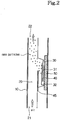
- FIG. 2 is a view illustrating a nano particle generator according to a second example.
- the body 10 of the nano particle generator is vertically disposed, and therefore, the channel 20 is formed in the vertical direction.
- the inlet 21 of the channel 20 is disposed at the lower end of the body 10, and the outlet 22 of the channel 20 is disposed at the upper end of the body 10. Consequently, a fluid flows from the bottom of the body 10 to the top of the body 10.
- the heating unit 30 is supported by the insulating member 50 only at the lower end thereof, and the heating unit 30 is spaced apart from the insulating member 50 at the upper end thereof. Consequently, the contact area between the heating unit 30 and the insulating member 50 is minimized.
- the lower end of the heating unit 30 is supported by the insulating member 50 as described above, gravity is applied to the lower end of the heating unit 30, and therefore, the heating unit 30 is stably supported.
- the material 40 cannot be located in the locating part 31 of the heating unit 30 when the material 40 is a powdered material. Consequently, it is preferable to coat the material 40 on the locating part 31 or to sinter and locate the material in the locating part 31.
- FIG. 3 is a view illustrating a nano particle generator according to a third example.
- the nano particle generator does not include a partition plate to partition the channel 20 and the heating unit 30 from each other.
- the nano particle generator is constructed such that a fluid can flow along the channel at more than a predetermined speed.
- the straight movability of the fluid is increased, and therefore, the fluid flowing along the channel 20 does not directly contact the heating unit even without the provision of the partition plate.
- the fluid, such as air, flowing along the channel 20 forms an insulating layer without the provision of the partition plate, and therefore, it is possible to prevent heat generated from the heating unit 30 from being transmitted to the body 10.
- FIG. 4 is a view illustrating a nano particle generator according to a first embodiment of the present invention.
- the channel 20 is partitioned into two channels 20a and 20b by the insulating member 50 and the heating unit 30.
- a fluid flows along the channels 20a and 20b from the bottom of body 10 to the top of the body 10.
- locating parts 31a and 31b are formed at opposite sides of the heating unit 30 such that materials 40a and 40b can be evaporated by the fluid flowing along the channels 20a and 20b.
- the materials 40a and 40b are located in the locating parts 31a and 31b, respectively.
- partition plates 45a and 45b between the respective channels 20a and 20b and the heating unit 30 are disposed partition plates 45a and 45b, by which the fluid flowing along the channels 20a and 20b does not directly contact the heating unit 30, and therefore, heat generated from the heating unit is prevented from being transmitted to the body 10.
- FIG. 5 is a view illustrating a nano particle generator according to a second embodiment of the present invention.
- no partition plates are disposed between the respective channels 20a and 20b and the heating unit 30.
- the nano particle generator is constructed such that a fluid can flow along the respective channels at more than a predetermined speed.
- the straight movability of the fluid is increased, and therefore, the fluid flowing along the channel 20 does not directly contact the heating unit. As such, it is possible to prevent heat generated from the heating unit 30 from being transmitted to the body 10.
- FIG. 6 is a view illustrating a nano particle generator according to a third embodiment of the present invention.
- a heating wire (not shown) mounted in the heating unit 30 is concentrated at one end of the heating unit 30, and therefore, the heating unit 30 has temperature distribution as shown in the drawing. Consequently, it is possible to prevent the insulating member 50, which supports the heating unit 30, from being damaged due to the high-temperature heating unit 30.
- the materials 40a and 40b are located in the highest-temperature regions of the heating unit 30.
- the locating parts 31a and 31b are formed in the heating unit 30 such that the materials 40a and 40b are located in the locating parts 31a and 31b.
- the materials 40a and 40b are heated by the heating unit 30, the materials 40a and 40b are changed from a solid phase to a liquid phase.
- the liquid-phase materials are evaporated into a gas phase.
- the locating parts 31a and 31b are formed in the shape of a groove such that the materials 40a and 40b are not separated from the locating parts when the materials 40a and 40b are changed into the gas phase.
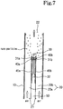
- FIG. 7 is a view illustrating a nano particle generator according to a fourth embodiment of the present invention.
- the nano particle generator includes partition plates 45a and 45b disposed between the heating unit 30 and the body 10.
- the partition plates 45a and 45b are mounted to cover the highest-temperature regions of the heating unit 30 such that a radiant heat generated from the highest-temperature regions of the heating unit 30 is not transmitted to the body 10.
- FIGS. 8A and 8B are view illustrating a nano particle generator according to an fifth embodiment of the present invention.
- a plurality of locating parts 31a, 31b, 31c, and 31d are formed in the highest-temperature regions of the heating unit 30. Consequently, when the nano particle generator is operated after the same material is located in the locating parts 31a, 31b, 31c, and 31d, it is possible to generate a large amount of nano particles at a time.
- FIG. 9 is a view illustrating a heating unit and a power supply unit, which supplies power to the heating unit, of a nano particle generator according to a sixth embodiment of the present invention.
- Other components of the nano particle generator according to the sixth embodiment are identical to those of the nano particle generator shown in FIGS. 8A and 8B .
- the nano particle generator includes a heating unit 30 having a plurality of locating parts 31 formed in the upper part thereof to receive different materials, a power supply unit 60 to supply power to the heating unit 30, and a wire 61 to connect the power supply unit 60 and the heating unit 30.
- the heating unit 30 includes a plate-shaped heating body 35, which is made of ceramic, and a heating wire 36 buried in the heating body 35 to generate heat when the heating unit 30 is supplied with power.
- the heating wire 36 is made of tungsten. The reason why the heating wire 36 is buried in the heating body 35 is to prevent the heating wire 36 from being corroded by a fluid flowing along the channel 20.
- the heating wire 36 is bent several times in the heating body 35 in a serpentine fashion. Consequently, it is possible to evaporate the materials located in the heating unit 30 in short time.
- the locating parts 31, in which the materials are located are formed along a course in which the heating wire 36 extends. Different materials are located in the respective locating parts 31a, 31b, 31c, and 31d. The materials are evaporated at the same time, and therefore, nano particles having all characteristics of the respective materials are generated.
- the evaporation temperatures for the respective materials are different from each other. Consequently, the locating parts 31a, 31b, 31c, and 31d must be heated to temperatures at which the respective materials are evaporated in the same time in order that nano particles are generated at the same time when the respective materials are heated.
- a material is heated by the heating unit of the nano particle generator while being in direct contact with the heating unit, and the contact area between the heating unit and the insulating member is minimized. Consequently, it is possible to generate nano particles in short time while power consumption is reduced.
Description
- The present invention relates to a nano particle generator, and, more particularly, to a nano particle generator that can reduce power consumption, can be miniaturized, and can generate nano particles having various different material characteristics at the same time.
- Generally, a nano particle is an ultramicroscopic particle having a size of 1 nm to 100 nm. The nano particle has unique physical and chemical characteristics depending upon the size of the particle and the properties of a material.
- Recently, continuous attempts have been made to generate nano particles from a material having bactericidal and antibacterial properties, such as gold and silver, or a material having toxic gas adsorption, such as titanium dioxide, thereby achieving bactericidal and antibacterial activities against biological pollutants and removing toxic gases, such as volatile organic compounds (VOC) and ozone by absorption.
- An example of a method of generating nano particles is a gas condensing method in which a material is evaporated by heating, and the evaporated gas is condensed to generate nano particles. A conventional nano particle generator for generating nano particles using the gas condensing method will be described below.
- The conventional nano particle generator includes a body formed in the shape of an electric heating furnace to maintain high temperature, a tube extending through the body, a container disposed in the center of the tub to receive a material from which nano particles are to be formed, and a heating body mounted between inner and outer walls of the body at the region corresponding to the container.
- When the heating body is heated while a fluid, such as air, flows along the tube of the nano particle generator with the above-stated construction, the interior temperature of the body is increased. As a result, the tube is heated, and therefore, the interior temperature of the tube is increased. When the temperature applied to the material exceeds a predetermined temperature level, the material is evaporated with the result that gas is generated from the material. The gas is condensed by the fluid flowing along the tube to generate nano particles. The generated nano particles are discharged out of the body along with the fluid.
- When the temperature of the electric heating furnace, the flow rate of the fluid flowing along the tube, and the size of the container to receive the material are controlled in the nano particle generator with the above-stated construction, it is possible to generate nano particles having a size of 1 to 100 nm and a concentration of 106 to 108/cm2.
- In the conventional nano particle generator that generates nano particles using the gas condensing method, however, the interior temperature of the body, which has a large space, must be increased to from several hundred degrees to several thousand degrees. As a result, power consumption is increased.
- Also, a large space is needed between the heating body and the material. As a result, it is difficult to reduce the size of the nano particle generator.
- Furthermore, several materials having different evaporation temperatures cannot be evaporated at the same time in a single nano particle generator. As a result, it is not possible to generate nano particles having various characteristics.
-
US 2003,115 986 discloses a nano particle generator with the features of the precharacterizing part of claim 1. According to this reference a type of process for the manufacturing of metal nano particles is disclosed. The apparatus comprises a furnace with a housing or body, a heating unit, see corresponding electrode, with crucible for receiving the material to be evaporated. The material is a metal that is heated by a current through the electrode. The crucible is some type of locating part that is formed within the heating unit and the material is located therein. An inlet tube is used for supplying gas from the outside. This non-reactive gas is introduced into the furnace to envelope and assist in the formation of the fine particles and to facilitate their transportation through a transfer tube to a collection vessel. - It is an object of the present invention to provide a nano particle generator that heats a material to generate nano particles with reduced power consumption and which simultaneously prevents heat generated from the heating unit from being discharged out of the body.
- This object is solved by the features of claim 1.
- The nano particle generator can further comprise: a partition plate to partition the channel and the heating unit such that the fluid flowing along the channel does not directly contact the heating unit.
- The channel may be vertically disposed, and only the lower end of the heating unit can be supported by the insulating member.
- The channel is divided into two channels about the heating unit, and two or more locating parts are formed on opposite sides of the heating unit. The material may be coated on the locating part or located in the locating part after the material is sintered.
- It is possible to form the locating part in the shape of a groove such that the material is not separated from the locating part even when the phase of the material is changed.
- The heating unit can have a locating part formed in the highest-temperature region thereof such that the material is located in the locating part.
- The same material can be located in the locating parts. Alternatively, different materials may be located in the locating parts, and the locating parts can be heated to temperatures at which the respective materials are evaporated in the same time.
- The heating unit may comprise a heating body having a plurality of locating parts formed therein and a heating wire buried in the heating body to heat the locating parts. The resistance of the heating wire buried around the respective locating parts can be changed such that the locating parts are heated to different temperatures, in particular in the same line.
- It can be considered as advantageous when the heating unit is spaced apart from an inner surface of the channel in a longitudinal direction of the channel.
- The heating unit may further be disposed in the channel such that an evaporation direction of the material evaporated by the heating unit is parallel to a flow direction of the fluid in the channel.
- Additional aspects and/or advantages of the invention will be set forth in part in the description which follows and, in part, will be obvious from the description, or may be learned by practice of the invention.
- These and/or other aspects and advantages of the invention will become apparent and more readily appreciated from the following description of the embodiments, taken in conjunction with the accompanying drawings, of which:
-
FIG. 1 is a view illustrating a nano particle generator according to a first example; -
FIG. 2 is a view illustrating a nano particle generator according to a second example; -
FIG. 3 is a view illustrating a nano particle generator according to a third example; -
FIG. 4 is a view illustrating a nano particle generator according to a first embodiment of the present invention; -
FIG. 5 is a view illustrating a nano particle generator according to a second embodiment of the present invention; -
FIG. 6 is a view illustrating a nano particle generator according to a third embodiment of the present invention; -
FIG. 7 is a view illustrating a nano particle generator according to a fourth embodiment of the present invention; -
FIGS. 8A and8B are views illustrating a nano particle generator according to an fifth embodiment of the present invention; and -
FIG. 9 is a view illustrating a heating unit of a nano particle generator according to a sixth embodiment of the present invention. - Reference will now be made in detail to the embodiment of the present invention, examples of which are illustrated in the accompanying drawings, wherein like reference numerals refer to like elements throughout. The embodiment is described below to explain the present invention by referring to the figures.
-
FIG. 1 is a view illustrating a nano particle generator according to a first example. - As shown in
FIG. 1 , the nano particle generator includes abody 10 constituting the external appearance thereof, achannel 20 formed in the upper part of thebody 10, such that thechannel 20 extends in the lateral direction of thebody 10, to allow a fluid to flow therethrough, and aheating unit 30 mounted in the lower part of thebody 10 to heat amaterial 40. - Also, a blowing fan (not shown) is mounted to provide a blowing force, by which the fluid is supplied into the
channel 20 through aninlet 21 of thechannel 20 and nano particles generated from thematerial 40 heated by theheating unit 30 are discharged out of thebody 10. - The
heating unit 30, which is disposed below thechannel 20, heats thematerial 40, from which the nano particles are to be generated, while theheating unit 30 is in direct contact with thematerial 40. When theheating unit 30 heats thematerial 40 while theheating unit 30 is in direct contact with thematerial 40, i.e., in a direct heating fashion, it is possible to heat thematerial 40 to a temperature at which thematerial 40 is evaporated in short time, and therefore, the power consumption is reduced. Also, no space is necessary between theheating unit 30 and thematerial 40, and therefore, the size of the nano particle generator is reduced. - In the upper part of the
heating unit 30 is formed a locatingpart 31 depressed at the center thereof such that the material 40 can be located in the locatingpart 31. Consequently, it is possible to locate the material 40 in the locatingpart 31 even though thematerial 40 is a powdered material. - Under the
heating unit 30 is disposed an insulatingmember 50 to support theheating unit 30 and prevent heat generated from the heating unit from being discharged out of thebody 10. The heat generated from theheating unit 30 intensively heats thematerial 40 due to the insulatingmember 50, and therefore, it is possible to evaporate the material 40 in short time. Furthermore, when the nano particle generator is mounted in electric home appliances, the electric home appliances are prevented from being damaged due to heat generated from theheating unit 30. - A supporting
part 32 of theheating unit 30, at which theheating unit 30 is supported by the insulatingmember 50, is in contact with the insulatingmember 50 at opposite ends thereof such that the supportingpart 32 is in contact with the insulating member over the minimum area. The center of the supportingpart 32 is spaced apart from the insulatingmember 50. Consequently, the supportingmember 32 is in point or line contact with the insulatingmember 50. This is because, if the contact area between theheating unit 30 and the insulatingmember 50 is large, a large amount of heat generated from theheating unit 30 is transmitted to the insulatingmember 50, and therefore, is takes plenty of time to heat and evaporate thematerial 40. - Between the
channel 20 and theheating unit 30 is mounted apartition plate 45 to partition thechannel 20 and theheating unit 30 from each other such that the fluid flowing along thechannel 20 is not brought into direct contact with theheating unit 30. If the fluid flowing along thechannel 20 directly contacts theheating unit 30, the temperature of the heating unit may be reduced by low-temperature fluid at the time of heating theheating unit 30. Thepartition plate 45 is provided to prevent such lowering of the temperature of theheating unit 30. Also, thepartition plate 45 is provided to partially interrupt a radiant heat generated from theheating unit 30, when theheating unit 30 is heated to high temperature, from being transmitted to the upper part of thebody 10, in which the insulatingmember 50 is not mounted, and thus, to prevent thebody 10 from being heated. Consequently, it is preferable to make thepartition plate 45 of a material that can be deformed at high temperature. - When the temperature of the
heating unit 30, which has a heating wire (not shown) mounted therein, is increased in the nano particle generator with the above-described construction, the temperature of the material 40 contacting theheating unit 30 is increased to an evaporation temperature. When thematerial 40 is heated to more than the evaporation temperature, the surface of the material 40 facing thechannel 20 is evaporated. - The evaporated material is drawn to the
channel 20, which has relatively low pressure, due to the fluid flowing along thechannel 20, and is instantaneously cooled by the low-temperature fluid into solid particles of a nanometer size. The generated nano particles are discharged through anoutlet 22 of thechannel 20 together with the surrounding fluid, and are then injected to a desired area through a connection pipe (not shown). -
FIG. 2 is a view illustrating a nano particle generator according to a second example. - As shown in
FIG. 2 , thebody 10 of the nano particle generator is vertically disposed, and therefore, thechannel 20 is formed in the vertical direction. Theinlet 21 of thechannel 20 is disposed at the lower end of thebody 10, and theoutlet 22 of thechannel 20 is disposed at the upper end of thebody 10. Consequently, a fluid flows from the bottom of thebody 10 to the top of thebody 10. In this embodiment, theheating unit 30 is supported by the insulatingmember 50 only at the lower end thereof, and theheating unit 30 is spaced apart from the insulatingmember 50 at the upper end thereof. Consequently, the contact area between theheating unit 30 and the insulatingmember 50 is minimized. Although the lower end of theheating unit 30 is supported by the insulatingmember 50 as described above, gravity is applied to the lower end of theheating unit 30, and therefore, theheating unit 30 is stably supported. - In this embodiment, the
material 40 cannot be located in the locatingpart 31 of theheating unit 30 when thematerial 40 is a powdered material. Consequently, it is preferable to coat thematerial 40 on the locatingpart 31 or to sinter and locate the material in the locatingpart 31. -
FIG. 3 is a view illustrating a nano particle generator according to a third example. - In this embodiment, the nano particle generator does not include a partition plate to partition the
channel 20 and theheating unit 30 from each other. - Instead, the nano particle generator is constructed such that a fluid can flow along the channel at more than a predetermined speed. In this case, the straight movability of the fluid is increased, and therefore, the fluid flowing along the
channel 20 does not directly contact the heating unit even without the provision of the partition plate. Also, the fluid, such as air, flowing along thechannel 20 forms an insulating layer without the provision of the partition plate, and therefore, it is possible to prevent heat generated from theheating unit 30 from being transmitted to thebody 10. -
FIG. 4 is a view illustrating a nano particle generator according to a first embodiment of the present invention. - In this embodiment, the
channel 20 is partitioned into twochannels member 50 and theheating unit 30. A fluid flows along thechannels body 10 to the top of thebody 10. Also, locatingparts heating unit 30 such thatmaterials channels materials parts respective channels heating unit 30 are disposedpartition plates channels heating unit 30, and therefore, heat generated from the heating unit is prevented from being transmitted to thebody 10. -
FIG. 5 is a view illustrating a nano particle generator according to a second embodiment of the present invention. - In this embodiment, no partition plates are disposed between the
respective channels heating unit 30. - Instead, the nano particle generator is constructed such that a fluid can flow along the respective channels at more than a predetermined speed. In this case, the straight movability of the fluid is increased, and therefore, the fluid flowing along the
channel 20 does not directly contact the heating unit. As such, it is possible to prevent heat generated from theheating unit 30 from being transmitted to thebody 10. -
FIG. 6 is a view illustrating a nano particle generator according to a third embodiment of the present invention. - In this embodiment, a heating wire (not shown) mounted in the
heating unit 30 is concentrated at one end of theheating unit 30, and therefore, theheating unit 30 has temperature distribution as shown in the drawing. Consequently, it is possible to prevent the insulatingmember 50, which supports theheating unit 30, from being damaged due to the high-temperature heating unit 30. - On the other hand, the
materials heating unit 30. As a result, when the nano particle generator is operated, the evaporation speed of thematerials parts heating unit 30 such that thematerials parts materials heating unit 30, thematerials parts materials materials -
FIG. 7 is a view illustrating a nano particle generator according to a fourth embodiment of the present invention. - In this embodiment, the nano particle generator includes
partition plates heating unit 30 and thebody 10. In this case, thepartition plates heating unit 30 such that a radiant heat generated from the highest-temperature regions of theheating unit 30 is not transmitted to thebody 10. -
FIGS. 8A and8B are view illustrating a nano particle generator according to an fifth embodiment of the present invention. A plurality of locatingparts heating unit 30. Consequently, when the nano particle generator is operated after the same material is located in the locatingparts -
FIG. 9 is a view illustrating a heating unit and a power supply unit, which supplies power to the heating unit, of a nano particle generator according to a sixth embodiment of the present invention. Other components of the nano particle generator according to the sixth embodiment are identical to those of the nano particle generator shown inFIGS. 8A and8B . - In this embodiment, the nano particle generator includes a
heating unit 30 having a plurality of locatingparts 31 formed in the upper part thereof to receive different materials, apower supply unit 60 to supply power to theheating unit 30, and awire 61 to connect thepower supply unit 60 and theheating unit 30. - The
heating unit 30 includes a plate-shapedheating body 35, which is made of ceramic, and aheating wire 36 buried in theheating body 35 to generate heat when theheating unit 30 is supplied with power. Theheating wire 36 is made of tungsten. The reason why theheating wire 36 is buried in theheating body 35 is to prevent theheating wire 36 from being corroded by a fluid flowing along thechannel 20. - The
heating wire 36 is bent several times in theheating body 35 in a serpentine fashion. Consequently, it is possible to evaporate the materials located in theheating unit 30 in short time. - The locating
parts 31, in which the materials are located, are formed along a course in which theheating wire 36 extends. Different materials are located in therespective locating parts - However, the evaporation temperatures for the respective materials are different from each other. Consequently, the locating
parts - In order to heat the locating
parts heating wire 36 buried around therespective locating parts heating wire 36 is easily changed by changing the thickness of theheating wire 36 extending around therespective locating parts - As the different materials are evaporated at the same time as described above, nano particles having all characteristics of the respective materials are generated.
- As apparent from the above description, a material is heated by the heating unit of the nano particle generator while being in direct contact with the heating unit, and the contact area between the heating unit and the insulating member is minimized. Consequently, it is possible to generate nano particles in short time while power consumption is reduced.
- Also, no large space is necessary between the heating unit and the material. Consequently, it is possible to reduce the size of the nano particle generator.
- Furthermore, several different materials are evaporated at the same time to generate nano particles. Consequently, it is possible to generate nano particles having all characteristics of the respective materials.
Claims (16)
- A nano particle generator comprising: a body (10); a heating unit (30); a material (40, 40a, 40b) received in the body (10) to be evaporated by heating by the heating unit (30), and a channel (20, 20a, 20b) extending through the body (10) such that the fluid to condense the evaporated material flows along the channel, wherein the heating unit (30) comprises at least one locating part (31, 31a, 31b) formed therein such that the material is located in the locating part, characterized by further comprising an insulating member (50) supporting the heating unit (30),
wherein the insulating member (50) and the heating unit (30) are arranged one after the other in flow direction of the flow with the heating unit (30) downstream of the insulating member (50), and
the channel (20) is divided into two channels (20a, 20b) about the heating unit (30),
wherein at least two or more locating parts (31, 31a, 31b) are formed on opposite sides of the heating unit (30). - The nano particle generator according to claim 1, wherein the heating unit (30) is spaced apart from an inner surface of the channel in a direction perpendicular to a longitudinal direction of the channel.
- The nano particle generator according to claim 2, wherein the longitudinal direction of the channel intersects the evaporation direction of gas evaporated from the material.
- The nano particle generator according to one of the previous claims, wherein the at least two or more locating parts (31, 31a, 31b) for locating the same material or different materials in the locating parts are provided.
- The nano particle generator according to one of the previous claims, wherein the locating part or parts (31, 31a, 31b) is or are formed in the highest-temperature region of the heating unit (30).
- The nano particle generator according to one of the previous claims, wherein the body (10) is vertically disposed and only a lower end of the heating unit (30) is supported by the insulating member (50).
- The nano particle generator according to one of the previous claims, wherein the material (40, 40a, 40b) is coated on the locating part or is located in the locating part after the material is sintered.
- The nano particle generator according to one of the previous claims, wherein the locating part is formed in the shape of a groove.
- The nano particle generator according to one of the previous claims, wherein the heating unit (30) includes a heating body (35) and at least one heating wire (61) buried in the heating body (35) to heat the locating parts (31, 31a-d).
- The nano particle generator according to claim 9, wherein the resistance of the heating wire (61) buried around the respective locating parts (31, 31a-d) is changed to heat different locating parts to different temperatures.
- The nano particle generator according to claim 1, wherein two partition plates (45, 45a, 45b) are disposed between the heating unit (30) and the body (10).
- The nano particle generator according to claims 9 to 11, wherein the heating wire (61) is concentrated at an end of the heating unit (30).
- The nano particle generator according toclaim 12, wherein a partition plate (45, 45a, 45b) covers the highest-temperature region of the heating unit (30).
- The nano particle generator according to one of the previous claims, wherein the heating body (35) is plate-shaped.
- The nano particle generator according to claim 9 or 10, wherein the heating wire (61) is bent several times in the heating body (35) in particular in a serpentine fashion.
- The nano particle generator according to claim 15, wherein the location parts (31, 31a-d) are formed along a course in which the heating wire (36) extends.
Applications Claiming Priority (2)
| Application Number | Priority Date | Filing Date | Title |
|---|---|---|---|
| KR1020050077409A KR100857596B1 (en) | 2005-08-23 | 2005-08-23 | Nano particle generator |
| EP06119300A EP1757359B1 (en) | 2005-08-23 | 2006-08-22 | Nano particle generator |
Related Parent Applications (1)
| Application Number | Title | Priority Date | Filing Date |
|---|---|---|---|
| EP06119300A Division EP1757359B1 (en) | 2005-08-23 | 2006-08-22 | Nano particle generator |
Publications (3)
| Publication Number | Publication Date |
|---|---|
| EP2016998A2 EP2016998A2 (en) | 2009-01-21 |
| EP2016998A3 EP2016998A3 (en) | 2009-02-25 |
| EP2016998B1 true EP2016998B1 (en) | 2017-11-29 |
Family
ID=37460031
Family Applications (2)
| Application Number | Title | Priority Date | Filing Date |
|---|---|---|---|
| EP06119300A Expired - Fee Related EP1757359B1 (en) | 2005-08-23 | 2006-08-22 | Nano particle generator |
| EP08017972.4A Active EP2016998B1 (en) | 2005-08-23 | 2006-08-22 | Nano particle generator |
Family Applications Before (1)
| Application Number | Title | Priority Date | Filing Date |
|---|---|---|---|
| EP06119300A Expired - Fee Related EP1757359B1 (en) | 2005-08-23 | 2006-08-22 | Nano particle generator |
Country Status (6)
| Country | Link |
|---|---|
| US (2) | US7863545B2 (en) |
| EP (2) | EP1757359B1 (en) |
| JP (2) | JP4542069B2 (en) |
| KR (1) | KR100857596B1 (en) |
| CN (2) | CN100567139C (en) |
| DE (1) | DE602006003147D1 (en) |
Families Citing this family (8)
| Publication number | Priority date | Publication date | Assignee | Title |
|---|---|---|---|---|
| US7750270B2 (en) * | 2004-12-28 | 2010-07-06 | Samsung Electronics Co., Ltd. | Nanoparticle generator |
| KR100857596B1 (en) | 2005-08-23 | 2008-09-09 | 삼성전자주식회사 | Nano particle generator |
| KR101149408B1 (en) * | 2006-11-15 | 2012-06-01 | 삼성전자주식회사 | Method and apparatus for manufacturing electrode of fuel cell |
| CN103011055B (en) * | 2012-11-28 | 2015-07-15 | 苏州大学 | Microparticle production device and production method |
| KR20150114290A (en) * | 2014-04-01 | 2015-10-12 | 주식회사 에코픽쳐스 | Nano particle generator |
| FI20165251A (en) * | 2016-03-24 | 2017-09-25 | Univ Helsinki | Process and arrangement for verification, optimization or calibration of a particle detector |
| KR102331341B1 (en) | 2020-04-29 | 2021-11-24 | 경희대학교 산학협력단 | Method and apparatus for generating conductive nano particle |
| CN111721495B (en) * | 2020-06-16 | 2022-02-08 | 中国人民解放军国防科技大学 | Novel particle of nano particle plane laser scattering experiment generates device |
Family Cites Families (40)
| Publication number | Priority date | Publication date | Assignee | Title |
|---|---|---|---|---|
| US3452970A (en) * | 1967-05-12 | 1969-07-01 | Siemens Ag | Vaporization vessel for use in vapor deposition upon a carrier support |
| US3949743A (en) * | 1973-03-19 | 1976-04-13 | Schick Incorporated | Medicated vapor production method and apparatus |
| JPS59162204A (en) * | 1983-03-04 | 1984-09-13 | Tanaka Kikinzoku Kogyo Kk | Method and device for ultrafine powder |
| US5038769A (en) * | 1983-06-29 | 1991-08-13 | Krauser Robert S | Method and apparatus for treating ailments |
| JPS6018902A (en) * | 1983-07-13 | 1985-01-31 | Toyota Motor Corp | Preparation of magnetic fluid |
| US4690813A (en) * | 1984-09-14 | 1987-09-01 | Alps Electric Co., Ltd. | Molybdenum oxide whiskers and a method of producing the same |
| JPS61257468A (en) * | 1985-05-08 | 1986-11-14 | Ishikawajima Harima Heavy Ind Co Ltd | Crucible for evaporating metallic atom |
| JPS62168542A (en) * | 1986-01-21 | 1987-07-24 | Daido Steel Co Ltd | Production of ultrafine particulate compound |
| US4735217A (en) * | 1986-08-21 | 1988-04-05 | The Procter & Gamble Company | Dosing device to provide vaporized medicament to the lungs as a fine aerosol |
| US4718124A (en) * | 1987-01-13 | 1988-01-12 | Sawicki Marsha M | Patient gown |
| JPH062225B2 (en) * | 1988-11-12 | 1994-01-12 | 真空冶金株式会社 | Ultrafine organic substance manufacturing equipment |
| US4917119A (en) * | 1988-11-30 | 1990-04-17 | R. J. Reynolds Tobacco Company | Drug delivery article |
| FI84357C (en) * | 1989-10-20 | 1991-11-25 | Neste Oy | Process and apparatus for preparing polymerization catalyst supports |
| US5144962A (en) * | 1989-12-01 | 1992-09-08 | Philip Morris Incorporated | Flavor-delivery article |
| JPH0763618B2 (en) * | 1989-12-04 | 1995-07-12 | 工業技術院長 | Ultrafine particle manufacturing method |
| US5264681A (en) * | 1991-02-14 | 1993-11-23 | Ngk Spark Plug Co., Ltd. | Ceramic heater |
| US5249586A (en) * | 1991-03-11 | 1993-10-05 | Philip Morris Incorporated | Electrical smoking |
| US5388574A (en) * | 1993-07-29 | 1995-02-14 | Ingebrethsen; Bradley J. | Aerosol delivery article |
| US5456247A (en) * | 1993-08-26 | 1995-10-10 | Iowa State University Research Foundation, Inc. | Method for delivering drugs soluble in a vaporization vehicle |
| US6102036A (en) * | 1994-04-12 | 2000-08-15 | Smoke-Stop | Breath activated inhaler |
| US5514350A (en) * | 1994-04-22 | 1996-05-07 | Rutgers, The State University Of New Jersey | Apparatus for making nanostructured ceramic powders and whiskers |
| US5575941A (en) * | 1994-08-31 | 1996-11-19 | Johnson; J. Evan | Cartridge heater |
| US5522385A (en) * | 1994-09-27 | 1996-06-04 | Aradigm Corporation | Dynamic particle size control for aerosolized drug delivery |
| US5537507A (en) * | 1994-09-28 | 1996-07-16 | Advanced Ceramics Corporation | Coated flash evaporator heater |
| JPH0889938A (en) * | 1994-09-28 | 1996-04-09 | Showa Denko Kk | Treatment of water-based liquid containing hydrogen peroxide |
| US5472749A (en) * | 1994-10-27 | 1995-12-05 | Northwestern University | Graphite encapsulated nanophase particles produced by a tungsten arc method |
| US6694975B2 (en) * | 1996-11-21 | 2004-02-24 | Aradigm Corporation | Temperature controlling device for aerosol drug delivery |
| US5946722A (en) * | 1997-05-28 | 1999-09-07 | Trautmann; Charlotte B. | Patient privacy gown |
| US5958329A (en) * | 1997-11-06 | 1999-09-28 | United States Enrichment Corporation | Method and apparatus for producing nanoparticles at a high rate |
| KR20010099547A (en) * | 2000-04-27 | 2001-11-09 | 허승헌 | A design of a nanometer size metal, nonmetal, and alloy particle generator |
| US6468497B1 (en) * | 2000-11-09 | 2002-10-22 | Cyprus Amax Minerals Company | Method for producing nano-particles of molybdenum oxide |
| US6381408B1 (en) * | 2001-07-31 | 2002-04-30 | S. C. Johnson & Son, Inc. | Electric fumigator |
| WO2003057188A1 (en) * | 2001-11-21 | 2003-07-17 | Alexza Molecular Delivery Corporation | Delivery of caffeine through an inhalation route |
| US6688494B2 (en) * | 2001-12-20 | 2004-02-10 | Cima Nanotech, Inc. | Process for the manufacture of metal nanoparticle |
| US20030126668A1 (en) * | 2002-01-10 | 2003-07-10 | Scroggins Georgia W. | Hospital dressing gown construction |
| US7913688B2 (en) * | 2002-11-27 | 2011-03-29 | Alexza Pharmaceuticals, Inc. | Inhalation device for producing a drug aerosol |
| KR20050055079A (en) * | 2003-12-04 | 2005-06-13 | 최순림 | Nanofluids one-step manufacturing equipment |
| US7384448B2 (en) * | 2004-02-16 | 2008-06-10 | Climax Engineered Materials, Llc | Method and apparatus for producing nano-particles of silver |
| US7750270B2 (en) * | 2004-12-28 | 2010-07-06 | Samsung Electronics Co., Ltd. | Nanoparticle generator |
| KR100857596B1 (en) | 2005-08-23 | 2008-09-09 | 삼성전자주식회사 | Nano particle generator |
-
2005
- 2005-08-23 KR KR1020050077409A patent/KR100857596B1/en active IP Right Grant
-
2006
- 2006-08-22 EP EP06119300A patent/EP1757359B1/en not_active Expired - Fee Related
- 2006-08-22 JP JP2006225643A patent/JP4542069B2/en not_active Expired - Fee Related
- 2006-08-22 EP EP08017972.4A patent/EP2016998B1/en active Active
- 2006-08-22 DE DE602006003147T patent/DE602006003147D1/en active Active
- 2006-08-23 CN CNB2006101216329A patent/CN100567139C/en not_active Expired - Fee Related
- 2006-08-23 US US11/508,319 patent/US7863545B2/en active Active
- 2006-08-23 CN CN2009100021204A patent/CN101486440B/en not_active Expired - Fee Related
-
2008
- 2008-12-23 US US12/318,277 patent/US8895900B2/en active Active
-
2009
- 2009-02-04 JP JP2009023674A patent/JP5508731B2/en not_active Expired - Fee Related
Non-Patent Citations (1)
| Title |
|---|
| None * |
Also Published As
| Publication number | Publication date |
|---|---|
| JP5508731B2 (en) | 2014-06-04 |
| CN101486440A (en) | 2009-07-22 |
| CN101486440B (en) | 2012-01-11 |
| EP1757359B1 (en) | 2008-10-15 |
| EP1757359A1 (en) | 2007-02-28 |
| US20070045291A1 (en) | 2007-03-01 |
| EP2016998A3 (en) | 2009-02-25 |
| EP2016998A2 (en) | 2009-01-21 |
| KR20070023137A (en) | 2007-02-28 |
| DE602006003147D1 (en) | 2008-11-27 |
| KR100857596B1 (en) | 2008-09-09 |
| JP2007054832A (en) | 2007-03-08 |
| CN1919721A (en) | 2007-02-28 |
| US20090127252A1 (en) | 2009-05-21 |
| US8895900B2 (en) | 2014-11-25 |
| JP4542069B2 (en) | 2010-09-08 |
| JP2009154153A (en) | 2009-07-16 |
| US7863545B2 (en) | 2011-01-04 |
| CN100567139C (en) | 2009-12-09 |
Similar Documents
| Publication | Publication Date | Title |
|---|---|---|
| EP2016998B1 (en) | Nano particle generator | |
| JP6133954B2 (en) | Method and apparatus to help promote contact between gas and evaporating material | |
| US20170029946A1 (en) | Method and apparatus to help promote contact of gas with vaporized material | |
| EP1923485B1 (en) | Vaporizer. | |
| WO1998031844A9 (en) | Flash evaporator | |
| US8554064B1 (en) | Method and apparatus for generating vapor at high rates | |
| WO1998031844A2 (en) | Flash evaporator | |
| US7750270B2 (en) | Nanoparticle generator | |
| JPH03168592A (en) | Scattering thin film heat-exchang- ing method and apparatus | |
| CN102016107A (en) | Heat equalizer and organic film forming apparatus | |
| JP4867722B2 (en) | Liquid concentrator | |
| KR20200087874A (en) | Improved ampoule evaporator and container | |
| CN111447982B (en) | Apparatus and method for vapor generation and thin film deposition | |
| KR100322411B1 (en) | Apparatus for vaporizing a liquid source | |
| EP1392429B1 (en) | A system for performing experiments, in particular for high throughput experimentation | |
| KR100665992B1 (en) | Nano particle generator | |
| JP2533811Y2 (en) | Gas phase chemical reactor for production of fine powder and ultra fine powder | |
| KR100896260B1 (en) | Nano particle generator | |
| KR100665994B1 (en) | Nano particle generator |
Legal Events
| Date | Code | Title | Description |
|---|---|---|---|
| PUAI | Public reference made under article 153(3) epc to a published international application that has entered the european phase |
Free format text: ORIGINAL CODE: 0009012 |
|
| 17P | Request for examination filed |
Effective date: 20081014 |
|
| AC | Divisional application: reference to earlier application |
Ref document number: 1757359 Country of ref document: EP Kind code of ref document: P |
|
| AK | Designated contracting states |
Kind code of ref document: A2 Designated state(s): DE FR GB |
|
| PUAL | Search report despatched |
Free format text: ORIGINAL CODE: 0009013 |
|
| AK | Designated contracting states |
Kind code of ref document: A3 Designated state(s): DE FR GB |
|
| 17Q | First examination report despatched |
Effective date: 20090509 |
|
| AKX | Designation fees paid |
Designated state(s): DE FR GB |
|
| RAP1 | Party data changed (applicant data changed or rights of an application transferred) |
Owner name: SAMSUNG ELECTRONICS CO., LTD. |
|
| GRAP | Despatch of communication of intention to grant a patent |
Free format text: ORIGINAL CODE: EPIDOSNIGR1 |
|
| INTG | Intention to grant announced |
Effective date: 20170622 |
|
| GRAS | Grant fee paid |
Free format text: ORIGINAL CODE: EPIDOSNIGR3 |
|
| GRAA | (expected) grant |
Free format text: ORIGINAL CODE: 0009210 |
|
| AC | Divisional application: reference to earlier application |
Ref document number: 1757359 Country of ref document: EP Kind code of ref document: P |
|
| AK | Designated contracting states |
Kind code of ref document: B1 Designated state(s): DE FR GB |
|
| REG | Reference to a national code |
Ref country code: GB Ref legal event code: FG4D |
|
| REG | Reference to a national code |
Ref country code: DE Ref legal event code: R096 Ref document number: 602006054244 Country of ref document: DE |
|
| REG | Reference to a national code |
Ref country code: FR Ref legal event code: PLFP Year of fee payment: 13 |
|
| REG | Reference to a national code |
Ref country code: DE Ref legal event code: R097 Ref document number: 602006054244 Country of ref document: DE |
|
| PLBE | No opposition filed within time limit |
Free format text: ORIGINAL CODE: 0009261 |
|
| STAA | Information on the status of an ep patent application or granted ep patent |
Free format text: STATUS: NO OPPOSITION FILED WITHIN TIME LIMIT |
|
| 26N | No opposition filed |
Effective date: 20180830 |
|
| PGFP | Annual fee paid to national office [announced via postgrant information from national office to epo] |
Ref country code: FR Payment date: 20210726 Year of fee payment: 16 |
|
| PGFP | Annual fee paid to national office [announced via postgrant information from national office to epo] |
Ref country code: GB Payment date: 20220720 Year of fee payment: 17 |
|
| PG25 | Lapsed in a contracting state [announced via postgrant information from national office to epo] |
Ref country code: FR Free format text: LAPSE BECAUSE OF NON-PAYMENT OF DUE FEES Effective date: 20220831 |
|
| PGFP | Annual fee paid to national office [announced via postgrant information from national office to epo] |
Ref country code: DE Payment date: 20230720 Year of fee payment: 18 |