EP2017917A2 - Software-implemented overcurrent protection embedded in a battery pack - Google Patents
Software-implemented overcurrent protection embedded in a battery pack Download PDFInfo
- Publication number
- EP2017917A2 EP2017917A2 EP08157591A EP08157591A EP2017917A2 EP 2017917 A2 EP2017917 A2 EP 2017917A2 EP 08157591 A EP08157591 A EP 08157591A EP 08157591 A EP08157591 A EP 08157591A EP 2017917 A2 EP2017917 A2 EP 2017917A2
- Authority
- EP
- European Patent Office
- Prior art keywords
- battery
- current
- switch
- control unit
- battery pack
- Prior art date
- Legal status (The legal status is an assumption and is not a legal conclusion. Google has not performed a legal analysis and makes no representation as to the accuracy of the status listed.)
- Granted
Links
- 229910001416 lithium ion Inorganic materials 0.000 description 10
- 229910052744 lithium Inorganic materials 0.000 description 3
- 230000001681 protective effect Effects 0.000 description 3
- WHXSMMKQMYFTQS-UHFFFAOYSA-N Lithium Chemical compound [Li] WHXSMMKQMYFTQS-UHFFFAOYSA-N 0.000 description 2
- 239000002253 acid Substances 0.000 description 2
- OJIJEKBXJYRIBZ-UHFFFAOYSA-N cadmium nickel Chemical compound [Ni].[Cd] OJIJEKBXJYRIBZ-UHFFFAOYSA-N 0.000 description 2
- 238000007599 discharging Methods 0.000 description 2
- 229910052987 metal hydride Inorganic materials 0.000 description 2
- 238000000034 method Methods 0.000 description 2
- 238000012544 monitoring process Methods 0.000 description 2
- 238000013021 overheating Methods 0.000 description 2
- 230000005355 Hall effect Effects 0.000 description 1
- HBBGRARXTFLTSG-UHFFFAOYSA-N Lithium ion Chemical compound [Li+] HBBGRARXTFLTSG-UHFFFAOYSA-N 0.000 description 1
- 239000000853 adhesive Substances 0.000 description 1
- 230000001070 adhesive effect Effects 0.000 description 1
- 230000002542 deteriorative effect Effects 0.000 description 1
- 238000010586 diagram Methods 0.000 description 1
- 238000005553 drilling Methods 0.000 description 1
- 239000003792 electrolyte Substances 0.000 description 1
- 238000011156 evaluation Methods 0.000 description 1
- 230000007257 malfunction Effects 0.000 description 1
- 238000005259 measurement Methods 0.000 description 1
- 229910052759 nickel Inorganic materials 0.000 description 1
- PXHVJJICTQNCMI-UHFFFAOYSA-N nickel Substances [Ni] PXHVJJICTQNCMI-UHFFFAOYSA-N 0.000 description 1
- -1 nickel metal hydride Chemical class 0.000 description 1
- 229920000642 polymer Polymers 0.000 description 1
- 238000012545 processing Methods 0.000 description 1
- 238000004904 shortening Methods 0.000 description 1
Images


Classifications
-
- H—ELECTRICITY
- H01—ELECTRIC ELEMENTS
- H01M—PROCESSES OR MEANS, e.g. BATTERIES, FOR THE DIRECT CONVERSION OF CHEMICAL ENERGY INTO ELECTRICAL ENERGY
- H01M10/00—Secondary cells; Manufacture thereof
- H01M10/42—Methods or arrangements for servicing or maintenance of secondary cells or secondary half-cells
- H01M10/4207—Methods or arrangements for servicing or maintenance of secondary cells or secondary half-cells for several batteries or cells simultaneously or sequentially
-
- H—ELECTRICITY
- H01—ELECTRIC ELEMENTS
- H01M—PROCESSES OR MEANS, e.g. BATTERIES, FOR THE DIRECT CONVERSION OF CHEMICAL ENERGY INTO ELECTRICAL ENERGY
- H01M10/00—Secondary cells; Manufacture thereof
- H01M10/42—Methods or arrangements for servicing or maintenance of secondary cells or secondary half-cells
- H01M10/425—Structural combination with electronic components, e.g. electronic circuits integrated to the outside of the casing
-
- H—ELECTRICITY
- H01—ELECTRIC ELEMENTS
- H01M—PROCESSES OR MEANS, e.g. BATTERIES, FOR THE DIRECT CONVERSION OF CHEMICAL ENERGY INTO ELECTRICAL ENERGY
- H01M10/00—Secondary cells; Manufacture thereof
- H01M10/42—Methods or arrangements for servicing or maintenance of secondary cells or secondary half-cells
- H01M10/44—Methods for charging or discharging
- H01M10/441—Methods for charging or discharging for several batteries or cells simultaneously or sequentially
-
- H—ELECTRICITY
- H01—ELECTRIC ELEMENTS
- H01M—PROCESSES OR MEANS, e.g. BATTERIES, FOR THE DIRECT CONVERSION OF CHEMICAL ENERGY INTO ELECTRICAL ENERGY
- H01M10/00—Secondary cells; Manufacture thereof
- H01M10/05—Accumulators with non-aqueous electrolyte
- H01M10/052—Li-accumulators
- H01M10/0525—Rocking-chair batteries, i.e. batteries with lithium insertion or intercalation in both electrodes; Lithium-ion batteries
-
- H—ELECTRICITY
- H01—ELECTRIC ELEMENTS
- H01M—PROCESSES OR MEANS, e.g. BATTERIES, FOR THE DIRECT CONVERSION OF CHEMICAL ENERGY INTO ELECTRICAL ENERGY
- H01M10/00—Secondary cells; Manufacture thereof
- H01M10/42—Methods or arrangements for servicing or maintenance of secondary cells or secondary half-cells
- H01M10/44—Methods for charging or discharging
- H01M10/448—End of discharge regulating measures
-
- Y—GENERAL TAGGING OF NEW TECHNOLOGICAL DEVELOPMENTS; GENERAL TAGGING OF CROSS-SECTIONAL TECHNOLOGIES SPANNING OVER SEVERAL SECTIONS OF THE IPC; TECHNICAL SUBJECTS COVERED BY FORMER USPC CROSS-REFERENCE ART COLLECTIONS [XRACs] AND DIGESTS
- Y02—TECHNOLOGIES OR APPLICATIONS FOR MITIGATION OR ADAPTATION AGAINST CLIMATE CHANGE
- Y02E—REDUCTION OF GREENHOUSE GAS [GHG] EMISSIONS, RELATED TO ENERGY GENERATION, TRANSMISSION OR DISTRIBUTION
- Y02E60/00—Enabling technologies; Technologies with a potential or indirect contribution to GHG emissions mitigation
- Y02E60/10—Energy storage using batteries
Definitions
- the present disclosure relates to a battery pack and, more particularly, to a software-implemented overcurrent protection mechanism embedded in a battery pack.
- Li-ion batteries have begun replacing nickel-cadmium (NiCd), nickel-metal-hydride (NiMH), and lead-acid batteries in low-voltage, portable electronic devices such as notebook-type personal computers.
- NiCd nickel-cadmium
- NiMH nickel-metal-hydride
- lead-acid batteries in low-voltage, portable electronic devices such as notebook-type personal computers.
- Li-ion batteries are lighter but have a larger capacity per unit volume.
- the Li-ion batteries are suitable to low-voltage devices that are preferably light and which are required to endure continuous use for a long time.
- a Li-ion battery pack may include functionality to protect against fault conditions inside and outside the Li-ion battery pack. This prevents cells in the Li-ion battery pack from deteriorating and shortening useful life of the pack. For instance, if a fault condition such as short-circuiting occurs inside or outside the Li-ion battery pack, a fuse may be provided to cut off an over-discharging current or an overcharging current, if the discharging current or charging current becomes larger than a given current level. However, a mechanical fuse needs to be replaced before the battery pack can be used again.
- a software-implemented fuse within in a battery pack.
- a software-implement protection mechanism enables the fuse to be tripped under different operating conditions.
- a software-implemented fuse may be reset after being tripped without intervention from a user.
- An overcurrent protection mechanism for a battery pack that may removably attaches to a power tool.
- the mechanism includes: one or more battery cells disposed in a battery pack; a current sensor configured to sense current supplied by the battery; a switch in a circuit path with the battery cells; and a battery control unit implemented as software instructions in a controller embedded in a battery pack.
- the battery control unit is configured to receive a signal indicative of current from the current sensor and control the switch to interrupt current flow from the battery cells as a function of current and time.
- the present disclosure can relate to a system of power tools of the type that is generally indicated by reference numeral 10 in Figure 1 .
- the system of power tools 10 can include, for example, one or more power tools 12, a battery pack 16 and a battery pack charger 18.
- Each of the power tools 12 can be any type of power tool, including without limitation drills, drill/drivers, hammer drill/drivers, rotary hammers, screwdrivers, impact drivers, circular saws, jig saws, reciprocating saws, band saws, cut-off tools, cut-out tools, shears, sanders, vacuums, lights, routers, adhesive dispensers, concrete vibrators, lasers, staplers and nailers.
- the system of power tools 10 includes a first power tool 12a and a second power tool 12b.
- the first power tool 12a can be a drill/driver similar to that which is described in U.S. Patent No. 6,431,289
- the second power tool 12b can be a circular saw similar to that which is described in U.S. Patent No. 6,996,909 .
- the battery pack 16 can be selectively removably coupled to the first and second power tools 12a and 12b to provide electrical power thereto. Except as otherwise described herein, the battery pack 16 can be configured in a manner that is similar to that which is described in U.S. Patent Application Publication No. 2006/0096771 .
- the battery pack 16 can also be selectively electrically coupled to the battery pack charger 18 to charge the battery pack 16. It is noteworthy that the broader aspects of this disclosure are applicable to other types of battery powered devices.
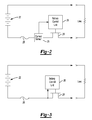
- FIG. 2 illustrates an exemplary circuit configuration for an overcurrent protection mechanism 20 integrated into a battery pack 16.
- the overcurrent protection mechanism 20 is comprised generally of battery cells 22, a switch 24 for controlling discharge of the battery cells, a current sensor 25, and a battery control unit 26.
- the overcurrent protection mechanism 20 may also include a fuse 28 placed in series with the battery cells.
- Each of these components is preferably integrated into the battery pack 16. However, it is envisioned that one or more of these components, excluding the battery cells, may be located in a battery charger, a power tool or some other external device operably coupled to the battery pack.
- the battery pack may include a plurality of battery cells 22 connected in series, and/or a plurality of serially-connected strings of cells, in which the strings are in parallel with one another.
- the battery pack may be composed of cells having lithium-ion cell chemistry.
- the nominal voltage rating of the battery pack is typically at least 18 volts. However, other voltage ratings are contemplated for different applications.
- the battery pack may be composed of cells of another lithium-based chemistry, such as lithium metal or lithium polymer, or other chemistry such as nickel cadmium (NiCd), nickel metal hydride (NiMH) and lead-acid, for example, in terms of the chemistry makeup of individual cells, electrodes and electrolyte of the pack.
- the battery pack 16 is preferably rechargeable.
- a battery control unit 26 embedded within the battery pack 16 is responsible for protecting the battery cells and monitoring any fault conditions which may develop.
- the battery control unit 16 is implemented in software on a digital microcontroller.
- the battery control unit 26 may be embodied in hardware or software as a digital microcontroller, a microprocessor or an analog circuit, a digital signal processor or by one or more digital ICs such as application specific integrated circuits (ASICs), for example.
- ASICs application specific integrated circuits
- Discharge current from the battery cells and charge current to the battery cells can be clamped or discontinued through the use of a switch 24.
- the switch 24 may be placed in series with the battery cells on the low voltage side of the battery cells. The switch 24 can then be controlled by the battery control unit to interrupt current flow to/from the battery cells.
- the switch 24 is a transistor (e.g., a MOSFET). Other types of switches are also contemplated by this disclosure.
- the current sensor 25 is configured to sense the current being supplied by the battery and provide a signal indicative of the sensed current to the battery control unit 26.
- the current sensor 25 may be implemented using a current shunt disposed in series with the battery cells 22.
- the current shunt is preferably positioned on the low voltage side of the battery cells.
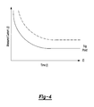
- the switch 24 is used as the current sensor (see Figure 3 ).
- the battery control unit 26 monitors the current being drawn across the switch 24.
- the current is measured using the resistance R on as a current shunt that converts the current into a voltage that can be read by the battery control unit.
- Other types of current sensors e.g., a Hall effect current sensor
- the battery control unit 26 implements a re-settable software-implemented fuse.
- the battery control unit 26 receives a signal indicative of current from the current sensor 25.
- the battery control unit 25 controls the switch 24 to interrupt current flow from the battery cells, thereby avoiding a damaging overcurrent scenario.
- the software-implemented fuse is designed to protect components in the battery pack as well as components outside of the battery pack such as an electrical device connected thereto.
- the software fuse may be designed to protect the battery cells, cell interconnects, battery straps, welds, power switches, wiring, an attached tool, etc.
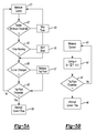
- the battery control unit 26 controls the switch as a function of current and time. If current is high, circuit components are only capable of withstanding very short durations of such current levels before overheating and/or failing. On the other hand, when current is sufficiently low, circuit components are able to operate indefinitely without overheating or failing. This relationship is defined by the squared value of current over time as shown in Figure 4 .
- the battery control unit 26 may open the switch 24 and thereby interrupt current flow from the battery.
- the trip point for the software-implemented fuse is preferably less than the trip point of fuse 28 as shown in Figure 4 . In the event of a malfunction of the software-implemented fuse, fuse 28 provides a secondary protection mechanism.
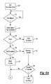
- FIG. 5A illustrates an exemplary implementation for how this function may be implemented by the battery control unit 26.
- Current sensed by the current sensor 25 is being continually reported to or measured by the battery control unit 26 as indicated at 41. For instance, the current may be measured every 100 ms.
- Q ⁇ l 2 - k dt.
- the summed current value is then compared at 44 to a predefined trip point. When the summed current value exceeds the trip point, the battery control unit initiates a protective action to protect the battery pack as indicated at 46; otherwise, monitoring continues at 41.
- Figure 5B illustrates an alternative implementation for how this function may be implemented by the battery control unit 26.
- Current sensed by the current sensor 25 is being continually reported to or measured by the battery control unit 26 as indicated at 51.
- the sensed current is first compared at 52 to a predetermined minimum current threshold value. When the sensed current does not exceed the minimum current threshold, there is no risk of an overcurrent scenario and no further evaluation is needed. If a timer was previously running, the timer is terminated as indicated at 53.
- the battery control unit will start a timer at 55. Prior to doing so, a check is performed at 54 to see if a timer has been previously started. If so, this step is bypassed.
- the battery control unit will evaluate the trip point of the software-implemented fuse.
- a timeout value is retrieved from a lookup table.
- the timeout value will correlate to the sensed current value. As discussed above, the higher the sensed current value, the shorted the timeout value.
- the timeout values are stored in a lookup table stored in a memory device associated with the battery control unit. It is readily understood that table values will depend on the particular application and may be derived accordingly.
- the timeout value is then compared to the timer value as indicated at 58.
- the timer value exceeds the timeout value, the battery control unit will open the switch 24 and thereby interrupt current flow from the battery cells.
- the timeout value serves as the trip point for the software-implemented fuse.
- another current measure is obtained. If the current changes while the timer is running 56, a new timeout value will be retrieved as indicated at 57; otherwise, processing remains as described above. It is to be understood that only the relevant steps of the methodology are discussed in relation to Figure 5 , but that other software-implemented instructions may be needed to control and manage the overall operation of the system. It is also contemplated that the fuse function described above may be implemented in hardware using digital or analog circuitry or a combination thereof.
- the software-implemented fuse may be temperature compensated so as to avoid spurious protective actions from occurring during normal operations, in which the user is drilling down or some tool application causes the user to run the tool hard for a short period of time.
- the trip point of the software-implemented fuse may be compensated for temperature variations in either the switch or the battery cells.
- the timeout value is retrieved from a lookup table based on a temperature value and the sensed current value.
- the trip point may be compensated based on the voltage level of the battery cells in a similar manner. Compensating the trip point for other battery parameters is also contemplated.
- the software-implemented fuse may function cooperatively with an over-discharge protection feature.
- current discharge from the battery pack is interrupted when an individual cell voltage or the battery stack voltage drops below a predefined voltage threshold.
- the voltage threshold for the over-discharge function is dynamically varied based on other operating conditions, such as pack temperature or instantaneous discharge current.
- the over-current and over-discharge protection features enable the battery pack to meet the varied operating conditions found in power tool applications.
- Software-implemented fuses are advantageous in that they may be re-set.
- the battery control unit may subsequently close the switch, thereby permitting current to flow from the battery.
- a secondary timer is started at 61 once the switch is initially opened by the battery control unit as shown in Figure 6 .
- the battery control unit will not close the switch until a predetermined period of time has elapsed 62 as denoted by the secondary timer.
- other fault criteria may be evaluated as further discussed below.
- the battery control module may check if any battery fault conditions exist as indicated at 63. For example, does the voltage level of the battery cells exceed some minimum threshold. If so, the software-implemented fuse may be reset; otherwise, the switch remains open and an indicia of the fault condition may be generated 65 by the battery control unit. Additional battery fault conditions may be checked and are contemplated by this disclosure.
- the battery control module may determine if the power tool has been operational 66 since the last overcurrent condition was detected. Overcurrent conditions are frequently caused by operating conditions of the tool which may change over time or otherwise resolve themselves (e.g., a bit jam condition of a drill). If the tool has not been operational, then a counter is incremented at 67. When the counter reaches some predetermined number without the tool having been operational, it may be inferred that the problem causing the overcurrent condition will persist. In this case, the software-implemented fuse is not reset and an applicable indicia of the fault condition may be generated 70 by the battery control unit. On the other hand, if the tool has been operational, then the counter may be reset at 68.
- the battery control unit may also monitor a trigger switch of the power tool at 72.
- the trigger switch of the tool When the trigger switch of the tool is an off position, the software-implemented fuse may be reset as indicated at 74. Conversely, when the trigger switch of the tool is in an on position, the battery control unit will not close the switch, but rather generate an indicia of a fault condition. This prevents the power tool from starting up unexpectedly. It is envisioned that other criteria associated with the power tool may monitored by the battery control unit prior to resetting the software-implemented fuse. Likewise, it is to be understood that only the relevant steps of the methodology are discussed in relation to Figure 6 , but that other software-implemented instructions may be needed to control and manage the overall operation of the system.
Abstract
Description
- The present disclosure relates to a battery pack and, more particularly, to a software-implemented overcurrent protection mechanism embedded in a battery pack.
- Over the past few years, lithium-ion (Li-ion) batteries have begun replacing nickel-cadmium (NiCd), nickel-metal-hydride (NiMH), and lead-acid batteries in low-voltage, portable electronic devices such as notebook-type personal computers. As compared to NiCd and NiMH batteries, Li-ion batteries are lighter but have a larger capacity per unit volume. For this reason, the Li-ion batteries are suitable to low-voltage devices that are preferably light and which are required to endure continuous use for a long time.
- Unlike a NiCd battery pack and a NiMH battery pack, Li-ion batteries deteriorate rapidly in an over-discharged state. Thus, a Li-ion battery pack may include functionality to protect against fault conditions inside and outside the Li-ion battery pack. This prevents cells in the Li-ion battery pack from deteriorating and shortening useful life of the pack. For instance, if a fault condition such as short-circuiting occurs inside or outside the Li-ion battery pack, a fuse may be provided to cut off an over-discharging current or an overcharging current, if the discharging current or charging current becomes larger than a given current level. However, a mechanical fuse needs to be replaced before the battery pack can be used again.
- Therefore, it is desirable to provide a software-implemented fuse within in a battery pack. A software-implement protection mechanism enables the fuse to be tripped under different operating conditions. Moreover, a software-implemented fuse may be reset after being tripped without intervention from a user. The statements in this section merely provide background information related to the present disclosure and may not constitute prior art
- An overcurrent protection mechanism is provided for a battery pack that may removably attaches to a power tool. The mechanism includes: one or more battery cells disposed in a battery pack; a current sensor configured to sense current supplied by the battery; a switch in a circuit path with the battery cells; and a battery control unit implemented as software instructions in a controller embedded in a battery pack. The battery control unit is configured to receive a signal indicative of current from the current sensor and control the switch to interrupt current flow from the battery cells as a function of current and time.
- Further areas of applicability will become apparent from the description provided herein. It should be understood that the description and specific examples are intended for purposes of illustration only and are not intended to limit the scope of the present disclosure.
-
Figure 1 is a diagram of an exemplary system of power tools; -
Figure 2 is a schematic of an exemplary circuit configuration for an overcurrent protection mechanism integrated into a battery pack; -
Figure 3 is a schematic of an alternative circuit configuration for an overcurrent protection mechanism integrated into a battery pack; -
Figure 4 is a graph illustrating an exemplary trip point for a software-implemented fuse; -
Figure 5A is a flowchart showing an exemplary implementation for the fuse; -
Figure 5B is a flowchart showing another exemplary implementation for the fuse; and -
Figures 6A and6B are a flowchart showing exemplary criteria which may be checked before a software-implemented fuse is reset. - The drawings described herein are for illustration purposes only and are not intended to limit the scope of the present disclosure in any way.
- The present disclosure can relate to a system of power tools of the type that is generally indicated by
reference numeral 10 inFigure 1 . The system ofpower tools 10 can include, for example, one ormore power tools 12, abattery pack 16 and abattery pack charger 18. Each of thepower tools 12 can be any type of power tool, including without limitation drills, drill/drivers, hammer drill/drivers, rotary hammers, screwdrivers, impact drivers, circular saws, jig saws, reciprocating saws, band saws, cut-off tools, cut-out tools, shears, sanders, vacuums, lights, routers, adhesive dispensers, concrete vibrators, lasers, staplers and nailers. In the particular example provided, the system ofpower tools 10 includes afirst power tool 12a and asecond power tool 12b. For example, thefirst power tool 12a can be a drill/driver similar to that which is described inU.S. Patent No. 6,431,289 , while thesecond power tool 12b can be a circular saw similar to that which is described inU.S. Patent No. 6,996,909 . Thebattery pack 16 can be selectively removably coupled to the first andsecond power tools battery pack 16 can be configured in a manner that is similar to that which is described inU.S. Patent Application Publication No. 2006/0096771 . Thebattery pack 16 can also be selectively electrically coupled to thebattery pack charger 18 to charge thebattery pack 16. It is noteworthy that the broader aspects of this disclosure are applicable to other types of battery powered devices. -
Figure 2 illustrates an exemplary circuit configuration for an overcurrent protection mechanism 20 integrated into abattery pack 16. The overcurrent protection mechanism 20 is comprised generally ofbattery cells 22, aswitch 24 for controlling discharge of the battery cells, acurrent sensor 25, and abattery control unit 26. The overcurrent protection mechanism 20 may also include afuse 28 placed in series with the battery cells. Each of these components is preferably integrated into thebattery pack 16. However, it is envisioned that one or more of these components, excluding the battery cells, may be located in a battery charger, a power tool or some other external device operably coupled to the battery pack. - The battery pack may include a plurality of
battery cells 22 connected in series, and/or a plurality of serially-connected strings of cells, in which the strings are in parallel with one another. For purposes of describing the exemplary embodiments, the battery pack may be composed of cells having lithium-ion cell chemistry. In the context of cordless power tools, the nominal voltage rating of the battery pack is typically at least 18 volts. However, other voltage ratings are contemplated for different applications. In addition, the battery pack may be composed of cells of another lithium-based chemistry, such as lithium metal or lithium polymer, or other chemistry such as nickel cadmium (NiCd), nickel metal hydride (NiMH) and lead-acid, for example, in terms of the chemistry makeup of individual cells, electrodes and electrolyte of the pack. Although not limited thereto, thebattery pack 16 is preferably rechargeable. - A
battery control unit 26 embedded within thebattery pack 16 is responsible for protecting the battery cells and monitoring any fault conditions which may develop. In an exemplary embodiment, thebattery control unit 16 is implemented in software on a digital microcontroller. However, thebattery control unit 26 may be embodied in hardware or software as a digital microcontroller, a microprocessor or an analog circuit, a digital signal processor or by one or more digital ICs such as application specific integrated circuits (ASICs), for example. - Discharge current from the battery cells and charge current to the battery cells can be clamped or discontinued through the use of a
switch 24. Theswitch 24 may be placed in series with the battery cells on the low voltage side of the battery cells. Theswitch 24 can then be controlled by the battery control unit to interrupt current flow to/from the battery cells. In an exemplary embodiment, theswitch 24 is a transistor (e.g., a MOSFET). Other types of switches are also contemplated by this disclosure. - The
current sensor 25 is configured to sense the current being supplied by the battery and provide a signal indicative of the sensed current to thebattery control unit 26. In an exemplary embodiment, thecurrent sensor 25 may be implemented using a current shunt disposed in series with thebattery cells 22. The current shunt is preferably positioned on the low voltage side of the battery cells. In an alternative embodiment, theswitch 24 is used as the current sensor (seeFigure 3 ). In other words, thebattery control unit 26 monitors the current being drawn across theswitch 24. In the case of the transistor, the current is measured using the resistance Ron as a current shunt that converts the current into a voltage that can be read by the battery control unit. Other types of current sensors (e.g., a Hall effect current sensor) are also within the scope of this disclosure. - The
battery control unit 26 implements a re-settable software-implemented fuse. In operation, thebattery control unit 26 receives a signal indicative of current from thecurrent sensor 25. When the current value exceeds some threshold, thebattery control unit 25 controls theswitch 24 to interrupt current flow from the battery cells, thereby avoiding a damaging overcurrent scenario. In this way, the software-implemented fuse is designed to protect components in the battery pack as well as components outside of the battery pack such as an electrical device connected thereto. For example, the software fuse may be designed to protect the battery cells, cell interconnects, battery straps, welds, power switches, wiring, an attached tool, etc. - In an exemplary embodiment, the
battery control unit 26 controls the switch as a function of current and time. If current is high, circuit components are only capable of withstanding very short durations of such current levels before overheating and/or failing. On the other hand, when current is sufficiently low, circuit components are able to operate indefinitely without overheating or failing. This relationship is defined by the squared value of current over time as shown inFigure 4 . Thebattery control unit 26 may implement this relationship as the trip point for the software-implemented fuse. For instance, the trip point may be defined as: F(I, t) = ∫ l2 dt, where I is the sensed current value from thecurrent sensor 25. When the trip point is exceeded, thebattery control unit 26 initiates a protective action to protect the battery pack. For instance, thebattery control unit 26 may open theswitch 24 and thereby interrupt current flow from the battery. The trip point for the software-implemented fuse is preferably less than the trip point offuse 28 as shown inFigure 4 . In the event of a malfunction of the software-implemented fuse, fuse 28 provides a secondary protection mechanism. -
Figure 5A illustrates an exemplary implementation for how this function may be implemented by thebattery control unit 26. Current sensed by thecurrent sensor 25 is being continually reported to or measured by thebattery control unit 26 as indicated at 41. For instance, the current may be measured every 100 ms. Current value over a period of time may be computed at 42 using the following function: Q = Σ l2 - k dt. Thus, the measured current is squared and summed with previous current measurements. A constant k is used to select a minimum value the summation will be incremented. The summed current value is then compared at 44 to a predefined trip point. When the summed current value exceeds the trip point, the battery control unit initiates a protective action to protect the battery pack as indicated at 46; otherwise, monitoring continues at 41. -
Figure 5B illustrates an alternative implementation for how this function may be implemented by thebattery control unit 26. Current sensed by thecurrent sensor 25 is being continually reported to or measured by thebattery control unit 26 as indicated at 51. The sensed current is first compared at 52 to a predetermined minimum current threshold value. When the sensed current does not exceed the minimum current threshold, there is no risk of an overcurrent scenario and no further evaluation is needed. If a timer was previously running, the timer is terminated as indicated at 53. - When the sensed current exceeds the minimum current threshold, there is a risk of an overcurrent scenario. In this case, the battery control unit will start a timer at 55. Prior to doing so, a check is performed at 54 to see if a timer has been previously started. If so, this step is bypassed.
- Next, the battery control unit will evaluate the trip point of the software-implemented fuse. A timeout value is retrieved from a lookup table. The timeout value will correlate to the sensed current value. As discussed above, the higher the sensed current value, the shorted the timeout value. The timeout values are stored in a lookup table stored in a memory device associated with the battery control unit. It is readily understood that table values will depend on the particular application and may be derived accordingly.
- The timeout value is then compared to the timer value as indicated at 58. When the timer value exceeds the timeout value, the battery control unit will open the
switch 24 and thereby interrupt current flow from the battery cells. In other words, the timeout value serves as the trip point for the software-implemented fuse. When the timer value does not exceed the timeout value, another current measure is obtained. If the current changes while the timer is running 56, a new timeout value will be retrieved as indicated at 57; otherwise, processing remains as described above. It is to be understood that only the relevant steps of the methodology are discussed in relation toFigure 5 , but that other software-implemented instructions may be needed to control and manage the overall operation of the system. It is also contemplated that the fuse function described above may be implemented in hardware using digital or analog circuitry or a combination thereof. - The software-implemented fuse may be temperature compensated so as to avoid spurious protective actions from occurring during normal operations, in which the user is drilling down or some tool application causes the user to run the tool hard for a short period of time. In exemplary embodiments, the trip point of the software-implemented fuse may be compensated for temperature variations in either the switch or the battery cells. In this case, the timeout value is retrieved from a lookup table based on a temperature value and the sensed current value. Alternatively, the trip point may be compensated based on the voltage level of the battery cells in a similar manner. Compensating the trip point for other battery parameters is also contemplated.
- In addition, the software-implemented fuse may function cooperatively with an over-discharge protection feature. In an exemplary implementation, current discharge from the battery pack is interrupted when an individual cell voltage or the battery stack voltage drops below a predefined voltage threshold. In a more robust implementation, the voltage threshold for the over-discharge function is dynamically varied based on other operating conditions, such as pack temperature or instantaneous discharge current. The over-current and over-discharge protection features enable the battery pack to meet the varied operating conditions found in power tool applications.
- Software-implemented fuses are advantageous in that they may be re-set. In other words, the battery control unit may subsequently close the switch, thereby permitting current to flow from the battery. Prior to closing the switch, it is prudent to allow any heat generated by the overcurrent situation to dissipate. Thus, a secondary timer is started at 61 once the switch is initially opened by the battery control unit as shown in
Figure 6 . The battery control unit will not close the switch until a predetermined period of time has elapsed 62 as denoted by the secondary timer. Before the switch is closed, other fault criteria may be evaluated as further discussed below. - With continued reference to
Figures 6A and6B , a few exemplary criteria may be checked when the battery pack is operably coupled to a power tool. First, the battery control module may check if any battery fault conditions exist as indicated at 63. For example, does the voltage level of the battery cells exceed some minimum threshold. If so, the software-implemented fuse may be reset; otherwise, the switch remains open and an indicia of the fault condition may be generated 65 by the battery control unit. Additional battery fault conditions may be checked and are contemplated by this disclosure. - Next, the battery control module may determine if the power tool has been operational 66 since the last overcurrent condition was detected. Overcurrent conditions are frequently caused by operating conditions of the tool which may change over time or otherwise resolve themselves (e.g., a bit jam condition of a drill). If the tool has not been operational, then a counter is incremented at 67. When the counter reaches some predetermined number without the tool having been operational, it may be inferred that the problem causing the overcurrent condition will persist. In this case, the software-implemented fuse is not reset and an applicable indicia of the fault condition may be generated 70 by the battery control unit. On the other hand, if the tool has been operational, then the counter may be reset at 68.
- The battery control unit may also monitor a trigger switch of the power tool at 72. When the trigger switch of the tool is an off position, the software-implemented fuse may be reset as indicated at 74. Conversely, when the trigger switch of the tool is in an on position, the battery control unit will not close the switch, but rather generate an indicia of a fault condition. This prevents the power tool from starting up unexpectedly. It is envisioned that other criteria associated with the power tool may monitored by the battery control unit prior to resetting the software-implemented fuse. Likewise, it is to be understood that only the relevant steps of the methodology are discussed in relation to
Figure 6 , but that other software-implemented instructions may be needed to control and manage the overall operation of the system. - The above description is merely exemplary in nature and is not intended to limit the present disclosure, application, or uses
Claims (13)
- A battery pack, comprising:one or more battery cells;a switch in a circuit path with the battery cells;a current sensor configured to sense current supplied by the battery; anda battery control unit adapted to receive a signal indicative of current from the current sensor and operable to control the switch to interrupt current flow from the battery cells as a function of current and time.
- A battery pack, comprising:one or more battery cells;a switch in series with the battery cells; anda battery control unit embedded as software instructions in a controller and configured to measure current across the switch, the battery control unit operable to control the switch to interrupt current flow from the battery cells as a function of current and time.
- The battery pack of claim 1 or 2 wherein the switch is defined as a transistor.
- The battery pack of claim 1 wherein the current sensor is a current shunt disposed in the circuit path with the battery cells.
- The battery pack of claim 1 or 2 wherein the battery control unit is operable to open the switch when the current exceeds a threshold.
- The battery pack of claim 1 wherein the battery control unit is operable to open the switch as a function of time and the current sensed by the current sensor.
- The battery pack of claim 1 wherein the battery control unit is operable to open the switch as a function of time, temperature and current sensed by the current sensor.
- The battery pack of claim 1 wherein the battery control unit is operable to open the switch as a function of time, voltage level of the battery cells and current sensed by the current sensor.
- The battery pack of claim 1 or 2 wherein the battery control unit is operable to close the switch after a period of time has passed.
- The battery pack of claim 1 or 2 is operably coupled to a power tool, wherein the battery control unit is operable to close the switch only when a trigger switch of a power tool is in an off position.
- The battery pack of claim 1 or 2 wherein the battery control unit is operable to close the switch when a battery fault condition is deemed safe.
- The battery pack of claim 1 or 2 wherein the battery control unit is operable to close the switch when a voltage level of the battery cells exceeds a threshold.
- The battery pack of claim 2 wherein the battery control unit is operable to integrate a square value of the current over time and open the switch when the integrated value exceeds a threshold.
Applications Claiming Priority (1)
| Application Number | Priority Date | Filing Date | Title |
|---|---|---|---|
| US93369507P | 2007-06-07 | 2007-06-07 |
Publications (3)
| Publication Number | Publication Date |
|---|---|
| EP2017917A2 true EP2017917A2 (en) | 2009-01-21 |
| EP2017917A3 EP2017917A3 (en) | 2011-10-26 |
| EP2017917B1 EP2017917B1 (en) | 2013-04-10 |
Family
ID=39884377
Family Applications (1)
| Application Number | Title | Priority Date | Filing Date |
|---|---|---|---|
| EP08157591.2A Expired - Fee Related EP2017917B1 (en) | 2007-06-07 | 2008-06-04 | Software-implemented overcurrent protection embedded in a battery pack |
Country Status (3)
| Country | Link |
|---|---|
| US (1) | US20080304199A1 (en) |
| EP (1) | EP2017917B1 (en) |
| CN (1) | CN201383674Y (en) |
Families Citing this family (17)
| Publication number | Priority date | Publication date | Assignee | Title |
|---|---|---|---|---|
| US20120055687A1 (en) * | 2009-04-24 | 2012-03-08 | Husqvarna Ab | Battery operated portable tools |
| CN201565924U (en) * | 2009-07-17 | 2010-09-01 | 南京德朔实业有限公司 | DC electric tool |
| US8179276B2 (en) * | 2009-09-29 | 2012-05-15 | Tyco Healthcare Group Lp | Battery assembly with alarm |
| US9337763B2 (en) | 2010-10-27 | 2016-05-10 | Hitachi Koki Co., Ltd. | Power tool system and power supply device |
| JP5602170B2 (en) * | 2012-03-03 | 2014-10-08 | レノボ・シンガポール・プライベート・リミテッド | Method and electronic apparatus for controlling operation of processor |
| DE102012205344B4 (en) * | 2012-04-02 | 2023-10-19 | Robert Bosch Gmbh | Method for operating a power tool |
| JP6283613B2 (en) * | 2012-09-25 | 2018-02-21 | 日本碍子株式会社 | Module battery and method for manufacturing module battery |
| US9608430B2 (en) * | 2013-04-11 | 2017-03-28 | International Business Machines Corporation | Battery circuit fault protection in uninterruptable power sources |
| DE102013213267A1 (en) * | 2013-07-05 | 2015-01-08 | Robert Bosch Gmbh | Method for battery management and battery management system |
| US10291013B2 (en) * | 2013-11-20 | 2019-05-14 | Nokia Technologies Oy | Adaptive battery protection |
| JP6472076B2 (en) | 2015-03-06 | 2019-02-20 | Fdk株式会社 | Load current control device |
| CN106711957B (en) * | 2015-07-27 | 2019-02-19 | 长城汽车股份有限公司 | A kind of protection circuit, vehicle power supply and the automobile of lithium battery monomer |
| CN108139445B (en) * | 2015-10-05 | 2023-07-14 | 株式会社村田制作所 | Residual amount measuring device, battery pack, electric tool, electric aircraft, electric vehicle, and power supply device |
| CN106249093A (en) * | 2016-07-22 | 2016-12-21 | 上海新时达电气股份有限公司 | Automatically differentiate and detect the devices and methods therefor of pre-buried sensor in electrical equipment |
| US10978889B1 (en) * | 2017-06-14 | 2021-04-13 | Hadal, Inc. | System and methods for multi-level battery protection |
| CN107918046B (en) | 2017-10-23 | 2021-01-22 | 宁德时代新能源科技股份有限公司 | Current detection device and battery management system |
| US11186198B2 (en) * | 2019-05-31 | 2021-11-30 | Ford Global Technologies, Llc | Methods and systems for vehicle battery cell failure detection and overcharge protection |
Citations (3)
| Publication number | Priority date | Publication date | Assignee | Title |
|---|---|---|---|---|
| US6431289B1 (en) | 2001-01-23 | 2002-08-13 | Black & Decker Inc. | Multi-speed power tool transmission |
| US6996909B1 (en) | 1998-08-13 | 2006-02-14 | Black & Decker Inc. | Battery powered circular saw |
| US20060096771A1 (en) | 2004-11-08 | 2006-05-11 | Brotto Daniele C | Ergonomically efficient cordless power tool |
Family Cites Families (16)
| Publication number | Priority date | Publication date | Assignee | Title |
|---|---|---|---|---|
| DE2340123A1 (en) * | 1973-08-08 | 1975-02-20 | Schwarzer Gmbh Fritz | OVERCURRENT PROTECTION CIRCUIT |
| US4809125A (en) * | 1987-02-20 | 1989-02-28 | Westinghouse Electric Corp. | Circuit interrupter apparatus with a style saving rating plug |
| US5136457A (en) * | 1989-08-31 | 1992-08-04 | Square D Company | Processor controlled circuit breaker trip system having an intelligent rating plug |
| US5331501A (en) * | 1992-09-30 | 1994-07-19 | Westinghouse Electric Corp. | Electrical switching apparatus with digital trip unit and memory reset |
| US5269458A (en) * | 1993-01-14 | 1993-12-14 | David Sol | Furnace monitoring and thermostat cycling system for recreational vehicles and marine vessels |
| SE516507C2 (en) * | 1996-12-23 | 2002-01-22 | Ericsson Telefon Ab L M | Rechargeable battery with built-in safety circuit for a portable electrical appliance |
| US6046575A (en) * | 1998-03-31 | 2000-04-04 | Motorola, Inc. | Fail safe circuit and battery pack using same |
| JP3670522B2 (en) * | 1999-07-30 | 2005-07-13 | 富士通株式会社 | Battery pack |
| JP3431867B2 (en) * | 1999-09-21 | 2003-07-28 | 松下電器産業株式会社 | Battery power supply device and electric equipment using the same |
| CA2295286A1 (en) * | 2000-01-10 | 2001-07-10 | Delta Electronics Inc. | A simplified leakage current circuit breaking and overcurrent protection device |
| US7157882B2 (en) * | 2002-11-22 | 2007-01-02 | Milwaukee Electric Tool Corporation | Method and system for battery protection employing a selectively-actuated switch |
| US6903533B1 (en) * | 2003-12-16 | 2005-06-07 | Motorola, Inc. | Power fault battery protection circuit |
| FR2867319B1 (en) * | 2004-03-08 | 2006-05-05 | Renault Sas | BATTERY DISCHARGE DEVICE BY CONTINUOUS CONTROL OF MOS TRANSISTORS |
| US20050248320A1 (en) * | 2004-05-04 | 2005-11-10 | Denning Bruce S | Switch reduction in a cordless power tool |
| KR100844806B1 (en) * | 2005-03-31 | 2008-07-07 | 주식회사 엘지화학 | Apparatus and method for measuring the amount of the current in battery cells using a plurality of sensing resistors |
| US7342762B2 (en) * | 2005-11-10 | 2008-03-11 | Littelfuse, Inc. | Resettable circuit protection apparatus |
-
2008
- 2008-06-04 EP EP08157591.2A patent/EP2017917B1/en not_active Expired - Fee Related
- 2008-06-06 US US12/157,146 patent/US20080304199A1/en not_active Abandoned
- 2008-06-10 CN CN200820137051U patent/CN201383674Y/en not_active Expired - Fee Related
Patent Citations (3)
| Publication number | Priority date | Publication date | Assignee | Title |
|---|---|---|---|---|
| US6996909B1 (en) | 1998-08-13 | 2006-02-14 | Black & Decker Inc. | Battery powered circular saw |
| US6431289B1 (en) | 2001-01-23 | 2002-08-13 | Black & Decker Inc. | Multi-speed power tool transmission |
| US20060096771A1 (en) | 2004-11-08 | 2006-05-11 | Brotto Daniele C | Ergonomically efficient cordless power tool |
Also Published As
| Publication number | Publication date |
|---|---|
| EP2017917A3 (en) | 2011-10-26 |
| CN201383674Y (en) | 2010-01-13 |
| US20080304199A1 (en) | 2008-12-11 |
| EP2017917B1 (en) | 2013-04-10 |
Similar Documents
| Publication | Publication Date | Title |
|---|---|---|
| EP2017917B1 (en) | Software-implemented overcurrent protection embedded in a battery pack | |
| EP2015421B1 (en) | Reset mechanism for a battery pack | |
| RU2374735C2 (en) | Power-driven tool with battery supply, which has protection circuit against excess currents and battery power supply for this tool | |
| JP4579068B2 (en) | Battery pack | |
| US8154248B2 (en) | Signal for pre-charge selection in lithium charging and discharge control/pre-charge function | |
| US9859548B2 (en) | Shared control of thermistor and dual purpose thermistor line | |
| EP1780867B1 (en) | Battery pack for cordless power tools | |
| US8358108B2 (en) | System and method for re-initiating charge cycle for battery pack left in a charger | |
| JP3431867B2 (en) | Battery power supply device and electric equipment using the same | |
| JP4857585B2 (en) | Cordless power tool | |
| EP2051347A2 (en) | Method for balancing cells in a battery pack | |
| EP2003760A2 (en) | Temperature and polarization voltage compensation system | |
| US8692509B2 (en) | Charge control scheme for use in power tools | |
| US7973511B2 (en) | Method for distinguishing batteries having different chemistries | |
| JP4867734B2 (en) | Lithium battery pack and combination of battery pack and power tool |
Legal Events
| Date | Code | Title | Description |
|---|---|---|---|
| PUAI | Public reference made under article 153(3) epc to a published international application that has entered the european phase |
Free format text: ORIGINAL CODE: 0009012 |
|
| PUAI | Public reference made under article 153(3) epc to a published international application that has entered the european phase |
Free format text: ORIGINAL CODE: 0009012 |
|
| AK | Designated contracting states |
Kind code of ref document: A2 Designated state(s): AT BE BG CH CY CZ DE DK EE ES FI FR GB GR HR HU IE IS IT LI LT LU LV MC MT NL NO PL PT RO SE SI SK TR |
|
| AX | Request for extension of the european patent |
Extension state: AL BA MK RS |
|
| PUAL | Search report despatched |
Free format text: ORIGINAL CODE: 0009013 |
|
| AK | Designated contracting states |
Kind code of ref document: A3 Designated state(s): AT BE BG CH CY CZ DE DK EE ES FI FR GB GR HR HU IE IS IT LI LT LU LV MC MT NL NO PL PT RO SE SI SK TR |
|
| AX | Request for extension of the european patent |
Extension state: AL BA MK RS |
|
| AKY | No designation fees paid | ||
| REG | Reference to a national code |
Ref country code: DE Ref legal event code: R108 |
|
| 17P | Request for examination filed |
Effective date: 20120502 |
|
| RBV | Designated contracting states (corrected) |
Designated state(s): DE GB |
|
| REG | Reference to a national code |
Ref country code: DE Ref legal event code: R108 Ref document number: 602008023624 Country of ref document: DE Effective date: 20120704 |
|
| RIC1 | Information provided on ipc code assigned before grant |
Ipc: H01M 10/44 20060101ALI20120821BHEP Ipc: H01M 10/0525 20100101ALI20120821BHEP Ipc: H01M 10/42 20060101AFI20120821BHEP |
|
| GRAP | Despatch of communication of intention to grant a patent |
Free format text: ORIGINAL CODE: EPIDOSNIGR1 |
|
| GRAP | Despatch of communication of intention to grant a patent |
Free format text: ORIGINAL CODE: EPIDOSNIGR1 |
|
| GRAS | Grant fee paid |
Free format text: ORIGINAL CODE: EPIDOSNIGR3 |
|
| GRAA | (expected) grant |
Free format text: ORIGINAL CODE: 0009210 |
|
| AK | Designated contracting states |
Kind code of ref document: B1 Designated state(s): DE GB |
|
| REG | Reference to a national code |
Ref country code: GB Ref legal event code: FG4D |
|
| REG | Reference to a national code |
Ref country code: DE Ref legal event code: R096 Ref document number: 602008023624 Country of ref document: DE Effective date: 20130606 |
|
| PLBE | No opposition filed within time limit |
Free format text: ORIGINAL CODE: 0009261 |
|
| STAA | Information on the status of an ep patent application or granted ep patent |
Free format text: STATUS: NO OPPOSITION FILED WITHIN TIME LIMIT |
|
| 26N | No opposition filed |
Effective date: 20140113 |
|
| REG | Reference to a national code |
Ref country code: DE Ref legal event code: R097 Ref document number: 602008023624 Country of ref document: DE Effective date: 20140113 |
|
| PGFP | Annual fee paid to national office [announced via postgrant information from national office to epo] |
Ref country code: GB Payment date: 20220414 Year of fee payment: 15 Ref country code: DE Payment date: 20220414 Year of fee payment: 15 |
|
| REG | Reference to a national code |
Ref country code: DE Ref legal event code: R119 Ref document number: 602008023624 Country of ref document: DE |
|
| GBPC | Gb: european patent ceased through non-payment of renewal fee |
Effective date: 20230604 |