EP2026247A2 - Automatic headlamp control system - Google Patents
Automatic headlamp control system Download PDFInfo
- Publication number
- EP2026247A2 EP2026247A2 EP08014520A EP08014520A EP2026247A2 EP 2026247 A2 EP2026247 A2 EP 2026247A2 EP 08014520 A EP08014520 A EP 08014520A EP 08014520 A EP08014520 A EP 08014520A EP 2026247 A2 EP2026247 A2 EP 2026247A2
- Authority
- EP
- European Patent Office
- Prior art keywords
- vehicle
- control
- imaging system
- image data
- data set
- Prior art date
- Legal status (The legal status is an assumption and is not a legal conclusion. Google has not performed a legal analysis and makes no representation as to the accuracy of the status listed.)
- Granted
Links
- 238000003384 imaging method Methods 0.000 claims abstract description 60
- 238000000034 method Methods 0.000 claims abstract description 39
- 230000008569 process Effects 0.000 claims abstract description 34
- 230000004044 response Effects 0.000 claims abstract description 23
- 230000008859 change Effects 0.000 claims abstract description 7
- 238000012545 processing Methods 0.000 claims description 33
- 238000001514 detection method Methods 0.000 claims description 19
- 238000013459 approach Methods 0.000 claims description 5
- 238000004364 calculation method Methods 0.000 claims description 3
- 230000003044 adaptive effect Effects 0.000 description 7
- 238000004519 manufacturing process Methods 0.000 description 7
- 238000004891 communication Methods 0.000 description 5
- 238000005286 illumination Methods 0.000 description 5
- 239000003550 marker Substances 0.000 description 4
- 238000003491 array Methods 0.000 description 3
- 239000003086 colorant Substances 0.000 description 3
- 238000012937 correction Methods 0.000 description 3
- 230000007423 decrease Effects 0.000 description 3
- 238000009434 installation Methods 0.000 description 3
- 230000003287 optical effect Effects 0.000 description 3
- 230000009286 beneficial effect Effects 0.000 description 2
- 230000008901 benefit Effects 0.000 description 2
- 230000008034 disappearance Effects 0.000 description 2
- 230000004438 eyesight Effects 0.000 description 2
- 238000012544 monitoring process Methods 0.000 description 2
- 230000003595 spectral effect Effects 0.000 description 2
- 239000000758 substrate Substances 0.000 description 2
- 238000012935 Averaging Methods 0.000 description 1
- 241000282412 Homo Species 0.000 description 1
- 230000004913 activation Effects 0.000 description 1
- 230000006978 adaptation Effects 0.000 description 1
- 230000002411 adverse Effects 0.000 description 1
- 230000009118 appropriate response Effects 0.000 description 1
- 230000033228 biological regulation Effects 0.000 description 1
- 238000004140 cleaning Methods 0.000 description 1
- 238000013500 data storage Methods 0.000 description 1
- 238000013461 design Methods 0.000 description 1
- 238000010586 diagram Methods 0.000 description 1
- 230000007613 environmental effect Effects 0.000 description 1
- 230000004313 glare Effects 0.000 description 1
- 229910052736 halogen Inorganic materials 0.000 description 1
- 150000002367 halogens Chemical class 0.000 description 1
- 238000010438 heat treatment Methods 0.000 description 1
- 238000012986 modification Methods 0.000 description 1
- 230000004048 modification Effects 0.000 description 1
- 238000003032 molecular docking Methods 0.000 description 1
- 230000008447 perception Effects 0.000 description 1
- 238000012552 review Methods 0.000 description 1
- 239000004065 semiconductor Substances 0.000 description 1
- 230000035945 sensitivity Effects 0.000 description 1
- 238000001228 spectrum Methods 0.000 description 1
- 230000002123 temporal effect Effects 0.000 description 1
Images


Classifications
-
- G—PHYSICS
- G06—COMPUTING; CALCULATING OR COUNTING
- G06T—IMAGE DATA PROCESSING OR GENERATION, IN GENERAL
- G06T7/00—Image analysis
- G06T7/80—Analysis of captured images to determine intrinsic or extrinsic camera parameters, i.e. camera calibration
-
- B—PERFORMING OPERATIONS; TRANSPORTING
- B60—VEHICLES IN GENERAL
- B60Q—ARRANGEMENT OF SIGNALLING OR LIGHTING DEVICES, THE MOUNTING OR SUPPORTING THEREOF OR CIRCUITS THEREFOR, FOR VEHICLES IN GENERAL
- B60Q1/00—Arrangement of optical signalling or lighting devices, the mounting or supporting thereof or circuits therefor
- B60Q1/02—Arrangement of optical signalling or lighting devices, the mounting or supporting thereof or circuits therefor the devices being primarily intended to illuminate the way ahead or to illuminate other areas of way or environments
- B60Q1/04—Arrangement of optical signalling or lighting devices, the mounting or supporting thereof or circuits therefor the devices being primarily intended to illuminate the way ahead or to illuminate other areas of way or environments the devices being headlights
- B60Q1/06—Arrangement of optical signalling or lighting devices, the mounting or supporting thereof or circuits therefor the devices being primarily intended to illuminate the way ahead or to illuminate other areas of way or environments the devices being headlights adjustable, e.g. remotely-controlled from inside vehicle
- B60Q1/08—Arrangement of optical signalling or lighting devices, the mounting or supporting thereof or circuits therefor the devices being primarily intended to illuminate the way ahead or to illuminate other areas of way or environments the devices being headlights adjustable, e.g. remotely-controlled from inside vehicle automatically
- B60Q1/085—Arrangement of optical signalling or lighting devices, the mounting or supporting thereof or circuits therefor the devices being primarily intended to illuminate the way ahead or to illuminate other areas of way or environments the devices being headlights adjustable, e.g. remotely-controlled from inside vehicle automatically due to special conditions, e.g. adverse weather, type of road, badly illuminated road signs or potential dangers
-
- B—PERFORMING OPERATIONS; TRANSPORTING
- B60—VEHICLES IN GENERAL
- B60Q—ARRANGEMENT OF SIGNALLING OR LIGHTING DEVICES, THE MOUNTING OR SUPPORTING THEREOF OR CIRCUITS THEREFOR, FOR VEHICLES IN GENERAL
- B60Q1/00—Arrangement of optical signalling or lighting devices, the mounting or supporting thereof or circuits therefor
- B60Q1/02—Arrangement of optical signalling or lighting devices, the mounting or supporting thereof or circuits therefor the devices being primarily intended to illuminate the way ahead or to illuminate other areas of way or environments
- B60Q1/04—Arrangement of optical signalling or lighting devices, the mounting or supporting thereof or circuits therefor the devices being primarily intended to illuminate the way ahead or to illuminate other areas of way or environments the devices being headlights
- B60Q1/14—Arrangement of optical signalling or lighting devices, the mounting or supporting thereof or circuits therefor the devices being primarily intended to illuminate the way ahead or to illuminate other areas of way or environments the devices being headlights having dimming means
- B60Q1/1415—Dimming circuits
- B60Q1/1423—Automatic dimming circuits, i.e. switching between high beam and low beam due to change of ambient light or light level in road traffic
-
- B—PERFORMING OPERATIONS; TRANSPORTING
- B60—VEHICLES IN GENERAL
- B60R—VEHICLES, VEHICLE FITTINGS, OR VEHICLE PARTS, NOT OTHERWISE PROVIDED FOR
- B60R1/00—Optical viewing arrangements; Real-time viewing arrangements for drivers or passengers using optical image capturing systems, e.g. cameras or video systems specially adapted for use in or on vehicles
- B60R1/20—Real-time viewing arrangements for drivers or passengers using optical image capturing systems, e.g. cameras or video systems specially adapted for use in or on vehicles
- B60R1/22—Real-time viewing arrangements for drivers or passengers using optical image capturing systems, e.g. cameras or video systems specially adapted for use in or on vehicles for viewing an area outside the vehicle, e.g. the exterior of the vehicle
- B60R1/23—Real-time viewing arrangements for drivers or passengers using optical image capturing systems, e.g. cameras or video systems specially adapted for use in or on vehicles for viewing an area outside the vehicle, e.g. the exterior of the vehicle with a predetermined field of view
- B60R1/24—Real-time viewing arrangements for drivers or passengers using optical image capturing systems, e.g. cameras or video systems specially adapted for use in or on vehicles for viewing an area outside the vehicle, e.g. the exterior of the vehicle with a predetermined field of view in front of the vehicle
-
- B—PERFORMING OPERATIONS; TRANSPORTING
- B60—VEHICLES IN GENERAL
- B60R—VEHICLES, VEHICLE FITTINGS, OR VEHICLE PARTS, NOT OTHERWISE PROVIDED FOR
- B60R1/00—Optical viewing arrangements; Real-time viewing arrangements for drivers or passengers using optical image capturing systems, e.g. cameras or video systems specially adapted for use in or on vehicles
- B60R1/20—Real-time viewing arrangements for drivers or passengers using optical image capturing systems, e.g. cameras or video systems specially adapted for use in or on vehicles
- B60R1/22—Real-time viewing arrangements for drivers or passengers using optical image capturing systems, e.g. cameras or video systems specially adapted for use in or on vehicles for viewing an area outside the vehicle, e.g. the exterior of the vehicle
- B60R1/28—Real-time viewing arrangements for drivers or passengers using optical image capturing systems, e.g. cameras or video systems specially adapted for use in or on vehicles for viewing an area outside the vehicle, e.g. the exterior of the vehicle with an adjustable field of view
-
- G—PHYSICS
- G06—COMPUTING; CALCULATING OR COUNTING
- G06V—IMAGE OR VIDEO RECOGNITION OR UNDERSTANDING
- G06V20/00—Scenes; Scene-specific elements
- G06V20/50—Context or environment of the image
- G06V20/56—Context or environment of the image exterior to a vehicle by using sensors mounted on the vehicle
- G06V20/58—Recognition of moving objects or obstacles, e.g. vehicles or pedestrians; Recognition of traffic objects, e.g. traffic signs, traffic lights or roads
- G06V20/584—Recognition of moving objects or obstacles, e.g. vehicles or pedestrians; Recognition of traffic objects, e.g. traffic signs, traffic lights or roads of vehicle lights or traffic lights
-
- G—PHYSICS
- G06—COMPUTING; CALCULATING OR COUNTING
- G06V—IMAGE OR VIDEO RECOGNITION OR UNDERSTANDING
- G06V20/00—Scenes; Scene-specific elements
- G06V20/50—Context or environment of the image
- G06V20/56—Context or environment of the image exterior to a vehicle by using sensors mounted on the vehicle
- G06V20/588—Recognition of the road, e.g. of lane markings; Recognition of the vehicle driving pattern in relation to the road
-
- B—PERFORMING OPERATIONS; TRANSPORTING
- B60—VEHICLES IN GENERAL
- B60Q—ARRANGEMENT OF SIGNALLING OR LIGHTING DEVICES, THE MOUNTING OR SUPPORTING THEREOF OR CIRCUITS THEREFOR, FOR VEHICLES IN GENERAL
- B60Q2300/00—Indexing codes for automatically adjustable headlamps or automatically dimmable headlamps
- B60Q2300/40—Indexing codes relating to other road users or special conditions
- B60Q2300/41—Indexing codes relating to other road users or special conditions preceding vehicle
-
- B—PERFORMING OPERATIONS; TRANSPORTING
- B60—VEHICLES IN GENERAL
- B60Q—ARRANGEMENT OF SIGNALLING OR LIGHTING DEVICES, THE MOUNTING OR SUPPORTING THEREOF OR CIRCUITS THEREFOR, FOR VEHICLES IN GENERAL
- B60Q2300/00—Indexing codes for automatically adjustable headlamps or automatically dimmable headlamps
- B60Q2300/40—Indexing codes relating to other road users or special conditions
- B60Q2300/42—Indexing codes relating to other road users or special conditions oncoming vehicle
-
- G—PHYSICS
- G06—COMPUTING; CALCULATING OR COUNTING
- G06T—IMAGE DATA PROCESSING OR GENERATION, IN GENERAL
- G06T2207/00—Indexing scheme for image analysis or image enhancement
- G06T2207/10—Image acquisition modality
- G06T2207/10016—Video; Image sequence
-
- G—PHYSICS
- G06—COMPUTING; CALCULATING OR COUNTING
- G06T—IMAGE DATA PROCESSING OR GENERATION, IN GENERAL
- G06T2207/00—Indexing scheme for image analysis or image enhancement
- G06T2207/30—Subject of image; Context of image processing
- G06T2207/30248—Vehicle exterior or interior
- G06T2207/30252—Vehicle exterior; Vicinity of vehicle
- G06T2207/30256—Lane; Road marking
Definitions
- the present invention relates to automatic headlamp control systems for vehicles and, more particularly, to automatic headlamp control systems that automatically adjust the high and low beam states of a vehicle headlamp.
- Automotive forward lighting systems are evolving in several areas including the use of image-based sensors, typically referred to as Automatic High Beam (AHB) control systems, to maximize the use of high beam road illumination when appropriate, the use of steerable beam systems, typically referred to as Adaptive Front Lighting (AFL) systems, to provide a greater range of beam pattern options particularly for driving on curved roads or during turn maneuvers wherein the beam pattern may be biased or supplemented in the direction of the curve or turn, and the combination of such AHB and AFL systems.
- AHB Automatic High Beam
- AFL Adaptive Front Lighting
- Automatic high beam control system utilize an optical system, an image sensor, and signal processing including spectral, spatial and temporal techniques to determine ambient lighting conditions, the road environment, and the presence of other road users in order to automatically control the selection of the appropriate forward lighting state such that user forward vision is optimized while minimizing the impact of headlamp caused glare on other road users in all lighting conditions. Examples of such systems are described in U.S. Pat. Nos. 5,796,094 ; 6,097,023 ; 6,320,176 ; 6,559,435 ; 6,831,261 ; 6,396,397 ; 6,822,563 ; and 7,004,606 .
- the present invention provides an automatic headlamp control system that is operable to automatically control or adjust the high beam state of a vehicle's headlamps.
- the headlamp control system is operable to determine a focus of expansion pixel or pixels in the captured image and adjust the image processing in response to the location or pixel/pixels of the focus of expansion and the tracking of movement of detected light sources and other objects as the vehicle travels along the road.
- the headlamp control system of the present invention may provide reduced processing of image data to provide a low cost system.
- a vehicular imaging system comprises a photosensor array comprising a plurality of photosensor elements and a control responsive to an output of the photosensor array.
- the photosensor array has a field of view forward of the vehicle that is generally in line with the vehicle's primary direction of forward travel.
- the photosensor array captures images of an area encompassed by the forward field of view.
- the control processes an image data set indicative of captured images.
- the control processes a reduced image data set of the image data set to determine whether an object of interest is within a target zone of the captured images.
- the reduced image data set is representative of a portion of the captured images as captured by a particular grouping of the photosensor elements. Responsive to a determination of a change in a focus of expansion of the captured images, the control adjusts the reduced image data set so as to be representative of a portion of the captured images as captured by a different particular grouping of the photosensor elements.
- the control may be operable to adjust a state of a headlamp beam in response to the image processing.
- the focus of expansion comprises at least one photosensor element that initially detects a new light source in the field of view.
- the control may track the new light source as it expands in the captured images (such as while the relative distance between the controlled vehicle and the new light source decreases) to confirm that the new light source is indicative of an object of interest.
- the control may determine that the new light source is representative of a light source of a leading or approaching vehicle and the controlled vehicle and approaching vehicle are traveling along a substantially flat and substantially straight road, and the control may compare a location of the new light source (such as when it is at or near the targeted zone of interest) to an expected location of the light source to determine if there is an offset.
- the control may process many samples of new light sources to arrive at an optimal or enhanced offset.
- the control adjusts the reduced data set in response to determination of such an offset.
- a vehicular imaging system includes a photosensor array having a plurality of photosensor elements and a control responsive to an output of the photosensor array.
- the photosensor array has a field of view forward of the vehicle that is generally in line with the vehicle's primary direction of forward travel.
- the photosensor array captures images of an area encompassed by the forward field of view.
- the control processes image data indicative of captured images, and is operable to selectively process the output of the photosensor array as an output from the photosensor array at two or more different resolutions.
- the control utilizes a single classifying parameter for identifying a particular object of interest in the forward field of view for all of the at least two resolutions.
- the at least two different resolutions may comprise (a) an output of a higher resolution photosensor array, (b) an output of a medium resolution photosensor array, and (c) an output of a lower resolution photosensor array.
- the control may process the output of the photosensor array at different resolutions in response to one of (a) a location of a detected light source and (b) a distance between the subject vehicle and a detected light source.
- FIG. 1 is a side elevation of a portion of a vehicle embodying the present invention
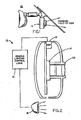
- FIG. 2 is a partial side elevation view and block diagram of a vehicle headlight dimming control system according to the present invention
- FIG. 3 is a schematic of an imaging array suitable for use with the control system of the present invention.
- FIG. 4 is a schematic of a determination of an offset of a focus of expansion for the control system of the present invention.
- FIG. 5 is a schematic of a headlamp control system utilizing a cell phone camera for capturing images of a forward field of view.
- a vehicle 10 includes an automatic vehicle headlamp control system or vehicle headlamp dimming control system 12, which includes an image sensor 14 which senses light from a scene forward of vehicle 10, an imaging processor or control circuit 13 which receives data from image sensor 14 and processes the image data, and a vehicle lighting control logic module 16 which exchanges data with control circuit 13 and controls the headlamps 18 (such as by changing or retaining the state of the headlamps, such as between a higher beam state and a lower beam state) of vehicle 10 for the purpose of modifying the beam illumination state of the headlamps of the vehicle ( FIGS. 1 and 2 ).
- an image sensor 14 which senses light from a scene forward of vehicle 10
- an imaging processor or control circuit 13 which receives data from image sensor 14 and processes the image data
- a vehicle lighting control logic module 16 which exchanges data with control circuit 13 and controls the headlamps 18 (such as by changing or retaining the state of the headlamps, such as between a higher beam state and a lower beam state) of vehicle 10 for the purpose of modifying the beam illumination
- the headlamps are operable to selectively emit a light output via a high beam lighting element and a lower beam or low beam lighting element.
- Headlamp dimming control 12 is operable to determine whether light sources in the image captured by the image sensor are or may be indicative of headlamps of oncoming vehicles or taillights of leading vehicles and is operable to adjust the headlamps of the controlled vehicle between a high beam state and a lower beam state or low beam state in response to such a determination.
- Headlamp dimming control 12 may utilize the principles disclosed in U.S. Pat. Nos.
- Headlamp control 12 is operable to distinguish the light sources captured in the image between light sources representing headlamps and/or taillights of other vehicles, as discussed below.
- the imaging sensor for the headlamp control may comprise any suitable sensor, and may utilize various imaging sensors or imaging array sensors or cameras or the like, such as a CMOS imaging array sensor, a CCD sensor or other sensors or the like, such as the types described in U.S. Pat. Nos.
- the control 12 may include a lens element or optic 20 between the image sensor and the forward scene to substantially focus the scene at an image plane of the image sensor.
- the optic may comprise an asymmetric optic, which focuses a generally central portion of the scene onto the image sensor, while providing classical distortion on the periphery of the scene or field of view.
- Such imaging sensors or cameras are pixelated imaging array sensors having a photosensing array 15 of a plurality of photon accumulating or photosensing light sensors or pixels 15a ( FIG. 3 ), which are arranged in a two-dimensional array of rows and columns on a semiconductor substrate.
- the camera established on the substrate or circuit board includes circuitry which is operable to individually access each photosensor pixel or element of the array of photosensor pixels and to provide an output or image data set associated with the individual signals to the control circuit 13, such as via an analog to digital converter (not shown).
- the control circuit 13 may then be operable to process the signal from at least some of the pixels to analyze the image data of the captured image, as discussed below. As shown in FIG.
- the control may process one or more sub-arrays 15b of the photosensor array 15, where a particular sub-array may be representative of a zone or region of interest in the forward field of view of the camera.
- the control may process the sub-array of pixels while ignoring other pixels or processing other pixels at a reduced level (such as by utilizing aspects of the systems described in U.S. Pat. No.
- control may process the sub-array of pixels in a particular manner (such as to determine if a light source is a vehicle lamp in the regions forward of the vehicle and near the host vehicle's path of travel, such as a headlamp of an oncoming vehicle in a lane adjacent to (such as to the left of) the host vehicle or other vehicle lamp forward and/or to the left or right of the host vehicle) while processing other sub-arrays or pixels in a different manner.
- a light source is a vehicle lamp in the regions forward of the vehicle and near the host vehicle's path of travel, such as a headlamp of an oncoming vehicle in a lane adjacent to (such as to the left of) the host vehicle or other vehicle lamp forward and/or to the left or right of the host vehicle
- the headlamp control system or at least the imaging device or camera is preferably mounted centrally at or near the upper inside surface of the front windshield of a vehicle and with a forward field of view through the region cleaned or wiped by the windshield wipers.
- the imaging device may be mounted at an interior rearview mirror assembly (such as at a mounting bracket or base of the mirror assembly) or at an accessory module or windshield electronics module disposed at or near the interior rearview mirror assembly and at or near the interior surface of the vehicle windshield.
- Automatic image-based high beam control systems in which an image of the scene forward of the vehicle is focused by an optical system, may have a horizontal field of view equal to, but not limited to, approximately +/- 24 degrees about the imaging system centerline. This horizontal field of view may be larger than (and may be substantially larger than) the horizontal extent of the high beam pattern, but optionally the high beam pattern itself may be moved left and right up to approximately 15 degrees in either direction by an adaptive front lighting (AFL) system.
- the image may be focused or imaged onto a rectangular array image capture device, such as, but not limited to, onto a 640 x 480 CMOS color imager, which captures image data and provides sequential frames of data indicative of the light energy reflected or emitted by objects in the region subtended by each element of the array.
- the image capture rate may be at a rate in the range of about 5 to 120 times per second or more, with processing being performed on the data to determine the presence, location and characteristics of objects and/or light sources within the monitored scene and to determine characteristics of the monitored scene, such as general illumination level, and to utilize several defined regions or zones of the monitored scene for various purposes.
- the region of the scene that generally corresponds to the region of influence of the vehicle high beam pattern may be used to determine the appropriate high beam state of the headlamps depending on whether or not other road users are detected within that region.
- the regions to the left and right of the first region may be used to anticipate the upcoming entry of other road users into the first region in order to facilitate a rapid and appropriate response upon entry or just prior to entry of the first region.
- the upper central region of the monitored scene may be used to determine ambient lighting conditions such that a first threshold may be established below which low beam headlights are activated, and a second threshold may be established above which high beam activation may be inhibited, while the lower horizontal portion of the ambient lighting condition detection region may be used to detect urban lighting conditions or the like.
- Other processing of the captured image data may be implemented depending on the particular application of the image sensor and processor.
- the control system thus captures images or generates image data indicative of the scene occurring forwardly of the vehicle and processes the image data to determine whether or not a headlamp or taillight of another vehicle is present, whereby the headlamps of the controlled vehicle may be adjusted between their high and low beams accordingly.
- the image processor processes one or more zones of interest or regions of interest to determine whether the detected light source is a headlamp or taillight of another vehicle traveling on the same road as the controlled vehicle (since a light detected that is remote from the particular or appropriate region of interest is not likely another vehicle light or is not likely relevant to the decision as to whether or not the controlled vehicle's headlamps should be adjusted).
- the control system thus may utilize aspects of the image systems and/or headlamp control systems described above to process different zones or regions of interest, and may ignore other regions of the captured images or process other regions at a reduced level (such as by utilizing aspects of the systems described in U.S. Pat. Nos. 5,550,677 ; 5,877,897 ; and/or 7,038,577 ).
- control system is operable to provide an automatic alignment or correction factor of the image data captured by the image sensor.
- the various regions of interest within the scene monitored by the sensor are optimally maintained regardless of vehicle and high beam control system module geometric manufacturing and assembly tolerances, and other sources of misalignment, such as vehicle pitch and yaw variations due to a wide range of possible vehicle loading conditions.
- Typical vehicle body structures, windshields and assembly systems of vehicles may contribute to geometric tolerances associated with the surface to which the headlamp control system module is attached. It is not unusual to encounter a total stack up of tolerances which result in a potential vertical and horizontal misalignment of approximately +/- 4 degrees from the theoretically ideal condition. This is a significant value and may result in errors in processing the appropriate region of interest and/or determining lane widths and object sizes and distances and the like.
- such adjustment will only correct for misalignment of the imaging device and system at the time of manufacturing of the vehicle, and will not correct or account for or adapt the system for misalignment that may occur during use, such as due to a physical or mechanical misalignment of the imaging device or due to different load balancing of the vehicle or replacement of the camera or mirror assembly or assembly module or windshield and/or the like.
- a typical vehicle experiences many different loading conditions which cause it to adopt a wide range of pitch and roll attitudes, causing an automatic headlamp control system of the vehicle to view the forward scene from perspectives different from the ideal, or initially considered design conditions, and thereby potentially resulting in different headlight actuation decisions than contemplated by the original system specifcation.
- the headlamp control system it is beneficial for the headlamp control system to include a feature which automatically compensates for an initial misalignment condition and additionally is capable of correcting for temporary vehicle conditions and re-installation misalignments which may occur during the use of the vehicle.
- the particular point in the forward scene may be defined as a particular distant point or area which lies on the forward extended vehicle centerline on the horizontal plane which passes generally through the center of the optical system associated with the image capture device.
- the distant point may be the point within the forward scene at which the headlights of an oncoming vehicle or the tail lamps of a slower leading vehicle are first detected.
- the image of the target vehicle expands within the imaged scene, towards the left if traveling in a leftward lane, centrally if in the same lane, and towards the right if traveling in a rightward lane.
- FOE focus of expansion
- the control system may monitor the controlled vehicle trajectory until it reaches the point in the road where the new light source would have been initially detected in order to confirm that the road traveled for the duration of the monitoring period was substantially flat and substantially straight. If it is determined that the point or light source was a light source of a leading or approaching vehicle and the controlled vehicle and approaching vehicle are traveling along a substantially flat and substantially straight road, the location of the initial distant point or FOE may be compared to an expected location (the location of the pixel corresponding to the preset or expected FOE) to determine if there is an offset or error in the imaging device's or system's calibration.
- the control system optionally, and preferably, collects or processes or analyzes many new light sources and picks the best samples and averages them to arrive at the best or optimal or enhanced FOE.
- the image processor determines the degree of offset and adjusts or shifts the regions of interest parameters or coordinates or targeted pixels to accommodate for the offset, such that the processor processes the image data captured by the pixels representative of the appropriate zones or regions of interest forwardly of the controlled vehicle for detecting headlamps of approaching vehicles and taillights of leading vehicles. For example, if the detected FOE is ten pixels to the left and five pixels down from the expected FOE, the processor may readily adjust the parameters or coordinates of the regions of interest by that amount (or by a scaled value based on the detected offset). Thus, the headlamp control system may adjust the processing to adapt to shifts or changes in the FOE of the imaging device and thus may do so electronically and without physical or mechanical adjustment of the imaging device relative to the vehicle.
- the headlamp control system thus provides a low cost processing adjustment to maintain processing of the appropriate regions of interest when detecting light sources or objects forwardly of the vehicle and determining whether or not the detected light sources or objects are leading vehicles or approaching vehicles along the road on which the controlled vehicle is traveling.
- the control system thus calibrates or adapts the image data or image processing to accommodate for manufacturing tolerances and/or physical misalignment that may occur during the camera and/or mirror or accessory module manufacture or during the vehicle manufacture, and to accommodate for misalignment or shifts in the principal viewing axis of the camera or imaging device due to different load balancing of the vehicle or distortion in shape of the headlamp control system assembly due to heating and/or other situations where the vehicle encounters or experiences a change in pitch or tilt or yaw of the vehicle.
- control system may be adjusted in response to a detection of lane markers, such as along a straight and/or flat road (or optionally along a curved road and optionally in conjunction with a steering angle of the vehicle).
- lane markers such as along a straight and/or flat road (or optionally along a curved road and optionally in conjunction with a steering angle of the vehicle).
- the system may detect lane markers 22 along the lane in which the controlled vehicle is traveling and, if the lane markers are substantially straight, may determine an intersection 22a of the lane markers.
- the control system may detect headlamps in front of the vehicle and may monitor the appearance point 24 of the detected headlamps.
- the system may monitor the appearance point and the intersection point as it travels toward and past the physical locations corresponding to the monitored points in the captured images, and if it is determined that the road or lane was substantially straight, the offset between the actual FOE and the expected FOE may be determined.
- the control system collects determined lane-marker-based FOE samples and rejects the error samples and averages them to arrive at a best or optimal or enhanced lane-marker-based FOE.
- control system may utilize a weighted sum calculation of data representative of the intersection point and the (appearance point plus offset) to determine the actual FOE, depending on the particular application.
- control system may be adjusted in response to vehicle pitch information from a bus or accelerometer, and/or vehicle roll information from an accelerometer or bus information of the vehicle, and/or vehicle yaw information from an accelerometer or bus information of the vehicle.
- system may only monitor for new light sources when the vehicle is traveling in a substantially straight line (such as when the steering wheel angle is between, for example, about 0 +/- 10 degrees for a vehicle with steering ratio of about 17, or at or between any other suitable or selected threshold angle or angles depending on the particular application of the control system).
- adjustment and/or alignment of the image sensor may occur by tracking movement of light sources through the images when the vehicle is traveling substantially straight, so that the control may compare the tracked light sources to expected locations and paths through the captured images as the vehicle moves along the substantially straight path and may adjust the processing parameters of the image processor and imaging sensor accordingly.
- control system may determine the actual FOE and offset along curved road sections in response to the lane marker detection and/or a steering angle input, whereby the system may monitor the detected appearing light source and monitor its initial or appearance location as the controlled vehicle approaches the initial location.
- the control system may monitor or track the initial location to determine if the controlled vehicle approaches or arrives at or near that location.
- the control system may also determine if the detected light source was a headlamp of an approaching vehicle or taillight of a leading vehicle and, if so, may determine the offset and adjust or adapt the image processing accordingly.
- the automatic adjustment or correction or adaptation of the image processor in response to a detected offset between a detected FOE and an expected FOE allows the control system to utilize various cameras or imaging devices, such as aftermarket devices or cell phone cameras or the like.
- an aftermarket camera may be installed in the vehicle with a generally forward field of view in the direction of travel of the vehicle, and the system may, as the vehicle is then driven, determine an offset or error in the expected FOE and readily compensate for such offset, without requiring any further manual input or physical adjustments.
- any imaging device such as, for example, a cell phone camera
- a cell phone 26 may be docked at (such as at a phone connector mount or port 28 or the like at the vehicle instrument panel or dashboard 29 or mirror assembly or accessory module or console or the like) or in communication with an image processor that processes the images captured by the cell phone camera 26a in a similar manner as described above, and determines the current FOE for the cell phone camera at its present orientation relative to the vehicle and determines the appropriate zones of interest or regions of interest for processing the image data to determine if detected light sources in the forward field of view are representative of a headlamp of an approaching vehicle or taillight of a leading vehicle.
- the cell phone may transmit a compressed video stream (such as, for example, at about 264 Hz) to a cell phone network, and/or may communicate video signals to an on-board or vehicle-based processor.
- the adaptive FOE process allows for the use of various aftermarket cameras and/or cell phone cameras for various imaging systems or applications, such as adaptive front lighting systems or lane departure warning systems or object detection systems or collision avoidance systems or the like, since the camera (such as a cell phone and camera) may be located at or in or mounted at the vehicle and the processing of the image data may be adapted to automatically accommodate for and correct for any misalignment or mis-mounting or mis-positioning of the camera.
- aspects of the adaptive FOE system described above may be utilized for cameras (such as OEM cameras or aftermarket cameras or cell phone cameras or the like) having a rearward field of view so that the processing of the captured images is corrected or adapted and the images are processed accordingly, such as for a rearvision system or backup aid or the like, and/or may be utilized for cameras having a field of view directed inside the vehicle, such as for interior cabin monitoring systems or the like (such as utilizing aspects of the systems described in U.S. Pat. Nos. 5,760,962 ; 5,877,897 ; and/or 6,690,268 ).
- the image data from the cell phone camera may be communicated wirelessly (such as via a short-range radio frequency communication, such as via a BLUETOOTH ® communication protocol or the like) or via a wired connection (such as via a docking port or USB port or the like at the vehicle) to a vehicle-based or onboard processor (such as processor 13 described above), or compressed video data or image output of the camera may be streamed to a cell phone network or the like.
- a short-range radio frequency communication such as via a BLUETOOTH ® communication protocol or the like
- a wired connection such as via a docking port or USB port or the like at the vehicle
- a vehicle-based or onboard processor such as processor 13 described above
- control system may adjust the zones of interest or regions of interest in the captured images in response to an input representative of the vehicle trajectory, such as in response to a steering angle of the vehicle or steering wheel angle of the vehicle, such as by utilizing aspects of the systems described in U.S. patent application Ser. No. 11/315,675, filed Dec. 22, 2005 , and published Aug. 17, 2006 as U.S. Publication No, US-2006-0184297 ; and/or PCT Application No. PCT/US2007/075702, filed Aug. 10, 2007 , and published Feb. 28, 2008 as PCT Publication No. WO 2008/024639 .
- the zones of interest or regions of interest may be adjusted or offset (i.e., the image processor may process different groups of pixels corresponding to the different zones or regions of interest) so that the image processor processes the adjusted or offset zones or regions of interest to detect vehicles along a curved road.
- the zones of interest parameters or pixel locations may occur when the control system determines that the controlled vehicle is traveling along a curved road, such as in response to a steering angle input or lane detection input or the like.
- the regions of interest may be reduced or shrunk (or optionally extended) at the corresponding side regions depending on the direction of the curve along which the vehicle is traveling.
- control system may adjust or adapt other processing parameters based on previous image processing.
- the control system may process a large window or region of interest and may adapt the region of interest to a smaller region or window if a light source is detected.
- the region of interest may be adapted from a large region or zone or window to a smaller or predicted region that is representative of where the headlamps of an approaching vehicle should be located relative to the controlled vehicle, such as down and to the left in the captured image (for a detected taillight, the adaptive region or window may be generally downward at or near a center line of the image as the controlled vehicle approaches a leading vehicle).
- the control system may resume processing of the larger region of interest or window to determine if other light sources or objects are present.
- the exposure may be adjusted or adapted from one frame to the next, such as if an approaching headlamp is detected, for example, the exposure may be less for the subsequent frames as the headlamp moves closer to the controlled vehicle.
- the change in exposure may be reduced or inhibited, since the taillights typically move generally with the controlled vehicle and do not approach the controlled vehicle as rapidly as to headlamps of approaching vehicles.
- the driving side of the road varies by countries of the world (for example, in the United States, the vehicles are driven on the right side of the road). It is desirable to support left and right driving side of road to reduce engineering and manufacturing cost.
- the head lamp control system may be operable to process the image data set to detect the new light source and identify the head light of the oncoming vehicle.
- the control system tracks the head light of the detected oncoming vehicle and stores the trajectory of headlight.
- the driving side of the vehicle (the side of the road along which the vehicle is traveling) is identified by analyzing a pre-determined amount of the trajectories of the oncoming vehicles.
- the control system may detect the driving side only by analyzing the location of appearance of new headlights in image data, since the appearance of new head light sources is biased toward one side of the captured image or image data according the driving side of the road when the vehicle is traveling along a substantially flat and straight road.
- the control system may be responsive to a global positioning system input and may determine the driving side of the road on which the vehicle is traveling based on the geographical location of the vehicle and the driving rules and regulations of that geographical location or region.
- the automatic high beam system or automatic headlamp control system may be optimized to adapt the vehicle for enhanced performance for the particular road (and side of the road) along which the vehicle is being driven.
- the control system may modify many calibrations or parameters such as, but not limited to, different zones or sub-arrays of image data, weighting factors of different zones of image data, offset of the FOE, automotive light sources acceptance parameters, lane marker detection and tracking of objects and light sources and/or the like, in order to adapt the system for enhanced performance depending on which side of the road the host vehicle is driven on.
- control system may be operable to provide a low-cost processing of the image data via processing captured frames of image data at different resolution levels, such as at least two different resolutions or resolution levels.
- the control system may process images at a higher resolution level (where the imaging device may be processed, for example, as a pixelated array of 640 x 480 pixels), at a medium or intermediate resolution (where the imaging device may be processed, for example, as a pixelated array of 320 x 240 pixels), and at a lower resolution (where the imaging device may be processed, for example, as a pixelated array of 160 x 120 pixels).
- Such a processing technique allows the processor to use the same classifier (such as the same window size or mask size, such as about a 2 x 3 pixel mask for detecting a distant taillight) for detecting and identifying taillights (or other light sources) at each distance or range, and thus may substantially reduce the memory requirements of the processor.
- the same classifier such as the same window size or mask size, such as about a 2 x 3 pixel mask for detecting a distant taillight
- taillights or other light sources
- the processor may utilize a 2 x 3 pixel mask to determine if the detected light source is about the expected size of a taillight to assist in correctly identifying the taillights.
- the processor would process the image data with a larger mask or window because the light source would be larger when it is closer to the controlled vehicle.
- the control system requires sufficient memory capability to store the different window sizes for detecting the various light sources at various distances in front of the controlled vehicle. Such memory or data storage can be costly and thus may add to the cost of the headlamp control system (or other vision-based system).
- the system may generally equalize the sizes of the imaged objects or light sources for the various distances from the controlled vehicle, so that only a single sized mask or window need be utilized for identifying a particular light source, such as a taillight of a leading vehicle.
- a taillight at about 200 meters may take up a window of about 2 x 3 pixels of a 640 x 480 higher resolution image, while a taillight at about 100 meters or thereabouts may take up a window of about 2 x 3 pixels of a 320 x 240 medium resolution image (which would be about a 4 x 6 pixel window if it were a higher resolution image), and a taillight at about 50 meters or less may take up a window of about 2 x 3 pixels of a 160 x 120 lower resolution image (which would be about a 8 x 12 pixel window if it were a higher resolution image).
- the control system may utilize the same mask or window or classifier for identifying a detected light source.
- the intensity of the detected light sources would be different (such as, for example, the intensity of the light source of the medium resolution image may be eight times the intensity of the light source of the low resolution image and the intensity of the light source of the high resolution image may be 64 times the intensity of the light source of the low resolution image), this can be readily accounted for when detecting the light source and identifying the detected light source.
- the processor may process the image data with a single classifier (such as for classifying the light source as a taillight) regardless of the distance to the detected light source from the controlled vehicle, and thus, the memory requirements of the system for multiple classifiers may be substantially reduced to reduce the cost of the control system.
- a single classifier such as for classifying the light source as a taillight
- control system may be operable to superimpose a code or flicker on the headlight beams to communicate a code or message to control systems of other vehicles or of roadside monitors or stations, such as by utilizing aspects of the systems described in U.S. Pat. No. 7,004,606 .
- the headlamps or other vehicle lights
- Such a code would be camouflaged to people viewing the headlamps or other lights, but visible to the machine vision systems of the other vehicles.
- Different flicker rates or different color combinations or spectral signature of the lights may communicate different codes, and the codes may be preset codes (such as, for example, a code that communicates to the driver of the other vehicle or vehicles that there is an accident ahead or the like), or may be entered by the driver of the controlled vehicle (such as via a voice input or manual input or the like).
- preset codes such as, for example, a code that communicates to the driver of the other vehicle or vehicles that there is an accident ahead or the like
- the codes may be entered by the driver of the controlled vehicle (such as via a voice input or manual input or the like).
- messages may be sent from the controlled vehicle to other vehicles via the code embedded in or superimposed on the output signal or illumination signal of the vehicle lights.
- a code or message may be communicated from a controlled vehicle passing an accident to all similarly equipped oncoming traffic to alert the oncoming traffic of the accident.
- the code may comprise a color change (such as a subtle color change) in the color of the light emitted by the vehicle light source or a flicker (such as a high frequency flicker that is not readily noticeable or discernible to a human observer) or the like, and may be readily detected and identified or decoded by a similar control system of another vehicle.
- the vehicle light source may comprise yellow and blue LEDs flickering at a predetermined rate and pattern and can thus encode information or data or messages which would look like a typical white HID or halogen headlight to human observers.
- Human perception of flickering in this color pair is worse than other colors which could also produce white, such as those nearer the red and green colors.
- This flicker rate of the yellow and blue LEDs thus may be lower than other color combinations (while still avoiding detection by the human observers), such as less than about 60 Hz.
- the taillights may also or otherwise be flickered or adjusted or coded to communicate a message or data.
- Red taillight location in color space may not be optimal for flickering different colors, but using flicker rates above about 60 Hz can provide the desired communication means while limiting or substantially avoiding human detection.
- the light sources may flicker or may have superimposed thereon an illumination output in the infrared or near infrared range of the spectrum, where humans have poor sensitivity, and where the imaging devices may be highly sensitive.
- control system may be operable to determine if a pixel or pixels of the imaging array is either inoperable or "bad" or blocked, so that the control system may ignore the bad/blocked pixel output to avoid adversely affecting averages of pixel output intensities during the image processing.
- the bad pixel detection process or algorithm may be performed periodically when the system is operating. For example, a captured frame or image may be dedicated to bad pixel detection. If a bad pixel or pixels is/are detected, averaging of the output intensities of the pixels surrounding the bad pixel may be performed to accommodate or replace the bad or inoperable pixel.
- control system may be operable to determine if some or all of the pixels of the imaging array are blocked (such as via an object or dirt or debris at the vehicle windshield or the like) and to adapt the image processing accordingly or notify or alert the driver of the vehicle that such blockage has occurred.
- a partial or total day blockage algorithm may be run during daytime lighting conditions, such as in response to a user input or on demand, while a partial or total night blockage algorithm may be run when the ambient condition is indicative of nighttime lighting conditions.
- the control system may conclude that the imaging device substantially or totally blocked.
- the control system may perform region-based processing to take into account intensity variations in different regions of the pixelated imaging array. Based on intensity variations with neighboring or adjacent regions and the continuity of the variations over time, the control may determine that the imaging array is partially blocked. The control system may process the blocked pixel region in a night mode to reduce or substantially preclude the possibility of a false blockage detection.
- the system may adapt the image processing to accommodate the blocked pixels, or the system may alert the driver of the vehicle that the pixels are blocked so that the driver or user may unblock the imaging device (such as via cleaning the windshield of the vehicle), or the system may actuate the vehicle windshield wipers to clear the windshield at the imaging device or the like, or the system may actuate a blower system (such as a defogger system or the like) of the vehicle to direct or force or blow air toward the detected blockage to clear the windshield or window or area in the forward field of view of the imaging device.
- a blower system such as a defogger system or the like
- the control thus may detect that at least a portion of the imaging device or photosensor array is blocked and may switch to a low beam mode in response to the detection (so as to allow the system to confirm the existence of the blockage without the high beams on during this period of time), and the system may at least one of (a) alert the driver of the subject vehicle of the detected blockage so that he or she can clean the windshield or sensor or otherwise remove the blockage or actuate the wipers and/or related system of the vehicle to remove the blockage; (b) automatically actuate a wiper (such as the windshield wipers) of the vehicle to remove the blockage from the forward field of view of the imaging device; and (c) automatically actuate a blower system of the vehicle to remove or dissipate the blockage from the forward field of view.
- the system or control may also detect that the blockage has been removed from the forward field of view and may resume the normal functionality of the headlamp control system and/or the wiper system of the vehicle and/or the blower system of the vehicle.
Abstract
Description
- The present invention relates to automatic headlamp control systems for vehicles and, more particularly, to automatic headlamp control systems that automatically adjust the high and low beam states of a vehicle headlamp.
- Automotive forward lighting systems are evolving in several areas including the use of image-based sensors, typically referred to as Automatic High Beam (AHB) control systems, to maximize the use of high beam road illumination when appropriate, the use of steerable beam systems, typically referred to as Adaptive Front Lighting (AFL) systems, to provide a greater range of beam pattern options particularly for driving on curved roads or during turn maneuvers wherein the beam pattern may be biased or supplemented in the direction of the curve or turn, and the combination of such AHB and AFL systems.
- Automatic high beam control system are known that utilize an optical system, an image sensor, and signal processing including spectral, spatial and temporal techniques to determine ambient lighting conditions, the road environment, and the presence of other road users in order to automatically control the selection of the appropriate forward lighting state such that user forward vision is optimized while minimizing the impact of headlamp caused glare on other road users in all lighting conditions. Examples of such systems are described in
U.S. Pat. Nos. 5,796,094 ;6,097,023 ;6,320,176 ;6,559,435 ;6,831,261 ;6,396,397 ;6,822,563 ; and7,004,606 . - While AHB systems that utilize the features and concepts described within the above identified U.S. patents have achieved performance levels that have resulted in considerable commercial success, it is desired to provide additional features and techniques, which may increase the utility, improve the performance, facilitate the manufacture, and simplify the installation of such systems.
- The present invention provides an automatic headlamp control system that is operable to automatically control or adjust the high beam state of a vehicle's headlamps. The headlamp control system is operable to determine a focus of expansion pixel or pixels in the captured image and adjust the image processing in response to the location or pixel/pixels of the focus of expansion and the tracking of movement of detected light sources and other objects as the vehicle travels along the road. The headlamp control system of the present invention may provide reduced processing of image data to provide a low cost system.
- According to an aspect of the present invention, a vehicular imaging system comprises a photosensor array comprising a plurality of photosensor elements and a control responsive to an output of the photosensor array. The photosensor array has a field of view forward of the vehicle that is generally in line with the vehicle's primary direction of forward travel. The photosensor array captures images of an area encompassed by the forward field of view. The control processes an image data set indicative of captured images. The control processes a reduced image data set of the image data set to determine whether an object of interest is within a target zone of the captured images. The reduced image data set is representative of a portion of the captured images as captured by a particular grouping of the photosensor elements. Responsive to a determination of a change in a focus of expansion of the captured images, the control adjusts the reduced image data set so as to be representative of a portion of the captured images as captured by a different particular grouping of the photosensor elements.
- The control may be operable to adjust a state of a headlamp beam in response to the image processing. The focus of expansion comprises at least one photosensor element that initially detects a new light source in the field of view. The control may track the new light source as it expands in the captured images (such as while the relative distance between the controlled vehicle and the new light source decreases) to confirm that the new light source is indicative of an object of interest. The control may determine that the new light source is representative of a light source of a leading or approaching vehicle and the controlled vehicle and approaching vehicle are traveling along a substantially flat and substantially straight road, and the control may compare a location of the new light source (such as when it is at or near the targeted zone of interest) to an expected location of the light source to determine if there is an offset. The control may process many samples of new light sources to arrive at an optimal or enhanced offset. The control adjusts the reduced data set in response to determination of such an offset.
- According to another aspect of the present invention, a vehicular imaging system includes a photosensor array having a plurality of photosensor elements and a control responsive to an output of the photosensor array. The photosensor array has a field of view forward of the vehicle that is generally in line with the vehicle's primary direction of forward travel. The photosensor array captures images of an area encompassed by the forward field of view. The control processes image data indicative of captured images, and is operable to selectively process the output of the photosensor array as an output from the photosensor array at two or more different resolutions. The control utilizes a single classifying parameter for identifying a particular object of interest in the forward field of view for all of the at least two resolutions.
- Optionally, for example, the at least two different resolutions may comprise (a) an output of a higher resolution photosensor array, (b) an output of a medium resolution photosensor array, and (c) an output of a lower resolution photosensor array. The control may process the output of the photosensor array at different resolutions in response to one of (a) a location of a detected light source and (b) a distance between the subject vehicle and a detected light source.
- These and other objects, advantages, purposes and features of the present invention will become apparent upon review of the following specification in conjunction with the drawings.
-
FIG. 1 is a side elevation of a portion of a vehicle embodying the present invention; -
FIG. 2 is a partial side elevation view and block diagram of a vehicle headlight dimming control system according to the present invention; -
FIG. 3 is a schematic of an imaging array suitable for use with the control system of the present invention; -
FIG. 4 is a schematic of a determination of an offset of a focus of expansion for the control system of the present invention; and -
FIG. 5 is a schematic of a headlamp control system utilizing a cell phone camera for capturing images of a forward field of view. - Referring now to the drawings and the illustrative embodiments depicted therein, a
vehicle 10 includes an automatic vehicle headlamp control system or vehicle headlampdimming control system 12, which includes an image sensor 14 which senses light from a scene forward ofvehicle 10, an imaging processor orcontrol circuit 13 which receives data from image sensor 14 and processes the image data, and a vehicle lightingcontrol logic module 16 which exchanges data withcontrol circuit 13 and controls the headlamps 18 (such as by changing or retaining the state of the headlamps, such as between a higher beam state and a lower beam state) ofvehicle 10 for the purpose of modifying the beam illumination state of the headlamps of the vehicle (FIGS. 1 and 2 ). The headlamps are operable to selectively emit a light output via a high beam lighting element and a lower beam or low beam lighting element.Headlamp dimming control 12 is operable to determine whether light sources in the image captured by the image sensor are or may be indicative of headlamps of oncoming vehicles or taillights of leading vehicles and is operable to adjust the headlamps of the controlled vehicle between a high beam state and a lower beam state or low beam state in response to such a determination.Headlamp dimming control 12 may utilize the principles disclosed inU.S. Pat. Nos. 5,796,094 ;6,097,023 ;6,320,176 ;6,559,435 ;6,831,261 ;6,396,397 ;6,822,563 ; and/or7,004,606 .Headlamp control 12 is operable to distinguish the light sources captured in the image between light sources representing headlamps and/or taillights of other vehicles, as discussed below. - The imaging sensor for the headlamp control may comprise any suitable sensor, and may utilize various imaging sensors or imaging array sensors or cameras or the like, such as a CMOS imaging array sensor, a CCD sensor or other sensors or the like, such as the types described in
U.S. Pat. Nos. 5,550,677 ;5,670,935 ;5,760,962 ;5,715,093 ;5,877,897 ;6,498,620 ;5,796,094 ;6,097,023 ;6,320,176 ;6,559,435 ;6,831,261 ;6,806,452 ;6,396,397 ;6,822,563 ;6,946,978 ;7,038,577 ; and/or7,004,606 ; and/orU.S. patent application Ser. No. 11/315,675, filed Dec. 22, 2005 US-2006-0184297A1 ; and/orPCT Application No. PCT/US2007/075702, filed Aug. 10, 2007 , and published Feb. 28, 2008 asPCT Publication No. WO 2008/024639 , and/or PCT Application No.PCT/US2003/036177, filed Nov. 14, 2003 , and published Jun. 3, 2004 asPCT Publication No. WO 2004/047421 A3 . Thecontrol 12 may include a lens element or optic 20 between the image sensor and the forward scene to substantially focus the scene at an image plane of the image sensor. Optionally, the optic may comprise an asymmetric optic, which focuses a generally central portion of the scene onto the image sensor, while providing classical distortion on the periphery of the scene or field of view.
Such imaging sensors or cameras are pixelated imaging array sensors having aphotosensing array 15 of a plurality of photon accumulating or photosensing light sensors orpixels 15a (FIG. 3 ), which are arranged in a two-dimensional array of rows and columns on a semiconductor substrate. The camera established on the substrate or circuit board includes circuitry which is operable to individually access each photosensor pixel or element of the array of photosensor pixels and to provide an output or image data set associated with the individual signals to thecontrol circuit 13, such as via an analog to digital converter (not shown). As camera 14 receives light from objects and/or light sources in the target scene, thecontrol circuit 13 may then be operable to process the signal from at least some of the pixels to analyze the image data of the captured image, as discussed below.
As shown inFIG. 3 , the control may process one or more sub-arrays 15b of thephotosensor array 15, where a particular sub-array may be representative of a zone or region of interest in the forward field of view of the camera. The control may process the sub-array of pixels while ignoring other pixels or processing other pixels at a reduced level (such as by utilizing aspects of the systems described inU.S. Pat. No. 7,038,577 ), and/or the control may process the sub-array of pixels in a particular manner (such as to determine if a light source is a vehicle lamp in the regions forward of the vehicle and near the host vehicle's path of travel, such as a headlamp of an oncoming vehicle in a lane adjacent to (such as to the left of) the host vehicle or other vehicle lamp forward and/or to the left or right of the host vehicle) while processing other sub-arrays or pixels in a different manner. - In order to take advantage of the environmental protection offered by the vehicle cabin, the frequently cleaned optically clear path offered by the vehicle windshield (which is cleaned or wiped by the windshield wipers when the wipers are activated), and the relatively high vantage point offered at the upper region or top of the windshield, the headlamp control system or at least the imaging device or camera is preferably mounted centrally at or near the upper inside surface of the front windshield of a vehicle and with a forward field of view through the region cleaned or wiped by the windshield wipers. The imaging device may be mounted at an interior rearview mirror assembly (such as at a mounting bracket or base of the mirror assembly) or at an accessory module or windshield electronics module disposed at or near the interior rearview mirror assembly and at or near the interior surface of the vehicle windshield.
- Automatic image-based high beam control systems, in which an image of the scene forward of the vehicle is focused by an optical system, may have a horizontal field of view equal to, but not limited to, approximately +/- 24 degrees about the imaging system centerline. This horizontal field of view may be larger than (and may be substantially larger than) the horizontal extent of the high beam pattern, but optionally the high beam pattern itself may be moved left and right up to approximately 15 degrees in either direction by an adaptive front lighting (AFL) system. The image may be focused or imaged onto a rectangular array image capture device, such as, but not limited to, onto a 640 x 480 CMOS color imager, which captures image data and provides sequential frames of data indicative of the light energy reflected or emitted by objects in the region subtended by each element of the array. The image capture rate may be at a rate in the range of about 5 to 120 times per second or more, with processing being performed on the data to determine the presence, location and characteristics of objects and/or light sources within the monitored scene and to determine characteristics of the monitored scene, such as general illumination level, and to utilize several defined regions or zones of the monitored scene for various purposes. For example, the region of the scene that generally corresponds to the region of influence of the vehicle high beam pattern may be used to determine the appropriate high beam state of the headlamps depending on whether or not other road users are detected within that region. Optionally, the regions to the left and right of the first region may be used to anticipate the upcoming entry of other road users into the first region in order to facilitate a rapid and appropriate response upon entry or just prior to entry of the first region. The upper central region of the monitored scene may be used to determine ambient lighting conditions such that a first threshold may be established below which low beam headlights are activated, and a second threshold may be established above which high beam activation may be inhibited, while the lower horizontal portion of the ambient lighting condition detection region may be used to detect urban lighting conditions or the like. Other processing of the captured image data may be implemented depending on the particular application of the image sensor and processor.
- The control system thus captures images or generates image data indicative of the scene occurring forwardly of the vehicle and processes the image data to determine whether or not a headlamp or taillight of another vehicle is present, whereby the headlamps of the controlled vehicle may be adjusted between their high and low beams accordingly. The image processor processes one or more zones of interest or regions of interest to determine whether the detected light source is a headlamp or taillight of another vehicle traveling on the same road as the controlled vehicle (since a light detected that is remote from the particular or appropriate region of interest is not likely another vehicle light or is not likely relevant to the decision as to whether or not the controlled vehicle's headlamps should be adjusted). The control system thus may utilize aspects of the image systems and/or headlamp control systems described above to process different zones or regions of interest, and may ignore other regions of the captured images or process other regions at a reduced level (such as by utilizing aspects of the systems described in
U.S. Pat. Nos. 5,550,677 ;5,877,897 ; and/or7,038,577 ). - In order to ensure that the region of interest or regions of interest being processed are representative of the appropriate region relative to the controlled vehicle and direction of travel thereof, the control system is operable to provide an automatic alignment or correction factor of the image data captured by the image sensor. Thus, the various regions of interest within the scene monitored by the sensor are optimally maintained regardless of vehicle and high beam control system module geometric manufacturing and assembly tolerances, and other sources of misalignment, such as vehicle pitch and yaw variations due to a wide range of possible vehicle loading conditions.
- Typical vehicle body structures, windshields and assembly systems of vehicles may contribute to geometric tolerances associated with the surface to which the headlamp control system module is attached. It is not unusual to encounter a total stack up of tolerances which result in a potential vertical and horizontal misalignment of approximately +/- 4 degrees from the theoretically ideal condition. This is a significant value and may result in errors in processing the appropriate region of interest and/or determining lane widths and object sizes and distances and the like.
- It is known to provide a mechanical adjustment means to allow for the correction of such a misalignment at the installation of a headlamp control system to the vehicle. Such mechanical adjustments are, however, often undesirable since it is often expensive to apply manual labor to the alignment of components on each vehicle equipped with a headlamp control system at the vehicle assembly plant or facility. Such adjustments are additionally undesirable since the alignment procedure is then subject to operator error.
- Also, such adjustment will only correct for misalignment of the imaging device and system at the time of manufacturing of the vehicle, and will not correct or account for or adapt the system for misalignment that may occur during use, such as due to a physical or mechanical misalignment of the imaging device or due to different load balancing of the vehicle or replacement of the camera or mirror assembly or assembly module or windshield and/or the like. For example, in normal use, a typical vehicle experiences many different loading conditions which cause it to adopt a wide range of pitch and roll attitudes, causing an automatic headlamp control system of the vehicle to view the forward scene from perspectives different from the ideal, or initially considered design conditions, and thereby potentially resulting in different headlight actuation decisions than contemplated by the original system specifcation.
- Thus, it is beneficial for the headlamp control system to include a feature which automatically compensates for an initial misalignment condition and additionally is capable of correcting for temporary vehicle conditions and re-installation misalignments which may occur during the use of the vehicle. In order to achieve optimum performance of the headlamp control system, it is desirable to determine which of the array elements of the image capture device fall into each of the defined regions of interest. Since the regions are defined relative to the forward scene, it is desirable to determine a particular point or area within the forward scene and to relate that point or area to a particular array element or photosensor or group of photosensors of the image capture device.
- The particular point in the forward scene may be defined as a particular distant point or area which lies on the forward extended vehicle centerline on the horizontal plane which passes generally through the center of the optical system associated with the image capture device. When driving on a substantially flat and substantially straight road, the distant point may be the point within the forward scene at which the headlights of an oncoming vehicle or the tail lamps of a slower leading vehicle are first detected. As the distance between the controlled vehicle and target vehicle decreases, the image of the target vehicle expands within the imaged scene, towards the left if traveling in a leftward lane, centrally if in the same lane, and towards the right if traveling in a rightward lane. Thus, the described distant point may be called the focus of expansion or FOE.
- In order to determine the imaging array element or pixel which subtends the FOE in the as assembled and as loaded vehicle, it is necessary to identify the array element or pixel or pixels which first detects a new light source (which has the potential to be a vehicular light source or headlamp or taillight) within that region of the monitored scene which could potentially contain the FOE, and to continue to track the detected light source as it expands in the image as the distance between the detected source and the controlled vehicle decreases until it is confirmed that the source is a headlamp or taillight of another vehicle (such as by utilizing aspects of the systems described in
PCT Application No. PCT/US2007/075702, filed Aug. 10, 2007 , and published Feb. 28, 2008 asPCT Publication No. WO 2008/024639 ). The control system may monitor the controlled vehicle trajectory until it reaches the point in the road where the new light source would have been initially detected in order to confirm that the road traveled for the duration of the monitoring period was substantially flat and substantially straight. If it is determined that the point or light source was a light source of a leading or approaching vehicle and the controlled vehicle and approaching vehicle are traveling along a substantially flat and substantially straight road, the location of the initial distant point or FOE may be compared to an expected location (the location of the pixel corresponding to the preset or expected FOE) to determine if there is an offset or error in the imaging device's or system's calibration. The control system optionally, and preferably, collects or processes or analyzes many new light sources and picks the best samples and averages them to arrive at the best or optimal or enhanced FOE. - If an offset between the actual or detected FOE and the expected or preset FOE is detected, the image processor determines the degree of offset and adjusts or shifts the regions of interest parameters or coordinates or targeted pixels to accommodate for the offset, such that the processor processes the image data captured by the pixels representative of the appropriate zones or regions of interest forwardly of the controlled vehicle for detecting headlamps of approaching vehicles and taillights of leading vehicles. For example, if the detected FOE is ten pixels to the left and five pixels down from the expected FOE, the processor may readily adjust the parameters or coordinates of the regions of interest by that amount (or by a scaled value based on the detected offset). Thus, the headlamp control system may adjust the processing to adapt to shifts or changes in the FOE of the imaging device and thus may do so electronically and without physical or mechanical adjustment of the imaging device relative to the vehicle.
- The headlamp control system thus provides a low cost processing adjustment to maintain processing of the appropriate regions of interest when detecting light sources or objects forwardly of the vehicle and determining whether or not the detected light sources or objects are leading vehicles or approaching vehicles along the road on which the controlled vehicle is traveling. The control system thus calibrates or adapts the image data or image processing to accommodate for manufacturing tolerances and/or physical misalignment that may occur during the camera and/or mirror or accessory module manufacture or during the vehicle manufacture, and to accommodate for misalignment or shifts in the principal viewing axis of the camera or imaging device due to different load balancing of the vehicle or distortion in shape of the headlamp control system assembly due to heating and/or other situations where the vehicle encounters or experiences a change in pitch or tilt or yaw of the vehicle.
- Optionally, the control system may be adjusted in response to a detection of lane markers, such as along a straight and/or flat road (or optionally along a curved road and optionally in conjunction with a steering angle of the vehicle). For example, and with reference to
FIG. 4 , the system may detectlane markers 22 along the lane in which the controlled vehicle is traveling and, if the lane markers are substantially straight, may determine anintersection 22a of the lane markers. The control system may detect headlamps in front of the vehicle and may monitor theappearance point 24 of the detected headlamps. The system may monitor the appearance point and the intersection point as it travels toward and past the physical locations corresponding to the monitored points in the captured images, and if it is determined that the road or lane was substantially straight, the offset between the actual FOE and the expected FOE may be determined. The control system collects determined lane-marker-based FOE samples and rejects the error samples and averages them to arrive at a best or optimal or enhanced lane-marker-based FOE. - Optionally, the control system may utilize a weighted sum calculation of data representative of the intersection point and the (appearance point plus offset) to determine the actual FOE, depending on the particular application. For example, the adaptive FOE may be based on a detection of the appearance (initial detection) of lights and disappearance of lights (when the lights are out of the range of the sensor and are no longer detected) in front of the vehicle and a detection of the lane markers along the road in front of the vehicle, and may be calculated, for example, via the following equations:


where a, b, c, d, e and f are parameter weights that depend on the particular application. Other equations may be utilized to substantially estimate or calculate the present FOE of the imaging device, such as based on the detection of lane markers and/or light sources and/or the like in the forward field of view. Since this method uses either or both lane markers or vehicle appearance/disappearance, the system can work for environments without lane markers or for environments without initial other-vehicle presence. - Optionally, the control system may be adjusted in response to vehicle pitch information from a bus or accelerometer, and/or vehicle roll information from an accelerometer or bus information of the vehicle, and/or vehicle yaw information from an accelerometer or bus information of the vehicle. Optionally, the system may only monitor for new light sources when the vehicle is traveling in a substantially straight line (such as when the steering wheel angle is between, for example, about 0 +/- 10 degrees for a vehicle with steering ratio of about 17, or at or between any other suitable or selected threshold angle or angles depending on the particular application of the control system). Thus, adjustment and/or alignment of the image sensor may occur by tracking movement of light sources through the images when the vehicle is traveling substantially straight, so that the control may compare the tracked light sources to expected locations and paths through the captured images as the vehicle moves along the substantially straight path and may adjust the processing parameters of the image processor and imaging sensor accordingly.
- Optionally, the control system may determine the actual FOE and offset along curved road sections in response to the lane marker detection and/or a steering angle input, whereby the system may monitor the detected appearing light source and monitor its initial or appearance location as the controlled vehicle approaches the initial location. By taking into account the steering angle of the vehicle as the vehicle travels toward the initial or appearance location of the light source, the control system may monitor or track the initial location to determine if the controlled vehicle approaches or arrives at or near that location. The control system may also determine if the detected light source was a headlamp of an approaching vehicle or taillight of a leading vehicle and, if so, may determine the offset and adjust or adapt the image processing accordingly.
- The automatic adjustment or correction or adaptation of the image processor in response to a detected offset between a detected FOE and an expected FOE allows the control system to utilize various cameras or imaging devices, such as aftermarket devices or cell phone cameras or the like. For example, an aftermarket camera may be installed in the vehicle with a generally forward field of view in the direction of travel of the vehicle, and the system may, as the vehicle is then driven, determine an offset or error in the expected FOE and readily compensate for such offset, without requiring any further manual input or physical adjustments.
- Thus, it is envisioned that any imaging device (such as, for example, a cell phone camera) may be utilized for the imaging system or headlamp control system. For example, and with reference to
FIG. 5 , acell phone 26 may be docked at (such as at a phone connector mount orport 28 or the like at the vehicle instrument panel ordashboard 29 or mirror assembly or accessory module or console or the like) or in communication with an image processor that processes the images captured by thecell phone camera 26a in a similar manner as described above, and determines the current FOE for the cell phone camera at its present orientation relative to the vehicle and determines the appropriate zones of interest or regions of interest for processing the image data to determine if detected light sources in the forward field of view are representative of a headlamp of an approaching vehicle or taillight of a leading vehicle. The cell phone may transmit a compressed video stream (such as, for example, at about 264 Hz) to a cell phone network, and/or may communicate video signals to an on-board or vehicle-based processor. - It is further envisioned that the adaptive FOE process allows for the use of various aftermarket cameras and/or cell phone cameras for various imaging systems or applications, such as adaptive front lighting systems or lane departure warning systems or object detection systems or collision avoidance systems or the like, since the camera (such as a cell phone and camera) may be located at or in or mounted at the vehicle and the processing of the image data may be adapted to automatically accommodate for and correct for any misalignment or mis-mounting or mis-positioning of the camera. Optionally, aspects of the adaptive FOE system described above may be utilized for cameras (such as OEM cameras or aftermarket cameras or cell phone cameras or the like) having a rearward field of view so that the processing of the captured images is corrected or adapted and the images are processed accordingly, such as for a rearvision system or backup aid or the like, and/or may be utilized for cameras having a field of view directed inside the vehicle, such as for interior cabin monitoring systems or the like (such as utilizing aspects of the systems described in
U.S. Pat. Nos. 5,760,962 ;5,877,897 ; and/or6,690,268 ). The image data from the cell phone camera (or other camera) may be communicated wirelessly (such as via a short-range radio frequency communication, such as via a BLUETOOTH® communication protocol or the like) or via a wired connection (such as via a docking port or USB port or the like at the vehicle) to a vehicle-based or onboard processor (such asprocessor 13 described above), or compressed video data or image output of the camera may be streamed to a cell phone network or the like. - Optionally, the control system may adjust the zones of interest or regions of interest in the captured images in response to an input representative of the vehicle trajectory, such as in response to a steering angle of the vehicle or steering wheel angle of the vehicle, such as by utilizing aspects of the systems described in
U.S. patent application Ser. No. 11/315,675, filed Dec. 22, 2005 US-2006-0184297 ; and/or PCT Application No.PCT/US2007/075702, filed Aug. 10, 2007 , and published Feb. 28, 2008 asPCT Publication No. WO 2008/024639 . For example, when the controlled vehicle is traveling along a curved road, the zones of interest or regions of interest may be adjusted or offset (i.e., the image processor may process different groups of pixels corresponding to the different zones or regions of interest) so that the image processor processes the adjusted or offset zones or regions of interest to detect vehicles along a curved road. Such an adjustment of the zones of interest parameters or pixel locations may occur when the control system determines that the controlled vehicle is traveling along a curved road, such as in response to a steering angle input or lane detection input or the like. Optionally, the regions of interest may be reduced or shrunk (or optionally extended) at the corresponding side regions depending on the direction of the curve along which the vehicle is traveling. - Optionally, the control system may adjust or adapt other processing parameters based on previous image processing. For example, the control system may process a large window or region of interest and may adapt the region of interest to a smaller region or window if a light source is detected. For example, if a detected light source is identified as headlamps of an approaching vehicle, the region of interest may be adapted from a large region or zone or window to a smaller or predicted region that is representative of where the headlamps of an approaching vehicle should be located relative to the controlled vehicle, such as down and to the left in the captured image (for a detected taillight, the adaptive region or window may be generally downward at or near a center line of the image as the controlled vehicle approaches a leading vehicle). If the adapted or smaller or inner or predicted region or window no longer detects a light source or object, the control system may resume processing of the larger region of interest or window to determine if other light sources or objects are present. Optionally, the exposure may be adjusted or adapted from one frame to the next, such as if an approaching headlamp is detected, for example, the exposure may be less for the subsequent frames as the headlamp moves closer to the controlled vehicle. For detected taillights, the change in exposure may be reduced or inhibited, since the taillights typically move generally with the controlled vehicle and do not approach the controlled vehicle as rapidly as to headlamps of approaching vehicles.
- The driving side of the road varies by countries of the world (for example, in the United States, the vehicles are driven on the right side of the road). It is desirable to support left and right driving side of road to reduce engineering and manufacturing cost. Thus, it is beneficial for the head lamp control system to include a feature that automatically detects the driving side of the road. The control system thus may be operable to process the image data set to detect the new light source and identify the head light of the oncoming vehicle. The control system tracks the head light of the detected oncoming vehicle and stores the trajectory of headlight. The driving side of the vehicle (the side of the road along which the vehicle is traveling) is identified by analyzing a pre-determined amount of the trajectories of the oncoming vehicles. If the driving side is on the right side of the road, then the oncoming vehicles will pass the host vehicle on the left, and vice versa. Optionally, the control system may detect the driving side only by analyzing the location of appearance of new headlights in image data, since the appearance of new head light sources is biased toward one side of the captured image or image data according the driving side of the road when the vehicle is traveling along a substantially flat and straight road. Optionally, the control system may be responsive to a global positioning system input and may determine the driving side of the road on which the vehicle is traveling based on the geographical location of the vehicle and the driving rules and regulations of that geographical location or region.
- The automatic high beam system or automatic headlamp control system may be optimized to adapt the vehicle for enhanced performance for the particular road (and side of the road) along which the vehicle is being driven. For example, the control system may modify many calibrations or parameters such as, but not limited to, different zones or sub-arrays of image data, weighting factors of different zones of image data, offset of the FOE, automotive light sources acceptance parameters, lane marker detection and tracking of objects and light sources and/or the like, in order to adapt the system for enhanced performance depending on which side of the road the host vehicle is driven on.
- Optionally, the control system may be operable to provide a low-cost processing of the image data via processing captured frames of image data at different resolution levels, such as at least two different resolutions or resolution levels. For example, the control system may process images at a higher resolution level (where the imaging device may be processed, for example, as a pixelated array of 640 x 480 pixels), at a medium or intermediate resolution (where the imaging device may be processed, for example, as a pixelated array of 320 x 240 pixels), and at a lower resolution (where the imaging device may be processed, for example, as a pixelated array of 160 x 120 pixels). Such a processing technique allows the processor to use the same classifier (such as the same window size or mask size, such as about a 2 x 3 pixel mask for detecting a distant taillight) for detecting and identifying taillights (or other light sources) at each distance or range, and thus may substantially reduce the memory requirements of the processor.
- Typically, if a processor is to identify a taillight that is about 200 meters (or thereabouts) in front of the controlled vehicle, the processor may utilize a 2 x 3 pixel mask to determine if the detected light source is about the expected size of a taillight to assist in correctly identifying the taillights. However, if the light source is closer to the vehicle, such as at about 100 meters or thereabouts in front of the controlled vehicle, the processor would process the image data with a larger mask or window because the light source would be larger when it is closer to the controlled vehicle. When the light source is even closer, such as about 50 meters or less, to the controlled vehicle, an even larger window or mask is utilized to identify the detected light source. Thus, the control system requires sufficient memory capability to store the different window sizes for detecting the various light sources at various distances in front of the controlled vehicle. Such memory or data storage can be costly and thus may add to the cost of the headlamp control system (or other vision-based system).
- However, by processing the captured images at different resolutions (such as a higher resolution, a medium resolution and a lower resolution), the system may generally equalize the sizes of the imaged objects or light sources for the various distances from the controlled vehicle, so that only a single sized mask or window need be utilized for identifying a particular light source, such as a taillight of a leading vehicle. This is because a taillight at about 200 meters may take up a window of about 2 x 3 pixels of a 640 x 480 higher resolution image, while a taillight at about 100 meters or thereabouts may take up a window of about 2 x 3 pixels of a 320 x 240 medium resolution image (which would be about a 4 x 6 pixel window if it were a higher resolution image), and a taillight at about 50 meters or less may take up a window of about 2 x 3 pixels of a 160 x 120 lower resolution image (which would be about a 8 x 12 pixel window if it were a higher resolution image).
- Thus, by processing the different resolution images, the control system may utilize the same mask or window or classifier for identifying a detected light source. Although the intensity of the detected light sources would be different (such as, for example, the intensity of the light source of the medium resolution image may be eight times the intensity of the light source of the low resolution image and the intensity of the light source of the high resolution image may be 64 times the intensity of the light source of the low resolution image), this can be readily accounted for when detecting the light source and identifying the detected light source. Thus, when a light source is detected that may be a taillight of a leading vehicle, the processor may process the image data with a single classifier (such as for classifying the light source as a taillight) regardless of the distance to the detected light source from the controlled vehicle, and thus, the memory requirements of the system for multiple classifiers may be substantially reduced to reduce the cost of the control system.
- Optionally, the control system may be operable to superimpose a code or flicker on the headlight beams to communicate a code or message to control systems of other vehicles or of roadside monitors or stations, such as by utilizing aspects of the systems described in
U.S. Pat. No. 7,004,606 . For example, the headlamps (or other vehicle lights) could be used to signal other drivers with "messages" which other vehicle's machine vision systems could decode, while typical drivers without such systems are unaware of the communication system. Such a code would be camouflaged to people viewing the headlamps or other lights, but visible to the machine vision systems of the other vehicles. Different flicker rates or different color combinations or spectral signature of the lights may communicate different codes, and the codes may be preset codes (such as, for example, a code that communicates to the driver of the other vehicle or vehicles that there is an accident ahead or the like), or may be entered by the driver of the controlled vehicle (such as via a voice input or manual input or the like). - Thus, with vehicles inside the line of sight distances, messages may be sent from the controlled vehicle to other vehicles via the code embedded in or superimposed on the output signal or illumination signal of the vehicle lights. For example, a code or message may be communicated from a controlled vehicle passing an accident to all similarly equipped oncoming traffic to alert the oncoming traffic of the accident. The code may comprise a color change (such as a subtle color change) in the color of the light emitted by the vehicle light source or a flicker (such as a high frequency flicker that is not readily noticeable or discernible to a human observer) or the like, and may be readily detected and identified or decoded by a similar control system of another vehicle. For example, the vehicle light source may comprise yellow and blue LEDs flickering at a predetermined rate and pattern and can thus encode information or data or messages which would look like a typical white HID or halogen headlight to human observers. Human perception of flickering in this color pair is worse than other colors which could also produce white, such as those nearer the red and green colors. This flicker rate of the yellow and blue LEDs thus may be lower than other color combinations (while still avoiding detection by the human observers), such as less than about 60 Hz.
- For communicating messages or codes rearwardly, the taillights may also or otherwise be flickered or adjusted or coded to communicate a message or data. Red taillight location in color space may not be optimal for flickering different colors, but using flicker rates above about 60 Hz can provide the desired communication means while limiting or substantially avoiding human detection. Optionally, the light sources may flicker or may have superimposed thereon an illumination output in the infrared or near infrared range of the spectrum, where humans have poor sensitivity, and where the imaging devices may be highly sensitive.
- Optionally, the control system may be operable to determine if a pixel or pixels of the imaging array is either inoperable or "bad" or blocked, so that the control system may ignore the bad/blocked pixel output to avoid adversely affecting averages of pixel output intensities during the image processing. The bad pixel detection process or algorithm may be performed periodically when the system is operating. For example, a captured frame or image may be dedicated to bad pixel detection. If a bad pixel or pixels is/are detected, averaging of the output intensities of the pixels surrounding the bad pixel may be performed to accommodate or replace the bad or inoperable pixel.
- It is further envisioned that the control system may be operable to determine if some or all of the pixels of the imaging array are blocked (such as via an object or dirt or debris at the vehicle windshield or the like) and to adapt the image processing accordingly or notify or alert the driver of the vehicle that such blockage has occurred. For example, a partial or total day blockage algorithm may be run during daytime lighting conditions, such as in response to a user input or on demand, while a partial or total night blockage algorithm may be run when the ambient condition is indicative of nighttime lighting conditions. When the total blockage algorithm is run, the number of pixels above an intensity threshold may be counted for a captured image or frame, and if, over a number of frames, the count of the bright pixels is continuously below a threshold, the control system may conclude that the imaging device substantially or totally blocked. When the partial blockage algorithm is run, the control system may perform region-based processing to take into account intensity variations in different regions of the pixelated imaging array. Based on intensity variations with neighboring or adjacent regions and the continuity of the variations over time, the control may determine that the imaging array is partially blocked. The control system may process the blocked pixel region in a night mode to reduce or substantially preclude the possibility of a false blockage detection.
- If either partial or total blockage is detected or determined, the system may adapt the image processing to accommodate the blocked pixels, or the system may alert the driver of the vehicle that the pixels are blocked so that the driver or user may unblock the imaging device (such as via cleaning the windshield of the vehicle), or the system may actuate the vehicle windshield wipers to clear the windshield at the imaging device or the like, or the system may actuate a blower system (such as a defogger system or the like) of the vehicle to direct or force or blow air toward the detected blockage to clear the windshield or window or area in the forward field of view of the imaging device. Optionally, the control thus may detect that at least a portion of the imaging device or photosensor array is blocked and may switch to a low beam mode in response to the detection (so as to allow the system to confirm the existence of the blockage without the high beams on during this period of time), and the system may at least one of (a) alert the driver of the subject vehicle of the detected blockage so that he or she can clean the windshield or sensor or otherwise remove the blockage or actuate the wipers and/or related system of the vehicle to remove the blockage; (b) automatically actuate a wiper (such as the windshield wipers) of the vehicle to remove the blockage from the forward field of view of the imaging device; and (c) automatically actuate a blower system of the vehicle to remove or dissipate the blockage from the forward field of view. The system or control may also detect that the blockage has been removed from the forward field of view and may resume the normal functionality of the headlamp control system and/or the wiper system of the vehicle and/or the blower system of the vehicle.
- Changes and modifications to the specifically described embodiments may be carried out without departing from the principles of the present invention, which is intended to be limited by the scope of the appended claims as interpreted according to the principles of patent law.
Claims (15)
- A vehicular imaging system comprising:a photosensor array (15) comprising a plurality of photosensor elements (15a), said photosensor array having a field of view forward of the vehicle that is generally in line with the vehicle's primary direction of forward travel, said photosensor array capturing images of an area encompassed by said forward field of view; anda control (13) responsive to an output of said photosensor array, said control processing an image data set indicative of captured images, and wherein said control processes a reduced image data set of said image data set to determine whether an object of interest is within a target zone of said captured image, said reduced image data set being representative of a portion of said captured images as captured by a particular grouping (15b) of said photosensor elements (15a);said vehicular imaging system characterized in that said control adjusts said reduced image data set so as to be representative of a portion of said captured images as captured by a different particular grouping of said photosensor elements, said control adjusting said reduced image data set in response to a determination of a change in a focus of expansion of said captured images.
- The vehicular imaging system of claim 1, wherein said control (13, 16) is operable to adjust a state of a headlamp beam in response to said image processing.
- The vehicular imaging system of claims 1 or 2, wherein said control is operable to detect that at least a portion of said photosensor array is blocked in response to said detection, and wherein said imaging system at least one of (a) alerts the driver of the subject vehicle of the detected blockage, (b) actuates a wiper of the vehicle to remove the blockage from the forward field of view of said photosensor array and detects that the blockage has been removed and resumes normal functionality of said wiper, and (c) actuates a blower system of the vehicle to remove the blockage from the forward field of view and detects that the blockage has been removed and resumes normal functionality of said blower system.
- The vehicular imaging system of any preceding claim, wherein said control is operable to process said reduced image data set more than other image data to detect edges of objects present exteriorly of the vehicle and within said target zone, said other image data being representative of areas of said captured image outside of said target zone.
- The vehicular imaging system of any preceding claim, wherein said focus of expansion comprises at least one photosensor element that initially detects a new light source (24) in said field of view, and wherein said control tracks said new light source as it approaches the subject vehicle to confirm that said new light source is indicative of an object of interest, and wherein said control determines that said new light source is representative of a light source of a leading or approaching vehicle and the controlled vehicle and approaching vehicle are traveling along a substantially flat and substantially straight road.
- The vehicular imaging system of claim 5, wherein said control compares a location of said new light source to an expected location of the light source to determine if there is an offset, said control adjusting said reduced data set in response to determination of said offset.
- The vehicular imaging system of claim 6, wherein said control adjusts said reduced data set in response to a weighted sum calculation of data obtained from the offset determination.
- The vehicular imaging system of any preceding claim, wherein said control adjusts said reduced data set in response to a detection of lane markers (22), and optionally wherein said control adjusts said reduced data set in response to a weighted sum calculation of data obtained from the detection of lane markers.
- The vehicular imaging system of any preceding claim, wherein said photosensor array comprises one of an aftermarket imager and a cell phone imager (26a).
- The vehicular imaging system of any preceding claim, wherein said control is operable to selectively process said output of said photosensor array as an output from said photosensor array at at least two different resolutions.
- The vehicular imaging system of claim 10, wherein said control utilizes a single classifying parameter for identifying a particular object of interest in the forward field of view for all of said at least two resolutions, and wherein said at least two different resolutions comprise (a) an output of a higher resolution photosensor array, (b) an output of a medium resolution photosensor array, and (c) an output of a lower resolution photosensor array.
- The vehicular imaging system of claim 10 or 11, wherein said control processes said output of said photosensor array at different resolutions in response to one of (a) a location of a detected light source and (b) a distance between the subject vehicle and a detected light source.
- The vehicular imaging system of any preceding claim, wherein said control is operable to encode signals into the light output of the subject vehicle to allow an imaging system of another vehicle to detect said encoded signal.
- The vehicular imaging system of any preceding claim, wherein said control is operable to detect and ameliorate the bad pixels of an imaging system.
- The vehicular imaging system of any preceding claim, wherein said control is operable to detect the driving side of the road and wherein said control is operable to adapt at least one of said processing said image data set and adjusting said reduced image data set responsive to the detected driving side of the road.
Applications Claiming Priority (1)
| Application Number | Priority Date | Filing Date | Title |
|---|---|---|---|
| US95663307P | 2007-08-17 | 2007-08-17 |
Publications (3)
| Publication Number | Publication Date |
|---|---|
| EP2026247A2 true EP2026247A2 (en) | 2009-02-18 |
| EP2026247A3 EP2026247A3 (en) | 2009-11-04 |
| EP2026247B1 EP2026247B1 (en) | 2011-04-13 |
Family
ID=39970980
Family Applications (1)
| Application Number | Title | Priority Date | Filing Date |
|---|---|---|---|
| EP08014520A Active EP2026247B1 (en) | 2007-08-17 | 2008-08-14 | Automatic headlamp control system |
Country Status (3)
| Country | Link |
|---|---|
| US (7) | US8017898B2 (en) |
| EP (1) | EP2026247B1 (en) |
| DE (1) | DE602008006136D1 (en) |
Cited By (7)
| Publication number | Priority date | Publication date | Assignee | Title |
|---|---|---|---|---|
| US9199574B2 (en) | 2012-09-11 | 2015-12-01 | Gentex Corporation | System and method for detecting a blocked imager |
| WO2016022483A1 (en) | 2014-08-04 | 2016-02-11 | Gentex Corporation | Driver assist system utilizing an inertial sensor |
| FR3031409A1 (en) * | 2015-01-07 | 2016-07-08 | Peugeot Citroen Automobiles Sa | METHOD FOR CALIBRATING THE POSITION OF A LIGHT BEAM OF A MOBILE SOURCE WITH RESPECT TO THE OPTICAL AXIS OF A CAMERA |
| FR3031398A1 (en) * | 2015-01-07 | 2016-07-08 | Peugeot Citroen Automobiles Sa | METHOD FOR CALIBRATING, BY LIGHT DETECTION, THE POSITION OF A LIGHT BEAM OF A MOBILE SOURCE WITH RESPECT TO THE OPTICAL AXIS OF A CAMERA |
| CN105939892A (en) * | 2014-01-31 | 2016-09-14 | 株式会社电装 | Headlight control device and headlight |
| CN111510704A (en) * | 2019-01-31 | 2020-08-07 | 斯特拉德视觉公司 | Method for correcting camera dislocation and device using same |
| CN109311416B (en) * | 2016-06-24 | 2021-11-26 | 金泰克斯公司 | Imaging system with adaptive high beam control |
Families Citing this family (113)
| Publication number | Priority date | Publication date | Assignee | Title |
|---|---|---|---|---|
| US5877897A (en) | 1993-02-26 | 1999-03-02 | Donnelly Corporation | Automatic rearview mirror, vehicle lighting control and vehicle interior monitoring system using a photosensor array |
| US6822563B2 (en) | 1997-09-22 | 2004-11-23 | Donnelly Corporation | Vehicle imaging system with accessory control |
| US6891563B2 (en) | 1996-05-22 | 2005-05-10 | Donnelly Corporation | Vehicular vision system |
| US7655894B2 (en) | 1996-03-25 | 2010-02-02 | Donnelly Corporation | Vehicular image sensing system |
| US7697027B2 (en) | 2001-07-31 | 2010-04-13 | Donnelly Corporation | Vehicular video system |
| US6882287B2 (en) | 2001-07-31 | 2005-04-19 | Donnelly Corporation | Automotive lane change aid |
| EP1504276B1 (en) | 2002-05-03 | 2012-08-08 | Donnelly Corporation | Object detection system for vehicle |
| US7308341B2 (en) | 2003-10-14 | 2007-12-11 | Donnelly Corporation | Vehicle communication system |
| US7526103B2 (en) | 2004-04-15 | 2009-04-28 | Donnelly Corporation | Imaging system for vehicle |
| US7881496B2 (en) | 2004-09-30 | 2011-02-01 | Donnelly Corporation | Vision system for vehicle |
| US7720580B2 (en) | 2004-12-23 | 2010-05-18 | Donnelly Corporation | Object detection system for vehicle |
| WO2008024639A2 (en) | 2006-08-11 | 2008-02-28 | Donnelly Corporation | Automatic headlamp control system |
| US8017898B2 (en) | 2007-08-17 | 2011-09-13 | Magna Electronics Inc. | Vehicular imaging system in an automatic headlamp control system |
| DE102007040042B4 (en) * | 2007-08-24 | 2019-02-21 | HELLA GmbH & Co. KGaA | System for generating a light beam in the apron of a motor vehicle |
| JP4466701B2 (en) * | 2007-09-10 | 2010-05-26 | 株式会社デンソー | Light control device |
| EP2191457B1 (en) | 2007-09-11 | 2014-12-10 | Magna Electronics | Imaging system for vehicle |
| US8446470B2 (en) | 2007-10-04 | 2013-05-21 | Magna Electronics, Inc. | Combined RGB and IR imaging sensor |
| US20100020170A1 (en) | 2008-07-24 | 2010-01-28 | Higgins-Luthman Michael J | Vehicle Imaging System |
| EP2179892A1 (en) | 2008-10-24 | 2010-04-28 | Magna Electronics Europe GmbH & Co. KG | Method for automatic calibration of a virtual camera |
| US9459515B2 (en) | 2008-12-05 | 2016-10-04 | Mobileye Vision Technologies Ltd. | Adjustable camera mount for a vehicle windshield |
| US8237855B2 (en) * | 2009-04-16 | 2012-08-07 | Tech-Cast Mfg. Corp. | Camera device capable of synchronously shooting images inside and outside a car |
| JPWO2010137172A1 (en) * | 2009-05-29 | 2012-11-12 | トヨタ自動車株式会社 | Spectrum measuring device for moving objects |
| WO2011014497A1 (en) | 2009-07-27 | 2011-02-03 | Magna Electronics Inc. | Vehicular camera with on-board microcontroller |
| ES2538827T3 (en) | 2009-09-01 | 2015-06-24 | Magna Mirrors Of America, Inc. | Imaging and display system for a vehicle |
| DE102009054227A1 (en) * | 2009-11-21 | 2011-05-26 | Volkswagen Ag | A method of controlling a headlamp assembly for a vehicle and headlamp assembly |
| US9150155B2 (en) | 2010-01-13 | 2015-10-06 | Magna Electronics Inc. | Vehicular camera and method for periodic calibration of vehicular camera |
| US20110221901A1 (en) * | 2010-03-11 | 2011-09-15 | Gm Global Technology Operations, Inc. | Adaptive Scene Rendering and V2X Video/Image Sharing |
| JP5591613B2 (en) * | 2010-07-27 | 2014-09-17 | 株式会社小糸製作所 | Vehicle detection device |
| WO2012075250A1 (en) | 2010-12-01 | 2012-06-07 | Magna Electronics Inc. | System and method of establishing a multi-camera image using pixel remapping |
| US9264672B2 (en) | 2010-12-22 | 2016-02-16 | Magna Mirrors Of America, Inc. | Vision display system for vehicle |
| DE102011009209A1 (en) * | 2011-01-22 | 2012-07-26 | GM Global Technology Operations LLC (n. d. Gesetzen des Staates Delaware) | Method and system for tracking a motor vehicle, motor vehicle and infrastructure device |
| WO2012103193A1 (en) | 2011-01-26 | 2012-08-02 | Magna Electronics Inc. | Rear vision system with trailer angle detection |
| US20120224058A1 (en) * | 2011-03-02 | 2012-09-06 | Rosemount Aerospace Inc. | Airplane cockpit video system |
| US9357208B2 (en) | 2011-04-25 | 2016-05-31 | Magna Electronics Inc. | Method and system for dynamically calibrating vehicular cameras |
| US9834153B2 (en) | 2011-04-25 | 2017-12-05 | Magna Electronics Inc. | Method and system for dynamically calibrating vehicular cameras |
| DE102011077038A1 (en) * | 2011-06-07 | 2012-12-13 | Robert Bosch Gmbh | Method and device for detecting objects in an environment of a vehicle |
| WO2013016409A1 (en) | 2011-07-26 | 2013-01-31 | Magna Electronics Inc. | Vision system for vehicle |
| US9491450B2 (en) | 2011-08-01 | 2016-11-08 | Magna Electronic Inc. | Vehicle camera alignment system |
| DE102011081357A1 (en) * | 2011-08-23 | 2013-02-28 | Robert Bosch Gmbh | Method and device for controlling a headlamp of a vehicle |
| DE112012003931T5 (en) | 2011-09-21 | 2014-07-10 | Magna Electronics, Inc. | Image processing system for a motor vehicle with image data transmission and power supply via a coaxial cable |
| EP2578464B1 (en) * | 2011-10-06 | 2014-03-19 | Honda Research Institute Europe GmbH | Video-based warning system for a vehicle |
| DE102011084762A1 (en) * | 2011-10-19 | 2013-04-25 | Robert Bosch Gmbh | Method and device for determining a position of an object in an environment of a vehicle |
| US9146898B2 (en) | 2011-10-27 | 2015-09-29 | Magna Electronics Inc. | Driver assist system with algorithm switching |
| US9396401B2 (en) * | 2011-11-01 | 2016-07-19 | Aisin Seiki Kabushiki Kaisha | Obstacle alarm device |
| US9393908B2 (en) * | 2011-11-01 | 2016-07-19 | Aisin Seiki Kabushiki Kaisha | Obstacle alarm device |
| US9491451B2 (en) | 2011-11-15 | 2016-11-08 | Magna Electronics Inc. | Calibration system and method for vehicular surround vision system |
| US10099614B2 (en) | 2011-11-28 | 2018-10-16 | Magna Electronics Inc. | Vision system for vehicle |
| WO2013086249A2 (en) | 2011-12-09 | 2013-06-13 | Magna Electronics, Inc. | Vehicle vision system with customized display |
| US20140139669A1 (en) | 2012-01-30 | 2014-05-22 | Steven Petrillo | System and method for providing front-oriented visual information to vehicle driver |
| US9511711B2 (en) * | 2012-01-30 | 2016-12-06 | Klear-View Camera, Llc | System and method for providing front-oriented visual information to vehicle driver |
| WO2013126715A2 (en) | 2012-02-22 | 2013-08-29 | Magna Electronics, Inc. | Vehicle camera system with image manipulation |
| US10457209B2 (en) | 2012-02-22 | 2019-10-29 | Magna Electronics Inc. | Vehicle vision system with multi-paned view |
| US9760092B2 (en) * | 2012-03-16 | 2017-09-12 | Waymo Llc | Actively modifying a field of view of an autonomous vehicle in view of constraints |
| US9319637B2 (en) | 2012-03-27 | 2016-04-19 | Magna Electronics Inc. | Vehicle vision system with lens pollution detection |
| US9870704B2 (en) * | 2012-06-20 | 2018-01-16 | Conduent Business Services, Llc | Camera calibration application |
| US9558409B2 (en) | 2012-09-26 | 2017-01-31 | Magna Electronics Inc. | Vehicle vision system with trailer angle detection |
| US9446713B2 (en) | 2012-09-26 | 2016-09-20 | Magna Electronics Inc. | Trailer angle detection system |
| US9723272B2 (en) | 2012-10-05 | 2017-08-01 | Magna Electronics Inc. | Multi-camera image stitching calibration system |
| US9707896B2 (en) | 2012-10-15 | 2017-07-18 | Magna Electronics Inc. | Vehicle camera lens dirt protection via air flow |
| US9445057B2 (en) | 2013-02-20 | 2016-09-13 | Magna Electronics Inc. | Vehicle vision system with dirt detection |
| US10179543B2 (en) | 2013-02-27 | 2019-01-15 | Magna Electronics Inc. | Multi-camera dynamic top view vision system |
| US9688200B2 (en) | 2013-03-04 | 2017-06-27 | Magna Electronics Inc. | Calibration system and method for multi-camera vision system |
| US9250067B2 (en) * | 2013-03-15 | 2016-02-02 | Glasstech, Inc. | System and method for evaluating the performance of a vehicle windshield/wiper combination |
| US10027930B2 (en) | 2013-03-29 | 2018-07-17 | Magna Electronics Inc. | Spectral filtering for vehicular driver assistance systems |
| US9508014B2 (en) | 2013-05-06 | 2016-11-29 | Magna Electronics Inc. | Vehicular multi-camera vision system |
| US9563951B2 (en) | 2013-05-21 | 2017-02-07 | Magna Electronics Inc. | Vehicle vision system with targetless camera calibration |
| US9205776B2 (en) | 2013-05-21 | 2015-12-08 | Magna Electronics Inc. | Vehicle vision system using kinematic model of vehicle motion |
| US10160382B2 (en) | 2014-02-04 | 2018-12-25 | Magna Electronics Inc. | Trailer backup assist system |
| US9487235B2 (en) | 2014-04-10 | 2016-11-08 | Magna Electronics Inc. | Vehicle control system with adaptive wheel angle correction |
| WO2016014933A1 (en) | 2014-07-24 | 2016-01-28 | Gentex Corporation | Forward viewing camera configured to control outside electro-optic mirror |
| KR102323393B1 (en) | 2015-01-12 | 2021-11-09 | 삼성전자주식회사 | Device and method of controlling the device |
| US10395541B2 (en) * | 2015-01-16 | 2019-08-27 | Texas Instruments Incorporated | Integrated fault-tolerant augmented area viewing system |
| US9916660B2 (en) | 2015-01-16 | 2018-03-13 | Magna Electronics Inc. | Vehicle vision system with calibration algorithm |
| US9836962B1 (en) | 2015-01-20 | 2017-12-05 | State Farm Mutual Automobile Insurance Company | Determining abnormal traffic conditions from a broadcast of telematics data originating from another vehicle |
| US10946799B2 (en) | 2015-04-21 | 2021-03-16 | Magna Electronics Inc. | Vehicle vision system with overlay calibration |
| JP5897191B1 (en) * | 2015-06-25 | 2016-03-30 | 株式会社城南製作所 | Vehicle window glass lifting device and vehicle |
| US10086870B2 (en) | 2015-08-18 | 2018-10-02 | Magna Electronics Inc. | Trailer parking assist system for vehicle |
| US11228700B2 (en) | 2015-10-07 | 2022-01-18 | Magna Electronics Inc. | Vehicle vision system camera with adaptive field of view |
| US10187590B2 (en) | 2015-10-27 | 2019-01-22 | Magna Electronics Inc. | Multi-camera vehicle vision system with image gap fill |
| DE102015224739A1 (en) * | 2015-12-09 | 2017-06-14 | Robert Bosch Gmbh | Method and device for triggering pedestrian protection devices and / or pedestrian warning devices |
| US11277558B2 (en) | 2016-02-01 | 2022-03-15 | Magna Electronics Inc. | Vehicle vision system with master-slave camera configuration |
| US11433809B2 (en) | 2016-02-02 | 2022-09-06 | Magna Electronics Inc. | Vehicle vision system with smart camera video output |
| EP3251897A1 (en) * | 2016-06-02 | 2017-12-06 | Schaffengott Co., Ltd. | Vehicular warning device and vehicular warning system including the same |
| US10300859B2 (en) | 2016-06-10 | 2019-05-28 | Magna Electronics Inc. | Multi-sensor interior mirror device with image adjustment |
| US10750119B2 (en) | 2016-10-17 | 2020-08-18 | Magna Electronics Inc. | Vehicle camera LVDS repeater |
| US11010922B1 (en) | 2016-10-31 | 2021-05-18 | United Services Automobile Association (Usaa) | Systems and methods for calibrating distance estimation in image analysis |
| US10452076B2 (en) | 2017-01-04 | 2019-10-22 | Magna Electronics Inc. | Vehicle vision system with adjustable computation and data compression |
| JP6944525B2 (en) * | 2017-01-27 | 2021-10-06 | ジェンテックス コーポレイション | Image correction for motorcycle banking |
| IT201700028708A1 (en) * | 2017-03-15 | 2018-09-15 | Texa Spa | MULTIFUNCTIONAL UNIT FOR ANALYSIS AND CALIBRATION OF DEVICES AND COMPONENTS OF A VEHICLE |
| KR102202125B1 (en) * | 2017-06-02 | 2021-01-13 | 현대모비스 주식회사 | Apparatus and method for controlling light distribution using steering information |
| US10189449B2 (en) * | 2017-06-23 | 2019-01-29 | Ford Global Technologies, Llc | Vehicle cleaning |
| US10479289B2 (en) * | 2017-08-22 | 2019-11-19 | Trw Automotive U.S. Llc | Active surround view system with self-cleaning mechanism |
| US10953787B2 (en) * | 2017-11-30 | 2021-03-23 | Ford Global Technologies, Llc | Headlamp leveling system and method |
| DE102017129946A1 (en) * | 2017-12-14 | 2019-06-19 | HELLA GmbH & Co. KGaA | Method for detecting incorrect settings of the cut-off of a headlight |
| JP2019191126A (en) * | 2018-04-27 | 2019-10-31 | シャープ株式会社 | Optical radar device |
| US11003972B2 (en) * | 2018-06-27 | 2021-05-11 | Intel Corporation | Localizing a vehicle's charging or fueling port—methods and apparatuses |
| DE102018116511B3 (en) * | 2018-07-09 | 2019-07-11 | Dr. Ing. H.C. F. Porsche Aktiengesellschaft | Depth perception method based on double-sided headlamps of a vehicle |
| US11059458B2 (en) * | 2018-08-08 | 2021-07-13 | Toyota Motor Engineering & Manufacturing North America, Inc. | System and method for cleaning obstructions for the sensors of an autonomous vehicle |
| KR102518719B1 (en) * | 2018-08-10 | 2023-04-05 | 현대자동차주식회사 | Exterior Vehicle Camera Cleaning System and the Method thereof |
| KR20210076992A (en) * | 2018-11-26 | 2021-06-24 | 제트카베 그룹 게엠베하 | Vehicle vision system with self-calibrating imager |
| DK180555B1 (en) * | 2018-12-10 | 2021-06-17 | Motional Ad Llc | Systems and methods for validating and calibrating sensors |
| DE102019110871A1 (en) * | 2019-04-26 | 2020-10-29 | Mekra Lang Gmbh & Co. Kg | Vision system for a vehicle |
| DE102019209292A1 (en) * | 2019-06-26 | 2020-12-31 | Robert Bosch Gmbh | Method for operating an environment sensor system of a vehicle and environment sensor system |
| JP7151675B2 (en) * | 2019-09-20 | 2022-10-12 | 株式会社デンソーテン | Attached matter detection device and attached matter detection method |
| US11508156B2 (en) | 2019-12-27 | 2022-11-22 | Magna Electronics Inc. | Vehicular vision system with enhanced range for pedestrian detection |
| CN113284052A (en) | 2020-02-19 | 2021-08-20 | 阿里巴巴集团控股有限公司 | Image processing method and apparatus |
| US11399261B1 (en) | 2020-06-26 | 2022-07-26 | BlueOwl, LLC | Systems and methods for determining mobile device status |
| US11653186B2 (en) | 2020-06-26 | 2023-05-16 | BlueOwl, LLC | Systems and methods for determining application status |
| US11363426B1 (en) | 2020-07-07 | 2022-06-14 | BlueOwl, LLC | Systems and methods for verifying reliability of sensor data received from mobile devices |
| JP7319597B2 (en) * | 2020-09-23 | 2023-08-02 | トヨタ自動車株式会社 | Vehicle driving support device |
| CN112268538A (en) * | 2020-10-20 | 2021-01-26 | 中国人民解放军陆军工程大学 | Geometric optical distance measurement method suitable for small unmanned vehicle |
| WO2023006832A1 (en) | 2021-07-28 | 2023-02-02 | Motherson Innovations Company Ltd. | Camera monitor system, vehicle therewith and method for adjusting the same |
| WO2023077098A1 (en) * | 2021-10-29 | 2023-05-04 | Atieva, Inc. | Adaptive camera misalignment correction and road geometry compensation for lane detection |
Citations (16)
| Publication number | Priority date | Publication date | Assignee | Title |
|---|---|---|---|---|
| US5550677A (en) | 1993-02-26 | 1996-08-27 | Donnelly Corporation | Automatic rearview mirror system using a photosensor array |
| US5670935A (en) | 1993-02-26 | 1997-09-23 | Donnelly Corporation | Rearview vision system for vehicle including panoramic view |
| US5715093A (en) | 1994-07-19 | 1998-02-03 | Donnelly Corporation | Automatic rearview mirror system with automatic headlight activation |
| US5796094A (en) | 1993-02-26 | 1998-08-18 | Donnelly Corporation | Vehicle headlight control using imaging sensor |
| US5877897A (en) | 1993-02-26 | 1999-03-02 | Donnelly Corporation | Automatic rearview mirror, vehicle lighting control and vehicle interior monitoring system using a photosensor array |
| US6396397B1 (en) | 1993-02-26 | 2002-05-28 | Donnelly Corporation | Vehicle imaging system with stereo imaging |
| US6498620B2 (en) | 1993-02-26 | 2002-12-24 | Donnelly Corporation | Vision system for a vehicle including an image capture device and a display system having a long focal length |
| US6690268B2 (en) | 2000-03-02 | 2004-02-10 | Donnelly Corporation | Video mirror systems incorporating an accessory module |
| WO2004047421A2 (en) | 2002-11-14 | 2004-06-03 | Donnelly Corporation | Imaging system for vehicle |
| US6806452B2 (en) | 1997-09-22 | 2004-10-19 | Donnelly Corporation | Interior rearview mirror system including a forward facing video device |
| US6822563B2 (en) | 1997-09-22 | 2004-11-23 | Donnelly Corporation | Vehicle imaging system with accessory control |
| US6946978B2 (en) | 2002-04-25 | 2005-09-20 | Donnelly Corporation | Imaging system for vehicle |
| US7004606B2 (en) | 2002-04-23 | 2006-02-28 | Donnelly Corporation | Automatic headlamp control |
| US7038577B2 (en) | 2002-05-03 | 2006-05-02 | Donnelly Corporation | Object detection system for vehicle |
| US20060184297A1 (en) | 2004-12-23 | 2006-08-17 | Higgins-Luthman Michael J | Object detection system for vehicle |
| WO2008024639A2 (en) | 2006-08-11 | 2008-02-28 | Donnelly Corporation | Automatic headlamp control system |
Family Cites Families (593)
| Publication number | Priority date | Publication date | Assignee | Title |
|---|---|---|---|---|
| US2632040A (en) * | 1952-05-01 | 1953-03-17 | Rabinow Jacob | Automatic headlight dimmer |
| US2827594A (en) * | 1954-09-02 | 1958-03-18 | Rabinow Jacob | Color discriminating headlight dimmer |
| GB934037A (en) | 1958-09-09 | 1963-08-14 | Ken Stephens Entpr Ltd | Improvements in or relating to rear viewing devices for vehicles |
| US3141393A (en) | 1961-03-14 | 1964-07-21 | Photo File Surveys Inc | Apparatus for obtaining roadway photographs |
| US3349394A (en) | 1965-12-23 | 1967-10-24 | Motorola Inc | Radar sensing system |
| US3708231A (en) * | 1969-11-10 | 1973-01-02 | G Walters | Precision angle measuring device |
| US3986022A (en) | 1973-06-04 | 1976-10-12 | Gilbert Peter Hyatt | Illumination control system |
| US3680951A (en) | 1970-04-01 | 1972-08-01 | Baldwin Co D H | Photoelectrically-controlled rear-view mirrow |
| US3689695A (en) | 1970-04-10 | 1972-09-05 | Harry C Rosenfield | Vehicle viewing system |
| US3601614A (en) | 1970-05-25 | 1971-08-24 | Chrysler Corp | Automatic anti-glare rearview mirror system |
| US3612666A (en) | 1970-07-13 | 1971-10-12 | Libman Max L | Electrically controlled rearview mirror employing self-contained power supply and motion-actuated power switch |
| US3665224A (en) * | 1970-09-08 | 1972-05-23 | Ruth Arthur P | Ambient light level detector including transient suppression circuitry |
| US4672457A (en) | 1970-12-28 | 1987-06-09 | Hyatt Gilbert P | Scanner system |
| DE2133182A1 (en) | 1971-06-30 | 1973-01-11 | Paul Guenter | Anti-glare rear mirror |
| US3746430A (en) | 1971-09-15 | 1973-07-17 | Baldwin Co D H | Impulse-operated, day-night, rear view mirror |
| JPS5539843B2 (en) | 1971-12-25 | 1980-10-14 | ||
| JPS5213113Y2 (en) | 1972-09-12 | 1977-03-24 | ||
| US3807832A (en) * | 1972-11-09 | 1974-04-30 | American Cyanamid Co | Electrochromic (ec) mirror which rapidly changes reflectivity |
| US3811046A (en) * | 1973-01-22 | 1974-05-14 | Le Van Electronics Inc | Light sensitive security system |
| US3813540A (en) * | 1973-03-26 | 1974-05-28 | Ncr | Circuit for measuring and evaluating optical radiation |
| US4614415A (en) | 1973-06-04 | 1986-09-30 | Hyatt Gilbert P | Illumination signal processing system |
| FR2241085A1 (en) | 1973-08-16 | 1975-03-14 | Guy Gilbert | Vehicle rear field optical viewing system - uses external mirror at rear of vehicle for extended field of vision |
| US3862798A (en) * | 1973-11-19 | 1975-01-28 | Charles L Hopkins | Automatic rear view mirror adjuster |
| US3947095A (en) * | 1974-03-18 | 1976-03-30 | Marie Saratore | Rear view vision device |
| DE2460426A1 (en) | 1974-12-20 | 1976-06-24 | Daimler Benz Ag | DEVICE FOR THE INDEPENDENT REGULATION OF THE LAMP RANGE OF VEHICLE HEADLIGHTS |
| US3962600A (en) | 1975-02-14 | 1976-06-08 | Arvin Hong Kong Ltd. | Ambient light responsive illumination brightness control circuit |
| US4052712A (en) | 1975-05-13 | 1977-10-04 | Pacific Kogyo Kabushiki Kaisha | Apparatus for photographing road ruts |
| US3985424A (en) | 1975-06-18 | 1976-10-12 | Lawrence Peska Associates, Inc. | Panoramic rear viewing system |
| JPS5213113A (en) | 1975-07-22 | 1977-02-01 | Toyo Kohan Co Ltd | Nozzle device used for belts |
| US4249160A (en) * | 1975-11-21 | 1981-02-03 | Chilvers Graham R | Vehicle mounted light activated control system |
| GB1535182A (en) | 1976-03-31 | 1978-12-13 | British Aircraft Corp Ltd | Optical viewing apparatus |
| IT1082518B (en) * | 1977-01-25 | 1985-05-21 | Fiat Spa | LIQUID CRYSTAL MIRROR TO BE USED PARTICULARLY AS A REAR-VIEW MIRROR FOR VEHICLES |
| US4093364A (en) | 1977-02-04 | 1978-06-06 | Miller Keith G | Dual path photographic camera for use in motor vehicles |
| IT1117275B (en) | 1977-02-25 | 1986-02-17 | Remo Bedini | AUTOMATIC METHOD AND DEVICE FOR THE ATTENTION OF THE DRIVING PHENOMENA IN REFLECTED LIGHT |
| US4111720A (en) | 1977-03-31 | 1978-09-05 | International Business Machines Corporation | Method for forming a non-epitaxial bipolar integrated circuit |
| CA1079106A (en) * | 1977-05-30 | 1980-06-10 | Thomas G. Kirk | Highway premarking guidance system |
| JPS5951325B2 (en) | 1977-06-09 | 1984-12-13 | 株式会社クボタ | Separation device |
| DE2808260A1 (en) | 1978-02-25 | 1979-08-30 | Keck Klaus | Variable reflection effect driving mirror - has adjustable filter in front of mirror, with photocells to adjust transmission and set relative intensity of reflected light |
| WO1979000745A1 (en) | 1978-03-13 | 1979-10-04 | Rca Corp | Tv graphics and mixing control |
| US4214266A (en) | 1978-06-19 | 1980-07-22 | Myers Charles H | Rear viewing system for vehicles |
| US4266856A (en) * | 1978-07-20 | 1981-05-12 | Wainwright Basil E | Rear view mirror |
| GB2029343A (en) | 1978-09-06 | 1980-03-19 | Rickson C | Mirrors with Control of Reflecting Power |
| JPS5539843A (en) | 1978-09-14 | 1980-03-21 | Nissan Motor Co Ltd | Automobile display device |
| EP0009414B1 (en) | 1978-09-25 | 1984-04-25 | Raymond James Noack | Apparatus and method for controlling windscreen wiper and windscreen washer apparatus of a vehicle |
| US4277804A (en) | 1978-11-01 | 1981-07-07 | Elburn Robison | System for viewing the area rearwardly of a vehicle |
| JPS5630305Y2 (en) | 1978-11-06 | 1981-07-18 | ||
| US4281898A (en) | 1979-02-07 | 1981-08-04 | Murakami Kaimeido Co., Ltd. | Automatic antiglare rearview mirror |
| JPS55110097A (en) | 1979-02-19 | 1980-08-25 | Matsushita Electric Ind Co Ltd | Method of mounting electronic part |
| JPS5951301B2 (en) | 1979-02-20 | 1984-12-13 | 松下電器産業株式会社 | bubble generator |
| US4236099A (en) | 1979-03-05 | 1980-11-25 | Irving Rosenblum | Automatic headlight system |
| CH639308A5 (en) | 1979-04-26 | 1983-11-15 | Agie Ag Ind Elektronik | METHOD AND DEVICE FOR ORIENTING THE WIRE GUIDE HEADS ON SPARKLESS EDM CUTTING MACHINES FOR EDMING WITH A LARGE SLOPE OF THE WIRE. |
| DE2931368A1 (en) | 1979-08-02 | 1981-02-19 | Audi Nsu Auto Union Ag | Vehicle rear viewing system - using optical fibre bundle to provide reduced image on screen incorporated in dashboard |
| JPS5819941Y2 (en) | 1979-08-17 | 1983-04-25 | 株式会社 村上開明堂 | Automatic sensitivity compensation circuit for auto-dimming mirror using comparison circuit |
| JPS5630305A (en) | 1979-08-21 | 1981-03-26 | Sony Corp | Frequency discriminator |
| FR2492748A2 (en) | 1979-11-07 | 1982-04-30 | Massoni Francois | DEVICE FOR AUTOMATICALLY CONTROLLING IGNITION AND EXTINGUISHING LIGHTS IN A VEHICLE |
| AT374420B (en) | 1979-11-08 | 1984-04-25 | Optik Elektronik & Metallwaren | REARVIEW MIRROR |
| JPS5669453A (en) | 1979-11-08 | 1981-06-10 | Mazda Motor Corp | Exhaust gas recirculating device in engine |
| DE2946561A1 (en) | 1979-11-17 | 1981-05-27 | Bosch Gmbh Robert | Automatic vehicle headlamp light distribution testing and video system - has microcomputer-controlled signal analyser and calibration lamp arrangement |
| US4288814A (en) | 1980-02-04 | 1981-09-08 | Talley & Sons, Inc. | Closed circuit video guidance system for farming vehicles and method |
| JPS575021A (en) * | 1980-06-11 | 1982-01-11 | Canon Inc | Reverse telephoto type large-diameter wide angle lens |
| GR78012B (en) | 1980-09-19 | 1984-09-26 | Waddingtons Ltd | |
| US4388701A (en) | 1980-09-30 | 1983-06-14 | International Business Machines Corp. | Recirculating loop memory array having a shift register buffer for parallel fetching and storing |
| JPS57154265A (en) | 1981-03-18 | 1982-09-24 | Canon Inc | Correcting device for unevenness of exposure |
| JPS57173801A (en) | 1981-04-21 | 1982-10-26 | Ichikoh Ind Ltd | Reflection factor variable mirror device |
| JPS57173801U (en) | 1981-04-27 | 1982-11-02 | ||
| US5170374A (en) | 1981-05-13 | 1992-12-08 | Hitachi, Ltd. | Semiconductor memory |
| US4647161A (en) * | 1981-05-20 | 1987-03-03 | Mueller Rolf | Fish eye lens system |
| US4443057A (en) * | 1981-06-01 | 1984-04-17 | Gentex Corporation | Automatic rearview mirror for automotive vehicles |
| JPS57208531A (en) | 1981-06-19 | 1982-12-21 | Ichikoh Ind Ltd | Automatic dazzle-resistant mirror device |
| JPS57208530A (en) | 1981-06-19 | 1982-12-21 | Ichikoh Ind Ltd | Antidazzling mirror device |
| JPS5938612B2 (en) | 1981-07-30 | 1984-09-18 | 株式会社東芝 | information input device |
| FR2513198A1 (en) | 1981-09-21 | 1983-03-25 | Herrmann Henri | Anti-dazzle rear view mirror - has liquid crystal material with variable transparency controlling intensity of reflected light using photodetector |
| DE3142906A1 (en) * | 1981-10-29 | 1983-05-11 | Fa. Carl Zeiss, 7920 Heidenheim | STAGE CHARGE CONTROL FOR ELECTROCHROME LAYERS |
| DE3142907A1 (en) | 1981-10-29 | 1983-05-11 | Fa. Carl Zeiss, 7920 Heidenheim | OPTICAL CONTROL CIRCUIT FOR ELECTROCHROME LAYERS |
| DE3142909A1 (en) | 1981-10-29 | 1983-05-11 | Fa. Carl Zeiss, 7920 Heidenheim | CONTINUOUS CHARGE CONTROL FOR ELECTROCHROME LAYERS |
| US4460831A (en) | 1981-11-30 | 1984-07-17 | Thermo Electron Corporation | Laser stimulated high current density photoelectron generator and method of manufacture |
| JPS58110334A (en) | 1981-12-23 | 1983-06-30 | Hino Motors Ltd | Road-surface visual-range indicator |
| JPS58110334U (en) | 1982-01-21 | 1983-07-27 | 相生精機株式会社 | Workpiece changer for machine tools |
| JPS58173274A (en) | 1982-04-02 | 1983-10-12 | 株式会社デンソー | Control apparatus for vehicle |
| JPS58157255U (en) | 1982-04-09 | 1983-10-20 | 日立造船株式会社 | Roll segment in continuous casting equipment |
| US4420238A (en) | 1982-04-19 | 1983-12-13 | Felix Larry L | Apparatus for enabling concealing surveillance by use of a camera in a vehicle |
| JPS58184398A (en) | 1982-04-20 | 1983-10-27 | Ishikawajima Harima Heavy Ind Co Ltd | Reliquefaction of gas evaporated in low-temperature liquefied-gas storage equipment |
| ATA160682A (en) | 1982-04-26 | 1984-10-15 | Krippner & Kletzmaier Elektro | DEVICE FOR DETERMINING THE Dazzling Effect Of A Light Source |
| US4491390A (en) * | 1982-05-06 | 1985-01-01 | Tong Shen Hsieh | Automatic liquid-crystal light shutter |
| US4571082A (en) * | 1982-05-18 | 1986-02-18 | Downs Michael J | Apparatus and method for measuring refractive index |
| JPS58209635A (en) | 1982-05-31 | 1983-12-06 | Nissan Motor Co Ltd | Rear view display device for car |
| US6442465B2 (en) | 1992-05-05 | 2002-08-27 | Automotive Technologies International, Inc. | Vehicular component control systems and methods |
| US5845000A (en) | 1992-05-05 | 1998-12-01 | Automotive Technologies International, Inc. | Optical identification and monitoring system using pattern recognition for use with vehicles |
| US6735506B2 (en) | 1992-05-05 | 2004-05-11 | Automotive Technologies International, Inc. | Telematics system |
| JPS5951325A (en) | 1982-09-17 | 1984-03-24 | Shimadzu Corp | Frequency type temperature measuring apparatus |
| JPS5951301A (en) | 1982-09-17 | 1984-03-24 | Furuhama Shoichi | Measurement of oil film thickness between inner peripheral surface of cylinder and outer peripheral surface of piston ring |
| US4603946A (en) | 1982-09-29 | 1986-08-05 | Kabushiki Kaisha Tokai Rika Denki Seisakusho | Reflection controllable view mirror device for motor vehicle or the like |
| LU84433A1 (en) | 1982-10-22 | 1984-05-10 | Mecan Arbed Dommeldange S A R | DEVICE FOR PROVIDING CARBONATED AND SOLID MATERIALS TO A METAL BATH IN THE REFINING PROCESS |
| US4690508A (en) | 1982-12-15 | 1987-09-01 | C-D Marketing, Ltd. | Liquid crystal closed-loop controlled mirror systems |
| JPS59114139A (en) | 1982-12-17 | 1984-07-02 | Niles Parts Co Ltd | Rear view monitor device for vehicle |
| JPS59115677A (en) | 1982-12-22 | 1984-07-04 | Hitachi Ltd | Picture processor |
| DE3248511A1 (en) | 1982-12-29 | 1984-07-05 | Derek 2110 Buchholz Bissenden | All-round viewing device for motor vehicles |
| JPS59114139U (en) | 1983-01-19 | 1984-08-01 | 株式会社吉野工業所 | Cup with gargle container |
| DE3302630A1 (en) * | 1983-01-27 | 1984-08-16 | Daimler-Benz Ag, 7000 Stuttgart | ELECTRICALLY DIMMABLE REAR MIRROR FOR MOTOR VEHICLES |
| JPS59133336U (en) | 1983-02-26 | 1984-09-06 | 日本電気ホームエレクトロニクス株式会社 | vehicle rear vision device |
| US4638287A (en) | 1983-03-01 | 1987-01-20 | Aisin Seiki Kabushikikaisha | Vehicle-loaded display device |
| US4663160A (en) | 1983-03-14 | 1987-05-05 | Miles Laboratories, Inc. | Vaccines for gram-negative bacteria |
| US4546551A (en) | 1983-03-24 | 1985-10-15 | Prince Corporation | Electrical control system |
| DD228953A3 (en) | 1983-03-29 | 1985-10-23 | Zeiss Jena Veb Carl | ARRANGEMENT FOR OPERATING BLADE GOGGLES |
| JPS59156621U (en) | 1983-04-04 | 1984-10-20 | 日本メデイコ株式会社 | Interdigital compression treatment device |
| GB2137573A (en) | 1983-04-07 | 1984-10-10 | Malcolm Joseph Chattel | Video rear-view system for vehicles |
| US4626850A (en) | 1983-05-16 | 1986-12-02 | David Chey | Vehicle detection and collision avoidance apparatus |
| JPS6024495U (en) | 1983-07-22 | 1985-02-19 | 日立プラント建設株式会社 | Belt press type sludge dewatering equipment |
| US4817948A (en) * | 1983-09-06 | 1989-04-04 | Louise Simonelli | Reduced-scale racing system |
| JPS6079889A (en) | 1983-10-06 | 1985-05-07 | Clarion Co Ltd | On-vehicle television receiver |
| JPS6080953A (en) | 1983-10-12 | 1985-05-08 | Niles Parts Co Ltd | Rear monitoring device for car having distance measuring marker |
| JPS6079889U (en) | 1983-11-02 | 1985-06-03 | カシオ計算機株式会社 | small audio equipment |
| JPS6080953U (en) | 1983-11-07 | 1985-06-05 | 赤松 明之 | Seal |
| US4623222A (en) | 1983-11-14 | 1986-11-18 | Nippondenso Co., Ltd. | Liquid crystal type dazzle-free transmissive-reflective mirror |
| EP0146672B1 (en) | 1983-11-14 | 1988-10-19 | Nippondenso Co., Ltd. | Drive apparatus for a liquid crystal dazzle free mirror arrangement |
| JPS60117218A (en) | 1983-11-29 | 1985-06-24 | Nippon Denso Co Ltd | Liquid crystal antidazzling type reflecting mirror |
| JPS60139545A (en) | 1983-12-27 | 1985-07-24 | Nippon Denso Co Ltd | Driving device for dazzle-proof type reflection mirror of vehicle |
| US4692798A (en) | 1984-01-09 | 1987-09-08 | Nissan Motor Company, Limited | Apparatus and process for improving visibility of object within visual field |
| JPS60148733A (en) | 1984-01-12 | 1985-08-06 | Nippon Denso Co Ltd | Dazzle-proofing type reflection mirror driving device for vehicle |
| US4532550A (en) | 1984-01-31 | 1985-07-30 | Rca Corporation | Exposure time control for a solid-state color camera |
| JPS60166651A (en) | 1984-02-08 | 1985-08-29 | Sawai Seiyaku Kk | Novel diamide compound |
| JPS60174342A (en) | 1984-02-16 | 1985-09-07 | Nippon Denso Co Ltd | Dazzlement preventing reflection mirror driving unit for vehicle |
| JPS60156528U (en) | 1984-03-28 | 1985-10-18 | 株式会社東海理化電機製作所 | Anti-glare mirror |
| US4580875A (en) * | 1984-03-30 | 1986-04-08 | Gentex Corporation | Electronic control system for automatic rearview mirrors for automotive vehicles |
| JPS60212730A (en) | 1984-04-06 | 1985-10-25 | Ichikoh Ind Ltd | Dazzle preventive mirror for vehicle |
| JPS60261275A (en) | 1984-06-08 | 1985-12-24 | Yokogawa Hokushin Electric Corp | Plant information display device |
| JPS617035A (en) | 1984-06-22 | 1986-01-13 | Babcock Hitachi Kk | Apparatus for producing panel |
| JPS6154942A (en) | 1984-08-27 | 1986-03-19 | Konishiroku Photo Ind Co Ltd | Ink reservoir |
| JPH0620456B2 (en) | 1984-08-28 | 1994-03-23 | 株式会社島津製作所 | Ultrasonic diagnostic equipment |
| JPS6159301A (en) | 1984-08-30 | 1986-03-26 | Nippon Denso Co Ltd | Nonglaring type reflecting mirror controller |
| US4713685A (en) | 1984-10-05 | 1987-12-15 | Matsushita Electric Industrial Co., Ltd. | Video monitoring apparatus |
| US4701022A (en) | 1984-11-28 | 1987-10-20 | C-D Marketing, Ltd. | Day/night mirror |
| US4600913A (en) | 1984-12-24 | 1986-07-15 | Caine Harold A | Collision avoidance device |
| US4629941A (en) | 1985-01-07 | 1986-12-16 | Ellis Edward H | Differential illumination sensitive switching circuit |
| US4630109A (en) | 1985-02-28 | 1986-12-16 | Standard Telephones & Cables Public Limited Company | Vehicle tracking system |
| US4711544A (en) | 1985-04-12 | 1987-12-08 | Yazaki Corporation | Display system for vehicle |
| JPS6237247A (en) * | 1985-05-08 | 1987-02-18 | Nissan Motor Co Ltd | Nonglaring mirror |
| US5001558A (en) * | 1985-06-11 | 1991-03-19 | General Motors Corporation | Night vision system with color video camera |
| US4891559A (en) * | 1985-06-13 | 1990-01-02 | Nippondenso Soken, Inc. | Apparatus for controlling a headlight of a vehicle |
| US4731669A (en) * | 1985-06-18 | 1988-03-15 | Matsushita Electric Industrial Co., Ltd. | Camera apparatus with movably supported lens barrel |
| DE3522204A1 (en) | 1985-06-21 | 1987-01-02 | Anthony Stewart | REARVIEW MIRROR |
| US4620141A (en) | 1985-07-03 | 1986-10-28 | Vericom Corp. | Rain-controlled windshield wipers |
| JPS6216073A (en) | 1985-07-10 | 1987-01-24 | Origin Electric Co Ltd | Power converter |
| JPS6223210A (en) | 1985-07-23 | 1987-01-31 | Matsushita Electric Ind Co Ltd | Local oscillation circuit |
| JPS6227318A (en) | 1985-07-29 | 1987-02-05 | Kawasaki Steel Corp | Method and apparatus for producing pulverous sio powder |
| FR2585991A3 (en) | 1985-08-07 | 1987-02-13 | Andrieux Christian | Electronic rear-view device for vehicles |
| JPS6243543A (en) | 1985-08-21 | 1987-02-25 | Honda Motor Co Ltd | Water drop detector for window glass |
| JPS6272245A (en) | 1985-09-25 | 1987-04-02 | Casio Comput Co Ltd | Mail system having access right change control mechanism |
| JPS6272245U (en) | 1985-10-28 | 1987-05-08 | ||
| JPS62122487A (en) | 1985-11-22 | 1987-06-03 | Toshiba Corp | Supervising equipment for automobile |
| JPS62122844A (en) | 1985-11-25 | 1987-06-04 | Pioneer Electronic Corp | Rear monitoring apparatus for vehicle |
| JPH0655581B2 (en) | 1985-12-05 | 1994-07-27 | 日本電装株式会社 | Vehicle headlight control device |
| GB2185360B (en) | 1986-01-11 | 1989-10-25 | Pilkington Perkin Elmer Ltd | Display system |
| DE3601388A1 (en) | 1986-01-18 | 1987-07-23 | Bosch Gmbh Robert | HEADLIGHT SYSTEM FOR VEHICLES, ESPECIALLY FOR MOTOR VEHICLES |
| JPS62122487U (en) | 1986-01-28 | 1987-08-04 | ||
| US4653316A (en) * | 1986-03-14 | 1987-03-31 | Kabushiki Kaisha Komatsu Seisakusho | Apparatus mounted on vehicles for detecting road surface conditions |
| US5835255A (en) | 1986-04-23 | 1998-11-10 | Etalon, Inc. | Visible spectrum modulator arrays |
| JPS62255262A (en) | 1986-04-30 | 1987-11-07 | Nissan Motor Co Ltd | Wiper controller |
| JPH042397Y2 (en) | 1986-06-27 | 1992-01-27 | ||
| US4717830A (en) | 1986-07-18 | 1988-01-05 | Santa Barbara Research Center | Correlated sampling amplifier |
| US4793690A (en) | 1986-07-18 | 1988-12-27 | Donnelly Corporation | Rearview mirror control circuit |
| US4867561A (en) | 1986-08-22 | 1989-09-19 | Nippondenso Co., Ltd. | Apparatus for optically detecting an extraneous matter on a translucent shield |
| JPH0114700Y2 (en) | 1986-11-14 | 1989-04-28 | ||
| JPS6336027Y2 (en) | 1986-12-26 | 1988-09-26 | ||
| KR880007296A (en) * | 1986-12-31 | 1988-08-26 | 한형수 | LCD rearview driving circuit |
| US4789904A (en) | 1987-02-13 | 1988-12-06 | Peterson Roger D | Vehicle mounted surveillance and videotaping system |
| US4847772A (en) | 1987-02-17 | 1989-07-11 | Regents Of The University Of Minnesota | Vehicle detection through image processing for traffic surveillance and control |
| EP0280278B1 (en) * | 1987-02-27 | 1994-01-05 | Ichikoh Industries Limited | Light-reflectivity controller for use with automotive rearview mirror using electrochromic element |
| US4917477A (en) | 1987-04-06 | 1990-04-17 | Gentex Corporation | Automatic rearview mirror system for automotive vehicles |
| IE59698B1 (en) | 1987-04-08 | 1994-03-23 | Donnelly Mirrors Ltd | Rearview mirror control circuit |
| US4907870A (en) | 1987-04-10 | 1990-03-13 | Milton Brucker | Device to manipulate side view mirrors for motor vehicles |
| US4953305A (en) | 1987-05-27 | 1990-09-04 | Prince Corporation | Vehicle compass with automatic continuous calibration |
| US4727290A (en) * | 1987-05-29 | 1988-02-23 | General Motors Corporation | Automatic vehicle headlamp dimming control |
| JPH074170Y2 (en) | 1987-05-30 | 1995-02-01 | 凸版印刷株式会社 | Box with partition |
| US5208750A (en) | 1987-06-17 | 1993-05-04 | Nissan Motor Co., Ltd. | Control system for unmanned automotive vehicle |
| JPS6414700A (en) | 1987-07-08 | 1989-01-18 | Aisin Aw Co | Device for displaying prospective track of vehicle |
| JPH0441117Y2 (en) | 1987-07-18 | 1992-09-28 | ||
| US5064274A (en) | 1987-08-26 | 1991-11-12 | Siegel-Robert, Inc. | Automatic automobile rear view mirror assembly |
| US4961625A (en) | 1987-09-18 | 1990-10-09 | Flight Dynamics, Inc. | Automobile head-up display system with reflective aspheric surface |
| US4895790A (en) * | 1987-09-21 | 1990-01-23 | Massachusetts Institute Of Technology | High-efficiency, multilevel, diffractive optical elements |
| US4872051A (en) | 1987-10-01 | 1989-10-03 | Environmental Research Institute Of Michigan | Collision avoidance alarm system |
| JP2696516B2 (en) | 1987-11-09 | 1998-01-14 | 三菱自動車工業株式会社 | Vehicle safety monitoring device |
| JP2630604B2 (en) | 1987-11-26 | 1997-07-16 | 本田技研工業株式会社 | Vehicle rear view display device |
| JPH01168538A (en) | 1987-12-23 | 1989-07-04 | Honda Motor Co Ltd | Rear view display unit for vehicle |
| US4862037A (en) | 1987-12-24 | 1989-08-29 | Ford Motor Company | Automatic headlamp dimming system |
| JPH01173825A (en) | 1987-12-28 | 1989-07-10 | Aisin Aw Co Ltd | Navigation device for vehicle |
| US4855822A (en) | 1988-01-26 | 1989-08-08 | Honeywell, Inc. | Human engineered remote driving system |
| JPH0539992Y2 (en) | 1988-02-17 | 1993-10-12 | ||
| US4882565A (en) | 1988-03-02 | 1989-11-21 | Donnelly Corporation | Information display for rearview mirrors |
| US4825232A (en) * | 1988-03-25 | 1989-04-25 | Enserch Corporation | Apparatus for mounting aerial survey camera under aircraft wings |
| US4871917A (en) | 1988-04-19 | 1989-10-03 | Donnelly Corporation | Vehicular moisture sensor and mounting apparatus therefor |
| JPH01278848A (en) | 1988-05-02 | 1989-11-09 | Nissan Motor Co Ltd | Headlight device for vehicle |
| US4991054A (en) * | 1988-05-13 | 1991-02-05 | Pacific Scientific Company | Time-delay outdoor lighting control systems |
| IT1219405B (en) | 1988-06-27 | 1990-05-11 | Fiat Ricerche | PROCEDURE AND DEVICE FOR INSTRUMENTAL VISION IN POOR CONDITIONS VISIBILITY IN PARTICULAR FOR DRIVING IN THE MIST |
| JP2682026B2 (en) | 1988-07-26 | 1997-11-26 | 日本電気株式会社 | First-in first-out type semiconductor memory |
| US4910591A (en) * | 1988-08-08 | 1990-03-20 | Edward Petrossian | Side and rear viewing apparatus for motor vehicles |
| US4892345A (en) * | 1988-09-23 | 1990-01-09 | Rachael Iii Stephen | Armored vehicle |
| DE68925091T2 (en) | 1988-09-28 | 1996-05-09 | Honda Motor Co Ltd | Method and device for estimating the route |
| US5003288A (en) * | 1988-10-25 | 1991-03-26 | Nartron Corporation | Ambient light sensing method and apparatus |
| US5614885A (en) | 1988-12-05 | 1997-03-25 | Prince Corporation | Electrical control system for vehicle options |
| DE3844364C2 (en) | 1988-12-30 | 1996-07-25 | Bosch Gmbh Robert | Method for controlling the light emission of a headlight arrangement of a vehicle and headlight arrangement for carrying out the method |
| US4937796A (en) | 1989-01-10 | 1990-06-26 | Tendler Robert K | Vehicle backing aid |
| FR2642855B1 (en) * | 1989-02-06 | 1991-05-17 | Essilor Int | OPTICAL LENS FOR THE CORRECTION OF ASTIGMATISM |
| US4956591A (en) | 1989-02-28 | 1990-09-11 | Donnelly Corporation | Control for a moisture sensor |
| US4916374A (en) * | 1989-02-28 | 1990-04-10 | Donnelly Corporation | Continuously adaptive moisture sensor system for wiper control |
| JPH0749925B2 (en) * | 1989-03-01 | 1995-05-31 | 浜松ホトニクス株式会社 | Two-dimensional incident position detector |
| US4966441A (en) | 1989-03-28 | 1990-10-30 | In Focus Systems, Inc. | Hybrid color display system |
| US4970653A (en) | 1989-04-06 | 1990-11-13 | General Motors Corporation | Vision method of detecting lane boundaries and obstacles |
| JPH07105496B2 (en) | 1989-04-28 | 1995-11-13 | 三菱電機株式会社 | Insulated gate bipolar transistor |
| JPH05638Y2 (en) | 1989-05-12 | 1993-01-08 | ||
| JP2813667B2 (en) | 1989-05-17 | 1998-10-22 | 富士重工業株式会社 | Monitor screen automatic adjustment device for in-vehicle monitor device |
| JPH02308575A (en) | 1989-05-24 | 1990-12-21 | Nissan Motor Co Ltd | Photodetector cell |
| US4971430A (en) | 1989-07-19 | 1990-11-20 | Lynas Robert M | Rearview mirror targeting and repositioning system |
| US5097362A (en) | 1989-07-19 | 1992-03-17 | Lynas Robert M | Rearview mirror targeting and repositioning system |
| JPH0361192A (en) | 1989-07-28 | 1991-03-15 | Honda Motor Co Ltd | Rear viewing device for motorcycle |
| US5027001A (en) | 1989-08-29 | 1991-06-25 | Torbert William F | Moisture sensitive automatic windshield wiper and headlight control device |
| DE3929842A1 (en) | 1989-09-08 | 1991-03-14 | Vdo Schindling | DISPLAY DEVICE FOR VEHICLES |
| JPH0399952A (en) | 1989-09-12 | 1991-04-25 | Nissan Motor Co Ltd | Surrounding situation monitor for vehicle |
| DE3931617A1 (en) | 1989-09-22 | 1991-04-04 | Ieg Ind Engineering Gmbh | ARRANGEMENT FOR CLEANING AND VENTILATION OF OPEN WATERS |
| IE903904A1 (en) | 1989-11-03 | 1991-05-08 | Donnelly Corp | Drive circuit for an electrochromic cell |
| US4974078A (en) | 1989-11-13 | 1990-11-27 | Eastman Kodak Company | Digital compression method and system with improved coding efficiency |
| US4987357A (en) * | 1989-12-18 | 1991-01-22 | General Motors Corporation | Adaptive motor vehicle cruise control |
| US5059877A (en) | 1989-12-22 | 1991-10-22 | Libbey-Owens-Ford Co. | Rain responsive windshield wiper control |
| JP2843079B2 (en) | 1989-12-22 | 1999-01-06 | 本田技研工業株式会社 | Driving path determination method |
| US5044706A (en) | 1990-02-06 | 1991-09-03 | Hughes Aircraft Company | Optical element employing aspherical and binary grating optical surfaces |
| FR2658642B1 (en) * | 1990-02-20 | 1994-06-10 | Rousseau Codes | METHOD AND DEVICE FOR DRIVING DRIVING LAND VEHICLES. |
| US5303205A (en) | 1990-02-26 | 1994-04-12 | Trend Tec Inc. | Vehicular distance measuring system with integral mirror display |
| US5072154A (en) | 1990-03-13 | 1991-12-10 | Chen Min Hsiung | Automatic luminosity control device for car and motor bicycle headlamps |
| JP2920653B2 (en) * | 1990-03-15 | 1999-07-19 | アイシン精機株式会社 | In-vehicle imaging device |
| JP2844240B2 (en) | 1990-03-15 | 1999-01-06 | 本田技研工業株式会社 | Automatic traveling device |
| JPH03284413A (en) | 1990-03-30 | 1991-12-16 | Suzuki Motor Corp | Motor-driven sun visor device |
| JPH03125623U (en) | 1990-04-03 | 1991-12-18 | ||
| JPH042397A (en) | 1990-04-20 | 1992-01-07 | Hitachi Ltd | Vibration preventing device for dehydrator |
| DE4111993B4 (en) | 1990-04-23 | 2005-05-25 | Volkswagen Ag | Camera for an image processing system |
| GB2244187B (en) | 1990-05-16 | 1994-05-18 | Laurence David Scott Allen | Vehicle mounted video camera |
| US5121200A (en) | 1990-07-06 | 1992-06-09 | Choi Seung Lyul | Travelling monitoring system for motor vehicles |
| US5027200A (en) | 1990-07-10 | 1991-06-25 | Edward Petrossian | Enhanced viewing at side and rear of motor vehicles |
| US5166681A (en) | 1990-07-30 | 1992-11-24 | Bottesch H Werner | Passive vehicle presence detection system |
| US5177685A (en) | 1990-08-09 | 1993-01-05 | Massachusetts Institute Of Technology | Automobile navigation system using real time spoken driving instructions |
| US5148014A (en) | 1990-08-10 | 1992-09-15 | Donnelly Corporation | Mirror system with remotely actuated continuously variable reflectant mirrors |
| JPH04114587A (en) | 1990-09-04 | 1992-04-15 | Matsushita Electric Ind Co Ltd | Picture processing synthesis system |
| DE69123212T2 (en) | 1990-09-28 | 1997-04-10 | Isuzu Motors Ltd | Image detection system for cars |
| US5086253A (en) * | 1990-10-15 | 1992-02-04 | Lawler Louis N | Automatic headlight dimmer apparatus |
| US5124549A (en) | 1990-10-15 | 1992-06-23 | Lectron Products, Inc. | Automatic headlamp dimmer with optical baffle |
| DE69124726T2 (en) | 1990-10-25 | 1997-07-03 | Mitsubishi Electric Corp | Distance detection device for a motor vehicle |
| SE467553B (en) | 1990-11-30 | 1992-08-03 | Sten Loefving | OPTICAL METHOD TO DETECT AND CLASSIFY RETURNS BY DETECTING SPRITT RESP BACKGROUND LIGHT FROM A BRIGHT |
| JP2877236B2 (en) | 1991-01-31 | 1999-03-31 | 松下電送 株式会社 | Encoding device |
| FR2672857B1 (en) | 1991-02-14 | 1995-04-21 | Renault | LATERAL ELECTRONIC REVIEW DEVICE FOR A MOTOR VEHICLE. |
| US5309137A (en) | 1991-02-26 | 1994-05-03 | Mitsubishi Denki Kabushiki Kaisha | Motor car traveling control device |
| FR2673499B1 (en) | 1991-03-01 | 1995-08-04 | Renault | CAMERA REVIEW DEVICE FOR A MOTOR VEHICLE. |
| DE4107965A1 (en) | 1991-03-13 | 1991-09-26 | Walter Loidl | All-round viewing mirror system for motor vehicle - combines views normally obtd. from wing mirrors into panoramic display lenses and fibre=optic bundles |
| US5451822A (en) | 1991-03-15 | 1995-09-19 | Gentex Corporation | Electronic control system |
| JP2525191Y2 (en) | 1991-03-28 | 1997-02-05 | 憲三郎 坂東 | Tuppered Looper |
| KR930001987Y1 (en) | 1991-03-28 | 1993-04-19 | 홍선택 | Rear-view mirror adjusting device |
| GB9108023D0 (en) | 1991-04-16 | 1991-06-05 | Ulph Nicholas N C | Viewing apparatus |
| WO1992018848A1 (en) * | 1991-04-23 | 1992-10-29 | Introlab Pty. Limited | A moisture sensor |
| US5182502A (en) | 1991-05-06 | 1993-01-26 | Lectron Products, Inc. | Automatic headlamp dimmer |
| JPH05319174A (en) | 1991-05-17 | 1993-12-03 | Mutsurou Buntou | Visibility display device for automobile |
| DE4118208A1 (en) | 1991-06-04 | 1991-11-07 | Veit Dr Thomas | Fast viewed displays control under variable lighting - uses light sensors for intensity, direction and spectrum and has liquid-crystal viewing panels |
| JP2662908B2 (en) | 1991-06-20 | 1997-10-15 | 株式会社半導体エネルギー研究所 | Manufacturing method of oxide superconducting device |
| JPH05638A (en) | 1991-06-24 | 1993-01-08 | Sony Corp | On-vehicle monitoring device |
| US5245422A (en) | 1991-06-28 | 1993-09-14 | Zexel Corporation | System and method for automatically steering a vehicle within a lane in a road |
| JP2782990B2 (en) | 1991-07-11 | 1998-08-06 | 日産自動車株式会社 | Vehicle approach determination device |
| DE4123641A1 (en) | 1991-07-17 | 1993-01-21 | Trebe Elektronik Inh Joannis T | Vehicle windscreen wiper motor speed controller depending on rain intensity - detects modulation of infrared light reflected from screen by rain drops via optical sensor coupled to motor controller |
| JP3284413B2 (en) | 1991-07-25 | 2002-05-20 | 東ソー株式会社 | Method for producing hydrated zirconia sol and zirconia powder |
| US5469298A (en) | 1991-08-14 | 1995-11-21 | Prince Corporation | Reflective display at infinity |
| JPH0554276A (en) | 1991-08-23 | 1993-03-05 | Matsushita Electric Ind Co Ltd | Obstacle detection device |
| JPH0550883A (en) | 1991-08-23 | 1993-03-02 | Noritake Co Ltd | Display device for moving body |
| US5193000A (en) | 1991-08-28 | 1993-03-09 | Stereographics Corporation | Multiplexing technique for stereoscopic video system |
| JP2901112B2 (en) | 1991-09-19 | 1999-06-07 | 矢崎総業株式会社 | Vehicle periphery monitoring device |
| JPH0577657A (en) | 1991-09-20 | 1993-03-30 | Fujitsu Ltd | Display device for vehicle |
| US5416318A (en) * | 1991-10-03 | 1995-05-16 | Hegyi; Dennis J. | Combined headlamp and climate control sensor having a light diffuser and a light modulator |
| FR2682792B1 (en) * | 1991-10-16 | 1995-10-20 | Ii Bc Sys | DEVICE FOR AVOIDING CARAMBOLAGES IN CHAIN. |
| JP3167752B2 (en) * | 1991-10-22 | 2001-05-21 | 富士重工業株式会社 | Vehicle distance detection device |
| US5535314A (en) | 1991-11-04 | 1996-07-09 | Hughes Aircraft Company | Video image processor and method for detecting vehicles |
| JP3031013B2 (en) * | 1991-11-15 | 2000-04-10 | 日産自動車株式会社 | Visual information providing device |
| US5193029A (en) * | 1991-11-19 | 1993-03-09 | Donnelly Corporation | Single sensor adaptive drive circuit for rearview mirror system |
| US5276388A (en) * | 1991-12-14 | 1994-01-04 | Leopold Kostal Gmbh & Co. Kg | Apparatus and method for controlling a windshield wiping system |
| US5336980A (en) | 1992-12-10 | 1994-08-09 | Leopold Kostal Gmbh & Co. | Apparatus and method for controlling a windshield wiping system |
| US5394333A (en) | 1991-12-23 | 1995-02-28 | Zexel Usa Corp. | Correcting GPS position in a hybrid naviation system |
| US5208701A (en) * | 1991-12-24 | 1993-05-04 | Xerox Corporation | Wobble correction lens with binary diffractive optic surface and refractive cylindrical surface |
| US5461357A (en) | 1992-01-29 | 1995-10-24 | Mazda Motor Corporation | Obstacle detection device for vehicle |
| JPH05213113A (en) | 1992-02-07 | 1993-08-24 | Fujitsu Ten Ltd | Multi-purpose display device |
| US5168378A (en) | 1992-02-10 | 1992-12-01 | Reliant Laser Corporation | Mirror with dazzle light attenuation zone |
| JP2800531B2 (en) * | 1992-02-28 | 1998-09-21 | 三菱電機株式会社 | Obstacle detection device for vehicles |
| JP2973695B2 (en) | 1992-03-12 | 1999-11-08 | 船井電機株式会社 | In-vehicle navigation system |
| JPH05265547A (en) * | 1992-03-23 | 1993-10-15 | Fuji Heavy Ind Ltd | On-vehicle outside monitoring device |
| US5204778A (en) * | 1992-04-06 | 1993-04-20 | Gentex Corporation | Control system for automatic rearview mirrors |
| US5305012A (en) * | 1992-04-15 | 1994-04-19 | Reveo, Inc. | Intelligent electro-optical system and method for automatic glare reduction |
| US5325386A (en) | 1992-04-21 | 1994-06-28 | Bandgap Technology Corporation | Vertical-cavity surface emitting laser assay display system |
| DE59205359D1 (en) | 1992-04-21 | 1996-03-28 | Pietzsch Ibp Gmbh | Device for driving vehicles |
| US5253109A (en) | 1992-04-27 | 1993-10-12 | Donnelly Corporation | Electro-optic device with constant light transmitting area |
| GB2267341B (en) | 1992-05-27 | 1996-02-21 | Koito Mfg Co Ltd | Glare sensor for a vehicle |
| US5515448A (en) * | 1992-07-28 | 1996-05-07 | Yazaki Corporation | Distance measuring apparatus of a target tracking type |
| JPH0785280B2 (en) | 1992-08-04 | 1995-09-13 | タカタ株式会社 | Collision prediction judgment system by neural network |
| US5351044A (en) | 1992-08-12 | 1994-09-27 | Rockwell International Corporation | Vehicle lane position detection system |
| DE69325455T2 (en) | 1992-08-14 | 2000-03-30 | Vorad Safety Systems Inc | INTELLIGENT DEAD ANGLE DETECTING SENSOR |
| WO1994004975A1 (en) | 1992-08-14 | 1994-03-03 | Vorad Safety Systems, Inc. | Recording of operational events in an automotive vehicle |
| JP2783079B2 (en) | 1992-08-28 | 1998-08-06 | トヨタ自動車株式会社 | Light distribution control device for headlamp |
| US5448319A (en) | 1992-09-22 | 1995-09-05 | Olympus Optical Co., Ltd. | Optical system for monitor cameras to be mounted on vehicles |
| JPH06107035A (en) | 1992-09-24 | 1994-04-19 | Toshiba Corp | Head-up display device for vehicle |
| US5521633A (en) | 1992-09-25 | 1996-05-28 | Yazaki Corporation | Motor vehicle obstacle monitoring system using optical flow processing |
| JP3462227B2 (en) * | 1992-11-13 | 2003-11-05 | 矢崎総業株式会社 | Display device for vehicles |
| JP3622858B2 (en) | 1992-11-16 | 2005-02-23 | 北川精機株式会社 | Electronic circuit board press |
| JP3418985B2 (en) | 1992-12-14 | 2003-06-23 | 株式会社デンソー | Image display device |
| US5285060A (en) | 1992-12-15 | 1994-02-08 | Donnelly Corporation | Display for automatic rearview mirror |
| JP3263699B2 (en) | 1992-12-22 | 2002-03-04 | 三菱電機株式会社 | Driving environment monitoring device |
| EP0605045B1 (en) | 1992-12-29 | 1999-03-31 | Laboratoires D'electronique Philips S.A.S. | Image processing method and apparatus for generating one image from adjacent images |
| JPH06213660A (en) | 1993-01-19 | 1994-08-05 | Aisin Seiki Co Ltd | Detecting method for approximate straight line of image |
| US5529138A (en) | 1993-01-22 | 1996-06-25 | Shaw; David C. H. | Vehicle collision avoidance system |
| JPH06227318A (en) | 1993-02-08 | 1994-08-16 | Hitachi Ltd | Rearview monitoring device of vehicle and method thereof |
| US5289321A (en) * | 1993-02-12 | 1994-02-22 | Secor James O | Consolidated rear view camera and display system for motor vehicle |
| US5313072A (en) * | 1993-02-16 | 1994-05-17 | Rockwell International Corporation | Optical detector for windshield wiper control |
| US7339149B1 (en) | 1993-02-26 | 2008-03-04 | Donnelly Corporation | Vehicle headlight control using imaging sensor |
| US6674562B1 (en) | 1994-05-05 | 2004-01-06 | Iridigm Display Corporation | Interferometric modulation of radiation |
| JP3468428B2 (en) | 1993-03-24 | 2003-11-17 | 富士重工業株式会社 | Vehicle distance detection device |
| DE4408745C2 (en) | 1993-03-26 | 1997-02-27 | Honda Motor Co Ltd | Driving control device for vehicles |
| JP2887039B2 (en) | 1993-03-26 | 1999-04-26 | 三菱電機株式会社 | Vehicle periphery monitoring device |
| US6430303B1 (en) | 1993-03-31 | 2002-08-06 | Fujitsu Limited | Image processing apparatus |
| WO1994022693A1 (en) | 1993-03-31 | 1994-10-13 | Automotive Technologies International, Inc. | Vehicle occupant position and velocity sensor |
| DE69432588T2 (en) | 1993-05-07 | 2004-04-01 | Hegyi, Dennis J., Ann Arbor | MULTIFUNCTIONAL LIGHT SENSOR FOR A VEHICLE |
| US6084519A (en) | 1993-05-07 | 2000-07-04 | Control Devices, Inc. | Multi-function light sensor for vehicle |
| US5487116A (en) * | 1993-05-25 | 1996-01-23 | Matsushita Electric Industrial Co., Ltd. | Vehicle recognition apparatus |
| DE4318114C2 (en) * | 1993-06-01 | 1998-07-16 | Kostal Leopold Gmbh & Co Kg | Sensor device |
| JP2910509B2 (en) | 1993-06-18 | 1999-06-23 | 住友電気工業株式会社 | Drilling blade for construction machinery |
| JP3169483B2 (en) | 1993-06-25 | 2001-05-28 | 富士通株式会社 | Road environment recognition device |
| US6553130B1 (en) * | 1993-08-11 | 2003-04-22 | Jerome H. Lemelson | Motor vehicle warning and control system and method |
| US5434407A (en) | 1993-08-23 | 1995-07-18 | Gentex Corporation | Automatic rearview mirror incorporating light pipe |
| GB9317983D0 (en) | 1993-08-28 | 1993-10-13 | Lucas Ind Plc | A driver assistance system for a vehicle |
| US5586063A (en) | 1993-09-01 | 1996-12-17 | Hardin; Larry C. | Optical range and speed detection system |
| US5638116A (en) | 1993-09-08 | 1997-06-10 | Sumitomo Electric Industries, Ltd. | Object recognition apparatus and method |
| US5457493A (en) | 1993-09-15 | 1995-10-10 | Texas Instruments Incorporated | Digital micro-mirror based image simulation system |
| US5374852A (en) | 1993-09-17 | 1994-12-20 | Parkes; Walter B. | Motor vehicle headlight activation apparatus for inclement weather conditions |
| US5440428A (en) | 1993-09-30 | 1995-08-08 | Hughes Aircraft Company | Automotive instrument 3-D virtual image display |
| JP3034409B2 (en) | 1993-10-01 | 2000-04-17 | 日野自動車株式会社 | Rear image display device |
| US5883739A (en) * | 1993-10-04 | 1999-03-16 | Honda Giken Kogyo Kabushiki Kaisha | Information display device for vehicle |
| US5408346A (en) | 1993-10-20 | 1995-04-18 | Kaiser Electro-Optics, Inc. | Optical collimating device employing cholesteric liquid crystal and a non-transmissive reflector |
| US5406395A (en) * | 1993-11-01 | 1995-04-11 | Hughes Aircraft Company | Holographic parking assistance device |
| JP3522317B2 (en) | 1993-12-27 | 2004-04-26 | 富士重工業株式会社 | Travel guide device for vehicles |
| US5430431A (en) | 1994-01-19 | 1995-07-04 | Nelson; Louis J. | Vehicle protection system and method |
| US5471515A (en) | 1994-01-28 | 1995-11-28 | California Institute Of Technology | Active pixel sensor with intra-pixel charge transfer |
| US5402214A (en) | 1994-02-23 | 1995-03-28 | Xerox Corporation | Toner concentration sensing system for an electrophotographic printer |
| US5461361A (en) | 1994-03-11 | 1995-10-24 | Chrysler Corporation | Automotive instrument panel apparatus |
| JP3358099B2 (en) | 1994-03-25 | 2002-12-16 | オムロン株式会社 | Optical sensor device |
| US5619370A (en) | 1994-03-28 | 1997-04-08 | Guinosso; Patrick J. | Optical system for viewing a remote location |
| US5666028A (en) | 1994-04-06 | 1997-09-09 | Gentex Corporation | Automobile headlamp and running light control system |
| US5537003A (en) | 1994-04-08 | 1996-07-16 | Gentex Corporation | Control system for automotive vehicle headlamps and other vehicle equipment |
| FR2718874B1 (en) | 1994-04-15 | 1996-05-15 | Thomson Csf | Traffic monitoring method for automatic detection of vehicle incidents. |
| US6710908B2 (en) | 1994-05-05 | 2004-03-23 | Iridigm Display Corporation | Controlling micro-electro-mechanical cavities |
| US7123216B1 (en) | 1994-05-05 | 2006-10-17 | Idc, Llc | Photonic MEMS and structures |
| US6680792B2 (en) | 1994-05-05 | 2004-01-20 | Iridigm Display Corporation | Interferometric modulation of radiation |
| US5668663A (en) | 1994-05-05 | 1997-09-16 | Donnelly Corporation | Electrochromic mirrors and devices |
| US5963247A (en) | 1994-05-31 | 1999-10-05 | Banitt; Shmuel | Visual display systems and a system for producing recordings for visualization thereon and methods therefor |
| ES1028357Y (en) | 1994-06-03 | 1995-06-16 | Cortes Luis Leon Lamata | RECEIVING DEVICE FOR REAR VIEW SCREEN. |
| US5574443A (en) | 1994-06-22 | 1996-11-12 | Hsieh; Chi-Sheng | Vehicle monitoring apparatus with broadly and reliably rearward viewing |
| JP3287117B2 (en) | 1994-07-05 | 2002-05-27 | 株式会社日立製作所 | Environment recognition device for vehicles using imaging device |
| JP3357749B2 (en) | 1994-07-12 | 2002-12-16 | 本田技研工業株式会社 | Vehicle road image processing device |
| US6001486A (en) | 1994-07-29 | 1999-12-14 | Donnelly Corporation | Transparent substrate with diffuser surface |
| FR2726144B1 (en) | 1994-10-24 | 1996-11-29 | Valeo Vision | METHOD AND DEVICE FOR IMPROVING NIGHT VISION, ESPECIALLY FOR MOTOR VEHICLES |
| US5594222A (en) | 1994-10-25 | 1997-01-14 | Integrated Controls | Touch sensor and control circuit therefor |
| US5793420A (en) | 1994-10-28 | 1998-08-11 | Schmidt; William P. | Video recording system for vehicle |
| US5677851A (en) | 1994-12-15 | 1997-10-14 | Novell, Inc. | Method and apparatus to secure digital directory object changes |
| JP3503230B2 (en) | 1994-12-15 | 2004-03-02 | 株式会社デンソー | Nighttime vehicle recognition device |
| JPH08175263A (en) | 1994-12-27 | 1996-07-09 | Murakami Kaimeidou:Kk | Interior mirror with built-in display device |
| US5671996A (en) | 1994-12-30 | 1997-09-30 | Donnelly Corporation | Vehicle instrumentation/console lighting |
| KR960029148A (en) | 1995-01-13 | 1996-08-17 | 방영수 | Vehicle rear and rear monitoring system |
| JPH08205306A (en) * | 1995-01-27 | 1996-08-09 | Fuji Heavy Ind Ltd | Alarm device for car |
| US5614788A (en) * | 1995-01-31 | 1997-03-25 | Autosmart Light Switches, Inc. | Automated ambient condition responsive daytime running light system |
| US5528698A (en) | 1995-03-27 | 1996-06-18 | Rockwell International Corporation | Automotive occupant sensing device |
| JP3539788B2 (en) * | 1995-04-21 | 2004-07-07 | パナソニック モバイルコミュニケーションズ株式会社 | Image matching method |
| US5500766A (en) | 1995-05-04 | 1996-03-19 | Stonecypher; Bob | Blind spot side mirror |
| US5568027A (en) | 1995-05-19 | 1996-10-22 | Libbey-Owens-Ford Co. | Smooth rain-responsive wiper control |
| US6891563B2 (en) * | 1996-05-22 | 2005-05-10 | Donnelly Corporation | Vehicular vision system |
| US5737226A (en) | 1995-06-05 | 1998-04-07 | Prince Corporation | Vehicle compass system with automatic calibration |
| US7202776B2 (en) | 1997-10-22 | 2007-04-10 | Intelligent Technologies International, Inc. | Method and system for detecting objects external to a vehicle |
| US7085637B2 (en) | 1997-10-22 | 2006-08-01 | Intelligent Technologies International, Inc. | Method and system for controlling a vehicle |
| US5675489A (en) | 1995-07-06 | 1997-10-07 | Carnegie Mellon University | System and method for estimating lateral position |
| JP3546600B2 (en) * | 1995-09-07 | 2004-07-28 | トヨタ自動車株式会社 | Light distribution control device for headlamp |
| US5724316A (en) | 1995-09-26 | 1998-03-03 | Delco Electronics Corporation | GPS based time determining system and method |
| US5940120A (en) | 1995-10-20 | 1999-08-17 | Prince Corporation | Vanity console |
| US5878370A (en) | 1995-12-01 | 1999-03-02 | Prince Corporation | Vehicle compass system with variable resolution |
| WO1997020433A1 (en) | 1995-12-01 | 1997-06-05 | Southwest Research Institute | Methods and apparatus for traffic incident detection |
| US5971552A (en) | 1995-12-08 | 1999-10-26 | Donnelly Corporation | Vehicle global positioning system |
| US5790973A (en) | 1995-12-19 | 1998-08-04 | Prince Corporation | Last exit warning system |
| EP0781049B1 (en) | 1995-12-19 | 2004-05-06 | Canon Kabushiki Kaisha | Apparatus and method for controlling a plurality of remote cameras |
| US5761094A (en) | 1996-01-18 | 1998-06-02 | Prince Corporation | Vehicle compass system |
| US5786772A (en) | 1996-03-22 | 1998-07-28 | Donnelly Corporation | Vehicle blind spot detection display system |
| US5760826A (en) | 1996-05-10 | 1998-06-02 | The Trustees Of Columbia University | Omnidirectional imaging apparatus |
| US5661303A (en) | 1996-05-24 | 1997-08-26 | Libbey-Owens-Ford Co. | Compact moisture sensor with collimator lenses and prismatic coupler |
| JP3805832B2 (en) | 1996-07-10 | 2006-08-09 | 富士重工業株式会社 | Vehicle driving support device |
| US5798575A (en) | 1996-07-11 | 1998-08-25 | Donnelly Corporation | Vehicle mirror digital network and dynamically interactive mirror system |
| JPH1059068A (en) | 1996-08-23 | 1998-03-03 | Yoshihisa Furuta | Dead angle confirmation device for vehicle |
| US6091833A (en) | 1996-08-28 | 2000-07-18 | Matsushita Electric Industrial Co., Ltd. | Local positioning apparatus, and a method therefor |
| WO1998014974A1 (en) | 1996-09-30 | 1998-04-09 | Zimmerman Consulting, L.L.C. | Optical detection of water droplets on vehicle window |
| JP3466433B2 (en) | 1996-11-12 | 2003-11-10 | シャープ株式会社 | Liquid crystal display |
| JPH10161013A (en) * | 1996-12-05 | 1998-06-19 | Canon Inc | Environment recognition device and camera provided therewith |
| US6310611B1 (en) | 1996-12-10 | 2001-10-30 | Touchsensor Technologies, Llc | Differential touch sensor and control circuit therefor |
| US6291905B1 (en) | 1997-01-09 | 2001-09-18 | Donnelly Mirrors Limited | Vehicle rearview mirror and a vehicle control system incorporating such mirror |
| US5877707A (en) | 1997-01-17 | 1999-03-02 | Kowalick; Thomas M. | GPS based seat belt monitoring system & method for using same |
| US6052124A (en) | 1997-02-03 | 2000-04-18 | Yissum Research Development Company | System and method for directly estimating three-dimensional structure of objects in a scene and camera motion from three two-dimensional views of the scene |
| US6226061B1 (en) | 1997-03-25 | 2001-05-01 | Sharp Kabushiki Kaisha | Liquid crystal display device having phase different plates |
| US5844505A (en) | 1997-04-01 | 1998-12-01 | Sony Corporation | Automobile navigation system |
| US6049171A (en) | 1998-09-18 | 2000-04-11 | Gentex Corporation | Continuously variable headlamp control |
| US6587573B1 (en) * | 2000-03-20 | 2003-07-01 | Gentex Corporation | System for controlling exterior vehicle lights |
| US5990469A (en) | 1997-04-02 | 1999-11-23 | Gentex Corporation | Control circuit for image array sensors |
| US5923027A (en) | 1997-09-16 | 1999-07-13 | Gentex Corporation | Moisture sensor and windshield fog detector using an image sensor |
| US5837994C1 (en) * | 1997-04-02 | 2001-10-16 | Gentex Corp | Control system to automatically dim vehicle head lamps |
| US6631316B2 (en) | 2001-03-05 | 2003-10-07 | Gentex Corporation | Image processing system to control vehicle headlamps or other vehicle equipment |
| US6611610B1 (en) * | 1997-04-02 | 2003-08-26 | Gentex Corporation | Vehicle lamp control |
| JP4477148B2 (en) | 1997-06-18 | 2010-06-09 | クラリティー リミテッド ライアビリティ カンパニー | Blind signal separation method and apparatus |
| JP3508909B2 (en) | 1997-07-01 | 2004-03-22 | 株式会社村上開明堂 | Rearview mirror quick deflection controller |
| US5956181A (en) | 1997-07-18 | 1999-09-21 | Lin; William | Two way mirror with dual functions of rear view mirror and video displayer |
| GB2327823A (en) | 1997-07-30 | 1999-02-03 | Nigel Geoffrey Ley | Rear-view viewing system |
| JPH1168538A (en) | 1997-08-19 | 1999-03-09 | Fujitsu Ltd | Start-up circuit and semiconductor integrated circuit device |
| US6172613B1 (en) | 1998-02-18 | 2001-01-09 | Donnelly Corporation | Rearview mirror assembly incorporating vehicle information display |
| US6326613B1 (en) | 1998-01-07 | 2001-12-04 | Donnelly Corporation | Vehicle interior mirror assembly adapted for containing a rain sensor |
| US6124886A (en) | 1997-08-25 | 2000-09-26 | Donnelly Corporation | Modular rearview mirror assembly |
| US6250148B1 (en) | 1998-01-07 | 2001-06-26 | Donnelly Corporation | Rain sensor mount for use in a vehicle |
| US6087953A (en) | 1998-02-18 | 2000-07-11 | Donnelly Corporation | Rearview mirror support incorporating vehicle information display |
| JPH1167448A (en) | 1997-08-26 | 1999-03-09 | Toyota Central Res & Dev Lab Inc | Display device |
| US5964822A (en) * | 1997-08-27 | 1999-10-12 | Delco Electronics Corp. | Automatic sensor azimuth alignment |
| US5914815A (en) | 1997-08-29 | 1999-06-22 | Donnelly Corporation | Optical rearview system for vehicle |
| EP1025702B9 (en) | 1997-10-30 | 2007-10-03 | Donnelly Corporation | Rain sensor with fog discrimination |
| US6020704A (en) * | 1997-12-02 | 2000-02-01 | Valeo Electrical Systems, Inc. | Windscreen sensing and wiper control system |
| US6100811A (en) | 1997-12-22 | 2000-08-08 | Trw Inc. | Fingerprint actuation of customized vehicle features |
| US6124647A (en) | 1998-12-16 | 2000-09-26 | Donnelly Corporation | Information display in a rearview mirror |
| US6243003B1 (en) | 1999-08-25 | 2001-06-05 | Donnelly Corporation | Accessory module for vehicle |
| US6294989B1 (en) | 1998-12-16 | 2001-09-25 | Donnelly Corporation | Tire inflation assistance monitoring system |
| US6445287B1 (en) | 2000-02-28 | 2002-09-03 | Donnelly Corporation | Tire inflation assistance monitoring system |
| EP0931628B1 (en) | 1998-01-21 | 2002-10-02 | Wenger S.A. | Multi-functional pocket tool |
| GB9804112D0 (en) | 1998-02-27 | 1998-04-22 | Lucas Ind Plc | Road profile prediction |
| US5899956A (en) | 1998-03-31 | 1999-05-04 | Advanced Future Technologies, Inc. | Vehicle mounted navigation device |
| JP4042829B2 (en) | 1998-04-01 | 2008-02-06 | 矢崎総業株式会社 | Liquid crystal display |
| US6428172B1 (en) | 1999-11-24 | 2002-08-06 | Donnelly Corporation | Rearview mirror assembly with utility functions |
| US6477464B2 (en) | 2000-03-09 | 2002-11-05 | Donnelly Corporation | Complete mirror-based global-positioning system (GPS) navigation solution |
| US6420975B1 (en) | 1999-08-25 | 2002-07-16 | Donnelly Corporation | Interior rearview mirror sound processing system |
| US6158655A (en) | 1998-04-08 | 2000-12-12 | Donnelly Corporation | Vehicle mounted remote transaction interface system |
| US6329925B1 (en) | 1999-11-24 | 2001-12-11 | Donnelly Corporation | Rearview mirror assembly with added feature modular display |
| JPH11331822A (en) | 1998-05-15 | 1999-11-30 | Matsushita Electric Ind Co Ltd | Monitor camera system |
| JP3307335B2 (en) | 1998-07-22 | 2002-07-24 | 日本電気株式会社 | Vehicle region detection device and vehicle region verification method |
| JP3286306B2 (en) | 1998-07-31 | 2002-05-27 | 松下電器産業株式会社 | Image generation device and image generation method |
| US6175300B1 (en) | 1998-09-03 | 2001-01-16 | Byron K. Kendrick | Blind spot viewing system |
| GB9820622D0 (en) | 1998-09-23 | 1998-11-18 | Britax Geco Sa | Vehicle exterior mirror with antenna |
| US6066933A (en) * | 1998-10-02 | 2000-05-23 | Ponziana; Richard L. | Rain sensing system and method having automatically registered and oriented rain sensor |
| US6266442B1 (en) | 1998-10-23 | 2001-07-24 | Facet Technology Corp. | Method and apparatus for identifying objects depicted in a videostream |
| US6717610B1 (en) * | 1998-11-25 | 2004-04-06 | Donnelly Corporation | Wide angle image capture system for vehicle |
| US6201642B1 (en) * | 1999-07-27 | 2001-03-13 | Donnelly Corporation | Vehicular vision system with a wide angle lens including a diffractive element |
| US6320282B1 (en) | 1999-01-19 | 2001-11-20 | Touchsensor Technologies, Llc | Touch switch with integral control circuit |
| DE19902081A1 (en) | 1999-01-20 | 2000-07-27 | Zeiss Carl Fa | Stabilized camera |
| US6166698A (en) | 1999-02-16 | 2000-12-26 | Gentex Corporation | Rearview mirror with integrated microwave receiver |
| US6144022A (en) | 1999-03-15 | 2000-11-07 | Valeo Electrical Systems, Inc. | Rain sensor using statistical analysis |
| US6333759B1 (en) | 1999-03-16 | 2001-12-25 | Joseph J. Mazzilli | 360 ° automobile video camera system |
| US6513252B1 (en) | 1999-04-08 | 2003-02-04 | Donnelly Corporation | Vehicle compass compensation |
| US6757109B2 (en) | 1999-07-27 | 2004-06-29 | Donnelly Corporation | Plastic lens system for vehicle imaging system |
| EP1074430B1 (en) | 1999-08-04 | 2007-10-17 | Iteris, Inc. | Imaging system and method with dynamic brightness control |
| US6433907B1 (en) | 1999-08-05 | 2002-08-13 | Microvision, Inc. | Scanned display with plurality of scanning assemblies |
| US6795221B1 (en) | 1999-08-05 | 2004-09-21 | Microvision, Inc. | Scanned display with switched feeds and distortion correction |
| US6515781B2 (en) | 1999-08-05 | 2003-02-04 | Microvision, Inc. | Scanned imaging apparatus with switched feeds |
| US6116743A (en) | 1999-09-20 | 2000-09-12 | Donnelly Corporation | Extendable exterior rearview mirror assembly for vehicles |
| US6160369A (en) * | 1999-10-12 | 2000-12-12 | E-Lead Electronic Co., Ltd. | Optically operated automatic control system for windshield wipers |
| US6411204B1 (en) | 1999-11-15 | 2002-06-25 | Donnelly Corporation | Deceleration based anti-collision safety light control for vehicle |
| US6704621B1 (en) | 1999-11-26 | 2004-03-09 | Gideon P. Stein | System and method for estimating ego-motion of a moving vehicle using successive images recorded along the vehicle's path of motion |
| SE520360C2 (en) | 1999-12-15 | 2003-07-01 | Goeran Sjoenell | Warning device for vehicles |
| US6526335B1 (en) | 2000-01-24 | 2003-02-25 | G. Victor Treyz | Automobile personal computer systems |
| DE10003643A1 (en) | 2000-01-28 | 2001-08-02 | Reitter & Schefenacker Gmbh | Surveillance device for automobile uses camera behind mirror glass which reflects light in visible wavelength spectrum |
| JP2001213254A (en) | 2000-01-31 | 2001-08-07 | Yazaki Corp | Side monitoring device for vehicle |
| US7370983B2 (en) | 2000-03-02 | 2008-05-13 | Donnelly Corporation | Interior mirror assembly with display |
| US7167796B2 (en) | 2000-03-09 | 2007-01-23 | Donnelly Corporation | Vehicle navigation system for use with a telematics system |
| US7224324B2 (en) | 2000-03-27 | 2007-05-29 | Donnelly Corporation | Interactive automotive rearvision system |
| KR100373002B1 (en) | 2000-04-03 | 2003-02-25 | 현대자동차주식회사 | Method for judgment out of lane of vehicle |
| AU2001253619A1 (en) | 2000-04-14 | 2001-10-30 | Mobileye, Inc. | Generating a model of the path of a roadway from an image recorded by a camera |
| AU2001259640A1 (en) | 2000-05-08 | 2001-11-20 | Automotive Technologies International, Inc. | Vehicular blind spot identification and monitoring system |
| US6648477B2 (en) | 2000-07-06 | 2003-11-18 | Donnelly Corporation | Rearview mirror assembly with information display |
| US20020011611A1 (en) | 2000-07-07 | 2002-01-31 | Sen-Huang Huang | CMOS image sensor and method of manufacture |
| GB2369451B (en) * | 2000-07-27 | 2002-07-17 | Michael John Downs | Jamin-type interferometers |
| JP3820342B2 (en) | 2000-08-31 | 2006-09-13 | 株式会社日立製作所 | In-vehicle imaging device |
| US6627918B2 (en) | 2000-09-22 | 2003-09-30 | Donnelly Corporation | Spacer elements for interactive information devices and method for making same |
| JP3521860B2 (en) | 2000-10-02 | 2004-04-26 | 日産自動車株式会社 | Vehicle travel path recognition device |
| US7062300B1 (en) | 2000-11-09 | 2006-06-13 | Ki Il Kim | Cellular phone holder with charger mounted to vehicle dashboard |
| US6672731B2 (en) * | 2000-11-20 | 2004-01-06 | Donnelly Corporation | Vehicular rearview mirror with blind spot viewing system |
| US7113867B1 (en) | 2000-11-26 | 2006-09-26 | Mobileye Technologies Limited | System and method for detecting obstacles to vehicle motion and determining time to contact therewith using sequences of images |
| DE60220379T2 (en) | 2001-01-23 | 2008-01-24 | Donnelly Corp., Holland | IMPROVED VEHICLE LIGHTING SYSTEM |
| US7255451B2 (en) | 2002-09-20 | 2007-08-14 | Donnelly Corporation | Electro-optic mirror cell |
| EP1233387A2 (en) | 2001-02-19 | 2002-08-21 | Hitachi Kokusai Electric Inc. | Vehicle emergency reporting system and method |
| US20020113873A1 (en) | 2001-02-20 | 2002-08-22 | Williams Michael R. | Rear vision system for large vehicles |
| US6424273B1 (en) | 2001-03-30 | 2002-07-23 | Koninklijke Philips Electronics N.V. | System to aid a driver to determine whether to change lanes |
| DE10118265A1 (en) | 2001-04-12 | 2002-10-17 | Bosch Gmbh Robert | Detecting vehicle lane change, involves forming track change indicating signal by comparing measured angular rate of preceding vehicle(s) with vehicle's own yaw rate |
| US6539306B2 (en) | 2001-06-15 | 2003-03-25 | Gentex Corporation | Automotive mirror with integrated Loran components |
| US6497503B1 (en) | 2001-06-21 | 2002-12-24 | Ford Global Technologies, Inc. | Headlamp system with selectable beam pattern |
| US6485155B1 (en) | 2001-07-06 | 2002-11-26 | Bernard Duroux | Multiplexing mirror |
| US6882287B2 (en) | 2001-07-31 | 2005-04-19 | Donnelly Corporation | Automotive lane change aid |
| US6589625B1 (en) | 2001-08-01 | 2003-07-08 | Iridigm Display Corporation | Hermetic seal and method to create the same |
| US6847487B2 (en) | 2001-08-23 | 2005-01-25 | Donnelly Corporation | Vehicle information display |
| JP4803927B2 (en) * | 2001-09-13 | 2011-10-26 | 富士重工業株式会社 | Distance correction apparatus and distance correction method for monitoring system |
| WO2003029046A1 (en) | 2001-10-03 | 2003-04-10 | Maryann Winter | Apparatus and method for sensing the occupancy status of parking spaces in a parking lot |
| US6636258B2 (en) | 2001-10-19 | 2003-10-21 | Ford Global Technologies, Llc | 360° vision system for a vehicle |
| JP3854499B2 (en) | 2001-12-03 | 2006-12-06 | 株式会社村上開明堂 | Rear mirror for camera built-in outer |
| US6909753B2 (en) | 2001-12-05 | 2005-06-21 | Koninklijke Philips Electronics, N.V. | Combined MPEG-4 FGS and modulation algorithm for wireless video transmission |
| DE10201522A1 (en) * | 2002-01-17 | 2003-07-31 | Bosch Gmbh Robert | Method and device for detecting visual impairments in image sensor systems |
| US20030137586A1 (en) | 2002-01-22 | 2003-07-24 | Infinite Innovations, Inc. | Vehicle video switching system and method |
| US6824281B2 (en) | 2002-01-31 | 2004-11-30 | Donnelly Corporation | Vehicle accessory module |
| US6794119B2 (en) | 2002-02-12 | 2004-09-21 | Iridigm Display Corporation | Method for fabricating a structure for a microelectromechanical systems (MEMS) device |
| US6574033B1 (en) | 2002-02-27 | 2003-06-03 | Iridigm Display Corporation | Microelectromechanical systems device and method for fabricating same |
| US6975775B2 (en) | 2002-03-06 | 2005-12-13 | Radiant Imaging, Inc. | Stray light correction method for imaging light and color measurement system |
| US20030222982A1 (en) | 2002-03-28 | 2003-12-04 | Hamdan Majil M. | Integrated video/data information system and method for application to commercial vehicles to enhance driver awareness |
| US6587537B1 (en) * | 2002-04-01 | 2003-07-01 | Ge Medical Systems Global Technology Company, Llc | Methods and apparatus for multi-slice image reconstruction |
| US7005974B2 (en) | 2002-04-19 | 2006-02-28 | Donnelly Corporation | Vehicle imaging system |
| US7123168B2 (en) | 2002-04-25 | 2006-10-17 | Donnelly Corporation | Driving separation distance indicator |
| JP4045862B2 (en) | 2002-06-03 | 2008-02-13 | 日産自動車株式会社 | Optical axis deviation detection device for in-vehicle camera |
| EP1514246A4 (en) | 2002-06-06 | 2008-04-16 | Donnelly Corp | Interior rearview mirror system with compass |
| US6741377B2 (en) | 2002-07-02 | 2004-05-25 | Iridigm Display Corporation | Device having a light-absorbing mask and a method for fabricating same |
| US7683326B2 (en) * | 2002-07-09 | 2010-03-23 | Gentex Corporation | Vehicle vision system with high dynamic range |
| US7565006B2 (en) | 2002-08-21 | 2009-07-21 | Gentex Corporation | Image acquisition and processing methods for automatic vehicular exterior lighting control |
| US7360932B2 (en) | 2004-06-01 | 2008-04-22 | Donnelly Corporation | Mirror assembly for vehicle |
| US7253723B2 (en) | 2003-05-19 | 2007-08-07 | Donnelly Corporation | Mirror assembly |
| JP3862015B2 (en) * | 2002-10-25 | 2006-12-27 | オムロン株式会社 | Automotive radar equipment |
| US7541743B2 (en) | 2002-12-13 | 2009-06-02 | Ford Global Technologies, Llc | Adaptive vehicle communication controlled lighting system |
| ATE372895T1 (en) | 2002-12-20 | 2007-09-15 | Donnelly Corp | AUXILIARY EQUIPMENT SYSTEM FOR VEHICLES |
| WO2004076226A2 (en) | 2003-02-21 | 2004-09-10 | Gentex Corporation | Automatic vehicle exterior light control system assemblies |
| EP1637836A1 (en) * | 2003-05-29 | 2006-03-22 | Olympus Corporation | Device and method of supporting stereo camera, device and method of detecting calibration, and stereo camera system |
| JP3099952U (en) | 2003-08-20 | 2004-04-22 | 野中建設株式会社 | Building temperature control structure using ground temperature |
| US7249860B2 (en) | 2003-09-05 | 2007-07-31 | Donnelly Corporation | Interior rearview mirror assembly |
| JP4766841B2 (en) | 2003-09-08 | 2011-09-07 | 株式会社オートネットワーク技術研究所 | Camera device and vehicle periphery monitoring device mounted on vehicle |
| JP4114587B2 (en) | 2003-09-29 | 2008-07-09 | 株式会社デンソー | Own vehicle travel position detection device and program |
| DE10346508B4 (en) | 2003-10-02 | 2007-10-11 | Daimlerchrysler Ag | Device for improving the visibility in a motor vehicle |
| US7338177B2 (en) | 2003-11-26 | 2008-03-04 | Donnelly Corporation | Mirror reflective element for a vehicle |
| EP1741079B1 (en) | 2004-04-08 | 2008-05-21 | Mobileye Technologies Limited | Collision warning system |
| US7526103B2 (en) | 2004-04-15 | 2009-04-28 | Donnelly Corporation | Imaging system for vehicle |
| US7227611B2 (en) | 2004-08-23 | 2007-06-05 | The Boeing Company | Adaptive and interactive scene illumination |
| US7881496B2 (en) * | 2004-09-30 | 2011-02-01 | Donnelly Corporation | Vision system for vehicle |
| DE102004048400A1 (en) | 2004-10-01 | 2006-04-06 | Robert Bosch Gmbh | Method for detecting an optical structure |
| US20060103727A1 (en) | 2004-11-17 | 2006-05-18 | Huan-Chin Tseng | Vehicle back up camera |
| US7881839B2 (en) * | 2004-11-18 | 2011-02-01 | Gentex Corporation | Image acquisition and processing systems for vehicle equipment control |
| DE102004062275A1 (en) | 2004-12-23 | 2006-07-13 | Aglaia Gmbh | Method and device for determining a calibration parameter of a stereo camera |
| US7196305B2 (en) * | 2005-01-18 | 2007-03-27 | Ford Global Technologies, Llc | Vehicle imaging processing system and method having obstructed image detection |
| JP4659631B2 (en) * | 2005-04-26 | 2011-03-30 | 富士重工業株式会社 | Lane recognition device |
| US20060250501A1 (en) | 2005-05-06 | 2006-11-09 | Widmann Glenn R | Vehicle security monitor system and method |
| EP1748644A3 (en) | 2005-07-25 | 2008-04-23 | MobilEye Technologies, Ltd. | A gain control method for a camera to support multiple conflicting applications concurrently |
| EP1949334B1 (en) | 2005-10-28 | 2019-01-02 | Connaught Electronics Limited | A method and apparatus for calibrating an image capturing device, and a method and apparatus for outputting image frames from sequentially captured image frames with compensation for image capture device offset |
| JP2007129525A (en) | 2005-11-04 | 2007-05-24 | Konica Minolta Photo Imaging Inc | Camera system and controller |
| EP1790541A2 (en) * | 2005-11-23 | 2007-05-30 | MobilEye Technologies, Ltd. | Systems and methods for detecting obstructions in a camera field of view |
| US8164628B2 (en) | 2006-01-04 | 2012-04-24 | Mobileye Technologies Ltd. | Estimating distance to an object using a sequence of images recorded by a monocular camera |
| US7423821B2 (en) | 2006-03-24 | 2008-09-09 | Gentex Corporation | Vision system |
| EP1837803A3 (en) | 2006-03-24 | 2008-05-14 | MobilEye Technologies, Ltd. | Headlight, taillight and streetlight detection |
| US20070242339A1 (en) * | 2006-04-17 | 2007-10-18 | James Roy Bradley | System and Method for Vehicular Communications |
| JP4462231B2 (en) | 2006-05-09 | 2010-05-12 | 株式会社デンソー | Auto light device for vehicle |
| US7375803B1 (en) | 2006-05-18 | 2008-05-20 | Canesta, Inc. | RGBZ (red, green, blue, z-depth) filter system usable with sensor systems, including sensor systems with synthetic mirror enhanced three-dimensional imaging |
| US20080147321A1 (en) | 2006-12-18 | 2008-06-19 | Damian Howard | Integrating Navigation Systems |
| US7786898B2 (en) | 2006-05-31 | 2010-08-31 | Mobileye Technologies Ltd. | Fusion of far infrared and visible images in enhanced obstacle detection in automotive applications |
| JP4927654B2 (en) | 2006-07-14 | 2012-05-09 | 古河電気工業株式会社 | Method and apparatus for attaching terminals to electronic parts |
| US20080043099A1 (en) | 2006-08-10 | 2008-02-21 | Mobileye Technologies Ltd. | Symmetric filter patterns for enhanced performance of single and concurrent driver assistance applications |
| US7676087B2 (en) * | 2006-09-20 | 2010-03-09 | Delphi Technologies, Inc. | Method for identifying vehicles in electronic images |
| EP1930863B1 (en) | 2006-12-06 | 2011-08-03 | Mobileye Technologies Limited | Detecting and recognizing traffic signs |
| US7930160B1 (en) | 2006-12-29 | 2011-04-19 | The Mathworks, Inc. | Electronic markup of executable models |
| US8305471B2 (en) | 2007-02-09 | 2012-11-06 | Gentex Corporation | High dynamic range imaging device |
| US8289430B2 (en) | 2007-02-09 | 2012-10-16 | Gentex Corporation | High dynamic range imaging device |
| WO2008106804A1 (en) | 2007-03-07 | 2008-09-12 | Magna International Inc. | Vehicle interior classification system and method |
| US7855778B2 (en) | 2007-04-27 | 2010-12-21 | Robert Bosch Company Limited | Method and apparatus for locating and measuring the distance to a target |
| EP2674323B1 (en) | 2007-04-30 | 2018-07-11 | Mobileye Vision Technologies Ltd. | Rear obstruction detection |
| US7843451B2 (en) | 2007-05-25 | 2010-11-30 | Google Inc. | Efficient rendering of panoramic images, and applications thereof |
| US7914187B2 (en) | 2007-07-12 | 2011-03-29 | Magna Electronics Inc. | Automatic lighting system with adaptive alignment function |
| US8233045B2 (en) | 2007-07-16 | 2012-07-31 | Trw Automotive U.S. Llc | Method and apparatus for distortion correction and image enhancing of a vehicle rear viewing system |
| US8017898B2 (en) | 2007-08-17 | 2011-09-13 | Magna Electronics Inc. | Vehicular imaging system in an automatic headlamp control system |
| TWI372564B (en) | 2007-10-30 | 2012-09-11 | Av Tech Corp | Video system, image emission apparatus, video receiver apparatus and control method |
| US8629927B2 (en) | 2008-04-09 | 2014-01-14 | Gentex Corporation | Imaging device |
| US8254635B2 (en) | 2007-12-06 | 2012-08-28 | Gideon Stein | Bundling of driver assistance systems |
| US8587706B2 (en) | 2008-01-30 | 2013-11-19 | Gentex Corporation | Imaging device |
| US8373763B2 (en) | 2008-05-22 | 2013-02-12 | GM Global Technology Operations LLC | Self calibration of extrinsic camera parameters for a vehicle camera |
| JP5221765B2 (en) | 2008-10-01 | 2013-06-26 | ハイ キー リミテッド | Image capturing apparatus calibration method and calibration system |
| EP2179892A1 (en) | 2008-10-24 | 2010-04-28 | Magna Electronics Europe GmbH & Co. KG | Method for automatic calibration of a virtual camera |
| EP2246825B1 (en) | 2009-04-28 | 2014-10-08 | Banqit AB | Method for a banknote detector device, and a banknote detector device |
| US9150155B2 (en) | 2010-01-13 | 2015-10-06 | Magna Electronics Inc. | Vehicular camera and method for periodic calibration of vehicular camera |
| US9118816B2 (en) | 2011-12-06 | 2015-08-25 | Mobileye Vision Technologies Ltd. | Road vertical contour detection |
| US9280711B2 (en) | 2010-09-21 | 2016-03-08 | Mobileye Vision Technologies Ltd. | Barrier and guardrail detection using a single camera |
| WO2012143036A1 (en) | 2011-04-18 | 2012-10-26 | Connaught Electronics Limited | Online vehicle camera calibration based on continuity of features |
| US9357208B2 (en) | 2011-04-25 | 2016-05-31 | Magna Electronics Inc. | Method and system for dynamically calibrating vehicular cameras |
| US9233659B2 (en) | 2011-04-27 | 2016-01-12 | Mobileye Vision Technologies Ltd. | Pedestrian collision warning system |
| US9491451B2 (en) | 2011-11-15 | 2016-11-08 | Magna Electronics Inc. | Calibration system and method for vehicular surround vision system |
| WO2013086249A2 (en) | 2011-12-09 | 2013-06-13 | Magna Electronics, Inc. | Vehicle vision system with customized display |
| US9297641B2 (en) | 2011-12-12 | 2016-03-29 | Mobileye Vision Technologies Ltd. | Detection of obstacles at night by analysis of shadows |
| US20130286193A1 (en) | 2012-03-21 | 2013-10-31 | Magna Electronics Inc. | Vehicle vision system with object detection via top view superposition |
| EP2667325A1 (en) | 2012-05-22 | 2013-11-27 | Connaught Electronics Ltd. | Method for determining an analysis region in a camera image, camera system and motor vehicle with a camera system |
| US9723272B2 (en) | 2012-10-05 | 2017-08-01 | Magna Electronics Inc. | Multi-camera image stitching calibration system |
| US10179543B2 (en) | 2013-02-27 | 2019-01-15 | Magna Electronics Inc. | Multi-camera dynamic top view vision system |
| US9688200B2 (en) | 2013-03-04 | 2017-06-27 | Magna Electronics Inc. | Calibration system and method for multi-camera vision system |
| US9563951B2 (en) | 2013-05-21 | 2017-02-07 | Magna Electronics Inc. | Vehicle vision system with targetless camera calibration |
| US9205776B2 (en) | 2013-05-21 | 2015-12-08 | Magna Electronics Inc. | Vehicle vision system using kinematic model of vehicle motion |
| JP6227318B2 (en) | 2013-07-31 | 2017-11-08 | ヤマハ発動機株式会社 | Detection device for detecting obstacles and steep slopes, and vehicle equipped with the same |
| US9783506B2 (en) | 2013-09-13 | 2017-10-10 | Suven Life Sciences Limited | Process for the large scale production of 1H-[1,2,3]triazole and its intermediate 1-benzyl-1H-[1,2,3]triazole |
| JP6079889B2 (en) | 2013-09-20 | 2017-02-15 | 日産自動車株式会社 | Control device and control method for hybrid vehicle |
| JP6272245B2 (en) | 2015-01-23 | 2018-01-31 | 株式会社東海理化電機製作所 | Anchor for seat belt device |
| JP6414700B2 (en) | 2015-10-28 | 2018-10-31 | トヨタ自動車株式会社 | Nonaqueous electrolyte secondary battery |
| JP2020041658A (en) | 2018-09-13 | 2020-03-19 | 株式会社不二工機 | Composite valve |
-
2008
- 2008-08-13 US US12/190,698 patent/US8017898B2/en active Active
- 2008-08-14 EP EP08014520A patent/EP2026247B1/en active Active
- 2008-08-14 DE DE602008006136T patent/DE602008006136D1/en active Active
-
2011
- 2011-08-08 US US13/204,791 patent/US20110285850A1/en not_active Abandoned
-
2013
- 2013-02-25 US US13/776,094 patent/US9018577B2/en active Active
-
2015
- 2015-04-23 US US14/694,226 patent/US9972100B2/en active Active
-
2018
- 2018-05-14 US US15/978,435 patent/US10726578B2/en active Active
-
2020
- 2020-07-27 US US16/947,270 patent/US11328447B2/en active Active
-
2022
- 2022-05-09 US US17/662,447 patent/US11908166B2/en active Active
Patent Citations (21)
| Publication number | Priority date | Publication date | Assignee | Title |
|---|---|---|---|---|
| US6559435B2 (en) | 1993-02-26 | 2003-05-06 | Donnelly Corporation | Vehicle headlight control using imaging sensor identifying objects by geometric configuration |
| US5796094A (en) | 1993-02-26 | 1998-08-18 | Donnelly Corporation | Vehicle headlight control using imaging sensor |
| US5550677A (en) | 1993-02-26 | 1996-08-27 | Donnelly Corporation | Automatic rearview mirror system using a photosensor array |
| US6831261B2 (en) | 1993-02-26 | 2004-12-14 | Donnelly Corporation | Vehicle headlight control using imaging sensor |
| US5760962A (en) | 1993-02-26 | 1998-06-02 | Donnelly Corporation | Automatic rearview mirror system using a photosensor array |
| US5877897A (en) | 1993-02-26 | 1999-03-02 | Donnelly Corporation | Automatic rearview mirror, vehicle lighting control and vehicle interior monitoring system using a photosensor array |
| US6097023A (en) | 1993-02-26 | 2000-08-01 | Donnelly Corporation | Vehicle headlight control using imaging sensor |
| US6320176B1 (en) | 1993-02-26 | 2001-11-20 | Donnelly Corporation | Vehicle rain sensor using imaging sensor |
| US6396397B1 (en) | 1993-02-26 | 2002-05-28 | Donnelly Corporation | Vehicle imaging system with stereo imaging |
| US6498620B2 (en) | 1993-02-26 | 2002-12-24 | Donnelly Corporation | Vision system for a vehicle including an image capture device and a display system having a long focal length |
| US5670935A (en) | 1993-02-26 | 1997-09-23 | Donnelly Corporation | Rearview vision system for vehicle including panoramic view |
| US5715093A (en) | 1994-07-19 | 1998-02-03 | Donnelly Corporation | Automatic rearview mirror system with automatic headlight activation |
| US6806452B2 (en) | 1997-09-22 | 2004-10-19 | Donnelly Corporation | Interior rearview mirror system including a forward facing video device |
| US6822563B2 (en) | 1997-09-22 | 2004-11-23 | Donnelly Corporation | Vehicle imaging system with accessory control |
| US6690268B2 (en) | 2000-03-02 | 2004-02-10 | Donnelly Corporation | Video mirror systems incorporating an accessory module |
| US7004606B2 (en) | 2002-04-23 | 2006-02-28 | Donnelly Corporation | Automatic headlamp control |
| US6946978B2 (en) | 2002-04-25 | 2005-09-20 | Donnelly Corporation | Imaging system for vehicle |
| US7038577B2 (en) | 2002-05-03 | 2006-05-02 | Donnelly Corporation | Object detection system for vehicle |
| WO2004047421A2 (en) | 2002-11-14 | 2004-06-03 | Donnelly Corporation | Imaging system for vehicle |
| US20060184297A1 (en) | 2004-12-23 | 2006-08-17 | Higgins-Luthman Michael J | Object detection system for vehicle |
| WO2008024639A2 (en) | 2006-08-11 | 2008-02-28 | Donnelly Corporation | Automatic headlamp control system |
Non-Patent Citations (1)
| Title |
|---|
| FABRIZIO POLLASTRI'S: "Projection center calibration by motion", PATTERN RECOGNITION LETTERS, 1993, pages 14 |
Cited By (10)
| Publication number | Priority date | Publication date | Assignee | Title |
|---|---|---|---|---|
| US9199574B2 (en) | 2012-09-11 | 2015-12-01 | Gentex Corporation | System and method for detecting a blocked imager |
| CN105939892A (en) * | 2014-01-31 | 2016-09-14 | 株式会社电装 | Headlight control device and headlight |
| CN105939892B (en) * | 2014-01-31 | 2018-11-06 | 株式会社电装 | Headlamp control device and headlamp |
| WO2016022483A1 (en) | 2014-08-04 | 2016-02-11 | Gentex Corporation | Driver assist system utilizing an inertial sensor |
| FR3031409A1 (en) * | 2015-01-07 | 2016-07-08 | Peugeot Citroen Automobiles Sa | METHOD FOR CALIBRATING THE POSITION OF A LIGHT BEAM OF A MOBILE SOURCE WITH RESPECT TO THE OPTICAL AXIS OF A CAMERA |
| FR3031398A1 (en) * | 2015-01-07 | 2016-07-08 | Peugeot Citroen Automobiles Sa | METHOD FOR CALIBRATING, BY LIGHT DETECTION, THE POSITION OF A LIGHT BEAM OF A MOBILE SOURCE WITH RESPECT TO THE OPTICAL AXIS OF A CAMERA |
| WO2016110628A1 (en) * | 2015-01-07 | 2016-07-14 | Peugeot Citroen Automobiles Sa | Method for calibrating the position of a light beam from a source moving with respect to the optical axis of a camera |
| WO2016110627A1 (en) * | 2015-01-07 | 2016-07-14 | Peugeot Citroen Automobiles Sa | Method for calibrating, by detection of light, the position of a light beam from a source moving with respect to the optical axis of a camera |
| CN109311416B (en) * | 2016-06-24 | 2021-11-26 | 金泰克斯公司 | Imaging system with adaptive high beam control |
| CN111510704A (en) * | 2019-01-31 | 2020-08-07 | 斯特拉德视觉公司 | Method for correcting camera dislocation and device using same |
Also Published As
| Publication number | Publication date |
|---|---|
| EP2026247B1 (en) | 2011-04-13 |
| US20220262038A1 (en) | 2022-08-18 |
| US20090045323A1 (en) | 2009-02-19 |
| US11908166B2 (en) | 2024-02-20 |
| US8017898B2 (en) | 2011-09-13 |
| US20110285850A1 (en) | 2011-11-24 |
| US20130169812A1 (en) | 2013-07-04 |
| US20200357139A1 (en) | 2020-11-12 |
| EP2026247A3 (en) | 2009-11-04 |
| US9018577B2 (en) | 2015-04-28 |
| US10726578B2 (en) | 2020-07-28 |
| DE602008006136D1 (en) | 2011-05-26 |
| US9972100B2 (en) | 2018-05-15 |
| US20150224917A1 (en) | 2015-08-13 |
| US20180260973A1 (en) | 2018-09-13 |
| US11328447B2 (en) | 2022-05-10 |
Similar Documents
| Publication | Publication Date | Title |
|---|---|---|
| EP2026247B1 (en) | Automatic headlamp control system | |
| US11572013B2 (en) | Vehicular control system using a camera and lidar sensor to detect objects | |
| US11308720B2 (en) | Vehicular imaging system | |
| US11396257B2 (en) | Vehicular forward viewing image capture system | |
| US7872764B2 (en) | Machine vision for predictive suspension | |
| US20080030374A1 (en) | On-board device for detecting vehicles and apparatus for controlling headlights using the device | |
| CN112896035A (en) | Vehicle light projection control device and method, and vehicle light projection system |
Legal Events
| Date | Code | Title | Description |
|---|---|---|---|
| PUAI | Public reference made under article 153(3) epc to a published international application that has entered the european phase |
Free format text: ORIGINAL CODE: 0009012 |
|
| AK | Designated contracting states |
Kind code of ref document: A2 Designated state(s): AT BE BG CH CY CZ DE DK EE ES FI FR GB GR HR HU IE IS IT LI LT LU LV MC MT NL NO PL PT RO SE SI SK TR |
|
| AX | Request for extension of the european patent |
Extension state: AL BA MK RS |
|
| 17P | Request for examination filed |
Effective date: 20090618 |
|
| PUAL | Search report despatched |
Free format text: ORIGINAL CODE: 0009013 |
|
| AK | Designated contracting states |
Kind code of ref document: A3 Designated state(s): AT BE BG CH CY CZ DE DK EE ES FI FR GB GR HR HU IE IS IT LI LT LU LV MC MT NL NO PL PT RO SE SI SK TR |
|
| AX | Request for extension of the european patent |
Extension state: AL BA MK RS |
|
| RIC1 | Information provided on ipc code assigned before grant |
Ipc: G06T 7/20 20060101ALI20090929BHEP Ipc: G06K 9/00 20060101AFI20081124BHEP Ipc: B60Q 1/14 20060101ALI20090929BHEP |
|
| 17Q | First examination report despatched |
Effective date: 20100216 |
|
| AKX | Designation fees paid |
Designated state(s): DE ES FR GB IT |
|
| GRAP | Despatch of communication of intention to grant a patent |
Free format text: ORIGINAL CODE: EPIDOSNIGR1 |
|
| RIC1 | Information provided on ipc code assigned before grant |
Ipc: G06K 9/00 20060101AFI20100922BHEP Ipc: G06T 7/20 20060101ALI20100922BHEP Ipc: B60Q 1/14 20060101ALI20100922BHEP |
|
| GRAS | Grant fee paid |
Free format text: ORIGINAL CODE: EPIDOSNIGR3 |
|
| GRAA | (expected) grant |
Free format text: ORIGINAL CODE: 0009210 |
|
| AK | Designated contracting states |
Kind code of ref document: B1 Designated state(s): DE ES FR GB IT |
|
| REG | Reference to a national code |
Ref country code: GB Ref legal event code: FG4D |
|
| REF | Corresponds to: |
Ref document number: 602008006136 Country of ref document: DE Date of ref document: 20110526 Kind code of ref document: P |
|
| REG | Reference to a national code |
Ref country code: DE Ref legal event code: R096 Ref document number: 602008006136 Country of ref document: DE Effective date: 20110526 |
|
| PG25 | Lapsed in a contracting state [announced via postgrant information from national office to epo] |
Ref country code: ES Free format text: LAPSE BECAUSE OF FAILURE TO SUBMIT A TRANSLATION OF THE DESCRIPTION OR TO PAY THE FEE WITHIN THE PRESCRIBED TIME-LIMIT Effective date: 20110724 |
|
| PLBE | No opposition filed within time limit |
Free format text: ORIGINAL CODE: 0009261 |
|
| STAA | Information on the status of an ep patent application or granted ep patent |
Free format text: STATUS: NO OPPOSITION FILED WITHIN TIME LIMIT |
|
| 26N | No opposition filed |
Effective date: 20120116 |
|
| REG | Reference to a national code |
Ref country code: DE Ref legal event code: R097 Ref document number: 602008006136 Country of ref document: DE Effective date: 20120116 |
|
| PG25 | Lapsed in a contracting state [announced via postgrant information from national office to epo] |
Ref country code: IT Free format text: LAPSE BECAUSE OF FAILURE TO SUBMIT A TRANSLATION OF THE DESCRIPTION OR TO PAY THE FEE WITHIN THE PRESCRIBED TIME-LIMIT Effective date: 20110413 |
|
| REG | Reference to a national code |
Ref country code: FR Ref legal event code: PLFP Year of fee payment: 8 |
|
| REG | Reference to a national code |
Ref country code: FR Ref legal event code: PLFP Year of fee payment: 9 |
|
| REG | Reference to a national code |
Ref country code: DE Ref legal event code: R082 Ref document number: 602008006136 Country of ref document: DE Representative=s name: GLAWE DELFS MOLL PARTNERSCHAFT MBB VON PATENT-, DE |
|
| REG | Reference to a national code |
Ref country code: FR Ref legal event code: PLFP Year of fee payment: 10 |
|
| REG | Reference to a national code |
Ref country code: FR Ref legal event code: PLFP Year of fee payment: 11 |
|
| REG | Reference to a national code |
Ref country code: DE Ref legal event code: R079 Ref document number: 602008006136 Country of ref document: DE Free format text: PREVIOUS MAIN CLASS: G06K0009000000 Ipc: G06V0010000000 |
|
| PGFP | Annual fee paid to national office [announced via postgrant information from national office to epo] |
Ref country code: GB Payment date: 20220623 Year of fee payment: 15 |
|
| PGFP | Annual fee paid to national office [announced via postgrant information from national office to epo] |
Ref country code: FR Payment date: 20220609 Year of fee payment: 15 |
|
| PGFP | Annual fee paid to national office [announced via postgrant information from national office to epo] |
Ref country code: DE Payment date: 20220608 Year of fee payment: 15 |
|
| P01 | Opt-out of the competence of the unified patent court (upc) registered |
Effective date: 20230517 |