EP2030575A1 - Suturing instrument with dual needles - Google Patents
Suturing instrument with dual needles Download PDFInfo
- Publication number
- EP2030575A1 EP2030575A1 EP08162994A EP08162994A EP2030575A1 EP 2030575 A1 EP2030575 A1 EP 2030575A1 EP 08162994 A EP08162994 A EP 08162994A EP 08162994 A EP08162994 A EP 08162994A EP 2030575 A1 EP2030575 A1 EP 2030575A1
- Authority
- EP
- European Patent Office
- Prior art keywords
- needles
- suture
- instrument
- passing instrument
- suture passing
- Prior art date
- Legal status (The legal status is an assumption and is not a legal conclusion. Google has not performed a legal analysis and makes no representation as to the accuracy of the status listed.)
- Withdrawn
Links
Images


Classifications
-
- A—HUMAN NECESSITIES
- A61—MEDICAL OR VETERINARY SCIENCE; HYGIENE
- A61B—DIAGNOSIS; SURGERY; IDENTIFICATION
- A61B17/00—Surgical instruments, devices or methods, e.g. tourniquets
- A61B17/04—Surgical instruments, devices or methods, e.g. tourniquets for suturing wounds; Holders or packages for needles or suture materials
- A61B17/0469—Suturing instruments for use in minimally invasive surgery, e.g. endoscopic surgery
-
- A—HUMAN NECESSITIES
- A61—MEDICAL OR VETERINARY SCIENCE; HYGIENE
- A61B—DIAGNOSIS; SURGERY; IDENTIFICATION
- A61B17/00—Surgical instruments, devices or methods, e.g. tourniquets
- A61B17/04—Surgical instruments, devices or methods, e.g. tourniquets for suturing wounds; Holders or packages for needles or suture materials
- A61B17/0482—Needle or suture guides
-
- A—HUMAN NECESSITIES
- A61—MEDICAL OR VETERINARY SCIENCE; HYGIENE
- A61B—DIAGNOSIS; SURGERY; IDENTIFICATION
- A61B17/00—Surgical instruments, devices or methods, e.g. tourniquets
- A61B17/28—Surgical forceps
- A61B17/29—Forceps for use in minimally invasive surgery
-
- A—HUMAN NECESSITIES
- A61—MEDICAL OR VETERINARY SCIENCE; HYGIENE
- A61B—DIAGNOSIS; SURGERY; IDENTIFICATION
- A61B17/00—Surgical instruments, devices or methods, e.g. tourniquets
- A61B17/00234—Surgical instruments, devices or methods, e.g. tourniquets for minimally invasive surgery
- A61B2017/00353—Surgical instruments, devices or methods, e.g. tourniquets for minimally invasive surgery one mechanical instrument performing multiple functions, e.g. cutting and grasping
-
- A—HUMAN NECESSITIES
- A61—MEDICAL OR VETERINARY SCIENCE; HYGIENE
- A61B—DIAGNOSIS; SURGERY; IDENTIFICATION
- A61B17/00—Surgical instruments, devices or methods, e.g. tourniquets
- A61B17/04—Surgical instruments, devices or methods, e.g. tourniquets for suturing wounds; Holders or packages for needles or suture materials
- A61B17/0469—Suturing instruments for use in minimally invasive surgery, e.g. endoscopic surgery
- A61B2017/0472—Multiple-needled, e.g. double-needled, instruments
-
- A—HUMAN NECESSITIES
- A61—MEDICAL OR VETERINARY SCIENCE; HYGIENE
- A61B—DIAGNOSIS; SURGERY; IDENTIFICATION
- A61B17/00—Surgical instruments, devices or methods, e.g. tourniquets
- A61B17/04—Surgical instruments, devices or methods, e.g. tourniquets for suturing wounds; Holders or packages for needles or suture materials
- A61B17/06—Needles ; Sutures; Needle-suture combinations; Holders or packages for needles or suture materials
- A61B17/06004—Means for attaching suture to needle
- A61B2017/06042—Means for attaching suture to needle located close to needle tip
-
- A—HUMAN NECESSITIES
- A61—MEDICAL OR VETERINARY SCIENCE; HYGIENE
- A61B—DIAGNOSIS; SURGERY; IDENTIFICATION
- A61B17/00—Surgical instruments, devices or methods, e.g. tourniquets
- A61B17/04—Surgical instruments, devices or methods, e.g. tourniquets for suturing wounds; Holders or packages for needles or suture materials
- A61B17/06—Needles ; Sutures; Needle-suture combinations; Holders or packages for needles or suture materials
- A61B17/06066—Needles, e.g. needle tip configurations
- A61B2017/06095—Needles, e.g. needle tip configurations pliable
-
- A—HUMAN NECESSITIES
- A61—MEDICAL OR VETERINARY SCIENCE; HYGIENE
- A61B—DIAGNOSIS; SURGERY; IDENTIFICATION
- A61B17/00—Surgical instruments, devices or methods, e.g. tourniquets
- A61B17/28—Surgical forceps
- A61B17/29—Forceps for use in minimally invasive surgery
- A61B17/2909—Handles
- A61B2017/2925—Pistol grips
-
- A—HUMAN NECESSITIES
- A61—MEDICAL OR VETERINARY SCIENCE; HYGIENE
- A61B—DIAGNOSIS; SURGERY; IDENTIFICATION
- A61B17/00—Surgical instruments, devices or methods, e.g. tourniquets
- A61B17/28—Surgical forceps
- A61B17/29—Forceps for use in minimally invasive surgery
- A61B2017/2946—Locking means
Definitions
- the present invention relates to the field of surgery and, more particularly, to a suture passing instrument with a dual-needle construct.
- the present invention provides a suture passing instrument for endoscopic surgical repairs.
- the suture passing instrument comprises an elongated tubular member that houses two needles disposed in a side-by-side configuration.
- a dual-needle actuator communicates with the two needles.
- a suture is placed in a securing mechanism at the tip of the lower jaw.
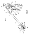
- Figure 1 illustrates a perspective view of a suture passing instrument according to a first embodiment of the present invention.
- Figure 2 illustrates an enlarged view of the distal end of the suture passing instrument of Figure 1 , with the two needles deployed.
- Figure 3 is a perspective view of the dual-needle actuator of the suture passing instrument of Figure 1 , with the two needles undeployed.
- Figure 4 illustrates a top view of the dual-needle actuator of Figure 3 .
- Figure 5 illustrates a side view of the dual-needle actuator of Figure 3 .
- Figure 6 illustrates an enlarged view of one of the two needles of the dual-needle actuator of Figure 3 .
- Figure 7 illustrates a perspective view of the handle assembly of the suture passing instrument of Figure 1 .
- Figure 8 illustrates an enlarged view of the needle of Figure 6 with pierced suture.
- Figure 9 illustrates an enlarged view of the distal end of a suture passing instrument according to a second embodiment of the present invention, with the two needles deployed.
- the present invention provides a suture passing instrument and technique for surgical repairs.
- the suture passing instrument comprises an elongated tubular member that houses two needles disposed in a side-by-side configuration.
- a dual-needle actuating structure communicates with the two needles.
- a handle assembly comprises a ratchet-like mechanism and a handle, the ratchet-like mechanism being pivotally connected to the handle.
- the ratchet-like mechanism articulates a jaw (coupled to the tip of the elongated tubular member) relative to the elongated tubular member.
- a suture is placed at the tip of the elongated tubular member.
- the jaw By actuating the ratchet-like mechanism, the jaw is articulated relative to the elongated tubular member thereby securing contact with the tissue.
- the dual-needle actuator pushes forward the two needles to capture the suture extending within the slot and advance it through the tissue to be sutured.
- Figures 1-9 illustrate various structural elements of suture passing instrument 100, 200 of the present invention provided with dual needles 55a, 55b ( Figure 2 ) and 155a, 155b ( Figure 9 ).
- suture passing instrument 100 comprises an elongated tubular member or shaft 12 having a longitudinal axis 12a, a proximal end 11, a distal end 13 and an axial throughbore therein (not shown).
- Elongated tubular member 12 may be a tube or a narrow-diameter rod of dimensions that permit the tubular member to be introduced through an associated cannula (for example, an 8.25 cannula) in a minimally invasive procedure, such as arthroscopic or other endoscopic procedures, or into a body cavity, such as the abdominal cavity.
- Elongated tubular member 12 connects a handle assembly 20 with a tip 10 consisting of a pair of jaws 10 comprising an upper jaw 10a and a lower jaw 10b.
- Lower jaw 10b is provided at the distal end 13 of the instrument and is preferably integral with the tubular member 12.
- Upper jaw 10a ( Figures 1 and 2 ) forms part of the tip 10 and may pivot with respect to the tip or lower jaw 10b.
- lower jaw 10b is substantially straight with respect to the shaft, while the upper jaw 10a is provided with a first (proximal) portion 102a (which, when the jaws are in the closed position, is about parallel to the lower jaw 10b and with the longitudinal axis 12a of the device) and with a second (distal) portion 101a (which, when the jaws are in the closed position, contacts a top surface of the most distal part of the lower jaw and forms an angle of about 30 to about 60 degrees (preferably of about 45 degrees) with the longitudinal axis 12a of the device).
- the second (distal) portion 101a may be provided with a plurality of teeth to enhance tissue grasping and suture stability.
- the lower jaw 10b of the suture passing instrument 100 includes a first (proximal) portion 102b (which is integral with the body of the instrument and is about parallel to the longitudinal axis 12a of the device) and with a second (distal) portion 101b which has a generally pyramidal configuration (when viewed in a perspective view).
- the second (distal) portion 101b may include a securing mechanism 16 which is formed integrally with the lower jaw and preferably includes two side longitudinal channels 16a (terminating in opening 16c (the end point of the tip)) and, optionally, a transversal suture loading slot 16b.
- the two side longitudinal channels 16a are configured to allow suture (or a strand of flexible material) to extend therethrough and to be securely positioned within two corresponding transversal slots or channels 15a, 15b (that extend at the most proximal part of the second (distal) portion 101b, and from a top surface to a lower surface of the lower jaw 10b).
- Slots 15a, 15b may have various configurations, for example, two lateral slots, grooves or wedges, each of the lateral slots, grooves or wedges being disposed on each end of the transversal slot, to allow increased suture positioning for future suture manipulation with the two needle construct of the invention.
- the strand of suture When disposed in the slots 15a, 15b, the strand of suture is placed with the ends of the suture being pulled through the two longitudinal side channels 16a so that the suture reaches the two transversal slots 15a, 15b and is also placed over the transversal suture loading slot 16b of the device.
- the suture When disposed in the slots 15a, 15b, the suture is securely in place for engagement by the needles 55a, 55b ( Figure 2 ) and 155a, 155b ( Figure 9 ).
- the suture is preferably a braided suture such as a FiberwireTM, sold by Arthrex, Inc., Naples, Florida.
- the two slots or channels 15a, 15b are also configured to allow needles 55a, 55b, 155a, 155b to extend therethrough in the side-by-side configuration illustrated in Figures 2 and 9 .
- Channels 15a, 15b are provided in a most distal end of lower jaw 10b, and, as noted, extend from a top (upper surface) of the lower jaw 10b to a bottom (lower surface) of the lower jaw 10b.
- the two slots 15a, 15b have the shape of a channel with a rectangular or square cross-section to allow the two needles 55a, 55b, 155a, 155b having a generally flat configuration to pass therethrough.
- the two openings 15a, 15b are angularly offset relative to a transversal axis 12b of the shaft 12, to allow the two needles 55a, 55b, 155a, 155b to exit and to form an angle of about 15 to about 30 degree with respect to the transversal axis and to diverge as they pass through tissue (i.e., the two needles 55a, 55b, 155a, 155b are not parallel to the transversal axis 12b of the shaft 12, when the needles are in the operative or deployed position).
- the two openings 15a, 15b are also angularly offset relative to the longitudinal axis 12a of the shaft 12, to allow the two needles 55a, 55b, 155a, 155b to exit and to form an angle of about 10 to about 60 degrees, preferably of about 45 degrees, relative to the longitudinal axis 12a.
- FIG. 3 illustrates dual-needle actuator 50 comprising dual shafts 52a, 52b positioned in a side-by-side configuration and terminating in dual needles 55a, 55b, 155a, 155b.
- Shafts 52a, 52b are slidingly received in the axial throughbore (channel) of the elongated tubular member 12.
- Dual needles 55a, 55b, 155a, 155b are substantially disposed within the channel of the shaft 12 when the needles are in a non-operative, or non-piercing, position. In an operative position, the two needles are advanced distally to exit openings 15a, 15b in the lower jaw 10b.
- the needles may be bendable, so that they can be moved generally with an axial force and can be bent on a curve, for example 45 degrees, to move generally toward the upper jaw 10a. It is to be expressly understood that the needles can be bent at any angle and advanced in any direction.
- each of the needles 55a, 55b has a pointed tip 60 at a distal end 61 of the needle and side barbs 66 provided from the pointed tip 60.
- the side barbs 66 are preferably about 2 mm from the pointed tip 60.
- the pointed tip 60 is designed to pierce the suture and the side barbs 66 are designed to carry the suture.
- each of the needles 55a, 55b has a generally flat, narrow and elongate configuration. Needles 55a, 55b may preferably be formed of nitinol or other suitable material.
- needles 155a, 155b also have a flat, elongated configuration terminating in pointed tip 60 (similar to the embodiment of Figures 2 and 6 ).
- needles 155a, 155b are not provided with side barbs, but rather with a hook 166 that securely engages and captures the suture strand but without piercing it.
- Dual-needle actuator 50 is provided within the shaft of the instrument and is designed to move the needles 55a, 55b, 155a, 155b in the lower jaw 10b, from a first position to a second position which is different from the first position.
- the needles 55a, 55b, 155a, 155b may be about parallel to the longitudinal axis 12a of the instrument (in the undeployed position or non-operative), while in the second position, the needles 55a, 55b, 155a, 155b may form an angle of about 10 to about 60 degrees with the longitudinal axis 12a of the instrument (in the deployed or operative position).
- needles 55a, 55b, 155a, 155b form an angle of about 45 degrees relative to the longitudinal axis 12a.
- needles 55a, 55b, 155a, 155b form an angle of about 15 to about 30 degree relative to each other (as shown in Figure 2 , i.e., in a non-parallel orientation with the transversal axis 12b).
- the dual-needle actuator 50 is actuated relative to the longitudinal axis 12a of the tubular member, and needles 55a, 55b, 155a, 155b are pushed forward toward openings 15a, 15b to exit these openings as shown in Figures 2 and 9 .
- the dual needle shafts 52a, 52b are machined side by side at about 15 to 30 degree angle, to allow the two needle points to diverge as they pass through the tissue to be sutured (for example, a tendon).
- Handle assembly 20 of the suturing instrument 100, 200, illustrated in Figures 1 and 7 is provided at the proximal end 11 of the instrument and includes a ratchet-like mechanism 22 and a handle 28, the ratchet-like mechanism 22 being pivotally connected to the handle 28.
- the ratchet-like mechanism 22 consists of a finger lever 22a with a ratchet 22b, and a releaser 22c with a hook 22d, the ratchet 22b and the hook 22d having a plurality of teeth to engage the finger lever 22a and the releaser 22c.
- the finger lever 22a and the releaser 22c perform substantially similar to a ratchet and a pawl.
- the finger lever 22a and the releaser 22c are pivotally connected to the distal end of the handle (not shown).
- the proximal and distal ends of the handle 28 (not shown) are linkably connected via a link 28a and tension between the proximal and distal ends may be additionally maintained using springs 28b (shown in Figure 7 only).
- the finger lever 22a is designed to move from a first position to a second position, with a spring 22a' provided to maintain tension on the finger lever 22a and to force the finger lever 22a to go back to a default position. At its default position, the finger lever 22a is farthest from the distal end of the handle 28.
- the releaser 22c is designed to move from a first position to a second position, with a spring 22c' provided to maintain tension on the releaser 22c and to force the releaser 22c to go back to a default position.
- the releaser 22c further includes a portion designed to engage into a cross pin (not shown) and to securely hold the releaser 22c.
- the suture passing instrument 100, 200 further includes an actuator 19, which is provided within the shaft 12 and at the distal end of the shaft.
- a proximal end of the actuator 19 is pivotally connected to the finger lever 22a and a distal end of the actuator 19 is pivotally connected to the upper jaw 10a.
- the actuator 19 is designed to move the upper jaw 10a from a first position to a second position as the finger lever 22a is moved from a first position to a second position. At the default position of the finger lever 22a, the upper jaw 10a is farthest from the lower jaw 10b.
- a surgeon may seize and maintain tissue with jaws 10a, 10b.
- the two needles 55a, 55b, 155a, 155b are advanced to capture the suture strand positioned within securing mechanism 16, and to further carry and advance the captured suture strand through the tissue to be sutured.
- a method of employing the suture passing instrument 100 of the present invention begins by loading the two needles 55a, 55b, 155a, 155b into the cannulation on the proximal end of the shaft 12 of the suture passing instrument 100, 200.
- the slot 54a ( Figure 5 ) on the proximal end of the dual-needle actuator 50 is engaged securely into a cross pin on the proximal end of handle 28 of the suture passing instrument.
- the needles facilitate passing the suture 80 ( Figure 8 ) through the tissue.
- Suture 80 is loaded into the slots on the lower jaw 10b of the suture passing instrument 100, 200.
- the finger lever 22a on the suture passing instrument 100, 200 By actuating the finger lever 22a on the suture passing instrument 100, 200, the upper jaw 10a and the lower jaw 10b are brought together (in a closed position), and the suture passing instrument 100 is advanced into the proximity of tissue to be sutured (for example, a joint such as the subacromial space).
- the two jaws may be held together (in the closed position) by actuating the releaser 22c (from an "Unlock" position to a "Lock” position).
- the upper jaw 10a is then disengaged from the lower jaw 10b by releasing the finger lever 22a and a desired bite of tissue is grasped.
- the proximal and distal members of the handle 28 of the handle assembly 20 are squeezed together so that the two needles 55a, 55b, 155a, 155b are advanced distally, exiting the openings 15a, 15b on the lower jaw 10b.
- the pointed tips 60 of the needles 55a, 55b then pierce partly or completely through the suture 80 ( Figure 8 ) and the needles carry the suture.
- needles 155a, 155b do not pierce suture 80 but rather captures it in the two lateral slots or hooks 166 ( Figure 9 ).
- the needles and the suture are advanced distally using the handle assembly to advance the suture 80 through the tissue.
- the suture is captured and advanced by the two diverging needles 55a, 55b, 155a, 155b through the soft tissue.
- the suture 80 may be retrieved with a suture retriever or tissue grasper.
- the suture passing instrument 100, 200 of the present invention may be employed in various surgical medical procedures for advancing the suture in the proximity of a surgical site, and for employing the suture with a cannulated instrument during such surgical procedures.
- the suture passing instrument may be employed in endoscopic procedures.
- the suture passing instrument may be utilized in other general surgical and specialty procedures that require suturing at a remote site, such as inside the body.
- the suture passing instrument of the present invention may be also used in repairs where suture visibility or finger access can be limited.
- suture passing instrument may be particularly useful for performing remote procedures through access sheaths, trocars and cannulated surgical instruments, it will also find use in open surgical procedures.
- a method of suturing tissue using the dual-needle suture passing instrument 100, 200 of the present invention comprises the steps of: (i) providing a dual-needle passing instrument 100 in the proximity of anatomical tissue to be sutured; (ii) positioning a flexible strand within a tip of the dual-needle passing instrument; (iii) engaging the suture with at least one of the two needles passing through the lower jaw of the instrument and exiting the lower jaw in a diverging orientation; and (iv) retrieving the suture.
- a method of suturing a tissue using the dual-needle suture passing instrument 100, 200 of the present invention comprises the steps of: (i) loading two needles onto the instrument; (ii) loading a suture into the tip of the instrument; (iii) opening the jaws by releasing a finger lever and grasping the desired portion of tissue; (iv) closing the jaws using the finger lever and advancing the two needles (with suture engaged and captured thereon) through the tissue; (v) retracting the two needles; (vi) and retrieving the suture using a retriever or grasper.
Abstract
Description
- The present invention relates to the field of surgery and, more particularly, to a suture passing instrument with a dual-needle construct.
- Both open and endoscopic surgical procedures often require sutures to ligate, join or otherwise treat tissue. Generally, suture needles with attached suture strands are grasped either manually or by forceps and passed through the desired work site so a knot can be tied. While the procedures are fairly uncomplicated in open surgery where most suture sites are readily accessible, in endoscopic procedures, where access to the work site is not readily available, the surgeon must use auxiliary devices to be able to grasp the suture strands and pass them through desired tissue.
- Although various instruments have been developed for surgical repairs requiring the passing of sutures to distant locations, instruments that allow a surgeon to quickly, accurately, and easily pass a suture through soft tissue are still needed.
- The present invention provides a suture passing instrument for endoscopic surgical repairs. The suture passing instrument comprises an elongated tubular member that houses two needles disposed in a side-by-side configuration. A dual-needle actuator communicates with the two needles. A suture is placed in a securing mechanism at the tip of the lower jaw. By advancing the dual-needle actuator relative to the body of the instrument, the two needles are pushed forward to capture the suture and advance it through the tissue to be sutured.
- Other features and advantages of the present invention will become apparent from the following description of the invention which refers to the accompanying drawings.
-
Figure 1 illustrates a perspective view of a suture passing instrument according to a first embodiment of the present invention. -
Figure 2 illustrates an enlarged view of the distal end of the suture passing instrument ofFigure 1 , with the two needles deployed. -
Figure 3 is a perspective view of the dual-needle actuator of the suture passing instrument ofFigure 1 , with the two needles undeployed. -
Figure 4 illustrates a top view of the dual-needle actuator ofFigure 3 . -
Figure 5 illustrates a side view of the dual-needle actuator ofFigure 3 . -
Figure 6 illustrates an enlarged view of one of the two needles of the dual-needle actuator ofFigure 3 . -
Figure 7 illustrates a perspective view of the handle assembly of the suture passing instrument ofFigure 1 . -
Figure 8 illustrates an enlarged view of the needle ofFigure 6 with pierced suture. -
Figure 9 illustrates an enlarged view of the distal end of a suture passing instrument according to a second embodiment of the present invention, with the two needles deployed. - The present invention provides a suture passing instrument and technique for surgical repairs. The suture passing instrument comprises an elongated tubular member that houses two needles disposed in a side-by-side configuration. A dual-needle actuating structure communicates with the two needles. A handle assembly comprises a ratchet-like mechanism and a handle, the ratchet-like mechanism being pivotally connected to the handle. The ratchet-like mechanism articulates a jaw (coupled to the tip of the elongated tubular member) relative to the elongated tubular member. A suture is placed at the tip of the elongated tubular member. By actuating the ratchet-like mechanism, the jaw is articulated relative to the elongated tubular member thereby securing contact with the tissue. By actuating the handle of the handle assembly, the dual-needle actuator pushes forward the two needles to capture the suture extending within the slot and advance it through the tissue to be sutured.
- Referring now to the drawings, where like elements are designated by like reference numerals,
Figures 1-9 illustrate various structural elements ofsuture passing instrument dual needles Figure 2 ) and 155a, 155b (Figure 9 ). - As shown in
Figure 1 , suturepassing instrument 100 comprises an elongated tubular member orshaft 12 having a longitudinal axis 12a, aproximal end 11, adistal end 13 and an axial throughbore therein (not shown). Elongatedtubular member 12 may be a tube or a narrow-diameter rod of dimensions that permit the tubular member to be introduced through an associated cannula (for example, an 8.25 cannula) in a minimally invasive procedure, such as arthroscopic or other endoscopic procedures, or into a body cavity, such as the abdominal cavity. - Elongated
tubular member 12 connects ahandle assembly 20 with atip 10 consisting of a pair ofjaws 10 comprising anupper jaw 10a and alower jaw 10b.Lower jaw 10b is provided at thedistal end 13 of the instrument and is preferably integral with thetubular member 12.Upper jaw 10a (Figures 1 and2 ) forms part of thetip 10 and may pivot with respect to the tip orlower jaw 10b. As illustrated inFigure 1 ,lower jaw 10b is substantially straight with respect to the shaft, while theupper jaw 10a is provided with a first (proximal)portion 102a (which, when the jaws are in the closed position, is about parallel to thelower jaw 10b and with the longitudinal axis 12a of the device) and with a second (distal)portion 101a (which, when the jaws are in the closed position, contacts a top surface of the most distal part of the lower jaw and forms an angle of about 30 to about 60 degrees (preferably of about 45 degrees) with the longitudinal axis 12a of the device). The second (distal)portion 101a may be provided with a plurality of teeth to enhance tissue grasping and suture stability. - The
lower jaw 10b of thesuture passing instrument 100 includes a first (proximal)portion 102b (which is integral with the body of the instrument and is about parallel to the longitudinal axis 12a of the device) and with a second (distal)portion 101b which has a generally pyramidal configuration (when viewed in a perspective view). - The second (distal)
portion 101b may include asecuring mechanism 16 which is formed integrally with the lower jaw and preferably includes two sidelongitudinal channels 16a (terminating in opening 16c (the end point of the tip)) and, optionally, a transversalsuture loading slot 16b. The two sidelongitudinal channels 16a are configured to allow suture (or a strand of flexible material) to extend therethrough and to be securely positioned within two corresponding transversal slots orchannels portion 101b, and from a top surface to a lower surface of thelower jaw 10b).Slots - When disposed in the
slots longitudinal side channels 16a so that the suture reaches the twotransversal slots suture loading slot 16b of the device. When disposed in theslots needles Figure 2 ) and 155a, 155b (Figure 9 ). The suture is preferably a braided suture such as a Fiberwire™, sold by Arthrex, Inc., Naples, Florida. - The two slots or
channels needles Figures 2 and9 .Channels lower jaw 10b, and, as noted, extend from a top (upper surface) of thelower jaw 10b to a bottom (lower surface) of thelower jaw 10b. Preferably, the twoslots needles - Preferably, and as shown in
Figures 2 and9 , the twoopenings shaft 12, to allow the twoneedles needles shaft 12, when the needles are in the operative or deployed position). The twoopenings shaft 12, to allow the twoneedles -
Figure 3 illustrates dual-needle actuator 50 comprisingdual shafts dual needles tubular member 12.Dual needles shaft 12 when the needles are in a non-operative, or non-piercing, position. In an operative position, the two needles are advanced distally to exitopenings lower jaw 10b. The needles may be bendable, so that they can be moved generally with an axial force and can be bent on a curve, for example 45 degrees, to move generally toward theupper jaw 10a. It is to be expressly understood that the needles can be bent at any angle and advanced in any direction. - As illustrated in
Figures 2 and6 , each of theneedles pointed tip 60 at adistal end 61 of the needle andside barbs 66 provided from thepointed tip 60. Theside barbs 66 are preferably about 2 mm from thepointed tip 60. Thepointed tip 60 is designed to pierce the suture and theside barbs 66 are designed to carry the suture. Preferably, each of theneedles Needles - In an alternative embodiment illustrated in
Figure 9 ,needles 155a, 155b also have a flat, elongated configuration terminating in pointed tip 60 (similar to the embodiment ofFigures 2 and6 ). However,needles 155a, 155b are not provided with side barbs, but rather with ahook 166 that securely engages and captures the suture strand but without piercing it. - Dual-
needle actuator 50 is provided within the shaft of the instrument and is designed to move theneedles lower jaw 10b, from a first position to a second position which is different from the first position. In the first position, theneedles needles Figure 2 , i.e., in a non-parallel orientation with the transversal axis 12b). - In use, the dual-
needle actuator 50 is actuated relative to the longitudinal axis 12a of the tubular member, andneedles openings Figures 2 and9 . Preferably, thedual needle shafts - Handle
assembly 20 of thesuturing instrument Figures 1 and7 , is provided at theproximal end 11 of the instrument and includes a ratchet-like mechanism 22 and ahandle 28, the ratchet-like mechanism 22 being pivotally connected to thehandle 28. The ratchet-like mechanism 22 consists of afinger lever 22a with aratchet 22b, and areleaser 22c with ahook 22d, theratchet 22b and thehook 22d having a plurality of teeth to engage thefinger lever 22a and thereleaser 22c. Thefinger lever 22a and thereleaser 22c perform substantially similar to a ratchet and a pawl. Thefinger lever 22a and thereleaser 22c are pivotally connected to the distal end of the handle (not shown). The proximal and distal ends of the handle 28 (not shown) are linkably connected via alink 28a and tension between the proximal and distal ends may be additionally maintained usingsprings 28b (shown inFigure 7 only). - The
finger lever 22a is designed to move from a first position to a second position, with aspring 22a' provided to maintain tension on thefinger lever 22a and to force thefinger lever 22a to go back to a default position. At its default position, thefinger lever 22a is farthest from the distal end of thehandle 28. - The
releaser 22c is designed to move from a first position to a second position, with aspring 22c' provided to maintain tension on thereleaser 22c and to force thereleaser 22c to go back to a default position. Thereleaser 22c further includes a portion designed to engage into a cross pin (not shown) and to securely hold thereleaser 22c. - The
suture passing instrument actuator 19, which is provided within theshaft 12 and at the distal end of the shaft. A proximal end of theactuator 19 is pivotally connected to thefinger lever 22a and a distal end of theactuator 19 is pivotally connected to theupper jaw 10a. Theactuator 19 is designed to move theupper jaw 10a from a first position to a second position as thefinger lever 22a is moved from a first position to a second position. At the default position of thefinger lever 22a, theupper jaw 10a is farthest from thelower jaw 10b. - With
hand mechanism 20, a surgeon may seize and maintain tissue withjaws pusher 54 of dual-needle actuator 50, the twoneedles mechanism 16, and to further carry and advance the captured suture strand through the tissue to be sutured. - A method of employing the
suture passing instrument 100 of the present invention begins by loading the twoneedles shaft 12 of thesuture passing instrument slot 54a (Figure 5 ) on the proximal end of the dual-needle actuator 50 is engaged securely into a cross pin on the proximal end ofhandle 28 of the suture passing instrument. The needles facilitate passing the suture 80 (Figure 8 ) through the tissue. -
Suture 80 is loaded into the slots on thelower jaw 10b of thesuture passing instrument finger lever 22a on thesuture passing instrument upper jaw 10a and thelower jaw 10b are brought together (in a closed position), and thesuture passing instrument 100 is advanced into the proximity of tissue to be sutured (for example, a joint such as the subacromial space). The two jaws may be held together (in the closed position) by actuating thereleaser 22c (from an "Unlock" position to a "Lock" position). Theupper jaw 10a is then disengaged from thelower jaw 10b by releasing thefinger lever 22a and a desired bite of tissue is grasped. - With the jaws closed around the tissue (and preferably with the
releaser 22c in the "Lock" position), the proximal and distal members of thehandle 28 of thehandle assembly 20 are squeezed together so that the twoneedles openings lower jaw 10b. The pointedtips 60 of theneedles Figure 8 ) and the needles carry the suture. Alternatively, needles 155a, 155b do not piercesuture 80 but rather captures it in the two lateral slots or hooks 166 (Figure 9 ). The needles and the suture are advanced distally using the handle assembly to advance thesuture 80 through the tissue. The suture is captured and advanced by the two divergingneedles suture 80 may be retrieved with a suture retriever or tissue grasper. - The
suture passing instrument Figures 1-9 , may be employed in various surgical medical procedures for advancing the suture in the proximity of a surgical site, and for employing the suture with a cannulated instrument during such surgical procedures. For example, the suture passing instrument may be employed in endoscopic procedures. Additionally, the suture passing instrument may be utilized in other general surgical and specialty procedures that require suturing at a remote site, such as inside the body. The suture passing instrument of the present invention may be also used in repairs where suture visibility or finger access can be limited. - It will be appreciated, of course, that while the suture passing instrument may be particularly useful for performing remote procedures through access sheaths, trocars and cannulated surgical instruments, it will also find use in open surgical procedures.
- In an exemplary and illustrative embodiment only, a method of suturing tissue using the dual-needle
suture passing instrument needle passing instrument 100 in the proximity of anatomical tissue to be sutured; (ii) positioning a flexible strand within a tip of the dual-needle passing instrument; (iii) engaging the suture with at least one of the two needles passing through the lower jaw of the instrument and exiting the lower jaw in a diverging orientation; and (iv) retrieving the suture. - According to another exemplary and illustrative embodiment only, a method of suturing a tissue using the dual-needle
suture passing instrument - Although the present invention has been described in connection with preferred embodiments, many modifications and variations will become apparent to those skilled in the art. While preferred embodiments of the invention have been described and illustrated above, it should be understood that these are exemplary of the invention and are not to be considered as limiting. Accordingly, it is not intended that the present invention be limited to the illustrated embodiments, but only by the appended claims.
Claims (11)
- A suture passing instrument comprising:a shaft having a longitudinal axis, a transversal axis, a distal end and a proximal end;a first jaw member integral to the distal end of the shaft, the first jaw member having at least one passage configured to receive two needles and comprising a securing mechanism for securing a suture;a second jaw member mounted to the distal end of the shaft and pivotally connected to the first jaw member such that the second jaw member is moveable with respect to the first jaw member; anda handle assembly configured to move the two needles from a first position to a second position, and to move the second jaw member with respect to the first jaw member.
- The suture passing instrument of claim 1, wherein the securing mechanism comprises two slots at a distal end of the first jaw member, each of the two slots being positioned on sides of the distal end, to allow the needles and the suture to pass therethrough.
- The suture passing instrument of claim 1, wherein the two needles are provided in a side-by-side configuration.
- The suture passing instrument of claim 1, wherein, in the first position, the two needles are about parallel to the longitudinal axis of the instrument.
- The suture passing instrument of claim 1, wherein, in the second position, the two needles are non-parallel to the longitudinal axis of the instrument.
- The suture passing instrument of claim 5, wherein, in the second position, the two needles form an angle of about 10 about 60 degrees relative to the longitudinal axis of the instrument.
- The suture passing instrument of claim 5, wherein, in the second position, the two needles form an angle of about 15 about 30 relative to the transversal axis of the shaft.
- The suture passing instrument of claim 1, wherein the handle assembly comprises a handle and a ratchet-like mechanism, wherein the handle comprises a proximal member and a distal member, and wherein the ratchet-like mechanism comprises a finger lever with a ratchet and a releaser with a hook, the finger lever and the releaser being pivotally connected to the distal member of the handle.
- The suture passing instrument of claim 1, wherein the two needles have a flat elongated configuration.
- The suture passing instrument of claim 1, wherein each of the two needles is provided with a sharp tip and a hook.
- The suture passing instrument of claim 1, wherein each of the two needles is provided with a sharp tip and side barbs.
Applications Claiming Priority (1)
| Application Number | Priority Date | Filing Date | Title |
|---|---|---|---|
| US96827707P | 2007-08-27 | 2007-08-27 |
Publications (1)
| Publication Number | Publication Date |
|---|---|
| EP2030575A1 true EP2030575A1 (en) | 2009-03-04 |
Family
ID=40205644
Family Applications (1)
| Application Number | Title | Priority Date | Filing Date |
|---|---|---|---|
| EP08162994A Withdrawn EP2030575A1 (en) | 2007-08-27 | 2008-08-26 | Suturing instrument with dual needles |
Country Status (2)
| Country | Link |
|---|---|
| US (1) | US8663250B2 (en) |
| EP (1) | EP2030575A1 (en) |
Cited By (12)
| Publication number | Priority date | Publication date | Assignee | Title |
|---|---|---|---|---|
| CN104939875A (en) * | 2013-12-16 | 2015-09-30 | 赛特里克斯整形公司 | Automatically reloading suture passer devices and methods |
| US10143464B2 (en) | 2013-09-23 | 2018-12-04 | Ceterix Orthopaedics, Inc. | Arthroscopic knot pusher and suture cutter |
| US10188382B2 (en) | 2011-05-06 | 2019-01-29 | Ceterix Orthopaedics, Inc. | Suture passer devices and methods |
| US10226245B2 (en) | 2015-07-21 | 2019-03-12 | Ceterix Orthopaedics, Inc. | Automatically reloading suture passer devices that prevent entanglement |
| US10405853B2 (en) | 2015-10-02 | 2019-09-10 | Ceterix Orthpaedics, Inc. | Knot tying accessory |
| US10441273B2 (en) | 2007-07-03 | 2019-10-15 | Ceterix Orthopaedics, Inc. | Pre-tied surgical knots for use with suture passers |
| US10524778B2 (en) | 2011-09-28 | 2020-01-07 | Ceterix Orthopaedics | Suture passers adapted for use in constrained regions |
| US10537321B2 (en) | 2014-04-08 | 2020-01-21 | Ceterix Orthopaedics, Inc. | Suture passers adapted for use in constrained regions |
| US10561410B2 (en) | 2011-01-10 | 2020-02-18 | Ceterix Orthopaedics, Inc. | Transosteal anchoring methods for tissue repair |
| US10758222B2 (en) | 2011-05-06 | 2020-09-01 | Ceterix Orthopaedics, Inc. | Meniscus repair |
| US10987095B2 (en) | 2011-01-10 | 2021-04-27 | Ceterix Orthopaedics, Inc. | Suture methods for forming locking loops stitches |
| US11744575B2 (en) | 2009-11-09 | 2023-09-05 | Ceterix Orthopaedics, Inc. | Suture passer devices and methods |
Families Citing this family (48)
| Publication number | Priority date | Publication date | Assignee | Title |
|---|---|---|---|---|
| EP2314257B9 (en) | 2000-05-01 | 2013-02-27 | ArthroSurface, Inc. | System for joint resurface repair |
| US6610067B2 (en) | 2000-05-01 | 2003-08-26 | Arthrosurface, Incorporated | System and method for joint resurface repair |
| US8177841B2 (en) | 2000-05-01 | 2012-05-15 | Arthrosurface Inc. | System and method for joint resurface repair |
| US8388624B2 (en) | 2003-02-24 | 2013-03-05 | Arthrosurface Incorporated | Trochlear resurfacing system and method |
| EP1845890A4 (en) | 2003-11-20 | 2010-06-09 | Arthrosurface Inc | System and method for retrograde procedure |
| EP1765201A4 (en) | 2004-06-28 | 2013-01-23 | Arthrosurface Inc | System for articular surface replacement |
| US7828853B2 (en) | 2004-11-22 | 2010-11-09 | Arthrosurface, Inc. | Articular surface implant and delivery system |
| AU2007332787A1 (en) | 2006-12-11 | 2008-06-19 | Arthrosurface Incorporated | Retrograde resection apparatus and method |
| US8500809B2 (en) | 2011-01-10 | 2013-08-06 | Ceterix Orthopaedics, Inc. | Implant and method for repair of the anterior cruciate ligament |
| US20100130990A1 (en) * | 2007-07-03 | 2010-05-27 | Saliman Justin D | Methods of suturing and repairing tissue using a continuous suture passer device |
| US9314234B2 (en) | 2007-07-03 | 2016-04-19 | Ceterix Orthopaedics, Inc. | Pre-tied surgical knots for use with suture passers |
| US8663253B2 (en) | 2007-07-03 | 2014-03-04 | Ceterix Orthopaedics, Inc. | Methods of meniscus repair |
| US8911456B2 (en) | 2007-07-03 | 2014-12-16 | Ceterix Orthopaedics, Inc. | Methods and devices for preventing tissue bridging while suturing |
| US9211119B2 (en) | 2007-07-03 | 2015-12-15 | Ceterix Orthopaedics, Inc. | Suture passers and methods of passing suture |
| US8702731B2 (en) | 2007-07-03 | 2014-04-22 | Ceterix Orthopaedics, Inc. | Suturing and repairing tissue using in vivo suture loading |
| EP2211725A4 (en) * | 2007-11-05 | 2015-04-01 | Ceterix Orthopedics Inc | Suture passing instrument and method |
| EP2262448A4 (en) | 2008-03-03 | 2014-03-26 | Arthrosurface Inc | Bone resurfacing system and method |
| EP2184015B1 (en) | 2008-11-07 | 2019-12-25 | Arthrex, Inc. | Suturing instrument for passing multiple sutures |
| CA3064646C (en) | 2009-04-17 | 2023-01-03 | Arthrosurface Incorporated | Glenoid resurfacing system and method |
| US10945743B2 (en) | 2009-04-17 | 2021-03-16 | Arthrosurface Incorporated | Glenoid repair system and methods of use thereof |
| US9662126B2 (en) | 2009-04-17 | 2017-05-30 | Arthrosurface Incorporated | Glenoid resurfacing system and method |
| US20110040322A1 (en) * | 2009-07-27 | 2011-02-17 | Tracey Stribling | Device & method for the positioning of tissue during laparoscopic or endoscopic surgery |
| US9011454B2 (en) | 2009-11-09 | 2015-04-21 | Ceterix Orthopaedics, Inc. | Suture passer with radiused upper jaw |
| JP5719374B2 (en) * | 2009-11-09 | 2015-05-20 | セテリックス オーソピーディクス インコーポレイテッド | Device, system, and method for repairing a meniscus |
| BR112012022482A2 (en) | 2010-03-05 | 2016-07-19 | Arthrosurface Inc | tibial surface recomposition system and method. |
| AU2012225668A1 (en) * | 2011-03-07 | 2013-10-10 | Passer Stitch, Llc | Suture passing devices and methods |
| US9066716B2 (en) | 2011-03-30 | 2015-06-30 | Arthrosurface Incorporated | Suture coil and suture sheath for tissue repair |
| US8882834B2 (en) | 2011-07-08 | 2014-11-11 | Smith & Nephew, Inc. | Soft tissue repair |
| US8801727B2 (en) | 2011-07-08 | 2014-08-12 | Smith & Nephew, Inc. | Orthopedic suture passer and method |
| US8888849B2 (en) | 2011-07-08 | 2014-11-18 | Smith & Nephew, Inc. | Soft tissue repair |
| US9662105B2 (en) | 2011-07-08 | 2017-05-30 | Smith & Nephew, Inc. | Suture passer and method |
| US8951263B2 (en) | 2011-07-08 | 2015-02-10 | Smith & Nephew, Inc. | Orthopedic suture passer and method |
| US9357997B2 (en) | 2011-07-08 | 2016-06-07 | Smith & Nephew, Inc. | Suture passer and method |
| DE102011107178A1 (en) * | 2011-07-13 | 2013-01-17 | Karl Storz Gmbh & Co. Kg | Medical cutting instrument for cutting muscles and tendons |
| US20130165982A1 (en) | 2011-12-22 | 2013-06-27 | Arthrosurface Incorporated | System and Method for Bone Fixation |
| DE112013003358T5 (en) | 2012-07-03 | 2015-03-19 | Arthrosurface, Inc. | System and procedure for joint surface replacement and repair |
| US20140243850A1 (en) * | 2013-02-28 | 2014-08-28 | Intuitive Surgical Operations, Inc. | Surgical instrument with curved jaws for surgical system |
| US9492200B2 (en) | 2013-04-16 | 2016-11-15 | Arthrosurface Incorporated | Suture system and method |
| US11607319B2 (en) | 2014-03-07 | 2023-03-21 | Arthrosurface Incorporated | System and method for repairing articular surfaces |
| US9861492B2 (en) | 2014-03-07 | 2018-01-09 | Arthrosurface Incorporated | Anchor for an implant assembly |
| US10624748B2 (en) | 2014-03-07 | 2020-04-21 | Arthrosurface Incorporated | System and method for repairing articular surfaces |
| US10188381B2 (en) | 2015-11-20 | 2019-01-29 | Dura Tap Llc | Suture repair device |
| US9439647B1 (en) | 2016-03-02 | 2016-09-13 | Arthrogenx, LLC. | Suture passing instruments and methods |
| US10441272B2 (en) | 2017-06-29 | 2019-10-15 | Medos International Sarl | Suture magazine for suture passing surgical device |
| CA3108761A1 (en) | 2017-08-04 | 2019-02-07 | Arthrosurface Incorporated | Multicomponent articular surface implant |
| US20190133573A1 (en) * | 2017-11-03 | 2019-05-09 | Dura Tap Llc | Suturing kit |
| US10076322B1 (en) | 2018-01-11 | 2018-09-18 | Arthrex, Inc. | Tissue button |
| WO2020186099A1 (en) | 2019-03-12 | 2020-09-17 | Arthrosurface Incorporated | Humeral and glenoid articular surface implant systems and methods |
Citations (6)
| Publication number | Priority date | Publication date | Assignee | Title |
|---|---|---|---|---|
| US20020147456A1 (en) | 2001-02-26 | 2002-10-10 | Diduch David R. | Superelastic suture passing devices and methods |
| US6533795B1 (en) | 2000-04-11 | 2003-03-18 | Opus Medical, Inc | Dual function suturing apparatus and method |
| US6770084B1 (en) | 2002-06-26 | 2004-08-03 | Opus Medical, Inc. | Suture capture device |
| EP1498075A1 (en) * | 2003-06-23 | 2005-01-19 | Ethicon, Inc. | Tissue grasper/suture passer instrument |
| US20060020162A1 (en) | 2004-06-18 | 2006-01-26 | Ablatrics, Inc. | Methods and system for tissue cavity closure |
| EP1958574A1 (en) * | 2007-02-13 | 2008-08-20 | Arthrex, Inc. | Suture passing instrument |
Family Cites Families (6)
| Publication number | Priority date | Publication date | Assignee | Title |
|---|---|---|---|---|
| US4957498A (en) * | 1987-11-05 | 1990-09-18 | Concept, Inc. | Suturing instrument |
| US7112208B2 (en) * | 2001-08-06 | 2006-09-26 | Morris John K | Compact suture punch with malleable needle |
| JP4489428B2 (en) * | 2001-10-01 | 2010-06-23 | サージカル ソリューションズ リミテッド ライアビリティ カンパニー | Suture device |
| US7879046B2 (en) * | 2001-10-01 | 2011-02-01 | Depuy Mitek, Inc. | Suturing apparatus and method |
| EP1306056B1 (en) * | 2001-10-23 | 2006-05-24 | Arthrex, Inc. | Tissue suturing instrument |
| US7585305B2 (en) * | 2002-05-15 | 2009-09-08 | Arthrex, Inc. | Suture passing instrument |
-
2008
- 2008-08-26 EP EP08162994A patent/EP2030575A1/en not_active Withdrawn
- 2008-08-26 US US12/198,798 patent/US8663250B2/en active Active
Patent Citations (6)
| Publication number | Priority date | Publication date | Assignee | Title |
|---|---|---|---|---|
| US6533795B1 (en) | 2000-04-11 | 2003-03-18 | Opus Medical, Inc | Dual function suturing apparatus and method |
| US20020147456A1 (en) | 2001-02-26 | 2002-10-10 | Diduch David R. | Superelastic suture passing devices and methods |
| US6770084B1 (en) | 2002-06-26 | 2004-08-03 | Opus Medical, Inc. | Suture capture device |
| EP1498075A1 (en) * | 2003-06-23 | 2005-01-19 | Ethicon, Inc. | Tissue grasper/suture passer instrument |
| US20060020162A1 (en) | 2004-06-18 | 2006-01-26 | Ablatrics, Inc. | Methods and system for tissue cavity closure |
| EP1958574A1 (en) * | 2007-02-13 | 2008-08-20 | Arthrex, Inc. | Suture passing instrument |
Cited By (16)
| Publication number | Priority date | Publication date | Assignee | Title |
|---|---|---|---|---|
| US10441273B2 (en) | 2007-07-03 | 2019-10-15 | Ceterix Orthopaedics, Inc. | Pre-tied surgical knots for use with suture passers |
| US11744575B2 (en) | 2009-11-09 | 2023-09-05 | Ceterix Orthopaedics, Inc. | Suture passer devices and methods |
| US10561410B2 (en) | 2011-01-10 | 2020-02-18 | Ceterix Orthopaedics, Inc. | Transosteal anchoring methods for tissue repair |
| US10987095B2 (en) | 2011-01-10 | 2021-04-27 | Ceterix Orthopaedics, Inc. | Suture methods for forming locking loops stitches |
| US10188382B2 (en) | 2011-05-06 | 2019-01-29 | Ceterix Orthopaedics, Inc. | Suture passer devices and methods |
| US10758222B2 (en) | 2011-05-06 | 2020-09-01 | Ceterix Orthopaedics, Inc. | Meniscus repair |
| US10524778B2 (en) | 2011-09-28 | 2020-01-07 | Ceterix Orthopaedics | Suture passers adapted for use in constrained regions |
| US10143464B2 (en) | 2013-09-23 | 2018-12-04 | Ceterix Orthopaedics, Inc. | Arthroscopic knot pusher and suture cutter |
| US10820899B2 (en) | 2013-09-23 | 2020-11-03 | Ceterix Orthopaedics, Inc. | Arthroscopic knot pusher and suture cutter |
| US10524779B2 (en) | 2013-12-16 | 2020-01-07 | Ceterix Orthopaedics, Inc. | Automatically reloading suture passer devices and methods |
| CN104939875A (en) * | 2013-12-16 | 2015-09-30 | 赛特里克斯整形公司 | Automatically reloading suture passer devices and methods |
| CN104939875B (en) * | 2013-12-16 | 2019-07-26 | 赛特里克斯整形公司 | Automatically suture passer device and method are reloaded |
| US10537321B2 (en) | 2014-04-08 | 2020-01-21 | Ceterix Orthopaedics, Inc. | Suture passers adapted for use in constrained regions |
| US10806442B2 (en) | 2015-07-21 | 2020-10-20 | Ceterix Orthopaedics, Inc. | Automatically reloading suture passer devices that prevent entanglement |
| US10226245B2 (en) | 2015-07-21 | 2019-03-12 | Ceterix Orthopaedics, Inc. | Automatically reloading suture passer devices that prevent entanglement |
| US10405853B2 (en) | 2015-10-02 | 2019-09-10 | Ceterix Orthpaedics, Inc. | Knot tying accessory |
Also Published As
| Publication number | Publication date |
|---|---|
| US8663250B2 (en) | 2014-03-04 |
| US20090062816A1 (en) | 2009-03-05 |
Similar Documents
| Publication | Publication Date | Title |
|---|---|---|
| US8663250B2 (en) | Suturing instrument with dual needles and method of passing suture | |
| EP2033583B1 (en) | In-line suture passer | |
| US9393010B2 (en) | Suturing instrument for passing multiple sutures | |
| US11202623B2 (en) | Suture passer | |
| US7972344B2 (en) | Suture passing instrument and method of passing suture | |
| US9610075B2 (en) | Suture passing devices and methods | |
| US7585305B2 (en) | Suture passing instrument | |
| US9358001B2 (en) | Advance suture passer | |
| US7879048B2 (en) | Suture capture device | |
| US10058325B2 (en) | Suture passer and method of tissue repair | |
| US8092489B2 (en) | Tissue grasping apparatus | |
| US10792035B2 (en) | Combined tissue grasper-suture retriever instrument and method of tissue repair | |
| EP2238919A2 (en) | Endoscopic apparatus for manipulating tissue | |
| EP1538992A1 (en) | Suture capture device |
Legal Events
| Date | Code | Title | Description |
|---|---|---|---|
| PUAI | Public reference made under article 153(3) epc to a published international application that has entered the european phase |
Free format text: ORIGINAL CODE: 0009012 |
|
| AK | Designated contracting states |
Kind code of ref document: A1 Designated state(s): AT BE BG CH CY CZ DE DK EE ES FI FR GB GR HR HU IE IS IT LI LT LU LV MC MT NL NO PL PT RO SE SI SK TR |
|
| AX | Request for extension of the european patent |
Extension state: AL BA MK RS |
|
| 17P | Request for examination filed |
Effective date: 20090702 |
|
| 17Q | First examination report despatched |
Effective date: 20090806 |
|
| AKX | Designation fees paid |
Designated state(s): AT DE FR GB IT |
|
| GRAP | Despatch of communication of intention to grant a patent |
Free format text: ORIGINAL CODE: EPIDOSNIGR1 |
|
| INTG | Intention to grant announced |
Effective date: 20140519 |
|
| GRAS | Grant fee paid |
Free format text: ORIGINAL CODE: EPIDOSNIGR3 |
|
| STAA | Information on the status of an ep patent application or granted ep patent |
Free format text: STATUS: THE APPLICATION IS DEEMED TO BE WITHDRAWN |
|
| 18D | Application deemed to be withdrawn |
Effective date: 20150303 |